EP3694015A1 - Module de batterie comportant une structure facilitant les connexions série-parallèle et bloc-batterie comprenant celui-ci - Google Patents
Module de batterie comportant une structure facilitant les connexions série-parallèle et bloc-batterie comprenant celui-ci Download PDFInfo
- Publication number
- EP3694015A1 EP3694015A1 EP19788636.9A EP19788636A EP3694015A1 EP 3694015 A1 EP3694015 A1 EP 3694015A1 EP 19788636 A EP19788636 A EP 19788636A EP 3694015 A1 EP3694015 A1 EP 3694015A1
- Authority
- EP
- European Patent Office
- Prior art keywords
- bus bar
- unit
- frame
- unit frame
- battery
- Prior art date
- Legal status (The legal status is an assumption and is not a legal conclusion. Google has not performed a legal analysis and makes no representation as to the accuracy of the status listed.)
- Pending
Links
- 230000004308 accommodation Effects 0.000 claims description 22
- 230000008878 coupling Effects 0.000 claims description 17
- 238000010168 coupling process Methods 0.000 claims description 17
- 238000005859 coupling reaction Methods 0.000 claims description 17
- 238000003466 welding Methods 0.000 description 17
- 238000010586 diagram Methods 0.000 description 7
- 238000004519 manufacturing process Methods 0.000 description 3
- 238000000034 method Methods 0.000 description 2
- 238000012986 modification Methods 0.000 description 2
- 230000004048 modification Effects 0.000 description 2
- 239000007773 negative electrode material Substances 0.000 description 2
- 239000007774 positive electrode material Substances 0.000 description 2
- 238000003825 pressing Methods 0.000 description 2
- 239000011347 resin Substances 0.000 description 2
- 229920005989 resin Polymers 0.000 description 2
- 238000007789 sealing Methods 0.000 description 2
- 238000005452 bending Methods 0.000 description 1
- 230000000694 effects Effects 0.000 description 1
- 239000003792 electrolyte Substances 0.000 description 1
- 238000009413 insulation Methods 0.000 description 1
- 150000002500 ions Chemical class 0.000 description 1
- 238000002844 melting Methods 0.000 description 1
- 230000008018 melting Effects 0.000 description 1
- 239000011148 porous material Substances 0.000 description 1
Images


Classifications
-
- H—ELECTRICITY
- H01—ELECTRIC ELEMENTS
- H01M—PROCESSES OR MEANS, e.g. BATTERIES, FOR THE DIRECT CONVERSION OF CHEMICAL ENERGY INTO ELECTRICAL ENERGY
- H01M50/00—Constructional details or processes of manufacture of the non-active parts of electrochemical cells other than fuel cells, e.g. hybrid cells
- H01M50/20—Mountings; Secondary casings or frames; Racks, modules or packs; Suspension devices; Shock absorbers; Transport or carrying devices; Holders
-
- H—ELECTRICITY
- H01—ELECTRIC ELEMENTS
- H01M—PROCESSES OR MEANS, e.g. BATTERIES, FOR THE DIRECT CONVERSION OF CHEMICAL ENERGY INTO ELECTRICAL ENERGY
- H01M50/00—Constructional details or processes of manufacture of the non-active parts of electrochemical cells other than fuel cells, e.g. hybrid cells
- H01M50/50—Current conducting connections for cells or batteries
-
- H—ELECTRICITY
- H01—ELECTRIC ELEMENTS
- H01M—PROCESSES OR MEANS, e.g. BATTERIES, FOR THE DIRECT CONVERSION OF CHEMICAL ENERGY INTO ELECTRICAL ENERGY
- H01M50/00—Constructional details or processes of manufacture of the non-active parts of electrochemical cells other than fuel cells, e.g. hybrid cells
- H01M50/20—Mountings; Secondary casings or frames; Racks, modules or packs; Suspension devices; Shock absorbers; Transport or carrying devices; Holders
- H01M50/204—Racks, modules or packs for multiple batteries or multiple cells
- H01M50/207—Racks, modules or packs for multiple batteries or multiple cells characterised by their shape
- H01M50/211—Racks, modules or packs for multiple batteries or multiple cells characterised by their shape adapted for pouch cells
-
- H—ELECTRICITY
- H01—ELECTRIC ELEMENTS
- H01M—PROCESSES OR MEANS, e.g. BATTERIES, FOR THE DIRECT CONVERSION OF CHEMICAL ENERGY INTO ELECTRICAL ENERGY
- H01M50/00—Constructional details or processes of manufacture of the non-active parts of electrochemical cells other than fuel cells, e.g. hybrid cells
- H01M50/50—Current conducting connections for cells or batteries
- H01M50/502—Interconnectors for connecting terminals of adjacent batteries; Interconnectors for connecting cells outside a battery casing
- H01M50/505—Interconnectors for connecting terminals of adjacent batteries; Interconnectors for connecting cells outside a battery casing comprising a single busbar
-
- H—ELECTRICITY
- H01—ELECTRIC ELEMENTS
- H01M—PROCESSES OR MEANS, e.g. BATTERIES, FOR THE DIRECT CONVERSION OF CHEMICAL ENERGY INTO ELECTRICAL ENERGY
- H01M50/00—Constructional details or processes of manufacture of the non-active parts of electrochemical cells other than fuel cells, e.g. hybrid cells
- H01M50/50—Current conducting connections for cells or batteries
- H01M50/502—Interconnectors for connecting terminals of adjacent batteries; Interconnectors for connecting cells outside a battery casing
- H01M50/507—Interconnectors for connecting terminals of adjacent batteries; Interconnectors for connecting cells outside a battery casing comprising an arrangement of two or more busbars within a container structure, e.g. busbar modules
-
- H—ELECTRICITY
- H01—ELECTRIC ELEMENTS
- H01M—PROCESSES OR MEANS, e.g. BATTERIES, FOR THE DIRECT CONVERSION OF CHEMICAL ENERGY INTO ELECTRICAL ENERGY
- H01M50/00—Constructional details or processes of manufacture of the non-active parts of electrochemical cells other than fuel cells, e.g. hybrid cells
- H01M50/50—Current conducting connections for cells or batteries
- H01M50/502—Interconnectors for connecting terminals of adjacent batteries; Interconnectors for connecting cells outside a battery casing
- H01M50/514—Methods for interconnecting adjacent batteries or cells
- H01M50/516—Methods for interconnecting adjacent batteries or cells by welding, soldering or brazing
-
- H—ELECTRICITY
- H01—ELECTRIC ELEMENTS
- H01M—PROCESSES OR MEANS, e.g. BATTERIES, FOR THE DIRECT CONVERSION OF CHEMICAL ENERGY INTO ELECTRICAL ENERGY
- H01M50/00—Constructional details or processes of manufacture of the non-active parts of electrochemical cells other than fuel cells, e.g. hybrid cells
- H01M50/50—Current conducting connections for cells or batteries
- H01M50/531—Electrode connections inside a battery casing
-
- H—ELECTRICITY
- H01—ELECTRIC ELEMENTS
- H01M—PROCESSES OR MEANS, e.g. BATTERIES, FOR THE DIRECT CONVERSION OF CHEMICAL ENERGY INTO ELECTRICAL ENERGY
- H01M2220/00—Batteries for particular applications
- H01M2220/20—Batteries in motive systems, e.g. vehicle, ship, plane
-
- Y—GENERAL TAGGING OF NEW TECHNOLOGICAL DEVELOPMENTS; GENERAL TAGGING OF CROSS-SECTIONAL TECHNOLOGIES SPANNING OVER SEVERAL SECTIONS OF THE IPC; TECHNICAL SUBJECTS COVERED BY FORMER USPC CROSS-REFERENCE ART COLLECTIONS [XRACs] AND DIGESTS
- Y02—TECHNOLOGIES OR APPLICATIONS FOR MITIGATION OR ADAPTATION AGAINST CLIMATE CHANGE
- Y02E—REDUCTION OF GREENHOUSE GAS [GHG] EMISSIONS, RELATED TO ENERGY GENERATION, TRANSMISSION OR DISTRIBUTION
- Y02E60/00—Enabling technologies; Technologies with a potential or indirect contribution to GHG emissions mitigation
- Y02E60/10—Energy storage using batteries
Definitions
- the present disclosure relates to a battery module having a structure facilitating serial/parallel connection and a battery pack including the battery module, and more particularly, to a battery module capable of freely making a desired serial/parallel connection by providing a bus bar to each unit module and electrically connecting two or more neighboring battery cells by using a connector of various sizes, and a battery pack including the battery module.
- the battery cells are electrically connected by connecting electrode leads of the battery cells to each other using a bus bar.
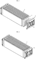
- FIGS. 1 and 2 A conventional battery module is shown in FIGS. 1 and 2 .
- the plurality of battery cells 1 may be stacked to form a cell stack 2, and a bus bar frame 4 including a bus bar 3 may be coupled to both sides of the battery cell stack 2 to form a serial connection, a parallel connection or a combination of serial and parallel connection among the plurality of battery cells 1.
- the conventional battery module separately requires a dedicated bus bar frame 4 suitable for a desired electrical connection type and the size and shape of the cell stack 2. Thus, whenever a new model is developed, it is needed to develop and manufacture a new bus bar frame suitable for the new model.
- the present disclosure is designed to solve the problems of the related art, and therefore the present disclosure is directed to easily manufacturing a battery module of various shapes just by changing the number of battery cells and the size or number of connectors according to a desired electric connection type without preparing a dedicated bus bar frame whenever developing a new battery module model.
- a battery module comprising: a unit module stack formed by stacking a plurality of unit modules, each of which includes a battery cell, a bus bar attached to an electrode lead provided to the battery cell and a bus bar frame attached to a terrace portion of the battery cell to accommodate at least a portion of the electrode lead and the bus bar; and a connector fixed by a connector holder provided to the bus bar frame to contact the bus bar.
- a fixed location of the connector may be made into a block by the connector holder.
- the bus bar frame may include: a first unit frame configured to cover at least a portion of an upper surface of the terrace portion; and a second unit frame configured to cover at least a portion of a lower surface of the terrace portion and coupled to the first unit frame.
- the first unit frame and the second unit frame may be shaped to be point-symmetric to each other.
- the first unit frame and the second unit frame may respectively have at least one fixing protrusion and a protrusion accommodation groove having a size and shape corresponding to the fixing protrusion, which are formed at facing surfaces thereof.
- the fixing protrusion formed at a coupling surface of the first unit frame may be formed to have a size and shape corresponding to the protrusion accommodation groove formed at a coupling surface of the second unit frame at a location corresponding thereto.
- the fixing protrusion and the protrusion accommodation groove may be further formed on surfaces of the first unit frame and the second unit frame opposite to the facing surfaces.
- a battery pack which is implemented by connecting a plurality of battery modules according to an embodiment of the present disclosure.
- a vehicle comprising the battery pack according to an embodiment of the present disclosure.
- a battery module of various shapes just by changing the number of battery cells and the size or number of connectors according to a desired electric connection type without preparing a dedicated bus bar frame whenever developing a new battery module model.
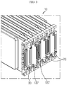
- FIG. 3 is a perspective view showing a portion of a battery module according to an embodiment of the present disclosure
- FIG. 4 is a front view showing a portion of the battery module according to an embodiment of the present disclosure
- FIG. 5 is a diagram showing a unit module stack applied to the battery module according to an embodiment of the present disclosure
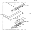
- FIG. 6 is an exploded perspective view showing a unit module applied to the battery module according to an embodiment of the present disclosure.
- a battery module according to an embodiment of the present disclosure includes a unit module stack 10, a connector 20, and an external terminal 30.
- the unit module stack 10 is a stack implemented by stacking a plurality of unit modules 100.
- Each unit module 100 includes a battery cell 110, a bus bar 120 connected to an electrode lead 114 of the battery cell 110, and a bus bar frame 130 attached to a terrace portion T of the battery cell 110.
- the unit module stacks 10 are stacked such that broad surfaces of neighboring battery cells 110 face each other, thereby forming one unit module stack 10.
- the connector 20 is a component adapted to electrically connect neighboring unit module stacks 10, and the connector 20 connects bus bars 120 provided in the neighboring unit module stacks 10 to each other.
- the external terminal 30 contacts the bus bar 120 provided to the unit module 100 disposed at the outermost side among the plurality of unit modules 100 of the unit module stack 10 and functions as a terminal for electrical connection with an external electronic device.
- FIG. 6 is an exploded perspective view showing a unit module applied to the battery module according to an embodiment of the present disclosure
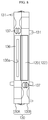
- FIG. 7 is a perspective view showing a battery cell applied to the battery module according to an embodiment of the present disclosure.
- a pouch-type battery cell may be used as the battery cell 110.
- the battery cell 110 may include an electrode assembly (not shown), a cell case 111, and an electrode lead 114.
- the electrode assembly is configured so that separators are interposed between positive electrode plates and negative electrode plates alternately stacked repeatedly, and separators are preferably disposed at both outermost sides thereof for insulation.
- the positive electrode plate includes a positive electrode current collector and a positive electrode active material layer coated on one or both surfaces of the positive electrode current collector.
- a positive electrode uncoated region where the positive electrode active material is not coated is formed at one end of the positive electrode plate.
- the positive electrode uncoated region functions as a positive electrode tab connected to the electrode lead 114.
- the negative electrode plate includes a negative electrode current collector and a negative electrode active material layer coated on one or both surfaces of the negative electrode current collector.
- a negative electrode uncoated region where the negative electrode active material is not coated is formed at one side of the negative electrode plate.
- the negative electrode uncoated region functions as a negative electrode tab connected to the electrode lead 114.
- the separator is interposed between the positive electrode plate and the negative electrode plate to prevent the electrode plates having different polarities from contacting each other directly.
- the separator may be made of a porous material to allow ions to move between the positive electrode plate and the negative electrode plate by using an electrolyte as a medium.
- the cell case 111 includes an accommodation portion 112 for accommodating the electrode assembly (not shown) and a sealing portion 113 extending in a circumferential direction of the accommodation portion so that the electrode lead 114 is thermally fused thereto in an outwardly drawn state to seal the cell case 111.
- the electrode lead 114 is classified into a positive electrode lead connected to the positive electrode tab and a negative electrode lead connected to the negative electrode tab, and the positive electrode lead and the negative electrode lead are drawn out of the cell case 111 in opposite directions.
- a region positioned in the direction to which the electrode lead 114 is drawn out is particularly defined as a terrace portion T.
- bus bar 120 of the unit module 100 will be described in detail with reference to FIG. 6 again.
- the bus bar 120 is bonded to the electrode lead 114 by welding in a state of being fixed to the bus bar frame 130, so that a portion of the bus bar 120 is located inside the bus bar frame 130 and the remaining portion is exposed out of the bus bar frame 130.
- the portion of the bus bar 120 exposed out of the bus bar frame 130 is connected to the connector 20 (see FIGS. 3 and 4 ) explained above, thereby electrically connecting neighboring battery unit modules 100.
- the bus bar 120 includes a bonding portion 121, an exposed portion 122, and a hook portion 123.
- the bonding portion 121 extends in a direction parallel to the electrode lead 114, namely in the horizontal direction, to contact the electrode lead 114 and is located inside the bus bar frame 130.
- the exposed portion 122 is bent from the bonding portion 121 and extends in a direction perpendicular to the bonding portion 121, and also the exposed portion 122 is drawn out of the bus bar frame 130 and placed on a bus bar placing portion 136, explained later.
- the hook portion 123 extends from an end of the bonding portion 121 in a direction parallel to the exposed portion 122, and one or more hook portions 123 are provided.
- the hook portion 123 allows the bus bar 120 to be fixed to the inside of the bus bar frame 130 and is coupled or fixed to a hook fixing portion 135 provided at an inner surface of the bus bar frame 130.
- the bus bar 120 is fixed and mounted inside the bus bar frame 130 so that a portion of the bus bar 120 is exposed out of the bus bar frame 130. Also, the bonding portion 121 located inside the bus bar frame 130 is bonded to the lower surface of the electrode lead 114, and the exposed portion 122 located at the outer side of the bus bar frame 130 is connected to the connector 20 to electrically connect neighboring unit modules 100 to each other.
- bus bar frame 130 of the unit module 100 will be described in detail with reference to FIGS. 8 to 11 along with FIG. 6 .
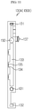
- FIG. 8 is a front view showing that the unit module applied to the battery module according to an embodiment of the present disclosure is coupled to a bus bar
- FIGS. 9 and 10 are perspective views showing a unit frame of a bus bar frame applied to the battery module according to an embodiment of the present disclosure at different angles
- FIG. 11 is a side view showing the unit frame of the bus bar frame applied to the battery module according to an embodiment of the present disclosure.
- the bus bar frame 130 is attached to the terrace portion T of the battery cell 110 and functions as a support for the bus bar 120 as described above.
- the bus bar frame 130 is implemented by combining a first unit frame 130A and a second unit frame 130B having the same shape. That is, the first unit frame 130A and the second unit frame 130B are components having the same shape, where the first unit frame 130A covers at least a portion of the upper surface of the terrace portion T and the second unit frame 130B covers at least a portion of the lower portion of the terrace portion T.
- the first unit frame 130A and the second unit frame 130B are coupled to each other.
- first unit frame 130A and the second unit frame 130B are coupled to each other to form one bus bar frame 130, the first unit frame 130A and the second unit frame 130B are point-symmetric to each other.
- the first unit frame 130A has the same shape as the second unit frame 130B.
- the bus bar 120 is drawn through a gap of the coupling surfaces thereof. That is, the exposed portion 122 of the bus bar 120 is drawn through the gap between the coupling surfaces of the first unit frame 130A and the second unit frame 130B.
- the drawn bus bar 120 is bent toward the first unit frame 130A or the second unit frame 130B and is placed on the bus bar placing portion 136 formed at the first unit frame 130A or the second unit frame 130B.
- the bending direction of the bus bar 120 is determined according to whether the bus bar 120 is electrically connected to the unit module 100 in contact with the first unit frame 130A or the unit module in contact with the second unit frame 130B.
- bus bar frame 130 As described above, since the pair of unit frames 130A, 130B are components having the same shape, the detailed structure of the bus bar frame 130 will be described based on one unit frame (130A or 130B) with reference to FIGS. 9 to 11 .
- the unit frames 130A, 130B may include a fixing protrusion 131, a protrusion accommodation groove 132, a welding slit 133, a hook accommodation groove 134, a hook fixing portion 135, a bus bar placing portion 136, and a connector holder 137.
- At least one fixing protrusion 131 and at least one protrusion accommodation groove 132 are formed at the coupling surfaces of the unit frames 130A, 130B and surfaces opposite thereto, and the fixing protrusion 131 and the protrusion accommodation groove 132 are formed in pairs at corresponding locations at the facing surfaces of the unit frames 130A, 130B.
- the fixing protrusion 131 formed at the coupling surface of the first unit frame 130A has a size and shape corresponding to the protrusion accommodation groove 132 formed at the coupling surface of the second unit frame 130B at a position corresponding thereto
- the protrusion accommodation groove 132 formed at the coupling portion of the first unit frame 130A has a size and shape corresponding to the fixing protrusion 131 formed at the coupling surface of the second unit frame 130B at a location corresponding thereto.
- the first unit frame 130A and the second unit frame 130B may be coupled and fixed to each other.
- fixing protrusion 131 and the protrusion accommodation groove 132 are formed not only at the facing surfaces of the unit frames 130A, 130B but also at surfaces opposite thereto, neighboring unit modules 100A, 100B (see FIGS. 4 ad 5) may also be coupled using the fixing protrusion 131 and the protrusion accommodation groove 132.
- the welding slit 133 is formed at a surface perpendicular to the bonding surface of the unit frames 130A, 130B and allows welding to be performed on the bonding portion of the electrode lead 114 (see FIG. 5 ) and the bus bar 120 located inside the bus bar frame 130.
- the welding slit 133 may be formed to have a length corresponding to the width of the bonding portion of the electrode lead 114 and the bus bar 120 so that welding is performed over the entire width on the bonding portion of the electrode lead 114 and the bus bar 120.
- the bus bar frame 130 is a component attached to the battery cell 110 to configure the unit module 100.
- the bus bar frame 130 may also function as a pressing jig for pressing the bus bar 120 fixed and coupled therein to be closely adhered to the electrode lead 114. Also, since the welding slit 133 is provided, welding may be performed easily without any additional work for securing a space for welding.
- the hook accommodation groove 134 extends from the welding slit 133 and gives a space in which the hook portion 123 of the bus bar 120 may be accommodated. In view of this function, the hook accommodation groove 134 may be formed in the same number as the hook portion 123.
- the hook fixing portion 135 is formed on an inner wall of the hook accommodation groove 134 and has a shape corresponding to the hook portion 123 so as to be fastened with the hook portion 123. That is, the hook fixing portion 135 may be formed in various shapes such as a groove or a protrusion formed on the hook accommodation groove 134.
- the bus bar placing portion 136 is formed concavely on the side surface of the bus bar frame 130 to have a size and shape corresponding to the exposed portion 122 so that the exposed portion 122 of the bus bar 120 exposed out of the bus bar frame 130 may be placed thereon without shaking.
- the bus bar placing portion 136 may have a damage-preventing groove 136a formed at the surface thereof as a concave groove along in the length direction thereof.
- the damage-preventing groove 136a prevents the bus bar placing portion 136 from being damaged during the welding process for coupling the bus bar 120 and the connector 20 (see FIGS. 3 and 4 ).
- the bus bar frame 130 may be made of an injection-molded resin.
- the bus bar placing portion 136 is highly likely to be damaged by heat.
- the groove is formed at a position corresponding to the welding line where the welding is performed, so that the bus bar 120 and the bus bar placing portion 136 do not contact each other partially, thereby preventing the injection-molded resin from melting due to heat conduction caused by welding.
- the connector holder 137 is formed to protrude on the same plane as the bus bar placing portion 136 of the unit frames 130A, 130B, and at least one connector holder 137 is formed at one longitudinal side and/or the other longitudinal side of the unit frames 130A, 130B.
- the connector holder 137 is a component applied to fix the connector 20 when welding is performed to bond the connector 20 and the bus bar 120. That is, the fixed location of the connector 20 is made into a block by the connector holder 137, and the connector holder 137 is inserted through an insert hole formed in the connector 20 with a size and shape corresponding to the connector holder 137 to fix the connector 20. Thus, it is possible to perform welding for bonding the connector 20 and the bus bar 120 without applying a separate fixing jig.
- the connector holders 137 respectively provided to a pair of neighboring unit modules 100A, 100B or three or more neighboring unit modules 100 are simultaneously fastened together with one connector 20.
- the bus bar 120 of the first unit module 100A and the bus bar 120 of the second unit module 100B which are bent toward each other, are in common contact with one connector 20 to electrically connect the pair of unit modules 100A, 100B or three or more unit modules 100.
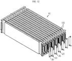
- FIGS. 12 and 13 are diagrams showing that thirteen battery cells are connected to a connector coupling site made into a block by using several bus bar of the same kind in 1P/13S type
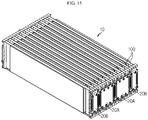
- FIGS. 14 and 15 are diagrams showing that twelve battery cells are connected to the connector coupling site made into a block by using two kinds of bus bars in 2P/6S type.
- the unit modules 100 of the unit module stack 10 are connected in series with each other. If all the unit modules 100 are connected to each other in series as above, the plurality of connectors 20 used to connect the pair of neighboring unit modules 100 may have the same size and/or shape.
- some unit modules 100 are connected in parallel to form a parallel connection group, and neighboring parallel connection groups are connected in series. If electrical connection is made to combine serial connection and parallel connection as above, a first connector 20A used for the parallel connection and a second connector 20B used for the serial connection may have different sizes and/or shapes.
- unit module 100 of the unit module stack 10 since unit module 100 of the unit module stack 10 has a connector holder for fixing the connector 20, the side where the connector 20 is fixed is made into a block. Accordingly, a desired electrical connection may be implemented just by applying the size and shape of the connector 20 differently, and a desired capacitance and voltage may be obtained by changing the number of connected unit modules 100.
Landscapes
- Chemical & Material Sciences (AREA)
- Chemical Kinetics & Catalysis (AREA)
- Electrochemistry (AREA)
- General Chemical & Material Sciences (AREA)
- Connection Of Batteries Or Terminals (AREA)
- Battery Mounting, Suspending (AREA)
Applications Claiming Priority (2)
| Application Number | Priority Date | Filing Date | Title |
|---|---|---|---|
| KR1020180046305A KR102328730B1 (ko) | 2018-04-20 | 2018-04-20 | 직/병렬 연결을 용이하게 하는 구조를 갖는 배터리 모듈 및 이를 포함하는 배터리 팩 |
| PCT/KR2019/002152 WO2019203433A1 (fr) | 2018-04-20 | 2019-02-21 | Module de batterie comportant une structure facilitant les connexions série-parallèle et bloc-batterie comprenant celui-ci |
Publications (2)
| Publication Number | Publication Date |
|---|---|
| EP3694015A1 true EP3694015A1 (fr) | 2020-08-12 |
| EP3694015A4 EP3694015A4 (fr) | 2021-05-05 |
Family
ID=68239638
Family Applications (1)
| Application Number | Title | Priority Date | Filing Date |
|---|---|---|---|
| EP19788636.9A Pending EP3694015A4 (fr) | 2018-04-20 | 2019-02-21 | Module de batterie comportant une structure facilitant les connexions série-parallèle et bloc-batterie comprenant celui-ci |
Country Status (6)
| Country | Link |
|---|---|
| US (1) | US11431063B2 (fr) |
| EP (1) | EP3694015A4 (fr) |
| JP (1) | JP7230011B2 (fr) |
| KR (1) | KR102328730B1 (fr) |
| CN (1) | CN111226326B (fr) |
| WO (1) | WO2019203433A1 (fr) |
Cited By (2)
| Publication number | Priority date | Publication date | Assignee | Title |
|---|---|---|---|---|
| WO2024134051A1 (fr) | 2022-12-21 | 2024-06-27 | Safran Electrical & Power | Système de batterie de courant continu haute tension a module de stockage basse tension |
| EP4131584A4 (fr) * | 2020-08-20 | 2024-08-14 | Lg Energy Solution Ltd | Module de batterie comprenant un élément d'isolation thermique |
Families Citing this family (10)
| Publication number | Priority date | Publication date | Assignee | Title |
|---|---|---|---|---|
| CN210744017U (zh) * | 2019-10-21 | 2020-06-12 | 宁德时代新能源科技股份有限公司 | 线束隔离板组件、电池模块、电池组及装置 |
| KR20210089448A (ko) * | 2020-01-08 | 2021-07-16 | 주식회사 엘지에너지솔루션 | 접속 플레이트를 구비한 배터리 팩 |
| KR20210125723A (ko) * | 2020-04-09 | 2021-10-19 | 주식회사 엘지에너지솔루션 | 전지 모듈 및 그 제조 방법 |
| KR20210129828A (ko) * | 2020-04-21 | 2021-10-29 | 현대자동차주식회사 | 배터리 모듈 |
| KR20210133566A (ko) * | 2020-04-29 | 2021-11-08 | 주식회사 엘지에너지솔루션 | 전지 모듈 및 이를 포함하는 전지팩 |
| JP7523845B2 (ja) * | 2020-07-02 | 2024-07-29 | エルジー エナジー ソリューション リミテッド | スウェリングの際に噴出するフレア及びスパークを捕集することができるポケットを備えた電池モジュール |
| KR20220094518A (ko) * | 2020-12-29 | 2022-07-06 | 에스케이온 주식회사 | 배터리모듈 |
| WO2022251158A1 (fr) * | 2021-05-24 | 2022-12-01 | Spear Power Systems, Inc. | Commutateur et système de batterie |
| KR20230134375A (ko) * | 2022-03-14 | 2023-09-21 | 에스케이온 주식회사 | 배터리 셀 어셈블리 및 이를 포함하는 배터리 모듈 |
| KR20240094743A (ko) * | 2022-12-16 | 2024-06-25 | 주식회사 엘지에너지솔루션 | 전지 모듈 및 이를 포함하는 전지 팩 |
Family Cites Families (26)
| Publication number | Priority date | Publication date | Assignee | Title |
|---|---|---|---|---|
| JP3802457B2 (ja) | 2002-06-28 | 2006-07-26 | 三洋電機株式会社 | 電源装置 |
| JP4570888B2 (ja) | 2004-03-18 | 2010-10-27 | 富士重工業株式会社 | 蓄電体装置 |
| JP2005285452A (ja) | 2004-03-29 | 2005-10-13 | Sanyo Electric Co Ltd | 電源装置および電源装置を構成する電源モジュール |
| KR100932227B1 (ko) * | 2005-09-02 | 2009-12-16 | 주식회사 엘지화학 | 이차전지 및 이를 포함하는 전지모듈 |
| WO2007121445A2 (fr) * | 2006-04-18 | 2007-10-25 | Securaplane Technologies, Inc. | Schéma d'interconnexion d'une batterie par bus |
| JP4379467B2 (ja) * | 2006-12-11 | 2009-12-09 | 日産自動車株式会社 | 電池モジュール |
| WO2011108857A2 (fr) * | 2010-03-05 | 2011-09-09 | (주)브이이엔에스 | Cartouche de pile |
| US8980465B2 (en) * | 2011-01-05 | 2015-03-17 | Samsung Sdi Co., Ltd. | Battery pack |
| JP3169685U (ja) | 2011-05-31 | 2011-08-11 | 古河電池株式会社 | 電池モジュール |
| KR20130019697A (ko) * | 2011-08-17 | 2013-02-27 | 삼성에스디아이 주식회사 | 전지 팩 및 이를 포함한 전지 모듈 |
| US9005794B2 (en) | 2011-10-21 | 2015-04-14 | Tyco Electronics Corporation | Battery connector system |
| KR101367693B1 (ko) | 2011-11-16 | 2014-02-28 | (주)케이엔알시스템 | 씰 구조물 및 이를 포함하는 로터리 액추에이터 |
| KR101392799B1 (ko) | 2012-06-07 | 2014-05-14 | 주식회사 엘지화학 | 안정성이 향상된 구조 및 높은 냉각 효율성을 갖는 전지모듈 |
| JP6079785B2 (ja) | 2012-11-09 | 2017-02-22 | 日産自動車株式会社 | 組電池および組電池の製造方法 |
| KR102117848B1 (ko) | 2013-11-13 | 2020-06-02 | 에스케이이노베이션 주식회사 | 배터리 모듈 및 이를 제작하는 방법 |
| KR101735875B1 (ko) | 2013-11-20 | 2017-05-15 | 삼성에스디아이 주식회사 | 이차 전지 모듈 |
| KR101773105B1 (ko) | 2014-07-31 | 2017-08-30 | 주식회사 엘지화학 | 배터리 모듈 |
| US9786894B2 (en) * | 2014-11-03 | 2017-10-10 | Lg Chem, Ltd. | Battery pack |
| KR102283960B1 (ko) * | 2015-03-17 | 2021-07-30 | 삼성에스디아이 주식회사 | 베터리 팩 |
| KR102032503B1 (ko) | 2015-11-05 | 2019-10-15 | 주식회사 엘지화학 | 배터리 모듈, 이러한 배터리 모듈을 포함하는 배터리 팩 및 이러한 배터리 팩을 포함하는 자동차 |
| KR102034208B1 (ko) * | 2016-03-03 | 2019-10-18 | 주식회사 엘지화학 | 배터리 모듈, 이러한 배터리 모듈을 포함하는 배터리 팩 및 이러한 배터리 팩을 포함하는 자동차 |
| JP2018006017A (ja) | 2016-06-28 | 2018-01-11 | 三浦工業株式会社 | 燃料電池システム |
| KR102102927B1 (ko) | 2016-10-06 | 2020-04-21 | 주식회사 엘지화학 | 배터리 모듈, 이러한 배터리 모듈을 포함하는 배터리 팩 및 이러한 배터리 팩을 포함하는 자동차 |
| KR20180046305A (ko) | 2016-10-27 | 2018-05-08 | (주)동인기연 | 유모차 |
| KR102483682B1 (ko) * | 2017-10-30 | 2023-01-02 | 삼성에스디아이 주식회사 | 배터리 팩 |
| KR102514123B1 (ko) | 2018-04-19 | 2023-03-23 | 주식회사 엘지에너지솔루션 | 용접을 용이하게 할 수 있는 버스바 프레임 구조를 구비하는 단위 모듈 및 이를 포함하는 배터리 모듈 |
-
2018
- 2018-04-20 KR KR1020180046305A patent/KR102328730B1/ko active IP Right Grant
-
2019
- 2019-02-21 CN CN201980005187.5A patent/CN111226326B/zh active Active
- 2019-02-21 WO PCT/KR2019/002152 patent/WO2019203433A1/fr unknown
- 2019-02-21 JP JP2020517098A patent/JP7230011B2/ja active Active
- 2019-02-21 US US16/753,145 patent/US11431063B2/en active Active
- 2019-02-21 EP EP19788636.9A patent/EP3694015A4/fr active Pending
Cited By (3)
| Publication number | Priority date | Publication date | Assignee | Title |
|---|---|---|---|---|
| EP4131584A4 (fr) * | 2020-08-20 | 2024-08-14 | Lg Energy Solution Ltd | Module de batterie comprenant un élément d'isolation thermique |
| WO2024134051A1 (fr) | 2022-12-21 | 2024-06-27 | Safran Electrical & Power | Système de batterie de courant continu haute tension a module de stockage basse tension |
| FR3144434A1 (fr) | 2022-12-21 | 2024-06-28 | Safran Electrical & Power | Système de batterie de courant continu haute tension a module de stockage basse tension |
Also Published As
| Publication number | Publication date |
|---|---|
| JP2020535601A (ja) | 2020-12-03 |
| CN111226326A (zh) | 2020-06-02 |
| KR102328730B1 (ko) | 2021-11-17 |
| JP7230011B2 (ja) | 2023-02-28 |
| US11431063B2 (en) | 2022-08-30 |
| KR20190122477A (ko) | 2019-10-30 |
| US20200295337A1 (en) | 2020-09-17 |
| WO2019203433A1 (fr) | 2019-10-24 |
| CN111226326B (zh) | 2022-10-18 |
| EP3694015A4 (fr) | 2021-05-05 |
Similar Documents
| Publication | Publication Date | Title |
|---|---|---|
| US11431063B2 (en) | Battery module having structure facilitating series-parallel connections and battery pack comprising same | |
| US11302999B2 (en) | Unit module including busbar frame structure which can facilitate welding, and battery module including same | |
| KR102395683B1 (ko) | Fpcb에 실장된 커넥터를 구비하는 배터리 모듈, 이를 포함하는 배터리 팩 및 자동차 | |
| CN110692149B (zh) | 电池模块、包括该电池模块的电池组和车辆 | |
| US10096867B2 (en) | Compact secondary battery module integrated with BMS | |
| JP7128287B2 (ja) | エネルギー密度が向上した構造を有するバッテリーモジュール、それを含むバッテリーパック及び自動車 | |
| JP7522241B2 (ja) | バッテリータブの構造 | |
| CN106486634B (zh) | 电池模块 | |
| JP7041799B2 (ja) | バッテリーモジュール及びこれを含むバッテリーパック | |
| US20160164051A1 (en) | Secondary battery and battery pack including the same | |
| KR20120007508A (ko) | 갈바니 전지용 전극 스택 | |
| KR102488138B1 (ko) | 각주형 전기화학 셀 | |
| CN114651370B (zh) | 具有汇流条的电池模块、电池组和车辆 | |
| CN111801810A (zh) | 包括内盖的电池模块 | |
| CN107251263B (zh) | 电池单池和电池系统 | |
| US20190109348A1 (en) | Energy storage device and method of manufacturing energy storage device | |
| JP6454424B2 (ja) | バッテリセル、及び、バッテリシステム | |
| US20210313664A1 (en) | Battery Module Having Insulation Pad With Extended Length, and Battery Pack and Vehicle Comprising Same | |
| US20230261278A1 (en) | Battery pack and vehicle comprising same | |
| KR20230171556A (ko) | 단자 구조가 개선된 이차전지 | |
| JP2004111183A (ja) | 集合型電池及びその製造方法 |
Legal Events
| Date | Code | Title | Description |
|---|---|---|---|
| STAA | Information on the status of an ep patent application or granted ep patent |
Free format text: STATUS: THE INTERNATIONAL PUBLICATION HAS BEEN MADE |
|
| PUAI | Public reference made under article 153(3) epc to a published international application that has entered the european phase |
Free format text: ORIGINAL CODE: 0009012 |
|
| STAA | Information on the status of an ep patent application or granted ep patent |
Free format text: STATUS: REQUEST FOR EXAMINATION WAS MADE |
|
| 17P | Request for examination filed |
Effective date: 20200504 |
|
| AK | Designated contracting states |
Kind code of ref document: A1 Designated state(s): AL AT BE BG CH CY CZ DE DK EE ES FI FR GB GR HR HU IE IS IT LI LT LU LV MC MK MT NL NO PL PT RO RS SE SI SK SM TR |
|
| AX | Request for extension of the european patent |
Extension state: BA ME |
|
| REG | Reference to a national code |
Ref country code: DE Ref legal event code: R079 Free format text: PREVIOUS MAIN CLASS: H01M0002100000 Ipc: H01M0050507000 |
|
| A4 | Supplementary search report drawn up and despatched |
Effective date: 20210406 |
|
| RIC1 | Information provided on ipc code assigned before grant |
Ipc: H01M 50/507 20210101AFI20210329BHEP Ipc: H01M 50/502 20210101ALI20210329BHEP Ipc: H01M 50/211 20210101ALI20210329BHEP Ipc: H01M 50/50 20210101ALI20210329BHEP Ipc: H01M 50/20 20210101ALI20210329BHEP |
|
| DAV | Request for validation of the european patent (deleted) | ||
| DAX | Request for extension of the european patent (deleted) | ||
| RAP1 | Party data changed (applicant data changed or rights of an application transferred) |
Owner name: LG ENERGY SOLUTION LTD. |
|
| RAP3 | Party data changed (applicant data changed or rights of an application transferred) |
Owner name: LG ENERGY SOLUTION, LTD. |
|
| STAA | Information on the status of an ep patent application or granted ep patent |
Free format text: STATUS: EXAMINATION IS IN PROGRESS |
|
| 17Q | First examination report despatched |
Effective date: 20231031 |