EP3693220B1 - Verfahren zum betrieb eines selbstfahrenden kraftfahrzeugs - Google Patents
Verfahren zum betrieb eines selbstfahrenden kraftfahrzeugs Download PDFInfo
- Publication number
- EP3693220B1 EP3693220B1 EP19213026.8A EP19213026A EP3693220B1 EP 3693220 B1 EP3693220 B1 EP 3693220B1 EP 19213026 A EP19213026 A EP 19213026A EP 3693220 B1 EP3693220 B1 EP 3693220B1
- Authority
- EP
- European Patent Office
- Prior art keywords
- data set
- control data
- lad
- motor vehicle
- lamp
- Prior art date
- Legal status (The legal status is an assumption and is not a legal conclusion. Google has not performed a legal analysis and makes no representation as to the accuracy of the status listed.)
- Active
Links
- 238000000034 method Methods 0.000 title claims description 13
- 238000004590 computer program Methods 0.000 claims description 2
- 238000011156 evaluation Methods 0.000 claims 4
- 230000000694 effects Effects 0.000 claims 2
- 230000011664 signaling Effects 0.000 description 3
- 230000003213 activating effect Effects 0.000 description 2
- 238000001514 detection method Methods 0.000 description 2
- 230000005923 long-lasting effect Effects 0.000 description 2
- 239000000463 material Substances 0.000 description 2
- 239000004065 semiconductor Substances 0.000 description 2
- 239000010981 turquoise Substances 0.000 description 2
- 230000004913 activation Effects 0.000 description 1
- 238000005286 illumination Methods 0.000 description 1
- 239000011159 matrix material Substances 0.000 description 1
Images


Classifications
-
- B—PERFORMING OPERATIONS; TRANSPORTING
- B60—VEHICLES IN GENERAL
- B60Q—ARRANGEMENT OF SIGNALLING OR LIGHTING DEVICES, THE MOUNTING OR SUPPORTING THEREOF OR CIRCUITS THEREFOR, FOR VEHICLES IN GENERAL
- B60Q1/00—Arrangement of optical signalling or lighting devices, the mounting or supporting thereof or circuits therefor
- B60Q1/26—Arrangement of optical signalling or lighting devices, the mounting or supporting thereof or circuits therefor the devices being primarily intended to indicate the vehicle, or parts thereof, or to give signals, to other traffic
- B60Q1/50—Arrangement of optical signalling or lighting devices, the mounting or supporting thereof or circuits therefor the devices being primarily intended to indicate the vehicle, or parts thereof, or to give signals, to other traffic for indicating other intentions or conditions, e.g. request for waiting or overtaking
- B60Q1/525—Arrangement of optical signalling or lighting devices, the mounting or supporting thereof or circuits therefor the devices being primarily intended to indicate the vehicle, or parts thereof, or to give signals, to other traffic for indicating other intentions or conditions, e.g. request for waiting or overtaking automatically indicating risk of collision between vehicles in traffic or with pedestrians, e.g. after risk assessment using the vehicle sensor data
-
- B—PERFORMING OPERATIONS; TRANSPORTING
- B60—VEHICLES IN GENERAL
- B60Q—ARRANGEMENT OF SIGNALLING OR LIGHTING DEVICES, THE MOUNTING OR SUPPORTING THEREOF OR CIRCUITS THEREFOR, FOR VEHICLES IN GENERAL
- B60Q1/00—Arrangement of optical signalling or lighting devices, the mounting or supporting thereof or circuits therefor
- B60Q1/26—Arrangement of optical signalling or lighting devices, the mounting or supporting thereof or circuits therefor the devices being primarily intended to indicate the vehicle, or parts thereof, or to give signals, to other traffic
- B60Q1/28—Arrangement of optical signalling or lighting devices, the mounting or supporting thereof or circuits therefor the devices being primarily intended to indicate the vehicle, or parts thereof, or to give signals, to other traffic for indicating front of vehicle
-
- B—PERFORMING OPERATIONS; TRANSPORTING
- B60—VEHICLES IN GENERAL
- B60Q—ARRANGEMENT OF SIGNALLING OR LIGHTING DEVICES, THE MOUNTING OR SUPPORTING THEREOF OR CIRCUITS THEREFOR, FOR VEHICLES IN GENERAL
- B60Q1/00—Arrangement of optical signalling or lighting devices, the mounting or supporting thereof or circuits therefor
- B60Q1/26—Arrangement of optical signalling or lighting devices, the mounting or supporting thereof or circuits therefor the devices being primarily intended to indicate the vehicle, or parts thereof, or to give signals, to other traffic
- B60Q1/34—Arrangement of optical signalling or lighting devices, the mounting or supporting thereof or circuits therefor the devices being primarily intended to indicate the vehicle, or parts thereof, or to give signals, to other traffic for indicating change of drive direction
- B60Q1/346—Arrangement of optical signalling or lighting devices, the mounting or supporting thereof or circuits therefor the devices being primarily intended to indicate the vehicle, or parts thereof, or to give signals, to other traffic for indicating change of drive direction with automatic actuation
-
- B—PERFORMING OPERATIONS; TRANSPORTING
- B60—VEHICLES IN GENERAL
- B60Q—ARRANGEMENT OF SIGNALLING OR LIGHTING DEVICES, THE MOUNTING OR SUPPORTING THEREOF OR CIRCUITS THEREFOR, FOR VEHICLES IN GENERAL
- B60Q1/00—Arrangement of optical signalling or lighting devices, the mounting or supporting thereof or circuits therefor
- B60Q1/26—Arrangement of optical signalling or lighting devices, the mounting or supporting thereof or circuits therefor the devices being primarily intended to indicate the vehicle, or parts thereof, or to give signals, to other traffic
- B60Q1/34—Arrangement of optical signalling or lighting devices, the mounting or supporting thereof or circuits therefor the devices being primarily intended to indicate the vehicle, or parts thereof, or to give signals, to other traffic for indicating change of drive direction
- B60Q1/38—Arrangement of optical signalling or lighting devices, the mounting or supporting thereof or circuits therefor the devices being primarily intended to indicate the vehicle, or parts thereof, or to give signals, to other traffic for indicating change of drive direction using immovably-mounted light sources, e.g. fixed flashing lamps
- B60Q1/381—Arrangement of optical signalling or lighting devices, the mounting or supporting thereof or circuits therefor the devices being primarily intended to indicate the vehicle, or parts thereof, or to give signals, to other traffic for indicating change of drive direction using immovably-mounted light sources, e.g. fixed flashing lamps with several light sources activated in sequence, e.g. to create a sweep effect
-
- B—PERFORMING OPERATIONS; TRANSPORTING
- B60—VEHICLES IN GENERAL
- B60Q—ARRANGEMENT OF SIGNALLING OR LIGHTING DEVICES, THE MOUNTING OR SUPPORTING THEREOF OR CIRCUITS THEREFOR, FOR VEHICLES IN GENERAL
- B60Q1/00—Arrangement of optical signalling or lighting devices, the mounting or supporting thereof or circuits therefor
- B60Q1/26—Arrangement of optical signalling or lighting devices, the mounting or supporting thereof or circuits therefor the devices being primarily intended to indicate the vehicle, or parts thereof, or to give signals, to other traffic
- B60Q1/50—Arrangement of optical signalling or lighting devices, the mounting or supporting thereof or circuits therefor the devices being primarily intended to indicate the vehicle, or parts thereof, or to give signals, to other traffic for indicating other intentions or conditions, e.g. request for waiting or overtaking
- B60Q1/503—Arrangement of optical signalling or lighting devices, the mounting or supporting thereof or circuits therefor the devices being primarily intended to indicate the vehicle, or parts thereof, or to give signals, to other traffic for indicating other intentions or conditions, e.g. request for waiting or overtaking using luminous text or symbol displays in or on the vehicle, e.g. static text
- B60Q1/5035—Arrangement of optical signalling or lighting devices, the mounting or supporting thereof or circuits therefor the devices being primarily intended to indicate the vehicle, or parts thereof, or to give signals, to other traffic for indicating other intentions or conditions, e.g. request for waiting or overtaking using luminous text or symbol displays in or on the vehicle, e.g. static text electronic displays
- B60Q1/5037—Arrangement of optical signalling or lighting devices, the mounting or supporting thereof or circuits therefor the devices being primarily intended to indicate the vehicle, or parts thereof, or to give signals, to other traffic for indicating other intentions or conditions, e.g. request for waiting or overtaking using luminous text or symbol displays in or on the vehicle, e.g. static text electronic displays the display content changing automatically, e.g. depending on traffic situation
-
- B—PERFORMING OPERATIONS; TRANSPORTING
- B60—VEHICLES IN GENERAL
- B60Q—ARRANGEMENT OF SIGNALLING OR LIGHTING DEVICES, THE MOUNTING OR SUPPORTING THEREOF OR CIRCUITS THEREFOR, FOR VEHICLES IN GENERAL
- B60Q1/00—Arrangement of optical signalling or lighting devices, the mounting or supporting thereof or circuits therefor
- B60Q1/26—Arrangement of optical signalling or lighting devices, the mounting or supporting thereof or circuits therefor the devices being primarily intended to indicate the vehicle, or parts thereof, or to give signals, to other traffic
- B60Q1/50—Arrangement of optical signalling or lighting devices, the mounting or supporting thereof or circuits therefor the devices being primarily intended to indicate the vehicle, or parts thereof, or to give signals, to other traffic for indicating other intentions or conditions, e.g. request for waiting or overtaking
- B60Q1/543—Arrangement of optical signalling or lighting devices, the mounting or supporting thereof or circuits therefor the devices being primarily intended to indicate the vehicle, or parts thereof, or to give signals, to other traffic for indicating other intentions or conditions, e.g. request for waiting or overtaking for indicating other states or conditions of the vehicle
-
- G—PHYSICS
- G05—CONTROLLING; REGULATING
- G05D—SYSTEMS FOR CONTROLLING OR REGULATING NON-ELECTRIC VARIABLES
- G05D1/00—Control of position, course, altitude or attitude of land, water, air or space vehicles, e.g. using automatic pilots
- G05D1/0088—Control of position, course, altitude or attitude of land, water, air or space vehicles, e.g. using automatic pilots characterized by the autonomous decision making process, e.g. artificial intelligence, predefined behaviours
-
- G—PHYSICS
- G05—CONTROLLING; REGULATING
- G05D—SYSTEMS FOR CONTROLLING OR REGULATING NON-ELECTRIC VARIABLES
- G05D1/00—Control of position, course, altitude or attitude of land, water, air or space vehicles, e.g. using automatic pilots
- G05D1/02—Control of position or course in two dimensions
- G05D1/021—Control of position or course in two dimensions specially adapted to land vehicles
- G05D1/0212—Control of position or course in two dimensions specially adapted to land vehicles with means for defining a desired trajectory
-
- H—ELECTRICITY
- H05—ELECTRIC TECHNIQUES NOT OTHERWISE PROVIDED FOR
- H05B—ELECTRIC HEATING; ELECTRIC LIGHT SOURCES NOT OTHERWISE PROVIDED FOR; CIRCUIT ARRANGEMENTS FOR ELECTRIC LIGHT SOURCES, IN GENERAL
- H05B45/00—Circuit arrangements for operating light-emitting diodes [LED]
- H05B45/10—Controlling the intensity of the light
-
- H—ELECTRICITY
- H05—ELECTRIC TECHNIQUES NOT OTHERWISE PROVIDED FOR
- H05B—ELECTRIC HEATING; ELECTRIC LIGHT SOURCES NOT OTHERWISE PROVIDED FOR; CIRCUIT ARRANGEMENTS FOR ELECTRIC LIGHT SOURCES, IN GENERAL
- H05B45/00—Circuit arrangements for operating light-emitting diodes [LED]
- H05B45/20—Controlling the colour of the light
-
- B—PERFORMING OPERATIONS; TRANSPORTING
- B60—VEHICLES IN GENERAL
- B60Q—ARRANGEMENT OF SIGNALLING OR LIGHTING DEVICES, THE MOUNTING OR SUPPORTING THEREOF OR CIRCUITS THEREFOR, FOR VEHICLES IN GENERAL
- B60Q2300/00—Indexing codes for automatically adjustable headlamps or automatically dimmable headlamps
- B60Q2300/40—Indexing codes relating to other road users or special conditions
- B60Q2300/45—Special conditions, e.g. pedestrians, road signs or potential dangers
-
- B—PERFORMING OPERATIONS; TRANSPORTING
- B60—VEHICLES IN GENERAL
- B60Q—ARRANGEMENT OF SIGNALLING OR LIGHTING DEVICES, THE MOUNTING OR SUPPORTING THEREOF OR CIRCUITS THEREFOR, FOR VEHICLES IN GENERAL
- B60Q2400/00—Special features or arrangements of exterior signal lamps for vehicles
- B60Q2400/20—Multi-color single source or LED matrix, e.g. yellow blinker and red brake lamp generated by single lamp
-
- B—PERFORMING OPERATIONS; TRANSPORTING
- B60—VEHICLES IN GENERAL
- B60Q—ARRANGEMENT OF SIGNALLING OR LIGHTING DEVICES, THE MOUNTING OR SUPPORTING THEREOF OR CIRCUITS THEREFOR, FOR VEHICLES IN GENERAL
- B60Q2400/00—Special features or arrangements of exterior signal lamps for vehicles
- B60Q2400/30—Daytime running lights [DRL], e.g. circuits or arrangements therefor
Definitions
- the invention relates to a method for operating a self-driving motor vehicle.
- Self-driving motor vehicles are motor vehicles that can drive, control and park without the influence of a human driver (highly automated driving or autonomous driving). In the event that no manual control is required on the part of a driver, the term robot car is also used. The driver's seat can remain unoccupied; possibly no steering wheel, brake and accelerator pedals are available.
- self-driving motor vehicles can detect their surroundings and use the information obtained to determine their position and that of other road users, navigate to a destination in cooperation with navigation software and avoid collisions on the way there.
- Such self-driving motor vehicles must be able to communicate with their surroundings, in particular with other road users such as pedestrians.
- WO 2018/021063 A1 A lighting system for a self-driving motor vehicle is known which changes light parameters when a road user is detected in order to inform the pedestrian that he has been detected by the self-driving motor vehicle.
- a stop display device which is designed to display a stopping intention of a first road user, with a road segment detection device which is used for this purpose is designed to detect that a second road user would like to pass a road section that the first road user would also like to pass; a priority determining device which is designed to determine that the second road user is allowed to pass the road section with priority; a notification output device which is designed to output a notification to the second road user that the first road user has recognized that the second road user is allowed to pass the road section with priority, and that the first road user stops so that the second road user can pass the road section first.
- a lighting device for an exterior light function of a motor vehicle is known with a plurality of segments each having at least one semiconductor light source element, and with a control device for controlling the plurality of semiconductor light source elements, the control device being designed to use a current value provided by the motor vehicle To change motor vehicle parameters according to a predeterminable characteristic curve at least one operating parameter of the lighting device.
- a method for operating a signaling device of a motor vehicle that drives / can drive autonomously or partially autonomously which has at least one signaling device that can be perceived by other road users from outside the motor vehicle.
- the surroundings of the motor vehicle are monitored for other road users by means of an environment sensor system and the signaling device is activated as a function of a detected road user in order to display information about further behavior of the motor vehicle and / or the detected road user to the detected road user.
- a method for operating a self-driving motor vehicle in which direction information is read in representative of a planned driving maneuver of the motor vehicle, a road user in the area of the planned driving maneuver is recorded while evaluating at least the direction of travel information, a light control data set for controlling at least one light designed as a headlight of the motor vehicle is determined by evaluating at least the direction of travel information when a road user has been detected in the road area and the light is controlled according to the light control data set.
- the day warning light can be designed as a hazard indicator, a stick figure, a cyclist, a changed geometry or also as a tractor.
- the lamp designed as a headlight can have a plurality of individually controllable lighting means, such as LEDs, which can be controlled individually and / or in groups and / or all together with the lamp control data set.
- the lamp designed as a headlight is located at the front of the vehicle and basically emits light in the forward direction of travel of the motor vehicle.
- the recorded travel direction information is coded according to a predetermined code.
- coded travel direction information about a planned driving maneuver of the motor vehicle is reproduced. In this way, other road users, such as pedestrians, are informed about planned driving maneuvers of the self-driving vehicle.
- the light intensity is increased to a second value, the first value being indicative of a normal operating light intensity and the second value being indicative of a light intensity which is greater than the normal operating light intensity. So can warning signals that can be perceived by other road users, such as pedestrians, can be generated particularly easily
- a daytime running light is understood to mean vehicle lighting that is intended to improve the visibility of the motor vehicle for other road users during the day and thus reduce accidents caused by overlook.
- the daytime running lights can be provided by daytime running lights. Such daytime running lights are weak, low-consumption and long-lasting lights that are less luminous than the low beam, but shine four times as intensely as the front white clearance lights (this is often also the parking light).
- the technical standard No. 87 of the UN Economic Commission for Europe (ECE) provides for a light intensity of at least 400 candela per lamp for daytime running lights.
- the daytime running lights are automatically activated when the motor vehicle is started up and provided with a predetermined normal operating brightness. If a road user is detected in the path area, there is a change to a luminosity that is greater than the normal operating luminosity.
- the daytime running lights are thus used twice, namely as the actual daytime running lights and for generating warning messages.
- a luminosity is specified with the luminaire control data record.
- the lamps of the lamp for example individually controllable, can therefore emit light of different luminosity.
- warning signals for other road users, such as pedestrians can be generated.
- a light sequence is specified with the luminaire control data record.
- the individually controllable lamps of the luminaire can be activated individually and / or in groups in a predetermined sequence.
- Such time-variable lighting sequences can be perceived particularly easily by other road users, such as pedestrians.
- a lighting direction is specified with the lighting control data record.
- the lighting means of the lamp which can be activated individually, for example, can be activated individually and / or in groups in a chronologically predetermined sequence.
- the individual illuminants can have different orientations, ie they emit light in different directions. So can a position of a detected road user, such as a pedestrian, can be taken into account by, for example, emitting light in the direction of the detected road user, such as the pedestrian. In this way, the perceptibility can be further improved.
- a luminous color is specified with the luminaire control data record.
- the eg individually controllable lighting means of the lamp can be arranged individually and / or in groups in the direction of light propagation behind a colored lens, while other of the controllable lighting means are located behind a non-colored lens.
- the controllable illuminants behind the colored lens By activating the controllable illuminants behind the colored lens, the luminous color to be changed. In this way, the perceptibility can also be improved again.
- the invention also includes a computer program product and a control device.
- a motor vehicle 2 is shown, which in the present exemplary embodiment is designed as a car. Furthermore, in the present exemplary embodiment, motor vehicle 2 is designed as a self-driving motor vehicle that can drive, control and park without the influence of a human driver. For this purpose, the motor vehicle has 2 different environment sensors for detecting the environment and can determine its position and that of other road users from the information obtained, navigate to a destination in cooperation with navigation software and avoid collisions on the way there.
- the motor vehicle 2 has vehicle lighting.
- Vehicle lighting is understood to mean technical lighting devices of motor vehicles that are necessary in order to be seen in twilight, in the dark or in poor weather conditions.
- the vehicle lighting has two lights 4a, 4b, as is customary in multi-lane motor vehicles 2.
- the motor vehicle 2 can also have a single-lane design and then, as usual, have only one lamp 4a, 4b
- the lights 4a, 4b are designed as headlights, i.e. they are located at the front of the vehicle 2 and generally emit light in the forward direction of travel of the vehicle 2.
- the lights 4a, 4b provide a high beam, a low beam, a parking light and a daytime running light.
- a daytime running light is understood to mean vehicle lighting that is intended to improve the visibility of the motor vehicle for other road users during the day and thus reduce accidents caused by being overlooked.
- the daytime running lights can be provided by daytime running lights. Such daytime running lights are weak, low-consumption and long-lasting lights that are less luminous than the low beam, but shine four times as intensely as the front white clearance lights (this is often also the parking light).
- the technical standard No. 87 of the UN Economic Commission for Europe (ECE) provides for a light intensity of at least 400 candela per lamp for daytime running lights.
- the vehicle lighting can also provide a parking light and / or a cornering light and / or have fog lights.
- the lights 4a, 4b provide a daytime running light with a reduced luminosity.
- the lights 4a, 4b each have a plurality of individually controllable lighting means 12 (see FIG Figure 4 ) on that - how this will be detailed later is explained - can be controlled individually and / or in groups and / or all together.
- the lighting means 12 are LEDs.
- the lights 4a, 4b in the present exemplary embodiment are each designed as electrically controlled LED headlights (also matrix LED headlights) which are controlled by a control device 6.
- the control device 6 can have hardware and / or software components.
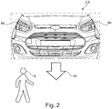
- a traffic scenario is shown in which a road user 8, in the present exemplary embodiment a pedestrian, crosses a path area 10 of a planned driving maneuver of the motor vehicle 2.
- the control unit 6 is designed to provide travel direction information FRI (see Figure 5 ) to read in representative of a planned driving maneuver of the motor vehicle 2 and to determine the route area 10. Furthermore, the control device 6 is designed to evaluate sensor data from the environment sensors in order to determine whether the road user 8 is in the path area 10.
- control device 6 determines a light activation data set LAD (see Figure 5 ) to control one or both lights 4a, 4b of the motor vehicle 2, at least by evaluating the direction of travel information FRI.
- the read-in travel direction information FRI is coded according to a predetermined code.
- the luminaire control data set LAD contains information representative of the planned driving maneuver of the motor vehicle 2 in which it will move through the path area 10.
- the control device 6 then controls the lights 4a, 4b in accordance with the lights control data set LAD.
- coded travel direction information FRI about the planned driving maneuver of the motor vehicle 2 is reproduced.
- the coded travel direction information FRI can be reproduced, for example, by changing a luminosity of the lights 4a, 4b.
- the lighting means 12 of the lights 4a, 4b which can be individually controlled, for example, can therefore emit light of different luminosity. It can be provided, for example, as in Figure 2 shown, to operate all lighting means 12 together with a maximum luminosity when a road user 8 was detected in the path area 10 in order to inform the road user 8 that he is in a danger area. If, on the other hand, there is no road user 8 in the path area 10, the lighting means 12 are operated, for example, as daytime running lights with a reduced luminosity.
- the coded travel direction information FRI can be reproduced, for example, by changing a light sequence of the lights 4a, 4b.
- the lighting means 12 of the lights 4a, 4b are activated individually and / or in groups in a chronologically predetermined sequence.
- direction information about the planned driving maneuver can be reproduced in accordance with the direction information FRI.
- a light sequence running from right to left can symbolize a left turn.
- Light sequences can also symbolize, for example, a standstill of the motor vehicle 2.
- the coded travel direction information FRI can be reproduced, for example, by changing a direction of illumination of the lights 4a, 4b.
- the lighting means 12 of the lights 4a, 4b are activated individually and / or in groups in a chronologically predetermined sequence. Individual lighting means 12 have different orientations, ie they emit light in different directions. A position of the registered road user 8 can thus be taken into account by emitting light in the direction of the detected road user 8.
- directional information about the planned driving maneuver can also be reproduced in accordance with the directional information FRI.
- the coded travel direction information FRI can be reproduced, for example, by changing a luminous color of the lights 4a, 4b.
- the lights 4a, 4b are shown. They have a plurality of lighting means 12, which in the present exemplary embodiment are LEDs.
- the lighting means 12 are assigned reflectors 14, which cause the light to be deflected and beam expansion of the light emitted by the respective lighting means 12.
- a lens 16 is arranged, which consists of an optically transparent but colored material.
- the material is colored turquoise, so that light passing through the lens 16 is colored turquoise.
- the daytime running lights are automatically activated when the motor vehicle 2 is started up and, in the present exemplary embodiment, are provided with a predetermined normal operating luminosity.
- control unit 6 reads in the travel direction information FRI representative of the planned driving maneuver of motor vehicle 2.
- the route area 10 is determined based on the travel direction information FRI.
- a logical variable V is assigned the value logical one. Otherwise, the logical variable V is assigned the value logical zero.
- the control device 6 reads in the logical variable V and in a further step S300 determines the light control data set LAD for controlling the lights 4a, 4b of the motor vehicle 2 if a road user 8 was detected in the path area 10, i.e. the logical variable V has the value logical one.
- the control device 6 evaluates the direction of travel information FRI and, if necessary, a detected position of the road user 8 in order to determine the light control data set LAD, with which the light intensity and / or light sequence and / or light direction and / or light color of the lights 4a, 4b or their light sources 12 can be specified.
- step S400 the lights 4a, 4b or their lighting means 12 are then controlled by the control device 6 in accordance with the light control data set LAD.
- the luminaire control data set LAD now causes a change to an operation with increased luminosity.
- the luminosity is increased from a first value to a second value, the first value being indicative of a normal operating luminosity and the second value being indicative of a luminosity that is greater than the normal operating luminosity.
- road user 8 in path area 10 changes to a luminosity that is greater than the normal operating luminosity.
- the luminaire control data set LAD - as already described - specifies a light sequence and / or a light direction and / or a light color.
- sequence of the steps can also be different. Furthermore, several steps can also be carried out simultaneously or simultaneously.
Landscapes
- Engineering & Computer Science (AREA)
- Mechanical Engineering (AREA)
- Aviation & Aerospace Engineering (AREA)
- Automation & Control Theory (AREA)
- General Physics & Mathematics (AREA)
- Physics & Mathematics (AREA)
- Remote Sensing (AREA)
- Radar, Positioning & Navigation (AREA)
- Health & Medical Sciences (AREA)
- Medical Informatics (AREA)
- Game Theory and Decision Science (AREA)
- Evolutionary Computation (AREA)
- Artificial Intelligence (AREA)
- Business, Economics & Management (AREA)
- Lighting Device Outwards From Vehicle And Optical Signal (AREA)
Description
- Die Erfindung betrifft ein Verfahren zum Betrieb eines selbstfahrenden Kraftfahrzeugs.
- Selbstfahrende Kraftfahrzeuge (manchmal auch autonome Landfahrzeuge genannt) sind Kraftfahrzeuge, die ohne Einflussnahme eines menschlichen Fahrers fahren, steuern und einparken können (hochautomatisiertes Fahren bzw. autonomes Fahren). Im Falle, dass keinerlei manuelles Steuern seitens eines Fahrers nötig ist, wird auch der Begriff Roboterauto verwendet. Der Fahrersitz kann unbesetzt bleiben; eventuell sind kein Lenkrad, Brems- und Fahrpedal vorhanden.
- Selbstfahrende Kraftfahrzeuge können mit Hilfe verschiedener Sensoren ihre Umgebung erfassen und aus den gewonnenen Informationen ihre Position und die anderer Verkehrsteilnehmer bestimmen, in Zusammenarbeit mit einer Navigationssoftware ein Fahrziel ansteuern und Kollisionen auf dem Weg dahin vermeiden.
- Derartige selbstfahrende Kraftfahrzeuge müssen mit ihrer Umgebung, insbesondere mit anderen Verkehrsteilnehmern, wie z.B. Fußgängern, kommunizieren können. Hierzu ist z.B. aus der
WO 2018 / 021063 A1 ist ein Beleuchtungssystem für ein selbstfahrendes Kraftfahrzeug bekannt, das auf ein Erfassen eines Verkehrsteilnehmers hin Lichtparameter verändert um so den Fußgänger darüber zu informieren, dass er vom selbstfahrenden Kraftfahrzeug erfasst wurde. - Jedoch werden keine Informationen darüber bereitgestellt, in welche Richtung das selbstfahrende Kraftfahrzeug seine Fahrt fortsetzen wird.
- Aus der
DE 10 2013 214 481 A1 ist eine Halteanzeigevorrichtung bekannt, die dazu ausgebildet ist, eine Anhalteabsicht eines ersten Verkehrsteilnehmers anzuzeigen, mit einer Straßenabschnitterfassungseinrichtung, die dazu ausgebildet ist, zu erfassen, dass ein zweiter Verkehrsteilnehmer einen Straßenabschnitt passieren möchte, den auch der erste Verkehrsteilnehmer passieren möchte; eine Vorrechtermittlungseinrichtung, die dazu ausgebildet ist, zu ermitteln, dass der zweite Verkehrsteilnehmer den Straßenabschnitt bevorrechtigt passieren darf; eine Hinweisausgabeeinrichtung, die dazu ausgebildet ist, einen Hinweises an den zweiten Verkehrsteilnehmer auszugeben, dass der erste Verkehrsteilnehmer erkannt hat, dass der zweite Verkehrsteilnehmer den Straßenabschnitt bevorrechtigt passieren darf, und dass der erste Verkehrsteilnehmer anhält, damit der zweite Verkehrsteilnehmer den Straßenabschnitt zuerst passieren kann. - Aus der
DE 10 2014 016 334 A1 ist eine Beleuchtungsvorrichtung für eine Außenlichtfunktion eines Kraftfahrzeugs mit einer Vielzahl von Segmenten bekannt, die jeweils mindestens ein Halbleiterlichtquellenelement aufweisen, sowie mit einer Steuervorrichtung zum Ansteuern der Vielzahl von Halbleiterlichtquellenelementen, wobei die Steuervorrichtung dazu ausgelegt ist, in Abhängigkeit eines durch das Kraftfahrzeug bereitgestellten aktuellen Werts eines Kraftfahrzeugparameters gemäß einer vorgebbaren Kennlinie mindestens einen Betriebsparameter der Beleuchtungsvorrichtung zu verändern. - Aus der
DE 10 2014 226 254 A1 _ist ein Verfahren zum Betreiben einer Signalisierungsvorrichtung eines insbesondere autonom oder teilautonom fahrenden/fahrbaren Kraftfahrzeugs bekannt, die wenigstens ein Signalisierungsmittel aufweist, das von außerhalb des Kraftfahrzeugs durch andere Verkehrsteilnehmer wahrnehmbar ist. Mittels einer Umfeldsensorik wird das Umfeld des Kraftfahrzeugs auf andere Verkehrsteilnehmer überwacht und in Abhängigkeit von einem erfassten Verkehrsteilnehmer wird die Signalisierungsvorrichtung angesteuert, um dem erfassten Verkehrsteilnehmer eine Information über ein weiteres Verhalten des Kraftfahrzeugs und/oder des erfassten Verkehrsteilnehmers anzuzeigen. - Aus der
US 2015 / 258928 A1 , derDE 20 2017 103902 U1 , derDE 10 2014 207399 A1 , derDE 10 2017 200781 A und derDE 10 2016 204877 A1 ist jeweils ein Verfahren zum Betrieb eines selbstfahrenden Kraftfahrzeugs bekannt, bei dem ,Fahrtrichtungsinformationen repräsentativ für ein geplantes Fahrmanöver des Kraftfahrzeugs eingelesen werden, ein Verkehrsteilnehmer im Wegebereich des geplanten Fahrmanövers unter Auswertung zumindest der Fahrtrichtungsinformationen erfasst wird, ein Leuchtenansteuerdatensatz zum Ansteuern zumindest einer als Frontscheinwerfer ausgebildeten Leuchte des Kraftfahrzeugs unter Auswertung zumindest der Fahrtrichtungsinformationen bestimmt wird, wenn ein Verkehrsteilnehmer im Wegebereich erfasst wurde, und die Leuchte gemäß dem Leuchtenansteuerdatensatz angesteuert wird. - Aus der
DE 20 2018 004776 A1 ein Tagwarnlicht bekannt. Das Tagwarnlicht kann ein Gefahrenkennzeichen, ein Strichmännchen, ein Radfahrer, eine geänderte Geometrie oder auch als Traktor ausgebildet sein. - Es besteht also Bedarf daran, Wege aufzuzeigen, wie andere Verkehrsteilnehmer, wie z.B. Fußgänger, über geplante Fahrmanöver des selbstfahrenden Kraftfahrzeugs informiert werden können.
- Die Aufgabe der Erfindung wird gelöst durch ein Verfahren zum Betrieb eines selbstfahrenden Kraftfahrzeugs, mit den Schritten:
- Einlesen von Fahrtrichtungsinformationen repräsentativ für ein geplantes Fahrmanöver des Kraftfahrzeugs,
- Erfassen von zumindest einem Verkehrsteilnehmer im Wegebereich des geplanten Fahrmanövers unter Auswertung zumindest der Fahrtrichtungsinform ationen,
- Bestimmen von einem Leuchtenansteuerdatensatz zum Ansteuern zumindest einer Leuchte des Kraftfahrzeugs, die als Frontscheinwerfer mit einem Tagfahrlicht ausgebildet ist, unter Auswertung zumindest der Fahrtrichtungsinformationen, wenn ein Verkehrsteilnehmer im Wegebereich erfasst wurde, und
- Ansteuern der Leuchte gemäß dem Leuchtenansteuerdatensatz, wobei mit dem Leuchtenansteuerdatensatz ein Wechsel zu einem Betrieb des Tagfahrlichts der Leuchte mit erhöhter Leuchtstärke bewirkt wird, wenn ein Verkehrsteilnehmer (8) im Wegebereich erfasst wurde.
- Die als Frontscheinwerfer ausgebildete Leuchte kann eine Mehrzahl von einzeln ansteuerbaren Leuchtmitteln, wie z.B. LEDs aufweisen, die mit dem Leuchtenansteuerdatensatz einzeln und/oder gruppenweise und/oder alle zusammen ansteuerbar sind. Die als Frontscheinwerfer ausgebildete Leuchte befindet sich an der Fahrzeugfront und strahlt Licht grundsätzlich in Vorwärtsfahrtrichtung des Kraftfahrzeugs ab. Im Rahmen des Bestimmens des Leuchtenansteuerdatensatz werden die erfassten Fahrtrichtungsinformationen gemäß einem vorbestimmten Code codiert. Es werden also durch das Ansteuern der Leuchte gemäß dem Leuchtenansteuerdatensatz kodierte Fahrtrichtungsinformationen über ein geplantes Fahrmanöver des Kraftfahrzeugs wiedergegeben. So werden andere Verkehrsteilnehmer, wie z.B. Fußgänger, über geplante Fahrmanöver des selbstfahrenden Kraftfahrzeugs informiert. Dadurch, dass erfasst wird, wenn sich ein Verkehrsteilnehmer im Wegebereich des geplanten Fahrmanövers befindet und nur dann der Leuchtenansteuerdatensatz erzeugt wird, wird vermieden, dass auf unbeteiligte Verkehrsteilnehmer reagiert wird. So können andere Verkehrsteilnehmer, wie z.B. Fußgänger, bedarfsgerecht über geplante Fahrmanöver des selbstfahrenden Kraftfahrzeugs informiert werden, ohne dass hierzu zusätzliche Leuchteinrichtungen, wie weitere Leuchten, notwendig sind.
- Es wird die Leuchtstärke ausgehend von einem ersten Wert auf einen zweiten Wert angehoben, wobei der erste Wert indikativ für eine Normalbetriebsleuchtstärke ist und der zweite Wert indikativ für eine Leuchtstärke ist, die größer als die Normalbetriebsleuchtstärke ist. So können besonders leicht einfach von anderen Verkehrsteilnehmern, wie z.B. von Fußgängern, wahrnehmbare Warnsignale erzeugt werden
- Unter einem Tagfahrlicht wird eine Fahrzeugbeleuchtung verstanden, die die Sichtbarkeit des Kraftfahrzeugs am Tage für andere Verkehrsteilnehmer verbessern und so Unfälle durch Übersehen werden verringern soll. Das Tagfahrlicht kann von Tagfahrleuchten bereitgestellt werden. Derartige Tagfahrleuchten sind lichtschwache, verbrauchsarme und langlebige Leuchten, die weniger Leuchtkraft haben als das Abblendlicht, aber viermal so intensiv leuchten wie die vorderen weißen Umrissleuchten (das ist oft auch das Standlicht). Die technische Norm Nr. 87 der UNO-Wirtschaftskommission für Europa (ECE) sieht für Tagfahrleuchten eine Lichtstärke von mindestens 400 Candela pro Leuchte vor. Das Tagfahrlicht wird mit Inbetriebnahme des Kraftfahrzeugs automatisch aktiviert und mit einer vorbestimmten Normalbetriebsleuchtstärke bereitgestellt. Wird ein Verkehrsteilnehmer im Wegebereich erfasst erfolgt ein Wechsel zu einer Leuchtstärke, die größer als die Normalbetriebsleuchtstärke ist. Somit erfolgt eine Doppelnutzung des Tagfahrlichts, nämlich als eigentliches Tagfahrlicht und zum Erzeugen von Warnhinweisen.
- Gemäß einer Ausführungsform wird mit dem Leuchtenansteuerdatensatz eine Leuchtstärke vorgegeben. Die z.B. einzeln ansteuerbaren Leuchtmittel der Leuchte können also Licht unterschiedlicher Leuchtstärke abgeben. So können z.B. Warnsignale für andere Verkehrsteilnehmer, wie z.B. Fußgänger, erzeugt werden.
- Gemäß einer weiteren Ausführungsform wird mit dem Leuchtenansteuerdatensatz eine Leuchtfolge vorgegeben. Die z.B. einzeln ansteuerbaren Leuchtmittel der Leuchte können einzeln und/oder gruppenweise in einer zeitlich vorbestimmten Reihenfolge aktiviert werden. Derartige, zeitlich variable Leuchtfolgen können besonders einfach von anderen Verkehrsteilnehmern, wie z.B. Fußgängern, wahrgenommen werden.
- Gemäß einer weiteren Ausführungsform wird mit dem Leuchtenansteuerdatensatz eine Leuchtrichtung vorgegeben. Die z.B. einzeln ansteuerbaren Leuchtmittel der Leuchte können einzeln und/oder gruppenweise in einer zeitlich vorbestimmten Reihenfolge aktiviert werden. Dabei können die einzelnen Leuchtmittel unterschiedliche Ausrichtungen aufweisen, d.h. sie emittieren Licht in unterschiedliche Richtungen. So kann eine Position eines erfassten Verkehrsteilnehmers, wie z.B. eines Fußgängers, berücksichtigt werden, indem z.B. Licht in Richtung des erfassten Verkehrsteilnehmers, wie z.B. des Fußgängers, emittiert wird. So kann die Wahrnehmbarkeit nochmals verbessert werden.
- Gemäß einer weiteren Ausführungsform wird mit dem Leuchtenansteuerdatensatz eine Leuchtfarbe vorgegeben. Die z.B. einzeln ansteuerbaren Leuchtmittel der Leuchte können einzeln und/oder gruppenweise in Lichtausbreitungsrichtung hinter einer farbigen Linse angeordnet sein, während andere der ansteuerbaren Leuchtmittel sich hinter einer nicht eingefärbten Linse befinden. Durch das Aktivieren der ansteuerbaren Leuchtmittel hinter der farbigen Linse kann die Leuchtfarbe verändert werden. So kann die Wahrnehmbarkeit ebenfalls nochmals verbessert werden.
- Ferner gehören zur Erfindung ein Computerprogrammprodukt und ein Steuergerät.
- Es wird nun die Erfindung anhand einer Zeichnung erläutert. Es zeigen:
-
Figur 1 in schematischer Darstellung eine Vorderansicht eines Kraftfahrzeugs. -
Figur 2 in schematischer Darstellung ein Verkehrsszenario mit einem weiteren Verkehrsteilnehmer. -
Figur 3 in schematischer Darstellung ein weiteres Verkehrsszenario mit einem weiteren Verkehrsteilnehmer. -
Figur 4 in schematischer Darstellung eine Leuchte des inFigur 1 gezeigten Kraftfahrzeugs. -
Figur 5 in schematischer Darstellung einen Verfahrensablauf zum Betrieb der in denFiguren 1 bis 3 gezeigten Kraftfahrzeuge. - Es wird zunächst auf
Figur 1 Bezug genommen. - Dargestellt ist ein Kraftfahrzeug 2, das im vorliegenden Ausführungsbeispiel als PKW ausgebildet ist. Ferner ist das Kraftfahrzeug 2 im vorliegenden Ausführungsbeispiel als selbstfahrendes Kraftfahrzeug ausgebildet, das ohne Einflussnahme eines menschlichen Fahrers fahren, steuern und einparken kann. Hierzu weist das Kraftfahrzeug 2 verschiedene Umfeldsensoren zur Umgebungserfassung auf und kann aus den gewonnenen Informationen seine Position und die anderer Verkehrsteilnehmer bestimmen, in Zusammenarbeit mit einer Navigationssoftware ein Fahrziel ansteuern und Kollisionen auf dem Weg dorthin vermeiden.
- Das Kraftfahrzeug 2 weist eine Fahrzeugbeleuchtung auf. Unter der Fahrzeugbeleuchtung werden lichttechnische Einrichtungen von Kraftfahrzeugen verstanden, die notwendig sind, um bei Dämmerung, Dunkelheit oder bei schlechten Witterungsverhältnissen gesehen zu werden.
- Die Fahrzeugbeleuchtung weist im vorliegenden Ausführungsbeispiel wie bei mehrspurigen Kraftfahrzeugen 2 üblich zwei Leuchten 4a, 4b auf. Abweichend vom vorliegenden Ausführungsbeispiel kann das Kraftfahrzeug 2 auch einspurig ausgebildet sein und dann wie üblich nur eine Leuchte 4a, 4b aufweisen
- Die Leuchten 4a, 4b sind als Frontscheinwerfer ausgebildet, d.h. sie befinden sich an der Fahrzeugfront des Kraftfahrzeugs 2 und strahlen Licht grundsätzlich in Vorwärtsfahrtrichtung des Kraftfahrzeugs 2 ab.
- Im vorliegenden Ausführungsbeispiel stellen die Leuchten 4a, 4b ein Fernlicht, ein Abblendlicht, ein Standlicht sowie ein Tagfahrlicht bereit. Dabei wird unter einem Tagfahrlicht eine Fahrzeugbeleuchtung verstanden, die die Sichtbarkeit des Kraftfahrzeugs am Tage für andere Verkehrsteilnehmer verbessern und so Unfälle durch Übersehen werden verringern soll. Das Tagfahrlicht kann von Tagfahrleuchten bereitgestellt werden. Derartige Tagfahrleuchten sind lichtschwache, verbrauchsarme und langlebige Leuchten, die weniger Leuchtkraft haben als das Abblendlicht, aber viermal so intensiv leuchten wie die vorderen weißen Umrissleuchten (das ist oft auch das Standlicht). Die technische Norm Nr. 87 der UNO-Wirtschaftskommission für Europa (ECE) sieht für Tagfahrleuchten eine Lichtstärke von mindestens 400 Candela pro Leuchte vor. Zusätzlich kann die Fahrzeugbeleuchtung auch ein Parklicht und/oder ein Kurvenlicht bereitstellen sowie und/oder Nebelscheinwerfer aufweisen. In der in
Figur 1 gezeigten Darstellung stellen die Leuchten 4a, 4b ein Tagfahrlicht mit einer reduzierten Leuchtstärke bereit. - Die Leuchten 4a, 4b weisen jeweils eine Mehrzahl von einzeln ansteuerbaren Leuchtmittel 12 (siehe
Figur 4 ) auf, die - wie dies später noch detailliert erläutert wird - einzeln und/oder gruppenweise und/oder alle zusammen ansteuerbar sind. Bei den Leuchtmitteln 12 handelt es sich im vorliegenden Ausführungsbeispiel um LEDs. Mit anderen Worten, die Leuchten 4a, 4b sind im vorliegenden Ausführungsbeispiel jeweils als elektrisch gesteuerte LED-Scheinwerfer (auch Matrix-LED-Scheinwerfer) ausgebildet, die von einem Steuergerät 6 angesteuert werden. Hierzu und für die nachfolgend beschriebenen Aufgaben und/oder Funktionen kann das Steuergerät 6 Hard- und/oder Software-Komponenten aufweisen. - Es wird nun zusätzlich auf
Figur 2 Bezug genommen. - Dargestellt ist ein Verkehrsszenario, in dem ein Verkehrsteilnehmer 8, im vorliegenden Ausführungsbeispiel ein Fußgänger, einen Wegebereich 10 eines geplanten Fahrmanövers des Kraftfahrzeugs 2 kreuzt.
- Das Steuergerät 6 ist dazu ausgebildet, Fahrtrichtungsinformationen FRI (siehe
Figur 5 ) repräsentativ für ein geplantes Fahrmanöver des Kraftfahrzeugs 2 einzulesen und den Wegebereich 10 zu bestimmen. Des Weiteren ist das Steuergerät 6 dazu ausgebildet, Sensordaten der Umfeldsensoren auszuwerten, um zu bestimmen, ob sich der Verkehrsteilnehmer 8 in dem Wegebereich 10 befindet. - Wenn ein Verkehrsteilnehmer 8 im Wegebereich 10 erfasst wurde bestimmt das Steuergerät 6 einen Leuchtenansteuerdatensatz LAD (siehe
Figur 5 ) zum Ansteuern einer oder beider Leuchten 4a, 4b des Kraftfahrzeugs 2 zumindest unter Auswertung der Fahrtrichtungsinformationen FRI. - Dabei werden im Rahmen des Bestimmens des Leuchtenansteuerdatensatz LAD die eingelesenen Fahrtrichtungsinformationen FRI gemäß einem vorbestimmten Code codiert. Mit anderen Worten, der Leuchtenansteuerdatensatz LAD enthält Informationen repräsentativ für das geplante Fahrmanöver des Kraftfahrzeugs 2, bei dem es sich durch den Wegebereich 10 bewegen wird.
- Das Steuergerät 6 steuert dann die Leuchten 4a, 4b gemäß dem Leuchtenansteuerdatensatz LAD an. Es werden also durch das Ansteuern der Leuchten 4a, 4b gemäß dem Leuchtenansteuerdatensatz LAD kodierte Fahrtrichtungsinformationen FRI über das geplante Fahrmanöver des Kraftfahrzeugs 2 wiedergegeben.
- Die kodierten Fahrtrichtungsinformationen FRI können z.B. wiedergegeben werden, in dem eine Leuchtstärke der Leuchten 4a, 4b verändert wird. Die z.B. einzeln ansteuerbaren Leuchtmittel 12 der Leuchten 4a, 4b können also Licht unterschiedlicher Leuchtstärke abgeben. Es kann z.B. vorgesehen sein, wie in
Figur 2 dargestellt, alle Leuchtmittel 12 zusammen mit einer maximalen Leuchtstärke zu betreiben, wenn ein Verkehrsteilnehmer 8 im Wegebereich 10 erfasst wurde um so den Verkehrsteilnehmer 8 darüber zu informieren, dass er sich in einem Gefahrenbereich befindet. Befindet sich hingegen kein Verkehrsteilnehmer 8 im Wegebereich 10 werden die Leuchtmittel 12 z.B. als Tagfahrlicht mit einer reduzierten Leuchtstärke betrieben. - Zusätzlich können die kodierten Fahrtrichtungsinformationen FRI z.B. wiedergegeben werden, in dem eine Leuchtfolge der Leuchten 4a, 4b verändert wird. Hierzu werden die Leuchtmittel 12 der Leuchten 4a, 4b einzeln und/oder gruppenweise in einer zeitlich vorbestimmten Reihenfolge aktiviert. So können z.B. Richtungsinformationen über das geplante Fahrmanöver gemäß den Fahrtrichtungsinformationen FRI wiedergegeben werden. Z.B. kann eine von rechts nach links verlaufende Leuchtfolge ein Linksabbiegen symbolisieren. Auch können Leuchtfolgen z.B. einen Stillstand des Kraftfahrzeugs 2 symbolisieren.
- Zusätzlich können die kodierten Fahrtrichtungsinformationen FRI z.B. wiedergegeben werden, in dem eine Leuchtrichtung der Leuchten 4a, 4b verändert wird. Die Leuchtmittel 12 der Leuchten 4a, 4b werden hierzu einzeln und/oder gruppenweise in einer zeitlich vorbestimmten Reihenfolge aktiviert. Einzelne Leuchtmittel 12 weisen dabei unterschiedliche Ausrichtungen auf, d.h. sie emittieren Licht in unterschiedliche Richtungen. So kann eine Position des erfassten Verkehrsteilnehmers 8, berücksichtigt werden, indem Licht in Richtung des erfassten Verkehrsteilnehmers 8 emittiert wird. Es können aber auch so z.B. Richtungsinformationen über das geplante Fahrmanöver gemäß den Fahrtrichtungsinformationen FRI wiedergegeben werden.
- Es wird nun zusätzlich auf
Figur 3 Bezug genommen. - Zusätzlich können die kodierten Fahrtrichtungsinformationen FRI z.B. wiedergegeben werden, in dem eine Leuchtfarbe der Leuchten 4a, 4b verändert wird.
- Es wird nun zusätzlich auf
Figur 4 Bezug genommen, um den Aufbau der Leuchte 4a, 4b zu erläutern. - Dargestellt sind die Leuchten 4a, 4b. Sie weisen eine Mehrzahl von Leuchtmitteln 12 auf, die im vorliegenden Ausführungsbeispiel LEDs sind.
- Den Leuchtmitteln 12 sind Reflektoren 14 zugeordnet, die eine Lichtumlenkung und Strahlaufweitung des von den jeweiligen Leuchtmitteln 12 emittierten Lichts bewirken.
- In Lichtausbreitungsrichtung hinter den Reflektoren 14 ist eine Linse 16 angeordnet, die aus einem optisch durchlässigen, aber eingefärbten Material besteht. Im vorliegenden Ausführungsbeispiel ist das Material Türkis eingefärbt, so dass durch die Linse 16 hindurchtretendes Licht Türkis eingefärbt wird. So kann durch Aktivieren der Leuchtmittel 12 hinter der farbigen Linse 16 die Leuchtfarbe verändert werden.
- Es wird nun unter zusätzlicher Bezugnahme auf die
Figur 5 ein Verfahrensablauf zum Betrieb des Kraftfahrzeugs 2 erläutert. - Das Tagfahrlicht wird mit Inbetriebnahme des Kraftfahrzeugs 2 automatisch aktiviert und im vorliegenden Ausführungsbeispiel mit einer vorbestimmten Normalbetriebsleuchtstärke bereitgestellt.
- In einem ersten Schritt S100 liest das Steuergerät 6 die Fahrtrichtungsinformationen FRI repräsentativ für das geplante Fahrmanöver des Kraftfahrzeugs 2 ein. Basierend auf den Fahrtrichtungsinformationen FRI wird der Wegebereich 10 bestimmt.
- In einem weiteren Schritt S200 wird durch Auswerten von Sensordaten der Umfeldsensoren des Kraftfahrzeugs 2 bestimmt, ob sich der Verkehrsteilnehmer 8 in dem Wegebereich 10 befindet, durch den sich das Kraftfahrzeug 2 gemäß dem geplanten Fahrmanöver bewegen wird. Wenn sich der Verkehrsteilnehmer 8 in dem Wegebereich 10 befindet wird einer logischen Variablen V der Wert logisch Eins zugewiesen. Andernfalls wird der logischen Variablen V der Wert logisch Null zugewiesen.
- Das Steuergerät 6 liest die logische Variable V ein und bestimmt in einem weiteren Schritt S300 den Leuchtenansteuerdatensatz LAD zum Ansteuern der Leuchten 4a, 4b des Kraftfahrzeugs 2 wenn ein Verkehrsteilnehmer 8 im Wegebereich 10 erfasst wurde, d.h. die logische Variable V den Wert logisch Eins hat. Dabei wertet das Steuergerät 6 die Fahrtrichtungsinformationen FRI sowie gegebenenfalls eine erfasste Position des Verkehrsteilnehmers 8 aus um den Leuchtenansteuerdatensatz LAD zu bestimmen, mit dem die Leuchtstärke und/oder Leuchtfolge und/oder Leuchtrichtung und/oder Leuchtfarbe der Leuchten 4a, 4b bzw. deren Leuchtmittel 12 vorgegeben werden kann.
- In einem weiteren Schritt S400 werden dann die Leuchten 4a, 4b bzw. deren Leuchtmittel 12 von dem Steuergerät 6 gemäß dem Leuchtenansteuerdatensatz LAD angesteuert.
- Durch den Leuchtenansteuerdatensatz LAD wird nun ein Wechsel zu einem Betrieb mit erhöhter Leuchtstärke bewirkt. Hierbei wird die Leuchtstärke ausgehend von einem ersten Wert auf einen zweiten Wert angehoben, wobei der erste Wert indikativ für eine Normalbetriebsleuchtstärke ist und der zweite Wert indikativ für eine Leuchtstärke ist, die größer als die Normalbetriebsleuchtstärke ist. Mit anderen Worten, auf das Erfassen des Verkehrsteilnehmers 8 im Wegebereich 10 erfolgt im vorliegenden Ausführungsbeispiel ein Wechsel zu einer Leuchtstärke, die größer als die Normalbetriebsleuchtstärke ist.
- Zusätzlich kann vorgesehen sein, dass der Leuchtenansteuerdatensatz LAD - wie schon beschreiben - eine Leuchtfolge und/oder eine Leuchtrichtung und/oder eine Leuchtfarbe vorgibt.
- Abweichend vom vorliegenden Ausführungsbeispiel kann die Reihenfolge der Schritte auch eine andere sein. Ferner können mehrere Schritte auch zeitgleich bzw. simultan ausgeführt werden.
- So können andere Verkehrsteilnehmer 8, wie z.B. Fußgänger, bedarfsgerecht über geplante Fahrmanöver des Kraftfahrzeugs 2 informiert werden, ohne dass hierzu zusätzliche Leuchteinrichtung, wie weitere Leuchten, notwendig sind.
-
- 2
- Kraftfahrzeug
- 4a
- Leuchte
- 4b
- Leuchte
- 6
- Steuergerät
- 8
- Verkehrsteilnehmer
- 10
- Wegebereich
- 12
- Leuchtmittel
- 14
- Reflektoren
- 16
- Linse
- FRI
- Fahrtrichtungsinformationen
- LAD
- Leuchtenansteuerdatensatz
- V
- logische Variable
Claims (11)
- Verfahren zum Betrieb eines selbstfahrenden Kraftfahrzeugs (2), mit den Schritten:(S100) Einlesen von Fahrtrichtungsinformationen (FRI) repräsentativ für ein geplantes Fahrmanöver des Kraftfahrzeugs (2),(S200) Erfassen von zumindest einem Verkehrsteilnehmer (8) im Wegebereich (10) des geplanten Fahrmanövers unter Auswertung zumindest der Fahrtrichtungsinformationen (FRI),(S300) Bestimmen von einem Leuchtenansteuerdatensatz (LAD) zum Ansteuern zumindest einer Leuchte (4a, 4b) des Kraftfahrzeugs (2), die als Frontscheinwerfer mit einem Tagfahrlicht ausgebildet ist, unter Auswertung zumindest der Fahrtrichtungsinformationen (FRI), wenn ein Verkehrsteilnehmer (8) im Wegebereich (10) erfasst wurde, und(S400) Ansteuern der Leuchte (4a, 4b) gemäß dem Leuchtenansteuerdatensatz (LAD), dadurch gekennzeichnet, dass mit dem Leuchtenansteuerdatensatz (LAD) ein Wechsel zu einem Betrieb des Tagfahrlichts der Leuchte (4a, 4b) mit erhöhter Leuchtstärke bewirkt wird, wenn ein Verkehrsteilnehmer (8) im Wegebereich (10) erfasst wurde.
- Verfahren nach Anspruch 1, wobei mit dem Leuchtenansteuerdatensatz (LAD) eine Leuchtstärke vorgegeben wird.
- Verfahren nach Anspruch 1 oder 2, wobei mit dem Leuchtenansteuerdatensatz (LAD) eine Leuchtfolge vorgegeben wird.
- Verfahren nach einem der Ansprüche 1 bis 3, wobei mit dem Leuchtenansteuerdatensatz (LAD) eine Leuchtrichtung vorgegeben wird.
- Verfahren nach einem der Ansprüche 1 bis 4, wobei mit dem Leuchtenansteuerdatensatz (LAD) eine Leuchtfarbe vorgegeben wird.
- Computerprogrammprodukt, umfassend Befehle, die bei der Ausführung des Programms durch einen Computer diesen veranlassen, das Verfahren nach einem der Ansprüche 1 bis 5 auszuführen.
- Steuergerät (6) zum Betrieb eines selbstfahrenden Kraftfahrzeugs (2), wobei das Steuergerät (6) dazu ausgebildet ist Fahrtrichtungsinformationen (FRI) repräsentativ für ein geplantes Fahrmanöver des Kraftfahrzeugs (2) einzulesen, zumindest einem Verkehrsteilnehmer (8) im Wegebereich (10) des geplanten Fahrmanövers unter Auswertung zumindest der Fahrtrichtungsinformationen (FRI) zu erfassen, einen Leuchtenansteuerdatensatz (LAD) zum Ansteuern zumindest einer Leuchte (4a, 4b) des Kraftfahrzeugs, die als Frontscheinwerfer mit einem Tagfahrlicht ausgebildet ist, unter Auswertung zumindest der Fahrtrichtungsinformationen (FRI) zu bestimmen, wenn ein Verkehrsteilnehmer (8) im Wegebereich (10) erfasst wurde, und die Leuchte (4a, 4b) gemäß dem Leuchtenansteuerdatensatz (LAD) anzusteuern, dadurch gekennzeichnet, dass mit dem Leuchtenansteuerdatensatz (LAD) ein Wechsel zu einem Betrieb des Tagfahrlichts der Leuchte (4a, 4b) mit erhöhter Leuchtstärke bewirkt wird, wenn ein Verkehrsteilnehmer (8) im Wegebereich (10) erfasst wurde.
- Steuergerät (6) nach Anspruch 7, wobei mit dem Leuchtenansteuerdatensatz (LAD) eine Leuchtstärke vorgebbar ist.
- Steuergerät (6) nach Anspruch 7 oder 8, wobei mit dem Leuchtenansteuerdatensatz (LAD) eine Leuchtfolge vorgebbar ist
- Steuergerät (6) nach einem der Ansprüche 7 bis 9, wobei mit dem Leuchtenansteuerdatensatz (LAD) eine Leuchtrichtung vorgebbar ist.
- Steuergerät (6) nach einem der Ansprüche 7 bis 10, wobei mit dem Leuchtenansteuerdatensatz (LAD) eine Leuchtfarbe vorgebbar ist.
Applications Claiming Priority (1)
| Application Number | Priority Date | Filing Date | Title |
|---|---|---|---|
| DE102019201666.9A DE102019201666A1 (de) | 2019-02-08 | 2019-02-08 | Verfahren zum Betrieb eines selbstfahrenden Kraftfahrzeugs |
Publications (2)
| Publication Number | Publication Date |
|---|---|
| EP3693220A1 EP3693220A1 (de) | 2020-08-12 |
| EP3693220B1 true EP3693220B1 (de) | 2021-07-07 |
Family
ID=68766519
Family Applications (1)
| Application Number | Title | Priority Date | Filing Date |
|---|---|---|---|
| EP19213026.8A Active EP3693220B1 (de) | 2019-02-08 | 2019-12-02 | Verfahren zum betrieb eines selbstfahrenden kraftfahrzeugs |
Country Status (4)
| Country | Link |
|---|---|
| US (1) | US11590885B2 (de) |
| EP (1) | EP3693220B1 (de) |
| CN (1) | CN111546982A (de) |
| DE (1) | DE102019201666A1 (de) |
Families Citing this family (1)
| Publication number | Priority date | Publication date | Assignee | Title |
|---|---|---|---|---|
| DE102022211861A1 (de) | 2022-11-09 | 2024-05-16 | Volkswagen Aktiengesellschaft | Verfahren zum Informieren eines weiteren Verkehrsteilnehmers mittels eines autonomen Kraftfahrzeugs, autonomes Kraftfahrzeug sowie System |
Family Cites Families (43)
| Publication number | Priority date | Publication date | Assignee | Title |
|---|---|---|---|---|
| US6587573B1 (en) | 2000-03-20 | 2003-07-01 | Gentex Corporation | System for controlling exterior vehicle lights |
| US6084507A (en) | 1998-11-30 | 2000-07-04 | Butler; Isaac | Truck turning safety gate |
| US9955551B2 (en) * | 2002-07-12 | 2018-04-24 | Yechezkal Evan Spero | Detector controlled illuminating system |
| MXPA02009331A (es) | 2002-09-24 | 2004-03-26 | San Juan Torres Carlos | Sistema de luces indicadoras del status del movimiento de vehiculos automotores. |
| US9384660B2 (en) | 2005-05-27 | 2016-07-05 | David A. Fossier | Mirror alert with projected message |
| EP2232458B1 (de) | 2007-12-13 | 2018-06-27 | Continental Teves AG & Co. oHG | Verfahren und vorrichtung zur unterstützung eines fahrzeugbedieners |
| US10539311B2 (en) * | 2008-04-14 | 2020-01-21 | Digital Lumens Incorporated | Sensor-based lighting methods, apparatus, and systems |
| US8358074B2 (en) | 2009-02-26 | 2013-01-22 | GM Global Technology Operations LLC | Daytime running lamp activation control methods and apparatus |
| US9315146B2 (en) | 2010-04-13 | 2016-04-19 | Kory Patrick Purks | Vehicle turn signalling apparatuses with laser devices, light projection circuits, and related electromechanical actuators |
| DE102010034853A1 (de) | 2010-08-18 | 2012-02-23 | Gm Global Technology Operations Llc (N.D.Ges.D. Staates Delaware) | Kraftfahrzeug mit Digitalprojektoren |
| DE102011051152A1 (de) | 2011-06-17 | 2012-12-20 | Hella Kgaa Hueck & Co. | Verfahren zum Betrieb einer Leuchte sowie Leuchte für ein Fahrzeug |
| US8831849B2 (en) | 2012-02-13 | 2014-09-09 | Toyota Motor Engineering & Manufacturing North America, Inc. | System and method for traffic signal recognition |
| JP2013222553A (ja) | 2012-04-13 | 2013-10-28 | Koito Mfg Co Ltd | 車両用灯具 |
| US20140247160A1 (en) | 2013-03-01 | 2014-09-04 | Sandra J. Glascock | Systems and methods for traffic signal warning |
| US9321395B2 (en) | 2013-04-26 | 2016-04-26 | Ford Global Technologies, Llc | Vehicle puddle lamp assembly generating animated image and method |
| ES2520341B1 (es) | 2013-05-07 | 2015-08-18 | José María Millet Sancho | Sistema de alerta anti atropellos para vehículos |
| DE102013214481A1 (de) * | 2013-07-24 | 2015-01-29 | Bayerische Motoren Werke Aktiengesellschaft | Vorrangassistent |
| CN203472784U (zh) | 2013-08-19 | 2014-03-12 | 北京汽车股份有限公司 | 一种行人安全警示装置及机动车 |
| US20150058127A1 (en) | 2013-08-26 | 2015-02-26 | International Business Machines Corporation | Directional vehicular advertisements |
| US9481287B2 (en) | 2014-01-21 | 2016-11-01 | Harman International Industries, Inc. | Roadway projection system |
| JP6137001B2 (ja) * | 2014-03-14 | 2017-05-31 | 株式会社デンソー | 車載装置 |
| DE102014207399A1 (de) * | 2014-04-17 | 2015-10-22 | Bayerische Motoren Werke Aktiengesellschaft | Vorrichtung und Verfahren zur Bewältigung von Unfallrisikosituationen mit Lebewesen |
| US9318021B2 (en) | 2014-06-26 | 2016-04-19 | Jassem M. Al-Jasem Al-Qaneei | Vehicle mounted traffic light and system |
| DE102014011811B4 (de) | 2014-08-09 | 2018-08-09 | Audi Ag | Informieren eines Verkehrsteilnehmers über eine autopilotgesteuerte Fahrt |
| DE102014016334A1 (de) * | 2014-11-05 | 2016-05-12 | Audi Ag | Beleuchtungsvorrichtung für eine Außenlichtfunktion eines Kraftfahrzeugs und Verfahren zur Ansteuerung einer derartigen Beleuchtungsvorrichtung |
| DE102014226254A1 (de) * | 2014-12-17 | 2016-06-23 | Robert Bosch Gmbh | Verfahren zum Betreiben eines insbesondere autonom oder teilautonom fahrenden/fahrbaren Kraftfahrzeugs, Signalisierungsvorrichtung, Kraftfahrzeug |
| CN110450701A (zh) | 2015-01-13 | 2019-11-15 | 麦克赛尔株式会社 | 车辆 |
| US20170011628A1 (en) | 2015-07-10 | 2017-01-12 | Continental Automotive Systems, Inc. | Traffic light replicator in a bus or truck |
| US9804599B2 (en) * | 2015-11-04 | 2017-10-31 | Zoox, Inc. | Active lighting control for communicating a state of an autonomous vehicle to entities in a surrounding environment |
| US9810394B2 (en) | 2015-11-13 | 2017-11-07 | Ford Global Technologies, Llc | Vehicular signal and daytime running light assemblies with uniform illumination |
| US10134280B1 (en) | 2016-02-23 | 2018-11-20 | Taehyun You | Vehicular notifications |
| KR101826408B1 (ko) | 2016-03-03 | 2018-03-22 | 엘지전자 주식회사 | 디스플레이 장치 및 이를 포함하는 차량 |
| DE102016204877A1 (de) * | 2016-03-23 | 2017-09-28 | Ford Global Technologies, Llc | Verfahren zum Betreiben eines Fahrassistenzsystems zur Durchführung eines autonomen oder teilautonomen Fahrmanövers eines Fahrzeugs und derartiges Fahrassistenzsystem |
| US9771021B1 (en) | 2016-05-03 | 2017-09-26 | Toyota Motor Engineering & Manufacturing North America, Inc. | Pedestrian marking systems |
| AT15827U1 (de) * | 2016-07-07 | 2018-07-15 | Zkw Group Gmbh | Beleuchtungssystem zur Kommunikation zwischen autonomen Fahrzeugen und anderen Verkehrsteilnehmern |
| JP7045993B2 (ja) | 2016-07-29 | 2022-04-01 | 株式会社小糸製作所 | 車両用照明システム、車両システム及び車両 |
| KR102457029B1 (ko) * | 2016-09-20 | 2022-10-24 | 이노비즈 테크놀로지스 엘티디 | Lidar 시스템 및 방법 |
| US10657819B2 (en) | 2016-09-21 | 2020-05-19 | Apple Inc. | External communication for vehicles |
| CN206136392U (zh) | 2016-10-19 | 2017-04-26 | 重庆莱锐达科技有限责任公司 | Led可调颜色日间行车灯 |
| KR20170001677A (ko) | 2016-12-15 | 2017-01-04 | 김원호 | 자동차 전면 바닥 신호등 램프 |
| DE102017200781A1 (de) * | 2017-01-19 | 2018-07-19 | Bayerische Motoren Werke Aktiengesellschaft | Vorrichtung, Fortbewegungsmittel und Verfahren zur Vermeidung von Verkehrsunfällen |
| KR101908309B1 (ko) | 2017-04-12 | 2018-10-16 | 엘지전자 주식회사 | 차량용 램프 |
| DE202018004776U1 (de) * | 2018-10-16 | 2018-11-12 | Christoph Voll | Tagfahrwarnlicht |
-
2019
- 2019-02-08 DE DE102019201666.9A patent/DE102019201666A1/de active Pending
- 2019-12-02 EP EP19213026.8A patent/EP3693220B1/de active Active
-
2020
- 2020-02-02 CN CN202010078104.XA patent/CN111546982A/zh active Pending
- 2020-02-04 US US16/781,095 patent/US11590885B2/en active Active
Also Published As
| Publication number | Publication date |
|---|---|
| EP3693220A1 (de) | 2020-08-12 |
| US11590885B2 (en) | 2023-02-28 |
| CN111546982A (zh) | 2020-08-18 |
| US20200254924A1 (en) | 2020-08-13 |
| DE102019201666A1 (de) | 2020-08-13 |
Similar Documents
| Publication | Publication Date | Title |
|---|---|---|
| EP2562039B1 (de) | Verfahren und Vorrichtung zum Ändern einer Lichtaussendung zumindest eines Scheinwerfers eines Fahrzeugs | |
| DE102009009472B4 (de) | Verfahren zum Unterstützen eines Fahrers eines Fahrzeugs und Fahrerassistenzsystem für ein Fahrzeug | |
| DE102014226254A1 (de) | Verfahren zum Betreiben eines insbesondere autonom oder teilautonom fahrenden/fahrbaren Kraftfahrzeugs, Signalisierungsvorrichtung, Kraftfahrzeug | |
| DE102018206087B4 (de) | Verfahren zur Kommunikation eines Kraftfahrzeugs mit einem Verkehrsteilnehmer sowie Kraftfahrzeug zur Durchführung des Verfahrens | |
| DE112016006168B4 (de) | Informationsanzeigeeinrichtung und informationsanzeigeverfahren | |
| EP3781439B1 (de) | Verfahren zur kommunikation eines kraftfahrzeugs mit einem verkehrsteilnehmer sowie kraftfahrzeug zur durchführung des verfahrens | |
| EP3411267B1 (de) | Kraftfahrzeug | |
| EP2562044B1 (de) | Verfahren zur Steuerung einer Lichtaussendung eines Scheinwerfers eines Fahrzeugs | |
| DE102012200431B4 (de) | Verfahren zur Bestimmung eines Vorliegens einer Kreuzung in einem von einem Fahrzeug befahrenen Straßenverlauf | |
| DE102008003936A1 (de) | Vorrichtung zur Ausgabe von Warnmeldungen für ein Kraftfahrzeug | |
| EP2700536A2 (de) | Verfahren zum Betreiben eines Scheinwerfersystems und Scheinwerfersystem für ein Fahrzeug | |
| DE102013001276A1 (de) | Verfahren zur Steuerung eines Abbiegelichts in einem Kraftfahrzeug | |
| DE102011119558A1 (de) | Verfahren zur parameterabhängigen Ansteuerung einer Leuchteinheit in einem Kraftfahrzeug | |
| DE102016124933A1 (de) | Vorrichtung, Verfahren, Computerprogrammprodukt und computerlesbares Medium zur visuellen Information eines Fahrzeugführers eines Kraftfahrzeugs | |
| EP1346877B1 (de) | Vorrichtung zur Anzeige einer Gefahrensituation bei einem Spurwechsel in einem Kraftfahrzeug | |
| WO2017134108A1 (de) | Kraftfahrzeug | |
| WO2016110365A1 (de) | Verfahren und fahrerassistenzsystem zum unterstützen eines fahrers eines fahrzeugs | |
| DE102007054048A1 (de) | Verfahren und Vorrichtung für eine Fahrlichtsteuerung eines Fahrzeugs | |
| DE102018206042A1 (de) | Verfahren zur Kommunikation eines Kraftfahrzeugs mit einem Verkehrsteilnehmer sowie Kraftfahrzeug zur Durchführung des Verfahrens | |
| EP3693220B1 (de) | Verfahren zum betrieb eines selbstfahrenden kraftfahrzeugs | |
| DE102016225969B4 (de) | Verfahren zum Betreiben einer Anzeigeeinrichtung eines pilotierten Kraftfahrzeugs | |
| DE102007007467A1 (de) | Kraftfahrzeug mit einer Beleuchtungsanlage | |
| DE102011120223A1 (de) | Anordnung und Verfahren zur Verhinderungvon Wildunfällen | |
| DE102020101020A1 (de) | Kraftfahrzeug | |
| DE102019203987A1 (de) | Beleuchtungsanordnung für Fahrzeuge |
Legal Events
| Date | Code | Title | Description |
|---|---|---|---|
| PUAI | Public reference made under article 153(3) epc to a published international application that has entered the european phase |
Free format text: ORIGINAL CODE: 0009012 |
|
| STAA | Information on the status of an ep patent application or granted ep patent |
Free format text: STATUS: THE APPLICATION HAS BEEN PUBLISHED |
|
| AK | Designated contracting states |
Kind code of ref document: A1 Designated state(s): AL AT BE BG CH CY CZ DE DK EE ES FI FR GB GR HR HU IE IS IT LI LT LU LV MC MK MT NL NO PL PT RO RS SE SI SK SM TR |
|
| AX | Request for extension of the european patent |
Extension state: BA ME |
|
| STAA | Information on the status of an ep patent application or granted ep patent |
Free format text: STATUS: REQUEST FOR EXAMINATION WAS MADE |
|
| 17P | Request for examination filed |
Effective date: 20210212 |
|
| RBV | Designated contracting states (corrected) |
Designated state(s): AL AT BE BG CH CY CZ DE DK EE ES FI FR GB GR HR HU IE IS IT LI LT LU LV MC MK MT NL NO PL PT RO RS SE SI SK SM TR |
|
| GRAP | Despatch of communication of intention to grant a patent |
Free format text: ORIGINAL CODE: EPIDOSNIGR1 |
|
| STAA | Information on the status of an ep patent application or granted ep patent |
Free format text: STATUS: GRANT OF PATENT IS INTENDED |
|
| INTG | Intention to grant announced |
Effective date: 20210429 |
|
| GRAS | Grant fee paid |
Free format text: ORIGINAL CODE: EPIDOSNIGR3 |
|
| GRAA | (expected) grant |
Free format text: ORIGINAL CODE: 0009210 |
|
| STAA | Information on the status of an ep patent application or granted ep patent |
Free format text: STATUS: THE PATENT HAS BEEN GRANTED |
|
| AK | Designated contracting states |
Kind code of ref document: B1 Designated state(s): AL AT BE BG CH CY CZ DE DK EE ES FI FR GB GR HR HU IE IS IT LI LT LU LV MC MK MT NL NO PL PT RO RS SE SI SK SM TR |
|
| REG | Reference to a national code |
Ref country code: GB Ref legal event code: FG4D Free format text: NOT ENGLISH |
|
| REG | Reference to a national code |
Ref country code: AT Ref legal event code: REF Ref document number: 1408260 Country of ref document: AT Kind code of ref document: T Effective date: 20210715 |
|
| REG | Reference to a national code |
Ref country code: DE Ref legal event code: R096 Ref document number: 502019001783 Country of ref document: DE |
|
| REG | Reference to a national code |
Ref country code: IE Ref legal event code: FG4D Free format text: LANGUAGE OF EP DOCUMENT: GERMAN |
|
| REG | Reference to a national code |
Ref country code: LT Ref legal event code: MG9D |
|
| REG | Reference to a national code |
Ref country code: NL Ref legal event code: MP Effective date: 20210707 |
|
| PG25 | Lapsed in a contracting state [announced via postgrant information from national office to epo] |
Ref country code: RS Free format text: LAPSE BECAUSE OF FAILURE TO SUBMIT A TRANSLATION OF THE DESCRIPTION OR TO PAY THE FEE WITHIN THE PRESCRIBED TIME-LIMIT Effective date: 20210707 Ref country code: SE Free format text: LAPSE BECAUSE OF FAILURE TO SUBMIT A TRANSLATION OF THE DESCRIPTION OR TO PAY THE FEE WITHIN THE PRESCRIBED TIME-LIMIT Effective date: 20210707 Ref country code: ES Free format text: LAPSE BECAUSE OF FAILURE TO SUBMIT A TRANSLATION OF THE DESCRIPTION OR TO PAY THE FEE WITHIN THE PRESCRIBED TIME-LIMIT Effective date: 20210707 Ref country code: LT Free format text: LAPSE BECAUSE OF FAILURE TO SUBMIT A TRANSLATION OF THE DESCRIPTION OR TO PAY THE FEE WITHIN THE PRESCRIBED TIME-LIMIT Effective date: 20210707 Ref country code: BG Free format text: LAPSE BECAUSE OF FAILURE TO SUBMIT A TRANSLATION OF THE DESCRIPTION OR TO PAY THE FEE WITHIN THE PRESCRIBED TIME-LIMIT Effective date: 20211007 Ref country code: PT Free format text: LAPSE BECAUSE OF FAILURE TO SUBMIT A TRANSLATION OF THE DESCRIPTION OR TO PAY THE FEE WITHIN THE PRESCRIBED TIME-LIMIT Effective date: 20211108 Ref country code: NO Free format text: LAPSE BECAUSE OF FAILURE TO SUBMIT A TRANSLATION OF THE DESCRIPTION OR TO PAY THE FEE WITHIN THE PRESCRIBED TIME-LIMIT Effective date: 20211007 Ref country code: NL Free format text: LAPSE BECAUSE OF FAILURE TO SUBMIT A TRANSLATION OF THE DESCRIPTION OR TO PAY THE FEE WITHIN THE PRESCRIBED TIME-LIMIT Effective date: 20210707 Ref country code: FI Free format text: LAPSE BECAUSE OF FAILURE TO SUBMIT A TRANSLATION OF THE DESCRIPTION OR TO PAY THE FEE WITHIN THE PRESCRIBED TIME-LIMIT Effective date: 20210707 Ref country code: HR Free format text: LAPSE BECAUSE OF FAILURE TO SUBMIT A TRANSLATION OF THE DESCRIPTION OR TO PAY THE FEE WITHIN THE PRESCRIBED TIME-LIMIT Effective date: 20210707 |
|
| PG25 | Lapsed in a contracting state [announced via postgrant information from national office to epo] |
Ref country code: PL Free format text: LAPSE BECAUSE OF FAILURE TO SUBMIT A TRANSLATION OF THE DESCRIPTION OR TO PAY THE FEE WITHIN THE PRESCRIBED TIME-LIMIT Effective date: 20210707 Ref country code: LV Free format text: LAPSE BECAUSE OF FAILURE TO SUBMIT A TRANSLATION OF THE DESCRIPTION OR TO PAY THE FEE WITHIN THE PRESCRIBED TIME-LIMIT Effective date: 20210707 Ref country code: GR Free format text: LAPSE BECAUSE OF FAILURE TO SUBMIT A TRANSLATION OF THE DESCRIPTION OR TO PAY THE FEE WITHIN THE PRESCRIBED TIME-LIMIT Effective date: 20211008 |
|
| REG | Reference to a national code |
Ref country code: DE Ref legal event code: R097 Ref document number: 502019001783 Country of ref document: DE |
|
| PG25 | Lapsed in a contracting state [announced via postgrant information from national office to epo] |
Ref country code: DK Free format text: LAPSE BECAUSE OF FAILURE TO SUBMIT A TRANSLATION OF THE DESCRIPTION OR TO PAY THE FEE WITHIN THE PRESCRIBED TIME-LIMIT Effective date: 20210707 |
|
| PLBE | No opposition filed within time limit |
Free format text: ORIGINAL CODE: 0009261 |
|
| STAA | Information on the status of an ep patent application or granted ep patent |
Free format text: STATUS: NO OPPOSITION FILED WITHIN TIME LIMIT |
|
| PG25 | Lapsed in a contracting state [announced via postgrant information from national office to epo] |
Ref country code: SM Free format text: LAPSE BECAUSE OF FAILURE TO SUBMIT A TRANSLATION OF THE DESCRIPTION OR TO PAY THE FEE WITHIN THE PRESCRIBED TIME-LIMIT Effective date: 20210707 Ref country code: SK Free format text: LAPSE BECAUSE OF FAILURE TO SUBMIT A TRANSLATION OF THE DESCRIPTION OR TO PAY THE FEE WITHIN THE PRESCRIBED TIME-LIMIT Effective date: 20210707 Ref country code: RO Free format text: LAPSE BECAUSE OF FAILURE TO SUBMIT A TRANSLATION OF THE DESCRIPTION OR TO PAY THE FEE WITHIN THE PRESCRIBED TIME-LIMIT Effective date: 20210707 Ref country code: EE Free format text: LAPSE BECAUSE OF FAILURE TO SUBMIT A TRANSLATION OF THE DESCRIPTION OR TO PAY THE FEE WITHIN THE PRESCRIBED TIME-LIMIT Effective date: 20210707 Ref country code: CZ Free format text: LAPSE BECAUSE OF FAILURE TO SUBMIT A TRANSLATION OF THE DESCRIPTION OR TO PAY THE FEE WITHIN THE PRESCRIBED TIME-LIMIT Effective date: 20210707 Ref country code: AL Free format text: LAPSE BECAUSE OF FAILURE TO SUBMIT A TRANSLATION OF THE DESCRIPTION OR TO PAY THE FEE WITHIN THE PRESCRIBED TIME-LIMIT Effective date: 20210707 |
|
| 26N | No opposition filed |
Effective date: 20220408 |
|
| PG25 | Lapsed in a contracting state [announced via postgrant information from national office to epo] |
Ref country code: MC Free format text: LAPSE BECAUSE OF FAILURE TO SUBMIT A TRANSLATION OF THE DESCRIPTION OR TO PAY THE FEE WITHIN THE PRESCRIBED TIME-LIMIT Effective date: 20210707 Ref country code: IT Free format text: LAPSE BECAUSE OF FAILURE TO SUBMIT A TRANSLATION OF THE DESCRIPTION OR TO PAY THE FEE WITHIN THE PRESCRIBED TIME-LIMIT Effective date: 20210707 |
|
| REG | Reference to a national code |
Ref country code: BE Ref legal event code: MM Effective date: 20211231 |
|
| PG25 | Lapsed in a contracting state [announced via postgrant information from national office to epo] |
Ref country code: LU Free format text: LAPSE BECAUSE OF NON-PAYMENT OF DUE FEES Effective date: 20211202 Ref country code: IE Free format text: LAPSE BECAUSE OF NON-PAYMENT OF DUE FEES Effective date: 20211202 |
|
| PG25 | Lapsed in a contracting state [announced via postgrant information from national office to epo] |
Ref country code: BE Free format text: LAPSE BECAUSE OF NON-PAYMENT OF DUE FEES Effective date: 20211231 |
|
| P01 | Opt-out of the competence of the unified patent court (upc) registered |
Effective date: 20230404 |
|
| P02 | Opt-out of the competence of the unified patent court (upc) changed |
Effective date: 20230404 |
|
| PG25 | Lapsed in a contracting state [announced via postgrant information from national office to epo] |
Ref country code: CY Free format text: LAPSE BECAUSE OF FAILURE TO SUBMIT A TRANSLATION OF THE DESCRIPTION OR TO PAY THE FEE WITHIN THE PRESCRIBED TIME-LIMIT Effective date: 20210707 |
|
| PG25 | Lapsed in a contracting state [announced via postgrant information from national office to epo] |
Ref country code: HU Free format text: LAPSE BECAUSE OF FAILURE TO SUBMIT A TRANSLATION OF THE DESCRIPTION OR TO PAY THE FEE WITHIN THE PRESCRIBED TIME-LIMIT; INVALID AB INITIO Effective date: 20191202 |
|
| REG | Reference to a national code |
Ref country code: CH Ref legal event code: PL |
|
| PG25 | Lapsed in a contracting state [announced via postgrant information from national office to epo] |
Ref country code: LI Free format text: LAPSE BECAUSE OF NON-PAYMENT OF DUE FEES Effective date: 20221231 Ref country code: CH Free format text: LAPSE BECAUSE OF NON-PAYMENT OF DUE FEES Effective date: 20221231 |
|
| PGFP | Annual fee paid to national office [announced via postgrant information from national office to epo] |
Ref country code: GB Payment date: 20231108 Year of fee payment: 5 |
|
| PGFP | Annual fee paid to national office [announced via postgrant information from national office to epo] |
Ref country code: FR Payment date: 20231108 Year of fee payment: 5 Ref country code: DE Payment date: 20231108 Year of fee payment: 5 |
|
| PG25 | Lapsed in a contracting state [announced via postgrant information from national office to epo] |
Ref country code: MK Free format text: LAPSE BECAUSE OF FAILURE TO SUBMIT A TRANSLATION OF THE DESCRIPTION OR TO PAY THE FEE WITHIN THE PRESCRIBED TIME-LIMIT Effective date: 20210707 |