EP3693195A1 - Kraftfahrzeugkonstruktion mit antriebseinheit in drehachse einer antriebsachsen-lagerung - Google Patents
Kraftfahrzeugkonstruktion mit antriebseinheit in drehachse einer antriebsachsen-lagerung Download PDFInfo
- Publication number
- EP3693195A1 EP3693195A1 EP20154809.6A EP20154809A EP3693195A1 EP 3693195 A1 EP3693195 A1 EP 3693195A1 EP 20154809 A EP20154809 A EP 20154809A EP 3693195 A1 EP3693195 A1 EP 3693195A1
- Authority
- EP
- European Patent Office
- Prior art keywords
- drive
- motor vehicle
- axis
- drive unit
- drive axle
- Prior art date
- Legal status (The legal status is an assumption and is not a legal conclusion. Google has not performed a legal analysis and makes no representation as to the accuracy of the status listed.)
- Granted
Links
Images

Classifications
-
- B—PERFORMING OPERATIONS; TRANSPORTING
- B60—VEHICLES IN GENERAL
- B60G—VEHICLE SUSPENSION ARRANGEMENTS
- B60G9/00—Resilient suspensions of a rigid axle or axle housing for two or more wheels
- B60G9/003—Resilient suspensions of a rigid axle or axle housing for two or more wheels the axle being rigidly connected to a trailing guiding device
-
- B—PERFORMING OPERATIONS; TRANSPORTING
- B60—VEHICLES IN GENERAL
- B60B—VEHICLE WHEELS; CASTORS; AXLES FOR WHEELS OR CASTORS; INCREASING WHEEL ADHESION
- B60B35/00—Axle units; Parts thereof ; Arrangements for lubrication of axles
- B60B35/004—Mounting arrangements for axles
- B60B35/006—Mounting arrangements for axles with mounting plates or consoles fitted to axles
- B60B35/007—Mounting arrangements for axles with mounting plates or consoles fitted to axles for mounting suspension elements to axles
-
- B—PERFORMING OPERATIONS; TRANSPORTING
- B60—VEHICLES IN GENERAL
- B60B—VEHICLE WHEELS; CASTORS; AXLES FOR WHEELS OR CASTORS; INCREASING WHEEL ADHESION
- B60B35/00—Axle units; Parts thereof ; Arrangements for lubrication of axles
- B60B35/12—Torque-transmitting axles
-
- B—PERFORMING OPERATIONS; TRANSPORTING
- B60—VEHICLES IN GENERAL
- B60G—VEHICLE SUSPENSION ARRANGEMENTS
- B60G11/00—Resilient suspensions characterised by arrangement, location or kind of springs
- B60G11/32—Resilient suspensions characterised by arrangement, location or kind of springs having springs of different kinds
- B60G11/34—Resilient suspensions characterised by arrangement, location or kind of springs having springs of different kinds including leaf springs
- B60G11/46—Resilient suspensions characterised by arrangement, location or kind of springs having springs of different kinds including leaf springs and also fluid springs
- B60G11/465—Resilient suspensions characterised by arrangement, location or kind of springs having springs of different kinds including leaf springs and also fluid springs with a flexible wall
-
- B—PERFORMING OPERATIONS; TRANSPORTING
- B60—VEHICLES IN GENERAL
- B60K—ARRANGEMENT OR MOUNTING OF PROPULSION UNITS OR OF TRANSMISSIONS IN VEHICLES; ARRANGEMENT OR MOUNTING OF PLURAL DIVERSE PRIME-MOVERS IN VEHICLES; AUXILIARY DRIVES FOR VEHICLES; INSTRUMENTATION OR DASHBOARDS FOR VEHICLES; ARRANGEMENTS IN CONNECTION WITH COOLING, AIR INTAKE, GAS EXHAUST OR FUEL SUPPLY OF PROPULSION UNITS IN VEHICLES
- B60K1/00—Arrangement or mounting of electrical propulsion units
-
- B—PERFORMING OPERATIONS; TRANSPORTING
- B60—VEHICLES IN GENERAL
- B60K—ARRANGEMENT OR MOUNTING OF PROPULSION UNITS OR OF TRANSMISSIONS IN VEHICLES; ARRANGEMENT OR MOUNTING OF PLURAL DIVERSE PRIME-MOVERS IN VEHICLES; AUXILIARY DRIVES FOR VEHICLES; INSTRUMENTATION OR DASHBOARDS FOR VEHICLES; ARRANGEMENTS IN CONNECTION WITH COOLING, AIR INTAKE, GAS EXHAUST OR FUEL SUPPLY OF PROPULSION UNITS IN VEHICLES
- B60K7/00—Disposition of motor in, or adjacent to, traction wheel
- B60K7/0007—Disposition of motor in, or adjacent to, traction wheel the motor being electric
-
- B—PERFORMING OPERATIONS; TRANSPORTING
- B60—VEHICLES IN GENERAL
- B60G—VEHICLE SUSPENSION ARRANGEMENTS
- B60G2200/00—Indexing codes relating to suspension types
- B60G2200/30—Rigid axle suspensions
- B60G2200/31—Rigid axle suspensions with two trailing arms rigidly connected to the axle
-
- B—PERFORMING OPERATIONS; TRANSPORTING
- B60—VEHICLES IN GENERAL
- B60G—VEHICLE SUSPENSION ARRANGEMENTS
- B60G2200/00—Indexing codes relating to suspension types
- B60G2200/40—Indexing codes relating to the wheels in the suspensions
- B60G2200/422—Driving wheels or live axles
-
- B—PERFORMING OPERATIONS; TRANSPORTING
- B60—VEHICLES IN GENERAL
- B60G—VEHICLE SUSPENSION ARRANGEMENTS
- B60G2204/00—Indexing codes related to suspensions per se or to auxiliary parts
- B60G2204/10—Mounting of suspension elements
- B60G2204/18—Mounting of vehicle engines
-
- B—PERFORMING OPERATIONS; TRANSPORTING
- B60—VEHICLES IN GENERAL
- B60G—VEHICLE SUSPENSION ARRANGEMENTS
- B60G2204/00—Indexing codes related to suspensions per se or to auxiliary parts
- B60G2204/10—Mounting of suspension elements
- B60G2204/18—Mounting of vehicle engines
- B60G2204/182—Electric motor on wheel support
-
- B—PERFORMING OPERATIONS; TRANSPORTING
- B60—VEHICLES IN GENERAL
- B60G—VEHICLE SUSPENSION ARRANGEMENTS
- B60G2204/00—Indexing codes related to suspensions per se or to auxiliary parts
- B60G2204/10—Mounting of suspension elements
- B60G2204/19—Mounting of transmission differential
-
- B—PERFORMING OPERATIONS; TRANSPORTING
- B60—VEHICLES IN GENERAL
- B60G—VEHICLE SUSPENSION ARRANGEMENTS
- B60G2206/00—Indexing codes related to the manufacturing of suspensions: constructional features, the materials used, procedures or tools
- B60G2206/01—Constructional features of suspension elements, e.g. arms, dampers, springs
- B60G2206/30—Constructional features of rigid axles
- B60G2206/31—Straight axle
-
- B—PERFORMING OPERATIONS; TRANSPORTING
- B60—VEHICLES IN GENERAL
- B60G—VEHICLE SUSPENSION ARRANGEMENTS
- B60G2300/00—Indexing codes relating to the type of vehicle
- B60G2300/02—Trucks; Load vehicles
- B60G2300/026—Heavy duty trucks
-
- B—PERFORMING OPERATIONS; TRANSPORTING
- B60—VEHICLES IN GENERAL
- B60G—VEHICLE SUSPENSION ARRANGEMENTS
- B60G2300/00—Indexing codes relating to the type of vehicle
- B60G2300/50—Electric vehicles; Hybrid vehicles
-
- B—PERFORMING OPERATIONS; TRANSPORTING
- B60—VEHICLES IN GENERAL
- B60K—ARRANGEMENT OR MOUNTING OF PROPULSION UNITS OR OF TRANSMISSIONS IN VEHICLES; ARRANGEMENT OR MOUNTING OF PLURAL DIVERSE PRIME-MOVERS IN VEHICLES; AUXILIARY DRIVES FOR VEHICLES; INSTRUMENTATION OR DASHBOARDS FOR VEHICLES; ARRANGEMENTS IN CONNECTION WITH COOLING, AIR INTAKE, GAS EXHAUST OR FUEL SUPPLY OF PROPULSION UNITS IN VEHICLES
- B60K1/00—Arrangement or mounting of electrical propulsion units
- B60K2001/001—Arrangement or mounting of electrical propulsion units one motor mounted on a propulsion axle for rotating right and left wheels of this axle
Definitions
- the invention relates to a motor vehicle construction with preferably a chassis comprising two side members, a drive axle, at least one drive unit which has a drive gear and / or a drive motor for driving the drive axle, and at least one bearing structure for mounting the drive axle.
- the DE 10 2013 021 216 A1 are mentioned, from which a motor vehicle is known with a drive unit which is connected to a drive axle via a cardan shaft in order to drive the drive axle.
- the cardan shaft must have a minimum length in order to be able to compensate for use-related relative movements of the motor vehicle, so that the use of the cardan shaft takes up a relatively large amount of space.
- An object of the invention is to provide a motor vehicle construction in which the drive unit can be positioned relatively close to the drive axle, e.g. B. to enable the most compact possible arrangement.
- the invention relates to a motor vehicle construction, preferably with a chassis (z. B. a chassis), a drive axle, the z. B. may have a rotatable drive shaft and / or an axle housing, and at least one drive unit which has a drive gear and / or a drive motor for driving the drive axle.
- the motor vehicle structure can comprise at least one storage structure which, for. B. serves to support the drive axle and can in particular be rotatably mounted about an axis of rotation.
- the motor vehicle construction is characterized in particular by the fact that the drive unit can also expediently be mounted so as to be essentially rotatable about the axis of rotation.
- the axis of rotation can thus preferably form a substantially common axis of rotation for the bearing structure and for the drive unit.
- the drive unit is preferably essentially rigidly connected to the drive axle, in particular in order to be forced into a rotary movement about the rotation axis when the drive axle moves in the vertical direction of the motor vehicle structure.
- the storage structure can, for. B. be essentially rigidly connected to the drive axis, in particular to be forced into a rotary movement about the axis of rotation when the drive axis moves in the vertical direction of the motor vehicle structure.
- the drive unit and the bearing structure can be rotated about the same axis of rotation, z.
- the drive unit and the mounting structure can execute a substantially common (in particular substantially the same and / or synchronous) rotary movement.
- z For example, when the drive axle moves in the vertical direction of the motor vehicle structure, a relative movement between the drive unit and the drive axle is essentially avoided, in particular because the drive unit can be forced into a rotary movement by the drive axle.
- the drive unit can, for. B. cardan-free, in particular cardan-free, and / or universal joint-free be connected to the drive axle to drive the drive axle, in particular its drive shaft.
- the bearing structure is rotatably mounted about a first pivot bearing and / or the drive unit is rotatably mounted about a second pivot bearing.
- the first pivot bearing and / or the second pivot bearing can in particular define the axis of rotation.
- the drive axle can, for. B. comprise a non-rotatable axle housing and / or an axle differential connected to the drive unit.
- the drive unit z. B. is coupled to the drive axle via a connection structure (in particular flange connection structure), the connection structure being rotatable in its axial direction for driving the drive axle, and / or rotatable together with the drive unit about the rotation axis.
- the connecting structure can e.g. B. comprise a drive unit-side flange and a drive-axle-side flange.
- first pivot bearing is arranged in the transverse direction of the motor vehicle structure outside the two longitudinal members, and / or the second pivot bearing is arranged in the transverse direction of the motor vehicle structure within the two longitudinal members.
- the storage structure can e.g. B. be designed essentially as a support arm structure.
- the support arm structure can expediently have arm sections arranged at different heights.
- the storage structure can e.g. B. even have a spring action in particular in the height direction of the motor vehicle structure and z. B. be designed as a kind of leaf spring, etc.
- the storage structure can e.g. B. protrude on both sides of the drive axle.
- the storage structure can e.g. B. be coupled to a spring and / or damper device, preferably an air spring device, for. B. an air spring with at least one bellows.
- the storage structure can have a corresponding stop, preferably at the opposite end of the first pivot bearing.
- the storage structure can e.g. B. have a bearing point for mounting the drive axle between the spring and / or damper device and the first pivot bearing.
- the drive unit optionally with an integrated drive gear, to have a center of gravity and the center of gravity essentially coincides with the axis of rotation.
- the drive motor is preferably an electric motor, e.g. B. for driving the motor vehicle.
- the storage structure can expediently over its longitudinal extent z. B. have different cross-sectional thicknesses.
- the different cross-sectional thicknesses can expediently on one side or on both sides of the storage structure z. B. reduce.
- chassis z. B. may have longitudinal and / or cross members.
- the longitudinal and / or cross members can, for. B. be designed as I or U profiles.
- a monocoque chassis or a conventional ladder frame-shaped chassis are also possible.
- the axis of rotation can preferably be an essentially horizontal axis of rotation.
- axis of rotation includes in particular embodiments with the same or at least substantially the same “axis of rotation”, so that in the context of the invention, for. B. Tolerance or play-related axis deviations are also included.
- the drive axle is preferably used to drive one or more wheels. It is preferred that one drive unit is used to drive at least two wheels, e.g. B. a left wheel and a right wheel. But it is also possible that, for. B. a first drive unit is used to drive a left wheel and a second drive unit is used to drive a right wheel.
- the drive shaft can thus comprise one-part or two-part embodiments.
- the invention also relates to a motor vehicle, preferably a utility vehicle, e.g. A truck or bus, having a motor vehicle construction as disclosed herein.
- a motor vehicle preferably a utility vehicle, e.g. A truck or bus, having a motor vehicle construction as disclosed herein.
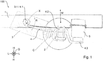
- FIG. 13 shows a side view of a motor vehicle structure 100 according to an embodiment of the invention, wherein Figure 2 shows a schematic plan view of the motor vehicle structure 100.
- the automotive structure 100 is discussed below with common reference to FIGS Figures 1 and 2nd described.
- the motor vehicle structure 100 comprises a chassis (chassis) having two longitudinal members 1, a drive axle 2 which has at least one rotatable drive shaft (not shown), at least one drive unit 3 which has a drive motor (e.g. electric motor) for Having driving the drive axle 2 (drive shaft), and at least one mounting structure 4, designed as a support arm structure, which is rotatably mounted about an axis of rotation X and serves to mount the drive axle 2.
- chassis chassis having two longitudinal members 1, a drive axle 2 which has at least one rotatable drive shaft (not shown), at least one drive unit 3 which has a drive motor (e.g. electric motor) for Having driving the drive axle 2 (drive shaft), and at least one mounting structure 4, designed as a support arm structure, which is rotatably mounted about an axis of rotation X and serves to mount the drive axle 2.
- the drive axle 2 can, for. B. comprise a non-rotatable axle housing and an axle differential connected to the drive unit 3.
- a drive gear can optionally be integrated into the drive unit 3.
- a special feature of the motor vehicle construction 100 is that the drive unit 3 is also mounted rotatably about the essentially same axis of rotation X, so that the axis of rotation X can preferably form an at least almost common axis of rotation for the bearing structure 4 and for the drive unit 3.
- the drive unit 3 is connected to the drive axle 2 in order to be forced into a rotary movement R about the rotation axis X when the drive axle 2 moves in the vertical direction H of the motor vehicle structure 100 due to use.
- the drive unit 3 and the mounting structure 4 are expediently essentially rotatable together about the essentially common axis of rotation X, z.
- the drive unit 3 and the bearing structure 4 can perform a substantially common rotary movement R.
- z. B. be made possible that with movements M of the drive axle 2 in the vertical direction H of the motor vehicle structure 100, a relative movement between the drive unit 3 and the drive axle 2 is at least substantially avoided.
- the bearing structure 4 comprises a (first) rotary bearing 4.1 which defines the axis of rotation X.
- the storage structure 4 can, for. B. even a spring action expediently in the height direction H of the vehicle structure 100 and z. B. have different cross-sectional thicknesses over their longitudinal extent.
- the mounting structure 4 can have a mounting point 4.2 for mounting the drive axle 2.
- the mounting structure 4 can have a stop 4.3 for a spring and / or damper device 5.
- the rotary bearing 4.1 is arranged at one end of the bearing structure 4, the stop 4.3 (spring and / or damper device 5) is arranged at the other end of the bearing structure 4 and the bearing point 4.2 is arranged between the rotary bearing 4.1 and the stop 4.3 (spring and / or damper device 5) is arranged.
- the drive unit 3 is mounted about a (second) rotary bearing 3.1 that defines the axis of rotation X.
- the rotary bearing 4.1 is expediently arranged in the transverse direction Q of the motor vehicle structure 100 outside the two longitudinal members 1, the rotary bearing 3.1 being arranged in the transverse direction Q of the motor vehicle structure 100 within the two longitudinal members 1.
- the drive unit 3 can, for. B. be coupled to the drive axle 2 via a cardan-shaft-free (in particular cardan-joint-free and / or universal joint-free) flange connection structure C, the connection structure C being rotatable in its axial direction for driving the drive axis 2 (drive shaft), and is also rotatable about the axis of rotation X together with the drive unit 3.
- a cardan-shaft-free in particular cardan-joint-free and / or universal joint-free
Landscapes
- Engineering & Computer Science (AREA)
- Mechanical Engineering (AREA)
- Chemical & Material Sciences (AREA)
- Combustion & Propulsion (AREA)
- Transportation (AREA)
- Arrangement Or Mounting Of Propulsion Units For Vehicles (AREA)
Abstract
Description
- Die Erfindung betrifft eine Kraftfahrzeugkonstruktion mit vorzugsweise einem zwei Längsträger umfassenden Chassis, einer Antriebsachse, zumindest einer Antriebseinheit, die ein Antriebsgetriebe und/oder einen Antriebsmotor zum Antreiben der Antriebsachse aufweist, und zumindest einer Lagerungsstruktur zur Lagerung der Antriebsachse.
- Zum allgemeinen Stand der Technik kann zunächst die
DE 10 2013 021 216 A1 genannt werden, aus der ein Kraftfahrzeug bekannt ist mit einer Antriebseinheit, die über eine Kardanwelle mit einer Antriebsachse verbunden ist, um die Antriebsachse anzutreiben. Technologisch bedingt muss die Kardanwelle eine Mindestlänge aufweisen, um einsatzbedingte Relativbewegungen des Kraftfahrzeugs ausgleichen zu können, so dass der Einsatz der Kardanwelle relativ viel Bauraum beansprucht. - Eine Aufgabe der Erfindung ist es, eine Kraftfahrzeugkonstruktion zu schaffen, bei der die Antriebseinheit relativ nahe an die Antriebsachse positioniert werden kann, z. B. um eine möglichst kompakte Anordnung zu ermöglichen.
- Diese Aufgabe kann mit den Merkmalen des Hauptanspruchs gelöst werden. Vorteilhafte Weiterbildungen der Erfindung sind in den Unteransprüchen und der folgenden Beschreibung bevorzugter Ausführungsformen offenbart.
- Die Erfindung betrifft eine Kraftfahrzeugkonstruktion, mit vorzugsweise einem Chassis (z. B. einem Fahrgestell), einer Antriebsachse, die z. B. eine drehbare Antriebswelle und/oder ein Achsgehäuse aufweisen kann, und zumindest einer Antriebseinheit, die ein Antriebsgetriebe und/oder einen Antriebsmotor zum Antreiben der Antriebsachse aufweist. Des Weiteren kann die Kraftfahrzeugkonstruktion zumindest eine Lagerungsstruktur umfassen, die z. B. zur Lagerung der Antriebsachse dient und insbesondere um eine Drehachse drehbar gelagert sein kann.
- Die Kraftfahrzeugkonstruktion zeichnet sich insbesondere dadurch aus, dass die Antriebseinheit zweckmäßig ebenfalls im Wesentlichen um die Drehachse drehbar gelagert sein kann.
- Die Drehachse kann somit vorzugsweise eine im Wesentlichen gemeinsame Drehachse für die Lagerungsstruktur und für die Antriebseinheit bilden.
- Es ist möglich, dass die Antriebseinheit mit der Antriebsachse vorzugsweise im Wesentlichen starr verbunden ist, insbesondere um bei Bewegungen der Antriebsachse in Höhenrichtung der Kraftfahrzeugkonstruktion in eine Drehbewegung um die Drehachse gezwungen zu werden.
- Auch die Lagerungsstruktur kann z. B. im Wesentlichen starr mit der Antriebsachse verbunden sein, insbesondere um bei Bewegungen der Antriebsachse in Höhenrichtung der Kraftfahrzeugkonstruktion in eine Drehbewegung um die Drehachse gezwungen zu werden.
- Dadurch, dass die Antriebseinheit und die Lagerungsstruktur im Wesentlichen um die gleiche Drehachse gedreht werden können, kann z. B. ermöglicht werden, dass bei Bewegungen der Antriebsachse in Höhenrichtung der Kraftfahrzeugkonstruktion die Antriebseinheit und die Lagerungsstruktur eine im Wesentlichen gemeinsame (insbesondere im Wesentlichen gleiche und/oder synchrone) Drehbewegung ausführen. Alternativ oder ergänzend kann z. B. ermöglicht werden, dass bei Bewegungen der Antriebsachse in Höhenrichtung der Kraftfahrzeugkonstruktion eine Relativbewegung zwischen der Antriebseinheit und der Antriebsachse im Wesentlichen vermieden wird, insbesondere weil die Antriebseinheit durch die Antriebsachse in eine Drehbewegung gezwungen werden kann.
- Die Antriebseinheit kann z. B. Gelenkwellen-frei, insbesondere Kardangelenkwellen-frei, und/oder Kreuzgelenk-frei mit der Antriebsachse verbunden sein, um die Antriebsachse anzutreiben, insbesondere deren Antriebswelle.
- Es ist möglich, dass die Lagerungsstruktur um eine erste Drehlagerung drehbar gelagert ist und/oder die Antriebseinheit um eine zweite Drehlagerung drehbar gelagert ist. Die erste Drehlagerung und/oder die zweite Drehlagerung können insbesondere die Drehachse definieren.
- Die Antriebsachse kann z. B. ein nicht drehbares Achsgehäuse umfassen und/oder ein mit der Antriebseinheit verbundenes Achsdifferential.
- Es ist möglich, dass die Antriebseinheit z. B. über eine Verbindungskonstruktion (insbesondere Flansch-Verbindungskonstruktion) an die Antriebsachse gekoppelt ist, wobei die Verbindungskonstruktion in deren Achsrichtung zum Antreiben der Antriebsachse drehbar ist, und/oder zusammen mit der Antriebseinheit um die Drehachse drehbar ist. Die Verbindungskonstruktion kann z. B. einen Antriebseinheit-seitigen Flansch und einen Antriebsachse-seitigen Flansch umfassen.
- Es ist möglich, dass die erste Drehlagerung in Querrichtung der Kraftfahrzeugkonstruktion außerhalb der zwei Längsträger angeordnet ist, und/oder die zweite Drehlagerung in Querrichtung der Kraftfahrzeugkonstruktion innerhalb der zwei Längsträger angeordnet ist.
- Die Lagerungsstruktur kann z. B. im Wesentlichen als Tragarmstruktur ausgebildet sein. Die Tragarmstruktur kann zweckmäßig auf unterschiedlichen Höhen angeordnete Armabschnitte aufweisen.
- Alternativ oder ergänzend kann die Lagerungsstruktur z. B. selbst eine Federwirkung insbesondere in Höhenrichtung der Kraftfahrzeugkonstruktion aufweisen und z. B. als eine Art Blattfeder etc. ausgeführt sein.
- Die Lagerungsstruktur kann z. B. beidseits von der Antriebsachse abstehen.
- Die Lagerungsstruktur kann z. B. an eine Feder-und/oder Dämpfereinrichtung gekoppelt sein, vorzugsweise eine Luftfedereinrichtung, z. B. eine Luftfeder mit zumindest einem Balg. Hierfür kann die Lagerungsstruktur eine entsprechende Haltestelle aufweisen, vorzugsweise am entgegengesetzten Ende der ersten Drehlagerung.
- Die Lagerungsstruktur kann z. B. zwischen der Feder-und/oder Dämpfereinrichtung und der ersten Drehlagerung eine Lagerstelle zur Lagerung der Antriebsachse aufweisen.
- Es ist möglich, dass die Antriebseinheit, optional mit integriertem Antriebsgetriebe, einen Schwerpunkt aufweist und der Schwerpunkt im Wesentlichen mit der Drehachse zusammenfällt.
- Der Antriebsmotor ist vorzugsweise ein Elektromotor, z. B. zum Antreiben des Kraftfahrzeugs.
- Die Lagerungsstruktur kann zweckmäßig über ihre Längserstreckung z. B. unterschiedliche Querschnittsdicken aufweisen. Die unterschiedlichen Querschnittsdicken können sich zweckmäßig zu einer Seite oder zu beiden Seiten der Lagerungsstruktur z. B. verkleinern.
- Zu erwähnen ist, dass das Chassis z. B. Längs- und/oder Querträger aufweisen kann. Die Längs- und/oder Querträger können z. B. als I- oder U-Profile ausgebildet sein. Das Chassis kann aber auch z. B. als Gitterrohrrahmen ausgebildet sein. Auch ein Monocoque-Chassis oder ein herkömmliches leiterrahmenförmiges Chassis sind möglich.
- Zu erwähnen ist außerdem, dass die Drehachse vorzugsweise eine im Wesentlichen horizontale Drehachse sein kann.
- Im Kontext der Erfindung umfasst das Merkmal "Drehachse" insbesondere Ausführungsformen mit gleicher oder zumindest im Wesentlichen gleicher "Drehachse", so dass im Kontext der Erfindung z. B. Toleranz- oder Spiel-bedingte Achsabweichungen als ebenso umfasst gelten.
- Die Antriebsachse dient vorzugsweise zum Antreiben eines oder mehrerer Räder. Bevorzugt ist, dass eine Antriebseinheit zum Antreiben zumindest zweier Räder dient, z. B. einem linken Rad und einem rechten Rad. Es ist aber auch möglich, dass z. B. eine erste Antriebseinheit zum Antreiben eines linken Rads und eine zweite Antriebseinheit zum Antreiben eines rechten Rads dient. Die Antriebswelle kann somit ein- oder zweiteilige Ausführungsformen umfassen.
- Die Erfindung betrifft auch ein Kraftfahrzeug, vorzugsweise ein Nutzfahrzeug, z. B. ein Lastkraftwagen oder Omnibus, mit einer Kraftfahrzeugkonstruktion wie hierin offenbart.
- Die zuvor beschriebenen bevorzugten Ausführungsformen und Merkmale der Erfindung sind miteinander kombinierbar. Andere vorteilhafte Weiterbildungen der Erfindung sind in den Unteransprüchen offenbart oder ergeben sich aus der folgenden Beschreibung bevorzugter Ausführungsformen der Erfindung in Verbindung mit den beigefügten Figuren.
- Figur 1
- zeigt eine Seitenansicht einer Kraftfahrzeugkonstruktion gemäß einer Ausführungsform der Erfindung, und
- Figur
- 2zeigt eine schematische Draufsicht auf die Kraftfahrzeugkonstruktion der
Figur 1 . -
Figur 1 zeigt eine Seitenansicht einer Kraftfahrzeugkonstruktion 100 gemäß einer Ausführungsform der Erfindung, wobeiFigur 2 eine schematische Draufsicht auf die Kraftfahrzeugkonstruktion 100 zeigt. Die Kraftfahrzeugkonstruktion 100 wird nachfolgend unter gemeinsamer Bezugnahme auf dieFiguren 1 und2 beschrieben. - Die Kraftfahrzeugkonstruktion 100 umfasst ein zwei Längsträger 1 aufweisendes Chassis (Fahrgestell), eine Antriebsachse 2, die zumindest eine nicht gezeigte drehbare Antriebswelle aufweist, zumindest eine Antriebseinheit 3, die einen Antriebsmotor (z. B. Elektromotor) zum Antreiben der Antriebsachse 2 (Antriebswelle) aufweist, und zumindest eine als Tragarmstruktur ausgebildete Lagerungsstruktur 4, die um eine Drehachse X drehbar gelagert ist und zur Lagerung der Antriebsachse 2 dient.
- Die Antriebsachse 2 kann z. B. ein nicht drehbares Achsgehäuse umfassen und ein mit der Antriebseinheit 3 verbundenes Achsdifferential. In die Antriebseinheit 3 kann optional ein Antriebsgetriebe integriert sein.
- Eine Besonderheit der Kraftfahrzeugkonstruktion 100 ist, dass die Antriebseinheit 3 ebenfalls um die im wesentlichen gleiche Drehachse X drehbar gelagert ist, so dass vorzugsweise die Drehachse X eine zumindest nahezu gemeinsame Drehachse für die Lagerungsstruktur 4 und für die Antriebseinheit 3 bilden kann.
- Die Antriebseinheit 3 steht mit der Antriebsachse 2 in Verbindung, um bei einsatzbedingten Bewegungen M der Antriebsachse 2 in Höhenrichtung H der Kraftfahrzeugkonstruktion 100 in eine Drehbewegung R um die Drehachse X gezwungen zu werden.
- Dadurch, dass die Antriebseinheit 3 und die Lagerungsstruktur 4 zweckmäßig im Wesentlichen gemeinsam um die im Wesentlichen gemeinsame Drehachse X drehbar sind, kann z. B. ermöglicht werden, dass bei Bewegungen M der Antriebsachse 2 in Höhenrichtung H der Kraftfahrzeugkonstruktion 100 die Antriebseinheit 3 und die Lagerungsstruktur 4 eine im Wesentlichen gemeinsame Drehbewegung R ausführen. Alternativ oder ergänzend kann dadurch z. B. ermöglicht werden, dass bei Bewegungen M der Antriebsachse 2 in Höhenrichtung H der Kraftfahrzeugkonstruktion 100 eine Relativbewegung zwischen der Antriebseinheit 3 und der Antriebsachse 2 zumindest im Wesentlichen vermieden wird.
- Die Lagerungsstruktur 4 umfasst eine die Drehachse X definierende (erste) Drehlagerung 4.1. Die Lagerungsstruktur 4 kann z. B. selbst eine Federwirkung zweckmäßig in Höhenrichtung H der Fahrzeugkonstruktion 100 aufweisen und z. B. über ihre Längserstreckung unterschiedliche Querschnittsdicken aufweisen. Außerdem kann die Lagerungsstruktur 4 eine Lagerstelle 4.2 zur Lagerung der Antriebsachse 2 aufweisen. Des Weiteren kann die Lagerungsstruktur 4 eine Haltestelle 4.3 für eine Feder-und/oder Dämpfereinrichtung 5 aufweisen.
- Bevorzugt ist, wenn die Drehlagerung 4.1 an einem Ende der Lagerungsstruktur 4 angeordnet ist, die Haltestelle 4.3 (Feder-und/oder Dämpfereinrichtung 5) am anderen Ende der Lagerungsstruktur 4 angeordnet ist und die Lagerstelle 4.2 zwischen der Drehlagerung 4.1 und der Haltestelle 4.3 (Feder-und/oder Dämpfereinrichtung 5) angeordnet ist.
- Die Antriebseinheit 3 ist um eine die Drehachse X definierende (zweite) Drehlagerung 3.1 gelagert.
- Die Drehlagerung 4.1 ist zweckmäßig in Querrichtung Q der Kraftfahrzeugkonstruktion 100 außerhalb der zwei Längsträger 1 angeordnet, wobei die Drehlagerung 3.1 in Querrichtung Q der Kraftfahrzeugkonstruktion 100 innerhalb der zwei Längsträger 1 angeordnet ist.
- Die Antriebseinheit 3 kann z. B. über eine Gelenkwellen-freie (insbesondere Kardangelenkwellen-freie, und/oder Kreuzgelenk-freie) Flansch-Verbindungskonstruktion C an die Antriebsachse 2 gekoppelt sein, wobei die Verbindungskonstruktion C in deren Achsrichtung zum Antreiben der Antriebsachse 2 (Antriebswelle) drehbar ist, und zusammen mit der Antriebseinheit 3 ebenfalls um die Drehachse X drehbar ist.
- Die Erfindung ist nicht auf die oben beschriebenen bevorzugten Ausführungsformen beschränkt. Vielmehr ist eine Vielzahl von Varianten und Abwandlungen möglich, die ebenfalls von dem Erfindungsgedanken Gebrauch machen und deshalb in den Schutzbereich fallen. Darüber hinaus beansprucht die Erfindung auch Schutz für den Gegenstand und die Merkmale der Unteransprüche unabhängig von den in Bezug genommenen Merkmalen und Ansprüchen.
-
- 1
- Längsträger
- 2
- Antriebsachse, vorzugsweise mit drehbarer Antriebswelle und/oder Achsgehäuse
- 3
- Antriebseinheit, vorzugsweise mit Antriebsmotor und/oder Antriebsgetriebe
- 3.1
- (zweite) Drehlagerung
- 4
- Lagerungsstruktur
- 4.1
- (erste) Drehlagerung
- 4.2
- Lagerstelle, insbesondere für Antriebsachse
- 4.3
- Haltestelle, insbesondere für Feder- und/oder Dämpfereinrichtung
- 5
- Feder- und/oder Dämpfereinrichtung
- X
- Drehachse
- M
- einsatzbedingte Bewegungen der Antriebsachse
- R
- einsatzbedingte Drehbewegung
- L
- Längsrichtung der Kraftfahrzeugkonstruktion
- H
- Höhenrichtung der Kraftfahrzeugkonstruktion
- Q
- Querrichtung der Kraftfahrzeugkonstruktion
- 100
- Kraftfahrzeugkonstruktion
Claims (16)
- Kraftfahrzeugkonstruktion (100), mit- vorzugsweise einem zwei Längsträger (1) umfassenden Chassis,- einer Antriebsachse (2),- zumindest einer Antriebseinheit (3), die ein Antriebsgetriebe und/oder einen Antriebsmotor zum Antreiben der Antriebsachse (2) aufweist, und- zumindest einer Lagerungsstruktur (4), die um eine Drehachse (X) drehbar gelagert ist und zur Lagerung der Antriebsachse (2) dient,dadurch gekennzeichnet, dass
die Antriebseinheit (3) um die Drehachse (X) drehbar gelagert ist. - Kraftfahrzeugkonstruktion (100) nach Anspruch 1, dadurch gekennzeichnet, dass- die Antriebseinheit (3) mit der Antriebsachse (2) verbunden ist, um bei Bewegungen (M) der Antriebsachse (2) in Höhenrichtung (H) der Kraftfahrzeugkonstruktion (100) in eine Drehbewegung (R) um die Drehachse (X) gezwungen zu werden, und/oder- die Lagerungsstruktur (4) mit der Antriebsachse (2) verbunden ist, um bei Bewegungen (M) der Antriebsachse (2) in Höhenrichtung (H) der Kraftfahrzeugkonstruktion (100) in eine Drehbewegung (R) um die Drehachse (X) gezwungen zu werden.
- Kraftfahrzeugkonstruktion (100) nach Anspruch 1 oder 2, dadurch gekennzeichnet, dass die Antriebseinheit (3) und die Lagerungsstruktur (4) um die Drehachse (X) drehbar sind, um bei Bewegungen (M) der Antriebsachse (2) in Höhenrichtung (H) der Kraftfahrzeugkonstruktion (100) eine im Wesentlichen gemeinsame Drehbewegung (R) auszuführen und/oder um bei Bewegungen (M) der Antriebsachse (2) in Höhenrichtung (H) der Kraftfahrzeugkonstruktion (100) einer Relativbewegung zwischen der Antriebseinheit (3) und der Antriebsachse (2) im Wesentlichen zu vermeiden.
- Kraftfahrzeugkonstruktion (100) nach einem der vorhergehenden Ansprüche, dadurch gekennzeichnet, dass die Antriebseinheit (3) Gelenkwellen-frei, insbesondere Kardangelenkwellen-frei, und/oder Kreuzgelenk-frei mit einer Antriebswelle der Antriebsachse (2) verbunden ist, um die Antriebswelle anzutreiben.
- Kraftfahrzeugkonstruktion (100) nach einem der vorhergehenden Ansprüche, dadurch gekennzeichnet, dass die Lagerungsstruktur (4) um eine erste Drehlagerung (4.1) drehbar gelagert ist und/oder die Antriebseinheit (3) um eine zweite Drehlagerung (3.1) drehbar gelagert ist.
- Kraftfahrzeugkonstruktion (100) nach einem der vorhergehenden Ansprüche, dadurch gekennzeichnet, dass die Antriebsachse (2) ein mit der Antriebseinheit (3) verbundenes Achsdifferential umfasst.
- Kraftfahrzeugkonstruktion (100) nach einem der vorhergehenden Ansprüche, dadurch gekennzeichnet, dass die Antriebseinheit (3) über eine Verbindungskonstruktion (C) an die Antriebsachse (2) gekoppelt ist, wobei die Verbindungskonstruktion (C) in deren Achsrichtung zum Antreiben der Antriebsachse (2) drehbar ist, und zusammen mit der Antriebseinheit (3) um die Drehachse (X) drehbar ist.
- Kraftfahrzeugkonstruktion (100) nach einem der vorhergehenden Ansprüche, dadurch gekennzeichnet, dass- die erste Drehlagerung (4.1) in Querrichtung (Q) der Kraftfahrzeugkonstruktion (100) außerhalb der zwei Längsträger (1) angeordnet ist, und/oder- die zweite Drehlagerung (3.1) in Querrichtung (Q) der Kraftfahrzeugkonstruktion (100) innerhalb der zwei Längsträger (1) angeordnet ist.
- Kraftfahrzeugkonstruktion (100) nach einem der vorhergehenden Ansprüche, dadurch gekennzeichnet, dass die Lagerungsstruktur (4) als Tragarmstruktur ausgebildet ist, selbst eine Federwirkung aufweist und/oder beidseits von der Antriebsachse (2) absteht.
- Kraftfahrzeugkonstruktion (100) nach einem der vorhergehenden Ansprüche, dadurch gekennzeichnet, dass die Lagerungsstruktur (4) an eine Feder-und/oder Dämpfereinrichtung (5) gekoppelt ist, vorzugsweise eine Luftfedereinrichtung.
- Kraftfahrzeugkonstruktion (100) nach einem der vorhergehenden Ansprüche, dadurch gekennzeichnet, dass die Lagerungsstruktur (4) zwischen der Feder-und/oder Dämpfereinrichtung (5) und der ersten Drehlagerung (4.1) eine Lagerstelle (4.2) zur Lagerung der Antriebsachse (2) aufweist.
- Kraftfahrzeugkonstruktion (100) nach einem der vorhergehenden Ansprüche, dadurch gekennzeichnet, dass die Antriebseinheit (3) einen Schwerpunkt aufweist und der Schwerpunkt im Wesentlichen mit der Drehachse (X) zusammenfällt.
- Kraftfahrzeugkonstruktion (100) nach einem der vorhergehenden Ansprüche, dadurch gekennzeichnet, dass der Antriebsmotor einen Elektromotor umfasst.
- Kraftfahrzeugkonstruktion (100) nach einem der vorhergehenden Ansprüche, dadurch gekennzeichnet, dass die Lagerungsstruktur (4) unterschiedliche Querschnittsdicken aufweist.
- Kraftfahrzeugkonstruktion (100) nach einem der vorhergehenden Ansprüche, dadurch gekennzeichnet, dass- die Antriebseinheit (3) mit der Antriebsachse (2) im Wesentlichen starr verbunden ist, und/oder- die Lagerungsstruktur (4) mit der Antriebsachse (2) im Wesentlichen starr verbunden ist.
- Kraftfahrzeug, vorzugsweise Nutzfahrzeug, mit einer Kraftfahrzeugkonstruktion (100) nach einem der vorhergehenden Ansprüche.
Applications Claiming Priority (1)
| Application Number | Priority Date | Filing Date | Title |
|---|---|---|---|
| DE102019103185.0A DE102019103185A1 (de) | 2019-02-08 | 2019-02-08 | Kraftfahrzeugkonstruktion mit Antriebseinheit in Drehachse einer Antriebsachsen-Lagerung |
Publications (2)
| Publication Number | Publication Date |
|---|---|
| EP3693195A1 true EP3693195A1 (de) | 2020-08-12 |
| EP3693195B1 EP3693195B1 (de) | 2023-08-23 |
Family
ID=69630633
Family Applications (1)
| Application Number | Title | Priority Date | Filing Date |
|---|---|---|---|
| EP20154809.6A Active EP3693195B1 (de) | 2019-02-08 | 2020-01-31 | Kraftfahrzeugkonstruktion mit antriebseinheit in drehachse einer antriebsachsen-lagerung |
Country Status (2)
| Country | Link |
|---|---|
| EP (1) | EP3693195B1 (de) |
| DE (1) | DE102019103185A1 (de) |
Cited By (2)
| Publication number | Priority date | Publication date | Assignee | Title |
|---|---|---|---|---|
| US20210162848A1 (en) * | 2018-04-13 | 2021-06-03 | Dana Heavy Vehicle Systems Group, Llc | Support apparatus for an off-axle load |
| EP4748685A1 (de) | 2024-11-26 | 2026-05-27 | DAF Trucks N.V. | Schwerlastfahrzeug |
Citations (10)
| Publication number | Priority date | Publication date | Assignee | Title |
|---|---|---|---|---|
| DE206858C (de) * | 1907-02-05 | 1909-02-11 | ||
| US1178144A (en) * | 1913-10-23 | 1916-04-04 | Roland S Fend | Automobile. |
| DE2605722A1 (de) * | 1976-02-13 | 1977-08-25 | Still Gmbh | Achsfuehrung fuer eine achse eines fahrzeuges |
| EP0004429A2 (de) * | 1978-03-17 | 1979-10-03 | Norgas A/S | Frontradaufhängungsvorrichtung für Elektrofahrzeuge mit Frontantrieb |
| DE102013021216A1 (de) | 2013-12-13 | 2014-07-31 | Daimler Ag | Kraftfahrzeug mit einem Hybridantrieb |
| WO2017172788A1 (en) * | 2016-03-28 | 2017-10-05 | Dana Heavy Vehicle Systems Group, Llc | Suspension rear axle comprising two electric motors |
| DE102017212546A1 (de) * | 2017-07-21 | 2019-01-24 | Ford Global Technologies, Llc | Achsenbaugruppe |
| WO2019161395A1 (en) * | 2018-02-19 | 2019-08-22 | Axletech International Ip Holdings, Llc | Axle assembly for frame rail vehicles |
| WO2019200272A1 (en) * | 2018-04-13 | 2019-10-17 | Dana Heavy Vehicle Systems Group, Llc | Support apparatus for an off-axle load |
| DE102019114828A1 (de) * | 2018-06-05 | 2019-12-05 | Ford Global Technologies, Llc | Achsbaugruppen mit integrierter elektrischer maschine für elektrifizierte fahrzeuge |
Family Cites Families (5)
| Publication number | Priority date | Publication date | Assignee | Title |
|---|---|---|---|---|
| US1540526A (en) * | 1922-03-16 | 1925-06-02 | Joseph A Anglada | Motor vehicle |
| DE875153C (de) * | 1944-02-12 | 1953-04-30 | Daimler Benz Ag | Mit der Achse vereinigter Motor-Getriebe-Differential-Block |
| US3497025A (en) * | 1968-04-25 | 1970-02-24 | Gen Motors Corp | Semi-sprung rear engine driving aggregate |
| EP2199137B1 (de) * | 2008-12-18 | 2012-06-20 | Klingelnberg AG | Radnebenmotor-Anordnung |
| US9914348B2 (en) * | 2014-06-30 | 2018-03-13 | Nissan North America, Inc. | Electric drive motor assembly for a wheel |
-
2019
- 2019-02-08 DE DE102019103185.0A patent/DE102019103185A1/de not_active Withdrawn
-
2020
- 2020-01-31 EP EP20154809.6A patent/EP3693195B1/de active Active
Patent Citations (10)
| Publication number | Priority date | Publication date | Assignee | Title |
|---|---|---|---|---|
| DE206858C (de) * | 1907-02-05 | 1909-02-11 | ||
| US1178144A (en) * | 1913-10-23 | 1916-04-04 | Roland S Fend | Automobile. |
| DE2605722A1 (de) * | 1976-02-13 | 1977-08-25 | Still Gmbh | Achsfuehrung fuer eine achse eines fahrzeuges |
| EP0004429A2 (de) * | 1978-03-17 | 1979-10-03 | Norgas A/S | Frontradaufhängungsvorrichtung für Elektrofahrzeuge mit Frontantrieb |
| DE102013021216A1 (de) | 2013-12-13 | 2014-07-31 | Daimler Ag | Kraftfahrzeug mit einem Hybridantrieb |
| WO2017172788A1 (en) * | 2016-03-28 | 2017-10-05 | Dana Heavy Vehicle Systems Group, Llc | Suspension rear axle comprising two electric motors |
| DE102017212546A1 (de) * | 2017-07-21 | 2019-01-24 | Ford Global Technologies, Llc | Achsenbaugruppe |
| WO2019161395A1 (en) * | 2018-02-19 | 2019-08-22 | Axletech International Ip Holdings, Llc | Axle assembly for frame rail vehicles |
| WO2019200272A1 (en) * | 2018-04-13 | 2019-10-17 | Dana Heavy Vehicle Systems Group, Llc | Support apparatus for an off-axle load |
| DE102019114828A1 (de) * | 2018-06-05 | 2019-12-05 | Ford Global Technologies, Llc | Achsbaugruppen mit integrierter elektrischer maschine für elektrifizierte fahrzeuge |
Cited By (4)
| Publication number | Priority date | Publication date | Assignee | Title |
|---|---|---|---|---|
| US20210162848A1 (en) * | 2018-04-13 | 2021-06-03 | Dana Heavy Vehicle Systems Group, Llc | Support apparatus for an off-axle load |
| US11560047B2 (en) * | 2018-04-13 | 2023-01-24 | Dana Heavy Vehicle Systems Group, Llc | Support apparatus for an off-axle load |
| EP4748685A1 (de) | 2024-11-26 | 2026-05-27 | DAF Trucks N.V. | Schwerlastfahrzeug |
| NL2039169B1 (en) | 2024-11-26 | 2026-06-18 | Daf Trucks Nv | A heavy goods vehicle. |
Also Published As
| Publication number | Publication date |
|---|---|
| DE102019103185A1 (de) | 2020-08-13 |
| EP3693195B1 (de) | 2023-08-23 |
Similar Documents
| Publication | Publication Date | Title |
|---|---|---|
| EP2435287B1 (de) | Wattgestänge-aufhängungseinrichtung mit integrierter federung/dämpfung | |
| DE19957628B4 (de) | Achsaufhängung für Starrachsen von Fahrzeugen | |
| EP1245468B1 (de) | Gelenk zwischen zwei Fahrzeugen oder Fahrzeugteilen (Stichwort: "Drehpendelgelenk") | |
| DE3333706C2 (de) | Aufhängung einer Starrachse für Fahrzeuge | |
| EP2861436A1 (de) | Radaufhängung | |
| DE1530525A1 (de) | Starre Antriebsachse fuer Kraftfahrzeuge | |
| WO2012016610A1 (de) | Achssteller eines kraftfahrzeugs | |
| WO2013185869A1 (de) | Radaufhängung | |
| DE3507426A1 (de) | Aufhaengung fuer eine antriebsachse eines kraftfahrzeuges | |
| DE102017115006A1 (de) | Achsaufhängung | |
| DE102020130723A1 (de) | Kupplungsstruktur einer Radaufhängung | |
| EP3693195B1 (de) | Kraftfahrzeugkonstruktion mit antriebseinheit in drehachse einer antriebsachsen-lagerung | |
| EP3272614A1 (de) | Fahrwerk für ein schienenfahrzeug | |
| WO2022122239A1 (de) | Fahrzeug | |
| DE102012022386A1 (de) | Radaufhängung eines Kraftfahrzeugs | |
| DE102020112535B4 (de) | Radmodul für ein Kraftfahrzeug | |
| DE102017216482A1 (de) | Antriebsstrang einer für ein Arbeitsfahrzeug vorgesehenen angetriebenen Starrachse und knickgelenktes Arbeitsfahrzeug mit einer Starrachse | |
| DE102019126721A1 (de) | Lenksystem mit schubstange | |
| EP4622811A1 (de) | Radaufhängung für ein kraftfahrzeug sowie entsprechendes kraftfahrzeug | |
| EP2158114B1 (de) | Schienenfahrzeug mit einstufiger federung | |
| DE4217261A1 (de) | Antriebsanordnung, insbesondere für Omnibusse | |
| DE102012213864A1 (de) | Elektromechanische Einzelradantriebseinrichtung | |
| DE2605722C3 (de) | Achsführung für eine Starrachse eines Fahrzeuges mit geringer Höchstgeschwindigkeit | |
| DE10062565A1 (de) | Flurförderzeug mit einer federnd aufgehängten Antriebsachse | |
| DE3028007C2 (de) | Knickgelenktes Fahrzeug |
Legal Events
| Date | Code | Title | Description |
|---|---|---|---|
| PUAI | Public reference made under article 153(3) epc to a published international application that has entered the european phase |
Free format text: ORIGINAL CODE: 0009012 |
|
| STAA | Information on the status of an ep patent application or granted ep patent |
Free format text: STATUS: THE APPLICATION HAS BEEN PUBLISHED |
|
| AK | Designated contracting states |
Kind code of ref document: A1 Designated state(s): AL AT BE BG CH CY CZ DE DK EE ES FI FR GB GR HR HU IE IS IT LI LT LU LV MC MK MT NL NO PL PT RO RS SE SI SK SM TR |
|
| AX | Request for extension of the european patent |
Extension state: BA ME |
|
| STAA | Information on the status of an ep patent application or granted ep patent |
Free format text: STATUS: REQUEST FOR EXAMINATION WAS MADE |
|
| 17P | Request for examination filed |
Effective date: 20210211 |
|
| RBV | Designated contracting states (corrected) |
Designated state(s): AL AT BE BG CH CY CZ DE DK EE ES FI FR GB GR HR HU IE IS IT LI LT LU LV MC MK MT NL NO PL PT RO RS SE SI SK SM TR |
|
| STAA | Information on the status of an ep patent application or granted ep patent |
Free format text: STATUS: EXAMINATION IS IN PROGRESS |
|
| 17Q | First examination report despatched |
Effective date: 20220411 |
|
| GRAP | Despatch of communication of intention to grant a patent |
Free format text: ORIGINAL CODE: EPIDOSNIGR1 |
|
| STAA | Information on the status of an ep patent application or granted ep patent |
Free format text: STATUS: GRANT OF PATENT IS INTENDED |
|
| INTG | Intention to grant announced |
Effective date: 20230320 |
|
| GRAS | Grant fee paid |
Free format text: ORIGINAL CODE: EPIDOSNIGR3 |
|
| GRAA | (expected) grant |
Free format text: ORIGINAL CODE: 0009210 |
|
| STAA | Information on the status of an ep patent application or granted ep patent |
Free format text: STATUS: THE PATENT HAS BEEN GRANTED |
|
| AK | Designated contracting states |
Kind code of ref document: B1 Designated state(s): AL AT BE BG CH CY CZ DE DK EE ES FI FR GB GR HR HU IE IS IT LI LT LU LV MC MK MT NL NO PL PT RO RS SE SI SK SM TR |
|
| REG | Reference to a national code |
Ref country code: GB Ref legal event code: FG4D Free format text: NOT ENGLISH |
|
| REG | Reference to a national code |
Ref country code: CH Ref legal event code: EP |
|
| REG | Reference to a national code |
Ref country code: IE Ref legal event code: FG4D Free format text: LANGUAGE OF EP DOCUMENT: GERMAN |
|
| REG | Reference to a national code |
Ref country code: DE Ref legal event code: R096 Ref document number: 502020004797 Country of ref document: DE |
|
| REG | Reference to a national code |
Ref country code: SE Ref legal event code: TRGR |
|
| REG | Reference to a national code |
Ref country code: NL Ref legal event code: FP |
|
| REG | Reference to a national code |
Ref country code: LT Ref legal event code: MG9D |
|
| PG25 | Lapsed in a contracting state [announced via postgrant information from national office to epo] |
Ref country code: GR Free format text: LAPSE BECAUSE OF FAILURE TO SUBMIT A TRANSLATION OF THE DESCRIPTION OR TO PAY THE FEE WITHIN THE PRESCRIBED TIME-LIMIT Effective date: 20231124 |
|
| PG25 | Lapsed in a contracting state [announced via postgrant information from national office to epo] |
Ref country code: IS Free format text: LAPSE BECAUSE OF FAILURE TO SUBMIT A TRANSLATION OF THE DESCRIPTION OR TO PAY THE FEE WITHIN THE PRESCRIBED TIME-LIMIT Effective date: 20231223 |
|
| PG25 | Lapsed in a contracting state [announced via postgrant information from national office to epo] |
Ref country code: RS Free format text: LAPSE BECAUSE OF FAILURE TO SUBMIT A TRANSLATION OF THE DESCRIPTION OR TO PAY THE FEE WITHIN THE PRESCRIBED TIME-LIMIT Effective date: 20230823 Ref country code: PT Free format text: LAPSE BECAUSE OF FAILURE TO SUBMIT A TRANSLATION OF THE DESCRIPTION OR TO PAY THE FEE WITHIN THE PRESCRIBED TIME-LIMIT Effective date: 20231226 Ref country code: NO Free format text: LAPSE BECAUSE OF FAILURE TO SUBMIT A TRANSLATION OF THE DESCRIPTION OR TO PAY THE FEE WITHIN THE PRESCRIBED TIME-LIMIT Effective date: 20231123 Ref country code: LV Free format text: LAPSE BECAUSE OF FAILURE TO SUBMIT A TRANSLATION OF THE DESCRIPTION OR TO PAY THE FEE WITHIN THE PRESCRIBED TIME-LIMIT Effective date: 20230823 Ref country code: LT Free format text: LAPSE BECAUSE OF FAILURE TO SUBMIT A TRANSLATION OF THE DESCRIPTION OR TO PAY THE FEE WITHIN THE PRESCRIBED TIME-LIMIT Effective date: 20230823 Ref country code: IS Free format text: LAPSE BECAUSE OF FAILURE TO SUBMIT A TRANSLATION OF THE DESCRIPTION OR TO PAY THE FEE WITHIN THE PRESCRIBED TIME-LIMIT Effective date: 20231223 Ref country code: HR Free format text: LAPSE BECAUSE OF FAILURE TO SUBMIT A TRANSLATION OF THE DESCRIPTION OR TO PAY THE FEE WITHIN THE PRESCRIBED TIME-LIMIT Effective date: 20230823 Ref country code: GR Free format text: LAPSE BECAUSE OF FAILURE TO SUBMIT A TRANSLATION OF THE DESCRIPTION OR TO PAY THE FEE WITHIN THE PRESCRIBED TIME-LIMIT Effective date: 20231124 Ref country code: FI Free format text: LAPSE BECAUSE OF FAILURE TO SUBMIT A TRANSLATION OF THE DESCRIPTION OR TO PAY THE FEE WITHIN THE PRESCRIBED TIME-LIMIT Effective date: 20230823 |
|
| PG25 | Lapsed in a contracting state [announced via postgrant information from national office to epo] |
Ref country code: PL Free format text: LAPSE BECAUSE OF FAILURE TO SUBMIT A TRANSLATION OF THE DESCRIPTION OR TO PAY THE FEE WITHIN THE PRESCRIBED TIME-LIMIT Effective date: 20230823 |
|
| PG25 | Lapsed in a contracting state [announced via postgrant information from national office to epo] |
Ref country code: ES Free format text: LAPSE BECAUSE OF FAILURE TO SUBMIT A TRANSLATION OF THE DESCRIPTION OR TO PAY THE FEE WITHIN THE PRESCRIBED TIME-LIMIT Effective date: 20230823 |
|
| PG25 | Lapsed in a contracting state [announced via postgrant information from national office to epo] |
Ref country code: SM Free format text: LAPSE BECAUSE OF FAILURE TO SUBMIT A TRANSLATION OF THE DESCRIPTION OR TO PAY THE FEE WITHIN THE PRESCRIBED TIME-LIMIT Effective date: 20230823 Ref country code: RO Free format text: LAPSE BECAUSE OF FAILURE TO SUBMIT A TRANSLATION OF THE DESCRIPTION OR TO PAY THE FEE WITHIN THE PRESCRIBED TIME-LIMIT Effective date: 20230823 Ref country code: ES Free format text: LAPSE BECAUSE OF FAILURE TO SUBMIT A TRANSLATION OF THE DESCRIPTION OR TO PAY THE FEE WITHIN THE PRESCRIBED TIME-LIMIT Effective date: 20230823 Ref country code: EE Free format text: LAPSE BECAUSE OF FAILURE TO SUBMIT A TRANSLATION OF THE DESCRIPTION OR TO PAY THE FEE WITHIN THE PRESCRIBED TIME-LIMIT Effective date: 20230823 Ref country code: DK Free format text: LAPSE BECAUSE OF FAILURE TO SUBMIT A TRANSLATION OF THE DESCRIPTION OR TO PAY THE FEE WITHIN THE PRESCRIBED TIME-LIMIT Effective date: 20230823 Ref country code: CZ Free format text: LAPSE BECAUSE OF FAILURE TO SUBMIT A TRANSLATION OF THE DESCRIPTION OR TO PAY THE FEE WITHIN THE PRESCRIBED TIME-LIMIT Effective date: 20230823 Ref country code: SK Free format text: LAPSE BECAUSE OF FAILURE TO SUBMIT A TRANSLATION OF THE DESCRIPTION OR TO PAY THE FEE WITHIN THE PRESCRIBED TIME-LIMIT Effective date: 20230823 |
|
| REG | Reference to a national code |
Ref country code: DE Ref legal event code: R097 Ref document number: 502020004797 Country of ref document: DE |
|
| PLBE | No opposition filed within time limit |
Free format text: ORIGINAL CODE: 0009261 |
|
| STAA | Information on the status of an ep patent application or granted ep patent |
Free format text: STATUS: NO OPPOSITION FILED WITHIN TIME LIMIT |
|
| 26N | No opposition filed |
Effective date: 20240524 |
|
| PG25 | Lapsed in a contracting state [announced via postgrant information from national office to epo] |
Ref country code: SI Free format text: LAPSE BECAUSE OF FAILURE TO SUBMIT A TRANSLATION OF THE DESCRIPTION OR TO PAY THE FEE WITHIN THE PRESCRIBED TIME-LIMIT Effective date: 20230823 |
|
| PG25 | Lapsed in a contracting state [announced via postgrant information from national office to epo] |
Ref country code: MC Free format text: LAPSE BECAUSE OF FAILURE TO SUBMIT A TRANSLATION OF THE DESCRIPTION OR TO PAY THE FEE WITHIN THE PRESCRIBED TIME-LIMIT Effective date: 20230823 |
|
| PG25 | Lapsed in a contracting state [announced via postgrant information from national office to epo] |
Ref country code: MC Free format text: LAPSE BECAUSE OF FAILURE TO SUBMIT A TRANSLATION OF THE DESCRIPTION OR TO PAY THE FEE WITHIN THE PRESCRIBED TIME-LIMIT Effective date: 20230823 |
|
| REG | Reference to a national code |
Ref country code: CH Ref legal event code: PL |
|
| PG25 | Lapsed in a contracting state [announced via postgrant information from national office to epo] |
Ref country code: LU Free format text: LAPSE BECAUSE OF NON-PAYMENT OF DUE FEES Effective date: 20240131 |
|
| GBPC | Gb: european patent ceased through non-payment of renewal fee |
Effective date: 20240131 |
|
| PG25 | Lapsed in a contracting state [announced via postgrant information from national office to epo] |
Ref country code: LU Free format text: LAPSE BECAUSE OF NON-PAYMENT OF DUE FEES Effective date: 20240131 |
|
| PG25 | Lapsed in a contracting state [announced via postgrant information from national office to epo] |
Ref country code: GB Free format text: LAPSE BECAUSE OF NON-PAYMENT OF DUE FEES Effective date: 20240131 |
|
| PG25 | Lapsed in a contracting state [announced via postgrant information from national office to epo] |
Ref country code: BE Free format text: LAPSE BECAUSE OF NON-PAYMENT OF DUE FEES Effective date: 20240131 |
|
| PG25 | Lapsed in a contracting state [announced via postgrant information from national office to epo] |
Ref country code: CH Free format text: LAPSE BECAUSE OF NON-PAYMENT OF DUE FEES Effective date: 20240131 |
|
| PG25 | Lapsed in a contracting state [announced via postgrant information from national office to epo] |
Ref country code: GB Free format text: LAPSE BECAUSE OF NON-PAYMENT OF DUE FEES Effective date: 20240131 Ref country code: CH Free format text: LAPSE BECAUSE OF NON-PAYMENT OF DUE FEES Effective date: 20240131 Ref country code: BE Free format text: LAPSE BECAUSE OF NON-PAYMENT OF DUE FEES Effective date: 20240131 |
|
| REG | Reference to a national code |
Ref country code: BE Ref legal event code: MM Effective date: 20240131 |
|
| PG25 | Lapsed in a contracting state [announced via postgrant information from national office to epo] |
Ref country code: BG Free format text: LAPSE BECAUSE OF FAILURE TO SUBMIT A TRANSLATION OF THE DESCRIPTION OR TO PAY THE FEE WITHIN THE PRESCRIBED TIME-LIMIT Effective date: 20230823 |
|
| PG25 | Lapsed in a contracting state [announced via postgrant information from national office to epo] |
Ref country code: BG Free format text: LAPSE BECAUSE OF FAILURE TO SUBMIT A TRANSLATION OF THE DESCRIPTION OR TO PAY THE FEE WITHIN THE PRESCRIBED TIME-LIMIT Effective date: 20230823 |
|
| PG25 | Lapsed in a contracting state [announced via postgrant information from national office to epo] |
Ref country code: IE Free format text: LAPSE BECAUSE OF NON-PAYMENT OF DUE FEES Effective date: 20240131 |
|
| PG25 | Lapsed in a contracting state [announced via postgrant information from national office to epo] |
Ref country code: IE Free format text: LAPSE BECAUSE OF NON-PAYMENT OF DUE FEES Effective date: 20240131 |
|
| PGFP | Annual fee paid to national office [announced via postgrant information from national office to epo] |
Ref country code: AT Payment date: 20250417 Year of fee payment: 5 |
|
| PG25 | Lapsed in a contracting state [announced via postgrant information from national office to epo] |
Ref country code: CY Free format text: LAPSE BECAUSE OF FAILURE TO SUBMIT A TRANSLATION OF THE DESCRIPTION OR TO PAY THE FEE WITHIN THE PRESCRIBED TIME-LIMIT; INVALID AB INITIO Effective date: 20200131 |
|
| PG25 | Lapsed in a contracting state [announced via postgrant information from national office to epo] |
Ref country code: HU Free format text: LAPSE BECAUSE OF FAILURE TO SUBMIT A TRANSLATION OF THE DESCRIPTION OR TO PAY THE FEE WITHIN THE PRESCRIBED TIME-LIMIT; INVALID AB INITIO Effective date: 20200131 |
|
| PG25 | Lapsed in a contracting state [announced via postgrant information from national office to epo] |
Ref country code: TR Free format text: LAPSE BECAUSE OF FAILURE TO SUBMIT A TRANSLATION OF THE DESCRIPTION OR TO PAY THE FEE WITHIN THE PRESCRIBED TIME-LIMIT Effective date: 20230823 |
|
| PGFP | Annual fee paid to national office [announced via postgrant information from national office to epo] |
Ref country code: NL Payment date: 20260122 Year of fee payment: 7 |
|
| REG | Reference to a national code |
Ref country code: AT Ref legal event code: MM01 Ref document number: 1602178 Country of ref document: AT Kind code of ref document: T Effective date: 20250131 |
|
| PGFP | Annual fee paid to national office [announced via postgrant information from national office to epo] |
Ref country code: SE Payment date: 20260126 Year of fee payment: 7 |
|
| PGFP | Annual fee paid to national office [announced via postgrant information from national office to epo] |
Ref country code: DE Payment date: 20260127 Year of fee payment: 7 |
|
| PG25 | Lapsed in a contracting state [announced via postgrant information from national office to epo] |
Ref country code: AT Free format text: LAPSE BECAUSE OF NON-PAYMENT OF DUE FEES Effective date: 20250131 |
|
| PGFP | Annual fee paid to national office [announced via postgrant information from national office to epo] |
Ref country code: IT Payment date: 20260123 Year of fee payment: 7 |
|
| PGFP | Annual fee paid to national office [announced via postgrant information from national office to epo] |
Ref country code: FR Payment date: 20260127 Year of fee payment: 7 |