EP3691924B1 - Anzeigevorrichtung und elektrisch angetriebener roller mit entsprechender anzeigevorrichtung - Google Patents
Anzeigevorrichtung und elektrisch angetriebener roller mit entsprechender anzeigevorrichtung Download PDFInfo
- Publication number
- EP3691924B1 EP3691924B1 EP18785871.7A EP18785871A EP3691924B1 EP 3691924 B1 EP3691924 B1 EP 3691924B1 EP 18785871 A EP18785871 A EP 18785871A EP 3691924 B1 EP3691924 B1 EP 3691924B1
- Authority
- EP
- European Patent Office
- Prior art keywords
- display device
- display
- resolution
- cover
- flat screen
- Prior art date
- Legal status (The legal status is an assumption and is not a legal conclusion. Google has not performed a legal analysis and makes no representation as to the accuracy of the status listed.)
- Active
Links
Images


Classifications
-
- B—PERFORMING OPERATIONS; TRANSPORTING
- B62—LAND VEHICLES FOR TRAVELLING OTHERWISE THAN ON RAILS
- B62J—CYCLE SADDLES OR SEATS; AUXILIARY DEVICES OR ACCESSORIES SPECIALLY ADAPTED TO CYCLES AND NOT OTHERWISE PROVIDED FOR, e.g. ARTICLE CARRIERS OR CYCLE PROTECTORS
- B62J50/00—Arrangements specially adapted for use on cycles not provided for in main groups B62J1/00 - B62J45/00
- B62J50/20—Information-providing devices
- B62J50/21—Information-providing devices intended to provide information to rider or passenger
- B62J50/22—Information-providing devices intended to provide information to rider or passenger electronic, e.g. displays
-
- B—PERFORMING OPERATIONS; TRANSPORTING
- B60—VEHICLES IN GENERAL
- B60K—ARRANGEMENT OR MOUNTING OF PROPULSION UNITS OR OF TRANSMISSIONS IN VEHICLES; ARRANGEMENT OR MOUNTING OF PLURAL DIVERSE PRIME-MOVERS IN VEHICLES; AUXILIARY DRIVES FOR VEHICLES; INSTRUMENTATION OR DASHBOARDS FOR VEHICLES; ARRANGEMENTS IN CONNECTION WITH COOLING, AIR INTAKE, GAS EXHAUST OR FUEL SUPPLY OF PROPULSION UNITS IN VEHICLES
- B60K35/00—Instruments specially adapted for vehicles; Arrangement of instruments in or on vehicles
- B60K35/10—Input arrangements, i.e. from user to vehicle, associated with vehicle functions or specially adapted therefor
-
- B—PERFORMING OPERATIONS; TRANSPORTING
- B60—VEHICLES IN GENERAL
- B60K—ARRANGEMENT OR MOUNTING OF PROPULSION UNITS OR OF TRANSMISSIONS IN VEHICLES; ARRANGEMENT OR MOUNTING OF PLURAL DIVERSE PRIME-MOVERS IN VEHICLES; AUXILIARY DRIVES FOR VEHICLES; INSTRUMENTATION OR DASHBOARDS FOR VEHICLES; ARRANGEMENTS IN CONNECTION WITH COOLING, AIR INTAKE, GAS EXHAUST OR FUEL SUPPLY OF PROPULSION UNITS IN VEHICLES
- B60K35/00—Instruments specially adapted for vehicles; Arrangement of instruments in or on vehicles
- B60K35/20—Output arrangements, i.e. from vehicle to user, associated with vehicle functions or specially adapted therefor
- B60K35/21—Output arrangements, i.e. from vehicle to user, associated with vehicle functions or specially adapted therefor using visual output, e.g. blinking lights or matrix displays
- B60K35/213—Virtual instruments
-
- B—PERFORMING OPERATIONS; TRANSPORTING
- B60—VEHICLES IN GENERAL
- B60K—ARRANGEMENT OR MOUNTING OF PROPULSION UNITS OR OF TRANSMISSIONS IN VEHICLES; ARRANGEMENT OR MOUNTING OF PLURAL DIVERSE PRIME-MOVERS IN VEHICLES; AUXILIARY DRIVES FOR VEHICLES; INSTRUMENTATION OR DASHBOARDS FOR VEHICLES; ARRANGEMENTS IN CONNECTION WITH COOLING, AIR INTAKE, GAS EXHAUST OR FUEL SUPPLY OF PROPULSION UNITS IN VEHICLES
- B60K35/00—Instruments specially adapted for vehicles; Arrangement of instruments in or on vehicles
- B60K35/20—Output arrangements, i.e. from vehicle to user, associated with vehicle functions or specially adapted therefor
- B60K35/21—Output arrangements, i.e. from vehicle to user, associated with vehicle functions or specially adapted therefor using visual output, e.g. blinking lights or matrix displays
- B60K35/215—Output arrangements, i.e. from vehicle to user, associated with vehicle functions or specially adapted therefor using visual output, e.g. blinking lights or matrix displays characterised by the combination of multiple visual outputs, e.g. combined instruments with analogue meters and additional displays
-
- B—PERFORMING OPERATIONS; TRANSPORTING
- B60—VEHICLES IN GENERAL
- B60K—ARRANGEMENT OR MOUNTING OF PROPULSION UNITS OR OF TRANSMISSIONS IN VEHICLES; ARRANGEMENT OR MOUNTING OF PLURAL DIVERSE PRIME-MOVERS IN VEHICLES; AUXILIARY DRIVES FOR VEHICLES; INSTRUMENTATION OR DASHBOARDS FOR VEHICLES; ARRANGEMENTS IN CONNECTION WITH COOLING, AIR INTAKE, GAS EXHAUST OR FUEL SUPPLY OF PROPULSION UNITS IN VEHICLES
- B60K35/00—Instruments specially adapted for vehicles; Arrangement of instruments in or on vehicles
- B60K35/20—Output arrangements, i.e. from vehicle to user, associated with vehicle functions or specially adapted therefor
- B60K35/21—Output arrangements, i.e. from vehicle to user, associated with vehicle functions or specially adapted therefor using visual output, e.g. blinking lights or matrix displays
- B60K35/22—Display screens
-
- B—PERFORMING OPERATIONS; TRANSPORTING
- B60—VEHICLES IN GENERAL
- B60K—ARRANGEMENT OR MOUNTING OF PROPULSION UNITS OR OF TRANSMISSIONS IN VEHICLES; ARRANGEMENT OR MOUNTING OF PLURAL DIVERSE PRIME-MOVERS IN VEHICLES; AUXILIARY DRIVES FOR VEHICLES; INSTRUMENTATION OR DASHBOARDS FOR VEHICLES; ARRANGEMENTS IN CONNECTION WITH COOLING, AIR INTAKE, GAS EXHAUST OR FUEL SUPPLY OF PROPULSION UNITS IN VEHICLES
- B60K35/00—Instruments specially adapted for vehicles; Arrangement of instruments in or on vehicles
- B60K35/20—Output arrangements, i.e. from vehicle to user, associated with vehicle functions or specially adapted therefor
- B60K35/28—Output arrangements, i.e. from vehicle to user, associated with vehicle functions or specially adapted therefor characterised by the type of the output information, e.g. video entertainment or vehicle dynamics information; characterised by the purpose of the output information, e.g. for attracting the attention of the driver
-
- B—PERFORMING OPERATIONS; TRANSPORTING
- B60—VEHICLES IN GENERAL
- B60K—ARRANGEMENT OR MOUNTING OF PROPULSION UNITS OR OF TRANSMISSIONS IN VEHICLES; ARRANGEMENT OR MOUNTING OF PLURAL DIVERSE PRIME-MOVERS IN VEHICLES; AUXILIARY DRIVES FOR VEHICLES; INSTRUMENTATION OR DASHBOARDS FOR VEHICLES; ARRANGEMENTS IN CONNECTION WITH COOLING, AIR INTAKE, GAS EXHAUST OR FUEL SUPPLY OF PROPULSION UNITS IN VEHICLES
- B60K35/00—Instruments specially adapted for vehicles; Arrangement of instruments in or on vehicles
- B60K35/20—Output arrangements, i.e. from vehicle to user, associated with vehicle functions or specially adapted therefor
- B60K35/29—Instruments characterised by the way in which information is handled, e.g. showing information on plural displays or prioritising information according to driving conditions
-
- B—PERFORMING OPERATIONS; TRANSPORTING
- B60—VEHICLES IN GENERAL
- B60K—ARRANGEMENT OR MOUNTING OF PROPULSION UNITS OR OF TRANSMISSIONS IN VEHICLES; ARRANGEMENT OR MOUNTING OF PLURAL DIVERSE PRIME-MOVERS IN VEHICLES; AUXILIARY DRIVES FOR VEHICLES; INSTRUMENTATION OR DASHBOARDS FOR VEHICLES; ARRANGEMENTS IN CONNECTION WITH COOLING, AIR INTAKE, GAS EXHAUST OR FUEL SUPPLY OF PROPULSION UNITS IN VEHICLES
- B60K35/00—Instruments specially adapted for vehicles; Arrangement of instruments in or on vehicles
- B60K35/60—Instruments characterised by their location or relative disposition in or on vehicles
-
- B—PERFORMING OPERATIONS; TRANSPORTING
- B62—LAND VEHICLES FOR TRAVELLING OTHERWISE THAN ON RAILS
- B62K—CYCLES; CYCLE FRAMES; CYCLE STEERING DEVICES; RIDER-OPERATED TERMINAL CONTROLS SPECIALLY ADAPTED FOR CYCLES; CYCLE AXLE SUSPENSIONS; CYCLE SIDECARS, FORECARS, OR THE LIKE
- B62K11/00—Motorcycles, engine-assisted cycles or motor scooters with one or two wheels
- B62K11/14—Handlebar constructions, or arrangements of controls thereon, specially adapted thereto
-
- G—PHYSICS
- G01—MEASURING; TESTING
- G01D—MEASURING NOT SPECIALLY ADAPTED FOR A SPECIFIC VARIABLE; ARRANGEMENTS FOR MEASURING TWO OR MORE VARIABLES NOT COVERED IN A SINGLE OTHER SUBCLASS; TARIFF METERING APPARATUS; MEASURING OR TESTING NOT OTHERWISE PROVIDED FOR
- G01D7/00—Indicating measured values
- G01D7/002—Indicating measured values giving both analog and numerical indication
-
- B—PERFORMING OPERATIONS; TRANSPORTING
- B60—VEHICLES IN GENERAL
- B60K—ARRANGEMENT OR MOUNTING OF PROPULSION UNITS OR OF TRANSMISSIONS IN VEHICLES; ARRANGEMENT OR MOUNTING OF PLURAL DIVERSE PRIME-MOVERS IN VEHICLES; AUXILIARY DRIVES FOR VEHICLES; INSTRUMENTATION OR DASHBOARDS FOR VEHICLES; ARRANGEMENTS IN CONNECTION WITH COOLING, AIR INTAKE, GAS EXHAUST OR FUEL SUPPLY OF PROPULSION UNITS IN VEHICLES
- B60K2360/00—Indexing scheme associated with groups B60K35/00 or B60K37/00 relating to details of instruments or dashboards
- B60K2360/1523—Matrix displays
-
- B—PERFORMING OPERATIONS; TRANSPORTING
- B60—VEHICLES IN GENERAL
- B60K—ARRANGEMENT OR MOUNTING OF PROPULSION UNITS OR OF TRANSMISSIONS IN VEHICLES; ARRANGEMENT OR MOUNTING OF PLURAL DIVERSE PRIME-MOVERS IN VEHICLES; AUXILIARY DRIVES FOR VEHICLES; INSTRUMENTATION OR DASHBOARDS FOR VEHICLES; ARRANGEMENTS IN CONNECTION WITH COOLING, AIR INTAKE, GAS EXHAUST OR FUEL SUPPLY OF PROPULSION UNITS IN VEHICLES
- B60K2360/00—Indexing scheme associated with groups B60K35/00 or B60K37/00 relating to details of instruments or dashboards
- B60K2360/18—Information management
- B60K2360/184—Displaying the same information on different displays
-
- B—PERFORMING OPERATIONS; TRANSPORTING
- B60—VEHICLES IN GENERAL
- B60K—ARRANGEMENT OR MOUNTING OF PROPULSION UNITS OR OF TRANSMISSIONS IN VEHICLES; ARRANGEMENT OR MOUNTING OF PLURAL DIVERSE PRIME-MOVERS IN VEHICLES; AUXILIARY DRIVES FOR VEHICLES; INSTRUMENTATION OR DASHBOARDS FOR VEHICLES; ARRANGEMENTS IN CONNECTION WITH COOLING, AIR INTAKE, GAS EXHAUST OR FUEL SUPPLY OF PROPULSION UNITS IN VEHICLES
- B60K2360/00—Indexing scheme associated with groups B60K35/00 or B60K37/00 relating to details of instruments or dashboards
- B60K2360/20—Optical features of instruments
- B60K2360/33—Illumination features
- B60K2360/332—Light emitting diodes
-
- B—PERFORMING OPERATIONS; TRANSPORTING
- B60—VEHICLES IN GENERAL
- B60K—ARRANGEMENT OR MOUNTING OF PROPULSION UNITS OR OF TRANSMISSIONS IN VEHICLES; ARRANGEMENT OR MOUNTING OF PLURAL DIVERSE PRIME-MOVERS IN VEHICLES; AUXILIARY DRIVES FOR VEHICLES; INSTRUMENTATION OR DASHBOARDS FOR VEHICLES; ARRANGEMENTS IN CONNECTION WITH COOLING, AIR INTAKE, GAS EXHAUST OR FUEL SUPPLY OF PROPULSION UNITS IN VEHICLES
- B60K2360/00—Indexing scheme associated with groups B60K35/00 or B60K37/00 relating to details of instruments or dashboards
- B60K2360/20—Optical features of instruments
- B60K2360/33—Illumination features
- B60K2360/338—Light strips
-
- B—PERFORMING OPERATIONS; TRANSPORTING
- B60—VEHICLES IN GENERAL
- B60K—ARRANGEMENT OR MOUNTING OF PROPULSION UNITS OR OF TRANSMISSIONS IN VEHICLES; ARRANGEMENT OR MOUNTING OF PLURAL DIVERSE PRIME-MOVERS IN VEHICLES; AUXILIARY DRIVES FOR VEHICLES; INSTRUMENTATION OR DASHBOARDS FOR VEHICLES; ARRANGEMENTS IN CONNECTION WITH COOLING, AIR INTAKE, GAS EXHAUST OR FUEL SUPPLY OF PROPULSION UNITS IN VEHICLES
- B60K2360/00—Indexing scheme associated with groups B60K35/00 or B60K37/00 relating to details of instruments or dashboards
- B60K2360/77—Instrument locations other than the dashboard
- B60K2360/782—Instrument locations other than the dashboard on the steering wheel
-
- B—PERFORMING OPERATIONS; TRANSPORTING
- B60—VEHICLES IN GENERAL
- B60Y—INDEXING SCHEME RELATING TO ASPECTS CROSS-CUTTING VEHICLE TECHNOLOGY
- B60Y2200/00—Type of vehicle
- B60Y2200/10—Road Vehicles
- B60Y2200/12—Motorcycles, Trikes; Quads; Scooters
- B60Y2200/126—Scooters
-
- B—PERFORMING OPERATIONS; TRANSPORTING
- B62—LAND VEHICLES FOR TRAVELLING OTHERWISE THAN ON RAILS
- B62K—CYCLES; CYCLE FRAMES; CYCLE STEERING DEVICES; RIDER-OPERATED TERMINAL CONTROLS SPECIALLY ADAPTED FOR CYCLES; CYCLE AXLE SUSPENSIONS; CYCLE SIDECARS, FORECARS, OR THE LIKE
- B62K11/00—Motorcycles, engine-assisted cycles or motor scooters with one or two wheels
- B62K11/02—Frames
- B62K11/10—Frames characterised by the engine being over or beside driven rear wheel
-
- B—PERFORMING OPERATIONS; TRANSPORTING
- B62—LAND VEHICLES FOR TRAVELLING OTHERWISE THAN ON RAILS
- B62K—CYCLES; CYCLE FRAMES; CYCLE STEERING DEVICES; RIDER-OPERATED TERMINAL CONTROLS SPECIALLY ADAPTED FOR CYCLES; CYCLE AXLE SUSPENSIONS; CYCLE SIDECARS, FORECARS, OR THE LIKE
- B62K2202/00—Motorised scooters
-
- B—PERFORMING OPERATIONS; TRANSPORTING
- B62—LAND VEHICLES FOR TRAVELLING OTHERWISE THAN ON RAILS
- B62K—CYCLES; CYCLE FRAMES; CYCLE STEERING DEVICES; RIDER-OPERATED TERMINAL CONTROLS SPECIALLY ADAPTED FOR CYCLES; CYCLE AXLE SUSPENSIONS; CYCLE SIDECARS, FORECARS, OR THE LIKE
- B62K2204/00—Adaptations for driving cycles by electric motor
-
- G—PHYSICS
- G01—MEASURING; TESTING
- G01D—MEASURING NOT SPECIALLY ADAPTED FOR A SPECIFIC VARIABLE; ARRANGEMENTS FOR MEASURING TWO OR MORE VARIABLES NOT COVERED IN A SINGLE OTHER SUBCLASS; TARIFF METERING APPARATUS; MEASURING OR TESTING NOT OTHERWISE PROVIDED FOR
- G01D7/00—Indicating measured values
- G01D7/02—Indicating value of two or more variables simultaneously
- G01D7/04—Indicating value of two or more variables simultaneously using a separate indicating element for each variable
Definitions
- the invention relates to a display device and an electrically driven scooter with a corresponding display device.
- Motor scooters equipped with electric drives are, for example, from EP 1 857 314 A2 known.
- Corresponding electric scooters or motorized two-wheelers usually have a body and two wheels, one of the wheels being driven by an electric drive.
- such motor scooters usually have a handlebar assembly, comprising a handlebar and a display device for displaying speed information or the state of charge of a battery.
- an ignition lock is often provided on the handlebar assembly, which serves as an anti-theft device for the scooter.
- the display devices are sometimes equipped with a flat screen, which is protected by a covering layer, for example a glass or plastic layer. Consequently, reflections can occur on the flat screen, which make it difficult to read the flat screen.
- a covering layer for example a glass or plastic layer.
- the readability of the display or flat screen is particularly strongly influenced by external environmental factors such as hail, snow or rain. Furthermore, it is possible that corresponding flat screens fail. Damage to a flat screen, for example a broken pane of glass, can result in the entire vehicle no longer being able to function, since speed information, for example, can no longer be read.
- the safe and legible display of certain information is highly relevant for the driver.
- U.S. 4,646,059 A describes an information display device for a vehicle to display the status of engine and vehicle operating parameters, which do not always have to be displayed during use of the vehicle, at the request of the vehicle operator and automatically upon the occurrence of an out-of-limits condition, via appropriate solid-state display devices to display. For example, a change in vehicle travel speed, a change in remaining fuel quantity or coolant temperature, and a change in engine speed may be displayed.
- DE 40 11 840 A1 describes a display unit for several physical quantities, in particular for driving operation quantities of a motor vehicle, characterized by a display provided for a first physical quantity, the color of which is determined by a second physical quantity.
- EP 2 727 758 A2 teaches a counter display device for a vehicle, comprising: a rotation speed display area that displays a rotation speed of the output shaft of a power source.
- the speed display area is divided into several partial display areas, in which different speed ranges are displayed.
- the sub-display areas have display operating elements which are changed between the minimum value and the maximum value of the respective corresponding sub-speed areas with the increase and decrease of the speed, the sub-display areas being separated from each other on a counter display area.
- DE 10 2010 000 309 A1 teaches an information display system that includes an information display having at least one gauge configured to display information about a vehicle operating condition.
- the information display system also includes a controller that is designed to display information about the vehicle operating state, as well as information that displays a lower limit for a resolution setting and an upper limit for the resolution setting, as well as information that adjusts the resolution setting of the at least one measuring instrument within display the lower limit for the resolution setting and the upper limit for the resolution setting.
- the controller is further configured to transmit information indicative of the vehicle operating condition and the resolution setting such that the at least one gauge displays the vehicle operating condition using the resolution setting.
- a display device which contributes to increasing traffic safety, in particular due to the fact that the information displayed is easy to see.
- the display devices differ in terms of the technology used.
- the second electrical display device can use simple lamps and/or LEDs to visualize information.
- the first display device can be a flat screen, for example based on OLED technology.
- the different technologies have different advantages, so that not only a redundancy is created, but also an optimal representation of the information is always guaranteed in different situations.
- the flat screen can react completely differently to strong sunlight than the light-emitting diodes or LEDs mentioned as examples. In extreme situations, e.g. B. heat, cold, blows, water, react differently.
- the redundant display on different display devices also makes it possible to ensure the safety of the user of the motor scooter in these extreme situations.
- the information displayed can be any information. In one exemplary embodiment, this is a state of charge of a battery of the motor scooter and/or a speed display of the motor scooter.
- the information displayed can be completely different on the first display device are displayed as on the second display device. For example, it is conceivable to display the information on the first display device in the form of numbers, e.g. e.g. 10%, 20%, 30%, 40%.
- the same information can be displayed by means of bars, e.g. B. Loading bar can be shown. For example, six illuminated bars can indicate a full battery charge. If only some of the six available bars are illuminated, the charge level is reduced accordingly.
- the first display device is physically separate from the second display device. Both at least partially display devices are preferably arranged in a cover. If necessary, the physical separation can also be accompanied by an electrical separation of the display devices.
- the second display device can include a large number of light-emitting diodes.
- the number of light-emitting diodes for the second display device is less than 50, in particular less than 20.
- At least some of the light-emitting diodes can be arranged essentially along a straight line or a partial arc of a circle.
- speed displays can also be displayed based on a maximum speed.
- essentially along a straight line and/or a partial circular arc means that the distance between the light-emitting diode and the corresponding straight line or the corresponding partial circular arc is less than or equal to 1 cm, in particular less than or equal to 0.5 cm.
- the first display device comprises an at least substantially rectangular display area.
- the components of the second display devices can be arranged along the rectangular display area, for example on the left-hand side or on the right-hand side.
- a subset of the light-emitting diodes is arranged on the left or the right side of the rectangular display area. At least five light-emitting diodes are preferably provided in each case in order to display a speed or a fill level.
- the display device comprises a cover element.
- the cover element can, for example, be part of the cover already mentioned and can be oriented in such a way that the cover element is arranged on the side facing the user.
- the cover element is preferably transparent at least in sections.
- the first and second display devices can be located on the underside, that is to say on the side of the cover element which is remote from the user.
- At least 80% of the area covering the first display device is transparent.
- the coloring makes it possible to produce different colors.
- the stickers can be used to display symbols, for example to visualize defects.
- the resolution can be more than 10,000 pixels.
- a correspondingly high-resolution display device can be used to display information in a very differentiated manner.
- the display device has a cover, the cover being mounted on a base such that it can pivot, in particular rotate, via a display joint.
- the display device may (in this embodiment) include an actuator operatively connected to the cover and/or the display hinge and configured to pivot the cover from a first position to a second position.
- the display device can also have a control device for controlling the actuator.
- the actuator can be designed as an electric motor, in particular as a brushless DC motor.
- the actuator may be arranged such that a rotary shaft engages the indicator joint in the axial direction such that rotation of the shaft causes the cover to pivot.
- the controller may be configured to, in response to at least one input, control the actuator such that the cover is pivoted from the first position, e.g., a closed position, to the second position, e.g., an open position.
- the display device thus enables the cover to be pivoted between different positions. It is thus possible in a simple manner to adjust the first and/or second display device.
- the cover can be pivoted into a closed position, for example when leaving the vehicle, so that these sensitive components are protected.
- an electrically driven scooter with a display device which includes some or all of the features of the display device described above.
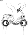
- the 1 shows an electrically driven motor scooter 1 with front and rear wheels 5, 5'.
- An electric motor 2 is integrated into the rim of the rear wheel 5 as an external rotor motor on the rear wheel 5 .
- the electric motor 2 is a Battery 3 fed, which is designed as part of the driver's seat.
- the battery 3 is electrically connected to the motor 2 for this purpose.
- the motor scooter 1 also has a handlebar assembly 6 which includes, among other things, a display device 110 and a throttle grip 9 .
- the 2 shows the link assembly 6 in a rear view.
- the link assembly 6 includes a left rear view mirror 7 and a right rear view mirror 7'.
- the handlebar assembly 6 houses the display device 110, by means of which the operating data or information of the motor scooter 1 are displayed.
- the display device 110 comprises a first display device in the form of a flat screen 120 and a second display device, which can be divided into a number of sub-segments. According to the 3 In the exemplary embodiment shown, these sub-segments are a first sub-segment for displaying the speed (cf. LED speed display 113) and a second sub-segment for displaying the state of charge of the motor scooter (cf. LED charge display 114).
- Other sub-segments deal with the set turn signals or direction indicators (see arrows above), the headlights (see symbols on the lower right side) and other operating states (see the other symbols, eg the battery symbol).
- the currently driven speed and the remaining range of the motor scooter 1 or the state of charge are also displayed on the flat screen 120 .
- light-emitting diodes are provided next to the flat screen 120 under a partially transparent cover element, which display the speed of the motor scooter 1 in a redundant manner. Together with the symbols on the cover element and using non-transparent sections, these light-emitting diodes form the second display device, as shown in an example in 3 is shown.
- the light-emitting diodes can emit differently colored light, which indicates the current driving mode, for example.
- a control device 127 (cf. 4 ) is provided in the handlebar assembly 6, which receives and processes position data from the throttle grip 9. Using the position data, the control unit 127 determines a Operating mode for the electric motor 2. For this purpose, the control device is connected to the battery 3 and the electric motor 2. According to the invention, the operating mode can be displayed on the first and/or second display device.
- the display device 110 further comprises a light sensor 112. This can interact with the first and/or second display device. For example, automatic dimming can take place at night.
- FIGs 4 and 5 show a schematic representation of a further exemplary embodiment of the display device 110.
- the display device 110 can be actuated electrically here.
- the display device 110 is in FIG 4 shown in an open position P2.
- the display device 110 includes a base 111 and a cover 125 in which the flat screen 120 is embedded.
- the flat screen 120 is pivotally connected to the base 111 via a display hinge 121 .
- An electric motor 130 is arranged on the display joint 121 , the drive shaft of which is in operative connection with the display joint 121 .
- the pivoting of the flat screen 120 is therefore carried out via the electric motor 30 .
- a light sensor 112 is arranged on the display device 110 on the flat screen 120 .
- the light sensor 112 is designed as a camera, so that the area in front of the flat screen 120 is recorded.
- the light sensor 112 is preferably designed as a wide-angle camera 112, so that the largest possible area is covered.
- an input device 123 such as a keyboard.
- the input device 123 can be used by a driver to make user inputs. For example, user authentication can be carried out using the input device 123 .
- figure 5 12 shows the indicator 110 in a closed position P1.
- the flat screen 120 the first display device—is pivoted from the open position P2 about the display joint 121 by means of the electric motor 130 been.
- the flat screen 120 is protected from external environmental influences and vandalism.
- a solid surface for example made of aluminum or a plastic, can be provided on the back of the cover 125 .
- a glass pane can be used as a cover element.
- a second indicator in the form of an LED speed indicator 113 is provided.
- the LED speed display 113 can be configured as an LED array.
- the cover member protects the first and second indicators.
Landscapes
- Engineering & Computer Science (AREA)
- Mechanical Engineering (AREA)
- Chemical & Material Sciences (AREA)
- Combustion & Propulsion (AREA)
- Transportation (AREA)
- Physics & Mathematics (AREA)
- General Physics & Mathematics (AREA)
- Devices For Indicating Variable Information By Combining Individual Elements (AREA)
- Indicating Measured Values (AREA)
- Instrument Panels (AREA)
Description
- Die Erfindung betrifft eine Anzeigevorrichtung sowie einen elektrisch angetriebenen Roller mit einer entsprechenden Anzeigevorrichtung.
- Mit elektrischen Antrieben ausgestattete Motorroller sind beispielsweise aus der
EP 1 857 314 A2 bekannt. Entsprechende elektrische Motorroller oder motorisierte Zweiräder haben üblicherweise eine Karosserie und zwei Räder, wobei eines der Räder über einen elektrischen Antrieb angetrieben wird. Ferner haben solche Motorroller üblicherweise eine Lenkerbaugruppe, umfassend einen Lenker sowie eine Anzeigevorrichtung zur Darstellung von Geschwindigkeitsinformationen oder dem Ladezustand einer Batterie. Zusätzlich ist an der Lenkerbaugruppe oftmals ein Zündschloss vorgesehen, welches als Diebstahlsicherung des Motorrollers dient. - Die Anzeigevorrichtungen sind manchmal mit einem Flachbildschirm ausgestattet, welches durch eine Abdeckschicht, beispielsweise eine Glas- oder Kunststoffschicht geschützt wird. Folglich können an dem Flachbildschirm Reflektionen auftreten, die die Lesbarkeit des Flachbildschirms erschweren.
- Die Lesbarkeit des Displays bzw. Flachbildschirms wird besonders stark von äußeren Umweltfaktoren, wie Hagel, Schnee oder Regen, beeinflusst. Weiterhin ist es möglich, dass entsprechende Flachbildschirme ausfallen. Ein Schaden an einem Flachbildschirm, z.B. eine zerbrochene Glasscheibe, kann dazu führen, dass das gesamte Fahrzeug nicht mehr funktionsfähig ist, da z.B. Geschwindigkeitsinformationen nicht mehr abgelesen werden können.
- Allgemein ist die sichere und gut lesbare Darstellung von gewissen Informationen, z.B. Geschwindigkeit, für den Fahrer hoch relevant.
-
US 4 646 059 A beschreibt eine Informationsanzeigevorrichtung für ein Fahrzeug, um den Status von Motor- und Fahrzeugbetriebsparametern, die während der Benutzung des Fahrzeugs nicht immer angezeigt werden müssen, auf Wunsch des Fahrzeugführers und automatisch beim Auftreten eines Zustands, der außerhalb der Grenzwerte liegt, über entsprechende Festkörper-Anzeigevorrichtungen anzuzeigen. Beispielsweise können eine Änderung der Fahrgeschwindigkeit des Fahrzeugs, eine Änderung der verbleibenden Kraftstoffmenge oder der Kühlmitteltemperatur und eine Änderung der Motordrehzahl angezeigt werden. -
DE 40 11 840 A1 beschreibt eine Anzeigeeinheit für mehrere physikalische Größen, insbesondere für Fahrbetriebsgrößen eines Kraftfahrzeugs, gekennzeichnet durch eine für eine erste physikalische Größe vorgesehene Anzeige, deren Farbe durch eine zweite physikalische Größe bestimmt ist. -
EP 0 031 716 A1 lehrt eine Anzeigevorrichtung, die Folgendes umfasst: - eine sichtbare Anzeigefläche; ein Array an Flüssigkristallanzeigesegmenten, das auf der Fläche in Form einer Skala angeordnet wird; eine numerische Anzeige, die eine Vielzahl von Ziffernanzeigen in einer Reihe umfasst, wobei jede Ziffernanzeige eine Mehrsegment-Flüssigkristallanzeige umfasst, die auf der Fläche angeordnet wird und selektiv betrieben werden kann, um Zahlen anzuzeigen; und eine elektronische Schaltung zum Aktivieren des Arrays und der numerischen Anzeige, die Folgendes umfasst: einen Analog-Digital-Wandler zum Empfang eines analogen Eingangssignals zur Umwandlung in eine digitale Form;
- eine erste Decoder-/Treibereinrichtung, die so angeschlossen ist, dass sie das Array als Reaktion auf das Signal in digitaler Form selektiv aktiviert, um ein Segment der Skala in Übereinstimmung mit dem Wert des Eingangssignals zu aktivieren; eine zweite Decoder-/Treibereinrichtung, die so angeschlossen ist, dass sie die numerische Anzeige in Übereinstimmung mit dem Wert des Eingangssignals selektiv aktiviert; der Betrieb der genannten ersten und zweiten Decoder-/Treibermittel steht in Bezug auf die angezeigten Werte in der Weise in Beziehung, dass eine Erhöhung eines Segments der Array-Skala einer Einheitsänderung der Zahl in der zweitniederwertigsten Stelle der numerischen Anzeige entspricht, wobei die niederwertige Stelle eine Interpolation von Werten liefert, die zwischen benachbarten Skalensegmenten liegen.
-
EP 2 727 758 A2 lehrt eine Zähleranzeigevorrichtung für ein Fahrzeug, Folgendes umfassend: einen Drehzahlanzeigebereich, der eine Drehzahl der Abtriebswelle einer Antriebsquelle anzeigt. Der Drehzahlanzeigebereich ist in mehrere Teilanzeigebereiche unterteilt, in denen unterschiedliche Drehzahlbereiche angezeigt werden. Die Teilanzeigebereiche weisen Anzeigebetätigungselemente auf, die zwischen dem Minimalwert und dem Maximalwert der jeweiligen entsprechenden Teil-Drehzahlbereiche mit der Zunahme und Abnahme der Drehzahl verändert werden, wobei die Teilanzeigebereiche auf einer Zähleranzeigefläche voneinander getrennt sind. -
DE 10 2010 000 309 A1 lehrt ein Informationsanzeigesystem, das eine Informationsanzeige mit mindestens einem Messinstrument umfasst, das dazu ausgebildet ist, Informationen über einen Fahrzeugbetriebszustand anzuzeigen. Das Informationsanzeigesystem umfasst ferner einen Controller, der dazu ausgebildet ist, Informationen über den anzuzeigenden Fahrzeugbetriebszustand, sowie Informationen, die eine untere Grenze für eine Auflösungseinstellung und eine obere Grenze für die Auflösungseinstellung anzeigen, sowie Informationen, die eine Anpassung der Auflösungseinstellung des mindestens einen Messinstruments innerhalb der unteren Grenze für die Auflösungseinstellung und der oberen Grenze für die Auflösungseinstellung anzeigen zu empfangen. Der Controller ist ferner dazu ausgebildet, Informationen, die den Fahrzeugbetriebszustand und die Auflösungseinstellung anzeigen zu übertragen, so dass das mindestens eine Messinstrument den Fahrzeugbetriebszustand unter Verwendung der Auflösungseinstellung anzeigt. - Ausgehend von diesem Stand der Technik ist es Aufgabe der vorliegenden Erfindung, die vorstehend beschriebenen Nachteile zu beheben. Insbesondere soll eine Anzeigevorrichtung bereitgestellt werden, die dazu beiträgt, die Verkehrssicherheit, insbesondere auf Grund einer guten Wahrnehmbarkeit der angezeigten Informationen, zu erhöhen.
- Die Aufgabe wird durch eine Anzeigevorrichtung gemäß dem Anspruch 1 sowie durch einen elektrisch angetriebenen Roller gemäß dem Anspruch 14 gelöst. Insbesondere wird die Aufgabe durch eine Anzeigevorrichtung für einen elektrisch angetriebenen Roller gelöst, wobei die Anzeigevorrichtung umfasst:
- eine erste Anzeigeeinrichtung, nämlich einen Flachbildschirm, mit einer ersten Auflösung;
- eine zweite elektrische oder elektronische Anzeigeeinrichtung mit einer zweiten Auflösung, wobei vorzugsweise die zweite Auflösung deutlich geringer ist als die erste Auflösung,
- Ein Gedanke der vorliegenden Erfindung besteht also darin, wichtige Informationen, beispielsweise Messwerte und/oder Stellgrößen auf zwei sich unterscheidenden Anzeigeeinrichtungen darzustellen. In einer Ausführungsform unterscheiden sich die Anzeigeeinrichtungen hinsichtlich der verwendeten Technologie. So kann beispielsweise die zweite elektrische Anzeigeeinrichtung einfache Lampen und/oder LEDs verwenden, um Informationen zu visualisieren. Die erste Anzeigeeinrichtung kann ein Flachbildschirm, beispielsweise basierend auf OLED-Technologie sein. Die unterschiedlichen Technologien haben unterschiedliche Vorteile, so dass nicht nur eine Redundanz geschaffen wird, sondern auch in sich unterscheidenden Situationen stets eine optimale Darstellung der Information gewährleistet ist. So kann der Flachbildschirm beispielsweise völlig anders auf starke Sonneneinstrahlung reagieren als die exemplarisch genannten Leuchtdioden bzw. LEDs. Die erste und die zweite Anzeigeeinrichtung können in Extremsituationen, z. B. Hitze, Kälte, Schläge, Wasser, unterschiedlich reagieren. Das redundante Anzeigen auf unterschiedlichen Anzeigeeinrichtungen ermöglicht es auch, in diesen Extremsituationen die Sicherheit des Benutzers des Motorrollers zu gewährleisten.
- Die angezeigte Information kann jede beliebige Information sein. In einem Ausführungsbeispiel handelt es sich hierbei um einen Ladezustand einer Batterie des Motorrollers und/oder eine Geschwindigkeitsanzeige des Motorrollers. Die angezeigte Information kann auf der ersten Anzeigeeinrichtung völlig anders dargestellt werden, wie auf der zweiten Anzeigeeinrichtung. Beispielsweise ist es denkbar, die Informationen auf der ersten Anzeigeeinrichtung aufgrund der hohen Auflösung in Form von Zahlen, z. B. 10 %, 20 %, 30 %, 40 % darzustellen. Bei der zweiten Anzeigeeinrichtung kann die gleiche Information mittels Balken, z. B. Ladebalken dargestellt sein. So können beispielsweise sechs beleuchtete Balken eine vollständige Ladung der Batterie anzeigen. Soweit nur einige der sechs verfügbaren Balken beleuchtet sind, ist der Ladezustand entsprechend reduziert.
- In einer Ausführungsform ist die erste Anzeigeeinrichtung physisch getrennt von der zweiten Anzeigeeinrichtung angeordnet. Vorzugsweise sind beide zumindest teilweise Anzeigeeinrichtungen in einer Abdeckung angeordnet. Gegebenenfalls kann die physische Trennung auch mit einer elektrischen Trennung der Anzeigeeinrichtungen einhergehen.
- Wie bereits erläutert, kann die zweite Anzeigeeinrichtung eine Vielzahl von Leuchtdioden umfassen. In einer Ausführungsform ist die Anzahl der Leuchtdioden für die zweite Anzeigeeinrichtung kleiner als 50, insbesondere kleiner als 20.
- Zumindest einige der Leuchtdioden können im Wesentlichen entlang einer Geraden oder einem Teilkreisbogen angeordnet sein. Mittels einer entsprechenden Anordnung ist es möglich, Füllzustände bzw. Ladezustände besonders gut zu visualisieren. Entsprechend können auch Geschwindigkeitsanzeigen ausgehend von einer Maximalgeschwindigkeit angezeigt werden. Erfindungsgemäß bedeutet im Wesentlichen entlang einer Geraden und/oder eines Teilkreisbogens, dass der Abstand zwischen der Leuchtdiode und der entsprechenden Geraden oder dem entsprechenden Teilkreisbogen kleiner oder gleich als 1 cm, insbesondere kleiner oder gleich als 0,5 cm ist.
- In einer Ausführungsform umfasst die erste Anzeigeeinrichtung eine zumindest im Wesentlichen rechteckige Anzeigefläche. Die Bauelemente der zweiten Anzeigeeinrichtungen können in dieser Ausführungsform entlang, beispielsweise linksseitig oder rechtsseitig der rechteckigen Anzeigefläche angeordnet sein. In einer bevorzugten Ausführungsform ist eine Teilmenge der Leuchtdioden auf der linken oder der rechten Seite der rechteckigen Anzeigefläche angeordnet. Vorzugsweise sind jeweils mindestens fünf Leuchtdioden vorgesehen, um eine Geschwindigkeit oder einen Füllzustand anzuzeigen.
- In einer Ausführungsform umfasst die Anzeigevorrichtung ein Abdeckungselement. Das Abdeckungselement kann beispielsweise Teil der bereits genannten Abdeckung und derart ausgerichtet sein, dass das Abdeckungselement auf der dem Benutzer zugewandten Seite angeordnet ist. Das Abdeckungselement ist vorzugsweise zumindest abschnittsweise transparent. An der Unterseite, also der dem Benutzer abgewandten Seite des Abdeckungselements, können sich die erste und die zweite Anzeigeeinrichtung befinden.
- In einer Ausführungsform sind zumindest 80 % des Bereichs, der die erste Anzeigeeinrichtung überdeckt, transparent. Oberhalb von Bauelementen, beispielsweise Leuchtdioden, der zweiten Anzeigeeinrichtung, können Einfärbungen oder Beklebungen oder Gravuren vorhanden sein. Die Einfärbungen ermöglichen es, unterschiedliche Farben herzustellen. Mittels der Beklebung können Symbole, beispielsweise zur Visualisierung von Defekten dargestellt werden.
- In einer Ausführungsform kann die Auflösung mehr als 10.000 Bildpunkte betragen. Eine entsprechend hochauflösende Anzeigeeinrichtung kann verwendet werden, um Informationen sehr differenziert anzuzeigen.
- In einer Ausführungsform weist die Anzeigevorrichtung eine Abdeckung auf, wobei die Abdeckung über ein Anzeigegelenk verschwenkbar, insbesondere drehbeweglich, an einer Basis gelagert ist. Die Anzeigevorrichtung kann (in dieser Ausführungsform) einen Aktuator aufweisen, der in Wirkverbindung mit der Abdeckung und/oder dem Anzeigegelenk steht und dazu ausgebildet ist, die Abdeckung von einer ersten Stellung in eine zweite Stellung zu verschwenken. Die Anzeigevorrichtung kann darüber hinaus eine Steuereinrichtung zum Ansteuern des Aktuators aufweisen.
- Der Aktuator kann als Elektromotor, insbesondere als ein bürstenloser Gleichstrommotor, ausgebildet sein. Der Aktuator kann derart angeordnet sein, dass eine Drehwelle in axialer Richtung derart in das Anzeigegelenk eingreift, dass eine Drehung der Welle ein Verschwenken der Abdeckung bewirkt.
- Die Steuereinrichtung kann dazu ausgebildet sein, in Reaktion auf mindestens eine Eingabe, den Aktuator derart anzusteuern, dass die Abdeckung von der ersten Stellung, z.B. einer geschlossenen Stellung, in die zweite Stellung, z.B. einer geöffneten Stellung, verschwenkt wird.
- In einer Ausführungsform ermöglicht die Anzeigevorrichtung also das Verschwenken der Abdeckung zwischen verschiedenen Stellungen. Es ist somit auf einfache Weise möglich, die erste und/oder zweite Anzeigeeinrichtung zu verstellen. Zum Schutz der ersten und/oder zweiten Anzeigeeinrichtung kann die Abdeckung zum Beispiel beim Verlassen des Fahrzeugs in eine geschlossene Stellung verschwenkt werden, sodass diese empfindlichen Komponenten geschützt sind.
- Die eingangs genannte Aufgabe wird weiterhin durch einen elektrisch angetriebenen Roller mit einer Anzeigevorrichtung gelöst, die einige oder alle Merkmale der vorab beschriebenen Anzeigevorrichtung umfasst.
- Im Folgenden wird die Erfindung anhand von Figuren näher erläutert. Dabei zeigen:
- Fig. 1
- einen elektrisch angetriebenen Motorroller in einer Seitenansicht;
- Fig. 2
- eine Lenkerbaugruppe in einer Rückansicht;
- Fig. 3
- eine Anzeigevorrichtung mit einer ersten und einer zweiten Anzeigevorrichtung
- Fig. 4
- eine Anzeigevorrichtung in geöffneter Stellung;
- Fig. 5
- die Anzeigevorrichtung der
Fig. 3 in geschlossener Stellung; - Im Folgenden werden für gleiche oder gleichwirkende Teile dieselben Bezugsziffern verwendet.
- Die
Fig. 1 zeigt einen elektrisch angetriebenen Motorroller 1 mit Vorder- und Hinterrad 5, 5'. An dem Hinterrad 5 ist ein Elektromotor 2 als Außenläufermotor in die Felge des Hinterrades 5 integriert. Der Elektromotor 2 wird über eine Batterie 3 gespeist, die als Teil des Fahrersitzes ausgebildet ist. Hierzu ist die Batterie 3 mit dem Motor 2 elektrisch verbunden. Der Motorroller 1 verfügt ferner über eine Lenkerbaugruppe 6, die u.a. eine Anzeigevorrichtung 110 und einen Gasdrehgriff 9 umfasst. - Die
Fig. 2 zeigt die Lenkerbaugruppe 6 in einer Rückansicht. Die Lenkerbaugruppe 6 umfasst einen linken Rückspiegel 7 sowie einen rechten Rückspiegel 7'. Die Lenkerbaugruppe 6 beherbergt die Anzeigevorrichtung 110, mittels derer die Betriebsdaten bzw. Informationen des Motorrollers 1 angezeigt werden. Die Anzeigevorrichtung 110 umfasst eine erste Anzeigeeinrichtung in Form eines Flachbildschirms 120 sowie eine zweite Anzeigeeinrichtung, die sich in mehrere Teilsegmente untergliedern lässt. Gemäß dem inFig. 3 gezeigten Ausführungsbeispiel handelt es sich bei diesen Teilsegmenten, um ein erstes Teilsegment zur Darstellung der Geschwindigkeit (vgl. LED-Geschwindigkeitsanzeige 113) sowie um ein zweites Teilsegment zur Darstellung des Ladezustands des Motorrollers (vgl. LED-Ladeanzeige 114). Weitere Teilsegmente beschäftigen sich mit den gesetzten Blinkern bzw. Fahrtrichtungsanzeigern (vgl. Pfeile oben), den Scheinwerfern (vgl. Symbole auf der unteren rechten Seite) und weiteren Betriebszuständen (vgl. die weiteren Symbole, z.B. das Batteriesymbol). - Auch auf dem Flachbildschirm 120 wird erfindungsgemäß die aktuell gefahrene Geschwindigkeit sowie die verbleibende Reichweite des Motorrollers 1 bzw. der Ladezustand angezeigt. Zur Erhöhung der Sicherheit sind neben dem Flachbildschirm 120, unter einem teilweise transparenten Abdeckungselement Leuchtdioden vorgesehen, die in redundanter Weise die Geschwindigkeit des Motorrollers 1 anzeigen. Diese Leuchtdioden bilden die zusammen mit den Symbolen auf dem Abdeckungselement und unter Nutzung von nichttransparenten Abschnitten die zweite Anzeigeeinrichtung, wie diese exemplarisch in
Fig. 3 dargestellt ist. - Die Leuchtdioden können unterschiedlich eingefärbtes Licht emittieren, das beispielsweise den momentanen Fahrmodus angibt.
- Ferner ist eine Steuereinrichtung 127 (vgl.
Fig. 4 ) in der Lenkerbaugruppe 6 vorgesehen, die Positionsdaten von dem Gasdrehgriff 9 empfängt und verarbeitet. Unter Verwendung der Positionsdaten bestimmt die Steuereinheit 127 einen Betriebsmodus für den Elektromotor 2. Hierzu ist die Steuereinrichtung mit der Batterie 3 und dem Elektromotor 2 verbunden. Der Betriebsmodus kann erfindungsgemäß auf der ersten und/oder zweiten Anzeigeeinrichtung dargestellt werden. - In einem Ausführungsbeispiel umfasst die Anzeigevorrichtung 110 weiterhin einen Lichtsensor 112. Dieses kann mit der ersten und/oder zweiten Anzeigeeinrichtung interagieren. Beispielsweise kann eine automatische Dimmung in der Nacht erfolgen.
-
Fig. 4 und 5 zeigen eine schematische Darstellung eines weiteren Ausführungsbeispiels der Anzeigevorrichtung 110. Die Anzeigevorrichtung 110 ist hier elektrisch betätigbar. Die Anzeigevorrichtung 110 ist in derFig. 4 in einer geöffneten Stellung P2 dargestellt. Die Anzeigevorrichtung 110 umfasst eine Basis 111 sowie eine Abdeckung 125, in die der Flachbildschirm 120 eingelassen ist. Der Flachbildschirm 120 ist über ein Anzeigegelenk 121 mit der Basis 111 verschwenkbar verbunden. - An dem Anzeigegelenk 121 ist ein Elektromotor 130 angeordnet, dessen Antriebswelle mit dem Anzeigegelenk 121 in Wirkverbindung steht. Das Verschwenken des Flachbildschirms 120 wird also über den Elektromotor 30 ausgeführt.
- An der Anzeigevorrichtung 110 ist an dem Flachbildschirm 120 ein Lichtsensor 112 angeordnet. Der Lichtsensor 112 ist in der vorliegenden Ausführungsform als Kamera ausgebildet, so dass der Bereich vor dem Flachbildschirm 120 erfasst wird. Vorzugsweise ist der Lichtsensor 112 als Weitwinkelkamera 112 ausgebildet, so dass ein möglichst großer Bereich erfasst wird.
- An der Basis 111 ist ferner eine Eingabeeinrichtung 123, wie z.B. eine Tastatur, vorgesehen. Die Eingabeeinrichtung 123 kann von einem Fahrer dazu verwendet werden, Benutzereingaben vorzunehmen. Beispielsweise kann eine Benutzerauthentifikation mittels der Eingabeeinrichtung 123 ausgeführt werden.
-
Fig. 5 zeigt die Anzeigevorrichtung 110 in einer geschlossenen Stellung P1. Der Flachbildschirm 120 - die erste Anzeigeeinrichtung - ist hierzu von der geöffneten Stellung P2 um das Anzeigegelenk 121 mittels des Elektromotors 130 verschwenkt worden. In der geschlossenen Stellung P1 ist der Flachbildschirm 120 vor äußeren Umwelteinflüssen und Vandalismus geschützt. Hierzu kann an der Rückseite der Abdeckung 125 eine feste Oberfläche, z.B. aus Aluminium oder einem Kunststoff vorgesehen sein. Auf der Vorderseite der Abdeckung 125 kann sich eine Glasscheibe als Abdeckungselement. Auch bei dem Ausführungsbeispiel gemäßFig. 4 und 5 ist eine zweite Anzeigeeinrichtung in Form einer LED-Geschwindigkeitsanzeige 113 vorgesehen. Die LED-Geschwindigkeitsanzeige 113 kann als LED-Array ausgebildet sein. Das Abdeckungselement schützt die erste und die zweite Anzeigeeinrichtung. - Abschließend wird darauf hingewiesen, dass die einzelnen Komponenten oder Ausführungsbeispiele jeweils einzeln und in jeder beliebigen Kombination als erfindungswesentlich beansprucht werden. Abwandlungen hiervon sind dem Fachmann geläufig und sind von der Patentanmeldung umfasst.
-
- 1
- Motorroller
- 2
- Motor
- 3
- Batterie
- 5, 5'
- Vorder- Hinterrad
- 6
- Lenkerbaugruppe
- 7, 7'
- Linker und rechter Rückspiegel
- 8
- Blinkerhebel
- 9
- Gasdrehgriff
- 10
- Griffteil
- 12
- Drehteil
- 110
- Anzeigevorrichtung
- 111
- Basis
- 112
- Lichtsensor
- 113
- LED-Geschwindigkeitsanzeige
- 114
- LED-Ladeanzeige
- 115
- Abdeckung
- 120
- Flachbildschirm
- 121
- Anzeigegelenk
- 122
- Spiegelebene
- 123
- Eingabeeinrichtung
- 130
- Elektromotor
- 140
- Steuereinrichtung
Claims (10)
- Anzeigevorrichtung (110) für einen elektrisch angetriebenen Motorroller (1), Folgendes aufweisend:- eine erste Anzeigeeinrichtung, nämlich einen Flachbildschirm (120), mit einer ersten Auflösung;- eine zweite elektrische oder elektronische Anzeigeeinrichtung mit einer zweiten Auflösung, wobei vorzugsweise die zweite Auflösung deutlich geringer ist als die erste Auflösung,wobeidie Anzeigevorrichtung (110) dazu ausgebildet ist, eine Information, die auf einem Messwert (1) und/oder einer Stellgröße basiert, gleichzeitig auf der ersten Anzeigeeinrichtung und der zweiten Anzeigeeinrichtung anzuzeigen,dadurch gekennzeichnet, dassdie erste Auflösung um mindestens 70% höher als die zweite Auflösung ist und wobei die erste Anzeigeeinrichtung ein LCD-Flachbildschirm, ein Plasma-Flachbildschirm oder ein OLED-Flachbildschirm mit einer Auflösung von mehr als 1000 Bildpunkten umfasst.
- Anzeigevorrichtung (110) nach Anspruch 1,
dadurch gekennzeichnet, dass
die erste Anzeigeeinrichtung physisch getrennt von der zweiten Anzeigeeinrichtung, vorzugsweise in einer Abdeckung (125), angeordnet ist. - Anzeigevorrichtung (110) nach einem der vorhergehenden Ansprüche,
dadurch gekennzeichnet, dass
die zweite Anzeigeeinrichtung eine Vielzahl von Leuchtdioden umfasst, wobei die Anzahl der Leuchtdioden kleiner als 50, insbesondere kleiner als 20 ist. - Anzeigevorrichtung (110) nach einem der vorhergehenden Ansprüche, insbesondere nach Anspruch 3,
dadurch gekennzeichnet, dass
zumindest einige der Leuchtdioden im Wesentlichen entlang einer Geraden oder einem Teilkreisbogen angeordnet sind. - Anzeigevorrichtung (110) nach einem der vorhergehenden Ansprüche,
dadurch gekennzeichnet, dass
die erste Anzeigeeinrichtung eine zumindest im Wesentlichen rechteckige Anzeigefläche umfasst, wobei zumindest einige der Bauelemente, insbesondere der Leuchtdioden, der zweiten Anzeigeeinrichtung entlang der Seitenränder der Anzeigefläche angeordnet sind. - Anzeigevorrichtung (110) nach einem der vorhergehenden Ansprüche,
gekennzeichnet durch:
ein zumindest abschnittsweise transparentes Abdeckungselement mit einer Oberseite und einer Unterseite, wobei die erste und zweite Anzeigeeinrichtung jeweils an der Unterseite der Abdeckung angeordnet sind. - Anzeigevorrichtung (110) nach einem der vorhergehenden Ansprüche, insbesondere nach Anspruch 6,
dadurch gekennzeichnet, dass
zumindest einige Abschnitte des transparenten Abdeckungselements oberhalb von Bauelementen, insbesondere Leuchtdioden, der zweiten Anzeigeeinrichtung beklebt und/oder eingefärbt sind. - Anzeigevorrichtung (110) nach einem der vorhergehenden Ansprüche,
dadurch gekennzeichnet, dass
die erste Anzeigeeinrichtung mehr als 10000 Bildpunkte umfasst. - Anzeigevorrichtung (110) nach einem der vorhergehenden Ansprüche,
gekennzeichnet durch:- eine/die Abdeckung (125) zur Aufnahme der ersten und/oder zweiten Anzeigeeinrichtung, und- eine Basis (111), wobei die Abdeckung über ein Anzeigegelenk (121) an der Basis derart angebracht ist, dass die Abdeckung von einer ersten Stellung (P1) in eine zweite Stellung (P2) verschwenkbar ist. - Elektrisch angetriebener Roller mit einer Anzeigevorrichtung (110) nach einem der vorhergehenden Ansprüche.
Applications Claiming Priority (2)
| Application Number | Priority Date | Filing Date | Title |
|---|---|---|---|
| DE102017122850.0A DE102017122850B4 (de) | 2017-10-02 | 2017-10-02 | Anzeigevorrichtung und elektrisch angetriebener Roller mit entsprechender Anzeigevorrichtung |
| PCT/EP2018/076464 WO2019068580A2 (de) | 2017-10-02 | 2018-09-28 | Anzeigevorrichtung und elektrisch angetriebener roller mit entsprechender anzeigevorrichtung |
Publications (3)
| Publication Number | Publication Date |
|---|---|
| EP3691924A2 EP3691924A2 (de) | 2020-08-12 |
| EP3691924C0 EP3691924C0 (de) | 2023-08-02 |
| EP3691924B1 true EP3691924B1 (de) | 2023-08-02 |
Family
ID=63840801
Family Applications (1)
| Application Number | Title | Priority Date | Filing Date |
|---|---|---|---|
| EP18785871.7A Active EP3691924B1 (de) | 2017-10-02 | 2018-09-28 | Anzeigevorrichtung und elektrisch angetriebener roller mit entsprechender anzeigevorrichtung |
Country Status (5)
| Country | Link |
|---|---|
| EP (1) | EP3691924B1 (de) |
| JP (1) | JP2020536278A (de) |
| DE (1) | DE102017122850B4 (de) |
| ES (1) | ES2960456T3 (de) |
| WO (1) | WO2019068580A2 (de) |
Families Citing this family (9)
| Publication number | Priority date | Publication date | Assignee | Title |
|---|---|---|---|---|
| US12409756B2 (en) | 2017-04-05 | 2025-09-09 | H55 Sa | Aircraft monitoring system and method for electric or hybrid aircrafts |
| US11065979B1 (en) | 2017-04-05 | 2021-07-20 | H55 Sa | Aircraft monitoring system and method for electric or hybrid aircrafts |
| US10479223B2 (en) | 2018-01-25 | 2019-11-19 | H55 Sa | Construction and operation of electric or hybrid aircraft |
| IL303714A (en) * | 2019-12-13 | 2023-10-01 | Neutron Holdings Inc Dba Lime | Controller for light electric vehicle |
| CN112158286A (zh) * | 2020-10-22 | 2021-01-01 | 象山侧风电子技术有限公司 | 一种易拆装的防污防尘自行车码表座 |
| CN116745160A (zh) * | 2020-11-18 | 2023-09-12 | Tvs电机股份有限公司 | 车辆的多面仪表板组件 |
| CN116761736A (zh) * | 2020-12-01 | 2023-09-15 | Tvs电机股份有限公司 | 仪表板控制系统 |
| CN113135254B (zh) * | 2021-04-17 | 2022-07-22 | 深圳市威特利电源有限公司 | 一种电动骑行交通工具的追踪充电系统及方法 |
| CA3237131A1 (en) | 2021-11-05 | 2023-05-11 | Stephane Pierre-Jean Boirin | Information display system and method for electric or hybrid aircrafts |
Citations (4)
| Publication number | Priority date | Publication date | Assignee | Title |
|---|---|---|---|---|
| EP0031716A1 (de) * | 1979-12-28 | 1981-07-08 | Federal Products Corporation | Messgerät mit einer analogen und digitalen Anzeige |
| US4646059A (en) * | 1981-02-26 | 1987-02-24 | Mazda Motor Corporation | Solid-state information display apparatus for automobile vehicle |
| DE4011840A1 (de) * | 1989-04-19 | 1990-10-25 | Volkswagen Ag | Anzeigeeinheit fuer mehrere physikalische groessen, insbesondere in einem kraftfahrzeug |
| EP2727758A2 (de) * | 2012-11-06 | 2014-05-07 | Kawasaki Jukogyo Kabushiki Kaisha | Meteranzeigevorrichtung für ein Fahrzeug |
Family Cites Families (12)
| Publication number | Priority date | Publication date | Assignee | Title |
|---|---|---|---|---|
| DE19700515A1 (de) * | 1997-01-09 | 1998-07-16 | Aguti Prod Entw & Design Gmbh | Informationseinrichtung für ein Kraftfahrzeug |
| US6069788A (en) * | 1997-06-28 | 2000-05-30 | Shimano, Inc. | Foldable bicycle computer |
| JP4251734B2 (ja) * | 1999-09-06 | 2009-04-08 | 本田技研工業株式会社 | ナビゲーションシステム搭載型自動二輪車 |
| DE10042495A1 (de) * | 2000-08-30 | 2002-03-14 | Volkswagen Ag | Vorrichtung zur Positionierung eines Bildbetrachtungsmittels |
| DE10061190A1 (de) * | 2000-12-11 | 2002-06-13 | Heinz Leiber | Kraftfahrzeug |
| DE10214200C1 (de) * | 2002-03-28 | 2003-11-20 | Siemens Ag | Kombiinstrument und Anordnung mit einem Kombiinstrument |
| JP2004017801A (ja) * | 2002-06-17 | 2004-01-22 | Kawasaki Heavy Ind Ltd | 自動二輪車用表示装置 |
| US7135964B2 (en) * | 2002-11-04 | 2006-11-14 | Spx Corporation | Data link connector (DLC) driven display |
| DE102007002080A1 (de) | 2006-05-19 | 2007-11-22 | Lutz Baur | Fahrzeug mit einem elektrisch angetriebenen Fahrmodus |
| US20100207757A1 (en) * | 2009-02-16 | 2010-08-19 | Ford Global Technologies, Llc | System and method for adjusting the resolution of an information display for a vehicle |
| DE102015105331B4 (de) * | 2015-04-08 | 2023-02-16 | Ujet S.A. | Elektrischer Motorroller |
| WO2016203526A1 (ja) * | 2015-06-15 | 2016-12-22 | 三菱電機株式会社 | 映像表示機器 |
-
2017
- 2017-10-02 DE DE102017122850.0A patent/DE102017122850B4/de active Active
-
2018
- 2018-09-28 EP EP18785871.7A patent/EP3691924B1/de active Active
- 2018-09-28 WO PCT/EP2018/076464 patent/WO2019068580A2/de not_active Ceased
- 2018-09-28 JP JP2020518689A patent/JP2020536278A/ja active Pending
- 2018-09-28 ES ES18785871T patent/ES2960456T3/es active Active
Patent Citations (4)
| Publication number | Priority date | Publication date | Assignee | Title |
|---|---|---|---|---|
| EP0031716A1 (de) * | 1979-12-28 | 1981-07-08 | Federal Products Corporation | Messgerät mit einer analogen und digitalen Anzeige |
| US4646059A (en) * | 1981-02-26 | 1987-02-24 | Mazda Motor Corporation | Solid-state information display apparatus for automobile vehicle |
| DE4011840A1 (de) * | 1989-04-19 | 1990-10-25 | Volkswagen Ag | Anzeigeeinheit fuer mehrere physikalische groessen, insbesondere in einem kraftfahrzeug |
| EP2727758A2 (de) * | 2012-11-06 | 2014-05-07 | Kawasaki Jukogyo Kabushiki Kaisha | Meteranzeigevorrichtung für ein Fahrzeug |
Also Published As
| Publication number | Publication date |
|---|---|
| EP3691924A2 (de) | 2020-08-12 |
| EP3691924C0 (de) | 2023-08-02 |
| JP2020536278A (ja) | 2020-12-10 |
| DE102017122850A1 (de) | 2019-04-04 |
| WO2019068580A2 (de) | 2019-04-11 |
| ES2960456T3 (es) | 2024-03-04 |
| DE102017122850B4 (de) | 2023-05-17 |
| WO2019068580A3 (de) | 2019-05-31 |
Similar Documents
| Publication | Publication Date | Title |
|---|---|---|
| EP3691924B1 (de) | Anzeigevorrichtung und elektrisch angetriebener roller mit entsprechender anzeigevorrichtung | |
| EP1633620B1 (de) | Anzeigeeinheit und verfahren zur anzeige eines lenkradeinschlags eines fahrzeugs | |
| DE102005003920B4 (de) | Anzeigeeinheit | |
| DE10026136B4 (de) | Transparente elektrolumineszierende Anzeige mit mechanischem Messer | |
| DE102008041024A1 (de) | Digitales verbundenes Anzeige-Kombiinstrument für ein Fahrzeug | |
| EP3571082A1 (de) | Kombiinstrument mit verformbarer anzeige | |
| DE102020113398A1 (de) | Kraftfahrzeug mit zumindest einer Funktionsoberflächenschicht | |
| DE102005034771A1 (de) | Abdeckung einer Fahrzeugoberfläche | |
| DE102004038916A1 (de) | Anzeigeeinrichtung für ein Kraftfahrzeug | |
| WO2016202427A1 (de) | Beleuchtungseinrichtung mit einem anzeigeelement | |
| DE102006025023A1 (de) | Elektronisch konfigurierbares Kennzeichen | |
| DE102020133840A1 (de) | Fahrzeug mit einer E-Paper-Anzeigeeinrichtung | |
| WO2022069472A1 (de) | Fahrzeug mit einer designbeleuchtung | |
| WO2012163670A1 (de) | Fahrzeugcomputer zur projektions eines betriebsparameters auf die fahrbahn | |
| EP2930137B1 (de) | Flurförderzeug | |
| DE102013020782A1 (de) | Fahrzeug mit Leuchtanzeigeinstrument | |
| DE102016209914B4 (de) | Kraftfahrzeug mit einer Scheibenvorrichtung | |
| DE102009054079B4 (de) | Verfahren zum Anzeigen der Größe des Energieverbrauchs in einem Kraftfahrzeug | |
| DE102008052420B4 (de) | Anzeigevorrichtung für ein Fahrzeug | |
| DE102014214767B4 (de) | Anzeigeeinrichtung für ein Kraftfahrzeug, insbesondere Head-up-Display und Verfahren zur Steuerung einer Anzeigeeinrichtung | |
| DE102015204377B4 (de) | Anzeigevorrichtung für ein Fahrzeug | |
| EP0991301A1 (de) | Scheibenheizung für Kraftfahrzeuge | |
| DE102004018293A1 (de) | Fahrtregler-Anzeiger | |
| DE3622458A1 (de) | Die ausbildung einer armaturentafel in einem kraftfahrzeug | |
| EP3756926B1 (de) | Kombiinstrument eines kraftfahrzeugs |
Legal Events
| Date | Code | Title | Description |
|---|---|---|---|
| STAA | Information on the status of an ep patent application or granted ep patent |
Free format text: STATUS: UNKNOWN |
|
| STAA | Information on the status of an ep patent application or granted ep patent |
Free format text: STATUS: THE INTERNATIONAL PUBLICATION HAS BEEN MADE |
|
| PUAI | Public reference made under article 153(3) epc to a published international application that has entered the european phase |
Free format text: ORIGINAL CODE: 0009012 |
|
| STAA | Information on the status of an ep patent application or granted ep patent |
Free format text: STATUS: REQUEST FOR EXAMINATION WAS MADE |
|
| 17P | Request for examination filed |
Effective date: 20200504 |
|
| AK | Designated contracting states |
Kind code of ref document: A2 Designated state(s): AL AT BE BG CH CY CZ DE DK EE ES FI FR GB GR HR HU IE IS IT LI LT LU LV MC MK MT NL NO PL PT RO RS SE SI SK SM TR |
|
| AX | Request for extension of the european patent |
Extension state: BA ME |
|
| DAV | Request for validation of the european patent (deleted) | ||
| DAX | Request for extension of the european patent (deleted) | ||
| STAA | Information on the status of an ep patent application or granted ep patent |
Free format text: STATUS: EXAMINATION IS IN PROGRESS |
|
| 17Q | First examination report despatched |
Effective date: 20220317 |
|
| GRAP | Despatch of communication of intention to grant a patent |
Free format text: ORIGINAL CODE: EPIDOSNIGR1 |
|
| STAA | Information on the status of an ep patent application or granted ep patent |
Free format text: STATUS: GRANT OF PATENT IS INTENDED |
|
| INTG | Intention to grant announced |
Effective date: 20230221 |
|
| GRAS | Grant fee paid |
Free format text: ORIGINAL CODE: EPIDOSNIGR3 |
|
| GRAA | (expected) grant |
Free format text: ORIGINAL CODE: 0009210 |
|
| STAA | Information on the status of an ep patent application or granted ep patent |
Free format text: STATUS: THE PATENT HAS BEEN GRANTED |
|
| AK | Designated contracting states |
Kind code of ref document: B1 Designated state(s): AL AT BE BG CH CY CZ DE DK EE ES FI FR GB GR HR HU IE IS IT LI LT LU LV MC MK MT NL NO PL PT RO RS SE SI SK SM TR |
|
| REG | Reference to a national code |
Ref country code: GB Ref legal event code: FG4D Free format text: NOT ENGLISH |
|
| REG | Reference to a national code |
Ref country code: CH Ref legal event code: EP |
|
| REG | Reference to a national code |
Ref country code: DE Ref legal event code: R096 Ref document number: 502018012884 Country of ref document: DE |
|
| REG | Reference to a national code |
Ref country code: IE Ref legal event code: FG4D Free format text: LANGUAGE OF EP DOCUMENT: GERMAN |
|
| U01 | Request for unitary effect filed |
Effective date: 20230817 |
|
| U07 | Unitary effect registered |
Designated state(s): AT BE BG DE DK EE FI FR IT LT LU LV MT NL PT SE SI Effective date: 20230824 |
|
| U20 | Renewal fee for the european patent with unitary effect paid |
Year of fee payment: 6 Effective date: 20230929 |
|
| PG25 | Lapsed in a contracting state [announced via postgrant information from national office to epo] |
Ref country code: GR Free format text: LAPSE BECAUSE OF FAILURE TO SUBMIT A TRANSLATION OF THE DESCRIPTION OR TO PAY THE FEE WITHIN THE PRESCRIBED TIME-LIMIT Effective date: 20231103 |
|
| PG25 | Lapsed in a contracting state [announced via postgrant information from national office to epo] |
Ref country code: IS Free format text: LAPSE BECAUSE OF FAILURE TO SUBMIT A TRANSLATION OF THE DESCRIPTION OR TO PAY THE FEE WITHIN THE PRESCRIBED TIME-LIMIT Effective date: 20231202 |
|
| PG25 | Lapsed in a contracting state [announced via postgrant information from national office to epo] |
Ref country code: RS Free format text: LAPSE BECAUSE OF FAILURE TO SUBMIT A TRANSLATION OF THE DESCRIPTION OR TO PAY THE FEE WITHIN THE PRESCRIBED TIME-LIMIT Effective date: 20230802 Ref country code: NO Free format text: LAPSE BECAUSE OF FAILURE TO SUBMIT A TRANSLATION OF THE DESCRIPTION OR TO PAY THE FEE WITHIN THE PRESCRIBED TIME-LIMIT Effective date: 20231102 Ref country code: IS Free format text: LAPSE BECAUSE OF FAILURE TO SUBMIT A TRANSLATION OF THE DESCRIPTION OR TO PAY THE FEE WITHIN THE PRESCRIBED TIME-LIMIT Effective date: 20231202 Ref country code: HR Free format text: LAPSE BECAUSE OF FAILURE TO SUBMIT A TRANSLATION OF THE DESCRIPTION OR TO PAY THE FEE WITHIN THE PRESCRIBED TIME-LIMIT Effective date: 20230802 Ref country code: GR Free format text: LAPSE BECAUSE OF FAILURE TO SUBMIT A TRANSLATION OF THE DESCRIPTION OR TO PAY THE FEE WITHIN THE PRESCRIBED TIME-LIMIT Effective date: 20231103 |
|
| PG25 | Lapsed in a contracting state [announced via postgrant information from national office to epo] |
Ref country code: PL Free format text: LAPSE BECAUSE OF FAILURE TO SUBMIT A TRANSLATION OF THE DESCRIPTION OR TO PAY THE FEE WITHIN THE PRESCRIBED TIME-LIMIT Effective date: 20230802 |
|
| REG | Reference to a national code |
Ref country code: ES Ref legal event code: FG2A Ref document number: 2960456 Country of ref document: ES Kind code of ref document: T3 Effective date: 20240304 |
|
| PG25 | Lapsed in a contracting state [announced via postgrant information from national office to epo] |
Ref country code: SM Free format text: LAPSE BECAUSE OF FAILURE TO SUBMIT A TRANSLATION OF THE DESCRIPTION OR TO PAY THE FEE WITHIN THE PRESCRIBED TIME-LIMIT Effective date: 20230802 Ref country code: RO Free format text: LAPSE BECAUSE OF FAILURE TO SUBMIT A TRANSLATION OF THE DESCRIPTION OR TO PAY THE FEE WITHIN THE PRESCRIBED TIME-LIMIT Effective date: 20230802 Ref country code: CZ Free format text: LAPSE BECAUSE OF FAILURE TO SUBMIT A TRANSLATION OF THE DESCRIPTION OR TO PAY THE FEE WITHIN THE PRESCRIBED TIME-LIMIT Effective date: 20230802 Ref country code: SK Free format text: LAPSE BECAUSE OF FAILURE TO SUBMIT A TRANSLATION OF THE DESCRIPTION OR TO PAY THE FEE WITHIN THE PRESCRIBED TIME-LIMIT Effective date: 20230802 |
|
| REG | Reference to a national code |
Ref country code: CH Ref legal event code: PL |
|
| REG | Reference to a national code |
Ref country code: DE Ref legal event code: R097 Ref document number: 502018012884 Country of ref document: DE |
|
| PG25 | Lapsed in a contracting state [announced via postgrant information from national office to epo] |
Ref country code: MC Free format text: LAPSE BECAUSE OF FAILURE TO SUBMIT A TRANSLATION OF THE DESCRIPTION OR TO PAY THE FEE WITHIN THE PRESCRIBED TIME-LIMIT Effective date: 20230802 |
|
| PLBE | No opposition filed within time limit |
Free format text: ORIGINAL CODE: 0009261 |
|
| STAA | Information on the status of an ep patent application or granted ep patent |
Free format text: STATUS: NO OPPOSITION FILED WITHIN TIME LIMIT |
|
| REG | Reference to a national code |
Ref country code: IE Ref legal event code: MM4A |
|
| PG25 | Lapsed in a contracting state [announced via postgrant information from national office to epo] |
Ref country code: IE Free format text: LAPSE BECAUSE OF NON-PAYMENT OF DUE FEES Effective date: 20230928 |
|
| 26N | No opposition filed |
Effective date: 20240503 |
|
| PG25 | Lapsed in a contracting state [announced via postgrant information from national office to epo] |
Ref country code: CH Free format text: LAPSE BECAUSE OF NON-PAYMENT OF DUE FEES Effective date: 20230930 |
|
| GBPC | Gb: european patent ceased through non-payment of renewal fee |
Effective date: 20231102 |
|
| PG25 | Lapsed in a contracting state [announced via postgrant information from national office to epo] |
Ref country code: IE Free format text: LAPSE BECAUSE OF NON-PAYMENT OF DUE FEES Effective date: 20230928 Ref country code: CH Free format text: LAPSE BECAUSE OF NON-PAYMENT OF DUE FEES Effective date: 20230930 |
|
| PG25 | Lapsed in a contracting state [announced via postgrant information from national office to epo] |
Ref country code: GB Free format text: LAPSE BECAUSE OF NON-PAYMENT OF DUE FEES Effective date: 20231102 |
|
| PG25 | Lapsed in a contracting state [announced via postgrant information from national office to epo] |
Ref country code: GB Free format text: LAPSE BECAUSE OF NON-PAYMENT OF DUE FEES Effective date: 20231102 |
|
| U20 | Renewal fee for the european patent with unitary effect paid |
Year of fee payment: 7 Effective date: 20240930 |
|
| PG25 | Lapsed in a contracting state [announced via postgrant information from national office to epo] |
Ref country code: CY Free format text: LAPSE BECAUSE OF FAILURE TO SUBMIT A TRANSLATION OF THE DESCRIPTION OR TO PAY THE FEE WITHIN THE PRESCRIBED TIME-LIMIT; INVALID AB INITIO Effective date: 20180928 |
|
| PG25 | Lapsed in a contracting state [announced via postgrant information from national office to epo] |
Ref country code: HU Free format text: LAPSE BECAUSE OF FAILURE TO SUBMIT A TRANSLATION OF THE DESCRIPTION OR TO PAY THE FEE WITHIN THE PRESCRIBED TIME-LIMIT; INVALID AB INITIO Effective date: 20180928 |
|
| U20 | Renewal fee for the european patent with unitary effect paid |
Year of fee payment: 8 Effective date: 20250930 |
|
| PG25 | Lapsed in a contracting state [announced via postgrant information from national office to epo] |
Ref country code: TR Free format text: LAPSE BECAUSE OF FAILURE TO SUBMIT A TRANSLATION OF THE DESCRIPTION OR TO PAY THE FEE WITHIN THE PRESCRIBED TIME-LIMIT Effective date: 20230802 |
|
| PGFP | Annual fee paid to national office [announced via postgrant information from national office to epo] |
Ref country code: ES Payment date: 20251015 Year of fee payment: 8 |