EP3691799B1 - Siebvorrichtung - Google Patents
Siebvorrichtung Download PDFInfo
- Publication number
- EP3691799B1 EP3691799B1 EP18799763.0A EP18799763A EP3691799B1 EP 3691799 B1 EP3691799 B1 EP 3691799B1 EP 18799763 A EP18799763 A EP 18799763A EP 3691799 B1 EP3691799 B1 EP 3691799B1
- Authority
- EP
- European Patent Office
- Prior art keywords
- screen
- housing
- screening
- sieve
- granules
- Prior art date
- Legal status (The legal status is an assumption and is not a legal conclusion. Google has not performed a legal analysis and makes no representation as to the accuracy of the status listed.)
- Active
Links
Images


Classifications
-
- B—PERFORMING OPERATIONS; TRANSPORTING
- B07—SEPARATING SOLIDS FROM SOLIDS; SORTING
- B07B—SEPARATING SOLIDS FROM SOLIDS BY SIEVING, SCREENING, SIFTING OR BY USING GAS CURRENTS; SEPARATING BY OTHER DRY METHODS APPLICABLE TO BULK MATERIAL, e.g. LOOSE ARTICLES FIT TO BE HANDLED LIKE BULK MATERIAL
- B07B1/00—Sieving, screening, sifting, or sorting solid materials using networks, gratings, grids, or the like
- B07B1/06—Cone or disc shaped screens
-
- B—PERFORMING OPERATIONS; TRANSPORTING
- B02—CRUSHING, PULVERISING, OR DISINTEGRATING; PREPARATORY TREATMENT OF GRAIN FOR MILLING
- B02C—CRUSHING, PULVERISING, OR DISINTEGRATING IN GENERAL; MILLING GRAIN
- B02C23/00—Auxiliary methods or auxiliary devices or accessories specially adapted for crushing or disintegrating not provided for in preceding groups or not specially adapted to apparatus covered by a single preceding group
- B02C23/18—Adding fluid, other than for crushing or disintegrating by fluid energy
- B02C23/24—Passing gas through crushing or disintegrating zone
- B02C23/30—Passing gas through crushing or disintegrating zone the applied gas acting to effect material separation
-
- B—PERFORMING OPERATIONS; TRANSPORTING
- B07—SEPARATING SOLIDS FROM SOLIDS; SORTING
- B07B—SEPARATING SOLIDS FROM SOLIDS BY SIEVING, SCREENING, SIFTING OR BY USING GAS CURRENTS; SEPARATING BY OTHER DRY METHODS APPLICABLE TO BULK MATERIAL, e.g. LOOSE ARTICLES FIT TO BE HANDLED LIKE BULK MATERIAL
- B07B1/00—Sieving, screening, sifting, or sorting solid materials using networks, gratings, grids, or the like
- B07B1/18—Drum screens
- B07B1/20—Stationary drums with moving interior agitators
-
- B—PERFORMING OPERATIONS; TRANSPORTING
- B07—SEPARATING SOLIDS FROM SOLIDS; SORTING
- B07B—SEPARATING SOLIDS FROM SOLIDS BY SIEVING, SCREENING, SIFTING OR BY USING GAS CURRENTS; SEPARATING BY OTHER DRY METHODS APPLICABLE TO BULK MATERIAL, e.g. LOOSE ARTICLES FIT TO BE HANDLED LIKE BULK MATERIAL
- B07B1/00—Sieving, screening, sifting, or sorting solid materials using networks, gratings, grids, or the like
- B07B1/46—Constructional details of screens in general; Cleaning or heating of screens
- B07B1/4609—Constructional details of screens in general; Cleaning or heating of screens constructional details of screening surfaces or meshes
- B07B1/469—Perforated sheet-like material
-
- B—PERFORMING OPERATIONS; TRANSPORTING
- B07—SEPARATING SOLIDS FROM SOLIDS; SORTING
- B07B—SEPARATING SOLIDS FROM SOLIDS BY SIEVING, SCREENING, SIFTING OR BY USING GAS CURRENTS; SEPARATING BY OTHER DRY METHODS APPLICABLE TO BULK MATERIAL, e.g. LOOSE ARTICLES FIT TO BE HANDLED LIKE BULK MATERIAL
- B07B11/00—Arrangement of accessories in apparatus for separating solids from solids using gas currents
- B07B11/06—Feeding or discharging arrangements
-
- B—PERFORMING OPERATIONS; TRANSPORTING
- B07—SEPARATING SOLIDS FROM SOLIDS; SORTING
- B07B—SEPARATING SOLIDS FROM SOLIDS BY SIEVING, SCREENING, SIFTING OR BY USING GAS CURRENTS; SEPARATING BY OTHER DRY METHODS APPLICABLE TO BULK MATERIAL, e.g. LOOSE ARTICLES FIT TO BE HANDLED LIKE BULK MATERIAL
- B07B4/00—Separating solids from solids by subjecting their mixture to gas currents
- B07B4/08—Separating solids from solids by subjecting their mixture to gas currents while the mixtures are supported by sieves, screens, or like mechanical elements
Definitions
- the invention relates to a screening device for screening granules, in particular moist and/or dry granules, comprising a screen housing having a bottom, a lid and a side wall, an inlet opening for the granules arranged on the screen housing, an outlet opening for the screened granules arranged on the screen housing, a screen arranged in the screen housing and an inlet opening for transfer air arranged on the screen housing.
- Screening devices for granules particularly for screening processes downstream of a wet granulation process or a drying process in a fluidization apparatus, have long been state of the art. These known screens are filled through an inlet opening for the granules located on the cover of the screen and emptied after the screening process through an outlet opening located in the base of the screen after a suction shoe. The granules are transported from the inlet opening to the outlet opening, for example, via gravity feeding or pneumatic conveying.
- EP 0 159 050 A1 discloses a device for separating grain into fractions of different densities.
- the device comprises two superimposed, air-permeable, and oscillating fluidized bed tables.
- the upper fluidised bed table is fed with the grain via an inlet, opposite which is an outlet for the light fraction.
- the lower fluidised bed table has an outlet for the heavy grain fraction, opposite which is an outlet for the heaviest grain fraction at the other end.
- the upper fluidised bed table be divided into at least two consecutive areas with different perforation sizes, from the inlet towards the outlet for the light grain fraction.
- the perforation of the upper fluidised bed table is designed in such a way that the aforementioned grain fractions can only fall through in the area(s) following the first area.
- a tray is arranged which extends across its width, with an outlet for a medium-heavy grain fraction adjoining the end of the tray opposite the inlet.
- the impurity removal box for feeding raw materials, wherein the impurity removal box comprises a housing, a screening mechanism, a drive mechanism, and an air blower; a feed opening is formed in the upper end of the housing; the housing is further provided with a discharge opening, an air inlet, and an air outlet; the air inlet and the air outlet are located below the feed port; the air outlet is smaller than the air inlet and the air outlet; the screening mechanism is arranged within the housing and is provided with a screening shaft and multiple layers of coarse screening screens; the screening shaft is rotatably mounted on the housing; the multiple layers of coarse screening screens are mounted on the screening shaft from top to bottom; the meshes of all coarse screening screens are sequentially enlarged from top to bottom; and the drive mechanism serves to rotate the screen shaft.
- the impurity removal box On the one hand, dust and light impurities mixed in the feed raw materials are removed by the airflow generated by the air blower.
- multiple layers of rotary coarse screens are arranged to screen and separate the feed raw materials and solid impurities, so that the impurity removal box is convenient to use and has a good foreign matter separation effect.
- a screening device for crushing and subsequently screening material is shown, wherein the screening device has a conical sieve in a conical housing, the fine screened material is transported away through the outlet opening and non-crushed material is discharged via the outlet opening at the sieve bottom.
- WO 91/08059 A1 shows a screening device with an inlet for the material to be screened and an outlet for the screened material arranged in a side wall.
- the screen A grinding body is arranged which is driven by a motor.
- US 2004/056128 A1 discloses an impact mill comprising a cylindrical housing in which both a polygonal screen and a circular screen enclosing the polygonal screen are arranged.
- the material to be screened is fed through the inlet of the impact mill and crushed by means of the rotating blades arranged on the housing base and the guide vanes surrounding them. It is then conveyed through the screens toward the outlet. The conveyance of the material to be screened is enhanced by the addition of transfer air at the inlet.
- CH 631 358 A5 discloses a screening device according to the preamble of claim 1 and a hammer mill with a material inlet, wherein the hammer mill has a material feed device upstream of the material inlet, open at the top, which has a flap arranged on a two-armed lever for closing an inlet of the material feed device for receiving ground material.
- the material feed device further has a main suction air inlet that can be closed by a flap, the main suction air flow of which conveys the ground material from the material feed device upstream of the hammer mill into the hammer mill, and a secondary suction air inlet that can be closed by a flap, for controlling the feed of ground material depending on the nature of the grain (difficult or easy to grind).
- the object of the invention is to provide a screening device which, while minimising the adhesion or deposits of granulate on the screening housing, requires a lower overall height and thus eliminates the disadvantages of the prior art.
- the height is significantly reduced, for example, by eliminating the conical area below the screen, also known as the suction shoe, which is required according to the state of the art.
- the compact design according to the invention saves the required height of the screening device due to the elimination of the suction shoe and at the same time also reduces the inner surface of the screening housing that comes into contact with the product.
- the screening device according to the invention is particularly preferably used for screening moist and/or dry granules, particularly preferably for a screening process following a wet granulation process or a drying process in a fluidization apparatus, for example in a fluidized bed or the like.
- the screen housing has a cylindrical design, with the side wall of the screen housing being at least partially conical.
- the outlet opening for the screened granules (product) arranged on the screen housing is particularly preferably arranged tangentially to the side wall of the screen housing.
- the tangential arrangement of the outlet opening for the granules on the side wall of the screen housing results in optimized removal of the screened granules.
- the tangential arrangement prevents adhesions or deposits in the area of the outlet opening. minimized and a quick and problem-free transport of the sieved granulate is ensured.
- the outlet opening for the screened granules is located above the transfer air inlet. Due to the tangential flow/movement of the transfer air in the screen housing, centrifugal forces act on the granules, driving or transporting them upwards. Therefore, it is advantageous to position the outlet opening for the screened granules (product) above the transfer air inlet.
- the screening device is preferably designed such that the screen arranged in the screen housing is shaped to match the design of the screen housing. This reduces the inner surface of the screen housing that comes into contact with the product, i.e., minimizes potential areas for adhesion or deposits in the screen housing, thus ensuring fast and trouble-free transport of the screened granules.
- the screening device has a grinding body arranged in particular in the screening housing.
- the advantage of a grinding body arranged in the screening housing is that it allows the granules to be pressed through the screen more effectively. The grinding body thus optimizes the screening process.
- the grinding body arranged in the screen housing is arranged above the screen.
- the grinding body arranged in the screen housing is arranged to be rotatable; particularly preferably, the grinding body is driven by a motor, in particular an electric motor. or similar. This further optimizes the screening process.
- the grinding body arranged in the sieve housing is particularly preferably designed to match the shape of the sieve. This adaptation of the grinding body to the shape of the sieve significantly improves the performance of the sieving process, as the granulate to be sieved is forced through the sieve under continuous and consistent pressure by the grinding body, which is adapted to the shape of the sieve.
- the screening device has an inlet opening for transfer air, wherein the inlet opening for transfer air is preferably arranged on the side wall of the screening housing, particularly preferably tangentially on the side wall of the screening housing.
- Gaseous media preferably air but also inert gases, are referred to as transfer air.
- transfer air gaseous media, preferably air but also inert gases.
- the supply of transfer air improves product transport.
- an air flow is generated in the screening housing of the screening device, which minimizes or completely prevents adhesions or deposits of granules on the inner surface of the screening housing.
- the preferably lateral, but particularly preferably tangential arrangement of the inlet opening for transfer air creates very good flow conditions for the transfer air in the screening housing to prevent adhesions or deposits of granules and with regard to the granule transport through the outlet opening.
- the screening device has a rotor disc which is arranged in particular between the The rotor disc is arranged between the sieve and the bottom of the sieve housing and is particularly preferably at least partially conical.
- the advantage of a rotor disc arranged between the sieve and the bottom of the sieve housing is that it serves to protect the seal beneath the sieve and to prevent product from remaining on the bottom, i.e., on the lower horizontal level of the sieve housing.
- the rotor disc is arranged on a shaft that can be driven by a motor, thereby ensuring improved transfer of the screened granules.
- FIG. 1 A simple schematic representation of the basic structure of a granulation line 1 known from the prior art is shown.
- a transfer of the granulate is necessary. This transfer is currently realized either via gravity feeding of the dryer 3 or via pneumatic conveying. In the case of gravity feeding, the granulate falls into the dryer 3 driven by its own mass.
- this type of feeding requires a large installation height and the spatial possibility of implementing the granulation line 1.
- a screening device 4 is shown at the outlet of the high-shear granulator 2 between the high-shear granulator 2 and the dryer 3. The outlet of the screening device 4 is connected to the dryer 3 via a flexible hose line 5.
- Fig. 2 shows a cross-section of a detailed view of a screening device 4 known from the prior art according to section A of Fig. 1 for carrying out a screening process of granules, in particular for a screening process following a wet granulation process or a drying process in a fluidized bed.
- the screening device 4 comprises a screening housing 8 having a lid 6 and a side wall 7.
- the screening housing 8 additionally has an inlet opening 9 for the granules arranged in the lid 6 of the screening housing 8 and an outlet opening 10 arranged on the screening housing 8.
- a screen 11 for screening the granules is arranged in the screen housing 8 such that the granules entering via the inlet opening 9 are completely received by the screen 11.
- a grinding body 14 is also assigned to the screen 11, which is driven on a shaft 12 by a motor M to rotate in the direction of arrow 13.
- transfer air is supplied to the screening device 4 via inlet openings above and below the screen 11.
- the supply of transfer air to the screening device 4 is realized above the screen 11 via a first inlet opening 15 arranged in the cover 6 and via a second inlet opening 16 arranged after the screen 11.
- the granulate which is emptied into the sieve device 4 via the inlet opening 9 arranged in the lid 6, is pressed through the meshes of the sieve 11 by the rotating grinding body 14.
- the upstream high-shear granulator 2 most of the granules are emptied at once into the sieve 11 of the sieving device 4.
- the inlet opening 9 and the outlet opening 10 of the sieving device 4 often become blocked upstream and downstream of the sieve 11 arranged in the sieve housing 8.
- the blockages arise, for example, due to adhesions or deposits of granules on the inner surface 17 of the sieve housing 8 that is in contact with the granules, preferably in the conical region 18 of the sieve housing 8, since the conical region 18 greatly reduces the area available for the granules to pass through the sieve housing 8 to the outlet opening 10 of the sieve housing 8.
- the diameter of the sieve housing 4 is reduced from 400 mm to a diameter of the outlet opening 10 of 100 mm.
- rounded lumps of granulate are usually formed, which cannot be conveyed through the screen 11 and thus remain as loss in the screen 11.
- FIG. 3 a cross-section of a first embodiment of a screening device 104 according to the invention is shown, with an outlet opening 110 for the granulate to be screened arranged laterally on the screen housing 108 and an inlet opening 116 for transfer air arranged laterally on the screen housing 108.
- the screening device 104 for carrying out a screening process of granulate, in particular for a screening process following a wet granulation process or a drying process in a fluidized bed, according to the first embodiment comprises a screening housing having a bottom 119, a lid 106 and a side wall 107 108.
- the screening device 104 has an inlet opening 109 arranged on the screening housing 108, an outlet opening 110 arranged on the screening housing 108, a sieve 111 arranged in the screening housing 108, and a grinding body 114 arranged in the screening housing 108.
- the outlet opening 110 arranged on the screening housing 108 is arranged in the one-piece side wall 107 of the screening housing 108, particularly preferably tangentially to the side wall 107 of the screening housing 108. While the product flow according to the screening device known from the prior art was from top to bottom, in the new geometry of the screening device 104 according to the invention, the screened granules are sucked off through the outlet opening 110 arranged on the side wall 107 of the screening housing 108.
- the sieve housing 108 has a cylindrical design, conical over its entire height H, tapering from the cover 106 to the base 118 of the sieve housing 108.
- the side wall 107 is designed as a single piece, a conically shaped side wall 107.
- the side wall 107 can also be designed in several parts, i.e., having at least two side wall sections.
- a plurality of inlet openings 109 and outlet openings 110 can be arranged on the sieve housing 108.
- the number, position and/or geometry of the inlet openings 109 is variable.
- the outlet openings 110 at least the number and/or the geometry is variable.
- the position of the outlet openings 110 is at least limited in that at least one of the outlet openings 110 is arranged laterally on the sieve housing 108.
- the screening device 104 shown also comprises a grinding body 114 mounted on a shaft 112 which is driven rotatably in the direction of arrow 113, preferably by a motor M, particularly preferably by an electric motor or the like.
- the grinding body 114 is adapted in shape to the screen 111, so that the granules can be pressed through the meshes of the screen 111 by the grinding body 114 in an improved manner under continuously constant pressure.
- transfer air is supplied to the screening device 104 via the inlet opening 116.
- an inlet opening 116 is arranged on the side wall 107 of the screen housing 108.
- the inlet opening 116 can also be designed to be variable in number, position and/or geometry.
- the inlet opening of the transfer air 116 is below the outlet opening 110 for the screened granulate (product), i.e. exactly the opposite as in Fig. 3 shown, arranged laterally on the sieve housing 108. Due to the tangential movement of the air, the centrifugal forces act on the granulate and drive or transport it upwards towards the outlet opening 110, which is preferably arranged above the inlet opening of the transfer air 116.
- the geometry of the sieve housing 108, sieve 111, and/or grinding media 114 are preferably coordinated with one another, as also explained in the first exemplary embodiment, to further optimize the sieving process.
- By coordinating the different geometries not only the overall height is reduced by eliminating the need for an additional suction shoe, but also the internal free surface of the sieve device, in particular the sieve housing, is minimized.
- the granules appear in Fig. 3 In the first exemplary embodiment shown, the granules enter the screening device 104 via the inlet opening 109. Due to the coordinated geometries of the screening housing 108, screen 111, and grinding media 114, few adhesions or deposits form, since the inner surface 117 touched by the granules during the screening process is minimal. In addition, fewer granule adhesions or deposits form in the circumferential direction of the screening housing 108 or are transported further more quickly via the outlet opening 110, since optimized flow conditions can be created in the screening housing 108 by the transfer air flowing in laterally via the inlet opening 116 in conjunction with the minimal contact with the inner surface 117. The screened granules are sucked off through the outlet opening 110 arranged on the side wall 107 of the screening housing 108.
- Fig. 4 shows a cross section of a second embodiment of a screening device 204 according to the invention with a rotor disc 220 arranged in the screening housing 208 and an outlet opening 210 for the granulate arranged laterally on the screening housing 208 according to section plane XX in Fig. 5 .
- the second exemplary embodiment according to the invention also comprises a sieve housing 208 having a bottom 219, a lid 206 and a side wall 207.
- the sieve device 204 additionally has an inlet opening 209 for the granulate arranged on the sieve housing 208, an outlet opening 210 for the sieved granulate (product) arranged on the sieve housing 208, a sieve 211 arranged in the sieve housing 208 and a grinding body 214 assigned to the sieve 211 in the sieve housing 208, wherein the outlet opening 210 for the sieved granulate arranged on the sieve housing 208 in the side wall 207 of the sieve housing 208 is arranged, particularly preferably tangentially to the side wall 207 of the sieve housing 208.
- the grinding body 214 associated with the sieve 211 is arranged on a shaft 212 which is rotatably driven in the direction of arrow 213 by a motor M, preferably an electric motor or the like.
- the grinding body 214 is arranged above the sieve 211 in the sieve housing 208, whereby the granulate to be sieved is continuously pressed through the sieve 211 at constant pressure.
- the sieve device 204 of the second embodiment according to Fig. 4 has an inlet opening 216 for transfer air, not shown here.
- the inventive screening device 204 has a cylindrical design of the screening housing 208, wherein the design of the screening housing 208 of the screening device 204 tapers conically from the cover 206 to the bottom 219 over the overall height H of the screening housing 208.
- the screen 211 arranged in the screening housing 208 of the screening device 204 is designed to correspond to the design of the screening housing 208.
- the grinding body 214 arranged in the screening housing 208 of the screening device 204 is designed to correspond to the design of the screen 211.
- the screening housing 208, screen 211, and grinding body 214 are optimally coordinated with one another.
- the screening device 204 additionally has a rotor disk 220.
- the rotor disk 220 is arranged between the sieve 211 and the bottom 219 of the sieve housing 208 of the sieving device 204.
- the rotor disk 220 is arranged on a shaft 212 that can be driven by the motor M.
- the rotor disk 220 and the grinding body 214 are mounted on a shaft 212 and are always driven at the same rotational speed. It is also conceivable for the rotor disk 220 and the grinding body 214 of the sieve 211 to be driven independently of one another, for example, each via a separate motor, in particular an electric motor or the like.
- the rotor disk 220 and the grinding body 214 are arranged on different shafts.
- the rotor disk 220 of the sieving device 204 is preferably at least partially conical.
- the arrangement of the rotor disc 220 serves to protect the seal below the sieve 211 and to prevent product from remaining on the bottom 219 and not being transported further toward the suction of the outlet opening 210. This achieves an even better and more complete transfer of the product and minimizes adhesions or deposits of the granules in the area of the bottom 211 of the sieve housing 208 and the side wall 207 of the sieve housing 208.
- a further improvement in the product transfer is achieved in that the inlet opening 216 for transfer air, not shown here, is arranged on the side wall 207 of the sieve housing 208; preferably, the inlet opening 216 for transfer air, not shown here, is arranged tangentially on the side wall 207 of the sieve housing 208.
- FIG. 5 is a plan view of the second embodiment of the screening device 204 according to the invention with an outlet opening 210 for the granulate arranged laterally on the screen housing 208 and an inlet opening 216 for transfer air
- the grinding body 214 which is arranged on a shaft 212 driven by a motor M, is arranged above the sieve 211 in the sieve housing 208, which has a cover 206 (not shown here), a base 219 (not shown here), and a side wall 207, and is located in the sectional plane XX. Laterally offset from the sectional plane XX, the inlet opening 216 for the transfer air is arranged on the side wall 207 of the sieve housing 208.
- the sieving process is optimized by the transfer air entering the inlet opening 216.
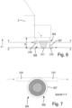
- Fig. 6 shows a cross-section of a schematic representation of part of a high-shear granulator 2 with a third embodiment of a screening device 304 according to the invention arranged on the high-shear granulator 2.
- the inlet opening 316 for the transfer air is arranged tangentially on the cylindrical screen housing 308 of the screening device 304.
- the outlet opening 310 is also arranged tangentially on the cylindrical screen housing 308 of the screening device 304.
- the inlet opening 316 lies in the horizontal sectional plane YY through the screening device 304
- the outlet opening 310 lies in the likewise horizontal sectional plane ZZ through the screening device 304.
- the horizontal sectional planes YY and ZZ are offset from one another above the overall height H of the screen housing 308 of the screening device 304.
- transfer air is supplied to the sieve housing 308 of the sieve device 304 through the inlet opening 316 and is located at a higher position in the x-direction of the sieve housing 308 of the sieve device 304 compared to the outlet of the sieved granulate through the outlet opening 310 of the sieve housing 308 of the sieve device 304.
- the granulate enters the screening device 304 from the high-shear granulator 2 and is pressed through the screen 311 by a grinding body 314 (not shown here) with a constant pressure continuously distributed across the screen 311. Transfer air also enters the screen housing 304 of the screening device 308 through the inlet opening 316 arranged in the upper region of the screen housing 308 tangentially to the side wall 307 of the screen housing 308, and a spiral-shaped, downward air flow is generated within the cylindrical screen housing 308 of the screening device 304, counter to the x-direction.
- This air flow transports, on its way through the sieve housing 308, for example, granules adhering to or deposited on the sieve housing 308 in the direction of the outlet opening 310 and thus prevents the sieve device 304 from becoming blocked by the granules themselves.
- the outlet opening 310 arranged tangentially on the side wall 307 of the sieve housing 308 also ensures optimal suction of the granules and the transfer air.
- a top view of the Fig. 6 1 shows a schematic representation of a screening device 304 according to the invention arranged on a high-shear granulator 2 according to a third exemplary embodiment. It can be seen that the inlet opening 316 for transfer air and the outlet opening 310 for the product are arranged on the same side of the screening housing 308. Furthermore, both the inlet opening 316 and the outlet opening 310 extend tangentially to the side wall 307 of the screening housing 308 of the screening device 304.
Landscapes
- Engineering & Computer Science (AREA)
- Mechanical Engineering (AREA)
- Food Science & Technology (AREA)
- Combined Means For Separation Of Solids (AREA)
- Disintegrating Or Milling (AREA)
- Separation Of Solids By Using Liquids Or Pneumatic Power (AREA)
- Glanulating (AREA)
- Filtering Of Dispersed Particles In Gases (AREA)
- Drying Of Solid Materials (AREA)
Description
- Die Erfindung betrifft eine Siebvorrichtung für das Sieben von Granulat, insbesondere feuchtem und/oder trockenem Granulat, umfassend ein einen Boden, einen Deckel und eine Seitenwand aufweisendes Siebgehäuse, eine am Siebgehäuse angeordnete Eintrittsöffnung für das Granulat, eine am Siebgehäuse angeordnete Austrittsöffnung für das gesiebte Granulat, ein im Siebgehäuse angeordnetes Sieb und eine am Siebgehäuse angeordnete Einlassöffnung für Transferluft.
- Siebvorrichtungen für Granulate, insbesondere für einen einem Nassgranulationsprozess oder einem Trocknungsprozess in einem Fluidisierungsapparat nachgeschalteten Siebvorgang, sind seit langem Stand der Technik. Die bekannten Siebvorrichtungen werden über eine am Deckel der Siebvorrichtung angeordnete Eintrittsöffnung für das Granulat befüllt und über eine im Boden der Siebvorrichtung nach einem Saugschuh angeordnete Austrittsöffnung nach dem Siebvorgang entleert. Hierbei erfolgt der Transport des Granulats von der Eintrittsöffnung zur Austrittsöffnung beispielsweise über eine Schwerkraftbeschickung oder über eine pneumatische Förderung.
-
EP 0 159 050 A1 offenbart eine Vorrichtung zum Trennen von Korngut in Fraktionen unterschiedlicher Wichte. Die Vorrichtung weist hierzu zwei übereinander angeordnete, luftdurchlässige und schwingfähig gelagerte Wirbelschichttische auf. Der obere Wirbelschichttisch mit dem Korngut über einen Einlauf beschickt, dem ein Auslauf die leichte Fraktion gegenüberliegt. Der untere Wirbelschichttisch, weist einen Auslauf für die schwere Kornfraktion auf, dem am anderen Ende ein Auslauf für die schwerste Kornfraktion gegenüberliegt. Zur Steigerung der Trennqualität wird vorgeschlagen, dass der obere Wirbelschichttisch in Richtung vom Einlauf gegen den Auslauf für die leichte Kornfraktion in mindestens zwei sich folgende Bereiche unterschiedlicher Lochung eingeteilt ist. Die Lochung des oberen Wirbelschichttisches ist derart ausgebildet, dass die erwähnten Kornfraktionen nur in dem bzw. den dem ersten Bereich folgenden Bereichen hindurchfallen können. Zwischen den Wirbelschichttisches und unter dem zweiten Bereich ist, eine sich über deren Breite erschreckender Boden angeordnet, wobei an dem Einlauf gegenüberliegenden Ende des Bodens ein Auslauf für eine mittelschwere Kornfraktion anschließt. - In der
CN 106 670 107 A offenbart eine Verunreinigungsentfernungsbox zum Zuführen von Rohstoffen, wobei die Verunreinigungsentfernungsbox ein Gehäuse, einen Siebmechanismus, einen Antriebsmechanismus und ein Luftgebläse umfasst; im oberen Ende des Gehäuses ist eine Zuführöffnung ausgebildet; das Gehäuse ist ferner mit einer Ablassöffnung, einem Lufteinlass und einem Luftauslass versehen; der Lufteinlass und der Luftauslass befinden sich unterhalb des Zuführstutzens; der Luftauslass ist kleiner als der Lufteinlass und der Luftauslass; der Siebmechanismus ist innerhalb des Gehäuses angeordnet und mit einer Siebwelle und mehreren Lagen grober Siebsiebe versehen; die Siebwelle ist drehbar an dem Gehäuse gelagert; die mehreren Lagen grober Siebsiebe sind von oben nach unten auf der Siebwelle gelagert; die Maschen aller Grobsiebsiebe werden sequentiell von oben nach unten vergrößert; und der Antriebsmechanismus dazu dient, die Siebwelle in Rotation zu versetzen. Mit der Verunreinigungsentfernungsbox werden einerseits, Staub und leichte Verunreinigungen, die in den Einsatzrohstoffen gemischt werden, durch von dem Luftgebläse erzeugte Luftströme abgeführt, und andererseits sind die mehreren Lagen von drehbaren Grobsiebsieben zum Sieben und Trennen der Aufgaberohstoffe und der festen Verunreinigungen angeordnet, so dass die Verunreinigungsentfernungsbox bequem zu bedienen ist und die gute Fremdstofftrennwirkung aufweist. -
WO 2004/048006 A1 betrifft ein Verfahren und eine Vorrichtung zum Abtrennen von Staubpartikeln aus einem Granulat. Hierzu wird eine in einem Behälter angeordnete Siebtrommel mit dem Granulat in einer Befüllposition befüllt. In einer Betriebsposition wird das Granulat durch einen Luftstrom, der über die Luftzuführungen in die Vorrichtung einströmt in der Siebtrommel vom Staub gereinigt. In einer Entleerposition wird das entstaubte Granulat über die Entleeröffnung aus der Vorrichtung entnommen. - In der
FR 462 736 A -
WO 91/08059 A1 - In der
US 6 216 875 B1 wird eine einen an der Seitenwand angeordneten Transferlufteintritt aufweisende Siebvorrichtung gezeigt. -
US 2004/056128 A1 offenbart eine Schlagmühle, die ein zylindrisches Gehäuse aufweist, in dem sowohl ein polygonales Sieb als auch ein das polygonale Sieb umschließendes rundes Sieb angeordnet sind. Das zu siebende Material wird über den Einlass der Schlagmühle zugeführt und mittels der am Gehäuseboden angeordneten, rotierenden Schiebe und der diese umgebenden Leitschaufeln zerkleinert und dann durch die Siebe in Richtung Auslass gefördert. Die Förderung des zu siebenden Materials wird durch Transferluftzugabe am Einlass verbessert. -
CH 631 358 A5 - Nachteilig an solchen aus dem Stand der Technik bekannten Siebvorrichtungen für Granulate, bei denen das z. B. feuchte Granulat in einen Trockner zu überführen ist, ist, dass diese Siebvorrichtungen eine große Bauhöhe aufweisen bzw. erfordern und somit auch eine räumliche Möglichkeit zur Realisierung einer mit einer bekannten Siebvorrichtung ausgestatteten verfahrenstechnischen Anlage gegeben sein muss. Darüber hinaus ist bei den bekannten Siebvorrichtungen von Nachteil, dass durch die zumindest teilweise konische Form des Saugschuhs des Siebgehäuses der bekannten Siebvorrichtung durch Anhaftungen bzw. Ablagerungen von Granulat im dem konisch geformten Bereich (Saugschuh) des Siebgehäuses der Produkttransfer an gesiebtem Granulat deutlich eingeschränkt wird.
- Aufgabe der Erfindung ist es eine Siebvorrichtung bereitzustellen, die bei gleichzeitiger Minimierung der Anhaftungen bzw. Ablagerungen von Granulat am Siebgehäuse eine geringere Bauhöhe erfordert und somit die Nachteile aus dem Stand der Technik beseitigt.
- Diese Aufgabe wird bei einer Siebvorrichtung gemäß Anspruch 1 gelöst.
- Vorteilhafterweise wird dadurch die erforderliche Bauhöhe der Siebvorrichtung deutlich verringert, wodurch sich ein Einbau in bereits bestehende beispielsweise verfahrenstechnische Anlagen einfacher gestaltet. Die Bauhöhe wird beispielsweise durch den Wegfall des nach dem Stand der Technik notwendigen konischen Bereichs unterhalb des Siebs, der auch als Saugschuh bezeichnet wird, deutlich reduziert. Hierdurch wird eine Anhaftung bzw. Ablagerung von Granulat im Siebgehäuse, insbesondere aber im Bereich der Austrittsöffnung des gesiebten Granulats verhindert, wodurch während des gesamten Betriebs stets ein ausreichend schneller und ausreichend guter Produkttransfer an gesiebten Granulat ermöglicht wird.
- Durch die erfindungsgemäße kompakte Bauweise wird zum einen die erforderliche Bauhöhe der Siebvorrichtung aufgrund des Wegfalls des Saugschuhs eingespart und gleichzeitig zusätzlich die produktberührte innere Oberfläche des Siebgehäuses verringert.
- Besonders bevorzugt dient die erfindungsgemäße Siebvorrichtung zum Sieben von feuchtem und/oder trockenem Granulat, besonders bevorzugt für einen einem Nassgranulationsprozess oder einem Trocknungsprozess in einem Fluidisierungsapparat, beispielsweise in einer Wirbelschicht oder dgl., nachgeschalteten Siebvorgang.
- Das Siebgehäuse weist in einer vorteilhaften Ausgestaltung eine zylindrische Bauform auf, wobei die Seitenwand des Siebgehäuses zumindest teilweise konisch geformt ist. Durch eine derartige geometrische Ausgestaltung der Siebvorrichtung wird weiterer u. a. Bauraum eingespart, wodurch die erfindungsgemäße Siebvorrichtung noch besser in bereits bestehende Anlagen integrierbar ist.
- Insbesondere hat sich gezeigt, dass besonders bevorzugt die am Siebgehäuse angeordnete Austrittsöffnung für das gesiebte Granulat (Produkt) tangential an der Seitenwand des Siebgehäuses angeordnet ist. Durch die tangentiale Anordnung der Austrittsöffnung für das Granulat an der Seitenwand des Siebgehäuses wird eine optimierte Abführung des gesiebten Granulats erzielt. Zudem werden durch die tangentiale Anordnung Anhaftungen bzw. Ablagerungen im Bereich der Austrittsöffnung minimiert und ein schneller und unproblematischer Transport des gesiebten Granulats gewährleistet.
- Die Austrittsöffnung für das gesiebte Granulat ist in einer bevorzugten Ausführungsform oberhalb der Einlassöffnung für Transferluft angeordnet ist. Durch die tangentiale Strömung/Bewegung der Transferluft im Siebgehäuse wirken die Fliehkräfte auf das Granulat und treiben bzw. befördern es nach oben. Hierdurch ist es vorteilhaft die Austrittsöffnung für das gesiebte Granulat (Produkt) oberhalb der Einlassöffnung für die Transferluft anzuordnen.
- Zusätzlich ist vorzugsweise die Siebvorrichtung derart ausgestaltet, dass das im Siebgehäuse angeordnete Sieb entsprechend der Bauform des Siebgehäuses ausgebildet ist. Hierdurch wird die produktberührte innere Oberfläche des Siebgehäuses reduziert, d. h. die möglichen Plätze für Anhaftungen bzw. Ablagerungen im Siebgehäuse werden miniert, so dass ein schneller und unproblematischer Transport des gesiebten Granulats gewährleistet wird.
- In einer besonderen Ausgestaltung der erfindungsgemäßen Siebvorrichtung weist die Siebvorrichtung einen insbesondere im Siebgehäuse angeordneten Mahlkörper auf. Der Vorteil eines im Siebgehäuse angeordneten Mahlkörpers besteht darin, dass durch diesen das Granulat verbessert durch das Sieb gepresst werden kann. Durch den Mahlkörper wird also der Siebvorgang optimiert.
- In einer diesbezüglich bevorzugten Ausführungsform der Siebvorrichtung ist der im Siebgehäuse angeordnete Mahlkörper oberhalb des Siebs angeordnet. Der im Siebgehäuse angeordnete Mahlkörper ist rotierbar angeordnet, besonders bevorzugt ist der Mahlkörper über einen Motor, insbesondere einen Elektromotor oder dgl., antreibbar. Hierdurch wird der Siebvorgang weiter optimiert.
- Der im Siebgehäuse angeordnete Mahlkörper ist besonders bevorzugt entsprechend der Bauform des Siebs ausgebildet. Diese Anpassung des Mahlkörpers an die Form des Siebs verbessert die Durchführung des Siebvorgangs in deutlichem Umfang, da das zu siebende Granulat mittels des an die Form des Siebs angepassten Mahlkörpers unter einem kontinuierlichen und gleichbleibenden Druck durch das Sieb gedrückt wird.
- In einer zusätzlichen bevorzugten Ausführungsform der erfindungsgemäßen Siebvorrichtung weist die Siebvorrichtung eine Einlassöffnung für Transferluft auf, wobei die Einlassöffnung für Transferluft vorzugsweise an der Seitenwand des Siebgehäuses, besonders bevorzugt tangential an der Seitenwand des Siebgehäuses, angeordnet ist. Als Transferluft werden gasförmige Medien, vorzugsweise Luft aber auch inerte Gase, bezeichnet. Durch die Zufuhr von Transferluft wird der Produkttransport verbessert. Zudem wird im Siebgehäuse der Siebvorrichtung eine Luftströmung erzeugt, die Anhaftungen bzw. Ablagerungen von Granulat an der inneren Oberfläche des Siebgehäuses minimiert bzw. ganz verhindert. Insbesondere die vorzugsweise seitliche, besonders bevorzugt aber tangentiale Anordnung der Einlassöffnung für Transferluft erzeugt sehr gute Strömungsverhältnisse der Transferluft im Siebgehäuse zur Verhinderung der Anhaftungen bzw. Ablagerungen von Granulat und in Bezug auf den Granulattransport durch die Austrittsöffnung.
- Nach einer weiteren bevorzugten Ausführungsform der erfinderischen Siebvorrichtung weist die Siebvorrichtung eine Rotorscheibe auf, die insbesondere zwischen dem im Siebgehäuse angeordneten Sieb und dem Boden des Siebgehäuses angeordnet ist und besonders bevorzugt zumindest teilweise konusförmig ausgebildet ist. Der Vorteil einer zwischen Sieb und Boden im Siebgehäuse angeordneten Rotorscheibe liegt darin, dass diese zum Schutz der Dichtung unterhalb des Siebes dient und um zu verhindern, dass Produkt auf dem Boden, d. h. auf der unteren horizontalen Ebene des Siebgehäuses, liegenbleibt, ist eine Rotorscheibe.
- Besonders bevorzugt ist die Rotorscheibe auf einer über einen Motor antreibbaren Welle angeordnet, wodurch ein verbesserter Transfer des gesiebten Granulats sichergestellt wird.
- Nachfolgend wird die Erfindung anhand der beiliegenden Zeichnung näher erläutert. In dieser zeigen:
- Figur 1
- eine einfache schematische Darstellung eines prinzipiellen Aufbaus einer aus dem Stand der Technik bekannten Granulationslinie mit einer Siebvorrichtung am Austritt eines High-Shear Granulierers,
- Figur 2
- einen Querschnitt einer Detailansicht einer aus dem Stand der Technik bekannte Siebvorrichtung gemäß Ausschnitt A der
Fig. 1 , - Figur 3
- einen Querschnitt eines ersten Ausführungsbeispiels einer erfindungsgemäßen Siebvorrichtung mit einer seitlich am Siebgehäuse angeordneten Austrittsöffnung für das Granulat und einer seitlich am Siebgehäuse angeordneten Einlassöffnung für Transferluft,
- Figur 4
- einen Querschnitt eines zweiten Ausführungsbeispiels einer erfindungsgemäßen Siebvorrichtung mit einer im Siebgehäuse angeordneten Rotorscheibe und einer seitlich am Siebgehäuse angeordneten Austrittsöffnung für das Granulat gemäß Schnittebene X-X in
Fig. 5 , - Figur 5
- eine Draufsicht auf das zweite Ausführungsbeispiel der erfindungsgemäßen Siebvorrichtung mit einer seitlich am Siebgehäuse angeordneten Austrittsöffnung für das Granulat und einer seitlich am Siebgehäuse angeordneten Einlassöffnung für Transferluft,
- Figur 6
- einen Querschnitt einer schematischen Darstellung eines High-Shear Granulierers mit daran angeordneter erfindungsgemäßer Siebvorrichtung, und
- Figur 7
- eine Draufsicht auf die in
Fig. 5 gezeigte schematische Darstellung einer an einem High-Shear Granulierer angeordneten erfindungsgemäßen Siebvorrichtung. - In der
Fig. 1 wird eine einfache schematische Darstellung eines prinzipiellen Aufbaus einer aus dem Stand der Technik bekannten Granulationslinie 1 dargestellt. Um beispielsweise das feuchte Granulat aus einem High-Shear Granulierer 2 in einen Trockner 3 zu überführen ist ein Transfer des Granulats notwendig. Dieser Transfer wird derzeit entweder über eine Schwerkraftbeschickung des Trockners 3 oder über eine pneumatische Förderung realisiert. Im Falle einer Schwerkraftbeschickung fällt das Granulat durch die eigene Masse getrieben in den Trockner 3. Diese Art der Beschickung erfordert jedoch eine große Bauhöhe und die räumliche Möglichkeit der Realisierung der Granulationslinie 1. Bei der inFig. 1 gezeigten Granulationslinie 1 ist zwischen dem High-Shear Granulierer 2 und dem Trockner 3 eine Siebvorrichtung 4 am Austritt des High-Shear Granulierers 2 gezeigt. Der Austritt der Siebvorrichtung 4 ist mit dem Trockner 3 über eine flexible Schlauchleitung 5 verbunden. -
Fig. 2 zeigt einen Querschnitt einer Detailansicht einer aus dem Stand der Technik bekannten Siebvorrichtung 4 gemäß Ausschnitt A derFig. 1 zur Durchführung eines Siebvorgangs von Granulat, insbesondere für einen einem Nassgranulationsprozess oder einem Trocknungsprozess in einer Wirbelschicht nachgeschalteten Siebvorgang. - Die Siebvorrichtung 4 umfasst ein einen Deckel 6 und eine Seitenwand 7 aufweisendes Siebgehäuse 8. Das Siebgehäuse 8 weist darüber hinaus zusätzlich eine im Deckel 6 des Siebgehäuses 8 angeordnete Eintrittsöffnung 9 für das Granulat und eine am Siebgehäuse 8 angeordnete Austrittsöffnung 10 auf. Im Siebgehäuse 8 ist ein Sieb 11 zum Sieben des Granulats so angeordnet, dass das über die Eintrittsöffnung 9 eintretende Granulat komplett durch das Sieb 11 aufgenommen wird. Im Siebgehäuse 8 ist dem Sieb 11 zudem ein auf einer Welle 12 über einen Motor M in Pfeilrichtung 13 rotierbar angetriebener Mahlkörper 14 zugeordnet. Um den Transfer des Granulats beispielweise in einen Trockner 3 nach dem Sieben zu gewährleisten wird oberhalb und unterhalb des Siebs 11 der Siebvorrichtung 4 über Einlassöffnungen Transferluft zugeführt. Die Zuführung von Transferluft zur Siebvorrichtung 4 wird oberhalb des Siebes 11 über eine im Deckel 6 angeordnete erste Einlassöffnung 15 und über eine nach dem Sieb 11 angeordnete zweite Einlassöffnung 16 realisiert.
- Das Granulat, das über die im Deckel 6 angeordnete Eintrittsöffnung 9 in die Siebvorrichtung 4 entleert wird, wird durch den rotierenden Mahlkörper 14 durch die Maschen des Siebs 11 gepresst. Zu Beginn der Entleerung des Granulats des im Ausführungsbeispiel vorgeschalteten High-Shear Granulierers 2 wird das meiste Granulat auf einmal in das Sieb 11 der Siebvorrichtung 4 entleert. Hierdurch kommt es vor und nach dem im Siebgehäuse 8 angeordneten Sieb 11 häufig zur Verblockung der Eintrittsöffnung 9 und der Austrittsöffnung 10 der Siebvorrichtung 4. Die Verblockungen entstehen beispielsweise aufgrund von Anhaftungen bzw. Ablagerungen von Granulat an der von Granulat berührten inneren Oberfläche 17 des Siebgehäuses 8, bevorzugt im konisch ausgebildeten Bereich 18 des Siebgehäuses 8, da der konisch ausgebildete Bereich 18 die für das Granulat vorhandene Durchtrittsfläche des Siebgehäuses 8 hin zu der Austrittsöffnung 10 des Siebgehäuses 8 stark reduziert. Beispielsweise wird in realen Anwendungen der Durchmesser des Siebgehäuses 4 von 400 mm auf einen Durchmesser der Austrittsöffnung 10 von 100 mm reduziert. Weiterhin bilden sich bei der aus dem Stand der Technik bekannten Ausgestaltung der Siebvorrichtung 4 meist verrundete Brocken von Granulat, die nicht durch das Sieb 11 befördert werden können und somit als Verlust im Sieb 11 verbleiben.
- In
Fig. 3 ist ein Querschnitt eines ersten Ausführungsbeispiels einer erfindungsgemäßen Siebvorrichtung 104 mit einer seitlich am Siebgehäuse 108 angeordneten Austrittsöffnung 110 für das zu siebende Granulat und einer seitlich am Siebgehäuse 108 angeordneten Einlassöffnung 116 für Transferluft abgebildet. - Die erfindungsgemäße Siebvorrichtung 104 für die Durchführung eines Siebevorgangs von Granulat, insbesondere für einen einem Nassgranulationsprozess oder einem Trocknungsprozess in einer Wirbelschicht nachgeschalteten Siebvorgang, gemäß dem ersten Ausführungsbeispiel umfasst ein einen Boden 119, einen Deckel 106 und eine Seitenwand 107 aufweisendes Siebgehäuse 108. Zusätzlich weist die Siebvorrichtung 104 eine am Siebgehäuse 108 angeordnete Eintrittsöffnung 109, eine am Siebgehäuse 108 angeordnete Austrittsöffnung 110, ein im Siebgehäuse 108 angeordnetes Sieb 111 und einen im Siebgehäuse 108 angeordneten Mahlkörper 114 auf, wobei die am Siebgehäuse 108 angeordnete Austrittsöffnung 110 in der einteilig ausgeführten Seitenwand 107 des Siebgehäuses 108, besonders bevorzugt tangential an der Seitenwand 107 des Siebgehäuses 108, angeordnet ist. Während der Produktfluss nach der im Stand der Technik bekannten Siebvorrichtung von oben nach unten erfolgte, wird in der erfindungsgemäßen neuen Geometrie der Siebvorrichtung 104 das gesiebte Granulat durch die an der Seitenwand 107 des Siebgehäuses 108 angeordneten Austrittsöffnung 110 abgesaugt.
- Im Ausführungsbeispiel gemäß
Fig. 3 weist das Siebgehäuse 108 eine zylindrische, über seine gesamte Bauhöhe H konische, sich vom Deckel 106 zum Boden 118 des Siebgehäuses 108 verjüngende Bauform auf. Andere Ausgestaltungen der Bauform sind denkbar. Die Seitenwand 107 ist im ersten Ausführungsbeispiel einteilig als konisch ausgeformte Seitenwand 107 ausgeführt. Die Seitenwand 107 kann aber auch mehrteilig, d. h. zumindest zwei Seitenwandabschnitte aufweisend, ausgeführt sein. Außerdem können auch mehrere Eintrittsöffnungen 109 und Austrittsöffnungen 110 am Siebgehäuse 108 angeordnet sein. Die Anzahl, Lage und/oder Geometrie der Eintrittsöffnungen 109 ist variabel. In Bezug auf die Austrittsöffnungen 110 ist zumindest die Anzahl und/oder die Geometrie variabel. Die Lage der Austrittsöffnungen 110 ist zumindest dahingehend eingeschränkt, dass mindestens eine der Austrittsöffnungen 110 seitlich am Siebgehäuse 108 angeordnet ist. - Die in
Fig. 3 gezeigte Siebvorrichtung 104 umfasst zudem einen auf einer, vorzugsweise über einen Motor M, besonders bevorzugt über einen Elektromotor oder dgl., in Pfeilrichtung 113 rotierbar angetriebenen Welle 112 gelagerten Mahlkörper 114. Der Mahlkörper 114 ist dem Sieb 111 in seiner Form angepasst, so dass das Granulat verbessert unter kontinuierlich gleichbleibendem Druck vom Mahlkörper 114 durch die Maschen des Siebs 111 pressbar ist. Für einen zusätzlich verbesserten Transfer des zu siebenden Granulats durch die das Sieb 111 aufweisende Siebvorrichtung 104 wird der Siebvorrichtung 104 Transferluft über die Einlassöffnung 116 zu geführt. Im Ausführungsbeispiel ist eine Einlassöffnung 116 an der Seitenwand 107 des Siebgehäuses 108 angeordnet. Die Einlassöffnung 116 ist auch in Anzahl, Lage und/oder Geometrie variabel ausführbar. Vorzugsweise ist die Einlassöffnung der Transferluft 116 unterhalb der Austrittsöffnung 110 für das gesiebte Granulat (Produkt), also genau umgekehrt wie inFig. 3 dargestellt, seitlich am Siebgehäuse 108 angeordnet. Durch die tangentiale Bewegung der Luft wirken die Fliehkräfte auf das Granulat und treiben bzw. befördern es nach oben in Richtung der vorzugsweise oberhalb Einlassöffnung der Transferluft 116 angeordneten der Austrittsöffnung 110. - Die Geometrie von Siebgehäuse 108, Sieb 111 und/oder Mahlkörper 114 sind vorzugsweise, wie auch im ersten Ausführungsbeispiel ausgeführt, aufeinander abgestimmt, um den Siebvorgang weiter zu optimieren. Durch die Abstimmung der unterschiedlichen Geometrien aufeinander wird neben einer Reduktion der Bauhöhe durch Verzicht auf einen zusätzlichen Saugschuh auch die innere freie Oberfläche der Siebvorrichtung, insbesondere des Siebgehäuses, minimiert.
- Das Granulat tritt im in
Fig. 3 gezeigten ersten Ausführungsbeispiel über die Eintrittsöffnung 109 in die Siebvorrichtung 104 ein. Aufgrund der aufeinander abgestimmten Geometrien von Siebgehäuse 108, Sieb 111 und Mahlkörper 114 bilden sich wenige Anhaftungen bzw. Ablagerungen, da die vom Granulat während des Siebvorgangs berührte innere Oberfläche 117 minimal ist. Zusätzlich bilden sich in Umfangsrichtung des Siebgehäuses 108 weniger Granulatanhaftungen bzw. -ablagerungen oder werden schneller über die Austrittsöffnung 110 weitertransportiert, da durch die seitlich über die Einlassöffnung 116 einströmende Transferluft in Verbindung mit der minimalen berührten inneren Oberflächen 117 optimierte Strömungsverhältnisse im Siebgehäuse 108 herstellbar sind. Das gesiebte Granulat wird durch die an der Seitenwand 107 des Siebgehäuses 108 angeordnete Austrittsöffnung 110 abgesaugt. -
Fig. 4 zeigt einen Querschnitt eines zweiten Ausführungsbeispiels einer erfindungsgemäßen Siebvorrichtung 204 mit einer im Siebgehäuse 208 angeordneten Rotorscheibe 220 und einer seitlich am Siebgehäuse 208 angeordneten Austrittsöffnung 210 für das Granulat gemäß Schnittebene X-X inFig. 5 . - Auch das zweite erfindungsgemäße Ausführungsbeispiel umfasst wie auch das erste Ausführungsbeispiel ein einen Boden 219, einen Deckel 206 und eine Seitenwand 207 aufweisendes Siebgehäuse 208. Die Siebvorrichtung 204 weist zudem zusätzlich eine am Siebgehäuse 208 angeordnete Eintrittsöffnung 209 für das Granulat, eine am Siebgehäuse 208 angeordnete Austrittsöffnung 210 für das gesiebte Granulat (Produkt), ein im Siebgehäuse 208 angeordnetes Sieb 211 und einen im Siebgehäuse 208 dem Sieb 211 zugeordneten Mahlkörper 214 auf, wobei die am Siebgehäuse 208 angeordnete Austrittsöffnung 210 für das gesiebte Granulat in der Seitenwand 207 des Siebgehäuses 208 angeordnet ist, besonders bevorzugt tangential zur Seitenwand 207 des Siebgehäuses 208. Der dem Sieb 211 zugeordnete Mahlkörper 214 ist an einer über einen Motor M, vorzugsweise ein Elektromotor oder dgl., in Pfeilrichtung 213 rotierbar angetriebenen Welle 212 angeordnet. Der Mahlkörper 214 ist oberhalb des Siebs 211 im Siebgehäuse 208 angeordnet, wodurch das zu siebende Granulat kontinuierlich mit konstantem Druck durch das Sieb 211 gepresst wird. Auch die Siebvorrichtung 204 des zweiten Ausführungsbeispiels gemäß
Fig. 4 weist eine hier nicht gezeigte Einlassöffnung 216 für Transferluft auf. - Die zum ersten erfindungsgemäßen Ausführungsbeispiel getroffenen Ausführungen in Bezug auf die Seitenwände, Einlass, Einritts- und Austrittsöffnungen usw. sind auf das zweite erfindungsgemäße Ausführungsbeispiel in gleichem Maße übertragbar.
- Die erfindungsgemäße Siebvorrichtung 204 gemäß dem zweiten Ausführungsbeispiel weist eine zylindrische Bauform des Siebgehäuses 208 auf, wobei die Bauform des Siebgehäuses 208 der Siebvorrichtung 204 über der Bauhöhe H des Siebgehäuses 208 konisch vom Deckel 206 zum Boden 219 verjüngend ausgestaltet ist. Das in dem Siebgehäuse 208 der Siebvorrichtung 204 angeordnete Sieb 211 ist der Bauform des Siebgehäuses 208 entsprechend ausgebildet. Zudem ist der im Siebgehäuse 208 der Siebvorrichtung 204 angeordnete Mahlkörper 214 der Bauform des Siebs 211 entsprechend ausgebildet. Hierdurch sind Siebgehäuse 208, Sieb 211 und Mahlkörper 214 optimal aufeinander abgestimmt.
- Im Gegensatz zur Siebvorrichtung 104 des ersten Ausführungsbeispiels weist die Siebvorrichtung 204 zusätzlich eine Rotorscheibe 220 auf. Die Rotorscheibe 220 ist hierbei zwischen dem Sieb 211 und dem Boden 219 des Siebgehäuses 208 der Siebvorrichtung 204 angeordnet. Die Rotorscheibe 220 ist auf einer über den Motor M antreibbaren Welle 212 angeordnet. Somit sind Rotorscheibe 220 und Mahlkörper 2014 auf einer Welle 212 gelagert und werden immer mit derselben Rotationsgeschwindigkeit angetrieben. Es ist zudem denkbar, dass die Rotorscheibe 220 und der Mahlkörper 214 des Siebes 211 unabhängig voneinander, beispielsweise über jeweils über einen separaten Motor, insbesondere einen Elektromotor oder dgl., antreibbar sind. Hierbei sind die Rotorscheibe 220 und der Mahlkörper 214 auf verschiedenen Wellen angeordnet. Vorzugsweise ist die Rotorscheibe 220 der Siebvorrichtung 204 zumindest teilweise konusförmig ausgebildet. Die Anordnung der Rotorscheibe 220 dient zum Schutz der Dichtung unterhalb des Siebes 211 und um zu verhindern, dass Produkt auf dem Boden 219 liegenbleibt und nicht weiter Richtung der Absaugung der Austrittsöffnung 210 transportiert wird. Hierdurch wird ein noch besserer und vollständiger Transfer des Produkts erzielt und Anhaftungen bzw. Ablagerungen des Granulats im Bereich des Bodens 211 des Siebgehäuses 208 sowie der Seitenwand 207 des Siebgehäuses 208 minimiert.
- Eine weitere Verbesserung des Produkttransfers wird dadurch erreicht, dass die hier nicht gezeigte Einlassöffnung 216 für Transferluft an der Seitenwand 207 des Siebgehäuses 208 angeordnet ist, vorzugsweise ist die hier nicht gezeigte Einlassöffnung 216 für Transferluft tangential an der Seitenwand 207 des Siebgehäuses 208 angebracht.
- In
Fig. 5 ist eine Draufsicht auf das zweite Ausführungsbeispiel der erfindungsgemäßen Siebvorrichtung 204 mit einer seitlich am Siebgehäuse 208 angeordneten Austrittsöffnung 210 für das Granulat und einer Einlassöffnung 216 für Transferluft abgebildet. Der über eine von einem Motor M angetriebene auf einer Welle 212 angeordnete Mahlkörper 214 ist oberhalb des Siebes 211 im Siebgehäuse 208, das einen hier nicht gezeigten Deckel 206 und einen nicht dargestellten Boden 219 sowie eine Seitenwand 207 aufweist, angeordnet und befindet sich in der Schnittebene X-X. Von der Schnittebene X-X seitlich versetzt ist die Einlassöffnung 216 für die Transferluft an der Seitenwand 207 des Siebgehäuses 208 angeordnet. - Durch die Rotation des Mahlkörpers 214 in Pfeilrichtung 213 wird das Granulat durch das Sieb 211 gepresst bzw. gedrückt. Optimiert wird der Siebvorgang durch die in die Einlassöffnung 216 eintretende Transferluft. Die Kombination aus rotierendem Mahlkörper 214 und Transferluft ergibt einen verbesserten Siebprozess des Granulats.
-
Fig. 6 zeigt einen Querschnitt einer schematischen Darstellung eines Teils eines High-Shear Granulierers 2 mit einem dritten Ausführungsbeispiel einer am High-Shear Granulierer 2 angeordneten erfindungsgemäßen Siebvorrichtung 304. Die Einlassöffnung 316 für die Transferluft ist tangential am zylindrischen Siebgehäuse 308 der Siebvorrichtung 304 angeordnet. Ebenfalls tangential ist auch die Austrittsöffnung 310 am zylindrischen Siebgehäuse 308 der Siebvorrichtung 304 angeordnet. Die Einlassöffnung 316 liegt im Ausführungsbeispiel in der horizontalen Schnittebene Y-Y durch die Siebvorrichtung 304, die Austrittsöffnung 310 liegt im dritten Ausführungsbeispiel in der ebenfalls horizontalen Schnittebene Z-Z durch die Siebvorrichtung 304. Im dritten Ausführungsbeispiel sind die horizontalen Schnittebenen Y-Y und Z-Z über der Bauhöhe H des Siebgehäuses 308 der Siebvorrichtung 304 zueinander versetzt. Ein solcher Versatz zwischen den Schnittebenen Y-Y und Z-Z ist jedoch nicht zwingend erforderlich. Die Transferluft wird im dritten Ausführungsbeispiel dem Siebgehäuse 308 der Siebvorrichtung 304 durch die Einlassöffnung 316 zugeführt und liegt im Vergleich zum Austritt des gesiebten Granulats durch die Austrittsöffnung 310 des Siebgehäuses 308 der Siebvorrichtung 304 an einer in x-Richtung höher gelegenen Position des Siebgehäuses 308 der Siebvorrichtung 304. - Die zum ersten erfindungsgemäßen Ausführungsbeispiel getroffenen Ausführungen in Bezug auf die Seitenwände, Einlass, Einritts- und Austrittsöffnungen usw. sind auf das dritte erfindungsgemäße Ausführungsbeispiel in gleichem Maße übertragbar.
- Das Granulat tritt vom High-Shear Granulierer 2 kommend in die Siebvorrichtung 304 ein und wird von einem hier nicht dargestellten Mahlkörper 314 durch das Sieb 311 mit kontinuierlich über dem Sieb 311 verteiltem konstantem Druck gedrückt. Durch die im oberen Bereich des Siebgehäuses 308 tangential zur Seitenwand 307 des Siebgehäuses 308 angeordnete Einlassöffnung 316 tritt zusätzlich Transferluft in das Siebgehäuse 304 der Siebvorrichtung 308 ein und es wird eine entgegen der x-Richtung spiralförmig abwärts verlaufende Luftströmung innerhalb des zylindrischen Siebgehäuses 308 der Siebvorrichtung 304 erzeugt. Diese Luftströmung transportiert auf dem Weg durch das Siebgehäuse 308 beispielweise an dem Siebgehäuse 308 anhaftendes bzw. abgelagertes Granulat mit in Richtung Austrittsöffnung 310 und verhindert somit eine Verblockung der Siebvorrichtung 304 durch das Granulat selbst. Durch die tangential an der Seitenwand 307 des Siebgehäuses 308 angeordnete Austrittsöffnung 310 wird zudem für eine optimale Absaugung der des Granulats und der Transferluft gewährleistet.
- In
Fig. 7 wird eine Draufsicht auf die inFig. 6 gezeigte schematische Darstellung einer an einem High-Shear Granulierer 2 angeordneten erfindungsgemäßen Siebvorrichtung 304 gemäß drittem Ausführungsbeispiel gezeigt. Hierbei ist ersichtlich, dass die Einlassöffnung 316 für Transferluft und die Austrittsöffnung 310 für das Produkt auf der gleichen Seite des Siebgehäuses 308 angeordnet sind. Darüber hinaus verlaufen sowohl die Einlassöffnung 316 als auch die Austrittsöffnung 310 tangential zum Seitenwand 307 des Siebgehäuses 308 der Siebvorrichtung 304. - Bei jeder der verwendeten Geometrie der erfindungsgemäßen Siebvorrichtungen 104, 204 und 304 ist es ausreichend die Transferluft, vorzugsweise über eine tangential an der Seitenwand 107, 207 oder 307 angeordnete Austrittsöffnung 110, 210 oder 310 anzusaugen und dadurch einen schnellen und sicheren Produkttransfer zu erreichen.
Claims (15)
- Siebvorrichtung (104, 204, 304) für das Sieben von Granulat, insbesondere feuchtem und/oder trockenem Granulat, umfassend(a) ein einen Boden (119, 219, 319), einen Deckel (106, 206, 306) und eine Seitenwand (107, 207, 307) aufweisendes Siebgehäuse (108, 208, 308),(b) eine am Siebgehäuse (108, 208, 308) angeordnete Eintrittsöffnung (109, 209) für das Granulat,(c) eine seitlich am Siebgehäuse (108, 208, 308) angeordnete Austrittsöffnung (110, 210, 310) für das gesiebte Granulat,(d) ein im Siebgehäuse (108, 208, 308) angeordnetes Sieb (111, 211, 311), und(e) eine seitlich am Siebgehäuse angeordnete Einlassöffnung (116, 216, 316) für Transferluft,dadurch gekennzeichnet, dass die Einlassöffnung (116, 216, 316) für Transferluft und die Austrittsöffnung (110, 210, 310) für das gesiebte Granulat an der Seitenwand (107, 207, 307) des Siebgehäuses (108, 208, 308) angeordnet sind, wobei die Einlassöffnung (116, 216, 316) für Transferluft und die Austrittsöffnung (110, 210, 310) für das gesiebte Granulat jeweils stromab des Siebs (111, 211, 311) angeordnet sind.
- Siebvorrichtung (104, 204, 304) nach Anspruch 1, dadurch gekennzeichnet, dass das Siebgehäuse (108, 208, 308) eine zylindrische Bauform aufweist.
- Siebvorrichtung (104, 204, 304) nach Anspruch 1 oder Anspruch 2, dadurch gekennzeichnet, dass das Siebgehäuses (108, 208, 308) zumindest teilweise konisch geformt ist.
- Siebvorrichtung (104, 204, 304) nach einem der vorhergehenden Ansprüche, dadurch gekennzeichnet, dass die am Siebgehäuse (108, 208, 308) angeordnete Austrittsöffnung (110, 210, 310) für das gesiebte Granulat tangential an der Seitenwand (107, 207, 307) des Siebgehäuses (108, 208, 308) angeordnet ist.
- Siebvorrichtung (104, 204, 304) nach einem der vorhergehenden Ansprüche, dadurch gekennzeichnet, dass die Austrittsöffnung (110, 210, 310) oberhalb der Einlassöffnung (116, 216, 316) für Transferluft angeordnet ist.
- Siebvorrichtung (104, 204, 304) nach einem der vorhergehenden Ansprüche, dadurch gekennzeichnet, dass das im Siebgehäuse (108, 208, 308) angeordnete Sieb (111, 211, 311) entsprechend der Bauform des Siebgehäuses (108, 208, 308) ausgebildet ist.
- Siebvorrichtung (104, 204, 304) nach einem der vorhergehenden Ansprüche, dadurch gekennzeichnet, dass die Siebvorrichtung (104, 204, 304) einen im Siebgehäuse (108, 208, 308) angeordneten Mahlkörper (114, 214, 314) aufweist, wobei zweckmäßigerweise der im Siebgehäuse (108, 208, 308) angeordnete Mahlkörper (114, 214, 314) oberhalb des Siebs (111, 211, 311) angeordnet ist.
- Siebvorrichtung (104, 204, 304) nach Anspruch 7, dadurch gekennzeichnet, dass der im Siebgehäuse (108, 208, 308) angeordnete Mahlkörper (114, 214, 314) entsprechend der Bauform des Siebs (111, 211, 311) ausgebildet ist.
- Siebvorrichtung (104, 204, 304) nach einem der Ansprüche 6 oder 7, dadurch gekennzeichnet, dass der im Siebgehäuse (108, 208, 308) angeordnete Mahlkörper (114, 214, 314) rotierbar ist.
- Siebvorrichtung (104, 204, 304) nach einem der Ansprüche 6 bis 8, dadurch gekennzeichnet, dass der im Siebgehäuse (108, 208, 308) angeordnete Mahlkörper (114, 214, 314) über einen Motor (M) antreibbar ist.
- Siebvorrichtung (104, 204, 304) nach einem der vorhergehenden Ansprüche, dadurch gekennzeichnet, dass die Einlassöffnung (116, 216, 316) für Transferluft an der Seitenwand (107, 207, 307) des Siebgehäuses (108, 208, 308) angeordnet ist.
- Siebvorrichtung (104, 204, 304) nach Anspruch 11, dadurch gekennzeichnet, dass die Einlassöffnung (116, 216, 316) für Transferluft tangential an der Seitenwand (107, 207, 307) des Siebgehäuses (108, 208, 308) angeordnet ist.
- Siebvorrichtung (104, 204, 304) nach einem der vorhergehenden Ansprüche, dadurch gekennzeichnet, dass die Siebvorrichtung (104, 204, 304) eine Rotorscheibe (220) aufweist.
- Siebvorrichtung (104, 204, 304) nach Anspruch 13, dadurch gekennzeichnet, dass die Rotorscheibe (220) im Siebgehäuse (108, 208, 308) zwischen dem Sieb (111, 211, 311) und dem Boden (119, 219, 319) des Siebgehäuses (108, 208, 308) angeordnet ist.
- Siebvorrichtung (104, 204, 304) nach Anspruch 14, dadurch gekennzeichnet, dass die Rotorscheibe (220) über einen Motor (M) antreibbar ist, wobei zweckmäßigerweise die Rotorscheibe (220) zumindest teilweise konusförmig ausgebildet ist.
Applications Claiming Priority (2)
| Application Number | Priority Date | Filing Date | Title |
|---|---|---|---|
| DE102017221731.6A DE102017221731A1 (de) | 2017-12-01 | 2017-12-01 | Siebvorrichtung |
| PCT/EP2018/080436 WO2019105700A2 (de) | 2017-12-01 | 2018-11-07 | Siebvorrichtung |
Publications (2)
| Publication Number | Publication Date |
|---|---|
| EP3691799A2 EP3691799A2 (de) | 2020-08-12 |
| EP3691799B1 true EP3691799B1 (de) | 2025-06-04 |
Family
ID=64184105
Family Applications (1)
| Application Number | Title | Priority Date | Filing Date |
|---|---|---|---|
| EP18799763.0A Active EP3691799B1 (de) | 2017-12-01 | 2018-11-07 | Siebvorrichtung |
Country Status (8)
| Country | Link |
|---|---|
| US (1) | US11642700B2 (de) |
| EP (1) | EP3691799B1 (de) |
| JP (1) | JP7160918B2 (de) |
| CN (1) | CN111565858A (de) |
| CA (1) | CA3082710A1 (de) |
| DE (1) | DE102017221731A1 (de) |
| ES (1) | ES3035807T3 (de) |
| WO (1) | WO2019105700A2 (de) |
Families Citing this family (1)
| Publication number | Priority date | Publication date | Assignee | Title |
|---|---|---|---|---|
| DE102022120526A1 (de) | 2022-08-15 | 2024-02-15 | Glatt Gesellschaft Mit Beschränkter Haftung | Granulaterzeugungseinrichtung und Verfahren zur Steuerung und/oder Regelung der Granulaterzeugungseinrichtung |
Citations (2)
| Publication number | Priority date | Publication date | Assignee | Title |
|---|---|---|---|---|
| CH631358A5 (de) * | 1977-07-27 | 1982-08-13 | Engelbrecht & Lemmerbrock | Schlagmuehle fuer getreide, insbesondere getreidemischungen. |
| US20040056128A1 (en) * | 2002-02-19 | 2004-03-25 | Satake Corporation | Impact grinding apparatus for cereal |
Family Cites Families (23)
| Publication number | Priority date | Publication date | Assignee | Title |
|---|---|---|---|---|
| FR462736A (fr) * | 1913-03-08 | 1914-02-03 | George Marsh Tyler | Perfectionnements aux appareils pour désagréger, trier et mélanger les engrais artificiels, les minerais, l'argile et les matières chimiques et autres |
| IT1133933B (it) * | 1980-10-16 | 1986-07-24 | Adriano Barbieri | Apparecchiatura per abburattare,selezionare,classificare prodotti granulari in genere |
| DE3148475A1 (de) * | 1981-02-23 | 1982-09-23 | Gebrüder Bühler AG, 9240 Uzwil | "trennvorrichtung fuer getreide und aehnliches korngut" |
| GB8926520D0 (en) * | 1989-11-23 | 1990-01-10 | Crompton Lee | Sifting apparatus |
| DK0652810T4 (da) * | 1993-05-26 | 2002-07-22 | Telsonic Ag | Indretning og fremgangsmåde til sigtning, klassificering, sining, filtrering eller sortering af stoffer |
| JP3694124B2 (ja) * | 1996-10-15 | 2005-09-14 | 株式会社カワタ | ホッパー |
| US6644570B1 (en) * | 1999-10-15 | 2003-11-11 | Jere F. Irwin | Downstream pneumatic recirculation comminuting apparatus |
| US6216875B1 (en) * | 2000-04-24 | 2001-04-17 | Kason Corporation | Vibrating screener |
| US6749138B2 (en) * | 2002-03-05 | 2004-06-15 | Phoenix Technologies, L.P. | Granulator |
| AU2003293738A1 (en) * | 2002-11-28 | 2004-06-18 | Mbengineering Gmbh And Co. Kg | Method and device for separating dust particles from a granulate |
| JP4289013B2 (ja) * | 2003-05-13 | 2009-07-01 | 株式会社サタケ | 穀物の衝撃式粉砕装置 |
| JP3879931B2 (ja) * | 2004-03-26 | 2007-02-14 | 株式会社クボタ | 破砕装置 |
| EP1747814A1 (de) | 2005-07-25 | 2007-01-31 | Claudius Peters Technologies GmbH | Trocknungsmühle und Verfahren zum Trocknen von Mahlgut |
| JP4344730B2 (ja) | 2006-02-15 | 2009-10-14 | 株式会社綾川エアーシステム | 粒状物の微粉除去装置 |
| DE102008038645B4 (de) * | 2008-08-12 | 2016-06-09 | Zeppelin Silos & Systems Gmbh | Grobgutseparator zum Trennen von Grobgut aus einem Schüttgut |
| US8973759B2 (en) * | 2011-03-17 | 2015-03-10 | Ricoh Company, Ltd. | Sieving device, sieving device for developing device, and powder-charging device |
| JP2013248560A (ja) * | 2012-05-31 | 2013-12-12 | Ricoh Co Ltd | 篩システム、情報通知方法、駆動制御方法、及び、供給制御方法 |
| US10046366B2 (en) * | 2014-02-20 | 2018-08-14 | Grainfrac Inc. | System and method for fractionating grain |
| DE102014112154A1 (de) * | 2014-08-26 | 2016-03-03 | Netzsch Trockenmahltechnik Gmbh | Verfahren zur klassierung von feststoff- produktfraktionen, trennvorrichtung und zerkleinerungsanlage |
| EP3031527A1 (de) * | 2014-12-09 | 2016-06-15 | Frewitt fabrique de machines S.A. | Siebsystem für eine Zerkleinerungsvorrichtung, und Zerkleinerungsvorrichtung, die ein solches Siebsystem verwendet |
| CN106670107A (zh) * | 2016-12-16 | 2017-05-17 | 陆高尚 | 一种饲料原料除杂箱 |
| CN206661386U (zh) * | 2017-04-19 | 2017-11-24 | 湖北天夏生物工程有限公司 | 一种茶叶粉碎装置 |
| CN106969613A (zh) * | 2017-05-04 | 2017-07-21 | 合肥图腾龙企业管理事务所(有限合伙) | 一种可气选谷壳的谷物烘干机 |
-
2017
- 2017-12-01 DE DE102017221731.6A patent/DE102017221731A1/de active Pending
-
2018
- 2018-11-07 US US16/768,123 patent/US11642700B2/en active Active
- 2018-11-07 CA CA3082710A patent/CA3082710A1/en active Pending
- 2018-11-07 ES ES18799763T patent/ES3035807T3/es active Active
- 2018-11-07 CN CN201880077753.9A patent/CN111565858A/zh active Pending
- 2018-11-07 EP EP18799763.0A patent/EP3691799B1/de active Active
- 2018-11-07 JP JP2020529549A patent/JP7160918B2/ja active Active
- 2018-11-07 WO PCT/EP2018/080436 patent/WO2019105700A2/de not_active Ceased
Patent Citations (2)
| Publication number | Priority date | Publication date | Assignee | Title |
|---|---|---|---|---|
| CH631358A5 (de) * | 1977-07-27 | 1982-08-13 | Engelbrecht & Lemmerbrock | Schlagmuehle fuer getreide, insbesondere getreidemischungen. |
| US20040056128A1 (en) * | 2002-02-19 | 2004-03-25 | Satake Corporation | Impact grinding apparatus for cereal |
Also Published As
| Publication number | Publication date |
|---|---|
| WO2019105700A3 (de) | 2019-09-26 |
| US20200316647A1 (en) | 2020-10-08 |
| ES3035807T3 (en) | 2025-09-09 |
| EP3691799A2 (de) | 2020-08-12 |
| CN111565858A (zh) | 2020-08-21 |
| US11642700B2 (en) | 2023-05-09 |
| DE102017221731A1 (de) | 2019-06-06 |
| JP2021504126A (ja) | 2021-02-15 |
| WO2019105700A2 (de) | 2019-06-06 |
| JP7160918B2 (ja) | 2022-10-25 |
| CA3082710A1 (en) | 2019-06-06 |
Similar Documents
| Publication | Publication Date | Title |
|---|---|---|
| DE102007005250B3 (de) | Verfahren zum kontinuierlichen Trockenmahlbetrieb einer Turmreibmühle und Turmreibmühle | |
| EP2632598B2 (de) | Wälzmühle | |
| EP2637790B1 (de) | Verfahren zur zerkleinerung von mahlgut und wälzmühle | |
| EP0629351B1 (de) | Vorrichtung zum Behandeln von Tabak | |
| EP3292912B1 (de) | Verfahren zum betrieb eines multizyklons zum trennen von fein- und feinstkorn sowie multizyklon | |
| EP1468744B1 (de) | Schubzentrifuge mit rotierbarem Trichter zur Vorbeschleunigung des Gemisches | |
| EP0634219A1 (de) | Verfahren und Einrichtung zum Zerkleinern von Material unterschiedlicher Körnung | |
| WO2004039182A2 (de) | Vorrichtung zum aufbereiten von tabak bei der herstellung von zigaretten | |
| EP3785813B1 (de) | Schüttgutreinigungsvorrichtung mit einem hohlen tragrahmen | |
| DE102008038645B4 (de) | Grobgutseparator zum Trennen von Grobgut aus einem Schüttgut | |
| EP3431181B1 (de) | Zerkleinerungsvorrichtung für diverse materialien | |
| DE3503043C2 (de) | ||
| EP3609620A1 (de) | Vorrichtung und verfahren zur auftrennung von materialverbunden | |
| EP0163112A2 (de) | Verfahren und Vorrichtung zum Trennschleudern von Feinkornmineralgemischen | |
| DE19818270A1 (de) | Verbesserungen betreffend Tabakseparatoren bzw. Tabaktrennvorrichtungen | |
| EP2052976B1 (de) | Vorrichtung zur Herstellung von Aufgussbeuteln | |
| DE60001394T2 (de) | Partikelklassierer | |
| EP1468742B1 (de) | Mehrstufige Schubzentrifuge | |
| DE102017221731A1 (de) | Siebvorrichtung | |
| WO2004048006A1 (de) | Verfahren und vorrichtung zum abtrennen von staubpartikeln aus einem granulat | |
| DE19738912A1 (de) | Vorrichtung und Verfahren zum Abscheiden von Feststoffen aus einem Trägerstrom sowie deren Verwendung | |
| DE102016107256B4 (de) | Vorrichtung und Verfahren zum Trennen von Aufgabegut in Feingut und Grobgut | |
| EP0168601A2 (de) | Pneumatische Austragvorrichtung für eine Schälzentrifuge | |
| CH556196A (de) | Fraktionieranlage fuer im luftstrom getragenes mahlgut. | |
| DE872304C (de) | Verfahren und Vorrichtung zum Sichten von pulverfoermigem Material |
Legal Events
| Date | Code | Title | Description |
|---|---|---|---|
| STAA | Information on the status of an ep patent application or granted ep patent |
Free format text: STATUS: UNKNOWN |
|
| STAA | Information on the status of an ep patent application or granted ep patent |
Free format text: STATUS: THE INTERNATIONAL PUBLICATION HAS BEEN MADE |
|
| PUAI | Public reference made under article 153(3) epc to a published international application that has entered the european phase |
Free format text: ORIGINAL CODE: 0009012 |
|
| STAA | Information on the status of an ep patent application or granted ep patent |
Free format text: STATUS: REQUEST FOR EXAMINATION WAS MADE |
|
| 17P | Request for examination filed |
Effective date: 20200508 |
|
| AK | Designated contracting states |
Kind code of ref document: A2 Designated state(s): AL AT BE BG CH CY CZ DE DK EE ES FI FR GB GR HR HU IE IS IT LI LT LU LV MC MK MT NL NO PL PT RO RS SE SI SK SM TR |
|
| AX | Request for extension of the european patent |
Extension state: BA ME |
|
| DAV | Request for validation of the european patent (deleted) | ||
| DAX | Request for extension of the european patent (deleted) | ||
| STAA | Information on the status of an ep patent application or granted ep patent |
Free format text: STATUS: EXAMINATION IS IN PROGRESS |
|
| 17Q | First examination report despatched |
Effective date: 20221130 |
|
| P01 | Opt-out of the competence of the unified patent court (upc) registered |
Effective date: 20230523 |
|
| GRAP | Despatch of communication of intention to grant a patent |
Free format text: ORIGINAL CODE: EPIDOSNIGR1 |
|
| STAA | Information on the status of an ep patent application or granted ep patent |
Free format text: STATUS: GRANT OF PATENT IS INTENDED |
|
| INTG | Intention to grant announced |
Effective date: 20250102 |
|
| GRAS | Grant fee paid |
Free format text: ORIGINAL CODE: EPIDOSNIGR3 |
|
| GRAA | (expected) grant |
Free format text: ORIGINAL CODE: 0009210 |
|
| STAA | Information on the status of an ep patent application or granted ep patent |
Free format text: STATUS: THE PATENT HAS BEEN GRANTED |
|
| AK | Designated contracting states |
Kind code of ref document: B1 Designated state(s): AL AT BE BG CH CY CZ DE DK EE ES FI FR GB GR HR HU IE IS IT LI LT LU LV MC MK MT NL NO PL PT RO RS SE SI SK SM TR |
|
| REG | Reference to a national code |
Ref country code: GB Ref legal event code: FG4D Free format text: NOT ENGLISH |
|
| REG | Reference to a national code |
Ref country code: CH Ref legal event code: EP |
|
| REG | Reference to a national code |
Ref country code: DE Ref legal event code: R096 Ref document number: 502018015862 Country of ref document: DE |
|
| REG | Reference to a national code |
Ref country code: IE Ref legal event code: FG4D Free format text: LANGUAGE OF EP DOCUMENT: GERMAN |
|
| REG | Reference to a national code |
Ref country code: ES Ref legal event code: FG2A Ref document number: 3035807 Country of ref document: ES Kind code of ref document: T3 Effective date: 20250909 Ref country code: SE Ref legal event code: TRGR |
|
| REG | Reference to a national code |
Ref country code: NL Ref legal event code: MP Effective date: 20250604 |
|
| PG25 | Lapsed in a contracting state [announced via postgrant information from national office to epo] |
Ref country code: FI Free format text: LAPSE BECAUSE OF FAILURE TO SUBMIT A TRANSLATION OF THE DESCRIPTION OR TO PAY THE FEE WITHIN THE PRESCRIBED TIME-LIMIT Effective date: 20250604 |
|
| REG | Reference to a national code |
Ref country code: LT Ref legal event code: MG9D |
|
| PG25 | Lapsed in a contracting state [announced via postgrant information from national office to epo] |
Ref country code: NO Free format text: LAPSE BECAUSE OF FAILURE TO SUBMIT A TRANSLATION OF THE DESCRIPTION OR TO PAY THE FEE WITHIN THE PRESCRIBED TIME-LIMIT Effective date: 20250904 Ref country code: GR Free format text: LAPSE BECAUSE OF FAILURE TO SUBMIT A TRANSLATION OF THE DESCRIPTION OR TO PAY THE FEE WITHIN THE PRESCRIBED TIME-LIMIT Effective date: 20250905 |
|
| PG25 | Lapsed in a contracting state [announced via postgrant information from national office to epo] |
Ref country code: PL Free format text: LAPSE BECAUSE OF FAILURE TO SUBMIT A TRANSLATION OF THE DESCRIPTION OR TO PAY THE FEE WITHIN THE PRESCRIBED TIME-LIMIT Effective date: 20250604 |
|
| PG25 | Lapsed in a contracting state [announced via postgrant information from national office to epo] |
Ref country code: BG Free format text: LAPSE BECAUSE OF FAILURE TO SUBMIT A TRANSLATION OF THE DESCRIPTION OR TO PAY THE FEE WITHIN THE PRESCRIBED TIME-LIMIT Effective date: 20250604 |
|
| PG25 | Lapsed in a contracting state [announced via postgrant information from national office to epo] |
Ref country code: HR Free format text: LAPSE BECAUSE OF FAILURE TO SUBMIT A TRANSLATION OF THE DESCRIPTION OR TO PAY THE FEE WITHIN THE PRESCRIBED TIME-LIMIT Effective date: 20250604 |
|
| PG25 | Lapsed in a contracting state [announced via postgrant information from national office to epo] |
Ref country code: RS Free format text: LAPSE BECAUSE OF FAILURE TO SUBMIT A TRANSLATION OF THE DESCRIPTION OR TO PAY THE FEE WITHIN THE PRESCRIBED TIME-LIMIT Effective date: 20250904 |
|
| PG25 | Lapsed in a contracting state [announced via postgrant information from national office to epo] |
Ref country code: LV Free format text: LAPSE BECAUSE OF FAILURE TO SUBMIT A TRANSLATION OF THE DESCRIPTION OR TO PAY THE FEE WITHIN THE PRESCRIBED TIME-LIMIT Effective date: 20250604 |
|
| PG25 | Lapsed in a contracting state [announced via postgrant information from national office to epo] |
Ref country code: NL Free format text: LAPSE BECAUSE OF FAILURE TO SUBMIT A TRANSLATION OF THE DESCRIPTION OR TO PAY THE FEE WITHIN THE PRESCRIBED TIME-LIMIT Effective date: 20250604 |
|
| REG | Reference to a national code |
Ref country code: CH Ref legal event code: U11 Free format text: ST27 STATUS EVENT CODE: U-0-0-U10-U11 (AS PROVIDED BY THE NATIONAL OFFICE) Effective date: 20251201 |
|
| PG25 | Lapsed in a contracting state [announced via postgrant information from national office to epo] |
Ref country code: PT Free format text: LAPSE BECAUSE OF FAILURE TO SUBMIT A TRANSLATION OF THE DESCRIPTION OR TO PAY THE FEE WITHIN THE PRESCRIBED TIME-LIMIT Effective date: 20251006 |
|
| PG25 | Lapsed in a contracting state [announced via postgrant information from national office to epo] |
Ref country code: IS Free format text: LAPSE BECAUSE OF FAILURE TO SUBMIT A TRANSLATION OF THE DESCRIPTION OR TO PAY THE FEE WITHIN THE PRESCRIBED TIME-LIMIT Effective date: 20251004 |
|
| PGFP | Annual fee paid to national office [announced via postgrant information from national office to epo] |
Ref country code: DE Payment date: 20251127 Year of fee payment: 8 |
|
| PGFP | Annual fee paid to national office [announced via postgrant information from national office to epo] |
Ref country code: GB Payment date: 20251120 Year of fee payment: 8 |
|
| PG25 | Lapsed in a contracting state [announced via postgrant information from national office to epo] |
Ref country code: SM Free format text: LAPSE BECAUSE OF FAILURE TO SUBMIT A TRANSLATION OF THE DESCRIPTION OR TO PAY THE FEE WITHIN THE PRESCRIBED TIME-LIMIT Effective date: 20250604 |
|
| PGFP | Annual fee paid to national office [announced via postgrant information from national office to epo] |
Ref country code: AT Payment date: 20251117 Year of fee payment: 8 |
|
| PGFP | Annual fee paid to national office [announced via postgrant information from national office to epo] |
Ref country code: IT Payment date: 20251128 Year of fee payment: 8 |
|
| PGFP | Annual fee paid to national office [announced via postgrant information from national office to epo] |
Ref country code: FR Payment date: 20251120 Year of fee payment: 8 |
|
| PGFP | Annual fee paid to national office [announced via postgrant information from national office to epo] |
Ref country code: TR Payment date: 20251103 Year of fee payment: 8 Ref country code: BE Payment date: 20251118 Year of fee payment: 8 |
|
| PGFP | Annual fee paid to national office [announced via postgrant information from national office to epo] |
Ref country code: CH Payment date: 20251201 Year of fee payment: 8 Ref country code: SE Payment date: 20251119 Year of fee payment: 8 |
|
| PGFP | Annual fee paid to national office [announced via postgrant information from national office to epo] |
Ref country code: IE Payment date: 20251120 Year of fee payment: 8 Ref country code: CZ Payment date: 20251024 Year of fee payment: 8 |
|
| PG25 | Lapsed in a contracting state [announced via postgrant information from national office to epo] |
Ref country code: EE Free format text: LAPSE BECAUSE OF FAILURE TO SUBMIT A TRANSLATION OF THE DESCRIPTION OR TO PAY THE FEE WITHIN THE PRESCRIBED TIME-LIMIT Effective date: 20250604 |
|
| PG25 | Lapsed in a contracting state [announced via postgrant information from national office to epo] |
Ref country code: SK Free format text: LAPSE BECAUSE OF FAILURE TO SUBMIT A TRANSLATION OF THE DESCRIPTION OR TO PAY THE FEE WITHIN THE PRESCRIBED TIME-LIMIT Effective date: 20250604 Ref country code: RO Free format text: LAPSE BECAUSE OF FAILURE TO SUBMIT A TRANSLATION OF THE DESCRIPTION OR TO PAY THE FEE WITHIN THE PRESCRIBED TIME-LIMIT Effective date: 20250604 |
|
| PGFP | Annual fee paid to national office [announced via postgrant information from national office to epo] |
Ref country code: ES Payment date: 20251216 Year of fee payment: 8 |
|
| REG | Reference to a national code |
Ref country code: DE Ref legal event code: R097 Ref document number: 502018015862 Country of ref document: DE |
|
| PLBE | No opposition filed within time limit |
Free format text: ORIGINAL CODE: 0009261 |
|
| STAA | Information on the status of an ep patent application or granted ep patent |
Free format text: STATUS: NO OPPOSITION FILED WITHIN TIME LIMIT |
|
| PG25 | Lapsed in a contracting state [announced via postgrant information from national office to epo] |
Ref country code: DK Free format text: LAPSE BECAUSE OF FAILURE TO SUBMIT A TRANSLATION OF THE DESCRIPTION OR TO PAY THE FEE WITHIN THE PRESCRIBED TIME-LIMIT Effective date: 20250604 |
|
| REG | Reference to a national code |
Ref country code: CH Ref legal event code: L10 Free format text: ST27 STATUS EVENT CODE: U-0-0-L10-L00 (AS PROVIDED BY THE NATIONAL OFFICE) Effective date: 20260416 |
|
| 26N | No opposition filed |
Effective date: 20260305 |