EP3691728B1 - Electronic breath actuated in-line droplet delivery device - Google Patents
Electronic breath actuated in-line droplet delivery device Download PDFInfo
- Publication number
- EP3691728B1 EP3691728B1 EP18865088.1A EP18865088A EP3691728B1 EP 3691728 B1 EP3691728 B1 EP 3691728B1 EP 18865088 A EP18865088 A EP 18865088A EP 3691728 B1 EP3691728 B1 EP 3691728B1
- Authority
- EP
- European Patent Office
- Prior art keywords
- airflow
- delivery device
- droplets
- droplet delivery
- mouthpiece
- Prior art date
- Legal status (The legal status is an assumption and is not a legal conclusion. Google has not performed a legal analysis and makes no representation as to the accuracy of the status listed.)
- Active
Links
Images


Classifications
-
- A—HUMAN NECESSITIES
- A61—MEDICAL OR VETERINARY SCIENCE; HYGIENE
- A61M—DEVICES FOR INTRODUCING MEDIA INTO, OR ONTO, THE BODY; DEVICES FOR TRANSDUCING BODY MEDIA OR FOR TAKING MEDIA FROM THE BODY; DEVICES FOR PRODUCING OR ENDING SLEEP OR STUPOR
- A61M16/00—Devices for influencing the respiratory system of patients by gas treatment, e.g. ventilators; Tracheal tubes
- A61M16/10—Preparation of respiratory gases or vapours
- A61M16/14—Preparation of respiratory gases or vapours by mixing different fluids, one of them being in a liquid phase
- A61M16/18—Vaporising devices for anaesthetic preparations
-
- A—HUMAN NECESSITIES
- A61—MEDICAL OR VETERINARY SCIENCE; HYGIENE
- A61M—DEVICES FOR INTRODUCING MEDIA INTO, OR ONTO, THE BODY; DEVICES FOR TRANSDUCING BODY MEDIA OR FOR TAKING MEDIA FROM THE BODY; DEVICES FOR PRODUCING OR ENDING SLEEP OR STUPOR
- A61M11/00—Sprayers or atomisers specially adapted for therapeutic purposes
- A61M11/005—Sprayers or atomisers specially adapted for therapeutic purposes using ultrasonics
-
- A—HUMAN NECESSITIES
- A61—MEDICAL OR VETERINARY SCIENCE; HYGIENE
- A61M—DEVICES FOR INTRODUCING MEDIA INTO, OR ONTO, THE BODY; DEVICES FOR TRANSDUCING BODY MEDIA OR FOR TAKING MEDIA FROM THE BODY; DEVICES FOR PRODUCING OR ENDING SLEEP OR STUPOR
- A61M11/00—Sprayers or atomisers specially adapted for therapeutic purposes
- A61M11/06—Sprayers or atomisers specially adapted for therapeutic purposes of the injector type
-
- A—HUMAN NECESSITIES
- A61—MEDICAL OR VETERINARY SCIENCE; HYGIENE
- A61M—DEVICES FOR INTRODUCING MEDIA INTO, OR ONTO, THE BODY; DEVICES FOR TRANSDUCING BODY MEDIA OR FOR TAKING MEDIA FROM THE BODY; DEVICES FOR PRODUCING OR ENDING SLEEP OR STUPOR
- A61M15/00—Inhalators
- A61M15/0001—Details of inhalators; Constructional features thereof
- A61M15/0021—Mouthpieces therefor
- A61M15/0025—Mouthpieces therefor with caps
- A61M15/0026—Hinged caps
-
- A—HUMAN NECESSITIES
- A61—MEDICAL OR VETERINARY SCIENCE; HYGIENE
- A61M—DEVICES FOR INTRODUCING MEDIA INTO, OR ONTO, THE BODY; DEVICES FOR TRANSDUCING BODY MEDIA OR FOR TAKING MEDIA FROM THE BODY; DEVICES FOR PRODUCING OR ENDING SLEEP OR STUPOR
- A61M15/00—Inhalators
- A61M15/0065—Inhalators with dosage or measuring devices
- A61M15/0068—Indicating or counting the number of dispensed doses or of remaining doses
- A61M15/008—Electronic counters
-
- A—HUMAN NECESSITIES
- A61—MEDICAL OR VETERINARY SCIENCE; HYGIENE
- A61M—DEVICES FOR INTRODUCING MEDIA INTO, OR ONTO, THE BODY; DEVICES FOR TRANSDUCING BODY MEDIA OR FOR TAKING MEDIA FROM THE BODY; DEVICES FOR PRODUCING OR ENDING SLEEP OR STUPOR
- A61M15/00—Inhalators
- A61M15/0085—Inhalators using ultrasonics
-
- A—HUMAN NECESSITIES
- A61—MEDICAL OR VETERINARY SCIENCE; HYGIENE
- A61M—DEVICES FOR INTRODUCING MEDIA INTO, OR ONTO, THE BODY; DEVICES FOR TRANSDUCING BODY MEDIA OR FOR TAKING MEDIA FROM THE BODY; DEVICES FOR PRODUCING OR ENDING SLEEP OR STUPOR
- A61M15/00—Inhalators
- A61M15/02—Inhalators with activated or ionised fluids, e.g. electrohydrodynamic [EHD] or electrostatic devices; Ozone-inhalators with radioactive tagged particles
-
- A—HUMAN NECESSITIES
- A61—MEDICAL OR VETERINARY SCIENCE; HYGIENE
- A61M—DEVICES FOR INTRODUCING MEDIA INTO, OR ONTO, THE BODY; DEVICES FOR TRANSDUCING BODY MEDIA OR FOR TAKING MEDIA FROM THE BODY; DEVICES FOR PRODUCING OR ENDING SLEEP OR STUPOR
- A61M11/00—Sprayers or atomisers specially adapted for therapeutic purposes
- A61M11/001—Particle size control
-
- A—HUMAN NECESSITIES
- A61—MEDICAL OR VETERINARY SCIENCE; HYGIENE
- A61M—DEVICES FOR INTRODUCING MEDIA INTO, OR ONTO, THE BODY; DEVICES FOR TRANSDUCING BODY MEDIA OR FOR TAKING MEDIA FROM THE BODY; DEVICES FOR PRODUCING OR ENDING SLEEP OR STUPOR
- A61M16/00—Devices for influencing the respiratory system of patients by gas treatment, e.g. ventilators; Tracheal tubes
- A61M16/0003—Accessories therefor, e.g. sensors, vibrators, negative pressure
- A61M2016/0015—Accessories therefor, e.g. sensors, vibrators, negative pressure inhalation detectors
- A61M2016/0018—Accessories therefor, e.g. sensors, vibrators, negative pressure inhalation detectors electrical
- A61M2016/0021—Accessories therefor, e.g. sensors, vibrators, negative pressure inhalation detectors electrical with a proportional output signal, e.g. from a thermistor
-
- A—HUMAN NECESSITIES
- A61—MEDICAL OR VETERINARY SCIENCE; HYGIENE
- A61M—DEVICES FOR INTRODUCING MEDIA INTO, OR ONTO, THE BODY; DEVICES FOR TRANSDUCING BODY MEDIA OR FOR TAKING MEDIA FROM THE BODY; DEVICES FOR PRODUCING OR ENDING SLEEP OR STUPOR
- A61M16/00—Devices for influencing the respiratory system of patients by gas treatment, e.g. ventilators; Tracheal tubes
- A61M16/0003—Accessories therefor, e.g. sensors, vibrators, negative pressure
- A61M2016/0027—Accessories therefor, e.g. sensors, vibrators, negative pressure pressure meter
-
- A—HUMAN NECESSITIES
- A61—MEDICAL OR VETERINARY SCIENCE; HYGIENE
- A61M—DEVICES FOR INTRODUCING MEDIA INTO, OR ONTO, THE BODY; DEVICES FOR TRANSDUCING BODY MEDIA OR FOR TAKING MEDIA FROM THE BODY; DEVICES FOR PRODUCING OR ENDING SLEEP OR STUPOR
- A61M2205/00—General characteristics of the apparatus
- A61M2205/33—Controlling, regulating or measuring
- A61M2205/3306—Optical measuring means
- A61M2205/3313—Optical measuring means used specific wavelengths
-
- A—HUMAN NECESSITIES
- A61—MEDICAL OR VETERINARY SCIENCE; HYGIENE
- A61M—DEVICES FOR INTRODUCING MEDIA INTO, OR ONTO, THE BODY; DEVICES FOR TRANSDUCING BODY MEDIA OR FOR TAKING MEDIA FROM THE BODY; DEVICES FOR PRODUCING OR ENDING SLEEP OR STUPOR
- A61M2205/00—General characteristics of the apparatus
- A61M2205/33—Controlling, regulating or measuring
- A61M2205/3331—Pressure; Flow
-
- A—HUMAN NECESSITIES
- A61—MEDICAL OR VETERINARY SCIENCE; HYGIENE
- A61M—DEVICES FOR INTRODUCING MEDIA INTO, OR ONTO, THE BODY; DEVICES FOR TRANSDUCING BODY MEDIA OR FOR TAKING MEDIA FROM THE BODY; DEVICES FOR PRODUCING OR ENDING SLEEP OR STUPOR
- A61M2205/00—General characteristics of the apparatus
- A61M2205/35—Communication
- A61M2205/3546—Range
- A61M2205/3553—Range remote, e.g. between patient's home and doctor's office
-
- A—HUMAN NECESSITIES
- A61—MEDICAL OR VETERINARY SCIENCE; HYGIENE
- A61M—DEVICES FOR INTRODUCING MEDIA INTO, OR ONTO, THE BODY; DEVICES FOR TRANSDUCING BODY MEDIA OR FOR TAKING MEDIA FROM THE BODY; DEVICES FOR PRODUCING OR ENDING SLEEP OR STUPOR
- A61M2205/00—General characteristics of the apparatus
- A61M2205/35—Communication
- A61M2205/3546—Range
- A61M2205/3569—Range sublocal, e.g. between console and disposable
-
- A—HUMAN NECESSITIES
- A61—MEDICAL OR VETERINARY SCIENCE; HYGIENE
- A61M—DEVICES FOR INTRODUCING MEDIA INTO, OR ONTO, THE BODY; DEVICES FOR TRANSDUCING BODY MEDIA OR FOR TAKING MEDIA FROM THE BODY; DEVICES FOR PRODUCING OR ENDING SLEEP OR STUPOR
- A61M2205/00—General characteristics of the apparatus
- A61M2205/35—Communication
- A61M2205/3576—Communication with non implanted data transmission devices, e.g. using external transmitter or receiver
- A61M2205/3592—Communication with non implanted data transmission devices, e.g. using external transmitter or receiver using telemetric means, e.g. radio or optical transmission
-
- A—HUMAN NECESSITIES
- A61—MEDICAL OR VETERINARY SCIENCE; HYGIENE
- A61M—DEVICES FOR INTRODUCING MEDIA INTO, OR ONTO, THE BODY; DEVICES FOR TRANSDUCING BODY MEDIA OR FOR TAKING MEDIA FROM THE BODY; DEVICES FOR PRODUCING OR ENDING SLEEP OR STUPOR
- A61M2205/00—General characteristics of the apparatus
- A61M2205/50—General characteristics of the apparatus with microprocessors or computers
- A61M2205/502—User interfaces, e.g. screens or keyboards
-
- A—HUMAN NECESSITIES
- A61—MEDICAL OR VETERINARY SCIENCE; HYGIENE
- A61M—DEVICES FOR INTRODUCING MEDIA INTO, OR ONTO, THE BODY; DEVICES FOR TRANSDUCING BODY MEDIA OR FOR TAKING MEDIA FROM THE BODY; DEVICES FOR PRODUCING OR ENDING SLEEP OR STUPOR
- A61M2205/00—General characteristics of the apparatus
- A61M2205/58—Means for facilitating use, e.g. by people with impaired vision
- A61M2205/581—Means for facilitating use, e.g. by people with impaired vision by audible feedback
-
- A—HUMAN NECESSITIES
- A61—MEDICAL OR VETERINARY SCIENCE; HYGIENE
- A61M—DEVICES FOR INTRODUCING MEDIA INTO, OR ONTO, THE BODY; DEVICES FOR TRANSDUCING BODY MEDIA OR FOR TAKING MEDIA FROM THE BODY; DEVICES FOR PRODUCING OR ENDING SLEEP OR STUPOR
- A61M2205/00—General characteristics of the apparatus
- A61M2205/58—Means for facilitating use, e.g. by people with impaired vision
- A61M2205/583—Means for facilitating use, e.g. by people with impaired vision by visual feedback
-
- A—HUMAN NECESSITIES
- A61—MEDICAL OR VETERINARY SCIENCE; HYGIENE
- A61M—DEVICES FOR INTRODUCING MEDIA INTO, OR ONTO, THE BODY; DEVICES FOR TRANSDUCING BODY MEDIA OR FOR TAKING MEDIA FROM THE BODY; DEVICES FOR PRODUCING OR ENDING SLEEP OR STUPOR
- A61M2205/00—General characteristics of the apparatus
- A61M2205/58—Means for facilitating use, e.g. by people with impaired vision
- A61M2205/587—Lighting arrangements
-
- A—HUMAN NECESSITIES
- A61—MEDICAL OR VETERINARY SCIENCE; HYGIENE
- A61M—DEVICES FOR INTRODUCING MEDIA INTO, OR ONTO, THE BODY; DEVICES FOR TRANSDUCING BODY MEDIA OR FOR TAKING MEDIA FROM THE BODY; DEVICES FOR PRODUCING OR ENDING SLEEP OR STUPOR
- A61M2205/00—General characteristics of the apparatus
- A61M2205/60—General characteristics of the apparatus with identification means
- A61M2205/6054—Magnetic identification systems
-
- A—HUMAN NECESSITIES
- A61—MEDICAL OR VETERINARY SCIENCE; HYGIENE
- A61M—DEVICES FOR INTRODUCING MEDIA INTO, OR ONTO, THE BODY; DEVICES FOR TRANSDUCING BODY MEDIA OR FOR TAKING MEDIA FROM THE BODY; DEVICES FOR PRODUCING OR ENDING SLEEP OR STUPOR
- A61M2205/00—General characteristics of the apparatus
- A61M2205/82—Internal energy supply devices
- A61M2205/8206—Internal energy supply devices battery-operated
-
- A—HUMAN NECESSITIES
- A61—MEDICAL OR VETERINARY SCIENCE; HYGIENE
- A61M—DEVICES FOR INTRODUCING MEDIA INTO, OR ONTO, THE BODY; DEVICES FOR TRANSDUCING BODY MEDIA OR FOR TAKING MEDIA FROM THE BODY; DEVICES FOR PRODUCING OR ENDING SLEEP OR STUPOR
- A61M2205/00—General characteristics of the apparatus
- A61M2205/82—Internal energy supply devices
- A61M2205/8237—Charging means
-
- A—HUMAN NECESSITIES
- A61—MEDICAL OR VETERINARY SCIENCE; HYGIENE
- A61M—DEVICES FOR INTRODUCING MEDIA INTO, OR ONTO, THE BODY; DEVICES FOR TRANSDUCING BODY MEDIA OR FOR TAKING MEDIA FROM THE BODY; DEVICES FOR PRODUCING OR ENDING SLEEP OR STUPOR
- A61M2206/00—Characteristics of a physical parameter; associated device therefor
- A61M2206/10—Flow characteristics
- A61M2206/11—Laminar flow
-
- B—PERFORMING OPERATIONS; TRANSPORTING
- B05—SPRAYING OR ATOMISING IN GENERAL; APPLYING FLUENT MATERIALS TO SURFACES, IN GENERAL
- B05B—SPRAYING APPARATUS; ATOMISING APPARATUS; NOZZLES
- B05B17/00—Apparatus for spraying or atomising liquids or other fluent materials, not covered by the preceding groups
- B05B17/04—Apparatus for spraying or atomising liquids or other fluent materials, not covered by the preceding groups operating with special methods
- B05B17/06—Apparatus for spraying or atomising liquids or other fluent materials, not covered by the preceding groups operating with special methods using ultrasonic or other kinds of vibrations
- B05B17/0607—Apparatus for spraying or atomising liquids or other fluent materials, not covered by the preceding groups operating with special methods using ultrasonic or other kinds of vibrations generated by electrical means, e.g. piezoelectric transducers
Definitions
- This disclosure relates to droplet delivery devices and more specifically to droplet delivery devices for the delivery of fluids to the pulmonary system.
- aerosol generating devices for the treatment of a variety of respiratory diseases is an area of large interest. Inhalation provides for the delivery of aerosolized drugs to treat asthma, COPD and site-specific conditions, with reduced systemic adverse effects.
- a major challenge is providing a device that delivers an accurate, consistent, and verifiable dose, with a droplet size that is suitable for successful delivery of medication to the targeted lung passageways.
- Dose verification, delivery and inhalation of the correct dose at prescribed times is important. Getting patients to use inhalers correctly is also a major problem. A need exists to insure that patients correctly use inhalers and that they administer the proper dose at prescribed times. Problems emerge when patients misuse or incorrectly administer a dose of their medication. Unexpected consequences occur when the patient stops taking medications, owing to not feeling any benefit, or when not seeing expected benefits or overuse the medication and increase the risk of over dosage. Physicians also face the problem of how to interpret and diagnose the prescribed treatment when the therapeutic result is not obtained.
- inhaler systems such as metered dose inhalers (MDI) and pressurized metered dose inhalers (p-MDI) or pneumatic and ultrasonic-driven devices generally produce droplets with high velocities and a wide range of droplet sizes including large droplet that have high momentum and kinetic energy. Droplets and aerosols with such high momentum do not reach the distal lung or lower pulmonary passageways, but rather are deposited in the mouth and throat. As a result, larger total drug doses are required to achieve the desired deposition in targeted pulmonary areas. These large doses increase the probability of unwanted side effects.
- MDI metered dose inhalers
- p-MDI pressurized metered dose inhalers
- pneumatic and ultrasonic-driven devices generally produce droplets with high velocities and a wide range of droplet sizes including large droplet that have high momentum and kinetic energy. Droplets and aerosols with such high momentum do not reach the distal lung or lower pulmonary passageways, but rather are deposited in the mouth and throat. As a result,
- Aerosol plumes generated from current aerosol delivery systems may lead to localized cooling and subsequent condensation, deposition and crystallization of drug onto the device surfaces. Blockage of device surfaces by deposited drug residue is also problematic.
- a droplet delivery device that delivers droplets of a suitable size range, avoids surface fluid deposition and blockage of apertures, with a dose that is verifiable, and provides feedback regarding correct and consistent usage of the device to patients and professionals such as physicians, pharmacists or therapists.
- US5906202 discloses a device for delivering aerosolized formulation to target areas of a patient's respiratory tract.
- the device is loaded with a container which includes a drug formulation in a liquid form which container includes an opening which is covered, at least in part, by a porous membrane.
- the pore sizes are designed so as to provide aerosolized particle sizes which are tailored in size for delivery to the specific target area of the respiratory tract.
- US 2016/0001018 A1 discloses an aerosolization device for ensuring proper delivery of an aerosolized medication to a user's respiratory system.
- the aerosolization device comprises: a conduit having a mouthpiece end by which a user may cause an inspiratory flow through the conduit; an aerosol generator in communication with the conduit and comprising a vibratable mesh; and a restrictor disposed within the conduit, wherein the restrictor defines a plurality of apertures disposed along an outer periphery of the restrictor.
- the plurality of apertures are configured to: provide an increase in pressure differential that varies with an inspiratory flow rate within the conduit; and provide a relatively laminar flow downstream of the restrictor compared to upstream of the restrictor.
- EP3452150 A1 (which is state of the art according to Article 54(3) EPC) discloses a piezoelectric actuated droplet delivery device for delivering a fluid as an ejected stream of droplets to the pulmonary system of a subject.
- the device comprises: a housing; a reservoir disposed within or in fluid communication with the housing for receiving a volume of fluid; an ejector mechanism in fluid communication with the reservoir, the ejector mechanism comprising a piezoelectric actuator and an aperture plate, the aperture plate having a plurality of openings formed through its thickness and the piezoelectric actuator operable to oscillate the aperture plate at a frequency to thereby generate an ejected stream of droplets; at least one differential pressure sensor positioned within the housing, the at least one differential pressure sensor being configured to activate the ejector mechanism upon sensing a pre-determined pressure change within the housing to thereby generate an ejected stream of droplets.
- the ejector mechanism is configured to generate the ejected stream of droplets wherein at least about 70% of the droplets have an average ejected droplet diameter of less than about 5 microns, such that at least about 70% of the mass of the ejected stream of droplets is delivered in a respirable range to the pulmonary system of a subject during use.
- US 2003/0072717 A1 discloses a device for delivering an aerosolized compound.
- the device comprises: a reservoir that stores the compound; a system comprising an entry port and an element to generate particles of a desired size for ejection from an ejection head of the element, wherein said particles comprise a compound, and wherein said system is fluidly connected to a reservoir; and a housing comprising an inlet and an outlet between which is formed an airflow path and in which at least the ejection head is disposed in the air flow path downstream of the inlet and upstream from the outlet, wherein the housing provides for a substantially unobstructed airflow between the ejection head and the outlet when air traverses the airflow path from the inlet to the outlet.
- the particle-generating system is an electronic ejection device which uses a piezoelectric component to generate particles ejected from the ejection head.
- the desired size of the particles is a size that allows the particles to transit to and be deposited in alveoli, wherein at least about 90% of the particles range in size from about 1 ⁇ m to about 5 ⁇ m.
- the present invention provides an electronically actuated in-line droplet delivery device for delivering a fluid as an ejected stream of droplets to the pulmonary system of a subject, as defined in claim 1. Further preferred embodiments of the present invention are defined in the dependent claims.
- the disclosure relates to a breath actuated droplet delivery device for delivering a fluid as an ejected stream of droplets to the pulmonary system of a subject.
- the droplet delivery device is configured in an in-line orientation in that the housing, its internal components, and various device components (e.g., the mouthpiece, air inlet flow element, etc.) are orientated in a substantially in-line or parallel configuration (e.g., along the airflow path) so as to form a small, hand-held device.
- the droplet delivery device may include: a housing; a mouthpiece positioned at the airflow exit side of the housing; a reservoir disposed within or in fluid communication with the housing for receiving a volume of fluid; an ejector mechanism in fluid communication with the reservoir, the ejector mechanism comprising a piezoelectric actuator and an aperture plate, the aperture plate having a plurality of openings formed through its thickness and the piezoelectric actuator operable to oscillate the aperture plate at a frequency to thereby generate an ejected stream of droplets, at least one differential pressure sensor positioned within the housing; the at least one differential pressure sensor configured to activate the ejector mechanism upon sensing a pre-determined pressure change within the mouthpiece to thereby generate an ejected stream of droplets; the ejector mechanism configured to generate the ejected stream of droplets wherein at least about 50% of the droplets have an average ejected droplet diameter of less than about 6 microns, such that at least about 50% of the mass of the ejected stream of
- the droplet delivery device further includes an air inlet flow element positioned in the airflow at the airflow entrance of the device and configured to facilitate non-turbulent (i.e., laminar and/or transitional) airflow across the exit side of aperture plate and to provide sufficient airflow to ensure that the ejected stream of droplets flows through the droplet delivery device during use.
- the air inlet flow element may be positioned within the mouthpiece.
- the housing and ejector mechanism are oriented such that the exit side of the aperture plate is perpendicular to the direction of airflow and the stream of droplets is ejected in parallel to the direction of airflow. In other embodiments, the housing and ejector mechanism are oriented such that the exit side of the aperture plate is parallel to the direction of airflow and the stream of droplets is ejected substantially perpendicularly to the direction of airflow such that the ejected stream of droplets is directed through the housing at an approximate 90 degree change of trajectory prior to expulsion from the housing.
- the droplet delivery device further includes a surface tension plate between the aperture plate and the reservoir, wherein the surface tension plate is configured to increase contact between the volume of fluid and the aperture plate.
- the ejector mechanism and the surface tension plate are configured in parallel orientation.
- the surface tension plate is located within 2 mm of the aperture plate so as to create sufficient hydrostatic force to provide capillary flow between the surface tension plate and the aperture plate.
- the aperture plate of the droplet delivery device comprises a domed shape.
- the aperture plate may be formed of a metal, e.g., stainless steel, nickel, cobalt, titanium, iridium, platinum, or palladium or alloys thereof.
- the plate can be formed of suitable material, including other metals or polymers, In other aspects.
- the aperture plate is comprised of, e.g., poly ether ether ketone (PEEK), polyimide, polyetherimide, polyvinylidine fluoride (PVDF), ultra-high molecular weight polyethylene (UHMWPE), nickel, nickel-cobalt, palladium, nickel-palladium, platinum, or other suitable metal alloys, and combinations thereof.
- PEEK poly ether ether ketone
- PVDF polyvinylidine fluoride
- UHMWPE ultra-high molecular weight polyethylene
- nickel, nickel-cobalt palladium, nickel-palladium, platinum, or other suitable metal alloys, and combinations thereof.
- one or more of the plurality of openings of the aperture plate have different cross-sectional shapes or diameters to thereby provide ejected droplets having different average ejected droplet diameters.
- the reservoir of the droplet delivery device is removably coupled with the housing.
- the reservoir of the droplet delivery device is coupled to the ejector mechanism to form a combination reservoir/ejector mechanism module, and the combination reservoir/ejector mechanism module is removably coupled with the housing.
- the droplet delivery device may further include a wireless communication module.
- the wireless communication module is a Bluetooth transmitter.
- the droplet delivery device may further include one or more sensors selected from an infer-red transmitter, a photodetector, an additional pressure sensor, and combinations thereof.
- the disclosure relates to a method for generating and delivering a fluid as an ejected stream of droplets to the pulmonary system of a subject in a respirable range.
- the method may comprise: (a) generating an ejected stream of droplets via a breath actuated droplet delivery device of the disclosure, wherein at least about 50% of the ejected stream of droplets have an average ejected droplet diameter of less than about 6 ⁇ m; and (b) delivering the ejected stream of droplets to the pulmonary system of the subject such that at least about 50% of the mass of the ejected stream of droplets is delivered in a respirable range to the pulmonary system of a subject during use.
- this disclosure relates to a method for delivering a therapeutic agent as an ejected stream of droplets in a respirable range to the pulmonary system of a subject for the treatment of a pulmonary disease, disorder or condition.
- the method may comprise: (a) generating an ejected stream of droplets via a breath actuated droplet delivery device of the disclosure, wherein at least about 50% of the ejected stream of droplets have an average ejected droplet diameter of less than about 6 ⁇ m; and (b) delivering the ejected stream of droplets to the pulmonary system of the subject such that at least about 50% of the mass of the ejected stream of droplets is delivered in a respirable range to the pulmonary system of a subject during use to thereby treat the pulmonary disease, disorder or condition.
- the pulmonary disease, disorder or condition is selected from asthma, chronic obstructive pulmonary diseases (COPD) cystic fibrosis (CF), tuberculosis, chronic bronchitis, and pneumonia.
- the therapeutic agent is a COPD medication, an asthma medication, or an antibiotic.
- the therapeutic agent may be selected from albuterol sulfate, ipratropium bromide, tobramycin, fluticasone propionate, fluticasone furoate, tiotropium, glycopyrrolate, olodaterol, salmeterol, umeclidinium, and combinations thereof.
- the therapeutic agent may be delivered to the pulmonary system of the subject at a reduced dosage, as compared to standard propellant based inhaler dosages.
- the disclosure relates to a method for the systemic delivery of a therapeutic agent as an ejected stream of droplets in a respirable range to the pulmonary system of a subject for the treatment of a disease, disorder or condition.
- the method may comprise: (a) generating an ejected stream of droplets via a piezoelectric actuated droplet delivery device, wherein at least about 50% of the ejected stream of droplets have an average ejected droplet diameter of less than about 6 ⁇ m; and (b) delivering the ejected stream of droplets to the pulmonary system of the subject such that at least about 50% of the mass of the ejected stream of droplets is delivered in a respirable range to the pulmonary system of a subject during use to thereby systemically delivery the therapeutic agent to the subject to treat the disease, disorder or condition.
- the disease, disorder or condition is selected from diabetes mellitus, rheumatoid arthritis, plaque psoriasis, Crohn's disease, hormone replacement therapy, neutropenia, nausea, and influenza.
- the therapeutic agent is a therapeutic peptide, protein, antibody, or other bioengineered molecule.
- the therapeutic agent is selected from growth factors, insulin, vaccines, antibodies, Fc-fusion protein, hormones, enzymes, gene therapies and RNAi cell therapies, antibody-drug conjugates, cytokines, anti-infective agents, polynucleotides, oligonucleotides, or any combination thereof.
- the therapeutic agent is delivered to the pulmonary system of the subject at a reduced dosage, as compared to oral or intravenous dosages.
- Certain aspects of the disclosure relate to an electronic, fully digital platform for delivery of inhaled therapeutics, described herein as an in-line droplet delivery device or soft mist inhaler (SMI) device.
- the device provides substantial improvements over current inhaled delivery systems by improving dosing precision, dosing reliability, and delivery to the patient.
- the device of the disclosure includes fully integrated monitoring capabilities designed to enhance compliance and ultimately reduce disease associated morbidity.
- target diseases for which the devices of the disclosure are particularly suited for use in the treatment and/or prevention of include asthma and Chronic Obstructive Pulmonary Disease (COPD).
- COPD Chronic Obstructive Pulmonary Disease
- Asthma is a chronic inflammatory disease of the airways characterized by temporary airway narrowing, with patients experiencing recurrent episodes of coughing, wheezing, breathlessness and chest tightness. These episodes are usually associated with widespread but variable airflow obstruction that is often reversible either spontaneously or with treatment. Asthma attacks can be triggered by a myriad of factors, including allergens, irritants in the air, medications, extreme weather conditions, exercise or stress.
- the goals of asthma treatment are to reduce symptoms and prevent future episodes or attacks. Prevention is based on eliminating or reducing triggering exposures where possible.
- the mainstay for pharmacotherapy is through inhaled medications. Medications are divided into two categories: (a) those that provide quick-relief to treat acute symptoms and exacerbations (i.e. short-acting bronchodilators), and (b) those that provide long-term control (i.e. inhaled steroids).
- Long-acting bronchodilators are important medications but should not be used unless symptoms continue despite use of inhaled steroids.
- Other medications for severe persistent asthma are available for adjuvant treatment (i.e. omalizumab by injection).
- Short acting beta 2 -agonists (SABA), such as albuterol, are the drugs of choice to relieve acute symptoms and to prevent, e.g., exercise-induced bronchoconstriction (EIB).
- COPD Chronic Obstructive Pulmonary Disease
- COPD includes chronic bronchitis and emphysema, which are often present in the same individual with COPD.
- the etiology of COPD has been linked to smoking, environmental exposure to air pollutants and genetics. Symptoms typically include dyspnea, chronic cough, which can be either productive (sputum) and non-productive, wheezing, and fatigue.
- bronchodilators As with asthma, the most common and important medications for treatment are delivered by inhalation. Symptomatic patients with COPD should be receiving maintenance bronchodilators. In general, long-acting bronchodilators are used (i.e. once daily or twice daily); however, short-acting bronchodilators (e.g., albuterol and ipratropium alone or in combination) continue to be used. The short-acting bronchodilators may be used as-needed or on a regular basis. Long-acting bronchodilators are divided into two classes: long-acting beta agonists (LABA) and long-acting muscarinic antagonist (LAMA), which can be used alone or in combination.
- LAMA long-acting muscarinic antagonist
- the mainstay for therapy for both asthma and COPD is inhaled medications.
- the efficacy of the inhaled medicines can be significantly impacted by the devices used to deliver them.
- Commercially available devices used to deliver inhaled medications are: 1) nebulizers, 2) pressurized metered dose inhalers (MDI), and 3) dry powder inhalers (DPI). Each of these devices is decades old and has significant limitations.
- an in-line droplet delivery device or soft mist inhaler (SMI) device (these terms are used interchangeably herein) is disclosed.
- SMI soft mist inhaler
- the present disclosure relates to an in-line droplet delivery device for delivery a fluid as an ejected stream of droplets to the pulmonary system of a subject and related methods of delivering safe, suitable, and repeatable dosages to the pulmonary system of a subject.
- the present disclosure also includes an in-line droplet delivery device and system capable of delivering a defined volume of fluid in the form of an ejected stream of droplets such that an adequate and repeatable high percentage of the droplets are delivered into the desired location within the airways, e.g., the alveolar airways of the subject during use.
- the present disclosure provides an in-line droplet delivery device for delivery of a fluid as an ejected stream of droplets to the pulmonary system of a subject, the device comprising a housing, a mouthpiece, a reservoir for receiving a volume of fluid, and an ejector mechanism including a piezoelectric actuator and an aperture plate, wherein the ejector mechanism is configured to eject a stream of droplets having an average ejected droplet diameter of less than about 6 microns, preferably less than about 5 microns.
- the droplet delivery device is configured in an in-line orientation in that the housing, its internal components, and various device components (e.g., the mouthpiece, air inlet flow element, etc.) are orientated in a substantially in-line or parallel configuration (e.g., along the airflow path) so as to form a small, hand-held device.
- the housing and ejector mechanism are oriented such that the exit side of aperture plate is perpendicular to the direction of airflow and the stream of droplets is ejected in parallel to the direction of airflow.
- the housing and ejector mechanism are oriented such that the exit side of aperture plate is parallel to the direction of airflow and the stream of droplets is ejected substantially perpendicularly to the direction of airflow such that the ejected stream of droplets is directed through the housing at an approximate 90 degree change of trajectory prior to expulsion from the housing.
- the ejector mechanism is electronically breath activated by at least one differential pressure sensor located within the housing of the in-line droplet delivery device upon sensing a pre-determined pressure change within the mouthpiece.
- a pre-determined pressure change may be sensed during an inspiration cycle by a user of the device, as will be explained in further detail herein.
- the droplet delivery device further includes an air inlet flow element positioned in the airflow at the airflow entrance of the housing and configured to facilitate non-turbulent (i.e., laminar and/or transitional) airflow across the exit side of aperture plate and to provide sufficient airflow to ensure that the ejected stream of droplets flows through the droplet delivery device during use.
- the air inlet flow element may be positioned within the mouthpiece As will be described in further detail herein, the air inlet flow element may be positioned behind the exit side of the aperture plate along the direction of airflow, or in-line or in front of the exit side of the aperture plate along the direction of airflow.
- the air inlet flow element comprises one or more openings formed there through and configured to increase or decrease internal pressure resistance within the droplet delivery device during use.
- the air inlet flow element comprises an array of one or openings.
- the air inlet flow element comprises one or more baffles, e.g., wherein the one or more baffles comprise one or more airflow openings.
- effective deposition into the lungs generally requires droplets less than about 5-6 ⁇ m in diameter.
- a droplet delivery device must impart a momentum that is sufficiently high to permit ejection out of the device, but sufficiently low to prevent deposition on the tongue or in the back of the throat. Droplets below approximately 5-6 ⁇ m in diameter are transported almost completely by motion of the airstream and entrained air that carry them and not by their own momentum.
- the present disclosure includes and provides an ejector mechanism configured to eject a stream of droplets within the respirable range of less than about 5-6 ⁇ m, preferably less than about 5 ⁇ m.
- the ejector mechanism is comprised of an aperture plate that is directly or indirectly coupled to a piezoelectric actuator.
- the aperture plate may be coupled to an actuator plate that is coupled to the piezoelectric actuator.
- the aperture plate generally includes a plurality of openings formed through its thickness and the piezoelectric actuator directly or indirectly (e.g.
- an actuator plate oscillates the aperture plate, having fluid in contact with one surface of the aperture plate, at a frequency and voltage to generate a directed aerosol stream of droplets through the openings of the aperture plate into the lungs, as the patient inhales.
- the actuator plate is oscillated by the piezoelectric oscillator at a frequency and voltage to generate a directed aerosol stream or plume of aerosol droplets.
- the present disclosure relates to an in-line droplet delivery device for delivering a fluid as an ejected stream of droplets to the pulmonary system of a subject.
- the ejected stream of droplets includes, without limitation, droplets formed from solutions, suspensions or emulsions which have viscosities in a range capable of droplet formation using the ejector mechanism.
- the therapeutic agents may be delivered at a high dose concentration and efficacy, as compared to alternative dosing routes and standard inhalation technologies.
- the in-line droplet delivery devices of the disclosure may be used to treat various diseases, disorders and conditions by delivering therapeutic agents to the pulmonary system of a subject.
- the in-line droplet delivery devices may be used to deliver therapeutic agents both locally to the pulmonary system, and systemically to the body.
- the in-line droplet delivery device may be used to deliver therapeutic agents as an ejected stream of droplets to the pulmonary system of a subject for the treatment or prevention of pulmonary diseases or disorders such as asthma, chronic obstructive pulmonary diseases (COPD) cystic fibrosis (CF), tuberculosis, chronic bronchitis, or pneumonia.
- pulmonary diseases or disorders such as asthma, chronic obstructive pulmonary diseases (COPD) cystic fibrosis (CF), tuberculosis, chronic bronchitis, or pneumonia.
- COPD chronic obstructive pulmonary diseases
- CF cystic fibrosis
- tuberculosis cystic fibrosis
- chronic bronchitis chronic bronchitis
- the in-line droplet delivery device may be used to deliver therapeutic agents such as COPD medications, asthma medications, or antibiotics.
- such therapeutic agents include albuterol sulfate, ipratropium bromide, tobramycin, fluticasone propionate, fluticasone furoate, tiotropium, glycopyrrolate, olodaterol, salmeterol, umeclidinium, and combinations thereof.
- the in-line droplet delivery device may be used for the systemic delivery of therapeutic agents including small molecules, therapeutic peptides, proteins, antibodies, and other bioengineered molecules via the pulmonary system.
- the in-line droplet delivery device may be used to systemically deliver therapeutic agents for the treatment or prevention of indications inducing, e.g., diabetes mellitus, rheumatoid arthritis, plaque psoriasis, Crohn's disease, hormone replacement, neutropenia, nausea, influenza, etc.
- therapeutic peptides, proteins, antibodies, and other bioengineered molecules include: growth factors, insulin, vaccines (Prevnor - Pneumonia, Gardasil - HPV), antibodies (Keytruda (pembrolizumab), Opdivo (nivolumab) Avastin (bevacizumab), Humira (adalimumab), Remicade (infliximab), Herceptin (trastuzumab)), Fc Fusion Proteins (Enbrel (etanercept), Orencia (abatacept)), hormones (Elonva- long acting FSH, Growth Hormone), enzymes (Pulmozyme - rHu-DNAase- ), other proteins (Clotting factors, Interleukins, Albumin), gene therapy and RNAi, cell therapy (Provenge - Prostate cancer vaccine), antibody drug conjugates - Adcetris (Brentuximab vedotin for HL), cytochrome, antigene,
- the in-line droplet delivery device of the disclosure may be used to deliver a solution of nicotine including the water-nicotine azeotrope for the delivery of highly controlled dosages for smoking cessation or a condition requiring medical or veterinary treatment.
- the fluid may contain THC, CBD, or other chemicals contained in marijuana for the treatment of seizures and other conditions.
- the in-line drug delivery device of the disclosure may be used to deliver scheduled and controlled substances such as narcotics for the highly controlled dispense of pain medications where dosing is monitored or otherwise controlled.
- dosing may only enabled by doctor or pharmacy communication to the device, only in a specific location such as the patient's residence as verified by GPS location on the patient's smart phone, and/or it may be controlled by monitoring compliance with dosing schedules, amounts, abuse compliances, etc.
- this mechanism of highly controlled dispensing of controlled medications can prevent the abuse or overdose of controlled substances.
- Certain benefits of the pulmonary route for delivery of drugs and other medications include a non-invasive, needle-free delivery system that is suitable for delivery of a wide range of substances from small molecules to very large proteins, reduced level of metabolizing enzymes compared to the GI tract and absorbed molecules do not undergo a first pass effect.
- a non-invasive, needle-free delivery system that is suitable for delivery of a wide range of substances from small molecules to very large proteins, reduced level of metabolizing enzymes compared to the GI tract and absorbed molecules do not undergo a first pass effect.
- medications that are administered orally or intravenously are diluted through the body, while medications given directly into the lungs may provide concentrations at the target site (the lungs) that are about 100 times higher than the same intravenous dose. This is especially important for treatment of drug resistant bacteria, drug resistant tuberculosis, for example and to address drug resistant bacterial infections that are an increasing problem in the ICU.
- MMAD mass mean aerodynamic diameters
- the mass mean aerodynamic diameter is defined as the diameter at which 50% of the droplets by mass are larger and 50% are smaller.
- droplets in this size range must have momentum that is sufficiently high to permit ejection out of the device, but sufficiently low to overcome deposition onto the tongue (soft palate) or pharynx.
- the ejected stream of droplets is generated in a controllable and defined droplet size range.
- the droplet size range includes at least about 50%, at least about 60%, at least about 70%, at least about 85%, at least about 90%, between about 50% and about 90%, between about 60% and about 90%, between about 70% and about 90%, between about 70% and about 95%, etc., of the ejected droplets are in a respirable range of below about 6 ⁇ m, preferably below about 5 ⁇ m.
- the ejected stream of droplets may have one or more diameters, such that droplets having multiple diameters are generated so as to target multiple regions in the airways (mouth, tongue, throat, upper airways, lower airways, deep lung, etc.)
- droplet diameters may range from about 1 ⁇ m to about 200 ⁇ m, about 2 ⁇ m to about 100 ⁇ m, about 2 ⁇ m to about 60 ⁇ m, about 2 ⁇ m to about 40 ⁇ m, about 2 ⁇ m to about 20 ⁇ m, about 1 ⁇ m to about 5 ⁇ m, about 1 ⁇ m to about 4.7 ⁇ m, about 1 ⁇ m to about 4 ⁇ m, about 10 ⁇ m to about 40 ⁇ m, about 10 ⁇ m to about 20 ⁇ m, about 5 ⁇ m to about 10 ⁇ m, and combinations thereof.
- At least a fraction of the droplets have diameters in the respirable range, while other droplets may have diameters in other sizes so as to target non-respirable locations (e.g., larger than about 5 ⁇ m).
- Illustrative ejected droplet streams in this regard might have 50% - 70% of droplets in the respirable range (less than about 5 ⁇ m), and 30% -50% outside of the respirable range (about 5 ⁇ m - about 10 ⁇ m, about 5 ⁇ m - about 20 ⁇ m, etc.)
- methods for delivering safe, suitable, and repeatable dosages of a medicament to the pulmonary system using the droplet delivery devices of the disclosure are provided.
- the methods deliver an ejected stream of droplets to the desired location within the pulmonary system of the subject, including the deep lungs and alveolar airways.
- an in-line droplet delivery device for delivery an ejected stream of droplets to the pulmonary system of a subject.
- the in-line droplet delivery device generally includes a housing, a mouthpiece positioned at the airflow exit side of the housing, a reservoir disposed in or in fluid communication with the housing for receiving a volume of fluid, an ejector mechanism in fluid communication with the reservoir, and at least one differential pressure sensor positioned within the housing.
- the housing, its internal components, and various device components are orientated in a substantially in-line or parallel configuration (e.g., along the airflow path) so as to form a small, hand-held device.
- the differential pressure sensor is configured to electronically breath activate the ejector mechanism upon sensing a pre-determined pressure change within the mouthpiece, and the ejector mechanism is configured to generate an ejected stream of droplets.
- the mouthpiece may be interfaced with (and optionally removable and/or replaceable), integrated into, or part of the housing. In other embodiments, the mouthpiece may be interfaced with (and optionally removable and/or replaceable), integrated into, or part of the drug delivery ampoule.
- the ejector mechanism may include a piezoelectric actuator which is directly or indirectly coupled to an aperture plate having a plurality of openings formed through its thickness.
- the piezoelectric actuator is operable to directly or indirectly oscillate the aperture plate at a frequency to thereby generate an ejected stream of droplets.
- the housing and ejector mechanism are oriented such that the exit side of aperture plate is perpendicular to the direction of airflow and the stream of droplets is ejected in parallel to the direction of airflow. In other embodiments, the housing and ejector mechanism are oriented such that the exit side of aperture plate is parallel to the direction of airflow and the stream of droplets is ejected substantially perpendicularly to the direction of airflow such that the ejected stream of droplets is directed through the housing at an approximate 90 degree change of trajectory prior to expulsion from the housing.
- the in-line droplet delivery device is comprised of a separate drug delivery ampoule with an ejector mechanism (e.g., combination reservoir/ejector mechanism module) embedded within a surface of a drug reservoir, and a handheld base unit (e.g., housing) including a differential pressure sensor, a microprocessor and three AAA batteries.
- the handheld base unit also includes a mouthpiece, optionally removable, an optional mouthpiece cover, and an optional ejector plate seal.
- the microprocessor controls dose delivery, dose counting and software designed monitoring parameters that can be transmitted through blue-tooth technology.
- the ejector mechanism optimizes droplet delivery to the lungs by creating an ejected droplet stream in a predefined range with a high degree of accuracy and repeatability.
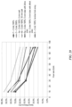
- Initial droplet studies show at least 65% to 70% of droplets ejected from the device are in the respirable range (e.g., 1 - 5 ⁇ m).
- the in-line droplet delivery device may include a combination reservoir/ejector mechanism module (e.g., drug delivery ampoule) that may be replaceable or disposable either on a periodic basis, e.g., a daily, weekly, monthly, as-needed, etc. basis, as may be suitable for a prescription or over-the-counter medication.
- the reservoir may be prefilled and stored in a pharmacy for dispensing to patients or filled at the pharmacy or elsewhere by using a suitable injection means such as a hollow injection syringe driven manually or driven by a micro-pump.
- the syringe may fill the reservoir by pumping fluid into or out of a rigid container or other collapsible or non-collapsible reservoir.
- such disposable/replaceable, combination reservoir/ejector mechanism module may minimize and prevent buildup of surface deposits or surface microbial contamination on the aperture plate, owing to its short in-use time.
- the ejector mechanism, reservoir, and housing/mouthpiece function to generate a plume with droplet diameters less than about 5 um.
- the reservoir and ejector mechanism modules are powered by electronics in the device housing and a reservoir which may carry sufficient drug for a single dose, just a few doses, or several hundred doses of medicament.
- the present disclosure also provides an in-line droplet delivery device that is altitude insensitive.
- the in-line droplet delivery device is configured so as to be insensitive to pressure differentials that may occur when the user travels from sea level to sub-sea levels and at high altitudes, e.g., while traveling in an airplane where pressure differentials may be as great as 4 psi.
- the in-line droplet delivery device may include a superhydrophobic filter, optionally in combination with a spiral vapor barrier, which provides for free exchange of air into and out of the reservoir, while blocking moisture or fluids from passing into the reservoir, thereby reducing or preventing fluid leakage or deposition on aperture plate surfaces.
- the devices of the disclosure eliminate the need for patient / device coordination by using a differential pressure sensor to initiate the piezoelectric ejector in response to the onset of inhalation.
- the device does not require manual triggering of medication delivery.
- the droplets from the devices of the disclosure are generated having little to no intrinsic velocity from the aerosol formation process and are inspired into the lungs solely by the user's incoming breath passing through the mouthpiece. The droplets will ride on entrained air providing improved deposition in the lung.
- the device when the drug ampoule is mated to the handheld base unit, electrical contact is made between the base containing the batteries and the ejector mechanism embedded in the drug reservoir.
- visual indications e.g., a horizontal series of three user visible LED lights, and audio indications via a small speaker within the handheld base unit may provide user notifications.
- the device may be, e.g., 2.0 -3.5 cm high, 5-7 cm wide, 10.5-12 cm long and may weight approximately 95 grams with an empty drug ampoule and with batteries inserted.
- the in-line droplet delivery device may be turned on and activated for use by inserting the drug ampoule into the base unit, opening the mouthpiece cover, and/or switching an on/off switch/slide bar.
- visual and/or audio indicators may be used to indicate the status of the device in this regard, e.g., on, off, stand-by, preparing, etc.
- one or more LED lights may turn green and/or flash green to indicate the device is ready for use.
- visual and/or audio indicators may be used to indicate the status of the drug ampoule, including the number of doses taken, the number of doses remaining, instructions for use, etc.
- LED visual screen may indicate a dose counter numerical display with the number of remaining doses in the reservoir.
- a differential pressure sensor within the housing detects inspiratory flow, e.g., by measuring the pressure drop across a Venturi plate at the back of the mouthpiece.
- a threshold pressure decline e.g. 8 slm
- the microprocessor activates the ejector mechanism, which in turn generates an ejected stream of droplets into the airflow of the device that the user inhales through the mouthpiece.
- audio and/or visual indicates may be used to indicate that dosing has been initiated, e.g., one or more LEDs may illuminate green.
- the microprocessor then deactivates the ejector at a designated time after initiation so as to achieve a desired administration dosage, e.g., 1-1.45 seconds.
- the device may provide visual and/or audio indicators to facilitate proper dosing, e.g., the device may emit a positive chime sound after the initiation of dosing, indicating to the user to begin holding their breath for a designated period of time, e.g., 10 seconds. During the breath hold period, e.g., the three green LEDs may blink. Additionally, there may be voice commands instructing the patient on proper times to exhale, inhale and hold their breath, with an audio indicator of a breath hold countdown.
- the in-line droplet delivery device may turned off and deactivated in any suitable manner, e.g., by closing the mouthpiece cover, switching an on/off switch/slide bar, timing out from non-use, removing the drug ampoule, etc.
- audio and/or visual indicators may prompt a user to deactivate the device, e.g., by flashing one or more red LED lights, providing voice commands to close the mouthpiece cover, etc.
- the in-line droplet delivery device may include an ejector mechanism closure system that seals the aperture plate when not in use to protect the integrity of the aperture plate and to minimize and prevent contamination and evaporation of the fluid within the reservoir.
- the device may include a mouthpiece cover that comprises a rubber plug that is sized and shaped to seal the exit side surface of the aperture plate when the cover is closed.
- the mouthpiece cover may trigger a slide to seal the exit side surface of the aperture plate when the cover is closed.
- the microprocessor may be configured to detect when the ejector mechanism closure, aperture plate seal, etc. is in place, and may thereafter deactivate the device.
- Droplet size is set by the diameter of the holes in the mesh which are formed with high accuracy.
- the holes in the aperture plate may range in size from 1 ⁇ m to 6 ⁇ m, from 2 ⁇ m to 5 ⁇ m, from 3 ⁇ m to 5 ⁇ m, from 3 ⁇ m to 4 ⁇ m, etc.
- Ejection rate, in droplets per second is generally fixed by the frequency of the aperture plate vibration, e.g., 108-kHz, which is actuated by the microprocessor. In certain embodiments, there is less than a 50-millisecond lag between the detection of the start of inhalation and full droplet generation.
- aspects of the device of the disclosure that allow for precise dosing of specific droplet sizes include the production of droplets within the respirable range early in the inhalation cycle, thereby minimizing the amount of drug product being deposited in the mouth or upper airways at the end of an inhalation.
- the design of the drug ampoule allows the aperture plate surface to be wetted and ready for ejection without user intervention, thus obviating the need for shaking and priming.
- the design of the drug ampoule vent configuration together with the ejector mechanism closure system limits fluid evaporation from the reservoir to less than 150 ⁇ L to 350 ⁇ L per month.
- the device may be constructed with materials currently used in FDA cleared devices. Standard manufacturing methods may be employed to minimize extractables.
- any suitable material may be used to form the housing of the droplet delivery device.
- the material should be selected such that it does not interact with the components of the device or the fluid to be ejected (e.g., drug or medicament components).
- polymeric materials suitable for use in pharmaceutical applications may be used including, e.g., gamma radiation compatible polymer materials such as polystyrene, polysulfone, polyurethane, phenolics, polycarbonate, polyimides, aromatic polyesters (PET, PETG), etc.
- the drug ampoule may be constructed of any suitable materials for the intended pharmaceutical use.
- the drug contacting portions may be made from material compatible with the desired active agent(s), e.g., albuterol sulfate and ipratropium bromide.
- the drug only contacts the inner side of the drug reservoir and the inner face of the aperture plate and piezoelectric element. Wires connecting the piezoelectric ejector mechanism to the batteries contained in the base unit may be embedded in the drug ampoule shell to avoid contact with the drug.
- the piezoelectric ejector may be attached to the drug reservoir by a flexible bushing. To the extent the bushing may contact the drug fluid, it may be, e.g., any suitable material known in the art for such purposes such as those used in piezoelectric nebulizers.
- the device mouthpiece may be removable, replaceable and may be cleaned. Similarly, the device housing and drug ampoule can be cleaned by wiping with a moist cloth.
- the mouthpiece may be interfaced with (and optionally removable and/or replaceable), integrated into, or part of the housing. In other embodiments, the mouthpiece may be interfaced with (and optionally removable and/or replaceable), integrated into, or part of the drug delivery ampoule.
- any suitable material may be used to form the mouthpiece of the droplet delivery device.
- the material should be selected such that it does not negatively interact with the components of the device or the fluid to be ejected (e.g., drug or medicament components).
- polymeric materials suitable for use in pharmaceutical applications may be used including, e.g., gamma radiation compatible polymer materials such as polystyrene, polysulfone, polyurethane, phenolics, polycarbonate, polyimides, aromatic polyesters (PET, PETG), etc.
- the mouthpiece may be removable, replaceable and sterilizable.
- the mouthpiece tube may be formed from sterilizable and transparent polymer compositions such as polycarbonate, polyethylene or polypropylene, as discussed herein.
- an electrostatic coating may be applied to the one or more portions of the housing, e.g., inner surfaces of the housing along the airflow pathway such as the mouthpiece, to aid in reducing deposition of ejected droplets during use due to electrostatic charge build-up.
- one or more portions of the housing may be formed from a charge-dissipative polymer.
- conductive fillers are commercially available and may be compounded into the more common polymers used in medical applications, for example, PEEK, polycarbonate, polyolefins (polypropylene or polyethylene), or styrenes such as polystyrene or acrylic-butadiene-styrene (ABS) copolymers.
- one or more portions of the housing e.g., inner surfaces of the housing along the airflow pathway such as the mouthpiece, may be coated with anti-microbial coatings, or may be coated with hydrophobic coatings to aid in reducing deposition of ejected droplets during use.
- Any suitable coatings known for such purposes may be used, e.g., polytetrafluoroethylene (Teflon).
- differential pressure sensor with adequate sensitivity to measure pressure changes obtained during standard inhalation cycles may be used, e.g., ⁇ 5 SLM, 10 SLM, 20 SLM, etc.
- pressure sensors from Sensirion, Inc., SDP31 or SDP32 are particularly well suited for these applications.
- the microprocessor in the device may be programmed to ensure exact timing and actuation of the ejector mechanism in accordance with desired parameters, e.g., based duration of piezoelectric activation to achieve desired dosages, etc.
- the device includes or interfaces with a memory (on the device, smartphone, App, computer, etc.) to record the date-time of each ejection event, as well as the user's inhalation flow rate during the dose inhalation to facilitate user monitoring, as well as drug ampoule usage monitoring.
- the microprocessor and memory can monitor doses administered and doses remaining in a particular drug ampoule.
- the drug ampoule may comprise components that include identifiable information
- the base unit may comprise components that may "read" the identifiable information to sense when a drug ampoule has been inserted into the base unit, e.g., based on a unique electrical resistance of each individual ampoule, an RFID chip, or other readable microchip (e.g., cryptoauthentication microchip). Dose counting and lockouts may also be preprogramed into the microprocessor.
- the signal generated by the pressure sensors provides a trigger for activation and actuation of the ejector mechanism to thereby generate droplets and delivery droplets at or during a peak period of a patient's inhalation (inspiratory) cycle and assures optimum deposition of the plume of droplets and delivery of the medication into the pulmonary airways of the user.
- the in-line droplet delivery device provides a reliable monitoring system that can date and time stamp actual deliver of medication, e.g., to benefit patients with asthma through self-monitoring or through involvement of care givers and family members.
- the ability of a parent to know the use of asthma medications in a child is obvious. Physicians who can access such information will be better equipped to help their patients with asthma and COPD. It is even possible to consider monitoring of the impact of environmental conditions in a patient population with asthma to help determine public policy.
- the in-line droplet delivery device of the disclosure may detect inspiratory airflow and record/store inspiratory airflow in a memory (on the device, smartphone, App, computer, etc.).
- a preset threshold e.g., 8-10 slm triggers delivery of medication over a defined period of time, e.g., 1-1.5 seconds. Inspiratory flow is sampled frequently until flow stops. The number of times that delivery is triggered is incorporated and displayed in the dose counter LED on the device. Blue tooth capabilities permit the wireless transmission of the data.
- Bluetooth communication in the device will communicate date, time and number of actuations per session to the user's smartphone.
- Software programing can provide charts, graphics, medication reminders and warnings to patients and whoever is granted permission to the data.
- the software application will be able to incorporate multiple medications that use the device of the disclosure (e.g. albuterol, inhaled steroid, etc.).
- the monitoring capability should lead to early detection of worsening asthma or COPD and early intervention that will reduce exacerbations.
- the worsening would be detected through the increased requirement for rescue medication. While there are often identifiable triggers to disease worsening, worsening may occur due to lack of adherence to maintenance medication. Prevention of exacerbations or early interventions can potentially have profound positive impacts on quality of life and health resource utilization.
- monitoring data may provide support for improvement in disease state and the possibility for reducing maintenance medications.
- the device of the disclosure can also provide directed instruction to users, including audio and visual indicators to facilitate proper use of the device and proper dosing. For instance, patients with COPD or asthma who need drug delivered to an inflamed and narrowed lower respiratory region are typically asked to inhale drug particles slowly and steadily followed by about ten seconds of holding their breath to allow sedimentation to occur. In a medical office these patients can be coached and encouraged to hold their breath after inhalation. However, outside of a medical care setting, improper use of an inhaler device often results.
- the device of the present disclosure is configured to dispense droplets during the correct part of the inhalation cycle, and can including instruction and/or coaching features to assist patients with proper device use, e.g., by instructing the holding of breath for the correct amount of time after inhalation.
- the device of the disclosure allows this dual functionality because it may both monitor air flow during the inhalation, and has internal sensors/controls which may detect the end of inhalation (based upon measured flow rate) and can cue the patient to hold their breath for a fixed duration after the inhalation ceases.
- a patient may be coached to hold their breath with an LED that is turned on at the end of inhalation and turned off after a defined period of time (i.e., desired time period of breath hold), e.g., 10 seconds.
- the LED may blink after inhalation, and continue blinking until the breath holding period has ended.
- the processing in the device detects the end of inhalation, turns on the LED (or causes blinking of the LED, etc.), waits the defined period of time, and then turns off the LED.
- the device can emit audio indications, e.g., one or more bursts of sound (e.g., a 50 millisecond pulse of 1000 Hz), verbal instructions to hold breath, verbal countdown, music, tune, melody, etc., at the end of inhalation to cue a patient to hold their breath for the during of the sound signals. If desired, the device may also vibrate during or upon conclusion of the breath holding period.
- audio indications e.g., one or more bursts of sound (e.g., a 50 millisecond pulse of 1000 Hz)
- verbal instructions to hold breath e.g., a 50 millisecond pulse of 1000 Hz
- verbal countdown e.g., a 50 millisecond pulse of 1000 Hz
- music, tune, melody e.g., a 50 millisecond pulse of 1000 Hz
- the device may also vibrate during or upon conclusion of the breath holding period.
- the device provides a combination of audio and visual methods (or sound, light and vibration) described above to communicate to the user when the breath holding period has begun and when it has ended. Or during the breath holding to show progress (e.g., a visual or audio countdown).
- the device of the disclosure may provide coaching to inhale longer, more deeply, etc.
- the average peak inspiratory flow during inhalation (or dosing) can be utilized to provide coaching. For example, a patient may hear a breath deeper command until they reach 90% of their average peak inspiratory flow as measured during inspiration (dosing) as stored on the device, phone or in the cloud.
- an image capture device including cameras, scanners, or other sensors without limitation, e.g . charge coupled device (CCD), may be provided to detect and measure the ejected aerosol plume.
- CCD charge coupled device
- detectors, LED, delta P transducer, CCD device all provide controlling signals to a microprocessor or controller in the device used for monitoring, sensing, measuring and controlling the ejection of a plume of droplets and reporting patient compliance, treatment times, dosage, and patient usage history, etc., via Bluetooth, for example.
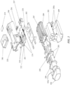
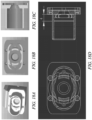
- FIGS. 1A and 1B illustrate an exemplary in-line droplet delivery device of the disclosure, with FIG. 1A showing the in-line droplet delivery device 100 having a mouthpiece cover 102 in the closed position, and FIG. 1B having a mouthpiece cover 102 in the open position.
- the droplet delivery device is configured in an in-line orientation in that the housing, its internal components, and various device components (e.g., the mouthpiece, air inlet flow element, etc.) are orientated in a substantially in-line or parallel configuration (e.g., along the airflow path) so as to form a small, hand-held device.
- various device components e.g., the mouthpiece, air inlet flow element, etc.
- the in-line droplet delivery device 100 includes a base unit 104 and a drug delivery ampoule 106. As illustrated in this embodiment, and discussed in further detail herein, the drug delivery ampoule 106 slides into the front of the base unit 104 via slides 112.
- mouthpiece cover 102 may include a push element 102a that facilitates insertion of drug delivery ampoule 106. Also illustrated are one or more airflow entrances or openings 110. By way of example, there may be airflow entrances on the opposite side of the device, multiple airflow entrances on the same side of the device, or a combination thereof (not shown).
- the in-line droplet delivery device 100 also includes mouthpiece 108 at the airflow exit side of the device.
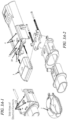
- FIG. 2 an exploded view of the exemplary in-line droplet delivery device of FIGS. 1A and 1B is shown, including internal components of the housing including a power/activation button 201; an electronics circuit board 202; a drug delivery ampoule 106 that comprises an ejector mechanism and reservoir (not shown); and a power source 203 (e.g., three AAA batteries, which may optionally be rechargeable) along with associated contacts 203a.
- the reservoir may be single-unit dose or multi-unit dose that may be replaceable, disposable or reusable.
- one or more pressure sensors 204 and optional spray sensors 205 are shown, including a pressure sensors 204 and optional spray sensors 205.
- the device may also include various electrical contacts 210 and 211 to facilitate activation of the device upon insertion of drug delivery ampoule 106 into the base unit.
- the device may include slides 212, posts 213, springs 214, and ampoule lock 215 to facilitate insertion of drug delivery ampoule 106 into the base unit.
- the components may be packaged in a housing, and generally oriented in an in-line configuration.
- the housing may be disposable or reusable, single-dose or multi-dose. Although various configurations to form the housing are within the scope of the disclosure, as illustrated in FIG. 2 , the housing may comprise a top cover 206, a bottom cover 207, and an inner housing 208.
- the housing may also include a power source housing or cover 209.
- the device may include audio and/or visual indications, e.g., to provide instructions and communications to a user.
- the device may include a speaker or audio chip (not shown), one or more LED lights 216, and LCD display 217 (interfaced with an LCD control board 218 and lens cover 219).
- the housing may be handheld and may be adapted for communication with other devices via a Bluetooth communication module or similar wireless communication module, e.g., for communication with a subject's smart phone, tablet or smart device (not shown).
- an air inlet flow element (not shown, see, e.g., FIGS. 5A-5C and FIGS. 11A -18D) may be positioned in the airflow at the airflow entrance of the housing and configured to facilitate non-turbulent (i.e., laminar and/or transitional) airflow across the exit side of aperture plate and to provide sufficient airflow to ensure that the ejected stream of droplets flows through the droplet delivery device during use.
- the air inlet flow element may be positioned within the mouthpiece. Aspects of the present embodiment further allows customizing the internal pressure resistance of the particle delivery device by allowing the placement of laminar flow elements having openings of different sizes and varying configurations to selectively increase or decrease internal pressure resistance, as will be explained in further detail herein.
- an exemplary method of insertion of an ampoule through to use and powering off of the device may be performed as follows:
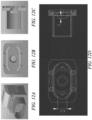
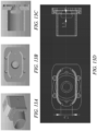
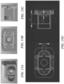
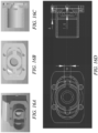
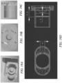
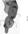
- FIGS. 3A-1 to FIG. 3C-3 a specific exemplary embodiment of a mode of operation of insertion of a drug ampoule and operation of a device is illustrated in FIGS. 3A-1 to FIG. 3C-3.
- a drug ampoule (1) when initially inserted and pushed onto the device slide guide (1a), the device door (2) is open, the ampoule slides and clicks into ampoule position 1.
- the seal on the aperture plate is open, the four electrical contacts on the device and ampoule make contact, and the system is powered ON, ready for breath actuation.
- the front two contacts (3) complete the circuit to actuate the piezoelectric element, while the rear two contacts (4) are used to provide specific information on the ampoule, such as ampoule ID, drug type, dosage, etc.
- ampoule position 1(A) is shown, in which the oval button (1b) locks the ampoule into place and the four electrical contacts, front (3) and rear (4) connect to complete the electric circuit.
- the electronic component that activates the ON/OFF button (1c) is pushed by the spring-loaded, slide mechanism (5).
- FIG. 3B-1 provides a bottom view of the spring-loaded slide mechanism (5) and the ON/OFF button (1c), in the ON mode.
- 3B-2 provides an exploded view (5a) of side brackets on the spring-loaded slide (5) and their position (5a- dash arrows) through slots (5b) on the device which make contact on the ampule (5c) to push the ampule forward when the device door is opened and activate the ON/OFF switch (1c) as it makes contact with the ON/OFF button (1d).
- the device ON/OFF button (1c) is activated by the slide (5) when the mouthpiece cover (2) is closed and pushes the ampule back to position 2, where the aperture plate seal is in the closed position and power is turned OFF to the device as pressure on the ON/OFF switch is released.
- FIG. 3C -1, 3C-2, and 3C-3 cross-sections of the device with the ampoule inserted are illustrated to better illustrate the ampoule slide mechanism and positioning of the ON/OFF switch.
- FIG. 3C -1 shows ampoule position 1, with the mouthpiece cover in the open position and the ON/OFF switch in the ON position.
- FIG. 3C- 2 shows ampoule position 2, with the mouthpiece cover in the closed position and the ON/OFF switch in the OFF position.
- FIG. 3C -3 shows ampoule position 2, with the mouthpiece cover in the open position and the ON/OFF switch in the OFF position.
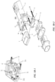
- FIGS. 4A and 4B illustrate an alternative in-line droplet delivery device of the disclosure, with FIG. 4A showing the in-line droplet delivery device 400 with a base unit 404 having a mouthpiece cover 402 in the closed position, and FIG. 4B with a base unit 404 having a mouthpiece cover 402 in the open position.
- the droplet delivery device is configured in an in-line orientation in that the housing, its internal components, and various device components (e.g., the mouthpiece, air inlet flow element, etc.) are orientated in a substantially in-line or parallel configuration (e.g., along the airflow path) so as to form a small, hand-held device.
- the in-line droplet delivery device 400 includes a base unit 404 and a drug delivery ampoule 406. As illustrated in this embodiment, and discussed in further detail herein, the drug delivery ampoule 406 slides into the front of the base unit 404.
- mouthpiece cover 402 may include aperture plate plug 412. Also illustrated are one or more airflow entrances or openings 410 in mouthpiece 408. By way of example, there may be airflow entrances on the opposite side of the device, multiple airflow entrances on the same side of the device, or a combination thereof (not shown).
- the in-line droplet delivery device 400 also includes mouthpiece 408 at the airflow exit side of the device.
- an exploded view of the exemplary in-line droplet delivery device of FIGS. 4A and 4B is shown, including internal components of the housing including an electronics circuit board 502; a drug delivery ampoule 406 that comprises top cover 430 having optional vents 431 and vapor barriers 432, an ejector mechanism 434, a drug reservoir 435, electrical contacts 436, and one or more sensor ports 437; and a power source 503 (e.g., three AAA batteries, which may optionally be rechargeable).
- the device may also include various electrical contacts 442 and sensor ports 444 to facilitate activation of the device upon insertion of drug delivery ampoule 406 into the base unit 404.
- the device may include resistors or chips 504 to facilitate insertion and detection of drug delivery ampoule 406 into the base unit 404.
- the reservoir may be single-unit dose or multi-unit dose that may be replaceable, disposable or reusable.
- the drug delivery ampoule may also comprise or be interfaced with a mouthpiece 408 and a mouthpiece cover 402.
- ejector mechanism 434 may be positioned in line with mouthpiece 408 and drug reservoir 435 such that the exit side of the aperture plate is perpendicular to the direction of airflow and the stream of droplets is ejected in parallel to the direction of airflow.
- the mouthpiece cover 402 may further include an aperture plate plug 412.
- the components may be packaged in a housing, and generally oriented in an in-line configuration.
- the housing may be disposable or reusable, single-dose or multi-dose. Although various configurations to form the housing are within the scope of the disclosure, as illustrated in FIG. 5 , the housing may comprise a top cover 506, a bottom cover 507, and an inner housing 508.
- the device may also include one or more ampoule release buttons 550, e.g., positioned on the side of the housing to facilitate release of the drug delivery ampoule 406 once inserted into the base unit 404.
- the device may include audio and/or visual indications, e.g., to provide instructions and communications to a user.
- the device may include a speaker or audio chip 520, one or more LED lights 516, and LCD display 517 (interfaced with an LCD control board 518 and lens cover 519).
- the housing may be handheld and may be adapted for communication with other devices via a Bluetooth communication module or similar wireless communication module, e.g., for communication with a subject's smart phone, tablet or smart device (not shown).
- a cross-section of an in-line device of FIGS. 4A and 4B is shown to illustrate an exemplary configuration of the interior of the drug reservoir 435 and its relation to ejector mechanism 434.
- drug reservoir 435 may be sized and shaped such that the volume of fluid held within the reservoir is funneled and directed to the ejection surface of the aperture plate during use. More particularly, as shown, the bottom surface of the drug reservoir may be sloped towards the ejector mechanism so as to facilitate flow of the fluid within the drug reservoir during use.
- such configurations may be particularly suited for device orientations wherein the ejector mechanism is oriented perpendicularly to the direction of airflow.
- the disclosure is not so limited, and various shapes, sizes and configurations of ampoule are envisioned as within the scope of the disclosure.
- FIG. 7 illustrates the base unit 404 of the embodiment of FIGS. 4A and 4B without the drug delivery ampoule inserted. Without the drug delivery ampoule inserted, tracks 440 for directing the ampoule into place, electrical contacts 442, and sensor port 444 are shown. Also shown is release button 450.
- FIGS. 8A and 8B illustrate a drug delivery ampoule 406 with mouthpiece cover 402 attached and in a closed position in front view ( FIG. 8A ) and back view ( FIG. 8B).
- FIG. 8B illustrates electrical contacts 436 and sensor port 437 of the ampoule, as well as protruding slides 452 to facilitate placement of the ampoule into tracks 440 during insertion.
- protruding slides 452 mate with tracks 440
- sensor port 437 mates with sensor port 444
- electrical contacts 436 mates with electrical contacts 442.
- the drug delivery ampoule is pushed into the base unit and locked into place with the protruding slides and tracks engaging one another.
- a pressure sensor located on the control board senses pressure changes within the device via the pressure sensing ports (e.g., within the mouthpiece).
- the base unit includes a second pressure sensing port and outside channel (not shown) to facilitate sensing of reference or ambient pressure.
- the drug reservoir and/or drug delivery ampoule may include various vents and/or vapor barriers to facilitate venting, etc.
- an exemplary reservoir or ampoule is shown which is configured so as to be insensitive to pressure differentials that may occur when the user travels from sea level to sub-sea levels and at high altitudes, e.g., while traveling in an airplane where pressure differentials may be as great as 4 psi.
- FIG. 9A shows a perspective view of an exemplary ampoule 900.
- FIGS 9B and 9C show exploded view of ampoule 900 from perspective top and bottom views.
- the ampoule 900 generally includes a top cover 901 and a bottom cover 902.
- the ampoule 900 may be configured to include one or more superhydrophobic filter(s) 904 covering one or more vents 906, and the fluid reservoir housing may include a spiral channel (or similarly shaped) vapor barrier 905, which provides for free exchange of air into and out of the fluid reservoir, while blocking moisture or fluids from passing into the reservoir, thereby reducing or preventing fluid leakage or deposition on aperture plate surfaces.
- one or more O-rings 903, or similar sealing mechanism may be used to form a seal between the top cover 901 and the bottom cover 902 in connection with the vapor barrier 905.
- the superhydrophobic filter and vent may generally allow for the venting of air and equilibration of air pressure within the fluid reservoir, while maintaining a sterile environment within the fluid reservoir.
- the spiral channel vapor barrier will generally prevent the transfer of moisture to and from the fluid reservoir (e.g., through the vent opening).
- the in-line droplet delivery devices of the disclosure may include an air inlet flow element (see, e.g., FIGS. 10A -10C and 12A-19D) which may be positioned in the airflow at the airflow entrance of the device and configured to facilitate non-turbulent (i.e., laminar and/or transitional) airflow across the exit side of aperture plate and to provide sufficient airflow to ensure that the ejected stream of droplets flows through the droplet delivery device during use.
- the air inlet flow element may be positioned within the mouthpiece. Aspects of the present embodiment further allows customizing the internal pressure resistance of the particle delivery device by allowing the placement of laminar flow elements having openings of different sizes and varying configurations to selectively increase or decrease internal pressure resistance, as will be explained in further detail herein.
- the device may include an air inlet flow element may be positioned in the airflow at the airflow entrance of the device and configured to facilitate non-turbulent (i.e., laminar and/or transitional) airflow across the exit side of aperture plate and to provide sufficient airflow to ensure that the ejected stream of droplets flows through the droplet delivery device during use.
- the air inlet flow element may be positioned within the mouthpiece.
- the air inlet flow element allows for customization of internal device pressure resistance by designing openings of different sizes and varying configurations to selectively increase or decrease internal pressure resistance.
- the air inlet flow element may be positioned behind the exit side of the aperture plate along the direction of airflow, or in-line or in front of the exit side of the aperture plate along the direction of airflow.
- the air inlet flow element comprises one or more openings formed there through and configured to increase or decrease internal pressure resistance within the droplet delivery device during use.
- the air inlet flow element comprises an array of one or openings.
- the air inlet flow element comprises one or more baffles, e.g., wherein the one or more baffles comprise one or more airflow openings.
- the air inlet flow element is designed and configured in order to provide an optimum airway resistance for achieving peak inspirational flows that are required for deep inhalation which promotes delivery of ejected droplets deep into the pulmonary airways.
- Air inlet flow elements also function to promote non-turbulent flow across the aerosol plume exit port, which also serves to stabilize airflow repeatability, stability and insures an optimal precision in the delivered dose.
- the size, number, shape and orientation of flow restrictions (e.g., openings, holes, flow blocks, etc.) in the air inlet flow element of the disclosure may be configured to provide a desired pressure drop within the in-line droplet delivery device. In certain embodiments, it may be generally desirable to provide a pressure drop that is not so large as to strongly affect a user's breathing or perception of breathing.
- the use of air inlet flow elements having differently configured, sized, and shaped flow restrictions (e.g., openings, holes, flow blocks, etc.), or the use of adjustable apertures may be required in order to accommodate the differences among the lungs and associated inspiratory flow rates of young and old, small and large, and various pulmonary disease states.
- the aperture is adjustable by the patient (perhaps by having a slotted ring that can be rotated)
- a method may be provided to read the aperture hole setting and lock that position to avoid inadvertent changes of the aperture hole size, hence the flow measurement.
- pressure sensing is an accurate method for flow measurement
- other embodiments may use, e.g., hot wires or thermistor types of flow rate measurement methods which lose heat at a rate proportional to flow rate, moving blades (turbine flow meter technology) or by using a spring-loaded plate, without limitation of example.
- FIGS. 10A -10C illustrate certain exemplary air inlet flow elements of the disclosure.
- FIGS. 10A -10C also illustrate the position of pressure sensors, the mouthpiece, and air channels for reference pressure sensing.
- the disclosure is not so limited, and other configurations including those described herein are contemplated as within the scope of the disclosure.
- the air inlet flow elements of FIGS. 10A -10C are particularly suitable for use with the in-line droplet delivery devices of FIGS. 1A -1B.
- FIG. 10A illustrates a cross-section of a partial in-line droplet delivery device 1000 of the disclosure including a mouthpiece cover 1001, a mouthpiece 1002, a drug delivery ampoule 1003 comprising a drug reservoir 1004 and an ejector mechanism 1005.
- the droplet delivery device includes an air inlet flow element 1006 having an array of holes 1006a at the air entrance of the mouthpiece 1002.
- a pressure sensor port 1007 which may be used to sense a change in pressure within the mouthpiece.
- FIG. 10B a front view of the device 1000 is illustrated, wherein a second pressure sensor port 1008 is shown to provide for sensing of a reference or ambient pressure.
- FIG. 10C illustrates a partial exploded view including mouthpiece 1002 and inner housing 1011.
- mouthpiece 1002 includes air intake flow element 1006 with an array of holes 1006a, and pressure sensor port 1007.
- mouthpiece 1002 may include an ejection port 1114 positioned, e.g., on the top surface of the mouthpiece so as to align with the ejector mechanism to allow for ejection of the stream of droplets into the airflow of the device during use.
- Other sensor ports 1115 may be positioned as desired along the mouthpiece to allow for desired sensor function, e.g., spray detection.
- the mouthpiece may also include positioning baffle 1116 that interfaces with the base unit upon insertion.
- Inner housing 1011 includes pressure sensor board 1009 and outside channel 1010 for facilitating sensing of reference or ambient pressure.
- the inner housing further includes a first pressure sensing port 1112 to facilitate sensing of pressure changes within the device (e.g., within the mouthpiece or housing), and a second pressure sensing port 1113 to facilitate sensing of reference or ambient pressure.
- FIG. 11A illustrates differential pressure as a function of flow rates through exemplary air inlet flow elements similar to that of FIGS. 10A -10C as a function of number of holes (29 holes, 23 holes, 17 holes).
- FIG. 11B the flow rate verses differential pressure as a function of hole size is shown to have a liner relationship, when flow rate is plotted as a function of the square root of differential pressure. The number of holes is held constant at 17 holes.
- a particular non-limiting exemplary air inlet flow element may 29 holes, each 1.9 mm in diameter.
- the air inlet flow element may have hole diameters ranging from, e.g., 0.1 mm in diameter to diameters equal to the cross sectional diameter of the air inlet tube (e.g., 0.5 mm, 1 mm, 1.5 mm, 2 mm, 2.5 mm, 3 mm, 3.5 mm, 4 mm, 4.5 mm, 5 mm, 5.5 mm, 6 mm, 6.5 mm, etc.), and number of holes may range from 1 to the number of holes, for example, to achieve the desire air flow resistance, e.g., 2, 3, 4, 5, 6, 7, 8, 9, 10, 15, 20, 25, 29, 30, 60, 90, 100, 150, etc.
- FIGS. 12A -19D illustrate alternative embodiments of air inlet flow elements of the disclosure.
- FIGS. 12A -19D also illustrate exemplary positioning of air inlet flow elements within the airflow of a device, within the mouthpiece, as well as the interfacing of a mouthpiece including an air inlet flow element to an drug delivery ampoule.
- FIG. 12A shows an exemplary drug delivery ampoule with a mouthpiece interfaced at the airflow exit side of the device.
- the mouthpiece includes two airflow entrances on the sides, but no internal air inlet flow elements to provide resistance to airflow.
- FIG. 12B shows a front cross-section and 12C shows a side cross-section, with FIG. 12D showing the same views with exemplary dimensions.
- FIGS. 13A and 14A show similarly configured mouthpieces with two airflow entrances on the sides, but no internal air inlet flow elements to provide resistance to airflow. Again, FIGS. 13B and 14B show a front cross-section and 13C and 14C show a side cross-section, with FIGS.
- FIG. 12 has openings that are 6.6 mm long and 2 mm high
- the embodiment of FIG. 13 has openings that are 7.9 mm long and 2.5 mm high
- the embodiment of FIG. 14 has openings that are 8.1 mm long and 3 mm high.
- the disclosure is not limited to these specific dimensions, and varied dimensions and numbers of air inflow openings are envisions as within the scope of the disclosure.
- FIG. 15A shows an exemplary drug delivery ampoule with a mouthpiece interfaced at the airflow exit side of the device.
- the mouthpiece includes two airflow entrances on the exterior sides of the mouthpiece, and two interior baffles with additional airflow entrances to provide resistance and modeling of airflow.
- FIG. 15B shows a front cross-section and 15C shows a side cross-section, with FIG. 15D showing the same views with exemplary dimensions.
- FIG. 16A shows a similarly configured mouthpiece that includes two airflow entrances on the exterior sides of the mouthpiece, and two interior baffles with additional airflow entrances to provide resistance and modeling of airflow. However, the interior baffles of FIG. 16A are larger (10 mm in height) than that of FIG. 15A (5 mm in height).
- FIG. 16B shows a front cross-section and 16C shows a side cross-section, with FIG. 16D showing the same views with exemplary dimensions.
- FIG. 17A shows an exemplary drug delivery ampoule with a mouthpiece interfaced at the airflow exit side of the device.
- the mouthpiece includes two airflow entrances on the exterior sides of the mouthpiece, and a substantially concentric baffle (two arcs that form a circle with the top and bottom of the mouthpiece) with two additional airflow entrances to provide resistance and modeling of airflow.
- FIG. 17B shows a front cross-section and 17C shows a side cross-section, with FIG. 17D showing the same views with exemplary dimensions.
- FIG. 18A shows a similarly configured mouthpiece with a substantially concentric interior baffle, but the interior baffle includes four airflow entrances to provide resistance and modeling of airflow.
- FIG. 18B shows a front cross-section and 18C shows a side cross-section, with FIG. 18D showing the same views with exemplary dimensions.
- FIG. 19A shows an exemplary drug delivery ampoule with a mouthpiece interfaced at the airflow exit side of the device.
- the mouthpiece includes two airflow entrances on the exterior sides of the mouthpiece, and a substantially concentric baffle with two additional airflow entrances to provide resistance and modeling of airflow.
- the interior area of the mouthpiece between the concentric baffle and the wall of the mouthpiece includes an array element positioned above the airflow entrances to provide additional resistance and modeling to airflow.
- the array element is positioned in a parallel arrangement with the direction of airflow.
- FIG. 19B shows a front cross-section
- 19C shows a side cross-section
- FIG. 19D showing the same views with exemplary dimensions.
- inner air inlet flow elements generally improve spray efficiency for exemplary fluid solutions (deionized water and albuterol solution.
- exemplary fluid solutions deionized water and albuterol solution.
- inner air inlet flow elements increase spray efficiency from 47% to 66%, and orienting interior airflow entrances away from ejection streams improves spray efficiency to 80% or more.
- the mouthpiece and drug reservoir are a single unit and can be weighted before ejection (W1), after ejection (W2) and after drying (W3) the mouthpiece to measure the percentage of ejected drug that leaves the mouthpiece for delivery to a user.
- Spray efficiency (W1-W2)/(W1-W3)
- the in-line device may be configured to protect the surface of the aperture plate, to minimize evaporation losses, and to minimize contamination while the device is closed and not in use.
- the surface of the aperture plate of the ejector mechanism may be closed/sealed against the housing or the mouthpiece cover.
- the reservoir/ampoule includes an O-ring or gasket to facilitate the seal of the surface of the aperture plate of the ejector mechanism
- the sliding of the reservoir/ampoule between the open and closed position may, in certain aspects, create friction which needs to be overcome by a compression spring during opening and closing.
- friction between the ampoule O-ring and the device housing may be reduced by applying a compressive force between the ampoule and the device housing in the last few millimeters as the ampoule is closed.
- a compressive force between the ampoule and the device housing in the last few millimeters as the ampoule is closed.
- higher friction is limited to the first few millimeters during opening, when the compression spring is providing the highest force; and during the last few millimeters of closing when the ampoule door is almost closed and force on the door is easiest for the user to apply.
- Force applied as the door is almost closed also creates minimal reaction forces at the door's hinge, improving robustness of the device. Applying pressure to the O-ring over a shorter distance also reduces wear on the O-ring (or gasket).
- applying a compressive sealing force during the last few millimeters of ampoule motion to the closed position can be accomplished by utilizing a ramp on either the ampoule or device side of the ampoule track which engages a budge on the opposite face (device for ampoule or ampoule for device) as the ampoule approaches the closed position.
- This can also be a pair of ramps which engage as the ampoule approaches the closed position.
- the point(s) of contact between the ampoule and device should be in alignment with the center of pressure of the O-ring to create a uniform sealing pressure. Note that to achieve enough compression for good sealing, the total vertical motion created by the ramp only needs to be in the range of 0.1 mm.
- a flexible compressive element can apply a downward force the rises as the ampoule approaches the closed position.
- this could be the ramp intersecting a flexible, rubber-like, material or a metallic or plastic spring, including a cantilever (leaf) spring that the ramp encounters as it arrives at the closed position of the ampule.
- the compressive force applied to the O-ring does not have to be large, but sufficient for the compliant O-ring to seal against the surface roughness of the device surface. In certain embodiments, a more compliant material will require less compressive force to seal.
- the O-ring can be made from a slippery material such as teflon-coated or teflon-encapsulated material to reduce the sliding friction of the ampule. Similarly, sealing may be done by a lip seal at the face.
- FIGS. 21A -21C illustrate exemplary embodiments showing a ramp structure on the ampoule lip that presses the ampoule down and compresses the O-ring while in the "closed" position. Note, as illustrated the size of the ramp is greatly exaggerated. In one embodiment, the ramp may be about 0.1 to 0.2 mm high.
- FIG. 21A shows an end view showing ampule with lips that are engaged in track that is part of body of device.
- FIG. 21B shows how an ampoule moves from closed to open position. Mouthpiece and user to the right.
- FIG. 21C illustrates a side view of an ampoule in track with a ramp on a lip to force a aperture plate seal, showing a closed and open position.
- mouthpiece cover 2100 may include aperture plate plug 2102 that is specifically sized and shaped so as to form a mating seal against the surface of the aperture plate 2104 when the cover is closed.
- the aperture plate plug 2102 may have a stepped shape such that the plug forms a seal against the surface of the housing around the aperture plate without putting direct pressure on the surface of the aperture plate.
- the reservoir/cartridge module may include components that may carry information read by the housing electronics including key parameters such as ejector mechanism functionality, drug identification, and information pertaining to patient dosing intervals. Some information may be added to the module at the factory, and some may be added at the pharmacy. In certain embodiments, information placed by the factory may be protected from modification by the pharmacy.
- the module information may be carried as a printed barcode or physical barcode encoded into the module geometry (such as light transmitting holes on a flange which are read by sensors on the housing). Information may also be carried by a programmable or non-programmable microchip on the module which communicates to the electronics in the housing.
- module programming at the factory or pharmacy may include a drug code which may be read by the device, communicated via Bluetooth to an associated user smartphone and then verified as correct for the user.
- the smartphone might be prompted to lock out operation of the device, thus providing a measure of user safety and security not possible with passive inhaler devices.
- the device electronics can restrict use to a limited time period (perhaps a day, or weeks or months) to avoid issues related to drug aging or build-up of contamination or particulates within the device housing.
- the in-line droplet delivery device may further include various sensors and detectors to facilitate device activation, spray verification, patient compliance, diagnostic mechanisms, or as part of a larger network for data storage, big data analytics and for interacting and interconnected devices used for subject care and treatment, as described further herein.
- the housing may include an LED assembly on a surface thereof to indicate various status notifications, e.g., ON/READY, ERROR, etc.
- the airflow exit of the housing of the droplet delivery device through which the ejected plume of droplets exit as they are inhaled into a subject's airways may be configured and have, without limitation, a cross sectional shape of a circle, oval, rectangular, hexagonal or other shape, while the shape of the length of the tube, again without limitation, may be straight, curved or have a Venturi-type shape.
- a mini fan or centrifugal blower may be located at the air inlet side of the laminar flow element or internally of the housing within the airsteam.
- the mini fan generally may provide additional airflow and pressure to the output of the plume. For patients with low pulmonary output, this additional airplume may ensure that the plume of droplets is pushed through the device into the patient's airway. In certain implementations, this additional source of airflow ensures that the plume exit port is swept clean of the droplets and also provides mechanism for spreading the particle plume into an airflow which creates greater separation between droplets.
- the airflow provided by the mini fan may also act as a carrier gas, ensuring adequate dose dilution and delivery.
- the internal pressure resistance of the in-line droplet delivery device may be customized to an individual user or user group by modifying the mouthpiece tube design to include various configurations of air aperture grids or openings, thereby increasing or decreasing resistance to airflow through the device as the user inhales. For instance, different air entrance aperture sizes and numbers may be used to achieve different resistance values, and thereby different internal device pressure values. This feature provides a mechanism to easily and quickly adapt and customize the airway resistance of the particle delivery device to the individual patient's state of health or condition.
- the in-line droplet delivery devices provide for various automation, monitoring and diagnostic functions.
- device actuation may be provided by way of automatic subject breath actuation.
- the device may provide automatic spray verification, to ensure that the device has generated the proper particle generation and provided to proper dosing to the subject.
- the particle delivery device may be provided with one or more sensors to facilitate such functionality.
- an airflow sensor located in the mouthpiece may measure inspiratory and expiratory flow rates. This sensor is placed so that it does not interfere with drug delivery or become a site for collection of residue or promote bacterial growth or contamination.
- a differential (or gage) pressure sensor downplume of a flow restrictor (e.g., air inlet flow element) measures airflow based upon the pressure differential between the inside of the mouthpiece relative to the outside air pressure. During inhalation (inspiratory flow) the mouthpiece pressure will be lower than the ambient pressure and during exhalation (expiratory flow) the mouthpiece pressure will be greater than the ambient pressure.
- the magnitude of the pressure differential during an inspiratory cycle is a measure of the magnitude of airflow and airway resistance at the air inlet end of the delivery tube.
- Bluetooth connectivity facilitates implementation of various software or App's which may provide and facilitate patient training on the use of the device.
- a major obstacle to effective inhaler drug therapy has been either poor patient adherence to prescribed aerosol therapy or errors in the use of an inhaler device.
- the patient may be challenged to reach a goal of total inspiratory volume that was previously established and recorded on the smartphone during a training session in a doctor's office.
- Bluetooth connectivity further facilitates patient adherence to prescribed drug therapy and promotes compliance by providing a means of storing and archiving compliance information, or diagnostic data (either on the smartphone or cloud or other large network of data storage) that may be used for patient care and treatment.
- the droplet delivery device may provide automatic spray verification via LED and photodetector mechanisms.
- an infra-red transmitter e.g. , IR LED, or UV LED ⁇ 280 nm LED
- infra-red or UV (UV with ⁇ 280nm cutoff) photodetector may be mounted along the droplet ejection side of the device to transmit an infra-red or UV beam or pulse, which detects the plume of droplets and thereby may be used for spray detection and verification.
- the IR or UV signal interacts with the aerosol plume and can be used to verify that a plume of droplets has been ejected as well as provide a measure of the corresponding ejected dose of medicament.
- Examples include but not limited to, infrared 850 nm emitters with narrow viewing angles of either, 8, 10 and 12-degrees, (MTE2087 series) or 275 nm UV LED with a GaN photodetector for aerosol plume verification in the solar blind region of the spectra.
- the sub 280 nm LEDs e.g. 260 nm LEDs
- e the molar absorptivity coefficient (or molar extinction coefficient) which is a constant that is associated with a specific compound or formulation
- L is the path length or distance between LED emitter and photodetector
- c the concentration of the solution.
- spray verification and dose verification can be monitored by measuring the transmission of 850 nM to 950 nM light across the spray in a region where the droplets are not variably diluted with different inhalation flow rates.
- the average and alternating signals from the detector may be measured to calibrate and confirm the optical path (average signal) and detect the spray (alternating signal).
- the alternating signal can be measured by a 100 Hz low-pass filter between the detector and analog converter, sampling the signal 100 to 500 times a second, calculating the average and the range (maximum minus minimum) over 100 mS periods, and comparing these values to preset values to confirm proper operation and whether there was spray or not.
- This method has the strong advantages of: low power consumption (less than 1 ma to the emitter); unaffected by stray light (visible light blocking on the detector); relatively resistant to digital noise or the 100 kHz piezo drive by the 100 Hz low-pass filter; the average signal level can be used to adjust the optical path for attenuation caused by drug deposits on the LED or detector; and simple hardware with a positive signal that is robustly measured.
- This system also allows simple regulation of the optical signal strength by increasing power to the emitter should the average signal level decrease. Practically, this means using pulse width modulation of emitter current to regulate average emitter power.
- the pulses should be at a high rate, e.g., 100 kHz, so that this noise can be removed by the 100 Hz low pass filter.
- Nominal operation might use a 10% duty cycle of 10 mA to achieve and average current of 1 mA.
- This system would have the ability to increase the average current to 10 mA and correct for up to a factor of 10 attenuation by drug deposits.
- the average signal output is 2 volts and the peak to peak value of the alternating component is 4 mV without spray and 40 mV during spray.
- the resistor sizing here is for continuous running of the emitter and not PWM.
- the particle delivery device may be used in connection with or integrated with breathing assist devices such as a mechanical ventilator or portable Continuous Positive Airway Pressure (CPAP) machine, to provide in-line dosing of therapeutic agents with the breathing assistance airflow.
- breathing assist devices such as a mechanical ventilator or portable Continuous Positive Airway Pressure (CPAP) machine, to provide in-line dosing of therapeutic agents with the breathing assistance airflow.
- CPAP Continuous Positive Airway Pressure
- VAP ventilator-assisted pneumonia
- Tobramycin administration through the pulmonary route is generally regarded as superior to intravenous administration for treating VAP, with nebulizers being typically used to deliver the antibiotics through generation of a continuous plume of droplets into the ventilator airflow.
- the main benefit of inhaled versus oral or intravenous administered antibiotics is the ability to deliver a higher concentration of the antibiotic directly into the lungs.
- continuous generation of nebulizer mist provides imprecise dosing that cannot be verified between inhalation and exhalation cycles.
- an in-line droplet delivery device is placed in-line with a ventilator, (for example a GE Carescape R860).
- the in-line droplet delivery device generates a plume of droplets as described herein, which includes a therapeutic agent such as tobramycin, which enters into the ventilator airplume near to the patient end of the endotracheal tube.
- the ventilator supplies a plume of inhalation air and removes a plume of exhalation air in separate tubes that merge to a single endotracheal tube close to the patient to minimize mixing of inhalations and exhalations and dead volume.
- the in-line droplet delivery device may be placed close to the patient end of the endotracheal tube in order to minimize loss of droplets that may stick to the tube sidewall.
- the patient end of the endotracheal tube is placed in a patient's throat and held in place with a balloon near the end of the tube.
- Actuation of the in-line droplet delivery device is initiated at the start of an inhalation cycle.
- the in-line droplet delivery device can be battery powered and self-initiating breath actuated or connected to electronics that are part of the ventilator.
- the system may be configured so that dosing frequency and duration may be set either within the ventilator or the device.
- plume generation timing and duration can be determined by the device or initiated by the ventilator.
- the device may be programmed to dispense for half a second once every ten breaths on a continuous basis or perhaps once a minute.
- An in-line droplet delivery device may operate in a standalone manner or communicate the timing of dispenses and flowrates to the ventilator by a direct electrical connection or via Bluetooth or a similar wireless protocol.
- Another aspect of the disclosure provides a system which may also be used with conventional portable CPAP machines to deliver therapeutic agents, e.g., where continuous or periodic dosing during the course of the night is valuable.
- the in-line droplet delivery devices of the disclosure many be used in connection with a portable CPAP machine to prevent and treat cardiac events during sleep.
- CPAP machines use a mask to supply positive air pressure to a patient while sleeping.
- Applications of the in-line droplet delivery devices in conjunction with CPAP machines may provide an efficient method for continuous dosing of therapeutic agents such as antibiotics, cardiac medications, etc., for outpatient treatment of diseases, conditions, or disorders, such as pneumonia, atrial fibrillation, myocardial infarction, or any disease, condition, or disorder where continuous or periodic nighttime delivery of a medicine is desired.
- SA sleep apnea
- cardiac failure or "heart attacks” are associated with sleep apnea. This association is thought to be due to both the stress on the heart related to low oxygen levels and the increased stress on the heart as the body requires increased blood pressure and cardiac output from the heart. Additionally, there is increased risk of sleep apnea in older and overweight adults. Thus those with SA have a higher risk of heart attacks than the general population because the SA stresses the heart and because the risk factors associated with SA are very similar to the risk factors for heart attacks.
- beta blockers such as Metoprolol can lessen atrial fibrillation and the effects of myocardial infarction to sufficient extent as to prevent death in such an episode.
- a cardiac event may be detected by conventionally available means to detect and evaluate cardiac condition. These include heart rate monitors (such as electrical sensors held in place by an elastic band across the chest or optical monitoring at the earlobe, finger or wrist), automated blood pressure cuffs, or blood-oxygen saturation monitors on the finger or ear).
- heart rate monitors such as electrical sensors held in place by an elastic band across the chest or optical monitoring at the earlobe, finger or wrist
- automated blood pressure cuffs or blood-oxygen saturation monitors on the finger or ear.
- a specific dose of appropriate drug is administered by a particle delivery device of the disclosure via the CPAP tube or mask so that the drug is inhaled and carried to the blood plume via deep inhalation into the lung.
- Pulmonary administration is optimized both by the generation of droplets less than 5 microns in size and delivery of the droplets at the beginning of an inhalation cycle.
- an in-line droplet delivery device of the disclosure may be used with a CPAP machine to assist with cardiac events during sleeping.
- the patient may use a CPAP machine during sleep with a CPAP mask in place, wherein pressurized air is delivered to the mask by the CPAP machine.
- Cardiac condition may be monitored by optical measurement of the heartbeat either at finger, toe, ear lobe or the wrist.
- the in-line droplet delivery device may be placed in-line with the tube between the CPAP machine and the CPAP mask, or alternative may be placed at the airflow entrance of CPAP mask. Breathing is monitored by airflow measurement in the tube from the CPAP machine to the CPAP mask.
- Airflow rate and direction can be measured by measuring the pressure on either side of a screen which adds a slight amount of airflow restriction. Typically there will be continuous positive airflow which increases in flow rate at inspiration.
- a controller detects abnormal cardiac condition such as an increase in atrial fibrillation and triggers ejection of droplets of an anti-arrhythmic drug at the start of an inhalation cycle as detected by airflow in the CPAP supply tube.
- Information may be recorded and stored in a patient's smartphone, and various alerts may be sounded if a cardiac event is detected (e.g., transmitted via Bluetooth or other wireless communication methodology), if desired. Further, the patient's condition and drug dispenses may be monitored via a smartphone app, providing the patient and his medical provider with an accurate record of the patient's condition.
- DDU Delivered Dosage Uniformity testing was performed to measure the amount of drug discharged from the mouthpiece of the MDI and compare that to the specified target delivered dose (TDD).
- Testing was performed on equipment like that described in USP Unit Spray ⁇ 601> sampling apparatus. Testing was carried out under optimized conditions of air flow rate and total air volume (drawn through the device) during the test. The volume of collection was set to not exceed 2L at a constant flow rate of 28.3 SLPM. The total air volume was determined as 1.42L based on the device being activated for 3 seconds at a constant flow rate of 28.3 SLPM.
- USP ⁇ 601> recommends an air flow rate of 28.3 liters per minute (LPM) for testing delivered-dose uniformity. With the vacuum pump running, the air flow was set to 28.3 SLPM by adjusting the flow control valve and the timer was set to 3 seconds.
- LPM liters per minute
- the device was placed on a Model XS204 Mettler-Toledo Scale and weighed. The device was placed into the sampling apparatus. The button was pressed to activate the solenoid. The airflow of 28.3 SLPM was passed through the mouthpiece for 3 seconds. A three second duration was sufficient to ensure that the dose was completely discharged. The device was then removed from the mouthpiece adapter and weighed. The difference in weight represented the dose delivered from the device.
- Table 1 A summary of the spray content uniformity testing for 10 unique drug cartridges is provided in Table 1.
- the primary purpose of this test is to ensure the spray content uniformity within the same container and among multiple containers.
- testing was performed at the maximum level of drug fill (3.0 ml) and at the minimum level of drug fill (0.45 ml).
- the maximum level of drug fill represents a new cartridge that has not been used by the patient.
- the minimum level of drug fill represents a cartridge that has been used by the patient and has only 10 doses of drug remaining. The drug was dispensed over 1.5 seconds.
- Delivered Dosage Uniformity (DDU) testing was performed to measure the amount of drug discharged from the mouthpiece of an exemplary device of the disclosure, and was compared to the specified target delivered dose (TDD).
- the target dose for the device was 10.5 ⁇ L.
- Exemplary devices of the disclosure were evaluated using Albuterol sulfate at a concentration of 9,818 ug/ml, which is equivalent to 8,817ug/ml of Albuterol.
- the devices were tested in triplicate trials for each drug cartridge.
- the comparative device was tested with three (3) units that were tested singly.
- First testing involved single actuation content, which measured drug delivery per actuation for the device of the disclosure.
- Each of the three (3) cartridges were tested thirty (30) times and results were analyzed by HPLC.
- the cascade impactor trials involved triplicate testing for each cartridge and the comparative device for a total of twelve (12) trials. Cascade impactors were chilled to 4°C prior to testing and the device was actuated into the cascade impactors in the 4°C chilled environment before extracting the samples.
- the single actuation content tests involved testing three (3) cartridges a total of thirty (30) times each into the single actuation apparatus, which consists of a vacuum tube with a 47mm filter to collect drug delivery per actuation. The filter was then analyzed by HPLC to measure total drug content.
- For cascade impactor tests a total of three (3) cartridges and one (1) predicate device were tested in triplicate, 0.600 ml albuterol sulfate ampule containing a concentration of 9,818ug/ml albuterol sulfate was added to each cartridge for the testing.
- inhaler test samples were collected using an Anderson Cascade Impactor (ACI) sampling at a constant 28.3 lpm during the entirety of each test.
- the Anderson Cascade Impactor is an FDA approved device that can be used to determine the coarse particle mass, coarse particle fraction, respirable particle mass, respirable particle fraction, fine particle mass, and fine particle fraction of test aerosols.
- ACI data can also be used to calculate the Mass Median Aerodynamic Diameter (MMAD) and Geometric Standard Deviation (GSD) of the aerosol size distribution.
- MMAD Mass Median Aerodynamic Diameter
- GSD Geometric Standard Deviation
Landscapes
- Health & Medical Sciences (AREA)
- Engineering & Computer Science (AREA)
- Life Sciences & Earth Sciences (AREA)
- Anesthesiology (AREA)
- General Health & Medical Sciences (AREA)
- Heart & Thoracic Surgery (AREA)
- Hematology (AREA)
- Animal Behavior & Ethology (AREA)
- Veterinary Medicine (AREA)
- Public Health (AREA)
- Biomedical Technology (AREA)
- Pulmonology (AREA)
- Bioinformatics & Cheminformatics (AREA)
- Biophysics (AREA)
- Emergency Medicine (AREA)
- Medicinal Preparation (AREA)
- Pharmaceuticals Containing Other Organic And Inorganic Compounds (AREA)
- Acyclic And Carbocyclic Compounds In Medicinal Compositions (AREA)
Applications Claiming Priority (5)
| Application Number | Priority Date | Filing Date | Title |
|---|---|---|---|
| US201762568057P | 2017-10-04 | 2017-10-04 | |
| US201762575165P | 2017-10-20 | 2017-10-20 | |
| US201862622022P | 2018-01-25 | 2018-01-25 | |
| US201862732455P | 2018-09-17 | 2018-09-17 | |
| PCT/US2018/054417 WO2019071008A1 (en) | 2017-10-04 | 2018-10-04 | ELECTRONIC DEVICE FOR DELIVERY OF LINEAR SHAPE ADMINISTRATION OPERATED BY BREATHING AND METHODS OF USE |
Publications (4)
| Publication Number | Publication Date |
|---|---|
| EP3691728A1 EP3691728A1 (en) | 2020-08-12 |
| EP3691728A4 EP3691728A4 (en) | 2021-06-30 |
| EP3691728C0 EP3691728C0 (en) | 2024-05-22 |
| EP3691728B1 true EP3691728B1 (en) | 2024-05-22 |
Family
ID=65994985
Family Applications (1)
| Application Number | Title | Priority Date | Filing Date |
|---|---|---|---|
| EP18865088.1A Active EP3691728B1 (en) | 2017-10-04 | 2018-10-04 | Electronic breath actuated in-line droplet delivery device |
Country Status (6)
| Country | Link |
|---|---|
| US (2) | US11738158B2 (cg-RX-API-DMAC7.html) |
| EP (1) | EP3691728B1 (cg-RX-API-DMAC7.html) |
| JP (1) | JP2020536614A (cg-RX-API-DMAC7.html) |
| CN (2) | CN111526914A (cg-RX-API-DMAC7.html) |
| CA (1) | CA3077475A1 (cg-RX-API-DMAC7.html) |
| WO (1) | WO2019071008A1 (cg-RX-API-DMAC7.html) |
Families Citing this family (31)
| Publication number | Priority date | Publication date | Assignee | Title |
|---|---|---|---|---|
| WO2017192774A1 (en) | 2016-05-03 | 2017-11-09 | Pneuma Respiratory, Inc. | Methods for the systemic delivery of therapeutic agents to the pulmonary system using a droplet delivery device |
| EP3452150B1 (en) * | 2016-05-03 | 2024-01-17 | Pneuma Respiratory, Inc. | Droplet delivery device for delivery of fluids to the pulmonary system |
| WO2017192773A1 (en) | 2016-05-03 | 2017-11-09 | Pneuma Respiratory, Inc. | Methods for treatment of pulmonary lung diseases with improved therapeutic efficacy and improved dose efficiency |
| EP3452152B1 (en) | 2016-05-03 | 2025-07-02 | Pneuma Respiratory, Inc. | A droplet delivery device for generating and delivering droplets to the pulmonary system |
| WO2017192782A1 (en) | 2016-05-03 | 2017-11-09 | Pneuma Respiratory, Inc. | Systems and methods comprising a droplet delivery device and a breathing assist device for therapeutic treatment |
| EP4223335A3 (en) | 2017-05-19 | 2023-11-08 | Pneuma Respiratory, Inc. | Dry powder delivery device and methods of use |
| CA3079189A1 (en) | 2017-10-17 | 2019-04-25 | Pneuma Respiratory, Inc. | Nasal drug delivery apparatus and methods of use |
| JP2021502178A (ja) * | 2017-11-08 | 2021-01-28 | ニューマ・リスパイラトリー・インコーポレイテッド | 小容積アンプルを有して呼吸により電気的に作動するインライン液滴送達装置および使用方法 |
| EP3737444A4 (en) * | 2018-01-08 | 2021-10-13 | Pneuma Respiratory, Inc. | TREATMENT OF LUNG CANCER WITH AN ELECTRONIC BREATHED DROPLET DISPENSER |
| US11517685B2 (en) | 2019-01-18 | 2022-12-06 | Qnovia, Inc. | Electronic device for producing an aerosol for inhalation by a person |
| US11690963B2 (en) | 2018-08-22 | 2023-07-04 | Qnovia, Inc. | Electronic device for producing an aerosol for inhalation by a person |
| WO2020041641A1 (en) | 2018-08-22 | 2020-02-27 | Respira Technologies, Inc. | Electronic device for producing an aerosol for inhalation by a person |
| US12501929B2 (en) | 2018-08-22 | 2025-12-23 | Qnovia, Inc. | Electronic device for producing an aerosol for inhalation by a person |
| WO2020072478A1 (en) * | 2018-10-01 | 2020-04-09 | Pneuma Respiratory, Inc. | Delivery of low surface tension compositions to the pulmonary system via electronic breath actuated droplet delivery device |
| US20210077753A1 (en) * | 2019-04-01 | 2021-03-18 | Bn Intellectual Properties, Inc. | Nebulizer delivery systems and methods |
| US11406786B2 (en) * | 2019-04-22 | 2022-08-09 | Sunovion Pharmaceuticals Inc. | Nebulizer monitoring device, system and method |
| KR20220002979A (ko) * | 2019-05-03 | 2022-01-07 | 제이티 인터내셔널 소시에떼 아노님 | 검출기가 있는 이동식 마개를 갖는 에어로졸 발생 장치 |
| CN114144217A (zh) * | 2019-05-07 | 2022-03-04 | 金德瓦药物控释有限公司 | 警告系统、吸入器和产生警告的方法 |
| AU2020308104B2 (en) * | 2019-06-27 | 2025-06-19 | Pneuma Respiratory, Inc. | Delivery of small droplets to the respiratory system via electronic breath actuated droplet delivery device |
| US11889861B2 (en) | 2019-09-23 | 2024-02-06 | Rai Strategic Holdings, Inc. | Arrangement of atomization assemblies for aerosol delivery device |
| EP3967347B1 (de) * | 2020-09-09 | 2023-05-31 | Pulmotree Medical GmbH | Vernebler |
| CN116322848B (zh) * | 2020-10-16 | 2026-02-10 | 维克多瑞传送设备有限公司 | 用于检测振动膜喷雾器中液体存在的方法 |
| US12471625B2 (en) | 2020-11-01 | 2025-11-18 | Qnovia, Inc. | Electronic devices and liquids for aerosolizing and inhaling therewith |
| US11969545B2 (en) | 2020-12-01 | 2024-04-30 | Rai Strategic Holdings, Inc. | Liquid feed systems for an aerosol delivery device |
| PL4359046T3 (pl) | 2021-06-22 | 2025-10-13 | Pneuma Respiratory, Inc. | Urządzenie do podawania kropelkowego z wyrzutem wypychającym |
| WO2023039266A1 (en) * | 2021-09-12 | 2023-03-16 | Niconox Llc | Delivery devices and compositions |
| US12279650B2 (en) | 2022-04-22 | 2025-04-22 | Qnovia, Inc. | Electronic devices for aerosolizing and inhaling liquid having an enclosed interior air passageway with diaphragm and pressure sensor |
| US12161795B2 (en) | 2022-07-18 | 2024-12-10 | Pneuma Respiratory, Inc. | Small step size and high resolution aerosol generation system and method |
| US12550948B2 (en) | 2022-08-19 | 2026-02-17 | Rai Strategic Holdings, Inc. | Pressurized aerosol delivery device |
| WO2025129612A1 (en) * | 2023-12-22 | 2025-06-26 | Imperial Tobacco Limited | Aerosol generating apparatus |
| CN120287550B (zh) * | 2025-06-13 | 2025-08-19 | 西安高达新材料科技有限公司 | 一种聚酯型抗静电粉末涂料的制备方法 |
Citations (8)
| Publication number | Priority date | Publication date | Assignee | Title |
|---|---|---|---|---|
| WO1992011050A1 (en) | 1990-12-17 | 1992-07-09 | Minnesota Mining And Manufacturing Company | Inhaler |
| WO2003057292A1 (en) | 2002-01-07 | 2003-07-17 | Aerogen, Inc. | Methods and devices for nebulizing fluids |
| WO2012026963A2 (en) | 2010-08-23 | 2012-03-01 | Darren Rubin | Systems and methods of aerosol delivery with airflow regulation |
| WO2012062600A1 (en) | 2010-11-08 | 2012-05-18 | British American Tobacco (Investments) Limited | Aerosol generator |
| WO2013092701A1 (en) | 2011-12-21 | 2013-06-27 | Stamford Devices Limited | Aerosol generators |
| WO2013158967A2 (en) | 2012-04-20 | 2013-10-24 | Corinthian Ophthalmic, Inc. | Spray ejector device and methods of use |
| WO2016003738A1 (en) | 2014-07-01 | 2016-01-07 | Dance Biopharm Inc. | Liquid nebulization systems and methods |
| WO2017066156A1 (en) | 2015-10-15 | 2017-04-20 | Quinn, Brad Hayden | Respiratory medicament nebulizer system |
Family Cites Families (263)
| Publication number | Priority date | Publication date | Assignee | Title |
|---|---|---|---|---|
| US3934585A (en) | 1970-08-13 | 1976-01-27 | Maurice David M | Method and apparatus for application of eye drops |
| DE2445791C2 (de) | 1974-09-25 | 1984-04-19 | Siemens AG, 1000 Berlin und 8000 München | Ultraschall-Flüssigkeitszerstäuber |
| US5021701A (en) | 1988-10-20 | 1991-06-04 | Tdk Corporation | Piezoelectric vibrator mounting system for a nebulizer |
| US5404871A (en) | 1991-03-05 | 1995-04-11 | Aradigm | Delivery of aerosol medications for inspiration |
| US5164740A (en) | 1991-04-24 | 1992-11-17 | Yehuda Ivri | High frequency printing mechanism |
| US7628339B2 (en) | 1991-04-24 | 2009-12-08 | Novartis Pharma Ag | Systems and methods for controlling fluid feed to an aerosol generator |
| US5938117A (en) | 1991-04-24 | 1999-08-17 | Aerogen, Inc. | Methods and apparatus for dispensing liquids as an atomized spray |
| US5363842A (en) | 1991-12-20 | 1994-11-15 | Circadian, Inc. | Intelligent inhaler providing feedback to both patient and medical professional |
| EP0635312B1 (en) | 1992-04-09 | 2000-07-26 | Omron Corporation | Ultrasonic atomizer |
| GB2272389B (en) | 1992-11-04 | 1996-07-24 | Bespak Plc | Dispensing apparatus |
| US5888477A (en) | 1993-01-29 | 1999-03-30 | Aradigm Corporation | Use of monomeric insulin as a means for improving the bioavailability of inhaled insulin |
| US5607410A (en) | 1993-02-16 | 1997-03-04 | Branch; John D. | Vision directed eye wash |
| US5497763A (en) | 1993-05-21 | 1996-03-12 | Aradigm Corporation | Disposable package for intrapulmonary delivery of aerosolized formulations |
| EP0706352B1 (en) | 1993-06-29 | 2002-03-20 | Ponwell Enterprises Limited | Dispenser |
| CN100566769C (zh) | 1993-06-29 | 2009-12-09 | 茵捷特数码浮质有限公司 | 利用吸入方式服用物质的方法和器具 |
| GB9405952D0 (en) | 1994-03-25 | 1994-05-11 | Zeneca Ltd | Aqueous ophthalmic sprays |
| US5522385A (en) | 1994-09-27 | 1996-06-04 | Aradigm Corporation | Dynamic particle size control for aerosolized drug delivery |
| AU3802195A (en) | 1994-11-02 | 1996-05-31 | Danmist Aps | A method and device for atomizing fluids |
| US6011062A (en) | 1994-12-22 | 2000-01-04 | Alcon Laboratories, Inc. | Storage-stable prostaglandin compositions |
| US6085740A (en) | 1996-02-21 | 2000-07-11 | Aerogen, Inc. | Liquid dispensing apparatus and methods |
| US5586550A (en) | 1995-08-31 | 1996-12-24 | Fluid Propulsion Technologies, Inc. | Apparatus and methods for the delivery of therapeutic liquids to the respiratory system |
| US5758637A (en) | 1995-08-31 | 1998-06-02 | Aerogen, Inc. | Liquid dispensing apparatus and methods |
| US20020121274A1 (en) | 1995-04-05 | 2002-09-05 | Aerogen, Inc. | Laminated electroformed aperture plate |
| ATE209518T1 (de) | 1995-06-21 | 2001-12-15 | Asta Medica Ag | Arzneipulverkartusche mit integrierter dosiereinrichtung, sowie pulverinhalator |
| US5828394A (en) | 1995-09-20 | 1998-10-27 | The Board Of Trustees Of The Leland Stanford Junior University | Fluid drop ejector and method |
| DE19535010C2 (de) | 1995-09-21 | 1998-01-22 | Pelikan Produktions Ag | Verwendung eines Tropfenerzeugers in einem medizinischen Gerät zum dosierten Zuführen eines Medikamentes zu einem Fluidstrom |
| US5823179A (en) | 1996-02-13 | 1998-10-20 | 1263152 Ontario Inc. | Nebulizer apparatus and method |
| IL118191A (en) | 1996-05-08 | 2001-04-30 | Card Guard Scient Survival Ltd | System and method for remote respiratory examination |
| US5997642A (en) | 1996-05-21 | 1999-12-07 | Symetrix Corporation | Method and apparatus for misted deposition of integrated circuit quality thin films |
| JP3557595B2 (ja) | 1996-10-22 | 2004-08-25 | 日本光電工業株式会社 | フローセンサ |
| US5906202A (en) | 1996-11-21 | 1999-05-25 | Aradigm Corporation | Device and method for directing aerosolized mist to a specific area of the respiratory tract |
| JPH1142219A (ja) | 1997-07-28 | 1999-02-16 | Omron Corp | 肺活量測定装置 |
| DK0923957T3 (da) | 1997-11-19 | 2002-02-18 | Microflow Eng Sa | Dyseemne og væskedråbesprøjteindretning til en inhalator egnet til respirationsterapi |
| US6358058B1 (en) | 1998-01-30 | 2002-03-19 | 1263152 Ontario Inc. | Aerosol dispensing inhaler training device |
| US6158431A (en) * | 1998-02-13 | 2000-12-12 | Tsi Incorporated | Portable systems and methods for delivery of therapeutic material to the pulmonary system |
| US6257234B1 (en) | 1998-08-21 | 2001-07-10 | Respironics, Inc. | Apparatus and method for determining respiratory mechanics of a patient and for controlling a ventilator based thereon |
| US6397838B1 (en) | 1998-12-23 | 2002-06-04 | Battelle Pulmonary Therapeutics, Inc. | Pulmonary aerosol delivery device and method |
| US6378780B1 (en) | 1999-02-09 | 2002-04-30 | S. C. Johnson & Son, Inc. | Delivery system for dispensing volatiles |
| US6196218B1 (en) | 1999-02-24 | 2001-03-06 | Ponwell Enterprises Ltd | Piezo inhaler |
| US6615826B1 (en) | 1999-02-26 | 2003-09-09 | 3M Innovative Properties Company | Slow spray metered dose inhaler |
| JP2002538001A (ja) | 1999-03-08 | 2002-11-12 | エス.シー. ジョンソン アンド サン、インコーポレイテッド | 圧電素子の改良取付方法 |
| US6235177B1 (en) | 1999-09-09 | 2001-05-22 | Aerogen, Inc. | Method for the construction of an aperture plate for dispensing liquid droplets |
| AR026914A1 (es) | 1999-12-11 | 2003-03-05 | Glaxo Group Ltd | Distribuidor de medicamento |
| AU2001235009B2 (en) | 2000-02-11 | 2004-10-07 | Respironics Respiratory Drug Delivery (Uk) Ltd | Drug delivery apparatus |
| MXPA02010884A (es) | 2000-05-05 | 2003-03-27 | Aerogen Ireland Ltd | Aparato y metodo para el suministro de medicamentos al sistema respiratorio. |
| US7600511B2 (en) | 2001-11-01 | 2009-10-13 | Novartis Pharma Ag | Apparatus and methods for delivery of medicament to a respiratory system |
| US8336545B2 (en) | 2000-05-05 | 2012-12-25 | Novartis Pharma Ag | Methods and systems for operating an aerosol generator |
| US7971588B2 (en) | 2000-05-05 | 2011-07-05 | Novartis Ag | Methods and systems for operating an aerosol generator |
| AU2001257034A1 (en) | 2000-05-12 | 2001-11-26 | Dura Pharmaceuticals, Inc. | Compressed gas dry powder inhaler |
| US6637430B1 (en) | 2000-06-16 | 2003-10-28 | Ponwell Enterprises Limited | Respiratory delivery system with power/medicament recharge assembly |
| US6629524B1 (en) | 2000-07-12 | 2003-10-07 | Ponwell Enterprises Limited | Inhaler |
| CN1443081A (zh) | 2000-07-15 | 2003-09-17 | 葛兰素集团有限公司 | 药剂配送器 |
| WO2002009669A2 (en) | 2000-08-01 | 2002-02-07 | Inhale Therapeutic Systems, Inc. | Apparatus and process to produce particles having a narrow size distribution and particles made thereby |
| US7121275B2 (en) * | 2000-12-18 | 2006-10-17 | Xerox Corporation | Method of using focused acoustic waves to deliver a pharmaceutical product |
| DE122011100043I1 (de) | 2000-12-27 | 2011-12-15 | Gilead Sciences Inc | Inhalierbares aztreonam zur behandlung und vorbeugung von bakteriellen lungeninfektionen. |
| US6758837B2 (en) | 2001-02-08 | 2004-07-06 | Pharmacia Ab | Liquid delivery device and method of use thereof |
| US20030072717A1 (en) | 2001-02-23 | 2003-04-17 | Vapotronics, Inc. | Inhalation device having an optimized air flow path |
| US6732944B2 (en) | 2001-05-02 | 2004-05-11 | Aerogen, Inc. | Base isolated nebulizing device and methods |
| KR20020087298A (ko) | 2001-05-15 | 2002-11-22 | 김원규 | 야생삼을 주성분으로 함유하는 자양강장용 조성물 |
| US20030051728A1 (en) | 2001-06-05 | 2003-03-20 | Lloyd Peter M. | Method and device for delivering a physiologically active compound |
| WO2003020349A2 (en) | 2001-08-31 | 2003-03-13 | Rosti A/S | Inhaler |
| JP2003159332A (ja) | 2001-11-27 | 2003-06-03 | Omron Corp | ネブライザ、サーバ、ネブライザシステム、ネブライザにおける薬剤判別方法、ネブライザにおける薬量検出方法、ネブライザシステムにおける情報管理方法、ネブライザ情報管理プログラム、および該プログラムを記録する記録媒体 |
| US6684880B2 (en) | 2001-12-04 | 2004-02-03 | Hewlett-Packard Development Company, L.P. | Applicator for dispensing bioactive compositions and methods for using the same |
| US7458373B2 (en) | 2002-01-15 | 2008-12-02 | Philip Morris Usa Inc. | Aerosol generator for drug formulation |
| WO2003059424A1 (en) | 2002-01-15 | 2003-07-24 | Aerogen, Inc. | Methods and systems for operating an aerosol generator |
| JP2003265994A (ja) | 2002-03-13 | 2003-09-24 | Olympus Optical Co Ltd | 噴霧ヘッド |
| WO2003079991A2 (en) | 2002-03-20 | 2003-10-02 | Advanced Inhalation Research, Inc. | Method for administration of growth hormone via pulmonary delivery |
| DE60330761D1 (de) | 2002-04-19 | 2010-02-11 | 3M Innovative Properties Co | Abstandstück für die frühzeitige entfernung des nicht-einatembaren anteils eines medizinischen aerosols |
| JP2006507921A (ja) | 2002-06-28 | 2006-03-09 | プレジデント・アンド・フェロウズ・オブ・ハーバード・カレッジ | 流体分散のための方法および装置 |
| AU2003264256A1 (en) | 2002-09-04 | 2004-03-29 | Dsm Ip Assets B.V. | A nutritional and therapeutic composition of an insulin sensitizer and a peptide fraction |
| US7070071B2 (en) | 2002-09-23 | 2006-07-04 | Agouron Pharmaceuticals, Inc. | Dispensing apparatus and method for liquid products, particularly medicinal products |
| DE10244795A1 (de) | 2002-09-26 | 2004-04-08 | Boehringer Ingelheim Pharma Gmbh & Co. Kg | Pulverinhalator |
| US20040230090A1 (en) | 2002-10-07 | 2004-11-18 | Hegde Anant V. | Vascular assist device and methods |
| US6886557B2 (en) | 2002-10-31 | 2005-05-03 | Hewlett-Packard Development Company, L.P. | Inhalation device and method for delivering variable amounts of different components |
| GB2396825B (en) | 2002-11-20 | 2004-12-08 | Profile Respiratory Systems Lt | Improved inhalation method and apparatus |
| US7849850B2 (en) | 2003-02-28 | 2010-12-14 | Battelle Memorial Institute | Nozzle for handheld pulmonary aerosol delivery device |
| US20100222752A1 (en) | 2003-05-20 | 2010-09-02 | Collins Jr James F | Ophthalmic fluid delivery system |
| US8545463B2 (en) | 2003-05-20 | 2013-10-01 | Optimyst Systems Inc. | Ophthalmic fluid reservoir assembly for use with an ophthalmic fluid delivery device |
| CA2526362C (en) | 2003-05-20 | 2012-10-09 | James F. Collins | Ophthalmic drug delivery system |
| US8616195B2 (en) | 2003-07-18 | 2013-12-31 | Novartis Ag | Nebuliser for the production of aerosolized medication |
| JP4411901B2 (ja) | 2003-08-11 | 2010-02-10 | セイコーエプソン株式会社 | 霧化装置 |
| US20050172958A1 (en) | 2003-08-20 | 2005-08-11 | The Brigham And Women's Hospital, Inc. | Inhalation device and system for the remote monitoring of drug administration |
| WO2005051177A2 (en) | 2003-11-25 | 2005-06-09 | Coifman Robert E | Devices for measuring inspiratory airflow |
| US20050121025A1 (en) | 2003-12-04 | 2005-06-09 | Gamard Stephan C.F. | Portable gas operating inhaler |
| US20050150489A1 (en) | 2004-01-12 | 2005-07-14 | Steve Dunfield | Dispensing medicaments based on rates of medicament action |
| US8109266B2 (en) | 2004-02-20 | 2012-02-07 | Pneumoflex Systems, Llc | Nebulizer having flow meter function |
| US9022027B2 (en) | 2004-02-20 | 2015-05-05 | Pneumoflex Systems, Llc | Nebulizer with intra-oral vibrating mesh |
| MXPA06009516A (es) * | 2004-02-24 | 2007-03-26 | Microdose Technologies Inc | Inhalador con sensor de flujo direccional. |
| CA2561845C (en) | 2004-04-02 | 2014-03-25 | The Government Of The United States Of America As Represented By The Secretary Of The Department Of Health And Human Services, Centers For Disease Control And Prevention | Aerosol delivery systems and methods |
| US8056556B2 (en) | 2004-04-12 | 2011-11-15 | Hewlett-Packard Development Company, L.P. | Inhaler nozzle maintenance apparatus and method |
| US20080059228A1 (en) | 2004-04-24 | 2008-03-06 | Christopher Bossi | Operation Of A Remote Medication Management System |
| JP4695940B2 (ja) | 2004-08-02 | 2011-06-08 | キヤノン株式会社 | 吸入装置 |
| RU2362593C2 (ru) | 2004-08-02 | 2009-07-27 | Кэнон Кабусики Кайся | Ингаляционное устройство (варианты) |
| ES2314354T3 (es) | 2004-11-09 | 2009-03-16 | Novagali Pharma S.A. | Emulsion de tipo aceite en agua con baja concentracion de agente cationico y potencial zeta positivo. |
| GB0427858D0 (en) | 2004-12-20 | 2005-01-19 | Glaxo Group Ltd | Manifold for use in medicament dispenser |
| US8361026B2 (en) | 2005-02-01 | 2013-01-29 | Intelliject, Inc. | Apparatus and methods for self-administration of vaccines and other medicaments |
| JP2006212203A (ja) | 2005-02-03 | 2006-08-17 | Canon Inc | 吸入装置、及び液剤吐出カートリッジ |
| DE102005006374B3 (de) | 2005-02-11 | 2006-07-20 | Pari GmbH Spezialisten für effektive Inhalation | Aerosolerzeugungsvorrichtung und Inhalationstherapiegerät mit einer derartigen Vorrichtung |
| EP1866016A4 (en) | 2005-03-30 | 2011-02-16 | Canon Kk | LIQUID MEDICATION EJECTION APPARATUS |
| DE102005016100B3 (de) | 2005-04-08 | 2006-10-26 | Altana Pharma Ag | Vorrichtung zur Dosierung und Trockenvernebelung |
| US7219664B2 (en) | 2005-04-28 | 2007-05-22 | Kos Life Sciences, Inc. | Breath actuated inhaler |
| EP1893273B1 (en) | 2005-05-18 | 2014-06-25 | Nektar Therapeutics | Adapter for use with aerosolization device for endobronchial therapy |
| EP1896662B1 (en) | 2005-05-25 | 2014-07-23 | AeroGen, Inc. | Vibration systems and methods |
| US20070157931A1 (en) | 2005-07-11 | 2007-07-12 | Richard Parker | System and method for optimized delivery of an aerosol to the respiratory tract |
| IL169807A (en) | 2005-07-21 | 2015-03-31 | Steadymed Ltd | Device for administering a drug |
| US8367734B1 (en) | 2005-08-11 | 2013-02-05 | Amphastar Pharmaceuticals Inc. | Stable epinephrine suspension formulation with high inhalation delivery efficiency |
| US7900625B2 (en) | 2005-08-26 | 2011-03-08 | North Carolina State University | Inhaler system for targeted maximum drug-aerosol delivery |
| KR100802149B1 (ko) | 2005-09-16 | 2008-02-11 | 주식회사 진생사이언스 | 혈관 손상에 의한 질환 예방 및 치료용 조성물 |
| EP1937337A1 (en) | 2005-10-18 | 2008-07-02 | EQUINE NEBULIZER ApS | Inhalation device for providing a mist of nebulised liquid medical solution to a user |
| US8753308B2 (en) | 2006-01-06 | 2014-06-17 | Acelrx Pharmaceuticals, Inc. | Methods for administering small volume oral transmucosal dosage forms using a dispensing device |
| DE102006006183A1 (de) | 2006-02-10 | 2007-08-16 | Pari GmbH Spezialisten für effektive Inhalation | Inhalationstherapievorrichtung für die Anwendung bei Frühgeborenen und Kleinkindern |
| WO2007107160A1 (en) | 2006-03-21 | 2007-09-27 | Bang & Olufsen Medicom A/S | Inhaler flow channel |
| WO2008054855A2 (en) | 2006-04-13 | 2008-05-08 | Ada Technologies, Inc. | Electrotherapeutic treatment device and method |
| US7841338B2 (en) | 2006-04-13 | 2010-11-30 | Boehringer Ingelheim International Gmbh | Dispensing device |
| WO2008029650A1 (en) | 2006-09-08 | 2008-03-13 | Canon Kabushiki Kaisha | Liquid discharge head and method of manufacturing the same |
| US20080142010A1 (en) | 2006-09-20 | 2008-06-19 | Next Safety, Inc. | Systems, methods, and apparatuses for pulmonary drug delivery |
| NL2000309C2 (nl) | 2006-11-09 | 2008-05-13 | Indes Holding Bv | Systeem voor het kunstmatig beademen van personen. |
| FR2908329B1 (fr) | 2006-11-14 | 2011-01-07 | Telemaq | Dispositif et methode de distribution de fluide par ultrasons |
| US8196576B2 (en) * | 2007-02-28 | 2012-06-12 | Microdose Therapeutx, Inc. | Inhaler |
| WO2008116165A2 (en) | 2007-03-21 | 2008-09-25 | Next Safety, Inc. | Methods and systems of delivering medication via inhalation |
| US20080243050A1 (en) | 2007-03-28 | 2008-10-02 | John Sylvester Power | Insufflation of Body Cavities |
| US20090235925A1 (en) | 2007-03-28 | 2009-09-24 | John Sylvester Power | Aerosolisation system |
| JP4877011B2 (ja) | 2007-03-28 | 2012-02-15 | ブラザー工業株式会社 | 液滴噴射装置 |
| US20080271732A1 (en) | 2007-05-01 | 2008-11-06 | Next Safety, Inc. | Pulmonary Drug Delivery Devices Configured to Control the Size of Administered Droplets |
| EP1992380A1 (en) | 2007-05-16 | 2008-11-19 | Boehringer Ingelheim Pharma GmbH & Co. KG | Dispensing device |
| US8528544B2 (en) | 2007-05-30 | 2013-09-10 | Canon Kabushiki Kaisha | Inhaler |
| AU2012258488A1 (en) | 2007-09-25 | 2013-01-10 | Nektar Therapeutics | Treatment of pulmonary disorders with aerosolized medicaments such as vancomycin |
| MX2010003263A (es) | 2007-09-25 | 2010-06-02 | Novartis Ag | Tratamiento de trastornos pulmonares con medicamentos aerosolizados tales como vancomicina. |
| JP5421272B2 (ja) | 2007-10-12 | 2014-02-19 | リゾルヴィクス・ファーマシューティカルズ・インコーポレイテッド | 眼病治療のための組成物及び方法 |
| JP2009106467A (ja) | 2007-10-30 | 2009-05-21 | Canon Inc | 吸入装置 |
| US20090212133A1 (en) | 2008-01-25 | 2009-08-27 | Collins Jr James F | Ophthalmic fluid delivery device and method of operation |
| JP5383097B2 (ja) * | 2008-01-25 | 2014-01-08 | キヤノン株式会社 | 薬剤吐出装置及びその制御方法 |
| WO2009111612A1 (en) | 2008-03-07 | 2009-09-11 | Novartis Ag | Aerosolization device |
| PT2285439E (pt) * | 2008-04-04 | 2014-03-25 | Nektar Therapeutics | Dispositivo de aerossolização |
| US7891580B2 (en) | 2008-04-30 | 2011-02-22 | S.C. Johnson & Son, Inc. | High volume atomizer for common consumer spray products |
| KR101628410B1 (ko) | 2008-06-20 | 2016-06-08 | 맨카인드 코포레이션 | 흡입 활동에 관한 실시간 프로파일링을 위한 대화형 장치 및 방법 |
| WO2010035252A2 (en) | 2008-09-26 | 2010-04-01 | Stamford Devices Limited | A nebuliser system |
| US8418690B2 (en) | 2008-09-26 | 2013-04-16 | Stamford Devices Limited | Supplemental oxygen delivery system |
| US20090192443A1 (en) | 2008-10-06 | 2009-07-30 | Collins Jr James F | Ophthalmic fluid delivery device and method of operation |
| JP5848608B2 (ja) | 2008-12-01 | 2016-01-27 | トリコーンテク コーポレーションTricornTech Corporation | 喘息、結核及び肺癌の診断及び疾患管理のための呼気分析システム及び方法 |
| JP5713406B2 (ja) * | 2008-12-02 | 2015-05-07 | クール セラピューティクス, インコーポレイテッド | 微細氷粒子を有する呼吸ガスの送達のためのシステム |
| DE102008054431B3 (de) | 2008-12-09 | 2010-06-17 | Pari Pharma Gmbh | Aerosoltherapievorrichtung |
| JP2010143048A (ja) | 2008-12-18 | 2010-07-01 | Fuji Xerox Co Ltd | 液滴吐出ヘッドおよび液滴吐出装置 |
| CA2760460C (en) | 2009-04-28 | 2019-04-02 | Alltranz Inc. | Transdermal formulations of cannabidiol comprising a penetration enhancer and methods of using the same |
| CN102421474B (zh) | 2009-05-11 | 2014-07-02 | 皇家飞利浦电子股份有限公司 | 气雾药物输送装置与方法 |
| WO2011064631A1 (en) | 2009-10-02 | 2011-06-03 | Foamix Ltd. | Surfactant-free, water-free, foamable compositions and breakable foams and their uses |
| CA2776552C (en) | 2009-10-09 | 2018-01-16 | Philip Morris Products S.A. | Aerosol generator including multi-component wick |
| US8596263B2 (en) | 2009-11-16 | 2013-12-03 | Samuel David Piper | Inhalation actuated nebulizer with impingement shield |
| US20130079733A1 (en) | 2009-11-18 | 2013-03-28 | Reckitt Benckiser Llc | Surface Treatment Device and Method |
| US20100181387A1 (en) * | 2009-12-01 | 2010-07-22 | Zaffaroni Alejandro C | Aerosol delivery system and uses thereof |
| US10173019B2 (en) | 2009-12-26 | 2019-01-08 | Inspiro Medical Ltd. | Dry powder delivery device |
| US9352107B2 (en) | 2010-01-07 | 2016-05-31 | Koninklijke Philips N.V. | Respiratory drug delivery apparatus including a feedback and compliance device |
| CN102971755A (zh) | 2010-01-21 | 2013-03-13 | 阿斯玛西格诺斯公司 | 用于慢性病管理的早期告警方法和系统 |
| US20110230820A1 (en) | 2010-03-18 | 2011-09-22 | Aerosurgical Limited | Insufflation of body cavities |
| CA2795712A1 (en) | 2010-04-14 | 2011-10-20 | Jui-Jen Lee | Atomization cleaning health care device and atomization method thereof |
| US20110253139A1 (en) | 2010-04-15 | 2011-10-20 | Spectrum Health Innovations, LLC | Inhaler module and related system |
| US10159278B2 (en) | 2010-05-15 | 2018-12-25 | Rai Strategic Holdings, Inc. | Assembly directed airflow |
| IL223742A (en) | 2010-06-21 | 2016-06-30 | Mannkind Corp | A dry powder inhaler and preparation for it |
| EP2485691B1 (en) | 2010-07-15 | 2020-03-18 | Eyenovia, Inc. | Ophthalmic drug delivery |
| US10154923B2 (en) | 2010-07-15 | 2018-12-18 | Eyenovia, Inc. | Drop generating device |
| JP2013531548A (ja) | 2010-07-15 | 2013-08-08 | コリンシアン オフサルミック,インコーポレイティド | 遠隔治療及び遠隔モニタリングを実施する方法及びシステム |
| AU2011278934B2 (en) | 2010-07-15 | 2015-02-26 | Eyenovia, Inc. | Drop generating device |
| US9757528B2 (en) | 2010-08-23 | 2017-09-12 | Darren Rubin | Nebulizer having different negative pressure threshold settings |
| LT2982255T (lt) * | 2010-08-24 | 2019-08-12 | Jt International Sa | Inhaliacinis įtaisas su medžiagos naudojimo reguliavimu |
| BR112013011411A2 (pt) | 2010-11-08 | 2019-09-24 | British American Tobacco Investiments Ltd | dispositivo de pulverização de gotículas líquidas |
| EP2457609A1 (en) | 2010-11-24 | 2012-05-30 | PARI Pharma GmbH | Aerosol generator |
| EP2658719B1 (en) | 2010-12-28 | 2018-08-29 | Stamford Devices Limited | Photodefined aperture plate and method for producing the same |
| US20140207016A1 (en) | 2011-01-20 | 2014-07-24 | Pneumoflex Systems, Llc | Pulsed nebulizer |
| US9446209B2 (en) | 2011-09-07 | 2016-09-20 | Concentrx Pharmaceuticals, Inc. | Dry powder inhalation device |
| US20140213925A1 (en) | 2011-09-20 | 2014-07-31 | Isonea Limited | Systems, methods and kits for measuring respiratory rate and dynamically predicting respiratory episodes |
| JP5652790B2 (ja) | 2011-09-22 | 2015-01-14 | オムロンヘルスケア株式会社 | 液体噴霧装置 |
| JP6105621B2 (ja) | 2011-12-12 | 2017-03-29 | アイノビア,インコーポレイティド | 高弾性高分子エジェクタ機構、エジェクタ装置及びそれらの使用方法 |
| PT2797652T (pt) | 2011-12-27 | 2019-02-19 | Vectura Gmbh | Dispositivo para inalação com sistema de feedback |
| EP2724741B1 (en) | 2012-10-26 | 2017-06-14 | Vectura GmbH | Inhalation device for use in aerosol therapy |
| WO2014124699A1 (en) | 2012-02-27 | 2014-08-21 | Laerdal Global Health As | Resuscitation assembly with peep valve |
| EP2846859B1 (en) | 2012-03-09 | 2017-01-04 | Vectura GmbH | Mixing channel for an inhalation device and inhalation device |
| JP6329130B2 (ja) | 2012-04-10 | 2018-05-30 | アイノビア,インコーポレイティド | 噴霧エジェクタ機構、電荷分離及び制御可能な液滴電荷を提供する装置、並びに低投与量の点眼 |
| US20130269694A1 (en) | 2012-04-16 | 2013-10-17 | Dance Pharmaceuticals, Inc. | Inhaler controlled by mobile device |
| US20130284165A1 (en) | 2012-04-27 | 2013-10-31 | Medstar Health | System and method for treating a medical condition using an aerosolized solution |
| SG11201407428YA (en) | 2012-05-14 | 2014-12-30 | Eyenovia Inc | Laminar flow droplet generator device and methods of use |
| AU2013262787A1 (en) | 2012-05-15 | 2015-01-22 | Eyenovia, Inc. | Ejector devices, methods, drivers, and circuits therefor |
| PL2852391T3 (pl) | 2012-05-21 | 2022-04-11 | Insmed Incorporated | Układy do leczenia infekcji płuc |
| WO2013179173A1 (en) * | 2012-05-30 | 2013-12-05 | Koninklijke Philips N.V. | Portable handheld blending gas enriched pressure support system and method |
| EP3639733B1 (en) | 2012-05-30 | 2022-10-26 | ResMed Sensor Technologies Limited | Apparatus for monitoring cardio-pulmonary health |
| EP3476982A1 (en) | 2012-06-11 | 2019-05-01 | Stamford Devices Limited | A method of producing an aperture plate for a nebulizer |
| US10507294B2 (en) * | 2012-08-13 | 2019-12-17 | Koninklijke Philips N.V. | Handheld dyspnea treatment device with drug and gas delivery |
| US10046123B2 (en) | 2012-10-31 | 2018-08-14 | Inhaletech Llc | Systems and methods for administering pulmonary medications |
| US20140190496A1 (en) | 2012-11-28 | 2014-07-10 | E-Nicotine Technology, Inc. | Methods and devices for compound delivery |
| WO2014147550A1 (en) | 2013-03-21 | 2014-09-25 | Koninklijke Philips N.V. | System and method for monitoring usage of a respiratory medication delivery device |
| US8807131B1 (en) | 2013-06-18 | 2014-08-19 | Isonea Limited | Compliance monitoring for asthma inhalers |
| WO2015001561A1 (en) | 2013-07-03 | 2015-01-08 | MEway Pharma LTD | Metered dose inhaler and methods thereof |
| US20160106341A1 (en) | 2013-07-09 | 2016-04-21 | Pulmone Advanced Medical Devices, Ltd. | Determining respiratory parameters |
| WO2015004554A1 (en) | 2013-07-09 | 2015-01-15 | Koninklijke Philips N.V. | Monitoring respiratory parameters through ultrasonic measurements indicating flow changes in respiratory drug delivery devices |
| WO2016049066A1 (en) | 2014-09-23 | 2016-03-31 | Oscillari Llc | Vibration sensor based drug delivery monitor |
| CA2914825C (en) | 2013-07-16 | 2022-10-18 | Palo Alto Health Sciences, Inc. | Methods and systems for quantitative colorimetric capnometry |
| US10194693B2 (en) | 2013-09-20 | 2019-02-05 | Fontem Holdings 1 B.V. | Aerosol generating device |
| TW201511782A (zh) | 2013-09-30 | 2015-04-01 | Healthkare Entpr Co Ltd | 拋棄式保健器物之結構 |
| WO2015066562A2 (en) | 2013-10-31 | 2015-05-07 | Knox Medical Diagnostics | Systems and methods for monitoring respiratory function |
| EP3068244A4 (en) | 2013-11-15 | 2017-07-05 | VMR Products, LLC | Vaporizer with cover sleeve |
| US10864542B2 (en) | 2013-12-19 | 2020-12-15 | Koninklijke Philips N.V. | Assembly for use in a liquid droplet apparatus |
| AU2015204558B2 (en) | 2014-01-10 | 2020-04-30 | Avalyn Pharma Inc. | Aerosol pirfenidone and pyridone analog compounds and uses thereof |
| JP6599364B2 (ja) | 2014-01-31 | 2019-10-30 | アイ−ゴー・エ/エス | 眼科流体を適用するための装置 |
| US10709173B2 (en) | 2014-02-06 | 2020-07-14 | Juul Labs, Inc. | Vaporizer apparatus |
| EP2910268A1 (en) | 2014-02-25 | 2015-08-26 | PARI Pharma GmbH | Inhalator and inhalator set |
| NO2709641T3 (cg-RX-API-DMAC7.html) | 2014-03-10 | 2018-05-12 | ||
| WO2015176033A1 (en) | 2014-05-15 | 2015-11-19 | Bristol-Myers Squibb Company | Treatment of lung cancer using a combination of an anti-pd-1 antibody and another anti-cancer agent |
| US10307550B2 (en) | 2014-06-09 | 2019-06-04 | Dance Biopharm Inc. | Liquid drug cartridges and associated dispenser |
| WO2015193871A1 (en) | 2014-06-16 | 2015-12-23 | MEway Pharma LTD | A novel operated nebulizer and means thereof |
| RU2721064C2 (ru) | 2014-06-30 | 2020-05-15 | Сике Медикал Лтд. | Ингалятор с регулированием потока |
| PL3160554T3 (pl) | 2014-06-30 | 2022-02-21 | Syqe Medical Ltd. | Urządzenia i systemy do dopłucnego dostarczania środków aktywnych |
| CN113616883B (zh) | 2014-06-30 | 2023-06-06 | Syqe医药有限公司 | 向受试者肺部递送植物材料中的至少一药理活性剂的系统 |
| US10471222B2 (en) * | 2014-07-01 | 2019-11-12 | Dance Biopharm Inc. | Aerosolization system with flow restrictor and feedback device |
| US11273271B2 (en) * | 2014-07-01 | 2022-03-15 | Aerami Therapeutics, Inc. | Aerosolization system with flow restrictor and feedback device |
| FR3023735B1 (fr) | 2014-07-17 | 2016-07-29 | Areco Finances Et Tech - Arfitec | Nebuliseur compact pour rafraichir l'air |
| JP6715237B2 (ja) | 2014-08-28 | 2020-07-01 | ノートン (ウォーターフォード) リミテッド | 呼吸作動式の吸入器用のコンプライアンス監視モジュール |
| US11033694B2 (en) | 2014-09-22 | 2021-06-15 | Koninklijke Philips N.V. | Inhaler with orientation sensor |
| EP3204095B8 (en) | 2014-10-10 | 2019-07-10 | Ablynx N.V. | Inhalation device for use in aerosol therapy of respiratory diseases |
| US10561805B2 (en) | 2014-10-10 | 2020-02-18 | Ablynx N.V. | Methods of treating RSV infections |
| CN104586396B (zh) | 2014-12-12 | 2017-04-26 | 歌尔股份有限公司 | 一种肺活量的测试方法和设备 |
| EP3247435B1 (en) | 2015-01-23 | 2021-03-10 | William Tan | Ultrasonic vaporizing element |
| US20160325055A1 (en) | 2015-05-08 | 2016-11-10 | Lunatech, Llc | Device To Deliver Cannabidiol And Associated Compounds To Promote Health |
| HK1252464B (en) | 2015-07-20 | 2020-05-22 | Pearl Therapeutics, Inc. | Aerosol delivery systems |
| CN205019058U (zh) | 2015-07-31 | 2016-02-10 | 天津信仁科技发展有限公司 | 一种基于云平台的肺功能检测训练数据服务系统 |
| US10664572B2 (en) | 2015-08-06 | 2020-05-26 | Microsoft Technology Licensing, Llc | Recommendations for health benefit resources |
| CN204995458U (zh) | 2015-09-15 | 2016-01-27 | 南京瀚雅健康科技有限公司 | 运动心肺测试仪 |
| WO2017056103A1 (en) | 2015-10-01 | 2017-04-06 | Anuraag Reddy Kuchukulla | A controlled nicotine delivery system which restricts, and gradually attenuates the dosage |
| US9352108B1 (en) | 2015-10-15 | 2016-05-31 | George Ashford Reed | Respiratory medicament nebulizer system |
| JP6916802B2 (ja) * | 2016-02-12 | 2021-08-11 | フィリップ・モーリス・プロダクツ・ソシエテ・アノニム | 液体エアロゾル形成基体の識別を備えたエアロゾル発生システム |
| EP3452150B1 (en) | 2016-05-03 | 2024-01-17 | Pneuma Respiratory, Inc. | Droplet delivery device for delivery of fluids to the pulmonary system |
| WO2017192782A1 (en) | 2016-05-03 | 2017-11-09 | Pneuma Respiratory, Inc. | Systems and methods comprising a droplet delivery device and a breathing assist device for therapeutic treatment |
| CA3022918A1 (en) | 2016-05-03 | 2017-11-09 | Pneuma Respiratory, Inc. | Systems and methods for pulmonary health management |
| EP3452152B1 (en) | 2016-05-03 | 2025-07-02 | Pneuma Respiratory, Inc. | A droplet delivery device for generating and delivering droplets to the pulmonary system |
| WO2017192774A1 (en) | 2016-05-03 | 2017-11-09 | Pneuma Respiratory, Inc. | Methods for the systemic delivery of therapeutic agents to the pulmonary system using a droplet delivery device |
| WO2017192773A1 (en) | 2016-05-03 | 2017-11-09 | Pneuma Respiratory, Inc. | Methods for treatment of pulmonary lung diseases with improved therapeutic efficacy and improved dose efficiency |
| EP3248641B1 (en) | 2016-05-23 | 2019-10-23 | Presspart Manufacturing Ltd. | Dry powder inhaler |
| DK3463248T3 (da) | 2016-05-27 | 2022-10-31 | Proveris Scient Corporation | Anordnnger til anvendelse af lægemiddelanordninger |
| US10463077B2 (en) | 2016-06-24 | 2019-11-05 | Altria Client Services Llc | Cartridge for e-vaping device with open-microchannels |
| EP3439793B1 (en) | 2016-07-19 | 2021-03-24 | Microbase Technology Corp. | Aerosol generating apparatus |
| US20180056018A1 (en) | 2016-08-31 | 2018-03-01 | Cephalon, Inc. | Inhalation Systems, Devices and Methods |
| AU2017333420A1 (en) | 2016-09-28 | 2019-04-04 | Novaliq Gmbh | Compositions comprising a cannabinoid receptor binding ligand |
| EP3562436B1 (en) | 2016-12-30 | 2026-02-18 | BVW Invest AG | Stents with improved fixation |
| EP4223335A3 (en) | 2017-05-19 | 2023-11-08 | Pneuma Respiratory, Inc. | Dry powder delivery device and methods of use |
| CA3079189A1 (en) | 2017-10-17 | 2019-04-25 | Pneuma Respiratory, Inc. | Nasal drug delivery apparatus and methods of use |
| JP6988365B2 (ja) | 2017-10-20 | 2022-01-05 | オムロンヘルスケア株式会社 | メッシュ式ネブライザおよび交換部材 |
| JP2021502178A (ja) | 2017-11-08 | 2021-01-28 | ニューマ・リスパイラトリー・インコーポレイテッド | 小容積アンプルを有して呼吸により電気的に作動するインライン液滴送達装置および使用方法 |
| WO2019113483A1 (en) | 2017-12-08 | 2019-06-13 | Kedalion Therapeutics, Inc. | Fluid delivery alignment system |
| EP3737444A4 (en) | 2018-01-08 | 2021-10-13 | Pneuma Respiratory, Inc. | TREATMENT OF LUNG CANCER WITH AN ELECTRONIC BREATHED DROPLET DISPENSER |
| US20200345588A1 (en) | 2018-01-16 | 2020-11-05 | The Trustees Of Indiana University | Monitor device for real time compliance instructions and user feedback and clinician communication |
| EP3773840B1 (en) | 2018-04-02 | 2024-11-06 | Pneuma Respiratory, Inc. | Handheld digital nebulizer device and methods of use |
| KR20190122453A (ko) | 2018-04-20 | 2019-10-30 | (의료)길의료재단 | 진세노사이드 Re를 함유하는 호흡기 질환 예방 또는 치료용 약학적 조성물 |
| EP3793745B1 (en) | 2018-05-16 | 2022-07-06 | Philip Morris Products S.A. | Atomizer and a mesh therefor |
| US11517685B2 (en) | 2019-01-18 | 2022-12-06 | Qnovia, Inc. | Electronic device for producing an aerosol for inhalation by a person |
| WO2020072478A1 (en) | 2018-10-01 | 2020-04-09 | Pneuma Respiratory, Inc. | Delivery of low surface tension compositions to the pulmonary system via electronic breath actuated droplet delivery device |
| WO2020102229A1 (en) | 2018-11-14 | 2020-05-22 | Loop Laboratories, LLC | Inhalant dispensing system and apparatus |
| GB201821331D0 (en) | 2018-12-31 | 2019-02-13 | 3M Innovative Properties Co | Inhaler detection |
| WO2020154497A1 (en) | 2019-01-24 | 2020-07-30 | Pneuma Respiratory, Inc. | Electronic breath actuated droplet delivery systems with dose metering capabilities, inhalation topography methods, and related methods of use |
| CH715947B1 (de) | 2019-03-04 | 2020-11-13 | Sensirion Ag | Überwachungssystem zum Überwachen der Handhabung eines Inhalators, Verfahren zum Betrieb des Systems und Computerprogrammprodukt zur Nutzung in der Umsetzung des Verfahrens |
| KR20220030213A (ko) | 2019-05-09 | 2022-03-10 | 뉴마 레스퍼러토리 인코포레이티드 | 초음파 호흡 작동식 호흡기 액적 전달 디바이스 및 사용 방법 |
| AU2020308104B2 (en) | 2019-06-27 | 2025-06-19 | Pneuma Respiratory, Inc. | Delivery of small droplets to the respiratory system via electronic breath actuated droplet delivery device |
| US20220370244A1 (en) | 2019-11-05 | 2022-11-24 | Novartis Ag | Method for delivering the fluid formulation as a spray or a jet of droplets to a target area on an eye |
| WO2021203038A1 (en) | 2020-04-03 | 2021-10-07 | Pneuma Respiratory, Inc. | Delivery of ginsenosides to the respiratory system via electronic breath actuated droplet delivery device |
| WO2022226407A1 (en) | 2021-04-24 | 2022-10-27 | Pneuma Respiratory, Inc. | Respiratory droplet delivery device with face seal and methods of use |
| WO2023064477A1 (en) | 2021-10-13 | 2023-04-20 | Pneuma Respiratory, Inc. | Compositions for delivery of cannabinoids |
-
2018
- 2018-10-04 JP JP2020519068A patent/JP2020536614A/ja active Pending
- 2018-10-04 CA CA3077475A patent/CA3077475A1/en active Pending
- 2018-10-04 US US16/651,715 patent/US11738158B2/en active Active
- 2018-10-04 WO PCT/US2018/054417 patent/WO2019071008A1/en not_active Ceased
- 2018-10-04 CN CN201880073105.6A patent/CN111526914A/zh active Pending
- 2018-10-04 CN CN202410176111.1A patent/CN118203735A/zh active Pending
- 2018-10-04 EP EP18865088.1A patent/EP3691728B1/en active Active
-
2023
- 2023-07-07 US US18/219,329 patent/US20240181175A1/en active Pending
Patent Citations (8)
| Publication number | Priority date | Publication date | Assignee | Title |
|---|---|---|---|---|
| WO1992011050A1 (en) | 1990-12-17 | 1992-07-09 | Minnesota Mining And Manufacturing Company | Inhaler |
| WO2003057292A1 (en) | 2002-01-07 | 2003-07-17 | Aerogen, Inc. | Methods and devices for nebulizing fluids |
| WO2012026963A2 (en) | 2010-08-23 | 2012-03-01 | Darren Rubin | Systems and methods of aerosol delivery with airflow regulation |
| WO2012062600A1 (en) | 2010-11-08 | 2012-05-18 | British American Tobacco (Investments) Limited | Aerosol generator |
| WO2013092701A1 (en) | 2011-12-21 | 2013-06-27 | Stamford Devices Limited | Aerosol generators |
| WO2013158967A2 (en) | 2012-04-20 | 2013-10-24 | Corinthian Ophthalmic, Inc. | Spray ejector device and methods of use |
| WO2016003738A1 (en) | 2014-07-01 | 2016-01-07 | Dance Biopharm Inc. | Liquid nebulization systems and methods |
| WO2017066156A1 (en) | 2015-10-15 | 2017-04-20 | Quinn, Brad Hayden | Respiratory medicament nebulizer system |
Also Published As
| Publication number | Publication date |
|---|---|
| CA3077475A1 (en) | 2019-04-11 |
| EP3691728C0 (en) | 2024-05-22 |
| EP3691728A4 (en) | 2021-06-30 |
| US20200276398A1 (en) | 2020-09-03 |
| CN111526914A (zh) | 2020-08-11 |
| JP2020536614A (ja) | 2020-12-17 |
| WO2019071008A1 (en) | 2019-04-11 |
| CN118203735A (zh) | 2024-06-18 |
| US11738158B2 (en) | 2023-08-29 |
| US20240181175A1 (en) | 2024-06-06 |
| EP3691728A1 (en) | 2020-08-12 |
Similar Documents
| Publication | Publication Date | Title |
|---|---|---|
| US20240181175A1 (en) | Electronic breath actuated in-line droplet delivery device and methods of use | |
| US20240226469A1 (en) | Electronic breath actuated in-line droplet delivery device with small volume ampoule and methods of use | |
| EP3773840B1 (en) | Handheld digital nebulizer device and methods of use | |
| US20230330362A1 (en) | Dry powder delivery device and methods of use | |
| US12285559B2 (en) | Nasal drug delivery apparatus and methods of use | |
| AU2019210668B2 (en) | Droplet delivery device for delivery of fluids to the pulmonary system and methods of use | |
| EP4624054A2 (en) | Methods for generating and delivering droplets to the pulmonary system using a droplet delivery device | |
| HK40026243A (en) | Electronic breath actuated in-line droplet delivery device and methods of use | |
| HK40108766B (en) | Nasal drug delivery apparatus | |
| HK40025192B (en) | Electronic breath actuated in-line droplet delivery device with small volume ampoule and methods of use | |
| HK40025192A (en) | Electronic breath actuated in-line droplet delivery device with small volume ampoule and methods of use | |
| HK40021790A (en) | Dry powder delivery device and methods of use | |
| HK40021790B (en) | Dry powder delivery device and methods of use |
Legal Events
| Date | Code | Title | Description |
|---|---|---|---|
| STAA | Information on the status of an ep patent application or granted ep patent |
Free format text: STATUS: THE INTERNATIONAL PUBLICATION HAS BEEN MADE |
|
| PUAI | Public reference made under article 153(3) epc to a published international application that has entered the european phase |
Free format text: ORIGINAL CODE: 0009012 |
|
| STAA | Information on the status of an ep patent application or granted ep patent |
Free format text: STATUS: REQUEST FOR EXAMINATION WAS MADE |
|
| 17P | Request for examination filed |
Effective date: 20200330 |
|
| AK | Designated contracting states |
Kind code of ref document: A1 Designated state(s): AL AT BE BG CH CY CZ DE DK EE ES FI FR GB GR HR HU IE IS IT LI LT LU LV MC MK MT NL NO PL PT RO RS SE SI SK SM TR |
|
| AX | Request for extension of the european patent |
Extension state: BA ME |
|
| DAV | Request for validation of the european patent (deleted) | ||
| DAX | Request for extension of the european patent (deleted) | ||
| A4 | Supplementary search report drawn up and despatched |
Effective date: 20210602 |
|
| RIC1 | Information provided on ipc code assigned before grant |
Ipc: A61M 11/00 20060101AFI20210527BHEP Ipc: A61M 15/00 20060101ALI20210527BHEP Ipc: B05B 17/06 20060101ALN20210527BHEP |
|
| REG | Reference to a national code |
Ref country code: DE Ref legal event code: R079 Free format text: PREVIOUS MAIN CLASS: A61M0016180000 Ipc: A61M0011000000 Ref document number: 602018069891 Country of ref document: DE |
|
| GRAP | Despatch of communication of intention to grant a patent |
Free format text: ORIGINAL CODE: EPIDOSNIGR1 |
|
| STAA | Information on the status of an ep patent application or granted ep patent |
Free format text: STATUS: GRANT OF PATENT IS INTENDED |
|
| RIC1 | Information provided on ipc code assigned before grant |
Ipc: B05B 17/06 20060101ALN20231017BHEP Ipc: A61M 15/00 20060101ALI20231017BHEP Ipc: A61M 11/00 20060101AFI20231017BHEP |
|
| INTG | Intention to grant announced |
Effective date: 20231110 |
|
| GRAS | Grant fee paid |
Free format text: ORIGINAL CODE: EPIDOSNIGR3 |
|
| GRAA | (expected) grant |
Free format text: ORIGINAL CODE: 0009210 |
|
| STAA | Information on the status of an ep patent application or granted ep patent |
Free format text: STATUS: THE PATENT HAS BEEN GRANTED |
|
| AK | Designated contracting states |
Kind code of ref document: B1 Designated state(s): AL AT BE BG CH CY CZ DE DK EE ES FI FR GB GR HR HU IE IS IT LI LT LU LV MC MK MT NL NO PL PT RO RS SE SI SK SM TR |
|
| REG | Reference to a national code |
Ref country code: GB Ref legal event code: FG4D |
|
| REG | Reference to a national code |
Ref country code: CH Ref legal event code: EP |
|
| REG | Reference to a national code |
Ref country code: DE Ref legal event code: R096 Ref document number: 602018069891 Country of ref document: DE |
|
| REG | Reference to a national code |
Ref country code: IE Ref legal event code: FG4D |
|
| U01 | Request for unitary effect filed |
Effective date: 20240619 |
|
| REG | Reference to a national code |
Ref country code: LT Ref legal event code: MG9D |
|
| REG | Reference to a national code |
Ref country code: NL Ref legal event code: MP Effective date: 20240522 |
|
| U07 | Unitary effect registered |
Designated state(s): AT BE BG DE DK EE FI FR IT LT LU LV MT NL PT RO SE SI Effective date: 20240902 |
|
| PG25 | Lapsed in a contracting state [announced via postgrant information from national office to epo] |
Ref country code: IS Free format text: LAPSE BECAUSE OF FAILURE TO SUBMIT A TRANSLATION OF THE DESCRIPTION OR TO PAY THE FEE WITHIN THE PRESCRIBED TIME-LIMIT Effective date: 20240922 |
|
| PG25 | Lapsed in a contracting state [announced via postgrant information from national office to epo] |
Ref country code: HR Free format text: LAPSE BECAUSE OF FAILURE TO SUBMIT A TRANSLATION OF THE DESCRIPTION OR TO PAY THE FEE WITHIN THE PRESCRIBED TIME-LIMIT Effective date: 20240522 |
|
| PG25 | Lapsed in a contracting state [announced via postgrant information from national office to epo] |
Ref country code: GR Free format text: LAPSE BECAUSE OF FAILURE TO SUBMIT A TRANSLATION OF THE DESCRIPTION OR TO PAY THE FEE WITHIN THE PRESCRIBED TIME-LIMIT Effective date: 20240823 |
|
| PG25 | Lapsed in a contracting state [announced via postgrant information from national office to epo] |
Ref country code: ES Free format text: LAPSE BECAUSE OF FAILURE TO SUBMIT A TRANSLATION OF THE DESCRIPTION OR TO PAY THE FEE WITHIN THE PRESCRIBED TIME-LIMIT Effective date: 20240522 |
|
| PG25 | Lapsed in a contracting state [announced via postgrant information from national office to epo] |
Ref country code: PL Free format text: LAPSE BECAUSE OF FAILURE TO SUBMIT A TRANSLATION OF THE DESCRIPTION OR TO PAY THE FEE WITHIN THE PRESCRIBED TIME-LIMIT Effective date: 20240522 |
|
| PG25 | Lapsed in a contracting state [announced via postgrant information from national office to epo] |
Ref country code: PL Free format text: LAPSE BECAUSE OF FAILURE TO SUBMIT A TRANSLATION OF THE DESCRIPTION OR TO PAY THE FEE WITHIN THE PRESCRIBED TIME-LIMIT Effective date: 20240522 Ref country code: NO Free format text: LAPSE BECAUSE OF FAILURE TO SUBMIT A TRANSLATION OF THE DESCRIPTION OR TO PAY THE FEE WITHIN THE PRESCRIBED TIME-LIMIT Effective date: 20240822 Ref country code: IS Free format text: LAPSE BECAUSE OF FAILURE TO SUBMIT A TRANSLATION OF THE DESCRIPTION OR TO PAY THE FEE WITHIN THE PRESCRIBED TIME-LIMIT Effective date: 20240922 Ref country code: HR Free format text: LAPSE BECAUSE OF FAILURE TO SUBMIT A TRANSLATION OF THE DESCRIPTION OR TO PAY THE FEE WITHIN THE PRESCRIBED TIME-LIMIT Effective date: 20240522 Ref country code: GR Free format text: LAPSE BECAUSE OF FAILURE TO SUBMIT A TRANSLATION OF THE DESCRIPTION OR TO PAY THE FEE WITHIN THE PRESCRIBED TIME-LIMIT Effective date: 20240823 Ref country code: ES Free format text: LAPSE BECAUSE OF FAILURE TO SUBMIT A TRANSLATION OF THE DESCRIPTION OR TO PAY THE FEE WITHIN THE PRESCRIBED TIME-LIMIT Effective date: 20240522 Ref country code: RS Free format text: LAPSE BECAUSE OF FAILURE TO SUBMIT A TRANSLATION OF THE DESCRIPTION OR TO PAY THE FEE WITHIN THE PRESCRIBED TIME-LIMIT Effective date: 20240822 |
|
| PG25 | Lapsed in a contracting state [announced via postgrant information from national office to epo] |
Ref country code: CZ Free format text: LAPSE BECAUSE OF FAILURE TO SUBMIT A TRANSLATION OF THE DESCRIPTION OR TO PAY THE FEE WITHIN THE PRESCRIBED TIME-LIMIT Effective date: 20240522 |
|
| PG25 | Lapsed in a contracting state [announced via postgrant information from national office to epo] |
Ref country code: SK Free format text: LAPSE BECAUSE OF FAILURE TO SUBMIT A TRANSLATION OF THE DESCRIPTION OR TO PAY THE FEE WITHIN THE PRESCRIBED TIME-LIMIT Effective date: 20240522 |
|
| PG25 | Lapsed in a contracting state [announced via postgrant information from national office to epo] |
Ref country code: SM Free format text: LAPSE BECAUSE OF FAILURE TO SUBMIT A TRANSLATION OF THE DESCRIPTION OR TO PAY THE FEE WITHIN THE PRESCRIBED TIME-LIMIT Effective date: 20240522 |
|
| PG25 | Lapsed in a contracting state [announced via postgrant information from national office to epo] |
Ref country code: SM Free format text: LAPSE BECAUSE OF FAILURE TO SUBMIT A TRANSLATION OF THE DESCRIPTION OR TO PAY THE FEE WITHIN THE PRESCRIBED TIME-LIMIT Effective date: 20240522 Ref country code: SK Free format text: LAPSE BECAUSE OF FAILURE TO SUBMIT A TRANSLATION OF THE DESCRIPTION OR TO PAY THE FEE WITHIN THE PRESCRIBED TIME-LIMIT Effective date: 20240522 Ref country code: CZ Free format text: LAPSE BECAUSE OF FAILURE TO SUBMIT A TRANSLATION OF THE DESCRIPTION OR TO PAY THE FEE WITHIN THE PRESCRIBED TIME-LIMIT Effective date: 20240522 |
|
| REG | Reference to a national code |
Ref country code: DE Ref legal event code: R026 Ref document number: 602018069891 Country of ref document: DE |
|
| PLBI | Opposition filed |
Free format text: ORIGINAL CODE: 0009260 |
|
| PLAX | Notice of opposition and request to file observation + time limit sent |
Free format text: ORIGINAL CODE: EPIDOSNOBS2 |
|
| 26 | Opposition filed |
Opponent name: KELTIE LLP Effective date: 20250221 |
|
| U21 | Renewal fee for the european patent with unitary effect paid with additional fee |
Year of fee payment: 7 Effective date: 20250327 |
|
| REG | Reference to a national code |
Ref country code: CH Ref legal event code: PL |
|
| PG25 | Lapsed in a contracting state [announced via postgrant information from national office to epo] |
Ref country code: MC Free format text: LAPSE BECAUSE OF FAILURE TO SUBMIT A TRANSLATION OF THE DESCRIPTION OR TO PAY THE FEE WITHIN THE PRESCRIBED TIME-LIMIT Effective date: 20240522 |
|
| PLBB | Reply of patent proprietor to notice(s) of opposition received |
Free format text: ORIGINAL CODE: EPIDOSNOBS3 |
|
| PG25 | Lapsed in a contracting state [announced via postgrant information from national office to epo] |
Ref country code: CH Free format text: LAPSE BECAUSE OF NON-PAYMENT OF DUE FEES Effective date: 20241031 |
|
| PG25 | Lapsed in a contracting state [announced via postgrant information from national office to epo] |
Ref country code: IE Free format text: LAPSE BECAUSE OF NON-PAYMENT OF DUE FEES Effective date: 20241004 |
|
| PLBP | Opposition withdrawn |
Free format text: ORIGINAL CODE: 0009264 |
|
| U20 | Renewal fee for the european patent with unitary effect paid |
Year of fee payment: 8 Effective date: 20251027 |
|
| PGFP | Annual fee paid to national office [announced via postgrant information from national office to epo] |
Ref country code: GB Payment date: 20251027 Year of fee payment: 8 |
|
| PG25 | Lapsed in a contracting state [announced via postgrant information from national office to epo] |
Ref country code: CY Free format text: LAPSE BECAUSE OF FAILURE TO SUBMIT A TRANSLATION OF THE DESCRIPTION OR TO PAY THE FEE WITHIN THE PRESCRIBED TIME-LIMIT; INVALID AB INITIO Effective date: 20181004 |
|
| PG25 | Lapsed in a contracting state [announced via postgrant information from national office to epo] |
Ref country code: HU Free format text: LAPSE BECAUSE OF FAILURE TO SUBMIT A TRANSLATION OF THE DESCRIPTION OR TO PAY THE FEE WITHIN THE PRESCRIBED TIME-LIMIT; INVALID AB INITIO Effective date: 20181004 |