EP3690495A1 - Procédé de fabrication de feuille optique, feuille optique et dispositif d'affichage d'images - Google Patents
Procédé de fabrication de feuille optique, feuille optique et dispositif d'affichage d'images Download PDFInfo
- Publication number
- EP3690495A1 EP3690495A1 EP20161820.4A EP20161820A EP3690495A1 EP 3690495 A1 EP3690495 A1 EP 3690495A1 EP 20161820 A EP20161820 A EP 20161820A EP 3690495 A1 EP3690495 A1 EP 3690495A1
- Authority
- EP
- European Patent Office
- Prior art keywords
- light
- portions
- absorbing
- transmissive portions
- layer
- Prior art date
- Legal status (The legal status is an assumption and is not a legal conclusion. Google has not performed a legal analysis and makes no representation as to the accuracy of the status listed.)
- Granted
Links
- 230000003287 optical effect Effects 0.000 title claims abstract description 186
- 238000000034 method Methods 0.000 title claims description 64
- 238000004519 manufacturing process Methods 0.000 title claims description 40
- 239000002245 particle Substances 0.000 claims abstract description 105
- 239000011347 resin Substances 0.000 claims abstract description 99
- 229920005989 resin Polymers 0.000 claims abstract description 99
- 239000011230 binding agent Substances 0.000 claims abstract description 96
- 239000000463 material Substances 0.000 claims abstract description 89
- 238000011049 filling Methods 0.000 claims description 43
- 239000000853 adhesive Substances 0.000 claims description 11
- 230000001070 adhesive effect Effects 0.000 claims description 11
- 239000011248 coating agent Substances 0.000 claims description 11
- 238000000576 coating method Methods 0.000 claims description 11
- 238000003825 pressing Methods 0.000 claims description 7
- 239000010410 layer Substances 0.000 description 198
- NIXOWILDQLNWCW-UHFFFAOYSA-M Acrylate Chemical compound [O-]C(=O)C=C NIXOWILDQLNWCW-UHFFFAOYSA-M 0.000 description 44
- 239000000203 mixture Substances 0.000 description 40
- -1 β-hydroxy acrylate Chemical compound 0.000 description 19
- 239000000178 monomer Substances 0.000 description 17
- 239000003999 initiator Substances 0.000 description 14
- 239000011342 resin composition Substances 0.000 description 11
- 239000012790 adhesive layer Substances 0.000 description 9
- 239000003085 diluting agent Substances 0.000 description 8
- ZWEHNKRNPOVVGH-UHFFFAOYSA-N 2-Butanone Chemical compound CCC(C)=O ZWEHNKRNPOVVGH-UHFFFAOYSA-N 0.000 description 6
- 239000000654 additive Substances 0.000 description 6
- IISBACLAFKSPIT-UHFFFAOYSA-N bisphenol A Chemical compound C=1C=C(O)C=CC=1C(C)(C)C1=CC=C(O)C=C1 IISBACLAFKSPIT-UHFFFAOYSA-N 0.000 description 6
- 229920000139 polyethylene terephthalate Polymers 0.000 description 6
- 239000005020 polyethylene terephthalate Substances 0.000 description 6
- 239000000126 substance Substances 0.000 description 6
- 239000012956 1-hydroxycyclohexylphenyl-ketone Substances 0.000 description 5
- LYCAIKOWRPUZTN-UHFFFAOYSA-N Ethylene glycol Chemical compound OCCO LYCAIKOWRPUZTN-UHFFFAOYSA-N 0.000 description 5
- MQDJYUACMFCOFT-UHFFFAOYSA-N bis[2-(1-hydroxycyclohexyl)phenyl]methanone Chemical compound C=1C=CC=C(C(=O)C=2C(=CC=CC=2)C2(O)CCCCC2)C=1C1(O)CCCCC1 MQDJYUACMFCOFT-UHFFFAOYSA-N 0.000 description 5
- 239000006229 carbon black Substances 0.000 description 5
- 230000007547 defect Effects 0.000 description 5
- RYGMFSIKBFXOCR-UHFFFAOYSA-N Copper Chemical compound [Cu] RYGMFSIKBFXOCR-UHFFFAOYSA-N 0.000 description 4
- QRUDEWIWKLJBPS-UHFFFAOYSA-N benzotriazole Chemical compound C1=CC=C2N[N][N]C2=C1 QRUDEWIWKLJBPS-UHFFFAOYSA-N 0.000 description 4
- 230000000052 comparative effect Effects 0.000 description 4
- 229910052802 copper Inorganic materials 0.000 description 4
- 239000010949 copper Substances 0.000 description 4
- 230000000694 effects Effects 0.000 description 4
- 230000001678 irradiating effect Effects 0.000 description 4
- 238000010030 laminating Methods 0.000 description 4
- XMLYCEVDHLAQEL-UHFFFAOYSA-N 2-hydroxy-2-methyl-1-phenylpropan-1-one Chemical compound CC(C)(O)C(=O)C1=CC=CC=C1 XMLYCEVDHLAQEL-UHFFFAOYSA-N 0.000 description 3
- RZVINYQDSSQUKO-UHFFFAOYSA-N 2-phenoxyethyl prop-2-enoate Chemical compound C=CC(=O)OCCOC1=CC=CC=C1 RZVINYQDSSQUKO-UHFFFAOYSA-N 0.000 description 3
- XEKOWRVHYACXOJ-UHFFFAOYSA-N Ethyl acetate Chemical compound CCOC(C)=O XEKOWRVHYACXOJ-UHFFFAOYSA-N 0.000 description 3
- 239000002202 Polyethylene glycol Substances 0.000 description 3
- YXFVVABEGXRONW-UHFFFAOYSA-N Toluene Chemical compound CC1=CC=CC=C1 YXFVVABEGXRONW-UHFFFAOYSA-N 0.000 description 3
- ZJCCRDAZUWHFQH-UHFFFAOYSA-N Trimethylolpropane Chemical compound CCC(CO)(CO)CO ZJCCRDAZUWHFQH-UHFFFAOYSA-N 0.000 description 3
- GUCYFKSBFREPBC-UHFFFAOYSA-N [phenyl-(2,4,6-trimethylbenzoyl)phosphoryl]-(2,4,6-trimethylphenyl)methanone Chemical compound CC1=CC(C)=CC(C)=C1C(=O)P(=O)(C=1C=CC=CC=1)C(=O)C1=C(C)C=C(C)C=C1C GUCYFKSBFREPBC-UHFFFAOYSA-N 0.000 description 3
- 239000012964 benzotriazole Substances 0.000 description 3
- 230000015572 biosynthetic process Effects 0.000 description 3
- 229940106691 bisphenol a Drugs 0.000 description 3
- 239000003795 chemical substances by application Substances 0.000 description 3
- 239000011247 coating layer Substances 0.000 description 3
- 150000001875 compounds Chemical class 0.000 description 3
- 238000005520 cutting process Methods 0.000 description 3
- MTHSVFCYNBDYFN-UHFFFAOYSA-N diethylene glycol Chemical compound OCCOCCO MTHSVFCYNBDYFN-UHFFFAOYSA-N 0.000 description 3
- UHESRSKEBRADOO-UHFFFAOYSA-N ethyl carbamate;prop-2-enoic acid Chemical compound OC(=O)C=C.CCOC(N)=O UHESRSKEBRADOO-UHFFFAOYSA-N 0.000 description 3
- 229940117927 ethylene oxide Drugs 0.000 description 3
- 239000004973 liquid crystal related substance Substances 0.000 description 3
- 239000011295 pitch Substances 0.000 description 3
- 229920001223 polyethylene glycol Polymers 0.000 description 3
- KCTAWXVAICEBSD-UHFFFAOYSA-N prop-2-enoyloxy prop-2-eneperoxoate Chemical compound C=CC(=O)OOOC(=O)C=C KCTAWXVAICEBSD-UHFFFAOYSA-N 0.000 description 3
- 239000002904 solvent Substances 0.000 description 3
- 239000006097 ultraviolet radiation absorber Substances 0.000 description 3
- QNODIIQQMGDSEF-UHFFFAOYSA-N (1-hydroxycyclohexyl)-phenylmethanone Chemical compound C=1C=CC=CC=1C(=O)C1(O)CCCCC1 QNODIIQQMGDSEF-UHFFFAOYSA-N 0.000 description 2
- TXBCBTDQIULDIA-UHFFFAOYSA-N 2-[[3-hydroxy-2,2-bis(hydroxymethyl)propoxy]methyl]-2-(hydroxymethyl)propane-1,3-diol Chemical compound OCC(CO)(CO)COCC(CO)(CO)CO TXBCBTDQIULDIA-UHFFFAOYSA-N 0.000 description 2
- 239000004925 Acrylic resin Substances 0.000 description 2
- 229920000178 Acrylic resin Polymers 0.000 description 2
- 229920002799 BoPET Polymers 0.000 description 2
- KAKZBPTYRLMSJV-UHFFFAOYSA-N Butadiene Chemical compound C=CC=C KAKZBPTYRLMSJV-UHFFFAOYSA-N 0.000 description 2
- JOYRKODLDBILNP-UHFFFAOYSA-N Ethyl urethane Chemical compound CCOC(N)=O JOYRKODLDBILNP-UHFFFAOYSA-N 0.000 description 2
- IAYPIBMASNFSPL-UHFFFAOYSA-N Ethylene oxide Chemical compound C1CO1 IAYPIBMASNFSPL-UHFFFAOYSA-N 0.000 description 2
- WHNWPMSKXPGLAX-UHFFFAOYSA-N N-Vinyl-2-pyrrolidone Chemical compound C=CN1CCCC1=O WHNWPMSKXPGLAX-UHFFFAOYSA-N 0.000 description 2
- PPBRXRYQALVLMV-UHFFFAOYSA-N Styrene Chemical compound C=CC1=CC=CC=C1 PPBRXRYQALVLMV-UHFFFAOYSA-N 0.000 description 2
- NIXOWILDQLNWCW-UHFFFAOYSA-N acrylic acid group Chemical group C(C=C)(=O)O NIXOWILDQLNWCW-UHFFFAOYSA-N 0.000 description 2
- 239000003522 acrylic cement Substances 0.000 description 2
- 239000002518 antifoaming agent Substances 0.000 description 2
- 239000003963 antioxidant agent Substances 0.000 description 2
- 230000003078 antioxidant effect Effects 0.000 description 2
- 239000002216 antistatic agent Substances 0.000 description 2
- 239000012965 benzophenone Substances 0.000 description 2
- WERYXYBDKMZEQL-UHFFFAOYSA-N butane-1,4-diol Chemical compound OCCCCO WERYXYBDKMZEQL-UHFFFAOYSA-N 0.000 description 2
- 229920001577 copolymer Polymers 0.000 description 2
- JHIVVAPYMSGYDF-UHFFFAOYSA-N cyclohexanone Chemical compound O=C1CCCCC1 JHIVVAPYMSGYDF-UHFFFAOYSA-N 0.000 description 2
- VFHVQBAGLAREND-UHFFFAOYSA-N diphenylphosphoryl-(2,4,6-trimethylphenyl)methanone Chemical compound CC1=CC(C)=CC(C)=C1C(=O)P(=O)(C=1C=CC=CC=1)C1=CC=CC=C1 VFHVQBAGLAREND-UHFFFAOYSA-N 0.000 description 2
- 239000012530 fluid Substances 0.000 description 2
- 239000011521 glass Substances 0.000 description 2
- 125000003976 glyceryl group Chemical group [H]C([*])([H])C(O[H])([H])C(O[H])([H])[H] 0.000 description 2
- 239000006082 mold release agent Substances 0.000 description 2
- 238000000465 moulding Methods 0.000 description 2
- WXZMFSXDPGVJKK-UHFFFAOYSA-N pentaerythritol Chemical compound OCC(CO)(CO)CO WXZMFSXDPGVJKK-UHFFFAOYSA-N 0.000 description 2
- 239000000049 pigment Substances 0.000 description 2
- 229920000728 polyester Polymers 0.000 description 2
- 229920001296 polysiloxane Polymers 0.000 description 2
- 238000002360 preparation method Methods 0.000 description 2
- 230000008569 process Effects 0.000 description 2
- 238000005096 rolling process Methods 0.000 description 2
- 239000007787 solid Substances 0.000 description 2
- 241000894007 species Species 0.000 description 2
- DTGKSKDOIYIVQL-WEDXCCLWSA-N (+)-borneol Chemical group C1C[C@@]2(C)[C@@H](O)C[C@@H]1C2(C)C DTGKSKDOIYIVQL-WEDXCCLWSA-N 0.000 description 1
- FKTHNVSLHLHISI-UHFFFAOYSA-N 1,2-bis(isocyanatomethyl)benzene Chemical compound O=C=NCC1=CC=CC=C1CN=C=O FKTHNVSLHLHISI-UHFFFAOYSA-N 0.000 description 1
- ALVZNPYWJMLXKV-UHFFFAOYSA-N 1,9-Nonanediol Chemical compound OCCCCCCCCCO ALVZNPYWJMLXKV-UHFFFAOYSA-N 0.000 description 1
- WGYZMNBUZFHYRX-UHFFFAOYSA-N 1-(1-methoxypropan-2-yloxy)propan-2-ol Chemical compound COCC(C)OCC(C)O WGYZMNBUZFHYRX-UHFFFAOYSA-N 0.000 description 1
- ZDQNWDNMNKSMHI-UHFFFAOYSA-N 1-[2-(2-prop-2-enoyloxypropoxy)propoxy]propan-2-yl prop-2-enoate Chemical compound C=CC(=O)OC(C)COC(C)COCC(C)OC(=O)C=C ZDQNWDNMNKSMHI-UHFFFAOYSA-N 0.000 description 1
- OSSNTDFYBPYIEC-UHFFFAOYSA-N 1-ethenylimidazole Chemical compound C=CN1C=CN=C1 OSSNTDFYBPYIEC-UHFFFAOYSA-N 0.000 description 1
- SDXHBDVTZNMBEW-UHFFFAOYSA-N 1-ethoxy-2-(2-hydroxyethoxy)ethanol Chemical compound CCOC(O)COCCO SDXHBDVTZNMBEW-UHFFFAOYSA-N 0.000 description 1
- XLPJNCYCZORXHG-UHFFFAOYSA-N 1-morpholin-4-ylprop-2-en-1-one Chemical compound C=CC(=O)N1CCOCC1 XLPJNCYCZORXHG-UHFFFAOYSA-N 0.000 description 1
- YIKSHDNOAYSSPX-UHFFFAOYSA-N 1-propan-2-ylthioxanthen-9-one Chemical compound S1C2=CC=CC=C2C(=O)C2=C1C=CC=C2C(C)C YIKSHDNOAYSSPX-UHFFFAOYSA-N 0.000 description 1
- KWVGIHKZDCUPEU-UHFFFAOYSA-N 2,2-dimethoxy-2-phenylacetophenone Chemical compound C=1C=CC=CC=1C(OC)(OC)C(=O)C1=CC=CC=C1 KWVGIHKZDCUPEU-UHFFFAOYSA-N 0.000 description 1
- CZZVAVMGKRNEAT-UHFFFAOYSA-N 2,2-dimethylpropane-1,3-diol;3-hydroxy-2,2-dimethylpropanoic acid Chemical compound OCC(C)(C)CO.OCC(C)(C)C(O)=O CZZVAVMGKRNEAT-UHFFFAOYSA-N 0.000 description 1
- GOXQRTZXKQZDDN-UHFFFAOYSA-N 2-Ethylhexyl acrylate Chemical compound CCCCC(CC)COC(=O)C=C GOXQRTZXKQZDDN-UHFFFAOYSA-N 0.000 description 1
- WMYINDVYGQKYMI-UHFFFAOYSA-N 2-[2,2-bis(hydroxymethyl)butoxymethyl]-2-ethylpropane-1,3-diol Chemical compound CCC(CO)(CO)COCC(CC)(CO)CO WMYINDVYGQKYMI-UHFFFAOYSA-N 0.000 description 1
- YIJYFLXQHDOQGW-UHFFFAOYSA-N 2-[2,4,6-trioxo-3,5-bis(2-prop-2-enoyloxyethyl)-1,3,5-triazinan-1-yl]ethyl prop-2-enoate Chemical compound C=CC(=O)OCCN1C(=O)N(CCOC(=O)C=C)C(=O)N(CCOC(=O)C=C)C1=O YIJYFLXQHDOQGW-UHFFFAOYSA-N 0.000 description 1
- COORVRSSRBIIFJ-UHFFFAOYSA-N 2-[2-(2-hydroxyethoxy)ethoxy]-1-methoxyethanol;prop-2-enoic acid Chemical compound OC(=O)C=C.COC(O)COCCOCCO COORVRSSRBIIFJ-UHFFFAOYSA-N 0.000 description 1
- LCZVSXRMYJUNFX-UHFFFAOYSA-N 2-[2-(2-hydroxypropoxy)propoxy]propan-1-ol Chemical compound CC(O)COC(C)COC(C)CO LCZVSXRMYJUNFX-UHFFFAOYSA-N 0.000 description 1
- LJRSZGKUUZPHEB-UHFFFAOYSA-N 2-[2-(2-prop-2-enoyloxypropoxy)propoxy]propyl prop-2-enoate Chemical compound C=CC(=O)OC(C)COC(C)COC(C)COC(=O)C=C LJRSZGKUUZPHEB-UHFFFAOYSA-N 0.000 description 1
- OMIGHNLMNHATMP-UHFFFAOYSA-N 2-hydroxyethyl prop-2-enoate Chemical compound OCCOC(=O)C=C OMIGHNLMNHATMP-UHFFFAOYSA-N 0.000 description 1
- KGIGUEBEKRSTEW-UHFFFAOYSA-N 2-vinylpyridine Chemical compound C=CC1=CC=CC=N1 KGIGUEBEKRSTEW-UHFFFAOYSA-N 0.000 description 1
- SXFJDZNJHVPHPH-UHFFFAOYSA-N 3-methylpentane-1,5-diol Chemical compound OCCC(C)CCO SXFJDZNJHVPHPH-UHFFFAOYSA-N 0.000 description 1
- HRPVXLWXLXDGHG-UHFFFAOYSA-N Acrylamide Chemical compound NC(=O)C=C HRPVXLWXLXDGHG-UHFFFAOYSA-N 0.000 description 1
- OKTJSMMVPCPJKN-UHFFFAOYSA-N Carbon Chemical compound [C] OKTJSMMVPCPJKN-UHFFFAOYSA-N 0.000 description 1
- 229920002284 Cellulose triacetate Polymers 0.000 description 1
- 239000004593 Epoxy Substances 0.000 description 1
- CERQOIWHTDAKMF-UHFFFAOYSA-N Methacrylic acid Chemical compound CC(=C)C(O)=O CERQOIWHTDAKMF-UHFFFAOYSA-N 0.000 description 1
- 229920002292 Nylon 6 Polymers 0.000 description 1
- 229910019142 PO4 Inorganic materials 0.000 description 1
- ISWSIDIOOBJBQZ-UHFFFAOYSA-N Phenol Chemical compound OC1=CC=CC=C1 ISWSIDIOOBJBQZ-UHFFFAOYSA-N 0.000 description 1
- 239000004721 Polyphenylene oxide Substances 0.000 description 1
- 239000004743 Polypropylene Substances 0.000 description 1
- 239000004793 Polystyrene Substances 0.000 description 1
- 244000028419 Styrax benzoin Species 0.000 description 1
- 235000000126 Styrax benzoin Nutrition 0.000 description 1
- 235000008411 Sumatra benzointree Nutrition 0.000 description 1
- NNLVGZFZQQXQNW-ADJNRHBOSA-N [(2r,3r,4s,5r,6s)-4,5-diacetyloxy-3-[(2s,3r,4s,5r,6r)-3,4,5-triacetyloxy-6-(acetyloxymethyl)oxan-2-yl]oxy-6-[(2r,3r,4s,5r,6s)-4,5,6-triacetyloxy-2-(acetyloxymethyl)oxan-3-yl]oxyoxan-2-yl]methyl acetate Chemical compound O([C@@H]1O[C@@H]([C@H]([C@H](OC(C)=O)[C@H]1OC(C)=O)O[C@H]1[C@@H]([C@@H](OC(C)=O)[C@H](OC(C)=O)[C@@H](COC(C)=O)O1)OC(C)=O)COC(=O)C)[C@@H]1[C@@H](COC(C)=O)O[C@@H](OC(C)=O)[C@H](OC(C)=O)[C@H]1OC(C)=O NNLVGZFZQQXQNW-ADJNRHBOSA-N 0.000 description 1
- 238000005299 abrasion Methods 0.000 description 1
- 239000006096 absorbing agent Substances 0.000 description 1
- 239000002253 acid Substances 0.000 description 1
- 150000003926 acrylamides Chemical class 0.000 description 1
- 239000011324 bead Substances 0.000 description 1
- 229960002130 benzoin Drugs 0.000 description 1
- RWCCWEUUXYIKHB-UHFFFAOYSA-N benzophenone Chemical compound C=1C=CC=CC=1C(=O)C1=CC=CC=C1 RWCCWEUUXYIKHB-UHFFFAOYSA-N 0.000 description 1
- 150000008366 benzophenones Chemical class 0.000 description 1
- AOJOEFVRHOZDFN-UHFFFAOYSA-N benzyl 2-methylprop-2-enoate Chemical compound CC(=C)C(=O)OCC1=CC=CC=C1 AOJOEFVRHOZDFN-UHFFFAOYSA-N 0.000 description 1
- 125000006226 butoxyethyl group Chemical group 0.000 description 1
- 125000003178 carboxy group Chemical group [H]OC(*)=O 0.000 description 1
- 239000003054 catalyst Substances 0.000 description 1
- 229920002678 cellulose Polymers 0.000 description 1
- 239000001913 cellulose Substances 0.000 description 1
- 239000003431 cross linking reagent Substances 0.000 description 1
- 125000000113 cyclohexyl group Chemical group [H]C1([H])C([H])([H])C([H])([H])C([H])(*)C([H])([H])C1([H])[H] 0.000 description 1
- ISAOCJYIOMOJEB-UHFFFAOYSA-N desyl alcohol Natural products C=1C=CC=CC=1C(O)C(=O)C1=CC=CC=C1 ISAOCJYIOMOJEB-UHFFFAOYSA-N 0.000 description 1
- 230000006866 deterioration Effects 0.000 description 1
- 125000004386 diacrylate group Chemical group 0.000 description 1
- 150000005690 diesters Chemical class 0.000 description 1
- 238000007865 diluting Methods 0.000 description 1
- 125000003438 dodecyl group Chemical group [H]C([H])([H])C([H])([H])C([H])([H])C([H])([H])C([H])([H])C([H])([H])C([H])([H])C([H])([H])C([H])([H])C([H])([H])C([H])([H])C([H])([H])* 0.000 description 1
- 238000005530 etching Methods 0.000 description 1
- 238000011156 evaluation Methods 0.000 description 1
- 239000000945 filler Substances 0.000 description 1
- 238000001914 filtration Methods 0.000 description 1
- GNNILMDCYQGMRH-UHFFFAOYSA-N formyl benzoate Chemical class O=COC(=O)C1=CC=CC=C1 GNNILMDCYQGMRH-UHFFFAOYSA-N 0.000 description 1
- 230000004313 glare Effects 0.000 description 1
- 239000010439 graphite Substances 0.000 description 1
- 229910002804 graphite Inorganic materials 0.000 description 1
- 235000019382 gum benzoic Nutrition 0.000 description 1
- XXMIOPMDWAUFGU-UHFFFAOYSA-N hexane-1,6-diol Chemical compound OCCCCCCO XXMIOPMDWAUFGU-UHFFFAOYSA-N 0.000 description 1
- 229920001519 homopolymer Polymers 0.000 description 1
- WGCNASOHLSPBMP-UHFFFAOYSA-N hydroxyacetaldehyde Natural products OCC=O WGCNASOHLSPBMP-UHFFFAOYSA-N 0.000 description 1
- 150000003949 imides Chemical class 0.000 description 1
- 230000006872 improvement Effects 0.000 description 1
- 230000002401 inhibitory effect Effects 0.000 description 1
- WTFXARWRTYJXII-UHFFFAOYSA-N iron(2+);iron(3+);oxygen(2-) Chemical compound [O-2].[O-2].[O-2].[O-2].[Fe+2].[Fe+3].[Fe+3] WTFXARWRTYJXII-UHFFFAOYSA-N 0.000 description 1
- SZVJSHCCFOBDDC-UHFFFAOYSA-N iron(II,III) oxide Inorganic materials O=[Fe]O[Fe]O[Fe]=O SZVJSHCCFOBDDC-UHFFFAOYSA-N 0.000 description 1
- 150000002596 lactones Chemical class 0.000 description 1
- QSHDDOUJBYECFT-UHFFFAOYSA-N mercury Chemical compound [Hg] QSHDDOUJBYECFT-UHFFFAOYSA-N 0.000 description 1
- 229910052751 metal Inorganic materials 0.000 description 1
- 239000002184 metal Substances 0.000 description 1
- 125000000956 methoxy group Chemical group [H]C([H])([H])O* 0.000 description 1
- YLHXLHGIAMFFBU-UHFFFAOYSA-N methyl phenylglyoxalate Chemical compound COC(=O)C(=O)C1=CC=CC=C1 YLHXLHGIAMFFBU-UHFFFAOYSA-N 0.000 description 1
- 238000002156 mixing Methods 0.000 description 1
- 230000004048 modification Effects 0.000 description 1
- 238000012986 modification Methods 0.000 description 1
- 229910052754 neon Inorganic materials 0.000 description 1
- GKAOGPIIYCISHV-UHFFFAOYSA-N neon atom Chemical compound [Ne] GKAOGPIIYCISHV-UHFFFAOYSA-N 0.000 description 1
- SLCVBVWXLSEKPL-UHFFFAOYSA-N neopentyl glycol Chemical compound OCC(C)(C)CO SLCVBVWXLSEKPL-UHFFFAOYSA-N 0.000 description 1
- 229910052758 niobium Inorganic materials 0.000 description 1
- 239000010452 phosphate Substances 0.000 description 1
- 239000004014 plasticizer Substances 0.000 description 1
- 229920003207 poly(ethylene-2,6-naphthalate) Polymers 0.000 description 1
- 229920003229 poly(methyl methacrylate) Polymers 0.000 description 1
- 229920002285 poly(styrene-co-acrylonitrile) Polymers 0.000 description 1
- 229920002647 polyamide Polymers 0.000 description 1
- 229920001707 polybutylene terephthalate Polymers 0.000 description 1
- 229920005668 polycarbonate resin Polymers 0.000 description 1
- 239000004431 polycarbonate resin Substances 0.000 description 1
- 229920001225 polyester resin Polymers 0.000 description 1
- 229920000570 polyether Polymers 0.000 description 1
- 239000011112 polyethylene naphthalate Substances 0.000 description 1
- 238000006116 polymerization reaction Methods 0.000 description 1
- 239000004926 polymethyl methacrylate Substances 0.000 description 1
- 229920000306 polymethylpentene Polymers 0.000 description 1
- 239000011116 polymethylpentene Substances 0.000 description 1
- 229920005672 polyolefin resin Polymers 0.000 description 1
- 229920001155 polypropylene Polymers 0.000 description 1
- 229920002223 polystyrene Polymers 0.000 description 1
- 229920006295 polythiol Polymers 0.000 description 1
- 238000004064 recycling Methods 0.000 description 1
- 238000000518 rheometry Methods 0.000 description 1
- 150000003839 salts Chemical class 0.000 description 1
- 238000006748 scratching Methods 0.000 description 1
- 230000002393 scratching effect Effects 0.000 description 1
- 239000003381 stabilizer Substances 0.000 description 1
- 125000004079 stearyl group Chemical group [H]C([*])([H])C([H])([H])C([H])([H])C([H])([H])C([H])([H])C([H])([H])C([H])([H])C([H])([H])C([H])([H])C([H])([H])C([H])([H])C([H])([H])C([H])([H])C([H])([H])C([H])([H])C([H])([H])C([H])([H])C([H])([H])[H] 0.000 description 1
- MUTNCGKQJGXKEM-UHFFFAOYSA-N tamibarotene Chemical compound C=1C=C2C(C)(C)CCC(C)(C)C2=CC=1NC(=O)C1=CC=C(C(O)=O)C=C1 MUTNCGKQJGXKEM-UHFFFAOYSA-N 0.000 description 1
- YRHRIQCWCFGUEQ-UHFFFAOYSA-N thioxanthen-9-one Chemical class C1=CC=C2C(=O)C3=CC=CC=C3SC2=C1 YRHRIQCWCFGUEQ-UHFFFAOYSA-N 0.000 description 1
- ZIBGPFATKBEMQZ-UHFFFAOYSA-N triethylene glycol Chemical compound OCCOCCOCCO ZIBGPFATKBEMQZ-UHFFFAOYSA-N 0.000 description 1
- JLGLQAWTXXGVEM-UHFFFAOYSA-N triethylene glycol monomethyl ether Chemical compound COCCOCCOCCO JLGLQAWTXXGVEM-UHFFFAOYSA-N 0.000 description 1
- 238000007740 vapor deposition Methods 0.000 description 1
- 125000000391 vinyl group Chemical group [H]C([*])=C([H])[H] 0.000 description 1
- 229920002554 vinyl polymer Polymers 0.000 description 1
Images


Classifications
-
- G—PHYSICS
- G02—OPTICS
- G02B—OPTICAL ELEMENTS, SYSTEMS OR APPARATUS
- G02B5/00—Optical elements other than lenses
- G02B5/20—Filters
- G02B5/201—Filters in the form of arrays
-
- B—PERFORMING OPERATIONS; TRANSPORTING
- B29—WORKING OF PLASTICS; WORKING OF SUBSTANCES IN A PLASTIC STATE IN GENERAL
- B29D—PRODUCING PARTICULAR ARTICLES FROM PLASTICS OR FROM SUBSTANCES IN A PLASTIC STATE
- B29D11/00—Producing optical elements, e.g. lenses or prisms
- B29D11/0074—Production of other optical elements not provided for in B29D11/00009- B29D11/0073
-
- G—PHYSICS
- G02—OPTICS
- G02B—OPTICAL ELEMENTS, SYSTEMS OR APPARATUS
- G02B2207/00—Coding scheme for general features or characteristics of optical elements and systems of subclass G02B, but not including elements and systems which would be classified in G02B6/00 and subgroups
- G02B2207/123—Optical louvre elements, e.g. for directional light blocking
Definitions
- the present invention relates to a method for manufacturing an optical sheet which controls an image light emitted from an image light source to output the light to the observer side, an optical sheet, and an image display device having the optical sheet.
- An image display device for outputting the image to the observer such as liquid crystal display, plasma display, rear-projection display, organic EL, and FED, is provided with an image light source and an optical sheet comprising layers having various functions for improving the quality of an image light emitted from the image light source and outputting the image light to the observer.
- Patent document 1 i.e. Japanese Patent Application Laid-open No. 2008-146074 discloses one of them.
- Patent document 1 focuses onto an external light shielding film (i.e. one of the layers constituting an optical sheet and is equivalent to the "optical functional sheet layer" of the present invention.
- optical functional sheet layer discloses a method for manufacturing the optical functional sheet layer.
- Patent document 1 discloses a method characterized by filling more than once a light absorbing body made of a resin (i.e. equivalent to "binder made of resin” of the present invention.
- binder containing a light absorbing substance (i.e.
- the step of filling the light absorbing body in view of filling the light absorbing body containing high density of the light-absorbing particles and improving function of external light shielding, preferably, the step of filling the light absorbing body is carried out more than once; and the density of the light-absorbing particles contained in the light absorbing body becomes higher each time.
- an object of the present invention is to provide a method for manufacturing optical sheet having an improved appearance, an optical sheet produced by the method, and an image display device having the optical sheet.
- an optical sheet having an improved appearance by: filling the binder more than once while lowering the density of the light-absorbing particles contained in the binder step-by-step; coating, with a transparent resin, the surface of the optical functional sheet layer after filling the binder containing the light-absorbing particles; or filling a transparent resin in a plane of the optical functional sheet layer after filling the binder containing the light-absorbing particles, by pressing with a mirror-surface imprint mold.
- the first aspect of the present invention solves the above problems by providing a method for manufacturing optical sheet having a plurality of layers in which at least one layer is an optical functional sheet layer (10) comprising: light-transmissive portions (2, 2, ...) configured to be arranged in a row along the surface of a base material layer (1); and light-absorbing portions (3, 3, ...) arranged between the light-transmissive portions, the method comprising the steps of: forming the light-transmissive portions on one side of the base material layer; and forming the light-absorbing portions repeatedly by filling a binder made of a resin in which light-absorbing particles (5, 5, ...) are dispersed in the gaps between the light-transmissive portions and curing the binder, wherein at least the last step of the repeating step for forming the light-absorbing portions is carried out so that the density of the light-absorbing particles contained in the binder is lower than the density of the same at the first step for forming the light-absorbing portion.
- the phrase "the light-transmissive portions configured to be arranged in a row along the surface of a base material layer” does not limit the state where the light-transmissive portions are arranged in a row in one direction on the base material layer; the phrase includes the state where the light-transmissive portions are arranged along the surface of the base material layer with a certain regularity. Therefore, for example, the light-transmissive portions may be arranged obliquely along the surface of the base material layer or arranged in a reticular pattern.
- the phrase "the density of the light-absorbing particles contained in the binder” means a mass ratio between the binder and the light-absorbing particles contained in the binder.
- the second aspect of the invention solves the above problems by providing a method for manufacturing optical sheet having a plurality of layers in which at least one layer is an optical functional sheet layer (11) comprising: light-transmissive portions (2, 2, ...) configured to be arranged in a row along the surface of a base material layer (1); and light-absorbing portions (13, 13, ...) arranged between the light-transmissive portions, the method comprising the steps of: forming the light-transmissive portions on one side of the base material layer; forming the light-absorbing portions by, at least once, filling a binder made of a resin in which light-absorbing particles are dispersed in the gaps between the light-transmissive portions and curing the binder; and then, filling a transparent resin in the gap between the light-transmissive portions and curing the transparent resin (6) .
- the phrase "forming the light-absorbing portions by, at least once, filling a binder made of a resin in which light-absorbing particles are dispersed in the gaps between the light-transmissive portions and curing the binder” means that the light-absorbing particles and the binder may be filled and cured in one shot or may be filled and cured more than once.
- the phrase "filling a transparent resin in the gap between the light-transmissive portions (after forming the light-absorbing portion)" means that after forming the light-absorbing portion, a transparent resin is filled in a recess portion remained on top of the portion where the light-absorbing particles and the binder are filled in the step for filling the light-absorbing particles between the light-transmissive portions.
- the third aspect of the present invention solves the above problems by providing a method for manufacturing optical sheet having a plurality of layers in which at least one layer is an optical functional sheet layer (20) comprising: light-transmissive portions (2, 2, ...) configured to be arranged in a row along the surface of a base material layer (1); and light-absorbing portions (23, 23, ...) arranged between the light-transmissive portions, the method comprising the steps of: forming the light-transmissive portions on one side of the base material layer; forming the light-absorbing portions by filling a binder made of a resin in which light-absorbing particles (5, 5, ...) are dispersed in the gaps between the light-transmissive portions; strickling the excessive amount of binder overflowing from the gaps between the light-transmissive portions; and then, coating, with a transparent resin (21), a plane where recess portions (22) formed by strickling are exposed.
- a transparent resin 21
- recess portions (22) formed by strickling are exposed.
- the fourth aspect of the present invention solves the above problems by providing a method for manufacturing optical sheet having a plurality of layers in which at least one layer is an optical functional sheet (20) layer comprising: light-transmissive portions (2, 2, ...) configured to be arranged in a row along the surface of a base material layer (1); and light-absorbing portions (23, 23, ...) arranged between the light-transmissive portions, the method comprising the steps of: forming the light-transmissive portions on one side of the base material layer; forming the light-absorbing portions by filling a binder made of a resin in which light-absorbing particles (5, 5, ...) are dispersed in the gaps between the light-transmissive portions; strickling the excessive amount of binder overflowing from the gaps between the light-transmissive portions; and then, filling a transparent resin (21) in a plane where recess portions (22) formed by strickling are exposed, by pressing with a mirror-surface imprint mold.
- the fifth aspect of the present invention solves the above problems by providing an optical sheet having a plurality of layers in which at least one layer is an optical functional sheet layer (10) comprising: light-transmissive portions (2, 2, ...) configured to be arranged in a row along the surface of a base material layer (1); and light-absorbing portions (3, 3, ...) arranged between the light-transmissive portions, the light-absorbing portions being filled with binder in which light-absorbing particles (5, 5, ...) are dispersed, and the density of the light-absorbing particles of the light-absorbing portions in the base material layer side being higher than the density of the light-absorbing particles of the light-absorbing portions in the opposite side.
- the sixth aspect of the present invention solves the above problems by providing an optical sheet having a plurality of layers in which at least one layer is an optical functional sheet layer (20) comprising: light-transmissive portions (2, 2, ...) configured to be arranged in a row along the surface of a base material layer (1); and light-absorbing portions (23, 23, ...) arranged between the light-transmissive portions, the light-absorbing portions being filled with binder in which light-absorbing particles (5, 5, ...) are dispersed, and the surface including recess portions (22) formed between the light-transmissive portions being coated with a transparent resin (21).
- an optical functional sheet layer (20) comprising: light-transmissive portions (2, 2, 7) configured to be arranged in a row along the surface of a base material layer (1); and light-absorbing portions (23, 23, ...) arranged between the light-transmissive portions, the light-absorbing portions being filled with binder in which light-absorbing particles (5, 5, ...) are dispersed, and the surface including recess portions (22) formed between the light-
- the seventh aspect of the present invention is according to the sixth aspect of the invention, wherein a surface of the optical functional sheet layer (20) coated with the transparent resin (21) is a mirror plane.
- mirror plane means a flat plane without recesses and protrusions along the longitudinal direction of the light-absorbing portion.
- the eighth aspect of the present invention solves the above problems by providing an image display device comprising an optical sheet according to any one of the fifth to seventh aspects of the invention.
- Fig. 1 is a cross-sectional view schematically showing a part of an optical functional sheet layer 10 of an optical sheet obtained by the method for manufacturing optical sheet according to the first mode of the present invention.
- the repeating reference numerals are partly omitted (the repeating reference numerals are partly omitted in the following figures in the same manner.).
- the optical functional sheet layer 10 comprises light-transmissive portions 2, 2, ... formed on the base material layer 1 and the light-absorbing portions 3, 3, ....
- the optical functional sheet layer 10 extends in a front-to-back direction of the sheet of Fig. 1 maintaining the cross-section shown in Fig. 1 .
- the optical functional sheet layer 10 comprises: light-transmissive portions 2, 2, ... having substantially trapezoidal section in the layer thickness direction; and light-absorbing portions 3, 3, ... arranged between the adjacent light-transmissive portions 2, 2, .... Fig. 2 is an enlarged plan focusing on one light-absorbing portion 3 and two light-transmissive portions 2, 2 adjacent to the light-absorbing portion 3.
- the optical functional sheet layer 10 will be described with reference to Figs. 1 and 2 .
- the light-transmissive portions 2, 2 ... are elements having a substantially trapezoidal cross-section of which upper base is arranged on one plane of the optical functional sheet and of which lower base is arranged on the plane of the base material of the optical functional sheet. It should be noted that the cross-sectional shape of the light-transmissive portion may be rectangle; so, as described below, the cross-sectional shape of the light-transmissive portion is not limited to substantially trapezoid and rectangle.
- the light-transmissive portions 2, 2, ... are made of a light-transmissive resin having a refractive index N p .
- the light-transmissive resin constituting the light-transmissive portion is preferably, for example, a light curable resin composition in which a reactive diluent monomer (M1) and a photopolymerization initiator (S1) are added to a light curable prepolymer (P1).
- M1 reactive diluent monomer
- S1 photopolymerization initiator
- Examples of the light curable prepolymer (P1) include: epoxy acrylate-based, urethane acrylate-based, polyether acrylate-based, polyester acrylate-based, and polythiol-based prepolymer.
- Examples of the reactive diluent monomer (M1) include: vinylpyrrolidone, 2-ethylhexyl acrylate, ⁇ -hydroxy acrylate, and tetrahydrofurfuryl acrylate.
- Examples of the photopolymerization initiator (S1) include: hydroxybenzoyl compounds such as 2-hydroxy-2-methyl-1-phenylpropane-1-one, 1-hydroxycyclohexyl phenyl ketone, and benzoin alkyl ether; benzoyl formate compounds such as methyl benzoyl formate; thioxanthone compounds such as isopropyl thioxanthone; benzophenones such as benzophenone; acylphosphine oxide compounds such as 2,4,6-trimethylbenzoyl diphenylphosphine oxide, bis(2,4,6-trimethylbenzoyl)phenylphosphine oxide; and benzyl dimethyl ketal.
- hydroxybenzoyl compounds such as 2-hydroxy-2-methyl-1-phenylpropane-1-one, 1-hydroxycyclohexyl phenyl ketone, and benzoin alkyl ether
- benzoyl formate compounds such as methyl benzoyl
- photopolymerization initiator can be arbitrarily selected depending on the irradiation apparatus for curing light curable resin composition and curing property of the light curable resin composition.
- the preferable ones in view of color protection of the light-transmissive portions 13, 13, ... are 2-hydroxy-2-methyl-1-phenylpropane-1-one, 1-hydroxycyclohexyl phenyl ketone, and bis(2,4,6-trimethyl benzoyl) phenylphosphine oxide.
- the amount of photopolymerization initiator (S1) contained in the light curable resin composition, in view of curing property and cost of the light curable resin composition, is preferably 0.5-5.0 mass % based on a total amount of the composition constituting the light-transmissive portion as 100 mass %.
- photopolymerization initiator is substantially colorless after polymerization.
- the photopolymerization initiator may be colored (for example, in yellow) on the condition that it becomes substantially colorless when the composition constituting the light-transmissive portion is cured to form the light-transmissive portion.
- the light curable prepolymer (P1), reactive diluent monomer (M1), and photopolymerization initiator (S1) to be used may respectively be single species or a combination of two or more species thereof.
- various additives such as silicone-based additives, rheology control agent, antifoaming agent, mold release agent, antistatic agent, and ultraviolet absorber can be included in the composition constituting the light-transmissive portion.
- the light-absorbing portions 3, 3, ... are elements which are arranged between the adjacent light-transmissive portions 2, 2, ... and having substantially triangle cross-section shown in Fig. 1 .
- the substantially triangles in cross-section are aligned so that the face equivalent to the bottom of the substantially triangles extends on the upper base of the light-transmissive portions 2, 2, ....
- one face of the optical functional sheet layer 10 is formed by the bottom of the light-absorbing portions 3, 3, ... and the upper base of the light-transmissive portion 2, 2, ....
- the oblique lines of the substantially triangle cross-section of the light-absorbing portions 3, 3, ... preferably make an angle of 0-10° against normal to the plane of the optical functional sheet layer 10. When the angle of the oblique line is nearly 0°, the shape of the light-absorbing portion is no longer triangle; it is rectangle.
- the cross-sectional shape of the light-absorbing portion is not limited to substantially triangle and rectangle.
- the light-absorbing portions 3, 3, ... are formed of a certain material of which refractive index is the same as the refractive index N p of the light-transmissive portions 2, 2, ... or is refractive index N b smaller than refractive index N p .
- the difference between the refractive indices N p and N b are not particularly limited; it is preferably 0 or more and 0.06 or less.
- the light-absorbing portions 3, 3, ... of the optical functional sheet layer 10 comprises: light-absorbing particles 5, 5, ...; and a binder portion 4 to be filled between the outer periphery of the light-absorbing portions 3, 3, ... and the light-absorbing particles 5, 5, ....
- the light-absorbing particles 5, 5, ... are dispersed in the binder portion 4.
- binder material for forming the binder portion 4 is the above material having refractive index N b .
- the light-absorbing portion is formed by, for example, dispersing light-absorbing particles in a light curable resin as the binder material.
- the material to be used as the binder is not particularly limited; for instance, a light curable resin composition in which a reactive diluent monomer (M2) and a photopolymerization initiator (S2) are mixed with a light curable prepolymer (P2) is preferably used.
- Examples of light curable prepolymer (P2) include: urethane (meth)acrylate, polyester (meth)acrylate, epoxy (meth)acrylate, and butadiene (meth)acrylate.
- Examples of the reactive diluent monomer (M2) as monofunctional monomer include: vinyl monomers such as N-vinylpyrrolidone, N-vinylcaprolactone, vinylimidazole, vinylpyridine, and stylene; monomers of (meth)acrylic acid ester such as lauryl (meth)acrylate, stearyl (meth)acrylate, butoxyethyl (meth)acrylate, ethoxy diethylene glycol (meth)acrylate, methoxy triethylene glycol (meth)acrylate, methoxy polyethylene glycol (meth)acrylate, methoxy dipropylene glycol (meth)acrylate, para- cumyl phenoxyethyl (meth)acrylate, nonylphenoxy polyethylene glycol (meth)acrylate, tetrahydrofurfuryl (meth)acrylate, isobornyl (meth)acrylate, cyclohexyl (meth)acrylate, benzyl methacryl
- Examples of the reactive diluent monomer (M2) as multifunctional monomer include: ethylene glycol di(meth)acrylate, diethylene glycol di(meth)acrylate, triethylene glycol di(meth)acrylate, polyethylene glycol di(meth)acrylate, tripropylene glycol di(meth)acrylate, polytetramethylene glycol di(meth)acrylate, 1,4-butanediol di(meth)acrylate, 1,6-hexanediol di(meth)acrylate, 1,9-nonanediol di(meth)acrylate, 3-methyl-1,5-pentanediol di(meth)acrylate, neopentyl glycol di(meth)acrylate, dimethyloltricyclodecane di(meth)acrylate, hydroxy pivalic acid neopentyl glycol di(meth)acrylate, bisphenol-A polypropoxydiol di(meth)acrylate,
- Examples of the photopolymerization initiator (S2) include: 1-hydroxycyclohexyl phenyl ketone, 2-hydroxy-2-methyl-1-phenylpropane-1-one, 2,2-dimethoxy-1,2-diphenylethane-1-one, 2,4,6-trimethylbenzoyl diphenylphosphine oxide, and bis(2,4,6-trimethylbenzoyl) phenylphosphine oxide.
- the photopolymerization initiator (S2) can be arbitrarily selected depending on the irradiation apparatus for curing light curable resin composition and curing property of the light curable resin composition.
- the amount of photopolymerization initiator (S2) contained in the light curable resin composition based on a total amount of the light curable resin composition (100 mass%) is preferably 0.5-10.0 mass %.
- the light curable prepolymer (P2), reactive diluent monomer (M2), and photopolymerization initiator (S2) to be used may respectively be single species or a combination of two or more species thereof.
- the photopolymerizable component specifically, the light curable prepolymer (P2) and the reactive diluent monomer (M2)
- P2 the light curable prepolymer
- M2 the reactive diluent monomer
- additives such as silicone, antifoaming agent, leveling agent, and solvent may be added to the composition constituting the light-absorbing portion.
- the light-absorbing particle light-absorbing colored particles such as carbon black are preferably used.
- the light-absorbing particle is not limited to it; colored particles which can selectively absorb a light having a certain wavelength can be used depending on the properties of the image light. More specifically, for example, colored glass beads or organic particulates colored by carbon black, graphite, metal salt such as black iron oxide, dye, and pigment, may be used. Particularly, in view of cost, quality, and availability, the colored organic particulates are preferably used. More specifically, for example, acrylic cross-linked particulate containing carbon black and urethane cross-linked particulate containing carbon black are preferably used. Such colored particles are usually contained in the composition constituting the light-absorbing portion within the range of 3-30 mass %.
- the average diameter of the colored particles is preferably 1.0 ⁇ m or more and 20 ⁇ m or less.
- a step for strickling the excessive amount of the composition constituting the light-absorbing portion by using doctor blade is included after filling the composition constituting the light-absorbing portion containing the colored particles in a groove between the light-transmissive portions 2, 2, ....
- the colored particles By using colored particles having an average diameter of 1.0 ⁇ m or more, the colored particles hardly slip through the gap between the doctor blade and the upper side of the light-transmissive portions 2, 2, .... So, it is possible to prevent the colored particles from remaining on the upper plane of the light-transmissive portions 2, 2, ....
- Density of the light-absorbing particles 5, 5, ... in the base material layer 1 side (lower side of Figs. 1 and 2 ) of the light-absorbing portions 3, 3, ... is higher than density of the light-absorbing particles 5, 5, ... in the opposite side (upper side of Figs. 1 and 2 ) of the light-absorbing portions 3, 3, ....
- the base material layer 1 is a base film layer on which the above-described light-transmissive portions 2, 2, ... and the light-absorbing portions 3, 3, ... are formed.
- the base material layer 1 contains polyethylene terephthalate (PET) as the main component; the base material layer 1 is integrally formed as a part of the optical functional sheet layer.
- PET polyethylene terephthalate
- the base material layer 1 may contain other resins.
- various additives may be adequately added thereto. Examples of conventional additives include: antioxidant such as phenol-based compounds and stabilizer such as lactone-based compounds.
- the term "main component" means that 50 mass % or more of PET is contained based on the whole material for forming the base material layer (hereinafter, it means the same.).
- the material constituting the base material layer 1 is not necessarily PET; other materials can be used.
- other materials include: polyester-based resins such as polybutylene terephthalate, polyethylene naphthalate, terephthalic acid-isophthalic acid-ethylene glycol copolymer, terephthalic acid-cyclohexane dimethanol-ethylene glycol copolymer; polyamide-based resins such as nylon 6; polyolefin-based resins such as polypropylene and polymethyl pentene; acrylic resins such as polymethyl methacrylate; styrene-based resins such as polystyrene and styrene-acrylonitrile copolymer; cellulose-based resins such as triacetyl cellulose; imide-based resins; and polycarbonate resins.
- polyester-based resins such as polybutylene terephthalate, polyethylene naphthalate, terephthalic acid-isophthalic acid-ethylene glycol copolymer,
- a base material layer 1 made of a resin mainly containing PET is described as a preferable material of the invention.
- Figs. 3A, 3B, and 3C are plans to respectively illustrate each manufacturing step of the optical functional sheet 10 layer.
- the above-described optical functional sheet layer 10 can be obtained by the steps of: forming the light-transmissive portions 2, 2, ... on one surface of the base material layer 1 (step for forming the light-transmissive portions); and then, alternately repeatedly filling a binder comprising a resin in which the light-absorbing particles 5, 5, ... are dispersed into the gap between the light-transmissive portions 2, 2, ... and curing the binder (step for forming the light-absorbing portions).
- a binder comprising a resin in which the light-absorbing particles 5, 5, ... are dispersed into the gap between the light-transmissive portions 2, 2, ... and curing the binder.
- step for forming the light-absorbing portions At least the last step for forming the light-absorbing portions is carried out so that the density of the light-absorbing particles 5, 5, ... contained in the binder is lower than the density of the same at the first step for forming the light-absorbing portion.
- light-transmissive portions 2, 2 are formed on one surface of the base material layer 1.
- the method for forming the light-transmissive portions 2, 2, ... is not particularly limited; conventional known methods can be used.
- the light-transmissive portions 2, 2, ... can be formed on the base material layer 1 by the steps of: providing a resin constituting the light-transmissive portions 2, 2, ... on the base material layer 1; and pressing the resin with a certain pressure by die rolls of which outer circumferential surface has recess portions corresponding to the shapes of the light-transmissive portions 2, 2, ... desired to be formed; and curing the resin.
- the light-transmissive portions 2, 2, ... are preferably formed by the method described below.
- Fig. 4A illustrates a way to form the light-transmissive portions 2, 2, ... by using a die roll 40 where recess portions 41, 41, ... corresponding to the shape of light-transmissive portions 2, 2, ... desired to be formed are formed in the outer circumferential surface in the circumferential direction.
- Fig. 4B illustrates another way to form the light-transmissive portions 2, 2, ... by using a die roll 50 where recess portions 51, 51, ... corresponding to the shape of light-transmissive portions 2, 2, ... desired to be formed are formed in the outer circumferential surface in a direction at an angle with respect to the circumferential direction.
- moire interference pattern may occur.
- light-transmissive portions 2, 2, ... are preferably arranged parallel and obliquely with respect to the side of the optical functional sheet layer 10.
- sheets 43, 43, ... are cut out obliquely from the sheet 42 with respect to the transferring direction of the base material 45 (vertical direction of the right part of Fig. 4A ).
- the slope of the sheets 43, 43, ... cut out from the sheet 42 is preferably at an angle within the range of more than 0° and 5° or less with respect to the transferring direction of the base material 45. If the angle is too large, it is difficult to improve the contrast when using the optical sheet having the light-transmissive portions 2, 2, ....
- a die roll 50 where recess portions 51, 51, ... are formed in the outer circumferential surface in a direction at a certain angle with respect to the circumferential direction.
- a sheet 52 in which the light-transmissive portions 2, 2, ... are formed on the base material 45 parallel and obliquely with respect to the transferring direction of the base material 45 (the direction shown by the arrow in Fig.
- the optical functional sheet layer 10 can be cut out from the sheet 52.
- the die roll 50 when forming the light-absorbing portions 3, 3, ... between the light-transmissive portions 2, 2, ... in the below-described step, it is possible to lower the likelihood of defect in the light-absorbing portions 3, 3, .... More specifically, in the step of forming the light-absorbing portions 3, 3, ..., a binder is filled in the gap between the light-transmissive portions 2, 2, ... and the excessive binder is strickled. During the step, if bubbles and light-absorbing particles exist on the light-absorbing portions 3, 3, ..., these may be dragged and may cause streaky defects on the light-absorbing portions 3, 3, .... However, as described above, if the light-transmissive portions 2, 2, ...
- the light-absorbing portions 3, 3, ... formed between the light-transmissive portions 2, 2, ... are also obliquely formed with respect to the transferring direction of the base material 45. Therefore, when strickling excessive binders and so on in the direction parallel with the transferring direction of the base material 45, the likelihood of dragging, the bubbles and light-absorbing particles existing on the light-absorbing portions 3, 3, ... becomes less. Accordingly, the likelihood of causing defect in the light-absorbing portions 3, 3, ... can be lowered.
- the recess portions 51, 51, ... in the surface of the die roll 50 are preferably formed at an angle within the range of more than 0° and 5° or less with respect to the circumferential direction.
- a binder in which the light-absorbing particles 5, 5, ... are dispersed is filled in the gap between the light-transmissive portions 2, 2.
- the step for filling a binder in which the light-absorbing particles 5, 5, ... are dispersed in the gap between the light-transmissive portions 2, 2 is carried out repeatedly to form the light-absorbing portion 3 shown in Fig. 3C . It should be noted that the broken line shown in Fig.
- 3C indicates the boundary between the mixture of light-absorbing particle and binder filled at the last step for forming the light-absorbing portion and the mixture of the light-absorbing particles and binder filled at the previous step(s) for forming the light-absorbing portion. After curing the binder, these are integrated, so it is hard to see the boundary.
- the step for forming the light-absorbing portion comprises the steps of: filling the light-absorbing particles 5, 5, ... and a binder in the gap between the light-transmissive portions 2, 2; strickling the excessive amount of the light-absorbing particles 5, 5, ... and the binder; and then, curing the binder remaining in the optical functional sheet layer 10.
- the series of the steps are repeatedly carried out because a recess portion is formed at the upper part of the light-absorbing portion 3 when strickling the excessive light-absorbing particles 5, 5, ... and binder.
- at least the last step for forming the light-absorbing portions is carried out so that the density of the light-absorbing particles 5, 5, ...
- the binder is lower than the density of the same of the first step for forming the light-absorbing portion.
- Number of the steps for forming the light-absorbing portion and density of the light-absorbing particles 5, 5, ... contained in the binder are not particularly limited.
- the steps for forming the light-absorbing portion may be carried out twice; density of the light-absorbing particles 5, 5, ... contained in the binder can be 15 mass % in the first steps and density of the same can be 5 mass % in the second steps.
- At least the last step for forming the light-absorbing portions is carried out so that the density of the light-absorbing particles 5, 5, ... contained in the binder is lower than the density of the same of the first step for forming the light-absorbing portion. Therefore, in the light-absorbing portions 3, 3, ..., density of the light-absorbing particles 5, 5, ... at the side opposite to the side where the base material layer 1 is provided is lowered. Because of this, when attempting to strickle excessive amount of binder and the light-absorbing particles 5, 5, ..., the binder to be left in the light-absorbing portions 3, 3, ... is hardly strickled by the light-absorbing particles 5, 5, ...
- the appearance of the optical sheet layer 10 is improved. Moreover, when forming an optical sheet by laminating the optical functional sheet layer having an improved appearance and other layers, the appearance of the optical sheet is improved.
- Figs. 1 , 2 , and Figs. 3A to 3C show an example of the optical functional sheet 10 of which bottom of the light-absorbing portions 3, 3, ... and the upper base of the light-transmissive portions 2, 2, ... in cross section are aligned on one line
- the present invention is not limited to the example.
- Fig. 5 is a cross-sectional view schematically showing a modified example of the light-absorbing portion, i.e. a light-absorbing portion 3a.
- the example may be the one that a recess portion 3b (space) may be slightly left on top of the light-absorbing portion 3a.
- the recess portion over the light-absorbing portion is small. So, the appearance of the optical functional sheet layer is improved.
- FIG. 6 is a cross-sectional view schematically showing a part of an optical functional sheet layer 11 of an optical sheet obtained by the method for manufacturing optical sheet according to the second mode of the invention.
- the members having the same structure as those of Fig. 1 are given the same reference numerals and the description is omitted.
- optical functional sheet layer 11 The difference between the optical functional sheet layer 11 and the optical functional sheet layer 10 is that a transparent resin 6 is filled on top of the light-absorbing portion 13.
- Figs. 7A, 7B, and 7C are plans to illustrate each manufacturing step of the optical functional sheet layer 11.
- the light-transmissive portions 2, 2 are formed on one side of the base material layer 1.
- the process is the same as that of the above-described optical functional sheet layer 10, so the description is omitted.
- a binder in which the light-absorbing particles 5, 5, ... are dispersed is filled at least once in the gap between the light-transmissive portions 2, 2 and the binder is cured to form the light-absorbing portion 13 (step for filling the light-absorbing particles). More specifically, the method for forming the light-absorbing portion comprises the steps of: filling the light-absorbing particles 5, 5, ... and the binder in the gap between the light-transmissive portions 2, 2; then, strickling the excessive amount of the light-absorbing particles 5, 5, ... and the binder; and curing the binder remaining in the optical functional sheet layer. The step of filling the light-absorbing particles may be carried out more than once; or it may be carried out at one time.
- the transparent resin 6 is filled in the gap between the light-transmissive portions 2, 2 and is cured (the step for filling the transparent resin). More specifically, in the step for filling the light-absorbing particles, when strickling the excessive amount of the light-absorbing particles 5, 5, ... and the binder, the transparent resin 6 is filled in the recess portion formed on top of the light-absorbing portion 13 and the excessive amount of transparent resin 6 is strickled; then, the transparent resin remaining in the optical functional sheet layer 11 is cured. It should be noted that the broken line shown in Fig. 7C indicates a boundary of the light-absorbing portion 13 and the transparent resin 6.
- the transparent resin 6 is preferably the same as the binder (but does not include the light-absorbing particles 5, 5, ....) to be filled in the light-absorbing portion 13. If the binder to be filled in the light-absorbing portion 13 is used as the transparent resin 6, the binder filled in the step for filling the light-absorbing particles and the transparent resin 6 filled in the step for filling the transparent resin are integrated; thereby it is difficult to see the boundary.
- the step for filling the transparent resin is carried out. Therefore, when strickling the excessive amount of the transparent resin 6, the portion where the transparent resin 6 is filled is strickled. So, the binder to be left in the light-absorbing portions 13,13, ... is hardly strickled by the light-absorbing particles 5, 5, ... protruding from the light-absorbing portions 13, 13, ...; thereby the appearance of the optical functional sheet layer can be improved. Moreover, when forming the optical sheet by laminating the optical functional sheet layer 11 having an improved appearance and other layers, the appearance of the optical sheet is improved.
- Figs. 6 and Fig. 7C show an example of the optical functional sheet layer of which top surface of the portion where the transparent resin 6 is filled and the upper base of the light-transmissive portions 2, 2, ... in cross section are aligned on one line
- the present invention is not limited to the example.
- Fig. 8 is a cross-sectional view schematically showing a modified example of the light-absorbing portion, i.e. a light-absorbing portion 13a.
- the example may be the one that a recess portion 13b (space) may be slightly left on top of the light-absorbing portion 13a.
- the recess portion over the light-absorbing portion is small. So, the appearance of the optical functional sheet layer is improved.
- Fig. 9 is a cross-sectional view schematically showing a part of an optical functional sheet layer 20 of an optical sheet obtained by the method for manufacturing optical sheet according to the second mode of the invention.
- the members having the same structure as those of Fig. 1 are given the same reference numerals and the description is omitted.
- a light-absorbing portion 23 has a recess portion 22 and the side where the recess portions 22 are exposed is covered by a transparent resin 21.
- Figs. 10A, 10B, and 10C are plans to illustrate each manufacturing step of the optical functional sheet layer 11.
- the light-transmissive portions 2, 2 are formed on one side of the base material layer 1.
- the process is same as that of the above-described optical functional sheet layer 10, so the description is omitted.
- a binder in which the light-absorbing particles 5, 5, ... are dispersed is filled in the gap between the light-transmissive portions 2, 2 and the binder is cured to form the light-absorbing portion 23.
- the light-absorbing particles 5, 5, ... protruding from the light-absorbing portion 23 are dragged and strickling the binder from the light-absorbing portion 23. Accordingly, the recess portion 22 is formed on top of the light-absorbing portion 23 between the light-transmissive portions 2, 2.
- the method for coating with the transparent resin 21 is not limited. Examples thereof include: a method comprising the steps of: feeding the transparent resin 21 to the recess portion 22 and the plane of the side where the recess portion 22 is exposed; and strickling the binder loosely with doctor blade by holding the doctor blade at a position slightly away from the surface of the light-transmissive portions 2, 2, ...; and a method by bar-coating using a mere bar.
- the transparent resin 21 the same resin used for the light-transmissive portion 2 can be used. Examples thereof may be a ultraviolet curable resin; a resin containing ultraviolet absorber such as benzotriazole having a ultraviolet absorbing effect; or adhesives.
- FIG. 11 is a cross-sectional view schematically showing a modified example of the layers made of the transparent resin 21 shown in Fig. 10C .
- the example may be the one that a recess portion 23b corresponding to the recess portion 22 may be slightly left in the plane of the transparent resin 21.
- the recess portion 23b appears in the surface of the transparent resin 21 is smaller than the recess portion 22 of the light-absorbing portion 23. So, the appearance of the optical functional sheet layer is improved.
- the transparent resin 21 When coating the surface of the optical functional sheet 20 with a transparent resin 21, if the transparent resin 21 is filled in by pressing with a mirror-surface imprint mold, the transparent resin 21 side surface becomes mirror surface; thereby, it is possible to obtain an optical functional sheet 20 having an improved appearance.
- the term "by pressing with a mirror-surface imprint mold” means a molding method by injecting the transparent resin 21 between a mirror-finished face of die and an optical functional sheet 20 to be coated with the transparent resin 21.
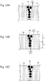
- FIG. 12A shows an example of which cross-sectional shape of the light-absorbing portion 3c is trapezoid
- Fig. 12B shows an example of which cross-sectional shape of the light-absorbing portion 3d has polygonal oblique lines
- Fig. 12C shows an example of which cross-sectional shape of the light-absorbing portion 3e has curved oblique lines.
- the cross-sectional shape of the light-absorbing portion 3c is trapezoid; more specifically, the cross-sectional shape of the light-absorbing portion 3c is a substantially regular trapezoid consisting of: an upper base and a lower base arranged in parallel; and two oblique lines respectively connecting the upper base and the lower base.
- the oblique line intersects with the normal to the output plane of the optical sheet at an angle of ⁇ 1.
- the angle ⁇ 1 is preferably in a range of more than 0 and 10 or less; more preferably more than 0 and 6 or less.
- an oblique line of the light-absorbing portion 3d (an oblique line of the light-transmissive portions 2d, 2d) consists of two lines, but not a single line.
- the cross-sectional shape has polygonal lines. More specifically, the lower base side oblique line (upper side of Fig. 12B ) makes an angle of ⁇ 2 with a normal to the output plane of the optical sheet.
- the upper base side oblique line (lower side of Fig. 12B ) makes an angle of ⁇ 3 with a normal to the output plane of he optical sheet. There is a relation: ⁇ 2 > ⁇ 3.
- Both ⁇ 2 and ⁇ 3 are preferably within the range of more than 0° and 10° or less, and more preferable angles are within the range of more than 0° and 6° or less.
- the size of the oblique line is defined by T1 and T2 in the thickness direction of the optical functional sheet layer (vertical direction of Fig. 12B ).
- the length of T1 and T2 are preferably the same.
- each side of the oblique line in the example of Fig. 12B consists of two oblique lines
- the oblique line may be formed by polygonal line having more than two lines.
- the oblique line of the light-absorbing portion 3e (the oblique line of the light-transmissive portions 2e, 2e, ...) is a curved line.
- the oblique line of the substantially triangle cross-sectional shape of the light-absorbing portion may be a curved line.
- the angle between the curved line and the normal to the output plane of the sheet of the optical sheet at the upper-base-side (lower side in Fig. 12C ) is preferably smaller than the angle at the lower-base-side (upper side in Fig. 12C ).
- every angle on the curved line is preferably within the range of more than 0° and 10° or less, and more preferably within the range of more than 0° and 6° or less.
- the angle between the curved line and the normal to the output plane of the sheet is defined by an angle between the normal to the output plane of the sheet and lines made by dividing a curved line into ten equal parts and connecting two adjacent ends of the segments.
- the shape of the light-absorbing portion is not limited to the examples; it can be adequately modified as long as the shape is suitable for absorbing the external light.
- substantially rectangle cross-sectional shape may be possible.
- the optical sheet of the present invention comprises: at least one optical functional sheet layer obtained by the above described method for manufacturing the optical functional sheet; and other layers having various functions, as needed.
- the layer to be provided to the optical sheet of the invention may be a layer used for the conventional optical sheets and it is not particularly limited. Specific examples thereof include: antireflection layer, adhesive layer, electromagnetic wave shielding layer, wavelength filter layer, anti-glare layer, and hard coating layer.
- the laminating order and number the layers to be laminated are determined depending on the application of the optical sheet. Hereinafter, the functions and so on of these layers will be described.
- the antireflection layer is a layer provided at the nearest side to the observer and has a function of preventing reflection of external light.
- the antireflection layer it is possible to inhibit reflection of the external light at the surface of the observer side of the optical sheet and returning of the reflected light to the observer side that makes it difficult to see the image.
- Such an antireflection layer can be formed, for example, by using a commercially available antireflection film.
- the adhesive layer is a layer in which adhesive is provided; an example of the adhesive may be acrylic adhesive.
- the kind of adhesive is not limited to the acrylic adhesive as long as the adhesive has required performances such as optical transparency, adhesiveness, and weatherability.
- the adhesive force is preferably, for example, from several to 20 N/25 mm.
- antioxidant e.g. benzotriazole
- acid group e.g -COOH
- UV absorber to absorb ultraviolet ray e.g. benzotriazole
- UV absorber to absorb ultraviolet ray is desirably included in the adhesive.
- the electromagnetic wave shielding layer is literally a layer having a function to shield electromagnetic wave.
- the means for shielding electromagnetic wave is not particularly limited. Examples thereof may be a copper mesh. Examples of the method for obtaining the copper mesh include etching and vapor deposition; by the method, it is effective to form a fine copper mesh. Pitches and so on of the copper mesh can be adequately designed depending on the electromagnetic wave to be shielded; a mesh having a pitch of about 300 ⁇ m and a line width of 12 ⁇ m may be exemplified.
- the wavelength filter layer has a function of filtering a light of certain wavelength.
- the wavelength to be filtered can be adequately selected; the wavelength filter layer can have functions of cutting neon line emitted from the PDP and cutting infrared rays and near-infrared ray.
- the anti-glare layer (it is also called AG layer) is a layer to inhibit glare.
- As the anti-glare layer commercially available one can be used.
- the hard coating layer is also called HC layer.
- the hard coating layer is a layer made of a film which exhibits abrasion-resistant to protect the image display from scratching.
- the optical sheet of the present invention has the above described optical functional sheet layer having an improved appearance, the appearance of the optical sheet is also improved.
- the image display device of the present invention comprises the above-described optical sheet of the invention.
- PDP as an image light source
- a plasma display can be obtained. If the light source and a liquid crystal panel are combined, it is possible to obtain a liquid crystal display device.
- a reactor To a reactor, 53.3 parts by mass of bisphenol-A/ethyleneoxide 2 mole-adduct, 34.0 parts by mass of xylylene diisocyanate, and 93.5 parts by mass of phenoxyethyl acrylate were added and reacted at 80 °C for 5 hours; then, 6.2 parts by mass of 2-hydroxyethyl acrylate and 0.03 parts by mass of urethanizing catalyst were added and reacted at 80 °C for 5 hours, to obtain a urethane acrylate-based oligomer (i.e. a light curable oligomer).
- a urethane acrylate-based oligomer i.e. a light curable oligomer
- the obtained adhesive coating fluid was applied to a PET film ("A4300” manufactured by Toyobo Co., Ltd., thickness: 100 ⁇ m) with a thickness of 25 ⁇ m and dried to form an adhesive layer on one surface of the PET film. Then, a mold release film (“E7007” manufactured by Toyobo Co., Ltd.) having a thickness of 38 ⁇ m was adhered on the adhesive layer, to form a base material with an adhesive layer (hereinafter, referred to as "base material 1'".)
- the light-transmissive portions were formed by using an apparatus shown in Fig. 13 . More specifically, firstly, the base material 1' formed in the above step (2) was transported in the arrow x-direction so that the base material 1' was fed between a die roll 32 and a nip roll 31.
- the die roll 32 has a cylindrical shape and the outer circumferential surface has a plurality of grooves cut in a row in the circumferential direction.
- each of the groove is a trapezoid of which upper base has a width (i.e.
- the composition constituting the light-transmissive portion 30 prepared in the above step (1) was fed on the base material 1' (i.e. on the surface of the side where the adhesive layer was not applied.) at the same time from the feeder 38.
- the composition constituting the light-transmissive portion 30 was pressed between the die roll 32 and the nip roll 31; then, by irradiating ultraviolet of 800 mJ/cm 2 by high-pressure mercury vapor lamp from the base material 1' side to the composition constituting the light-transmissive portion, the composition constituting the light-transmissive portion 30 was cured, to form the light-transmissive portion 2 on the base material 1'. Thereafter, the light-transmissive portion 2 was separated from the molding die roll 32 by using mold-releasing nip roll 33; accordingly, a sheet (i.e. an intermediate member) 10' having a thickness of 252 ⁇ 20 ⁇ m including the light-transmissive portion 2 was formed.
- the light-absorbing portions were formed by using an apparatus shown in Fig. 14 . More specifically, firstly, the composition constituting the light-absorbing portion 36 prepared in the above step (4) was fed from a feeder (not shown) onto the intermediate member 10' formed in the above step (3). Then, by using a doctor blade 35 substantially perpendicularly-provided with respect to the transferring direction of the intermediate member 10' (the arrow direction shown in Fig. 14 ), the composition constituting the light-absorbing portion 36 fed onto the intermediate member 10' was filled in the substantially V-shape grooves (groove between the light-transmissive portions 2, 2) 37, 37, ... and the excessive amount of the composition constituting the light-absorbing portion 36 was strickled.
- each light-absorbing portion 3' had at most 5 ⁇ m deep recess from the surface level of the light-transmissive portions 2, 2, ....
- the density of the light-absorbing particles contained in the composition constituting the light-absorbing portion prepared in the above step (4) was changed to 5.0 parts by mass; by using a similar apparatus to the one shown in Fig. 14 , the composition constituting the light-absorbing portion was filled in the grooves between the light-transmissive portions and the excessive amount of the composition constituting the light-absorbing portion was strickled with a doctor blade. Then, by irradiating the composition constituting the light-absorbing portion with ultraviolet ray, the composition was cured and the formation of the light-absorbing portion was completed. As a result, the depth of the surface recess of the light-absorbing portion was improved to be 2 ⁇ m; so, it was possible to produce an optical functional sheet layer having no streaky and belt-like unevenness.
- the term "streaky unevenness” means a defect in appearance which can be seen as white streaky lines in the longitudinal direction of the light-absorbing portion when observing the appearance particularly from a high angle.
- the resin constituting the light-absorbing portion is not sufficiently filled locally, thereby there is a recess.
- the term "belt-like unevenness” means a defect in appearance where contrast can be observed over a wide range in the longitudinal direction of the light-absorbing portion.
- the composition constituting the light-absorbing portion was once filled in the groove and cured in the same manner as Example 1; then, by using a similar apparatus to the one shown in Fig. 14 , a composition constituting the light-absorbing portion prepared in the above step (4) but excluding the light-absorbing particles (i.e. a transparent resin) was filled in the grooves between the light-transmissive portions, and the excessive amount of the composition was strickled with a doctor blade. Then, by irradiating the composition with ultraviolet ray, the composition was cured; and the depth of the surface recess of the light-absorbing portion was improved to be 2 ⁇ m. So, it was possible to produce an optical functional sheet layer having no streaky and belt-like unevenness.
- the light-absorbing particles i.e. a transparent resin
- the composition constituting the light-absorbing portion was once filled in the groove and cured in the same manner as Example 1; then, a composition constituting the light-absorbing portion prepared in the above step (4) but excluding the light-absorbing particles (i.e. a transparent resin) was supplied on the light-absorbing portions 3c, 3c, ... and the light-transmissive portions 2, 2, .... Then, the composition was strickled by using a doctor blade so that the composition covers not only over the light-absorbing portions 3c, 3c, ... but also over the light-transmissive portions 2, 2, ...; and cured by irradiation with ultraviolet ray. As a result, the depth of the surface recess of the light-absorbing portion was improved to be 0.5 ⁇ m. So, it was possible to produce an optical functional sheet layer having no streaky and belt-like unevenness.
- the light-absorbing particles i.e. a transparent resin
- the composition excluding the light-absorbing particle (the transparent resin) was supplied to the light-absorbing portion 3c, 3c, ... and the light-transmissive portions 2, 2, ... in the same manner as Example 3; then, the surface of the side where the composition was supplied was pressed with a mirror-surface imprint mold, and cured by irradiation with ultraviolet. As a result, the depth of the surface recess of the light-absorbing portion was improved to be 0 ⁇ m. So, it was possible to produce an optical functional sheet layer having no streaky and belt-like unevenness.
- Comparative example 1 was carried out in the same manner as Example 1 to produce an optical functional sheet layer. As a result, although the depth of the surface recess of the light-absorbing portion was improved to be 2 ⁇ m, however, streaky and belt-like unevenness occurred.
Landscapes
- Physics & Mathematics (AREA)
- Engineering & Computer Science (AREA)
- General Physics & Mathematics (AREA)
- Optics & Photonics (AREA)
- Health & Medical Sciences (AREA)
- Manufacturing & Machinery (AREA)
- Ophthalmology & Optometry (AREA)
- Mechanical Engineering (AREA)
- Optical Elements Other Than Lenses (AREA)
- Devices For Indicating Variable Information By Combining Individual Elements (AREA)
- Liquid Crystal (AREA)
Priority Applications (1)
| Application Number | Priority Date | Filing Date | Title |
|---|---|---|---|
| EP21161715.4A EP3859409A1 (fr) | 2009-07-06 | 2010-07-02 | Procédé de fabrication de feuille optique, feuille optique et dispositif d'affichage d'images |
Applications Claiming Priority (5)
| Application Number | Priority Date | Filing Date | Title |
|---|---|---|---|
| JP2009160285 | 2009-07-06 | ||
| JP2010135987A JP5573394B2 (ja) | 2009-07-06 | 2010-06-15 | 光学シートの製造方法、光学シート、及び映像表示装置 |
| EP19163517.6A EP3518007B1 (fr) | 2009-07-06 | 2010-07-02 | Feuille optique et dispositif d'affichage d'image |
| PCT/JP2010/061338 WO2011004772A1 (fr) | 2009-07-06 | 2010-07-02 | Procédé de production d'une feuille optique, feuille optique et dispositif d'affichage d'image |
| EP10797083.2A EP2453265B1 (fr) | 2009-07-06 | 2010-07-02 | Procédé de production d'une feuille optique, feuille optique et dispositif d'affichage d'image |
Related Parent Applications (3)
| Application Number | Title | Priority Date | Filing Date |
|---|---|---|---|
| EP19163517.6A Division EP3518007B1 (fr) | 2009-07-06 | 2010-07-02 | Feuille optique et dispositif d'affichage d'image |
| EP19163517.6A Division-Into EP3518007B1 (fr) | 2009-07-06 | 2010-07-02 | Feuille optique et dispositif d'affichage d'image |
| EP10797083.2A Division EP2453265B1 (fr) | 2009-07-06 | 2010-07-02 | Procédé de production d'une feuille optique, feuille optique et dispositif d'affichage d'image |
Related Child Applications (2)
| Application Number | Title | Priority Date | Filing Date |
|---|---|---|---|
| EP21161715.4A Division-Into EP3859409A1 (fr) | 2009-07-06 | 2010-07-02 | Procédé de fabrication de feuille optique, feuille optique et dispositif d'affichage d'images |
| EP21161715.4A Division EP3859409A1 (fr) | 2009-07-06 | 2010-07-02 | Procédé de fabrication de feuille optique, feuille optique et dispositif d'affichage d'images |
Publications (2)
| Publication Number | Publication Date |
|---|---|
| EP3690495A1 true EP3690495A1 (fr) | 2020-08-05 |
| EP3690495B1 EP3690495B1 (fr) | 2021-04-21 |
Family
ID=43429194
Family Applications (4)
| Application Number | Title | Priority Date | Filing Date |
|---|---|---|---|
| EP19163517.6A Active EP3518007B1 (fr) | 2009-07-06 | 2010-07-02 | Feuille optique et dispositif d'affichage d'image |
| EP20161820.4A Active EP3690495B1 (fr) | 2009-07-06 | 2010-07-02 | Procédé de fabrication de feuille optique, feuille optique et dispositif d'affichage d'images |
| EP10797083.2A Active EP2453265B1 (fr) | 2009-07-06 | 2010-07-02 | Procédé de production d'une feuille optique, feuille optique et dispositif d'affichage d'image |
| EP21161715.4A Withdrawn EP3859409A1 (fr) | 2009-07-06 | 2010-07-02 | Procédé de fabrication de feuille optique, feuille optique et dispositif d'affichage d'images |
Family Applications Before (1)
| Application Number | Title | Priority Date | Filing Date |
|---|---|---|---|
| EP19163517.6A Active EP3518007B1 (fr) | 2009-07-06 | 2010-07-02 | Feuille optique et dispositif d'affichage d'image |
Family Applications After (2)
| Application Number | Title | Priority Date | Filing Date |
|---|---|---|---|
| EP10797083.2A Active EP2453265B1 (fr) | 2009-07-06 | 2010-07-02 | Procédé de production d'une feuille optique, feuille optique et dispositif d'affichage d'image |
| EP21161715.4A Withdrawn EP3859409A1 (fr) | 2009-07-06 | 2010-07-02 | Procédé de fabrication de feuille optique, feuille optique et dispositif d'affichage d'images |
Country Status (4)
| Country | Link |
|---|---|
| US (1) | US8480242B2 (fr) |
| EP (4) | EP3518007B1 (fr) |
| JP (1) | JP5573394B2 (fr) |
| WO (1) | WO2011004772A1 (fr) |
Families Citing this family (20)
| Publication number | Priority date | Publication date | Assignee | Title |
|---|---|---|---|---|
| JP5751480B2 (ja) * | 2011-04-19 | 2015-07-22 | 大日本印刷株式会社 | 掻取装置、これを備えたコントラスト向上シートの製造装置、およびコントラスト向上シートの製造方法 |
| JP2013003530A (ja) * | 2011-06-21 | 2013-01-07 | Dainippon Printing Co Ltd | 光学シート、この光学シートを備える表示装置用光学フィルタおよび表示装置、ならびにこの光学シートの製造方法 |
| JP5966302B2 (ja) * | 2011-09-30 | 2016-08-10 | 大日本印刷株式会社 | 光学シートの製造方法 |
| JP5994325B2 (ja) * | 2012-03-27 | 2016-09-21 | 大日本印刷株式会社 | 光学シート、これを備えた表示装置、および光学シートの製造方法 |
| JP6186760B2 (ja) * | 2012-06-06 | 2017-08-30 | 大日本印刷株式会社 | スクリーン、及びスクリーンの製造方法 |
| US20140110040A1 (en) * | 2012-10-23 | 2014-04-24 | Ronald Steven Cok | Imprinted micro-louver structure method |
| JP6089605B2 (ja) * | 2012-11-06 | 2017-03-08 | 大日本印刷株式会社 | スクリーン及びスクリーンの製造方法 |
| WO2014147793A1 (fr) | 2013-03-21 | 2014-09-25 | 大日本印刷株式会社 | Feuille d'éclairage, panneau d'éclairage, écran d'éclairage enroulable/déroulable et procédé de fabrication de feuille d'éclairage |
| US10641448B2 (en) | 2013-03-21 | 2020-05-05 | Dai Nippon Printing Co., Ltd. | Daylighting sheet, daylighting panel and roll-up daylighting screen |
| US20150109674A1 (en) * | 2013-10-23 | 2015-04-23 | Ronald Steven Cok | Imprinted micro-louver structure |
| JP6225673B2 (ja) * | 2013-12-02 | 2017-11-08 | 大日本印刷株式会社 | ウィンドウフィルム |
| JP5910644B2 (ja) * | 2014-01-27 | 2016-04-27 | 大日本印刷株式会社 | 採光フィルムおよび採光フィルムの製造方法 |
| WO2016190430A1 (fr) * | 2015-05-28 | 2016-12-01 | 大日本印刷株式会社 | Élément de commande de lumière et verre stratifié à fonction de commande de lumière l'utilisant |
| JP2016014887A (ja) * | 2015-08-20 | 2016-01-28 | 大日本印刷株式会社 | 採光シートの製造方法 |
| JP2016066098A (ja) * | 2015-12-28 | 2016-04-28 | 大日本印刷株式会社 | 採光フィルムおよび採光フィルムの製造方法 |
| JP6057199B2 (ja) * | 2016-03-31 | 2017-01-11 | 大日本印刷株式会社 | 採光フィルム、採光具および採光フィルムの製造方法 |
| KR102585238B1 (ko) * | 2017-12-28 | 2023-10-06 | 삼성디스플레이 주식회사 | 유기 발광 표시 장치 및 이의 제조 방법 |
| JP2021076645A (ja) * | 2019-11-06 | 2021-05-20 | 大日本印刷株式会社 | 光学シート及びその製造方法並びに光学シート用母材シート及びその製造方法 |
| CN113050207A (zh) * | 2019-12-26 | 2021-06-29 | 天马日本株式会社 | 光线方向控制元件、其制造方法以及成像元件 |
| CN114981073B (zh) * | 2020-01-14 | 2024-09-17 | 株式会社Lg化学 | 光控制膜制造设备及由光控制膜制造设备制造的光控制膜 |
Citations (4)
| Publication number | Priority date | Publication date | Assignee | Title |
|---|---|---|---|---|
| JP2008146074A (ja) | 2006-12-12 | 2008-06-26 | Samsung Corning Co Ltd | ディスプレイ装置用外光遮蔽フィルムおよびこの製造方法、これを含むディスプレイ装置用フィルタ |
| US20090091824A1 (en) * | 2005-02-24 | 2009-04-09 | Dai Nippon Printing Co., Ltd. | Light-Diffusing Member, Transmission Type Screen, Rear-Projection-Type Display, and Light-Absorbing-Part-Forming Resin Composition |
| JP2009080198A (ja) * | 2007-09-25 | 2009-04-16 | Dainippon Printing Co Ltd | 光学シート、及び該光学シートを備える表示装置 |
| JP2009086682A (ja) * | 2008-12-16 | 2009-04-23 | Dainippon Printing Co Ltd | 二次元視野角拡大部材および表示装置 |
Family Cites Families (3)
| Publication number | Priority date | Publication date | Assignee | Title |
|---|---|---|---|---|
| JP2008083371A (ja) | 2006-09-27 | 2008-04-10 | Pilot Ink Co Ltd | 書き方学習教材セット |
| JP4882635B2 (ja) * | 2006-09-27 | 2012-02-22 | 大日本印刷株式会社 | 光学シート及び表示装置 |
| JP4977083B2 (ja) * | 2007-04-26 | 2012-07-18 | サムスンコーニング精密素材株式会社 | ディスプレイ装置用光学部材およびこれを含んだディスプレイ装置用フィルタ |
-
2010
- 2010-06-15 JP JP2010135987A patent/JP5573394B2/ja active Active
- 2010-07-02 EP EP19163517.6A patent/EP3518007B1/fr active Active
- 2010-07-02 EP EP20161820.4A patent/EP3690495B1/fr active Active
- 2010-07-02 EP EP10797083.2A patent/EP2453265B1/fr active Active
- 2010-07-02 EP EP21161715.4A patent/EP3859409A1/fr not_active Withdrawn
- 2010-07-02 US US12/829,578 patent/US8480242B2/en active Active
- 2010-07-02 WO PCT/JP2010/061338 patent/WO2011004772A1/fr active Application Filing
Patent Citations (4)
| Publication number | Priority date | Publication date | Assignee | Title |
|---|---|---|---|---|
| US20090091824A1 (en) * | 2005-02-24 | 2009-04-09 | Dai Nippon Printing Co., Ltd. | Light-Diffusing Member, Transmission Type Screen, Rear-Projection-Type Display, and Light-Absorbing-Part-Forming Resin Composition |
| JP2008146074A (ja) | 2006-12-12 | 2008-06-26 | Samsung Corning Co Ltd | ディスプレイ装置用外光遮蔽フィルムおよびこの製造方法、これを含むディスプレイ装置用フィルタ |
| JP2009080198A (ja) * | 2007-09-25 | 2009-04-16 | Dainippon Printing Co Ltd | 光学シート、及び該光学シートを備える表示装置 |
| JP2009086682A (ja) * | 2008-12-16 | 2009-04-23 | Dainippon Printing Co Ltd | 二次元視野角拡大部材および表示装置 |
Also Published As
| Publication number | Publication date |
|---|---|
| US20110043921A1 (en) | 2011-02-24 |
| JP2011034060A (ja) | 2011-02-17 |
| EP2453265B1 (fr) | 2019-05-15 |
| JP5573394B2 (ja) | 2014-08-20 |
| EP3690495B1 (fr) | 2021-04-21 |
| EP3518007B1 (fr) | 2020-04-22 |
| EP2453265A4 (fr) | 2017-12-13 |
| EP3518007A1 (fr) | 2019-07-31 |
| EP2453265A1 (fr) | 2012-05-16 |
| EP3859409A1 (fr) | 2021-08-04 |
| US8480242B2 (en) | 2013-07-09 |
| WO2011004772A1 (fr) | 2011-01-13 |
Similar Documents
| Publication | Publication Date | Title |
|---|---|---|
| EP3690495B1 (fr) | Procédé de fabrication de feuille optique, feuille optique et dispositif d'affichage d'images | |
| US10479931B2 (en) | Polymer molding composition, wavelength converter, backlight unit, and liquid crystal display device | |
| US20160109623A1 (en) | Display device | |
| JP5994325B2 (ja) | 光学シート、これを備えた表示装置、および光学シートの製造方法 | |
| JP5678441B2 (ja) | 光学シートの製造方法 | |
| JP2015135501A (ja) | 光学シートロール、並びに、光学シートロール、光学シート、及び表示装置の製造方法 | |
| JP2012113054A (ja) | 光学シートとその作製方法、映像表示装置、及び金型ロールとその作製方法 | |
| JP5725398B2 (ja) | 視認性向上シート | |
| JP2012118100A (ja) | 光学シートとその作製方法、映像表示装置、及び金型ロールとその作製方法 | |
| JP2012150356A (ja) | 光学シート、表示装置、及び光学シートの製造方法 | |
| JP5729630B2 (ja) | 着色インキ組成物およびそれを用いた視認性向上シート | |
| JP6036921B2 (ja) | 光学シート、及び映像表示装置 | |
| JP5807323B2 (ja) | 光学シート、及び映像表示装置 | |
| JP2011232745A (ja) | 光学機能シート、光学シート及び映像表示装置 | |
| JP2012150357A (ja) | 光学シート、及び表示装置 | |
| KR20160052972A (ko) | 광학시트 및 이를 포함하는 광학 디스플레이 장치 | |
| JP2012181333A (ja) | Pdp用コントラスト向上フィルタ、このフィルタの製造方法及びこのフィルタを用いたプラズマディスプレイ装置 | |
| JP5740856B2 (ja) | 光学シート、光学シートの製造方法、及び映像表示装置 | |
| JP2013003530A (ja) | 光学シート、この光学シートを備える表示装置用光学フィルタおよび表示装置、ならびにこの光学シートの製造方法 | |
| JP2012168430A (ja) | コントラスト向上フィルタの製造方法 | |
| JP2015028660A (ja) | 光学シートの製造方法、光学シート | |
| JP2015184322A (ja) | 光制御シート、映像源ユニット、及び光制御シートの製造方法 | |
| JP2012056137A (ja) | 金型の製造方法、金型、光学機能シート、光学シート、及び映像表示装置 |
Legal Events
| Date | Code | Title | Description |
|---|---|---|---|
| PUAI | Public reference made under article 153(3) epc to a published international application that has entered the european phase |
Free format text: ORIGINAL CODE: 0009012 |
|
| STAA | Information on the status of an ep patent application or granted ep patent |
Free format text: STATUS: THE APPLICATION HAS BEEN PUBLISHED |
|
| AC | Divisional application: reference to earlier application |
Ref document number: 3518007 Country of ref document: EP Kind code of ref document: P Ref document number: 2453265 Country of ref document: EP Kind code of ref document: P |
|
| AK | Designated contracting states |
Kind code of ref document: A1 Designated state(s): AL AT BE BG CH CY CZ DE DK EE ES FI FR GB GR HR HU IE IS IT LI LT LU LV MC MK MT NL NO PL PT RO SE SI SK SM TR |
|
| STAA | Information on the status of an ep patent application or granted ep patent |
Free format text: STATUS: REQUEST FOR EXAMINATION WAS MADE |
|
| 17P | Request for examination filed |
Effective date: 20200803 |
|
| RBV | Designated contracting states (corrected) |
Designated state(s): AL AT BE BG CH CY CZ DE DK EE ES FI FR GB GR HR HU IE IS IT LI LT LU LV MC MK MT NL NO PL PT RO SE SI SK SM TR |
|
| GRAP | Despatch of communication of intention to grant a patent |
Free format text: ORIGINAL CODE: EPIDOSNIGR1 |
|
| STAA | Information on the status of an ep patent application or granted ep patent |
Free format text: STATUS: GRANT OF PATENT IS INTENDED |
|
| RIC1 | Information provided on ipc code assigned before grant |
Ipc: G02B 5/20 20060101ALI20201016BHEP Ipc: B29D 11/00 20060101ALI20201016BHEP Ipc: F21S 2/00 20160101ALI20201016BHEP Ipc: F21V 3/04 20180101ALI20201016BHEP Ipc: G02B 5/00 20060101AFI20201016BHEP Ipc: G02F 1/1335 20060101ALI20201016BHEP |
|
| INTG | Intention to grant announced |
Effective date: 20201110 |
|
| GRAS | Grant fee paid |
Free format text: ORIGINAL CODE: EPIDOSNIGR3 |
|
| GRAA | (expected) grant |
Free format text: ORIGINAL CODE: 0009210 |
|
| STAA | Information on the status of an ep patent application or granted ep patent |
Free format text: STATUS: THE PATENT HAS BEEN GRANTED |
|
| AC | Divisional application: reference to earlier application |
Ref document number: 3518007 Country of ref document: EP Kind code of ref document: P Ref document number: 2453265 Country of ref document: EP Kind code of ref document: P |
|
| AK | Designated contracting states |
Kind code of ref document: B1 Designated state(s): AL AT BE BG CH CY CZ DE DK EE ES FI FR GB GR HR HU IE IS IT LI LT LU LV MC MK MT NL NO PL PT RO SE SI SK SM TR |
|
| REG | Reference to a national code |
Ref country code: GB Ref legal event code: FG4D |
|
| REG | Reference to a national code |
Ref country code: CH Ref legal event code: EP |
|
| REG | Reference to a national code |
Ref country code: DE Ref legal event code: R096 Ref document number: 602010066867 Country of ref document: DE |
|
| REG | Reference to a national code |
Ref country code: IE Ref legal event code: FG4D |
|
| REG | Reference to a national code |
Ref country code: AT Ref legal event code: REF Ref document number: 1385233 Country of ref document: AT Kind code of ref document: T Effective date: 20210515 |
|
| REG | Reference to a national code |
Ref country code: LT Ref legal event code: MG9D |
|
| REG | Reference to a national code |
Ref country code: AT Ref legal event code: MK05 Ref document number: 1385233 Country of ref document: AT Kind code of ref document: T Effective date: 20210421 |
|
| REG | Reference to a national code |
Ref country code: NL Ref legal event code: MP Effective date: 20210421 |
|
| PG25 | Lapsed in a contracting state [announced via postgrant information from national office to epo] |
Ref country code: NL Free format text: LAPSE BECAUSE OF FAILURE TO SUBMIT A TRANSLATION OF THE DESCRIPTION OR TO PAY THE FEE WITHIN THE PRESCRIBED TIME-LIMIT Effective date: 20210421 Ref country code: BG Free format text: LAPSE BECAUSE OF FAILURE TO SUBMIT A TRANSLATION OF THE DESCRIPTION OR TO PAY THE FEE WITHIN THE PRESCRIBED TIME-LIMIT Effective date: 20210721 Ref country code: AT Free format text: LAPSE BECAUSE OF FAILURE TO SUBMIT A TRANSLATION OF THE DESCRIPTION OR TO PAY THE FEE WITHIN THE PRESCRIBED TIME-LIMIT Effective date: 20210421 Ref country code: HR Free format text: LAPSE BECAUSE OF FAILURE TO SUBMIT A TRANSLATION OF THE DESCRIPTION OR TO PAY THE FEE WITHIN THE PRESCRIBED TIME-LIMIT Effective date: 20210421 Ref country code: LT Free format text: LAPSE BECAUSE OF FAILURE TO SUBMIT A TRANSLATION OF THE DESCRIPTION OR TO PAY THE FEE WITHIN THE PRESCRIBED TIME-LIMIT Effective date: 20210421 Ref country code: FI Free format text: LAPSE BECAUSE OF FAILURE TO SUBMIT A TRANSLATION OF THE DESCRIPTION OR TO PAY THE FEE WITHIN THE PRESCRIBED TIME-LIMIT Effective date: 20210421 |
|
| PG25 | Lapsed in a contracting state [announced via postgrant information from national office to epo] |
Ref country code: NO Free format text: LAPSE BECAUSE OF FAILURE TO SUBMIT A TRANSLATION OF THE DESCRIPTION OR TO PAY THE FEE WITHIN THE PRESCRIBED TIME-LIMIT Effective date: 20210721 Ref country code: LV Free format text: LAPSE BECAUSE OF FAILURE TO SUBMIT A TRANSLATION OF THE DESCRIPTION OR TO PAY THE FEE WITHIN THE PRESCRIBED TIME-LIMIT Effective date: 20210421 Ref country code: PL Free format text: LAPSE BECAUSE OF FAILURE TO SUBMIT A TRANSLATION OF THE DESCRIPTION OR TO PAY THE FEE WITHIN THE PRESCRIBED TIME-LIMIT Effective date: 20210421 Ref country code: PT Free format text: LAPSE BECAUSE OF FAILURE TO SUBMIT A TRANSLATION OF THE DESCRIPTION OR TO PAY THE FEE WITHIN THE PRESCRIBED TIME-LIMIT Effective date: 20210823 Ref country code: SE Free format text: LAPSE BECAUSE OF FAILURE TO SUBMIT A TRANSLATION OF THE DESCRIPTION OR TO PAY THE FEE WITHIN THE PRESCRIBED TIME-LIMIT Effective date: 20210421 Ref country code: IS Free format text: LAPSE BECAUSE OF FAILURE TO SUBMIT A TRANSLATION OF THE DESCRIPTION OR TO PAY THE FEE WITHIN THE PRESCRIBED TIME-LIMIT Effective date: 20210821 Ref country code: GR Free format text: LAPSE BECAUSE OF FAILURE TO SUBMIT A TRANSLATION OF THE DESCRIPTION OR TO PAY THE FEE WITHIN THE PRESCRIBED TIME-LIMIT Effective date: 20210722 |
|
| REG | Reference to a national code |
Ref country code: DE Ref legal event code: R097 Ref document number: 602010066867 Country of ref document: DE |
|
| PG25 | Lapsed in a contracting state [announced via postgrant information from national office to epo] |
Ref country code: EE Free format text: LAPSE BECAUSE OF FAILURE TO SUBMIT A TRANSLATION OF THE DESCRIPTION OR TO PAY THE FEE WITHIN THE PRESCRIBED TIME-LIMIT Effective date: 20210421 Ref country code: ES Free format text: LAPSE BECAUSE OF FAILURE TO SUBMIT A TRANSLATION OF THE DESCRIPTION OR TO PAY THE FEE WITHIN THE PRESCRIBED TIME-LIMIT Effective date: 20210421 Ref country code: SK Free format text: LAPSE BECAUSE OF FAILURE TO SUBMIT A TRANSLATION OF THE DESCRIPTION OR TO PAY THE FEE WITHIN THE PRESCRIBED TIME-LIMIT Effective date: 20210421 Ref country code: SM Free format text: LAPSE BECAUSE OF FAILURE TO SUBMIT A TRANSLATION OF THE DESCRIPTION OR TO PAY THE FEE WITHIN THE PRESCRIBED TIME-LIMIT Effective date: 20210421 Ref country code: RO Free format text: LAPSE BECAUSE OF FAILURE TO SUBMIT A TRANSLATION OF THE DESCRIPTION OR TO PAY THE FEE WITHIN THE PRESCRIBED TIME-LIMIT Effective date: 20210421 Ref country code: DK Free format text: LAPSE BECAUSE OF FAILURE TO SUBMIT A TRANSLATION OF THE DESCRIPTION OR TO PAY THE FEE WITHIN THE PRESCRIBED TIME-LIMIT Effective date: 20210421 Ref country code: CZ Free format text: LAPSE BECAUSE OF FAILURE TO SUBMIT A TRANSLATION OF THE DESCRIPTION OR TO PAY THE FEE WITHIN THE PRESCRIBED TIME-LIMIT Effective date: 20210421 |
|
| PLBE | No opposition filed within time limit |
Free format text: ORIGINAL CODE: 0009261 |
|
| STAA | Information on the status of an ep patent application or granted ep patent |
Free format text: STATUS: NO OPPOSITION FILED WITHIN TIME LIMIT |
|
| REG | Reference to a national code |
Ref country code: CH Ref legal event code: PL |
|
| 26N | No opposition filed |
Effective date: 20220124 |
|
| PG25 | Lapsed in a contracting state [announced via postgrant information from national office to epo] |
Ref country code: MC Free format text: LAPSE BECAUSE OF FAILURE TO SUBMIT A TRANSLATION OF THE DESCRIPTION OR TO PAY THE FEE WITHIN THE PRESCRIBED TIME-LIMIT Effective date: 20210421 |
|
| REG | Reference to a national code |
Ref country code: BE Ref legal event code: MM Effective date: 20210731 |
|
| PG25 | Lapsed in a contracting state [announced via postgrant information from national office to epo] |
Ref country code: LI Free format text: LAPSE BECAUSE OF NON-PAYMENT OF DUE FEES Effective date: 20210731 Ref country code: CH Free format text: LAPSE BECAUSE OF NON-PAYMENT OF DUE FEES Effective date: 20210731 |
|
| PG25 | Lapsed in a contracting state [announced via postgrant information from national office to epo] |
Ref country code: IS Free format text: LAPSE BECAUSE OF FAILURE TO SUBMIT A TRANSLATION OF THE DESCRIPTION OR TO PAY THE FEE WITHIN THE PRESCRIBED TIME-LIMIT Effective date: 20210821 Ref country code: LU Free format text: LAPSE BECAUSE OF NON-PAYMENT OF DUE FEES Effective date: 20210702 Ref country code: AL Free format text: LAPSE BECAUSE OF FAILURE TO SUBMIT A TRANSLATION OF THE DESCRIPTION OR TO PAY THE FEE WITHIN THE PRESCRIBED TIME-LIMIT Effective date: 20210421 |
|
| PG25 | Lapsed in a contracting state [announced via postgrant information from national office to epo] |
Ref country code: IT Free format text: LAPSE BECAUSE OF FAILURE TO SUBMIT A TRANSLATION OF THE DESCRIPTION OR TO PAY THE FEE WITHIN THE PRESCRIBED TIME-LIMIT Effective date: 20210421 Ref country code: IE Free format text: LAPSE BECAUSE OF NON-PAYMENT OF DUE FEES Effective date: 20210702 Ref country code: BE Free format text: LAPSE BECAUSE OF NON-PAYMENT OF DUE FEES Effective date: 20210731 |
|
| PG25 | Lapsed in a contracting state [announced via postgrant information from national office to epo] |
Ref country code: CY Free format text: LAPSE BECAUSE OF FAILURE TO SUBMIT A TRANSLATION OF THE DESCRIPTION OR TO PAY THE FEE WITHIN THE PRESCRIBED TIME-LIMIT Effective date: 20210421 |
|
| P01 | Opt-out of the competence of the unified patent court (upc) registered |
Effective date: 20230524 |
|
| PG25 | Lapsed in a contracting state [announced via postgrant information from national office to epo] |
Ref country code: HU Free format text: LAPSE BECAUSE OF FAILURE TO SUBMIT A TRANSLATION OF THE DESCRIPTION OR TO PAY THE FEE WITHIN THE PRESCRIBED TIME-LIMIT; INVALID AB INITIO Effective date: 20100702 |
|
| PGFP | Annual fee paid to national office [announced via postgrant information from national office to epo] |
Ref country code: GB Payment date: 20230721 Year of fee payment: 14 |
|
| PGFP | Annual fee paid to national office [announced via postgrant information from national office to epo] |
Ref country code: FR Payment date: 20230726 Year of fee payment: 14 Ref country code: DE Payment date: 20230719 Year of fee payment: 14 |
|
| PG25 | Lapsed in a contracting state [announced via postgrant information from national office to epo] |
Ref country code: MK Free format text: LAPSE BECAUSE OF FAILURE TO SUBMIT A TRANSLATION OF THE DESCRIPTION OR TO PAY THE FEE WITHIN THE PRESCRIBED TIME-LIMIT Effective date: 20210421 |
|
| PG25 | Lapsed in a contracting state [announced via postgrant information from national office to epo] |
Ref country code: TR Free format text: LAPSE BECAUSE OF FAILURE TO SUBMIT A TRANSLATION OF THE DESCRIPTION OR TO PAY THE FEE WITHIN THE PRESCRIBED TIME-LIMIT Effective date: 20210421 |