EP3687846B1 - Fixation d'un enjoliveur sur joint de vitrage - Google Patents
Fixation d'un enjoliveur sur joint de vitrage Download PDFInfo
- Publication number
- EP3687846B1 EP3687846B1 EP18773193.0A EP18773193A EP3687846B1 EP 3687846 B1 EP3687846 B1 EP 3687846B1 EP 18773193 A EP18773193 A EP 18773193A EP 3687846 B1 EP3687846 B1 EP 3687846B1
- Authority
- EP
- European Patent Office
- Prior art keywords
- trim
- clips
- fastening element
- seal
- base
- Prior art date
- Legal status (The legal status is an assumption and is not a legal conclusion. Google has not performed a legal analysis and makes no representation as to the accuracy of the status listed.)
- Active
Links
Images
Classifications
-
- B—PERFORMING OPERATIONS; TRANSPORTING
- B60—VEHICLES IN GENERAL
- B60J—WINDOWS, WINDSCREENS, NON-FIXED ROOFS, DOORS, OR SIMILAR DEVICES FOR VEHICLES; REMOVABLE EXTERNAL PROTECTIVE COVERINGS SPECIALLY ADAPTED FOR VEHICLES
- B60J10/00—Sealing arrangements
- B60J10/20—Sealing arrangements characterised by the shape
- B60J10/26—Sealing arrangements characterised by the shape characterised by the surface shape
- B60J10/265—Sealing arrangements characterised by the shape characterised by the surface shape the surface being primarily decorative
-
- B—PERFORMING OPERATIONS; TRANSPORTING
- B60—VEHICLES IN GENERAL
- B60J—WINDOWS, WINDSCREENS, NON-FIXED ROOFS, DOORS, OR SIMILAR DEVICES FOR VEHICLES; REMOVABLE EXTERNAL PROTECTIVE COVERINGS SPECIALLY ADAPTED FOR VEHICLES
- B60J10/00—Sealing arrangements
- B60J10/30—Sealing arrangements characterised by the fastening means
- B60J10/36—Sealing arrangements characterised by the fastening means using separately inserted fastening means, e.g. using clips, beads or strips
-
- B—PERFORMING OPERATIONS; TRANSPORTING
- B60—VEHICLES IN GENERAL
- B60R—VEHICLES, VEHICLE FITTINGS, OR VEHICLE PARTS, NOT OTHERWISE PROVIDED FOR
- B60R13/00—Elements for body-finishing, identifying, or decorating; Arrangements or adaptations for advertising purposes
- B60R13/04—External Ornamental or guard strips; Ornamental inscriptive devices thereon
Definitions
- the invention relates to the fixing of a trim on a seal arranged on the periphery of a window mounted on the body of a vehicle.
- hubcaps coated with a metallic film.
- These hubcaps must be fixed in a sufficiently strong manner to avoid the risk of accidentally coming off. They must also be able to be detached, for example, during painting work or when replacing the hubcap in the event of a defect, without requiring the complete replacement of the glass.
- a hubcap fastener comprising two separate elements, the first element being a base which is molded directly with the seal and the second comprising the clips intended to receive the tenon of the hubcap.
- the second element is assembled to the base by an engagement of the two elements with respect to each other in a movement opposing the separation of the two elements.
- the invention proposes a fixing element (100) for a trim (1) on a peripheral seal (10) of a window (11) of a vehicle comprising at least one clip-type assembly consisting of a base (6) bearing on the face intended to receive the trim, one or more semi-rigid clips (7), said clips comprising at least two branches between which a tenon element (4) of the trim is introduced.
- the fixing element (100) is formed from a single piece, comprising the base (6) and one or more semi-rigid clips (7), which is integral with the peripheral seal during the molding thereof on the glazing.
- the one or more semi-rigid clamps (7) of the fixing element constitute the part of the fixing element into which the trim will be clipped.
- the trim is attached after the seal has been formed.
- the gaskets which include the elements involved in this attachment, are formed directly onto the glazing by molding. This operation is known as encapsulation.
- Direct molding of the gaskets and the trim attachment element onto the glazing has the advantage of simplifying the assembly process of the fixing element as well as the trim but above all of reducing the size of this fixing element while reducing the phenomenon of shrinkage.
- the branches of the clamps provide the mechanical connection with the trim.
- the installation of the trim by inserting the tenon between the branches of the clamp(s) completes the operation by preventing the movement which would allow the separation of the two elements.
- the part of the fixing element incorporated in the seal is referred to as the base, and the part comprising the branches of the clamps is referred to as the clamps.
- the fixing element comprises a base 6 which is taken into the seal during the molding thereof.
- the fixing element also comprises a clamp 7 intended to receive in a semi-rigid manner the tenon 4 of the trim 1.
- the clamp 7 is integral with the base 6 and thus constitutes a single part comprising the base 6 and the clamp 7.
- FIG. 2 shows an arrangement of the fixing method in the seal 10 of the edge of the glazing 11 for this method of assembly by encapsulation.
- the trim not shown, is put in place after the assembly in question.
- the fixing element as shown in the Figure 2 is taken into the seal 10 during its molding on the glazing. Only the upper face of the base 6 including the clamps 7 emerges from the seal 10 the rest is taken into the seal. The clamps 7 are located outside the seal 10.
- Joint 10 of the Figure 2 has a shim 12 on which the edge of the trim rests to prevent contact with the vehicle body, and an end stop 13 which is located at the end in the length of the trim.
- the shim 12 and the stop 13 are produced with the main body of the seal by molding.
- the base 6 consists of an elongated body and of dimensions such that they allow incorporation into the joint during molding. Thus, insertion into the joint is done easily and repeatably in the encapsulation mold.
- the glazings concerned are often slightly curved in shape, and the positioning of the bases 6 in the joint 10 may not be strictly aligned with the part of the tenon facing them.
- the presence of two clamps 7 makes it possible to compensate for certain positioning differences.
- the tenon 4 which has a shape that is generally complementary to the space existing between the two branches of the clamps 7, advantageously does not necessarily fill it completely.
- the space in question is preferably slightly larger than the end of the tenon 4.
- a guide finger which mainly serves to guide the tenon 4 of the hubcap towards the clamps.
- This guide finger can be arranged between the two clamps 7. This wedge advances slightly relative to the bottom of the space between the clamps so that the tip of the tenon rests on the bottom of this wedge holding the hips of the tenon 4 against the branches of the clamps 7 by playing on the relative elasticity of these clamps.
Landscapes
- Engineering & Computer Science (AREA)
- Mechanical Engineering (AREA)
- Seal Device For Vehicle (AREA)
- Connection Of Plates (AREA)
- Clamps And Clips (AREA)
- Snaps, Bayonet Connections, Set Pins, And Snap Rings (AREA)
Description
- L'invention concerne la fixation d'un enjoliveur sur un joint disposé à la périphérie d'un vitrage monté sur la carrosserie d'un véhicule.
- Les vitrages fixes montés dans les baies de carrosserie comportent très usuellement un joint disposé à leur périphérie qui assure l'étanchéité et évite le contact verre/métal. Le collage du vitrage dans la baie est aussi effectué par l'intermédiaire du joint.
- Les constructeurs dissimulent souvent ces joints peu esthétiques derrière des enjoliveurs métalliques ou de matériau synthétique revêtu d'un film métallique. Ces enjoliveurs doivent être fixés de manière suffisamment résistante pour ne pas risquer de se détacher accidentellement. Ils doivent aussi pouvoir être désolidarisés par exemple à l'occasion de travaux de ou lors d'un remplacement de l'enjoliveur en cas de défaut de celui-ci, ne nécessitant pas un remplacement du vitrage complet peinture effectués sur le véhicule.
- Divers modes de fixation ont été proposés pour ces enjoliveurs, modes qui souvent impliquent une liaison entre le joint et l'enjoliveur. Le plus souvent ces fixations se font par l'intermédiaire de moyens de type clips pour la simplicité et la rapidité de mise en place. Dans ces assemblages l'enjoliveur qui est constitué essentiellement d'un profilé métallique vient se fixer sur une pièce incorporée dans le joint lui-même. La mise en place des divers éléments nécessite souvent une ou plusieurs opérations qui ne peuvent être effectuées que manuellement ce qui n'est pas satisfaisant du point de vue économique. Pour simplifier ces opérations des solutions ont recours à des modes de fixation comportant le clipsage du profilé constituant l'enjoliveur sur un élément correspondant, intégré dans le joint périphérique dès la formation de celui-ci sur le vitrage. Notamment, il a été proposé dans la demande de brevet belge
BE 2013/0441 - Ainsi, pour répondre à ce problème de retassures et d'encombrement spatial, l'invention propose un élément de fixation (100) d'un enjoliveur (1) sur un joint périphérique (10) d'un vitrage (11) d'un véhicule comprenant au moins un assemblage de type clips constitué d'une base (6) portant sur la face destinée à recevoir l'enjoliveur, une ou plusieurs pinces semi-rigides (7), lesdites pinces comprenant aux moins deux branches entre lesquelles est introduit un élément tenon(4) de l'enjoliveur.
- Selon l'invention, l'élément de fixation (100) est formé d'une seule pièce, comprenant la base (6) et une ou plusieurs pinces semi-rigides (7), qui est solidaire du joint périphérique au cours du moulage de celui-ci sur le vitrage.
- Selon l'invention, la une ou plusieurs pinces semi-rigides (7) l'élément de fixation constitue la partie de l'élément de fixation dans laquelle l'enjoliveur sera clipsé. L'enjoliveur est rapporté après formation du joint.
- Les joints qui comportent les éléments participant à cette fixation, sont formés directement sur le vitrage par moulage. On désigne l'opération sous le nom d'encapsulation. Le moulage direct des joints ainsi que de l'élément de fixation de l'enjoliveur sur le vitrage présente l'avantage de simplifier le procéder de montage de l'élément de fixation ainsi que de l'enjoliveur mais surtout de diminuer l'encombrement de cet élément de fixation tout en réduisant le phénomène de retassures.
- Selon l'invention, les branches des pinces assurent la liaison de nature mécanique avec l'enjoliveur. La mise en place de l'enjoliveur par insertion du tenon entre les branches de la ou les pinces complète l'opération en interdisant le mouvement qui permettrait la séparation des deux éléments.
- Dans la suite, la partie de l'élément de fixation incorporé dans le joint est désigné sous le nom de base, et la partie comprenant les branches des pinces, les pinces. Ces deux éléments selon l'invention forme une unique pièce qui est moulé directement sur le vitrage sur le joint périphérique.
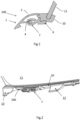
- L'invention est décrite de manière détaillée en faisant référence aux figures dans lesquelles :
- la
figure 1 présente en coupe le mode de fixation par clipsage selon l'invention ; - la
figure 2 présente en perspective le vitrage avec l'élément de clipsage incorporé dans le joint d'encapsulation ; - La
figure 1 montre en coupe de façon schématique le mode d'assemblage par clipsage. Dans cette représentation l'enjoliveur 1 présente une surface extérieure 2 destinée à dissimuler le joint d'encapsulation 10 du vitrage 11. Sur sa face tournée vers le joint, l'enjoliveur comporte un tenon 4. Selon l'invention, l'élément fixation est en plastique de type ABS-PC réalisé au moyen d'un procédé d'injection par moulage. La matière utilisée doit présenter une flexibilité suffisante pour assurer la fonction de clipsage, ainsi qu'une adhésion avec, selon l'invention, la matière plastique de type TPE ou PVC d'encapsulation. - L'élément de fixation comprend une base 6 laquelle est prise dans le joint lors du moulage de celui-ci. L'élément de fixation comprend aussi une pince 7 destinée à recevoir de manière semi-rigide le tenon 4 de l'enjoliveur 1. La pince 7 est solidaire de la base 6 et constitue ainsi une pièce unique comprenant la base 6 et la pince 7.
- La
figure 2 montre une disposition du mode de fixation dans le joint 10 du bord du vitrage 11 pour ce mode d'assemblage par encapsulation. L'enjoliveur, non représenté, est mis en place après l'assemblage en question. - L'élément de fixation comme représenté à la
figure 2 , est pris dans le joint 10 au cours de son moulage sur le vitrage. Seule la face supérieure de la base 6 comprenant les pinces 7 émerge hors du joint 10 le reste est pris dans le joint. Les pinces 7 se trouvent à l'extérieur du joint 10. - Le joint 10 de la
figure 2 présente une cale 12 sur laquelle le bord de l'enjoliveur repose pour prévenir le contact avec la carrosserie du véhicule, et une butée d'extrémité 13 qui se situe à l'extrémité dans la longueur de l'enjoliveur. La cale 12 et la butée 13 sont produites avec le corps principal du joint par moulage. - Comme représenté à la
figure 2 , la base 6 est constituée d'un corps de forme allongée et de dimensions telles qu'elles permettent l'incorporation dans le joint au cours du moulage. Ainsi, l'insertion dans le joint se fait de manière aisée et répétable dans le moule d'encapsulation. Sur la face de la base 6 non prise dans le joint, se trouvent les pinces 7.
Les vitrages concernés sont souvent de forme légèrement incurvées, et le positionnement des bases 6 dans le joint 10 peut ne pas être rigoureusement dans l'alignement de la partie du tenon qui leur fait face. La présence de deux pinces 7 permet de compenser certains écarts de positionnement. Le tenon 4 qui présente une forme globalement complémentaire de l'espace existant entre les deux branches des pinces 7, avantageusement ne le remplit pas nécessairement de manière complète. L'espace en question est de préférence légèrement plus volumineux que l'extrémité du tenon 4. Pour éviter que ce jeu ne soit préjudiciable au maintien en position de l'enjoliveur, un doigt de guidage qui permet principalement de guider le tenon 4 de l'enjoliveur vers les pinces est prévu. Ce doigt de guidage peut être disposé entre les deux pinces 7. Cette cale s'avance légèrement par rapport au fond de l'espace entre les pinces de telle sorte que la pointe du tenon repose sur le fond de cette cale maintenant les hanches du tenon 4 contre les branches des pinces 7 en jouant de l'élasticité relative de ces pinces.
Claims (4)
- Elément de fixation (100) d'un enjoliveur (1) sur un joint périphérique (10) d'un vitrage (11) d'un véhicule comprenant au moins un assemblage de type clips constitué d'une base (6) portant sur la face destinée à recevoir l'enjoliveur, une ou plusieurs pinces semi-rigides (7), lesdites pinces comprenant aux moins deux branches entre lesquelles est introduit un élément tenon (4) de l'enjoliveur, le vitrage est incurvé et un doigt de guidage qui permet principalement de guider le tenon (4) de l'enjoliveur vers les pinces est prévu et le doigt de guidage peut être disposé entre les deux pinces, caractérisé en ce que l'élément de fixation (100) est constitué d'une seule pièce, comprenant la base (6) et d'au moins deux pinces semi-rigides (7), qui est solidaire du joint périphérique au cours du moulage de celui-ci sur le vitrage, l'élément de fixation est en plastique de type ABS-PC réalisé au moyen d'un procédé d'injection par moulage et le joint périphérique (10) est en plastique de type TPE ou PVC.
- Elément de fixation selon la revendication 1 dans lequel la base (6) et les pinces semi-rigides (7) sont composés d'un même matériau.
- Elément de fixation (100) selon la revendication 1 caractérisé en ce qu'il est fixé au joint périphérique (10) du vitrage par encapsulation.
- Elément de fixation (100) selon la revendication 1 caractérisé en ce que les branches des pinces semi-rigides (17) comprennent du Polycarbonate/Acrylonitrile Butadiène Styrène (PC-ABS).
Applications Claiming Priority (2)
| Application Number | Priority Date | Filing Date | Title |
|---|---|---|---|
| EP17193854.1A EP3461668A1 (fr) | 2017-09-28 | 2017-09-28 | Fixation d'un enjoliveur sur joint de vitrage |
| PCT/EP2018/076000 WO2019063563A1 (fr) | 2017-09-28 | 2018-09-25 | Fixation d'un enjoliveur sur joint de vitrage |
Publications (2)
| Publication Number | Publication Date |
|---|---|
| EP3687846A1 EP3687846A1 (fr) | 2020-08-05 |
| EP3687846B1 true EP3687846B1 (fr) | 2025-04-30 |
Family
ID=59997184
Family Applications (2)
| Application Number | Title | Priority Date | Filing Date |
|---|---|---|---|
| EP17193854.1A Withdrawn EP3461668A1 (fr) | 2017-09-28 | 2017-09-28 | Fixation d'un enjoliveur sur joint de vitrage |
| EP18773193.0A Active EP3687846B1 (fr) | 2017-09-28 | 2018-09-25 | Fixation d'un enjoliveur sur joint de vitrage |
Family Applications Before (1)
| Application Number | Title | Priority Date | Filing Date |
|---|---|---|---|
| EP17193854.1A Withdrawn EP3461668A1 (fr) | 2017-09-28 | 2017-09-28 | Fixation d'un enjoliveur sur joint de vitrage |
Country Status (6)
| Country | Link |
|---|---|
| US (1) | US11673460B2 (fr) |
| EP (2) | EP3461668A1 (fr) |
| JP (2) | JP2020535066A (fr) |
| CN (1) | CN111132864B (fr) |
| EA (1) | EA202090761A1 (fr) |
| WO (1) | WO2019063563A1 (fr) |
Families Citing this family (4)
| Publication number | Priority date | Publication date | Assignee | Title |
|---|---|---|---|---|
| DE102018110218A1 (de) * | 2017-06-12 | 2018-12-13 | Cqlt Saargummi Technologies S.À.R.L. | Dichtungsanordnung zur Führung und Abdichtung einer vertikal bewegbaren Fahrzeugfensterscheibe |
| US12358349B2 (en) | 2021-09-30 | 2025-07-15 | Magna Mirrors Of America, Inc. | Vehicle window assembly with bonded perimeter frame |
| JP2025534275A (ja) | 2022-09-30 | 2025-10-15 | エージーシー グラス ユーロップ | ウィンドウユニット、車両ウィンドウユニット、モールド並びに関連する方法及び使用 |
| CN120677074A (zh) | 2023-02-10 | 2025-09-19 | 旭硝子欧洲玻璃公司 | 窗户单元、组装好的窗户单元、模具以及相关联的方法和用途 |
Citations (3)
| Publication number | Priority date | Publication date | Assignee | Title |
|---|---|---|---|---|
| DE3413003C2 (fr) * | 1984-04-06 | 1991-05-02 | Bayerische Motoren Werke Ag, 8000 Muenchen, De | |
| WO2010094258A1 (fr) * | 2009-02-21 | 2010-08-26 | Henniges Automotive Gmbh & Co. Kg | Vitre fixe pour fenêtre d'automobile |
| BE1021716B1 (fr) * | 2013-06-25 | 2016-01-12 | Agc Glass Europe | Fixation d'un enjoliveur sur joint de vitrage. |
Family Cites Families (12)
| Publication number | Priority date | Publication date | Assignee | Title |
|---|---|---|---|---|
| US4364595A (en) * | 1980-10-06 | 1982-12-21 | Donnelly Mirrors, Inc. | Vehicle window assembly |
| DE3307021A1 (de) * | 1983-02-28 | 1984-09-06 | Vereinigte Glaswerke Gmbh, 5100 Aachen | Befestigungsanordnung fuer fahrzeugfenster |
| IT1183758B (it) * | 1985-02-15 | 1987-10-22 | Comind Spa Azienda Ages | Cristallo fisso per autoveicoli e suo metodo di collegamento diretto e reversibile alla scocca dell'autoveicolo |
| US4950019A (en) * | 1989-10-26 | 1990-08-21 | Creative Extruded Products, Inc. | Molding construction |
| JP2602763Y2 (ja) * | 1992-02-05 | 2000-01-24 | 株式会社東郷製作所 | ウインドモール用プロテクター |
| JP3489209B2 (ja) * | 1994-09-06 | 2004-01-19 | 株式会社ニフコ | ドアモール用クリップ |
| US6070363A (en) * | 1997-10-01 | 2000-06-06 | Gencorp Inc. | Mechanically interlocked weatherstrip |
| JP2002021825A (ja) * | 2000-07-03 | 2002-01-23 | Tokai Kogyo Co Ltd | モール、モール保持具ならびにモール保持構造 |
| FR2950832B1 (fr) * | 2009-10-01 | 2017-01-27 | Saint Gobain | Procede de fixation d'une piece rapportee sur un vitrage ou un cordon profile, dispositif de fixation pour la fixation de la piece et vitrage obtenu par le procede. |
| FR2965229B1 (fr) * | 2010-09-28 | 2015-02-27 | Saint Gobain | Vitrage a joint profile encapsule et piece rapportee fixee au joint, element de fixation de la piece rapportee pour le vitrage et procede de fabrication du vitrage. |
| FR2978379B1 (fr) * | 2011-07-29 | 2014-03-14 | Saint Gobain | Vitrage lumineux de vehicule, fabrication |
| US8549790B2 (en) * | 2011-08-03 | 2013-10-08 | Henniges Automotive Sealing Systems North America, Inc. | Weatherstrip assembly |
-
2017
- 2017-09-28 EP EP17193854.1A patent/EP3461668A1/fr not_active Withdrawn
-
2018
- 2018-09-25 WO PCT/EP2018/076000 patent/WO2019063563A1/fr not_active Ceased
- 2018-09-25 JP JP2020517582A patent/JP2020535066A/ja active Pending
- 2018-09-25 EA EA202090761A patent/EA202090761A1/ru unknown
- 2018-09-25 US US16/650,455 patent/US11673460B2/en active Active
- 2018-09-25 EP EP18773193.0A patent/EP3687846B1/fr active Active
- 2018-09-25 CN CN201880062500.4A patent/CN111132864B/zh active Active
-
2023
- 2023-04-27 JP JP2023073740A patent/JP7594623B2/ja active Active
Patent Citations (3)
| Publication number | Priority date | Publication date | Assignee | Title |
|---|---|---|---|---|
| DE3413003C2 (fr) * | 1984-04-06 | 1991-05-02 | Bayerische Motoren Werke Ag, 8000 Muenchen, De | |
| WO2010094258A1 (fr) * | 2009-02-21 | 2010-08-26 | Henniges Automotive Gmbh & Co. Kg | Vitre fixe pour fenêtre d'automobile |
| BE1021716B1 (fr) * | 2013-06-25 | 2016-01-12 | Agc Glass Europe | Fixation d'un enjoliveur sur joint de vitrage. |
Also Published As
| Publication number | Publication date |
|---|---|
| US20200307363A1 (en) | 2020-10-01 |
| WO2019063563A1 (fr) | 2019-04-04 |
| JP7594623B2 (ja) | 2024-12-04 |
| CN111132864B (zh) | 2023-10-03 |
| CN111132864A (zh) | 2020-05-08 |
| EP3687846A1 (fr) | 2020-08-05 |
| JP2023100774A (ja) | 2023-07-19 |
| EP3461668A1 (fr) | 2019-04-03 |
| EA202090761A1 (ru) | 2020-08-31 |
| JP2020535066A (ja) | 2020-12-03 |
| US11673460B2 (en) | 2023-06-13 |
Similar Documents
| Publication | Publication Date | Title |
|---|---|---|
| WO2019063563A1 (fr) | Fixation d'un enjoliveur sur joint de vitrage | |
| WO1998029274A1 (fr) | Vitrage surmoule et procede de fabrication | |
| JPS62286827A (ja) | 板ガラス | |
| FR3096320A1 (fr) | Pièce décorative | |
| US7918058B2 (en) | Device for fixing an ornamental profiled section on a shaped band | |
| KR102066888B1 (ko) | 봉지화된 프로파일링된 밀봉부 및 밀봉부에 고정된 부착되는 부품을 갖는 글레이징, 글레이징의 부착되는 부품을 위한 고정 요소 및 글레이징의 제조 방법 | |
| FR2577483A1 (fr) | Vitre fixe pour vehicule automobile et procede pour son assemblage direct et reversible a la carrosserie du vehicule | |
| CN103717425B (zh) | 汽车的嵌条及安装有该嵌条的侧部窗玻璃的安装方法 | |
| JP2003127671A (ja) | 車両用窓縁モールと窓板組立体 | |
| BRPI1107092A2 (pt) | conjunto de emblema, e, mÉtodo para formar um conjunto de emblema | |
| KR101518354B1 (ko) | 유리를 접착에 의해 그것의 홀더 상에 조립하는 방법, 및 상기 방법을 구현하는 수단 | |
| EP0913286B1 (fr) | Dispositif pour le montage étanche de pièces sur un bâti | |
| JP2010229344A (ja) | 自動車ガラスにおける位置決め用スペーサーの接着方法 | |
| BE1021716B1 (fr) | Fixation d'un enjoliveur sur joint de vitrage. | |
| EP2795023B1 (fr) | Gâche pour serrure de fermeture d'un ouvrant de véhicule, en particulier de véhicule automobile. | |
| FR3061866A1 (fr) | Procede de fabrication d'une unite vitree et unite vitree | |
| JPS63297009A (ja) | 車両用ウインドウの製造方法 | |
| JP3879420B2 (ja) | ウエザーストリップ及びその取付構造 | |
| FR2952995A1 (fr) | Ensemble formant cale | |
| JPS6253220A (ja) | 車両用ウインドウおよびその製造方法 | |
| US11597264B2 (en) | Window surround for a vehicle | |
| FR2973327A1 (fr) | Dispositif de calage pour la pose d'un vitrage sur une baie de carrosserie d'un vehicule | |
| FR3115095A1 (fr) | Pièce de carrosserie comportant un élément lumineux sous résine transparente | |
| JP2016052896A (ja) | 枠体付き車両窓用板状体及び枠体付き車両窓用板状体の組付方法 | |
| EP0638463A1 (fr) | Dispositif d'étanchéité du type comprenant un élément de fixation sur un support du bâti ou de la caisse d'un véhicule automobile et un élément d'étanchéité |
Legal Events
| Date | Code | Title | Description |
|---|---|---|---|
| STAA | Information on the status of an ep patent application or granted ep patent |
Free format text: STATUS: UNKNOWN |
|
| STAA | Information on the status of an ep patent application or granted ep patent |
Free format text: STATUS: THE INTERNATIONAL PUBLICATION HAS BEEN MADE |
|
| PUAI | Public reference made under article 153(3) epc to a published international application that has entered the european phase |
Free format text: ORIGINAL CODE: 0009012 |
|
| STAA | Information on the status of an ep patent application or granted ep patent |
Free format text: STATUS: REQUEST FOR EXAMINATION WAS MADE |
|
| 17P | Request for examination filed |
Effective date: 20200428 |
|
| AK | Designated contracting states |
Kind code of ref document: A1 Designated state(s): AL AT BE BG CH CY CZ DE DK EE ES FI FR GB GR HR HU IE IS IT LI LT LU LV MC MK MT NL NO PL PT RO RS SE SI SK SM TR |
|
| AX | Request for extension of the european patent |
Extension state: BA ME |
|
| DAV | Request for validation of the european patent (deleted) | ||
| DAX | Request for extension of the european patent (deleted) | ||
| STAA | Information on the status of an ep patent application or granted ep patent |
Free format text: STATUS: EXAMINATION IS IN PROGRESS |
|
| 17Q | First examination report despatched |
Effective date: 20210419 |
|
| P01 | Opt-out of the competence of the unified patent court (upc) registered |
Free format text: CASE NUMBER: APP_37446/2024 Effective date: 20240622 |
|
| GRAP | Despatch of communication of intention to grant a patent |
Free format text: ORIGINAL CODE: EPIDOSNIGR1 |
|
| STAA | Information on the status of an ep patent application or granted ep patent |
Free format text: STATUS: GRANT OF PATENT IS INTENDED |
|
| INTG | Intention to grant announced |
Effective date: 20241206 |
|
| GRAS | Grant fee paid |
Free format text: ORIGINAL CODE: EPIDOSNIGR3 |
|
| GRAA | (expected) grant |
Free format text: ORIGINAL CODE: 0009210 |
|
| STAA | Information on the status of an ep patent application or granted ep patent |
Free format text: STATUS: THE PATENT HAS BEEN GRANTED |
|
| AK | Designated contracting states |
Kind code of ref document: B1 Designated state(s): AL AT BE BG CH CY CZ DE DK EE ES FI FR GB GR HR HU IE IS IT LI LT LU LV MC MK MT NL NO PL PT RO RS SE SI SK SM TR |
|
| REG | Reference to a national code |
Ref country code: CH Ref legal event code: EP Ref country code: GB Ref legal event code: FG4D Free format text: NOT ENGLISH |
|
| REG | Reference to a national code |
Ref country code: IE Ref legal event code: FG4D Free format text: LANGUAGE OF EP DOCUMENT: FRENCH |
|
| REG | Reference to a national code |
Ref country code: DE Ref legal event code: R096 Ref document number: 602018081526 Country of ref document: DE |
|
| REG | Reference to a national code |
Ref country code: NL Ref legal event code: MP Effective date: 20250430 |
|
| REG | Reference to a national code |
Ref country code: AT Ref legal event code: MK05 Ref document number: 1789730 Country of ref document: AT Kind code of ref document: T Effective date: 20250430 |
|
| PG25 | Lapsed in a contracting state [announced via postgrant information from national office to epo] |
Ref country code: FI Free format text: LAPSE BECAUSE OF FAILURE TO SUBMIT A TRANSLATION OF THE DESCRIPTION OR TO PAY THE FEE WITHIN THE PRESCRIBED TIME-LIMIT Effective date: 20250430 Ref country code: PT Free format text: LAPSE BECAUSE OF FAILURE TO SUBMIT A TRANSLATION OF THE DESCRIPTION OR TO PAY THE FEE WITHIN THE PRESCRIBED TIME-LIMIT Effective date: 20250901 Ref country code: ES Free format text: LAPSE BECAUSE OF FAILURE TO SUBMIT A TRANSLATION OF THE DESCRIPTION OR TO PAY THE FEE WITHIN THE PRESCRIBED TIME-LIMIT Effective date: 20250430 |
|
| PGFP | Annual fee paid to national office [announced via postgrant information from national office to epo] |
Ref country code: DE Payment date: 20250730 Year of fee payment: 8 |
|
| REG | Reference to a national code |
Ref country code: LT Ref legal event code: MG9D |
|
| PG25 | Lapsed in a contracting state [announced via postgrant information from national office to epo] |
Ref country code: GR Free format text: LAPSE BECAUSE OF FAILURE TO SUBMIT A TRANSLATION OF THE DESCRIPTION OR TO PAY THE FEE WITHIN THE PRESCRIBED TIME-LIMIT Effective date: 20250731 Ref country code: NO Free format text: LAPSE BECAUSE OF FAILURE TO SUBMIT A TRANSLATION OF THE DESCRIPTION OR TO PAY THE FEE WITHIN THE PRESCRIBED TIME-LIMIT Effective date: 20250730 |
|
| PG25 | Lapsed in a contracting state [announced via postgrant information from national office to epo] |
Ref country code: NL Free format text: LAPSE BECAUSE OF FAILURE TO SUBMIT A TRANSLATION OF THE DESCRIPTION OR TO PAY THE FEE WITHIN THE PRESCRIBED TIME-LIMIT Effective date: 20250430 Ref country code: PL Free format text: LAPSE BECAUSE OF FAILURE TO SUBMIT A TRANSLATION OF THE DESCRIPTION OR TO PAY THE FEE WITHIN THE PRESCRIBED TIME-LIMIT Effective date: 20250430 |
|
| PG25 | Lapsed in a contracting state [announced via postgrant information from national office to epo] |
Ref country code: BG Free format text: LAPSE BECAUSE OF FAILURE TO SUBMIT A TRANSLATION OF THE DESCRIPTION OR TO PAY THE FEE WITHIN THE PRESCRIBED TIME-LIMIT Effective date: 20250430 |
|
| PGFP | Annual fee paid to national office [announced via postgrant information from national office to epo] |
Ref country code: GB Payment date: 20250807 Year of fee payment: 8 |
|
| PG25 | Lapsed in a contracting state [announced via postgrant information from national office to epo] |
Ref country code: HR Free format text: LAPSE BECAUSE OF FAILURE TO SUBMIT A TRANSLATION OF THE DESCRIPTION OR TO PAY THE FEE WITHIN THE PRESCRIBED TIME-LIMIT Effective date: 20250430 |
|
| PG25 | Lapsed in a contracting state [announced via postgrant information from national office to epo] |
Ref country code: AT Free format text: LAPSE BECAUSE OF FAILURE TO SUBMIT A TRANSLATION OF THE DESCRIPTION OR TO PAY THE FEE WITHIN THE PRESCRIBED TIME-LIMIT Effective date: 20250430 |
|
| PGFP | Annual fee paid to national office [announced via postgrant information from national office to epo] |
Ref country code: FR Payment date: 20250808 Year of fee payment: 8 |
|
| PG25 | Lapsed in a contracting state [announced via postgrant information from national office to epo] |
Ref country code: RS Free format text: LAPSE BECAUSE OF FAILURE TO SUBMIT A TRANSLATION OF THE DESCRIPTION OR TO PAY THE FEE WITHIN THE PRESCRIBED TIME-LIMIT Effective date: 20250731 |
|
| PG25 | Lapsed in a contracting state [announced via postgrant information from national office to epo] |
Ref country code: IS Free format text: LAPSE BECAUSE OF FAILURE TO SUBMIT A TRANSLATION OF THE DESCRIPTION OR TO PAY THE FEE WITHIN THE PRESCRIBED TIME-LIMIT Effective date: 20250830 |
|
| PG25 | Lapsed in a contracting state [announced via postgrant information from national office to epo] |
Ref country code: LV Free format text: LAPSE BECAUSE OF FAILURE TO SUBMIT A TRANSLATION OF THE DESCRIPTION OR TO PAY THE FEE WITHIN THE PRESCRIBED TIME-LIMIT Effective date: 20250430 |
|
| PG25 | Lapsed in a contracting state [announced via postgrant information from national office to epo] |
Ref country code: SM Free format text: LAPSE BECAUSE OF FAILURE TO SUBMIT A TRANSLATION OF THE DESCRIPTION OR TO PAY THE FEE WITHIN THE PRESCRIBED TIME-LIMIT Effective date: 20250430 Ref country code: DK Free format text: LAPSE BECAUSE OF FAILURE TO SUBMIT A TRANSLATION OF THE DESCRIPTION OR TO PAY THE FEE WITHIN THE PRESCRIBED TIME-LIMIT Effective date: 20250430 |
|
| PG25 | Lapsed in a contracting state [announced via postgrant information from national office to epo] |
Ref country code: CZ Free format text: LAPSE BECAUSE OF FAILURE TO SUBMIT A TRANSLATION OF THE DESCRIPTION OR TO PAY THE FEE WITHIN THE PRESCRIBED TIME-LIMIT Effective date: 20250430 |
|
| PG25 | Lapsed in a contracting state [announced via postgrant information from national office to epo] |
Ref country code: EE Free format text: LAPSE BECAUSE OF FAILURE TO SUBMIT A TRANSLATION OF THE DESCRIPTION OR TO PAY THE FEE WITHIN THE PRESCRIBED TIME-LIMIT Effective date: 20250430 |
|
| PG25 | Lapsed in a contracting state [announced via postgrant information from national office to epo] |
Ref country code: RO Free format text: LAPSE BECAUSE OF FAILURE TO SUBMIT A TRANSLATION OF THE DESCRIPTION OR TO PAY THE FEE WITHIN THE PRESCRIBED TIME-LIMIT Effective date: 20250430 Ref country code: SK Free format text: LAPSE BECAUSE OF FAILURE TO SUBMIT A TRANSLATION OF THE DESCRIPTION OR TO PAY THE FEE WITHIN THE PRESCRIBED TIME-LIMIT Effective date: 20250430 |
|
| PG25 | Lapsed in a contracting state [announced via postgrant information from national office to epo] |
Ref country code: IT Free format text: LAPSE BECAUSE OF FAILURE TO SUBMIT A TRANSLATION OF THE DESCRIPTION OR TO PAY THE FEE WITHIN THE PRESCRIBED TIME-LIMIT Effective date: 20250430 |
|
| REG | Reference to a national code |
Ref country code: DE Ref legal event code: R097 Ref document number: 602018081526 Country of ref document: DE |
|
| PLBE | No opposition filed within time limit |
Free format text: ORIGINAL CODE: 0009261 |
|
| STAA | Information on the status of an ep patent application or granted ep patent |
Free format text: STATUS: NO OPPOSITION FILED WITHIN TIME LIMIT |
|
| REG | Reference to a national code |
Ref country code: CH Ref legal event code: L10 Free format text: ST27 STATUS EVENT CODE: U-0-0-L10-L00 (AS PROVIDED BY THE NATIONAL OFFICE) Effective date: 20260311 |
|
| 26N | No opposition filed |
Effective date: 20260202 |
|
| REG | Reference to a national code |
Ref country code: CH Ref legal event code: H13 Free format text: ST27 STATUS EVENT CODE: U-0-0-H10-H13 (AS PROVIDED BY THE NATIONAL OFFICE) Effective date: 20260425 |