EP3685156B1 - Chromatografievorrichtung - Google Patents
Chromatografievorrichtung Download PDFInfo
- Publication number
- EP3685156B1 EP3685156B1 EP18779604.0A EP18779604A EP3685156B1 EP 3685156 B1 EP3685156 B1 EP 3685156B1 EP 18779604 A EP18779604 A EP 18779604A EP 3685156 B1 EP3685156 B1 EP 3685156B1
- Authority
- EP
- European Patent Office
- Prior art keywords
- chromatography
- column
- modules
- chromatography system
- columns
- Prior art date
- Legal status (The legal status is an assumption and is not a legal conclusion. Google has not performed a legal analysis and makes no representation as to the accuracy of the status listed.)
- Active
Links
Images



Classifications
-
- G—PHYSICS
- G01—MEASURING; TESTING
- G01N—INVESTIGATING OR ANALYSING MATERIALS BY DETERMINING THEIR CHEMICAL OR PHYSICAL PROPERTIES
- G01N30/00—Investigating or analysing materials by separation into components using adsorption, absorption or similar phenomena or using ion-exchange, e.g. chromatography or field flow fractionation
- G01N30/02—Column chromatography
- G01N30/26—Conditioning of the fluid carrier; Flow patterns
- G01N30/38—Flow patterns
- G01N30/44—Flow patterns using recycling of the fraction to be distributed
-
- G—PHYSICS
- G01—MEASURING; TESTING
- G01N—INVESTIGATING OR ANALYSING MATERIALS BY DETERMINING THEIR CHEMICAL OR PHYSICAL PROPERTIES
- G01N30/00—Investigating or analysing materials by separation into components using adsorption, absorption or similar phenomena or using ion-exchange, e.g. chromatography or field flow fractionation
- G01N30/02—Column chromatography
-
- G—PHYSICS
- G01—MEASURING; TESTING
- G01N—INVESTIGATING OR ANALYSING MATERIALS BY DETERMINING THEIR CHEMICAL OR PHYSICAL PROPERTIES
- G01N30/00—Investigating or analysing materials by separation into components using adsorption, absorption or similar phenomena or using ion-exchange, e.g. chromatography or field flow fractionation
- G01N30/02—Column chromatography
- G01N30/26—Conditioning of the fluid carrier; Flow patterns
- G01N30/28—Control of physical parameters of the fluid carrier
- G01N30/32—Control of physical parameters of the fluid carrier of pressure or speed
-
- G—PHYSICS
- G01—MEASURING; TESTING
- G01N—INVESTIGATING OR ANALYSING MATERIALS BY DETERMINING THEIR CHEMICAL OR PHYSICAL PROPERTIES
- G01N30/00—Investigating or analysing materials by separation into components using adsorption, absorption or similar phenomena or using ion-exchange, e.g. chromatography or field flow fractionation
- G01N30/02—Column chromatography
- G01N30/26—Conditioning of the fluid carrier; Flow patterns
- G01N30/38—Flow patterns
- G01N30/46—Flow patterns using more than one column
-
- G—PHYSICS
- G01—MEASURING; TESTING
- G01N—INVESTIGATING OR ANALYSING MATERIALS BY DETERMINING THEIR CHEMICAL OR PHYSICAL PROPERTIES
- G01N30/00—Investigating or analysing materials by separation into components using adsorption, absorption or similar phenomena or using ion-exchange, e.g. chromatography or field flow fractionation
- G01N30/02—Column chromatography
- G01N30/60—Construction of the column
- G01N30/6052—Construction of the column body
-
- G—PHYSICS
- G01—MEASURING; TESTING
- G01N—INVESTIGATING OR ANALYSING MATERIALS BY DETERMINING THEIR CHEMICAL OR PHYSICAL PROPERTIES
- G01N30/00—Investigating or analysing materials by separation into components using adsorption, absorption or similar phenomena or using ion-exchange, e.g. chromatography or field flow fractionation
- G01N30/02—Column chromatography
- G01N30/86—Signal analysis
- G01N30/8696—Details of Software
-
- G—PHYSICS
- G01—MEASURING; TESTING
- G01N—INVESTIGATING OR ANALYSING MATERIALS BY DETERMINING THEIR CHEMICAL OR PHYSICAL PROPERTIES
- G01N30/00—Investigating or analysing materials by separation into components using adsorption, absorption or similar phenomena or using ion-exchange, e.g. chromatography or field flow fractionation
- G01N30/02—Column chromatography
- G01N30/26—Conditioning of the fluid carrier; Flow patterns
- G01N30/28—Control of physical parameters of the fluid carrier
- G01N30/32—Control of physical parameters of the fluid carrier of pressure or speed
- G01N2030/326—Control of physical parameters of the fluid carrier of pressure or speed pumps
Definitions
- the present invention relates to liquid chromatography apparatus, in particular but not exclusively to a laboratory or 'benchtop' size instrument of a versatile nature allowing convenient reconfiguration for different chromatographic procedures and convenient automated use.
- the invention extends to methods for operating such instruments.
- WO 2008/156484 A1 discloses one such in which chemical sensors for gas chromatography are used.
- liquid chromatography is a well-known procedure for separating mixtures of molecules, for example separating proteins in liquid samples (see, for example, WO 2010/144037 A1 ).
- the proteins may typically be suspended in a fluid, and driven through a chromatography separation medium along with a buffer solution.
- the various sample molecules of the mixture travel at different speeds through a chromatography medium, causing them to separate.
- This separation may be completed by a fractionation step where the mobile phase may be directed to different containers, e.g. by an outlet valve of the chromatography apparatus.
- each column may be loaded/packed, eluted, cleaned, and regenerated several times in the process.
- An essential factor for a reliable continuous chromatography process is the quality of the columns used, and more specifically the similarity or even density of media in each column. If the columns are not identical, the theoretical calculations will not be correct, and it will become difficult to design an efficient and robust continuous chromatography process.
- the loading/packing of a column with chromatography media composition is very complex in order to obtain repeatable results. Even small differences in the number of plates or other packing properties can have a huge effect on the end result.
- a problem with conventional solutions is that performing continuous chromatography is a cumbersome, complex and time consuming operation. Often the process must be interrupted to perform reconnection of fluid couplings/tubes, to perform packing of columns or to load a pre-packed column, to perform cleaning operations etc.
- an object of the present invention is to provide a chromatography instrument with one or more of: an increased functionality, for example able to operate in conventional batch chromatography as well as continuous chromatography; is useable across a wider range of applications; does not have a substantially increased overall size or manufacturing cost; and is simple to operate.
- GMP Good Manufacturing Practice
- the standards are easier to achieve with the proposed apparatus, for example where fluid paths in the instrument have, in one configuration at least, a continuous flow path with no substantive stagnant portions, thereby providing complete cleaning without the need to break down the fluid conduits.
- Embodiments of the proposed instrument provide a sanitary small-scale chromatography instrument suitable for both GMP and non-GMP work. Functionally wide flow and pressure ranges of the instrument makes it fit for both production of technical batches and scale-up studies as well as small-scale production of GMP-grade material. The high accuracy and flow range of the pumps enables precise gradient formation, covering a large range of chromatography column sizes and more repeatable results.
- a modular construction provides increased functionality, for different uses.
- Interactive control software allows changes to be made in real-time and unexpected deviations to be quickly identified.
- the small, bench-top size frees up lab space.
- the instrument allows in-situ column packaging, i.e. the ability to compress chromatography media in the column, or each column where two or more columns are used, whilst being connected to the instrument, and without having to then disconnect any fluid conduits prior to performing chromatographic procedures.
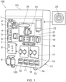
- Fig 1 shows a chromatography apparatus 100 according to an aspect of the invention.
- the apparatus includes, but it not limited to, individual modules 1 to 25 as listed below, at least some of which are demountable from an apertured front panel 120 of a housing 110 of the apparatus 100 and mounted thereon in one generally vertical plane, such that the liquid connections required between modules can be made only at the front face 120.
- the demountable modules have no more than two standard sizes which can, if needed, be repositioned on the panel 120 to suit a different procedure.
- Each module has a serial bus communication connection and power connection so that its physical position is immaterial to a controller for example located in the housing 110, or located remotely. Thereby, the modules can be regarded as modular and thereby repositionable and/or interchangeable.
- the chromatography apparatus shown in Figure 1 has the following module modules:
- Modules can be omitted or repositioned as explained above. It will be apparent that some modules can be replaced with other modules or the space left by an omitted module can be filled with a blanking plate (see e.g. 26 Fig 4 ). More than one of the same numbered modules can be used where necessary.
- Fluid interconnections between the fluid manipulating modules of the apparatus i.e. all the modules listed above except modules 1,15 and 23, and external modules for example sample input reservoirs, buffer fluid reservoirs, chromatograph column(s) and fraction collection equipment, all not shown in Figure 1 are made via fluid conduits in this case in the form of flexible plastics tubing, which can be readily coupled and uncoupled to corresponding ports of the fluid manipulating modules, in any desired configuration, for example using a coupling as disclosed in a related application WO 2019/002515 .
- Figure 2 shows one possible liquid interconnection configuration between the main modular modules of the chromatography apparatus, connected in this case to two chromatography columns 200 and 300, although the apparatus allows any workable interconnection between modules and additional parts such as multiple columns, and liquid reservoirs.
- Reconfigurable liquid interconnections are denoted by short chain dotted lines 80.
- the column valve 8 At the heart of the apparatus 100 is the column valve 8, which in this case has a construction as disclosed in our co-pending patent application filed on the same day as this application, and having the title 'VALVE UNIT FOR A CHROMATOGRAPHY APPARATUS.'
- the value unit 8 provides multiple switching of flow for allowing flow in one or both columns 200/300 in either direction (up or down in the drawing). The user can select upflow or downflow, or select to bypass one or both columns. The flow can be directed to waste or to the next component in the flow path.
- the columns can also be connected in series.
- the Column valve includes pre-column and post-column pressure sensors.
- valve has a port 150 which can be used to change the volume of hydraulic cylinders 210 and 310 which are part of the columns 200 and 300, for example to provide compression of the columns' contents, also known as column packing. That packing procedure can be automated. With such a system column diameters of between about 25 and 250 mm have been found to be packable in this way.
- the columns can be pre-packed, but rinsed and re-consolidated with the aid of pressure sensors in the value unit 8 measuring back-pressure resulting from pressure within the columns and in accordance with to known protocols, for example as described in WO 2007/045491 .
- the remaining system 100 comprises: Inlet valve groups A and B, 10,11,12 and 13, suitable for providing selectable liquids including sample containing liquids buffer solutions, and cleansing fluids.
- the inlet valves supply two system pumps, here each having a pair of pistons and associated one-way valves, providing a variable flow rate of between 0-600 ml per minute each (1200ml/min max), with a high volume and resolution of flow, enabling accurate flow rates to be maintained. Such accuracy enables good repeatability of results for a wide range of column diameters.
- the pumps supply, in series a flow restrictor 18, which includes a system pressure monitor, a mixer valve 20, and a mixer module 19, before pumped liquid is diverted to the column valve unit 8.
- Any entrained air can escape via an air trap valve 21, and an air trap vent 22, which vent also has an air escape from the columns 200 and 300.
- the air trap may be constructed in accordance with pending application WO 2019/043188 .
- Output from the chromatography column(s) is passed out through port 220 to: a conductivity monitor 5, a UV light absorption monitor 25, and a pH monitor 2, and is thence directed into an appropriate storage vessel in dependence on the signals from the three monitors, and thereby, separated fractions are collected in an appropriate vessel 501.
- Column washings can be collected in a waste vessel 500.
- the long chain dotted lines in Figure 2 represent a system bus 500 which carries signals and power to and from the modules mentioned above, to and from a controller 600. It will be appreciated that controlling and monitoring signals may be transmitted wirelessly according to known protocols, doing away with the need for a communication bus.
- the chromatography system 100 includes also a display screen 30. Software running on the controller will display plural icons on the screen 30 and allow user manipulation of the icon on the screen to drag and drop the icons to form a series of icons representative of a user defined chromatography control method, for ease of use.
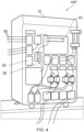
- FIGs 3 , 4 and 5 show the system connected with tubing for various configurations, where only some of the modules referenced in Figure 1 remain in place in these figures, and the apertures left by removed modules are blanked off with blanking plates 26, screwed into place over the aperture to prevent accidental liquid ingress into the housing 110.
- FIG 3 a system 100' with a configuration of modules suitable for regulated environments where systems are custom-built in a factory. The system is delivered mounted, calibrated, and performance tested and suitable for work in GMP environments.
- Figure 4 shows one system with some modules removed, and
- Figure 5 shows a system 100′′′ with more modules in place, similar to Figure 1 , and showing typical tubular interconnections 80.
- modules are easily removed or added to the system and installation finalized through a one-click activation in software which can recognize each module.
- the software can provide comprehensive and customizable operational control as well as pre-emptive maintenance.
- input-output communication modules can be used to interface with analog and/or digital external sensors or other equipment such as automatic fraction collecting devices.
- the wide flow rate and pressure ranges enables more than 40-fold scaling in the range 25 to 250 mm internal diameter columns. This wide range makes the apparatus suitable to bridge the transition into GMP environments.
- the packing (and re-packing) of chromatography columns, using the system described above is controllable fully by the controller 600 initiated by the control panel 1.
- the controller 600 is able to drive the a display screen 30 ( Fig 2 ) to aid visualisation of the packing process and progress.
- the control software includes an accessible column packing record. Columns packing records can therefore be defined, created, and updated from the software for traceability and quality assurance purposes. In addition, the record can be used to monitor column performance and provide statistics for usage, separation performance, and packing intervals.
- the display screen can provide a process visualization which quickly gives an operator an overview of the system's function, progress through operational steps and alarms, only providing the desired amount of information at each step.
- the active flow path is always displayed in the process visualisation to minimize user errors. Real time changes can be made by selecting the appropriate process on the visualization screen, e.g. selecting or dragging icons on the screen.
- Control, graphical interfaces are provided for specific sections, such as the column valve 8.
- Preprogrammed steps are employed but these can be modified and saved as user-defined steps for added customization.
- the system described and illustrated above is designed for sanitary environments.
- the system chassis 110 is flat or curved without joints, gaps or significant concavities, other than at the edges of the faces, which makes it easy to wipe down and reduces the chance of dust and liquid trapping.
- the pH monitor 2 has in-line calibration and the column valve 8 provides in-process column packing, so a closed flow path through operations can be employed, meaning that no breaks in the fluid path need be made throughout one or more chromatography column packing/regeneration stages and throughout the separation operation.
Landscapes
- Life Sciences & Earth Sciences (AREA)
- Physics & Mathematics (AREA)
- Health & Medical Sciences (AREA)
- Chemical & Material Sciences (AREA)
- Analytical Chemistry (AREA)
- Biochemistry (AREA)
- General Health & Medical Sciences (AREA)
- General Physics & Mathematics (AREA)
- Immunology (AREA)
- Pathology (AREA)
- Sustainable Development (AREA)
- Treatment Of Liquids With Adsorbents In General (AREA)
Claims (15)
- Chromatografiesystem (100) zum Trennen von Molekülmischungen in flüssigen Proben, umfassend:
eine Vielzahl von Modulen (1 ... 25) einschließlich mindestens einer Pumpe (16, 17) und einer Säulenventileinheit (8), die mit mehreren Chromatografiesäulen (200, 300) verbindbar ist; und gekennzeichnet durch:
eine Steuereinheit (600), wobei die Steuereinheit (600) betreibbar ist, um die oder jede Pumpe (16, 17) und die Säulenventileinheit (8) zu steuern, um verschiedene chromatographische Prozesse durchzuführen, einschließlich der Chromatografie, die nur eine Säule (200, 300) einsetzt, sowie der Chromatografie, die durch selektive Ventilöffnung in der Säulenventileinheit (8) zwei oder mehr Säulen (200, 300) einsetzt; wobei:
mindestens eines der Vielzahl von Modulen (1 ... 25) von einer mit Öffnungen versehenen Frontplatte (120) eines Gehäuses (110) des Chromatografiesystems (100) demontierbar und daran in einer allgemein vertikalen Ebene angebracht ist, so dass die erforderlichen Flüssigkeitsverbindungen zwischen den jeweiligen Modulen (1...25) nur an einer Vorderseite (120) des Chromatografiesystems (100) hergestellt werden können, wobei die Steuereinheit (600) weiter betreibbar ist, um eines oder mehrere von Säulenpackung, Säulenpackungstest und Reinigung von mindestens einem Teil des Chromatografiesystems (100) durchzuführen. - Chromatografiesystem (100) nach Anspruch 1, wobei die selektive Ventilöffnung eine Umkehrung der Strömungsrichtungen im Gebrauch in einer oder mehreren der mehreren Chromatografiesäulen (200, 300) ermöglicht.
- Chromatografiesystem (100) nach Anspruch 1 oder Anspruch 2, wobei die Steuereinheit (600) betreibbar ist, um die Module gemäß einer Software zu steuern, und einen Anzeigebildschirm (30), wobei die Software geeignet ist, mehrere Icons auf dem Bildschirm (30) anzuzeigen und eine Benutzermanipulation des Icons auf dem Bildschirm zu ermöglichen, um die Icons zu ziehen und abzulegen, um eine Reihe von Icons zu bilden, die ein benutzerdefiniertes Chromatografie-Steuerverfahren darstellen.
- Chromatografiesystem (100) nach Anspruch 3, wobei das benutzerdefinierte Verfahren einen kontinuierlichen Chromatografieprozess unter Einsatz der zwei oder mehr Chromatografiesäulen (200, 300) einschließt.
- Chromatografiesystem (100) nach einem der vorstehenden Ansprüche, wobei jedes demontierbare Modul (1...25) jeweils einen seriellen Bus-Kommunikationsanschluss und einen Stromanschluss umfasst.
- Chromatografiesystem (100) nach einem der vorstehenden Ansprüche, weiter umfassend mehrere Chromatografiesäulen (200, 300), wobei jede Säule eine Kammer mit veränderbarem Volumen zur Aufnahme von chromatographischen Trennmedien und einen Adapter, der zur Vergrößerung oder Verkleinerung jedes Volumens beweglich ist, einschließt, und wobei die Säulenventileinheit (8) in Fluidverbindung mit jedem der Adapter steht und selektiv betätigbar ist, um jeden der Adapter unabhängig oder gemeinsam mittels Fluiddruckänderungen zu bewegen, um folglich jedes der Volumina zu verändern und im Gebrauch eine Kompression oder eine Entlastung von der Kompression von Medien innerhalb jedes der Säulenvolumen zu bewirken.
- Chromatografiesystem (100) nach einem der vorstehenden Ansprüche, wobei die mehreren Module (1 ... 25) austauschbar in Öffnungen einer im Allgemeinen vertikalen Fläche (120) des Systemgehäuses (110) montierbar sind, wobei die Module für eine selektive fluidische Verbindung durch Schläuche angepasst sind, und wobei mindestens eines der Module die Säulenventileinheit (8) einschließt.
- Chromatografiesystem (100) nach Anspruch 7, wobei die Module (1...25) für eine selektive fluidische Verbindung durch Schläuche im Wesentlichen an der einen im Allgemeinen vertikalen Fläche (120) angepasst sind, so dass die Module und Schläuche im Gebrauch ein im Allgemeinen sich vertikal erstreckendes Volumen einnehmen, um die Grundfläche des Systems zu minimieren.
- Chromatografiesystem (100) nach Anspruch 7 oder 8, wobei das Systemgehäuse (110) anders als die eine im Allgemeinen vertikale Fläche (120) flache oder gekrümmte Flächen ohne andere Verbindungen als an den Kanten der Flächen aufweist.
- Chromatografiesystem (100) nach einem der vorstehenden Ansprüche, wobei die Module (1...25) eines oder mehrere umfassen von: einem pH-Monitor (2); einem Auslassventil (7, 9); einem Leitfähigkeitsmonitor (5); einem Säulenventil (8); einem Einlassventil (A1-A3, A4-A6, B1-B3, B4-B6); einer Systemflüssigkeitspumpe (16, 17); einem Durchflussbegrenzer (18); einem Mischer (19); einer Luftfalle (22); einem Luftfallenventil (21); und einer Luftfallenentlüftung (22) und einem UV-Monitor (25).
- Chromatografiesystem (100) nach Anspruch 10, wobei die Ausgabe von der/den Chromatografiesäule(n) (200, 300) durch einen Anschluss (220) zu einem Leitfähigkeitsmonitor (5), einem UV-Lichtabsorptionsmonitor (25) und einem pH-Monitor (2) geleitet wird und von dort in Abhängigkeit von den Signalen der drei Monitore (2, 5, 25) in ein geeignetes Speichergefäß (501) geleitet wird, so dass die getrennten Fraktionen in einem geeigneten Gefäß (501) gesammelt werden.
- Chromatografiesystem (100) nach Anspruch 11, wobei die Ausgabe der Säulenwaschungen in einem Abfallgefäß (500) gesammelt wird.
- Chromatografiesystem (100) nach einem der vorstehenden Ansprüche, wobei das System zwei Flüssigkeitspumpen (16, 17)) einschließt, wobei eine der Pumpen (16, 17) selektiv allein betreibbar ist oder beide Pumpen (16, 17) selektiv zusammen betreibbar sind, um dadurch einen Durchflussbereich bereitzustellen, der für mehr als eine Art von Chromatografieprozess geeignet ist.
- Chromatografiesystem (100) nach einem der vorstehenden Ansprüche, weiter umfassend einen Vorsäulen-Leitfähigkeitsmonitor (7) und/oder verstellbare Füße (15).
- Chromatografiesystem (100) nach einem der vorstehenden Ansprüche, wobei die Säulenventileinheit (8) weiter einen Anschluss (150) umfasst, der zur Änderung des Volumens von Hydraulikzylindern (210, 310) verwendet werden kann, um eine Kompression der Inhalte der Säulen (200, 300) bereitzustellen.
Priority Applications (1)
| Application Number | Priority Date | Filing Date | Title |
|---|---|---|---|
| EP25151578.9A EP4534995A3 (de) | 2017-09-22 | 2018-09-21 | Chromatographievorrichtung |
Applications Claiming Priority (2)
| Application Number | Priority Date | Filing Date | Title |
|---|---|---|---|
| GBGB1715403.0A GB201715403D0 (en) | 2017-09-22 | 2017-09-22 | Chromatography apparatus |
| PCT/EP2018/075693 WO2019057936A2 (en) | 2017-09-22 | 2018-09-21 | CHROMATOGRAPHY APPARATUS |
Related Child Applications (2)
| Application Number | Title | Priority Date | Filing Date |
|---|---|---|---|
| EP25151578.9A Division-Into EP4534995A3 (de) | 2017-09-22 | 2018-09-21 | Chromatographievorrichtung |
| EP25151578.9A Division EP4534995A3 (de) | 2017-09-22 | 2018-09-21 | Chromatographievorrichtung |
Publications (3)
| Publication Number | Publication Date |
|---|---|
| EP3685156A2 EP3685156A2 (de) | 2020-07-29 |
| EP3685156B1 true EP3685156B1 (de) | 2025-05-07 |
| EP3685156C0 EP3685156C0 (de) | 2025-05-07 |
Family
ID=60244509
Family Applications (2)
| Application Number | Title | Priority Date | Filing Date |
|---|---|---|---|
| EP25151578.9A Pending EP4534995A3 (de) | 2017-09-22 | 2018-09-21 | Chromatographievorrichtung |
| EP18779604.0A Active EP3685156B1 (de) | 2017-09-22 | 2018-09-21 | Chromatografievorrichtung |
Family Applications Before (1)
| Application Number | Title | Priority Date | Filing Date |
|---|---|---|---|
| EP25151578.9A Pending EP4534995A3 (de) | 2017-09-22 | 2018-09-21 | Chromatographievorrichtung |
Country Status (6)
| Country | Link |
|---|---|
| US (2) | US11740210B2 (de) |
| EP (2) | EP4534995A3 (de) |
| JP (1) | JP7330173B2 (de) |
| CN (2) | CN111094972B (de) |
| GB (1) | GB201715403D0 (de) |
| WO (1) | WO2019057936A2 (de) |
Families Citing this family (1)
| Publication number | Priority date | Publication date | Assignee | Title |
|---|---|---|---|---|
| GB202105909D0 (en) | 2021-04-26 | 2021-06-09 | Cytiva Sweden Ab | Gb2105909.2 |
Citations (1)
| Publication number | Priority date | Publication date | Assignee | Title |
|---|---|---|---|---|
| WO2010144037A1 (en) * | 2009-06-09 | 2010-12-16 | Ge Healthcare Bio-Sciences Ab | Automated fluid handling system |
Family Cites Families (23)
| Publication number | Priority date | Publication date | Assignee | Title |
|---|---|---|---|---|
| US3166929A (en) * | 1961-07-13 | 1965-01-26 | Technicon Chromatography Corp | Chromatography analysis apparatus with standardization provision |
| JPS5248516B1 (de) * | 1964-11-06 | 1977-12-10 | ||
| JPH07229885A (ja) * | 1994-02-16 | 1995-08-29 | Takeda Chem Ind Ltd | 試料の自動分離装置 |
| JP2000097924A (ja) * | 1998-09-18 | 2000-04-07 | Shimadzu Corp | 分析装置 |
| JP4228502B2 (ja) * | 2000-03-08 | 2009-02-25 | 株式会社島津製作所 | 液体クロマトグラフ及び流路切替バルブ |
| US7452471B2 (en) | 2005-10-21 | 2008-11-18 | Ge Healthcare Bio-Sciences Ab | Automated packing system and method for chromatography columns |
| BRPI0610795B8 (pt) * | 2005-05-20 | 2022-07-05 | Ge Healthcare Bio Sciences Ab | Sistema e método de recheio de colunas |
| US20070141720A1 (en) * | 2005-12-16 | 2007-06-21 | Stewart Larry N | Automated analysis of cations in acidic solutions |
| US7586102B2 (en) | 2006-08-14 | 2009-09-08 | Board Of Regents The University Of Texas System | Automated system for formulating radiopharmaceuticals |
| EP2682169B1 (de) * | 2007-03-06 | 2019-04-17 | GE Healthcare Bio-Sciences Corp. | Verfahren zur Automatisierung des Packens von Kolonnen |
| WO2008156484A1 (en) * | 2007-06-19 | 2008-12-24 | Neal Arnold | Apparatus, system, and method for low cost high resolution chemical detection |
| US8656955B2 (en) * | 2010-05-20 | 2014-02-25 | Bio-Rad Laboratories, Inc. | Rotary column selector valve |
| KR101120943B1 (ko) * | 2010-06-25 | 2012-03-05 | 고려대학교 산학협력단 | 다기능 선택밸브, 이를 포함하는 다기능 전자동 액체크로마토그래피 장치 및 이를 이용한 시료분석방법 |
| EP2632560B1 (de) * | 2010-10-29 | 2020-10-14 | Thermo Finnigan LLC | Modulare chromatographiekartusche mit mehreren säulen |
| US9304518B2 (en) * | 2011-08-24 | 2016-04-05 | Bio-Rad Laboratories, Inc. | Modular automated chromatography system |
| CN103907020B (zh) * | 2011-10-28 | 2017-10-13 | 萨默费尼根有限公司 | 用于液相色谱流体监控的方法和系统 |
| WO2015011522A1 (en) | 2013-07-23 | 2015-01-29 | Tubitak Ume | Multi-task sample preparation system with reconfigurable modules for on-line dilution, enzymatic digestion and fractionation |
| US20170010243A1 (en) * | 2014-02-11 | 2017-01-12 | Büchi Labortechnik AG | Multiple column chromatographic system and methods of use |
| CN105980847B (zh) * | 2014-02-14 | 2018-12-04 | 通用电气健康护理生物科学股份公司 | 自动多步纯化系统 |
| WO2016061558A1 (en) | 2014-10-16 | 2016-04-21 | Practichem Llc | Web-based interactive process facilities and systems management |
| CN107249709B (zh) * | 2014-12-18 | 2020-07-14 | 通用电气健康护理生物科学股份公司 | 基于压力探测的自动化层析柱切换控制 |
| JP6458504B2 (ja) * | 2015-01-14 | 2019-01-30 | 株式会社島津製作所 | 超臨界流体−液体クロマトグラフとその分析方法 |
| JP7097298B2 (ja) * | 2015-10-16 | 2022-07-07 | ロンザ リミテッド | 細胞培養に基づく生物製剤の生産を調節するためのシステムおよび方法 |
-
2017
- 2017-09-22 GB GBGB1715403.0A patent/GB201715403D0/en not_active Ceased
-
2018
- 2018-09-21 EP EP25151578.9A patent/EP4534995A3/de active Pending
- 2018-09-21 CN CN201880061359.6A patent/CN111094972B/zh active Active
- 2018-09-21 US US16/647,983 patent/US11740210B2/en active Active
- 2018-09-21 EP EP18779604.0A patent/EP3685156B1/de active Active
- 2018-09-21 CN CN202410010914.XA patent/CN118033021A/zh active Pending
- 2018-09-21 WO PCT/EP2018/075693 patent/WO2019057936A2/en not_active Ceased
- 2018-09-21 JP JP2020516802A patent/JP7330173B2/ja active Active
-
2023
- 2023-07-11 US US18/350,588 patent/US20230349867A1/en active Pending
Patent Citations (1)
| Publication number | Priority date | Publication date | Assignee | Title |
|---|---|---|---|---|
| WO2010144037A1 (en) * | 2009-06-09 | 2010-12-16 | Ge Healthcare Bio-Sciences Ab | Automated fluid handling system |
Also Published As
| Publication number | Publication date |
|---|---|
| WO2019057936A2 (en) | 2019-03-28 |
| US11740210B2 (en) | 2023-08-29 |
| CN111094972B (zh) | 2024-01-09 |
| EP4534995A2 (de) | 2025-04-09 |
| US20200264140A1 (en) | 2020-08-20 |
| US20230349867A1 (en) | 2023-11-02 |
| CN111094972A (zh) | 2020-05-01 |
| CN118033021A (zh) | 2024-05-14 |
| GB201715403D0 (en) | 2017-11-08 |
| JP2020534542A (ja) | 2020-11-26 |
| JP7330173B2 (ja) | 2023-08-21 |
| EP3685156C0 (de) | 2025-05-07 |
| EP3685156A2 (de) | 2020-07-29 |
| WO2019057936A3 (en) | 2019-05-02 |
| EP4534995A3 (de) | 2025-06-18 |
Similar Documents
| Publication | Publication Date | Title |
|---|---|---|
| EP2675540B1 (de) | System und verfahren für biopolymer-chromatographie | |
| CN105203689B (zh) | 自动化流体处理系统 | |
| EP3218706B1 (de) | Verfahren zur bestimmung des einflusses von experimentellen prozessparametern bei einem flüssigkeitschromatographie-protokol | |
| JP3452936B2 (ja) | 高速液体クロマトグラフィー法および装置 | |
| EP2081660B1 (de) | Chromatographiesäulen, -systeme und -verfahren | |
| US8920645B2 (en) | Disposable chromatography valves and system | |
| DE202012013690U1 (de) | Modulares automatisiertes Chromatografiesystem | |
| US20210086101A1 (en) | Valve Manifolds for Simulated Moving Bed Chromatography | |
| EP3645927B1 (de) | Chromatographiesystem und verbindungsstücke dafür | |
| US20230349867A1 (en) | Chromatography Apparatus | |
| US10843104B2 (en) | System and process for biopolymer chromatography | |
| CN102258885B (zh) | 整体柱层析自动分离系统 | |
| KR20110114560A (ko) | 크로마토그래피 시스템용 용매 공급 시스템 및 제작 방법 및 이용 방법 | |
| CN116008416A (zh) | 液相色谱仪 | |
| EP4083620B1 (de) | Lc-system und verfahren mit säulenrückspülung | |
| CN220090560U (zh) | 一种可拓展的色谱分离纯化装置 | |
| CN223774366U (zh) | 基于切向流层析柱的层析系统 | |
| CN206262156U (zh) | 多柱色谱设备 | |
| CN119186021A (zh) | 一种可拓展的色谱分离纯化装置 | |
| CN119345749A (zh) | 基于切向流层析柱的层析系统及其使用方法 | |
| CN2648447Y (zh) | 一种低压液相色谱分离装置 | |
| JPS6214060A (ja) | クロマトグラフイ−装置 | |
| JP2008298173A (ja) | 流路切換装置 |
Legal Events
| Date | Code | Title | Description |
|---|---|---|---|
| STAA | Information on the status of an ep patent application or granted ep patent |
Free format text: STATUS: UNKNOWN |
|
| STAA | Information on the status of an ep patent application or granted ep patent |
Free format text: STATUS: THE INTERNATIONAL PUBLICATION HAS BEEN MADE |
|
| PUAI | Public reference made under article 153(3) epc to a published international application that has entered the european phase |
Free format text: ORIGINAL CODE: 0009012 |
|
| STAA | Information on the status of an ep patent application or granted ep patent |
Free format text: STATUS: REQUEST FOR EXAMINATION WAS MADE |
|
| 17P | Request for examination filed |
Effective date: 20200309 |
|
| AK | Designated contracting states |
Kind code of ref document: A2 Designated state(s): AL AT BE BG CH CY CZ DE DK EE ES FI FR GB GR HR HU IE IS IT LI LT LU LV MC MK MT NL NO PL PT RO RS SE SI SK SM TR |
|
| AX | Request for extension of the european patent |
Extension state: BA ME |
|
| RAP1 | Party data changed (applicant data changed or rights of an application transferred) |
Owner name: CYTIVA SWEDEN AB |
|
| DAV | Request for validation of the european patent (deleted) | ||
| DAX | Request for extension of the european patent (deleted) | ||
| STAA | Information on the status of an ep patent application or granted ep patent |
Free format text: STATUS: EXAMINATION IS IN PROGRESS |
|
| 17Q | First examination report despatched |
Effective date: 20221027 |
|
| P01 | Opt-out of the competence of the unified patent court (upc) registered |
Effective date: 20230526 |
|
| GRAP | Despatch of communication of intention to grant a patent |
Free format text: ORIGINAL CODE: EPIDOSNIGR1 |
|
| STAA | Information on the status of an ep patent application or granted ep patent |
Free format text: STATUS: GRANT OF PATENT IS INTENDED |
|
| INTG | Intention to grant announced |
Effective date: 20241021 |
|
| GRAJ | Information related to disapproval of communication of intention to grant by the applicant or resumption of examination proceedings by the epo deleted |
Free format text: ORIGINAL CODE: EPIDOSDIGR1 |
|
| STAA | Information on the status of an ep patent application or granted ep patent |
Free format text: STATUS: EXAMINATION IS IN PROGRESS |
|
| INTC | Intention to grant announced (deleted) | ||
| GRAP | Despatch of communication of intention to grant a patent |
Free format text: ORIGINAL CODE: EPIDOSNIGR1 |
|
| STAA | Information on the status of an ep patent application or granted ep patent |
Free format text: STATUS: GRANT OF PATENT IS INTENDED |
|
| INTG | Intention to grant announced |
Effective date: 20250224 |
|
| GRAS | Grant fee paid |
Free format text: ORIGINAL CODE: EPIDOSNIGR3 |
|
| GRAA | (expected) grant |
Free format text: ORIGINAL CODE: 0009210 |
|
| STAA | Information on the status of an ep patent application or granted ep patent |
Free format text: STATUS: THE PATENT HAS BEEN GRANTED |
|
| AK | Designated contracting states |
Kind code of ref document: B1 Designated state(s): AL AT BE BG CH CY CZ DE DK EE ES FI FR GB GR HR HU IE IS IT LI LT LU LV MC MK MT NL NO PL PT RO RS SE SI SK SM TR |
|
| REG | Reference to a national code |
Ref country code: GB Ref legal event code: FG4D |
|
| REG | Reference to a national code |
Ref country code: CH Ref legal event code: EP |
|
| REG | Reference to a national code |
Ref country code: DE Ref legal event code: R096 Ref document number: 602018081754 Country of ref document: DE |
|
| REG | Reference to a national code |
Ref country code: IE Ref legal event code: FG4D |
|
| U01 | Request for unitary effect filed |
Effective date: 20250604 |
|
| U07 | Unitary effect registered |
Designated state(s): AT BE BG DE DK EE FI FR IT LT LU LV MT NL PT RO SE SI Effective date: 20250611 |
|
| P04 | Withdrawal of opt-out of the competence of the unified patent court (upc) registered |
Free format text: CASE NUMBER: APP_26969/2025 Effective date: 20250606 |
|
| REG | Reference to a national code |
Ref country code: CH Ref legal event code: U11 Free format text: ST27 STATUS EVENT CODE: U-0-0-U10-U11 (AS PROVIDED BY THE NATIONAL OFFICE) Effective date: 20251001 |
|
| PG25 | Lapsed in a contracting state [announced via postgrant information from national office to epo] |
Ref country code: ES Free format text: LAPSE BECAUSE OF FAILURE TO SUBMIT A TRANSLATION OF THE DESCRIPTION OR TO PAY THE FEE WITHIN THE PRESCRIBED TIME-LIMIT Effective date: 20250507 |
|
| PG25 | Lapsed in a contracting state [announced via postgrant information from national office to epo] |
Ref country code: NO Free format text: LAPSE BECAUSE OF FAILURE TO SUBMIT A TRANSLATION OF THE DESCRIPTION OR TO PAY THE FEE WITHIN THE PRESCRIBED TIME-LIMIT Effective date: 20250807 Ref country code: GR Free format text: LAPSE BECAUSE OF FAILURE TO SUBMIT A TRANSLATION OF THE DESCRIPTION OR TO PAY THE FEE WITHIN THE PRESCRIBED TIME-LIMIT Effective date: 20250808 |
|
| PG25 | Lapsed in a contracting state [announced via postgrant information from national office to epo] |
Ref country code: PL Free format text: LAPSE BECAUSE OF FAILURE TO SUBMIT A TRANSLATION OF THE DESCRIPTION OR TO PAY THE FEE WITHIN THE PRESCRIBED TIME-LIMIT Effective date: 20250507 |
|
| PGFP | Annual fee paid to national office [announced via postgrant information from national office to epo] |
Ref country code: GB Payment date: 20250923 Year of fee payment: 8 |
|
| PG25 | Lapsed in a contracting state [announced via postgrant information from national office to epo] |
Ref country code: HR Free format text: LAPSE BECAUSE OF FAILURE TO SUBMIT A TRANSLATION OF THE DESCRIPTION OR TO PAY THE FEE WITHIN THE PRESCRIBED TIME-LIMIT Effective date: 20250507 |
|
| PG25 | Lapsed in a contracting state [announced via postgrant information from national office to epo] |
Ref country code: RS Free format text: LAPSE BECAUSE OF FAILURE TO SUBMIT A TRANSLATION OF THE DESCRIPTION OR TO PAY THE FEE WITHIN THE PRESCRIBED TIME-LIMIT Effective date: 20250807 |
|
| PG25 | Lapsed in a contracting state [announced via postgrant information from national office to epo] |
Ref country code: IS Free format text: LAPSE BECAUSE OF FAILURE TO SUBMIT A TRANSLATION OF THE DESCRIPTION OR TO PAY THE FEE WITHIN THE PRESCRIBED TIME-LIMIT Effective date: 20250907 |
|
| U20 | Renewal fee for the european patent with unitary effect paid |
Year of fee payment: 8 Effective date: 20250925 |
|
| PG25 | Lapsed in a contracting state [announced via postgrant information from national office to epo] |
Ref country code: SM Free format text: LAPSE BECAUSE OF FAILURE TO SUBMIT A TRANSLATION OF THE DESCRIPTION OR TO PAY THE FEE WITHIN THE PRESCRIBED TIME-LIMIT Effective date: 20250507 |
|
| PGFP | Annual fee paid to national office [announced via postgrant information from national office to epo] |
Ref country code: CH Payment date: 20251001 Year of fee payment: 8 |
|
| PG25 | Lapsed in a contracting state [announced via postgrant information from national office to epo] |
Ref country code: CZ Free format text: LAPSE BECAUSE OF FAILURE TO SUBMIT A TRANSLATION OF THE DESCRIPTION OR TO PAY THE FEE WITHIN THE PRESCRIBED TIME-LIMIT Effective date: 20250507 |
|
| PG25 | Lapsed in a contracting state [announced via postgrant information from national office to epo] |
Ref country code: SK Free format text: LAPSE BECAUSE OF FAILURE TO SUBMIT A TRANSLATION OF THE DESCRIPTION OR TO PAY THE FEE WITHIN THE PRESCRIBED TIME-LIMIT Effective date: 20250507 |
|
| PLBE | No opposition filed within time limit |
Free format text: ORIGINAL CODE: 0009261 |
|
| STAA | Information on the status of an ep patent application or granted ep patent |
Free format text: STATUS: NO OPPOSITION FILED WITHIN TIME LIMIT |
|
| REG | Reference to a national code |
Ref country code: CH Ref legal event code: L10 Free format text: ST27 STATUS EVENT CODE: U-0-0-L10-L00 (AS PROVIDED BY THE NATIONAL OFFICE) Effective date: 20260318 |
|
| 26N | No opposition filed |
Effective date: 20260210 |