EP3682712B1 - Haushaltsgerät mit temperaturdetektor - Google Patents
Haushaltsgerät mit temperaturdetektor Download PDFInfo
- Publication number
- EP3682712B1 EP3682712B1 EP18762492.9A EP18762492A EP3682712B1 EP 3682712 B1 EP3682712 B1 EP 3682712B1 EP 18762492 A EP18762492 A EP 18762492A EP 3682712 B1 EP3682712 B1 EP 3682712B1
- Authority
- EP
- European Patent Office
- Prior art keywords
- temperature
- detector
- transistor
- household microwave
- microwave appliance
- Prior art date
- Legal status (The legal status is an assumption and is not a legal conclusion. Google has not performed a legal analysis and makes no representation as to the accuracy of the status listed.)
- Active
Links
Images

Classifications
-
- H—ELECTRICITY
- H05—ELECTRIC TECHNIQUES NOT OTHERWISE PROVIDED FOR
- H05B—ELECTRIC HEATING; ELECTRIC LIGHT SOURCES NOT OTHERWISE PROVIDED FOR; CIRCUIT ARRANGEMENTS FOR ELECTRIC LIGHT SOURCES, IN GENERAL
- H05B6/00—Heating by electric, magnetic or electromagnetic fields
- H05B6/64—Heating using microwaves
- H05B6/66—Circuits
- H05B6/68—Circuits for monitoring or control
- H05B6/686—Circuits comprising a signal generator and power amplifier, e.g. using solid state oscillators
-
- H—ELECTRICITY
- H05—ELECTRIC TECHNIQUES NOT OTHERWISE PROVIDED FOR
- H05B—ELECTRIC HEATING; ELECTRIC LIGHT SOURCES NOT OTHERWISE PROVIDED FOR; CIRCUIT ARRANGEMENTS FOR ELECTRIC LIGHT SOURCES, IN GENERAL
- H05B6/00—Heating by electric, magnetic or electromagnetic fields
- H05B6/64—Heating using microwaves
- H05B6/6447—Method of operation or details of the microwave heating apparatus related to the use of detectors or sensors
- H05B6/645—Method of operation or details of the microwave heating apparatus related to the use of detectors or sensors using temperature sensors
- H05B6/6455—Method of operation or details of the microwave heating apparatus related to the use of detectors or sensors using temperature sensors the sensors being infrared detectors
-
- G—PHYSICS
- G01—MEASURING; TESTING
- G01J—MEASUREMENT OF INTENSITY, VELOCITY, SPECTRAL CONTENT, POLARISATION, PHASE OR PULSE CHARACTERISTICS OF INFRARED, VISIBLE OR ULTRAVIOLET LIGHT; COLORIMETRY; RADIATION PYROMETRY
- G01J5/00—Radiation pyrometry, e.g. infrared or optical thermometry
- G01J5/0096—Radiation pyrometry, e.g. infrared or optical thermometry for measuring wires, electrical contacts or electronic systems
-
- G—PHYSICS
- G01—MEASURING; TESTING
- G01J—MEASUREMENT OF INTENSITY, VELOCITY, SPECTRAL CONTENT, POLARISATION, PHASE OR PULSE CHARACTERISTICS OF INFRARED, VISIBLE OR ULTRAVIOLET LIGHT; COLORIMETRY; RADIATION PYROMETRY
- G01J5/00—Radiation pyrometry, e.g. infrared or optical thermometry
- G01J5/02—Constructional details
- G01J5/03—Arrangements for indicating or recording specially adapted for radiation pyrometers
-
- G—PHYSICS
- G01—MEASURING; TESTING
- G01J—MEASUREMENT OF INTENSITY, VELOCITY, SPECTRAL CONTENT, POLARISATION, PHASE OR PULSE CHARACTERISTICS OF INFRARED, VISIBLE OR ULTRAVIOLET LIGHT; COLORIMETRY; RADIATION PYROMETRY
- G01J5/00—Radiation pyrometry, e.g. infrared or optical thermometry
- G01J5/10—Radiation pyrometry, e.g. infrared or optical thermometry using electric radiation detectors
-
- H—ELECTRICITY
- H05—ELECTRIC TECHNIQUES NOT OTHERWISE PROVIDED FOR
- H05B—ELECTRIC HEATING; ELECTRIC LIGHT SOURCES NOT OTHERWISE PROVIDED FOR; CIRCUIT ARRANGEMENTS FOR ELECTRIC LIGHT SOURCES, IN GENERAL
- H05B6/00—Heating by electric, magnetic or electromagnetic fields
- H05B6/64—Heating using microwaves
- H05B6/66—Circuits
- H05B6/666—Safety circuits
Definitions
- the invention relates to a household appliance which has at least one circuit component, a control device for controlling the at least one circuit component and a temperature detector which is coupled to the control device.
- the invention also relates to a method for operating such a household appliance.
- the invention is particularly advantageously applicable to microwave cooking devices such as stand-alone microwave cooking devices or ovens, e.g. ovens, with microwave functionality.
- Previously known semiconductor amplifiers in microwave cooking devices use a feedthrough network that is connected downstream of at least one transistor.
- the semiconductor amplifier has, among other things, a circulator to protect the transistor from microwave power reflected back from a cooking chamber, a unit for detecting or measuring the reflected microwave power and an end load for dissipating the reflected microwave power.
- DE 298 039 05 U1 discloses a hob for measuring the temperature of cookware, with a hob frame on which a sensor assembly is mounted, which has a receiving part fastened below the hob frame and a tubular sensor part guided vertically displaceably in this with a viewing window through which, when the sensor part is extended upwards through a frame opening, heat radiation falls on an infrared sensor arranged in the sensor part, whereby a contactless measurement of the wall temperature of a heat-radiating cooking appliance placed on the hob is possible.
- DE 10 305 368 A1 discloses an electric motor having a plurality of components such as stator, rotor, windings and bearings, whose operation-dependent temperatures are monitored, wherein these components have temperature sensors for determining their absolute temperatures.
- the temperature sensors are thermal radiation sensors that enable contactless detection and/or measurement of the radiated heat.
- WO 2015/037004 A1 concerns the measurement of the temperature of objects under strong electromagnetic fields.
- US 5 645 748 A relates to a method and a system for simultaneously sterilizing a plurality of metallic surgical instruments by means of microwave radiation and for preventing arcing of the metallic surgical instruments.
- US 2010/115785 A1 generally deals with drying an object, optionally using RF energy.
- the object is clothing.
- EP 2 182 774 A1 t relates to a microwave heating device for heating an object to be heated, ie a heating target, by irradiation with a microwave.
- US 4 996 403 A refers generally to the art of microwave heating control systems and, in particular, to the control of the boiling process of a liquid in a microwave applicator.
- US 2003/121913 A1 relates to a microwave heating appliance, and more particularly to a microwave heating appliance having a microwave heating element mounted on the surface of a hotplate on which food is placed in a heating chamber.
- GB 2 310 733 A relates to a heat control system for a microwave oven suitable for heating packaged food sealed with a lid or plastic film.
- WO 2004/091260 A1 concerns a high frequency heating device.
- US 2013/278345 A1 refers generally to electronic circuits and particularly to microwave adapters for solid-state microwave oscillators.
- US 5 021 620 A relates to a high-frequency heating apparatus in which a direct current voltage obtained by rectifying a high-frequency voltage generated by an inverter circuit in a rectifier circuit is applied to a magnetron and thereby drives the magnetron, and more particularly to such a high-frequency heating apparatus provided with compensating means for compensating an anode current of the magnetron to maintain it at a predetermined value.
- US 5 389 335 A relates to a system and method for heating to high temperatures and for short periods of time, and more particularly to a system and method for heating to high temperatures and for short periods of time for heat-sensitive material that preserves the selected biological properties of the heat-sensitive material while achieving a multiple log reduction of pathogens, such as viruses, in the heat-sensitive material.
- a household appliance comprising at least one circuit component, a control device for controlling the at least one circuit component and at least one temperature detector for sensing a temperature of at least one circuit component, wherein the control device is coupled to the temperature detector and is configured to control the household appliance based on temperature measurement data measured by the temperature detector, and wherein the at least one temperature detector is an IR detector.
- Temperature-critical operation can include, for example, operation after a component limit temperature has been exceeded or an excessively rapid temperature rise.
- IR detector in particular has the advantage of achieving a particularly high detection speed and precision in temperature measurement, since thermal inertia plays practically no role. This in turn enables the monitored circuit component to be controlled particularly quickly and/or precisely to adjust its temperature.
- thermocouples such as platinum measuring resistors or similar can interfere with this circuit component if they touch the circuit component or are located close to it.
- the connecting leads of contacting thermocouples can also disadvantageously couple out a signal.
- thermocouples also have a higher thermal inertia than an IR detector, especially if the thermocouple has to be arranged at a distance from the circuit component to be sensed. In particular, if the thermocouple has to be arranged at a distance from the circuit component to be sensed in order not to disturb it, thermocouples do not allow for sufficiently accurate and delay-free temperature measurement of the circuit component and thus also do not allow for sufficiently fast response to thermal overload of the component.
- the household appliance can be a household cooking appliance.
- the at least one circuit component that can be sensed or detected is therefore located in the field of view of the IR detector.
- the IR detector can sense exactly one circuit component or several circuit components.
- exactly one circuit component or several circuit components can be located in the field of view or detector area of the IR detector.
- the household appliance can have one or more IR detectors.
- At least one IR detector is a spatially non-resolving IR detector.
- Such an IR detector is particularly inexpensive and robust and is also particularly easy to evaluate.
- the IR detector is a spatially resolving IR detector. This has the advantage that additional information can be obtained and, in addition, several heat sources located in the field of view of the IR detector, e.g. comprising several circuit components, can be distinguished.
- the IR detector can have one or more IR sensors.
- the IR detector can have, for example, one or more thermopiles or thermochains as IR sensors.
- the IR detector can also be an IR-sensitive semiconductor chip, e.g. a CCD sensor.
- the IR detector can have an optical system connected upstream of the at least one IR sensor.
- the optical system can have, for example, at least one lens, at least one aperture, etc.
- circuit components are sensed by one or more IR detectors, an exact differentiation of the respective component temperatures is possible using assigned sensors.
- a temperature measurement with a thermocouple for example, no measurement error occurs due to the superposition of the temperatures of the various circuit components.
- asymmetrical thermal loads on the circuit components and, in particular, even the smallest errors in a particular component can be detected.
- an IR detector detecting image-by-image or pixel-by-pixel is designed and arranged to sense the temperature of several circuit components or several circuit components are located in the field of view or detector area of the IR detector that local temperature ranges can be assigned to respective circuit components in an image recorded by the IR detector.
- a circuit component can be understood as a component of a circuit or a circuit network.
- the circuit component can be an electrical or electronic component.
- the circuit component can be, for example, an ohmic resistor, a capacitor, a coil or the like.
- the circuit component can also be a semiconductor component.
- the circuit component can be an integrated circuit or have an integrated circuit.
- control device is designed to control at least one temperature-sensing circuit component based on temperature measurement data measured by the temperature detector.
- control device is designed to control at least one sensable circuit component based on temperature measurement data measured by the temperature detector can, in one embodiment, include that based on the occurrence of an event that can be determined by the temperature measurement data, at least one action is triggered or can be triggered by the household appliance.
- the occurrence of the event can include operation in a critical temperature range or an expected entry into the critical temperature range.
- the action can be an output a warning to a user and/or triggering at least one countermeasure to reduce the temperature.
- Setting up the control device may include programming it.
- At least one circuit component that can be sensed by the IR detector is a high-frequency (HF) circuit component.
- the IR detector can be used particularly advantageously here, since HF components are particularly strongly influenced by the presence of metallic objects in their vicinity.
- contacting thermocouples such as platinum measuring resistors or similar must be arranged at a distance from the HF circuit component to be sensed so as not to disturb it, e.g. on a heat sink of the circuit component. Consequently, due to the thermal inertia or the thermal resistance of the overall system with thermocouples, it is not possible to measure the temperature of an HF circuit component accurately and without delay, and thus also not to react sufficiently quickly to a thermal overload of the HF circuit component.
- At least one RF component is an RF transistor. It is another development that at least one circuit component is a part or component of an amplifier circuit.
- At least one circuit component is a part or a component of a feedthrough network.
- the feedthrough network can be connected downstream of the RF transistor.
- the feedthrough network can, together with the RF transistor, form part of the amplifier circuit or correspond to the amplifier circuit.
- the feedthrough network can, among other things, have a circulator for protecting the RF transistor, a unit for detecting the reflected microwave power (e.g. a directional coupler) and/or an end load for dissipating microwave power reflected back from a cooking chamber.
- the household appliance is a microwave device and the at least one RF component is a microwave component.
- the microwave device can have a magnetron to generate the microwaves.
- the microwave appliance can be a microwave cooking appliance.
- the microwave cooking appliance can have a cooking chamber into which microwaves can be fed in order to heat the food to be cooked therein.
- the microwave cooking appliance can be a stand-alone microwave cooking appliance.
- the microwave cooking appliance can alternatively be an oven, e.g. an oven, with microwave functionality.
- the microwave oven can also be a sterilizer for cooking dishes, etc.
- the IR detector has at least one IR sensor that is aligned with the at least one circuit component to be sensed. This advantageously enables a particularly simple and compact structure as well as a particularly distortion-free viewing of the field of view.
- the IR detector is spaced apart from the at least one circuit component to be sensed. This keeps the influence on this circuit component particularly low. This also allows a more flexible positioning of the IR detector.
- the fact that the IR detector is spaced apart from the at least one circuit component to be sensed includes in particular that there is a gap or a gap, in particular an air gap, between them. This gap provides particularly effective RF insulation between the at least one circuit component to be sensed and the IR detector, in particular for RF circuit components.
- the at least one temperature-sensing circuit component is housed in a shielding housing and the IR detector is arranged outside this housing.
- the IR detector is arranged outside this housing.
- electrical lines of the IR detector e.g. a data and/or power supply line
- electrical lines of the IR detector are arranged completely outside the housing and consequently no interference with the measurement and/or data transmission occurs due to high-frequency fields. This also makes it possible to avoid cable feedthroughs through the housing.
- the presence of electrical lines inside the housing which could also interfere with HF circuit components, can be avoided.
- the IR detector has at least one IR sensor and at least one IR optical waveguide, and IR light emitted by the at least one circuit component to be sensed falls through the IR optical waveguide onto the at least one IR sensor.
- the IR optical waveguide can in particular have one or more fiber optic cables.
- the IR optical waveguide touches at least one circuit component to be sensed by the IR detector. This allows a particularly precise temperature measurement to be achieved. Since the IR optical waveguide is not metallic, but consists of plastic or glass, for example, it does not interfere with the circuit component, in particular the RF circuit component.
- At least one action comprises a reduction in the power introduced into at least one senseable circuit component.
- the control device is alternatively or additionally set up to control at least one other circuit component in such a way that the power introduced into the at least one senseable circuit component is reduced or can be reduced.
- Reducing the power can be a reduction in electrical power and/or microwave power. Reducing the power can include the senseable circuit component only being operated at partial power or even being deactivated completely. Reducing the power is therefore a possible countermeasure for reducing the temperature of the senseable circuit component.
- the sensable circuit component is an HF circuit component and at least one action comprises a change in at least one HF parameter.
- the control device is therefore set up to change at least one HF parameter based on temperature measurement data of an HF circuit component measured by the temperature detector.
- the power of the reflected microwaves can be reduced, whereby the temperature in an HF circuit component - e.g. an HF transistor - can be reduced.
- An HF parameter can, for example, comprise an amplitude, a frequency and/or a phase offset of microwaves radiated into a cooking chamber.
- the Changing RF parameters may correspond to changing an operating point, so changing the RF parameters is another possible countermeasure to reduce the temperature of the sensed circuit component.
- the occurrence of the event that can be determined by the temperature measurement data includes a detection of a temperature-critical operation of at least one circuit component.
- the control device is therefore particularly designed to change the control of at least one senseable circuit component based on a detection of a (temperature-)critical operation of at least one circuit component. This makes it possible to prevent overheating and thus possible damage to the circuit component.
- the temperature-critical operation includes reaching or exceeding a predetermined threshold value by a temporal temperature gradient.
- the control device is therefore particularly designed to determine temperature-critical operation by a temporal temperature gradient reaching or exceeding a predetermined threshold value.
- the calculated temperature gradient it is advantageously possible to approximately determine reflected power, in particular microwave power reflected back from a cooking chamber. If the temperature gradient increases excessively quickly, the control of the household appliance can be changed so that the reflected power is reduced even before a critical temperature is reached on the monitored circuit component.
- the temporal temperature gradient can be used to detect or diagnose component aging, component drift and/or impermissible deviations from known operating states.
- the temperature-critical operation includes a temperature reaching or exceeding a predetermined threshold value.
- the control device is therefore set up to determine a temperature-critical operation by a temperature reaching or exceeding at least one predetermined threshold value.
- An overtemperature, a warning temperature and/or a critical limit temperature etc. can be determined on this circuit component using the IR detector.
- the control device can therefore be programmed in such a way that it detects, based on an instantaneous temperature value, a temperature profile and/or a temporal temperature gradient, whether the temperature-sensing component is in normal operation (without excessive/rapid heating) or in critical operation (with excessive/rapid heating).
- the household appliance is a microwave cooking appliance that has a semiconductor amplifier with an HF transistor and with a feedthrough network connected downstream of the HF transistor, that the temperature detector is arranged and set up to sense a temperature of at least the HF transistor and that the control device is set up to trigger at least one action based on the occurrence of an event that can be determined by the temperature measurement data, which leads to a reduction in a temperature on the HF transistor or which triggers a countermeasure to reduce the temperature on the HF transistor.
- the occurrence of the event can - as already described above - include, for example, an operation of the HF transistor in a critical temperature range or an expected entry of the HF transistor into the critical temperature range.
- This embodiment has the advantage that it is possible to react particularly quickly and reliably to a critical or critically becoming temperature increase of the HF transistor.
- monitoring the HF transistor using an IR detector makes it possible to dispense with a circulator, which was previously provided to protect the HF transistor.
- the end load can be dispensed with.
- a measuring device for measuring the reflected microwave radiation can be dispensed with.
- the feedthrough network can be dispensed with entirely. All of these developments result in high cost savings due to the elimination of components compared to only small additional costs due to the provision of the IR detector.
- losses due to the feedthrough network can be reduced, which leads to a higher level of efficiency.
- the microwave cooking appliance can be circulator-free and/or end load-free and/or free of a measuring device for measuring the reflected microwave radiation or completely free of a feedthrough network.
- the object is also achieved by a method for operating a household appliance, having at least one circuit component, a control device for controlling the at least one circuit component and at least one temperature detector for sensing a temperature of at least one circuit component, wherein the control device is coupled to the at least one temperature detector and wherein, in the method, a temperature of at least one circuit component is sensed by means of at least one IR detector as the at least one temperature detector and the control device controls the household appliance based on the sensed temperature.
- the method can be designed analogously to the household appliance and has the same advantages.
- Fig.1 shows a detail of a household appliance in the form of a microwave cooking appliance 1.
- the microwave cooking appliance 1 has a cooking chamber 2 which is enclosed by a cooking chamber wall 3. Outside the cooking chamber wall 3 - here: above a ceiling of the cooking chamber wall 3 - a housing 4 is arranged which encloses a HF area 5 in a shielding manner.
- a circuit component in the form of an HF transistor 6 which comprises part of an amplifier circuit for introducing microwaves into the cooking chamber 2.
- An IR detector 7 is arranged on an outside of the housing 4.
- the IR detector 7 is directed directly at the RF transistor 6 through a window 14 in the housing 4 and can sense or measure the temperature of the RF transistor 6.
- the IR detector 7 is therefore spaced apart from the RF transistor 6.
- the IR detector 7 can have at least one IR sensor 8.
- the IR detector 7 is coupled to a control device 9, by means of which the amplifier circuit, and possibly also the RF transistor 6 directly, can be controlled.
- the coupling can be made via a data cable 10.
- Temperature measurement data for example, is transmitted from the IR detector 7 to the control device 9 via the data cable 10.
- the control device 9 is set up to control the microwave cooking device 1 based on temperature measurement data measured by the IR detector 7.
- the control device 9 is set up to trigger at least one action based on the occurrence of an event that can be determined by the temperature measurement data.
- the at least one action can comprise a reduction in the power introduced into the RF transistor 6.
- the power can be understood in particular as the microwave power reflected back from the cooking chamber 2.
- the at least one action can alternatively or additionally comprise a change in at least one microwave parameter (such as an amplitude, a frequency and/or a phase shift of the microwaves radiated into the cooking chamber 2) which influence the reflected back power.
- the occurring event can include a detection of temperature-critical operation of at least one circuit component.
- the temperature-critical operation can include, for example, reaching or exceeding a predetermined threshold value by a temporal temperature gradient and/or reaching or exceeding a predetermined threshold value by an (instantaneous) temperature.
- the control device 9 is in particular designed to trigger at least one action based on the occurrence of an event that can be determined by the temperature measurement data sensed by the HF transistor 6, which leads to a reduction in the temperature at the HF transistor 6.
- the microwave cooking appliance 1 can thus react quickly to an impending or occurring overheating of the HF transistor 6 and take appropriate Take countermeasures.
- the amplifier circuit of the microwave cooking appliance 1 may possibly dispense with a circulator, an end load, a measuring device for measuring the reflected microwave radiation or even a feedthrough network altogether.
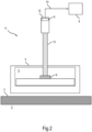
- Fig.2 shows a sectional side view of a section from a sketch of a microwave cooking device 11 according to the invention according to a second embodiment.
- the microwave cooking device 11 is designed similarly to the microwave cooking device 1, but now has an IR detector 12, at least one IR sensor 8 and at least one IR optical waveguide 13.
- the IR optical waveguide 13 extends through the window 14 into the HF area 5.
- the end face of the IR optical waveguide 13 that couples in IR light touches the RF transistor 6 (or at least has a very small gap thereto). IR light emitted by the RF transistor 6 is therefore guided through the IR optical waveguide 13 to the at least one IR sensor 8.
- This embodiment has the advantage of only very little measurement interference from other heat sources.
- the IR optical waveguide 13 is shown here as a straight line, it can also be curved.
- the IR sensor 8 does not then have to be aligned with the RF transistor 6, but it can be. This allows for a particularly diverse positioning of the IR sensor 8.
- a numerical value may also include the exact number stated as well as a usual tolerance range, as long as this is not explicitly excluded.
Landscapes
- Physics & Mathematics (AREA)
- General Physics & Mathematics (AREA)
- Spectroscopy & Molecular Physics (AREA)
- Electromagnetism (AREA)
- Electric Ovens (AREA)
- Control Of High-Frequency Heating Circuits (AREA)
Description
- Die Erfindung betrifft ein Haushaltsgerät, das mindestens ein Schaltungsbauteil, eine Steuereinrichtung zum Ansteuern des mindestens einen Schaltungsbauteils und einen Temperaturdetektor, der mit der Steuereinrichtung gekoppelt ist, aufweist. Die Erfindung betrifft auch ein Verfahren zum Betreiben eines solchen Haushaltsgeräts. Die Erfindung ist insbesondere vorteilhaft anwendbar auf Mikrowellen-Gargeräte wie eigenständige Mikrowellen-Gargeräte oder Öfen, z.B. Backöfen, mit Mikrowellenfunktionalität.
- Bisher bekannte Halbleiterverstärker in Mikrowellen-Gargeräten verwenden ein Durchführungsnetzwerk, das mindestens einem Transistor nachgeschaltet ist. Der Halbleiterverstärker weist unter anderem einen Zirkulator zum Schutz des Transistors vor aus einem Garraum zurückreflektierte Mikrowellen-Leistung, eine Einheit zur Erfassung oder Messung der reflektierten Mikrowellen-Leistung sowie eine Endlast zur Abführung der reflektierten Mikrowellen-Leistung auf.
-
DE 298 039 05 U1 offenbart zur Temperaturmessung von Kochgeschirr ein Kochfeld mit einem Kochfeldrahmen, an dem eine Sensorbaugruppe gehaltert ist, die ein unterhalb des Kochfeldrahmens befestigtes Aufnahmeteil und ein in diesem vertikal verschiebbar geführtes rohrförmiges Sensorteil mit einem Sichtfenster aufweist, durch das bei nach oben durch eine Rahmenöffnung ausgefahrenem Sensorteil Wärmestrahlung auf einen in dem Sensorteil angeordneten Infrarotsensor fällt, wodurch eine berührungslose Messung der Wandtemperatur eines auf dem Kochfeld abgestellten wärmeabstrahlenden Gargerätes möglich ist. -
DE 10 305 368 A1 offenbart einen Elektromotor, der mehrere Bauteile wie Stator, Rotor, Wicklungen und Lager aufweist, deren betriebsabhängige Temperaturen überwacht werden, wobei diese Komponenten Temperatursensoren zur Ermittlung ihrer absoluten Temperaturen aufweisen. Die Temperatursensoren sind Wärmestrahlungssensoren, die eine berührungslose Erfassung und / oder Messung der abgestrahlten Wärme ermöglichen. -
WO 2015/037004 A1 betrifft die Messung der Temperatur von Objekten unter starken elektromagnetischen Feldern. -
US 5 645 748 A betrifft ein Verfahren und ein System zum gleichzeitigen Sterilisieren einer Vielzahl metallischer chirurgischer Instrumente mittels Mikrowellenstrahlung und zur Verhinderung einer Lichtbogenbildung der metallischen chirurgischen Instrumente. -
US 2010/115785 A1 befasst sich im Allgemeinen mit dem Trocknen eines Objekts, optional unter Verwendung von HF-Energie. In vielen Ausführungsformen der Erfindung handelt es sich bei dem Objekt um Kleidung. -
EP 2 182 774 A1 t betrifft eine Mikrowellen-Heizvorrichtung zum Erhitzen eines zu erhitzenden Objekts, d. h. eines Heizziels, durch Bestrahlung mit einer Mikrowelle. -
US 4 996 403 A bezieht sich allgemein auf die Technik der Mikrowellen-Heizungssteuerungssysteme und insbesondere auf die Steuerung des Siedeprozesses einer Flüssigkeit in einem Mikrowellenapplikator. -
US 2003/121913 A1 bezieht sich auf ein Mikrowellen-Heizgerät und insbesondere auf ein Mikrowellen-Heizgerät mit einem Mikrowellen-Heizelement, das auf der Oberfläche einer Heizplatte montiert ist, auf die Nahrungsmittel in einer Heizkammer gelegt werden. -
GB 2 310 733 A -
WO 2004/091260 A1 betrifft ein Hochfrequenz-Heizgerät. -
US 2013/278345 A1 bezieht sich allgemein auf elektronische Schaltkreise und insbesondere auf Mikrowellenadapter für Festkörper-Mikrowellenoszillatoren. -
US 5 021 620 A bezieht sich auf ein Hochfrequenz-Heizgerät, bei dem eine durch Gleichrichten einer von einem Wechselrichterkreis in einem Gleichrichterkreis erzeugten Hochfrequenzspannung erhaltene Gleichspannung an ein Magnetron angelegt wird und dadurch das Magnetron antreibt, und insbesondere auf ein derartiges Hochfrequenz-Heizgerät, das mit Kompensationsmitteln zum Kompensieren eines Anodenstroms des Magnetrons ausgestattet ist, um ihn auf einem vorgegebenen Wert zu halten. -
US 5 389 335 A bezieht sich auf ein System und ein Verfahren zum Erhitzen auf hohe Temperaturen und für kurze Zeiträume und insbesondere auf ein System und ein Verfahren zum Erhitzen auf hohe Temperaturen und für kurze Zeiträume für wärmeempfindliches Material, das die ausgewählten biologischen Eigenschaften des wärmeempfindlichen Materials bewahrt und gleichzeitig eine mehrfache Log-Reduktion von Krankheitserregern, wie etwa Viren, in dem wärmeempfindlichen Material erreicht. - Es ist die Aufgabe der vorliegenden Erfindung, die Nachteile des Standes der Technik zumindest teilweise zu überwinden und insbesondere eine Möglichkeit für einen besonders sicheren und zuverlässigen Betrieb eines Mikrowellen-Haushaltsgeräts bereitzustellen, insbesondere eines Mikrowellen-Gargeräts.
- Diese Aufgabe wird gemäß den Merkmalen eines Haushalts-Mikrowellengargeräts nach Anspruch 1 und den Verfahrensschritten des Anspruchs 14 gelöst. Weitere bevorzugte Ausführungsformen sind in den abhängigen Ansprüchen definiert.
- Die Aufgabe wird gelöst durch ein Haushaltsgerät, aufweisend mindestens ein Schaltungsbauteil, eine Steuereinrichtung zum Ansteuern des mindestens einen Schaltungsbauteils und mindestens einen Temperaturdetektor zum Abfühlen einer Temperatur mindestens eines Schaltungsbauteils, wobei die Steuereinrichtung mit dem Temperaturdetektor gekoppelt ist und dazu eingerichtet ist, das Haushaltsgerät beruhend auf von dem Temperaturdetektor gemessenen Temperaturmessdaten anzusteuern, und wobei der mindestens eine Temperaturdetektor ein IR-Detektor ist.
- Dieses Haushaltsgerät weist den Vorteil auf, dass durch die Temperaturmessung ein Schaltungsbauteil auf einen nicht normalen bzw. temperaturkritischen Betrieb überwachbar ist. Ein temperaturkritischer Betrieb kann z.B. einen Betrieb nach Überschreitung einer Bauteil-Grenztemperatur oder einen übermäßig schnellen Temperaturanstieg umfassen.
- Die Nutzung speziell eines IR-Detektors ergibt den Vorteil, dass eine besonders hohe Detektionsgeschwindigkeit und Präzision der Temperaturmessung erreicht wird, da thermische Trägheit praktisch keine Rolle spielt. Dies wiederum ermöglicht eine besonders schnelle und/oder genaue Regelbarkeit des überwachten Schaltungsbauteils zur Einstellung seiner Temperatur.
- Ein weiterer Vorteil der Nutzung eines IR-Detektors ist, dass dieser die Schaltungsbauteile praktisch nicht beeinflusst, da er typischerweise keine metallischen Bereiche aufweist, die in die Nähe der Schaltungsbauteile gebracht zu werden brauchen. Im Gegensatz dazu können berührende Thermoelemente wie Platin-Messwiderstände o.ä. dieses Schaltungsbauteil stören, wenn sie das Schaltungsbauteil berühren oder sich in dessen Nähe befinden. Dabei können auch noch die Anschlussleitungen berührender Thermoelemente nachteiligerweise ein Signal auskoppeln.
- Auch weisen berührende Thermoelemente eine höhere thermische Trägheit als ein IR-Detektor auf, insbesondere falls das Thermoelement beabstandet zu dem abzufühlenden Schaltungsbauteil angeordnet sein muss. Insbesondere für den Fall, dass das Thermoelement beabstandet zu dem abzufühlenden Schaltungsbauteil angeordnet sein muss, um es nicht zu stören, ist mit Thermoelementen keine ausreichend genaue und verzögerungsfreie Temperaturmessung des Schaltungsbauteils und somit auch kein ausreichend schnelles Reagieren auf eine thermische Überlastung des Bauteils möglich.
- Das Haushaltsgerät kann ein Haushalts-Gargerät sein.
- Das abfühlbare oder detektierbare mindestens eine Schaltungsbauteil befindet sich also in einem Sichtfeld des IR-Detektors.
- Der IR-Detektor kann genau ein Schaltungsbauteil oder mehrere Schaltungsbauteile abfühlen. Dazu können sich entsprechend genau ein Schaltungsbauteil oder mehrere Schaltungsbauteile im Sichtfeld oder Detektorbereich des IR-Detektors befinden. Das Haushaltsgerät kann einen oder mehrere IR-Detektoren aufweisen.
- Es ist eine Weiterbildung, dass mindestens ein IR-Detektor ein örtlich nicht-auflösender IR-Detektor ist. Ein solcher IR-Detektor ist besonders preiswert und robust und lässt sich zudem besonders einfach auswerten.
- Es ist auch eine Weiterbildung, dass der IR-Detektor ein örtlich auflösender IR-Detektor ist. Dies ergibt den Vorteil, dass zusätzliche Information gewinnbar ist und zudem mehrere sich im Blickfeld des IR-Detektors befindliche Wärmequellen, z.B. umfassend mehrere Schaltungsbauteile, unterscheidbar sind.
- Der IR-Detektor kann ein oder mehrere IR-Sensoren aufweisen. Der IR-Detektor kann z.B. ein oder mehrere Thermosäulen oder Thermoketten als IR-Sensoren aufweisen. Der IR-Detektor kann aber auch ein IR-empfindlicher Halbleiterchip sein, z.B. ein CCD-Sensor. Zusätzlich zu dem mindestens einen IR-Sensor kann der IR-Detektor eine dem mindestens einen IR-Sensor vorgeschaltete Optik aufweisen. Die Optik kann z.B. mindestens eine Linse, mindestens eine Blende usw. aufweisen.
- Für den Fall, dass mehrere Schaltungsbauteile durch einen oder mehrere IR-Detektoren abgefühlt werden, ist eine exakte Unterscheidung der jeweiligen Bauteiltemperaturen durch zugeordnete Sensoren möglich. Es entsteht z.B. im Gegensatz zu einer Temperaturmessung mit einem Thermoelement kein Messfehler durch Überlagerung der Temperaturen der verschiedenen Schaltungsbauteile. Insbesondere können so auch unsymmetrische thermische Belastungen der Schaltungsbauteile und insbesondere auch dadurch kleinste Fehler in einem jeweiligen Bauteil erkannt werden.
- Es ist eine für den Fall, dass ein bildweise oder bildpunktweise detektierender IR-Detektor dazu eingerichtet und angeordnet ist, die Temperatur mehrerer Schaltungsbauteile abzufühlen bzw. sich mehrere Schaltungsbauteile im Sichtfeld oder Detektorbereich des IR-Detektors befinden, vorteilhafte Weiterbildung, dass in einem von dem IR-Detektor aufgenommenen Bild lokale Temperaturbereiche jeweiligen Schaltungsbauteilen zuordenbar sind.
- Unter einem Schaltungsbauteil kann ein Bauteil einer Schaltung oder eines Schaltungsnetzwerks verstanden werden. Das Schaltungsbauteil kann ein elektrisches oder elektronisches Bauteil sein. Das Schaltungsbauteil kann z.B. ein ohmscher Widerstand, ein Kondensator, eine Spule oder ähnliches sein. Das Schaltungsbauteil kann auch ein Halbleiterbauteil sein. Das Schaltungsbauteil kann ein integrierter Schaltkreis sein oder einen integrierten Schaltkreis aufweisen.
- Es ist eine Weiterbildung, dass die Steuereinrichtung dazu eingerichtet ist, mindestens ein temperaturabfühlbares Schaltungsbauteil beruhend auf von dem Temperaturdetektor gemessenen Temperaturmessdaten anzusteuern.
- Dass die Steuereinrichtung dazu eingerichtet ist, mindestens ein abfühlbares Schaltungsbauteil beruhend auf von dem Temperaturdetektor gemessenen Temperaturmessdaten anzusteuern, kann in einer Ausgestaltung umfassen, dass beruhend auf einem Eintritt eines durch die Temperaturmessdaten bestimmbaren Ereignisses durch das Haushaltsgerät mindestens eine Aktion ausgelöst wird bzw. auslösbar ist. Der Eintritt des Ereignisses kann ein Betrieb in einem kritischen Temperaturbereich oder ein voraussichtliches Eintreten in den kritischen Temperaturbereich umfassen. Die Aktion kann ein Ausgeben einer Warnung an einen Nutzer und/oder ein Auslösen mindestens einer Gegenmaßnahme zur Temperaturerniedrigung sein.
- Das Einrichten der Steuereinrichtung kann deren Programmierung umfassen.
- Es ist eine Ausgestaltung, dass mindestens ein durch den IR-Detektor abfühlbares Schaltungsbauteil ein Hochfrequenz (HF)-Schaltungsbauteil ist. Hierbei ist der IR-Detektor besonders vorteilhaft einsetzbar, da HF-Bauteile durch Anwesenheit von metallischen Objekten in ihrer Nähe besonders stark beeinflusst werden. In dieser Ausgestaltung müssen berührende Thermoelemente wie Platin-Messwiderstände o.ä. beabstandet zu dem abzufühlenden HF-Schaltungsbauteil angeordnet werden, um es nicht zu stören, z.B. an einem Kühlkörper des Schaltungsbauteils. Folglich ist aufgrund der thermischen Trägheit bzw. des Wärmewiderstands des Gesamtsystems mit Thermoelementen keine genaue und verzögerungsfreie Temperaturmessung eines HF-Schaltungsbauteils und somit auch kein ausreichend schnelles Reagieren auf eine thermische Überlastung des HF-Schaltungsbauteils möglich.
- Es ist eine Weiterbildung, dass mindestens ein HF-Bauteil ein HF-Transistor ist. Es ist noch eine Weiterbildung, dass mindestens ein Schaltungsbauteil ein Teil bzw. eine Komponente einer Verstärkerschaltung ist.
- Es ist außerdem eine Weiterbildung, dass mindestens ein Schaltungsbauteil ein Teil bzw. eine Komponente eines Durchführungsnetzwerks ist. Das Durchführungsnetzwerk kann dem HF-Transistor nachgeschaltet sein. Das Durchführungsnetzwerk kann zusammen mit dem HF-Transistor einen Teil der Verstärkerschaltung darstellen oder der Verstärkerschaltung entsprechen. Das Durchführungsnetzwerk kann unter anderem einen Zirkulator zum Schutz des HF-Transistors, eine Einheit zur Erfassung der reflektierten Mikrowellen-Leistung (z.B. einen Richtkoppler) und/oder eine Endlast zur Abführung von aus einem Garraum zurückreflektierter Mikrowellen-Leistung aufweisen.
- Es ist noch eine Ausgestaltung, dass das Haushaltsgerät ein Mikrowellengerät ist und das mindestens eine HF-Bauteil ein Mikrowellenbauteil ist. Zum Erzeugen der Mikrowellen kann das Mikrowellengerät ein Magnetron aufweisen.
- Das Mikrowellengerät kann ein Mikrowellen-Gargerät sein. Das Mikrowellen-Gargerät kann einen Garraum aufweisen, in den Mikrowellen einspeisbar sind, um darin befindliches Gargut zu erwärmen. Das Mikrowellen-Gargerät kann ein eigenständiges Mikrowellen-Gargerät sein. Das Mikrowellen-Gargerät kann alternativ ein Ofen, z.B. ein Backofen, mit Mikrowellenfunktionalität sein.
- Das Mikrowellengerät kann aber auch ein Sterilisator für Gargeschirr usw. sein.
- Es ist weiterhin eine Ausgestaltung, dass der IR-Detektor mindestens einen IR-Sensor aufweist, der auf das abzufühlende mindestens eine Schaltungsbauteil ausgerichtet ist. Dies ermöglicht vorteilhafterweise einen besonders einfachen und kompakten Aufbau sowie eine besonders verzerrungsfreie Betrachtung des Sichtfelds.
- Es ist ferner eine Ausgestaltung, dass der IR-Detektor von dem abzufühlenden mindestens einen Schaltungsbauteil beabstandet ist. Dadurch wird eine Beeinflussung dieses Schaltungsbauteils besonders gering gehalten. Auch kann so eine flexiblere Positionierung des IR-Detektors erreicht werden. Dass der IR-Detektor von dem abzufühlenden mindestens einen Schaltungsbauteil beabstandet ist, umfasst insbesondere, dass sich eine Lücke oder ein Spalt, insbesondere Luftspalt, dazwischen befindet. Diese Lücke stellt insbesondere für HF-Schaltungsbauteile eine besonders effektive HF-Isolierung zwischen dem abzufühlenden mindestens einen Schaltungsbauteil und dem IR-Detektor bereit.
- Es ist eine Weiterbildung, dass das mindestens eine temperaturabfühlbare Schaltungsbauteil in einem abschirmenden Gehäuse untergebracht ist und der IR-Detektor außerhalb dieses Gehäuses angeordnet ist. Dies ist besonders vorteilhaft für HF-Schaltungen oder HF-Schaltungsbauteile, da so auch elektrische Leitungen des IR-Detektors (z.B. eine Daten- und/oder Stromversorgungsleitung) vollständig außerhalb des Gehäuses angeordnet sind und folglich keine Störungen der Messung und/oder einer Datenübertragung durch hochfrequente Felder auftreten. Auch können so Leitungsdurchführungen durch das Gehäuse vermieden werden. Zudem kann die Anwesenheit der elektrischen Leitungen innerhalb des Gehäuses vermieden werden, welche ebenfalls HF-Schaltungsbauteile stören könnten.
- Es ist auch eine Ausgestaltung, dass der IR-Detektor mindestens einen IR-Sensor und mindestens einen IR-Lichtwellenleiter aufweist und von dem abzufühlenden mindestens einen Schaltungsbauteil abgestrahltes IR-Licht durch den IR-Lichtwellenleiter auf den mindestens einen IR-Sensor fällt. Dies ergibt den Vorteil, dass der IR-Detektor besonders variabel positionierbar ist. Der IR-Lichtwellenleiter kann insbesondere ein oder mehrere Glasfaserkabel aufweisen.
- Es ist außerdem eine Ausgestaltung, dass der IR-Lichtwellenleiter mindestens ein durch den IR-Detektor abzufühlendes Schaltungsbauteil berührt. So lässt sich eine besonders genaue Temperaturmessung erreichen. Da der IR-Lichtwellenleiter nichtmetallisch ist, sondern z.B. aus Kunststoff oder Glas besteht, stört er auch nicht das Schaltungsbauteil, insbesondere HF-Schaltungsbauteil.
- Es ist zudem eine Ausgestaltung, die mindestens eine Aktion eine Verringerung einer in mindestens ein abfühlbares Schaltungsbauteil eingebrachten Leistung umfasst. Dadurch kann die Temperatur dieses Schaltungsbauteils verringert werden. Es ist eine Weiterbildung, dass die Steuereinrichtung alternativ oder zusätzlich dazu eingerichtet ist, mindestens ein anderes Schaltungsbauteil dergestalt anzusteuern, dass die in das mindestens eine abfühlbare Schaltungsbauteil eingebrachte Leistung verringert wird bzw. verringerbar ist. Das Verringern der Leistung kann ein Verringern einer elektrischen Leistung und/oder einer Mikrowellen-Leistung sein. Das Verringern der Leistung kann umfassen, dass das abfühlbare Schaltungsbauteil nur noch mit Teilleistung betrieben oder sogar ganz deaktiviert wird. Das Verringern der Leistung ist also eine mögliche Gegenmaßnahme zum Verringern der Temperatur des abfühlbaren Schaltungsbauteils.
- Es ist eine alternative oder zusätzliche Ausgestaltung, dass das abfühlbare Schaltungsbauteil ein HF-Schaltungsbauteil ist und mindestens eine Aktion eine Änderung mindestens eines HF-Parameters umfasst. Die Steuereinrichtung ist also dazu eingerichtet, mindestens einen HF-Parameter beruhend auf von dem Temperaturdetektor gemessenen Temperaturmessdaten eines HF-Schaltungsbauteils zu ändern. Insbesondere bei Mikrowellengeräten kann so die Leistung der zurückreflektierten Mikrowellen verringert werden, wodurch sich die Temperatur in einem HF-Schaltungsbauteil - z. B. einem HF-Transistor - verringern lässt. Ein HF-Parameter kann z.B. eine Amplitude, eine Frequenz und/oder einen Phasenversatz von in einen Garraum eingestrahlten Mikrowellen umfassen. Das Ändern von HF-Parametern kann einem Ändern eines Arbeitspunkts entsprechen. Das Ändern der HF-Parameter ist also eine andere mögliche Gegenmaßnahme zum Verringern der Temperatur des abfühlbaren Schaltungsbauteils.
- Es ist noch eine Ausgestaltung, dass der Eintritt des durch die Temperaturmessdaten bestimmbaren Ereignisses eine Erkennung eines temperaturkritischen Betriebs mindestens eines Schaltungsbauteils umfasst. Die Steuereinrichtung ist also insbesondere dazu eingerichtet, eine Ansteuerung mindestens eines abfühlbaren Schaltungsbauteils beruhend auf einer Erkennung eines (temperatur-)kritischen Betriebs mindestens eines Schaltungsbauteils zu ändern. So lässt sich eine Überhitzung und dadurch ggf. Beschädigung des Schaltungsbauteils verhindern.
- Es ist noch eine Ausgestaltung, dass der temperaturkritische Betrieb ein Erreichen oder Überschreiten eines vorgegebenen Schwellwerts durch einen zeitlichen Temperaturgradient umfasst. Die Steuereinrichtung ist also insbesondere dazu eingerichtet, einen temperaturkritischen Betrieb dadurch festzustellen, dass ein zeitlicher Temperaturgradient einen vorgegebenen Schwellwert erreicht oder überschreitet. Mit Hilfe des berechneten Temperaturgradienten kann vorteilhafterweise näherungsweise auf eine reflektierte Leistung, insbesondere aus einem Garraum zurückreflektierte Mikrowellen-Leistung, geschlossen werden. Steigt der Temperaturgradient übermäßig schnell an, kann die Ansteuerung des Haushaltsgeräts so geändert werden, dass die zurückreflektierte Leistung bereits dann verringert wird, bevor eine kritische Temperatur an dem überwachten Schaltungsbauteil erreicht wird. Zudem kann der zeitliche Temperaturgradient dazu verwendet werden, eine Bauteilalterung, eine Bauteildrift und/oder unzulässige Abweichungen von bekannten Betriebszuständen zu erkennen oder zu diagnostizieren.
- Es ist noch eine Ausgestaltung, dass der temperaturkritische Betrieb ein Erreichen oder Überschreiten eines vorgegebenen Schwellwerts durch eine Temperatur umfasst. Die Steuereinrichtung ist also dazu eingerichtet, einen temperaturkritischen Betrieb dadurch festzustellen, dass eine Temperatur mindestens einen vorgegebenen Schwellwert erreicht oder überschreitet. So kann oder können mittels des IR-Detektors eine Übertemperatur, eine Vorwarntemperatur und/oder eine kritische Grenztemperatur usw. an diesem Schaltungsbauteil festgestellt werden.
- Es ist eine Weiterbildung, dass der temperaturkritische Betrieb anhand eines Temperaturverlaufs erkannt wird.
- Die Steuereinrichtung kann also so programmiert sein, dass sie beruhend auf einem Momentanwert der Temperatur, einem Verlauf der Temperatur und/oder einem zeitlichen Temperaturgradienten erkennt, ob sich das temperaturabgefühlte Bauteil in einem normalen Betrieb (ohne übermäßig starke / schnelle Erwärmung) oder in einem kritischen Betrieb (bei übermäßig starker / schneller Erwärmung) befindet.
- Es ist noch eine Ausgestaltung, dass das Haushaltsgerät ein Mikrowellen-Gargerät ist, das einen Halbleiterverstärker mit einem HF-Transistor und mit einem dem HF-Transistor nachgeschalteten Durchführungsnetzwerk aufweist, dass der Temperaturdetektor zum Abfühlen einer Temperatur mindestens des HF-Transistors angeordnet und eingerichtet ist und dass die Steuereinrichtung dazu eingerichtet ist, beruhend auf einem Eintritt eines durch die Temperaturmessdaten bestimmbaren Ereignisses mindestens eine Aktion auszulösen, die zu einer Verringerung einer Temperatur an dem HF-Transistor führt bzw. die eine Gegenmaßnahme zur Temperaturerniedrigung an dem HF-Transistor auslöst. Der Eintritt des Ereignisses kann - wie bereits oben beschrieben - z.B. einen Betrieb des HF-Transistors in einem kritischen Temperaturbereich oder ein voraussichtliches Eintreten des HF-Transistors in den kritischen Temperaturbereich umfassen. Diese Ausgestaltung weist den Vorteil auf, dass so besonders schnell und zuverlässig auf eine kritische oder kritisch werdende Temperaturerhöhung des HF-Transistors reagiert werden kann.
- Insbesondere ermöglicht es die Überwachung des HF-Transistors mittels eines IR-Detektors, auf einen bisher zum Schutz des HF-Transistors vorgesehenen Zirkulator zu verzichten. Zusätzlich oder alternativ kann auf die Endlast verzichtet werden. Zusätzlich oder alternativ kann auf eine Messeinrichtung zur Messung der reflektierten Mikrowellenstrahlung verzichtet werden. Ggf. kann ganz auf das Durchführungsnetzwerk verzichtet werden. Alle diese Weiterbildungen ergeben eine hohe Kostenersparnis durch Wegfall von Bauteilen gegenüber nur geringen Mehrkosten durch das Vorsehen des IR-Detektors. Zudem können so Verluste durch das Durchführungsnetzwerk verringert werden, was zu einem höheren Wirkungsgrad führt. In anderen Worten kann das Mikrowellen-Gargerät Zirkulator-frei und/oder Endlast-frei und/oder frei von einer Messeinrichtung zur Messung der reflektierten Mikrowellenstrahlung oder auch ganz frei von einem Durchführungsnetzwerk ausgebildet sein.
- Die Aufgabe wird auch gelöst durch ein Verfahren zum Betreiben eines Haushaltsgeräts, aufweisend mindestens ein Schaltungsbauteil, eine Steuereinrichtung zum Ansteuern des mindestens einen Schaltungsbauteils und mindestens einen Temperaturdetektor zum Abfühlen einer Temperatur mindestens eines Schaltungsbauteils, wobei die Steuereinrichtung mit dem mindestens einen Temperaturdetektor gekoppelt ist und wobei bei dem Verfahren eine Temperatur mindestens eines Schaltungsbauteils mittels mindestens eines IR-Detektors als dem mindestens einen Temperaturdetektor abgefühlt wird und die Steuereinrichtung das Haushaltsgerät beruhend auf der abgefühlten Temperatur ansteuert. Das Verfahren kann analog zu dem Haushaltsgerät ausgebildet werden und weist die gleichen Vorteile auf.
- Die oben beschriebenen Eigenschaften, Merkmale und Vorteile dieser Erfindung sowie die Art und Weise, wie diese erreicht werden, werden klarer und deutlicher verständlich im Zusammenhang mit der folgenden schematischen Beschreibung eines Ausführungsbeispiels, das im Zusammenhang mit den Zeichnungen näher erläutert wird.
- Fig.1
- zeigt als Schnittdarstellung in Seitenansicht einen Ausschnitt aus einer Skizze eines erfindungsgemäßen Mikrowellen-Gargeräts gemäß einem ersten Ausführungsbeispiel und;
- Fig.2
- zeigt als Schnittdarstellung in Seitenansicht einen Ausschnitt aus einer Skizze eines erfindungsgemäßen Mikrowellen-Gargeräts gemäß einem zweiten Ausführungsbeispiel.
-
Fig.1 zeigt ausschnittsweise ein Haushaltsgerät in Form eines Mikrowellen-Gargeräts 1. Das Mikrowellen-Gargerät 1 weist einen Garraum 2 auf, der von einer Garraumwandung 3 umschlossen ist. Außerhalb der Garraumwandung 3 - hier: oberhalb einer Decke der Garraumwandung 3 - ist ein Gehäuse 4 angeordnet, das einen HF-Bereich 5 abschirmend umschließt. In dem HF-Bereich 5 ist ein Schaltungsbauteil in Form eines HF-Transistors 6 untergebracht, der einen Teil einer Verstärkerschaltung zur Einbringung von Mikrowellen in den Garraum 2 umfasst. - An einer Außenseite des Gehäuses 4 ist ein IR-Detektor 7 angeordnet. Der IR-Detektor 7 ist durch ein Fenster 14 in dem Gehäuse 4 direkt auf den HF-Transistor 6 gerichtet und kann die Temperatur des HF-Transistors 6 abfühlen oder messen. Der IR-Detektor 7 ist also von dem HF-Transistor 6 beabstandet. Der IR-Detektor 7 kann mindestens einen IR-Sensor 8 aufweisen.
- Der IR-Detektor 7 ist mit einer Steuereinrichtung 9 gekoppelt, mittels der die Verstärkerschaltung, ggf. auch direkt der HF-Transistor 6, ansteuerbar ist. Die Kopplung kann über ein Datenkabel 10 erfolgen. Über das Datenkabel 10 werden z.B. Temperaturmessdaten von dem IR-Detektor 7 an die Steuereinrichtung 9 übertragen. Die Steuereinrichtung 9 ist dazu eingerichtet, das Mikrowellen-Gargerät 1 beruhend auf von dem IR-Detektor 7 gemessenen Temperaturmessdaten anzusteuern. Speziell ist die Steuereinrichtung 9 dazu eingerichtet, beruhend auf einem Eintritt eines durch die Temperaturmessdaten bestimmbaren Ereignisses mindestens eine Aktion auszulösen.
- Die mindestens eine Aktion kann eine Verringerung einer in den HF-Transistor 6 eingebrachten Leistung umfassen. Unter der Leistung kann insbesondere die aus dem Garraum 2 rückreflektierte Mikrowellen-Leistung verstanden werden. Die mindestens eine Aktion kann alternativ oder zusätzlich eine Änderung mindestens eines Mikrowellen-Parameters (wie einer Amplitude, einer Frequenz und/oder eines Phasenversatzes der in den Garraum 2 eingestrahlten Mikrowellen) umfassen, welche die rückreflektierte Leistung beeinflussen.
- Das eintretende Ereignis kann eine Erkennung eines temperaturkritischen Betriebs mindestens eines Schaltungsbauteils umfassten. Der temperaturkritische Betrieb kann z.B. ein Erreichen oder Überschreiten eines vorgegebenen Schwellwerts durch einen zeitlichen Temperaturgradient und/oder ein Erreichen oder Überschreiten eines vorgegebenen Schwellwerts durch eine (Momentan-)Temperatur umfassen.
- Die Steuereinrichtung 9 ist insbesondere dazu eingerichtet, beruhend auf einem Eintritt eines durch die von dem HF-Transistor 6 abgefühlten Temperaturmessdaten bestimmbaren Ereignisses mindestens eine Aktion auszulösen, die zu einer Verringerung der Temperatur an dem HF-Transistor 6 führt. So kann das Mikrowellen-Gargerät 1 schnell auf eine drohende oder eintretende Überhitzung des HF-Transistors 6 reagieren und entsprechende Gegenmaßnahmen treffen. Dadurch kann die Verstärkerschaltung des Mikrowellen-Gargeräts 1 ggf. auf einen Zirkulator, eine Endlast, eine Messeinrichtung zur Messung der reflektierten Mikrowellenstrahlung oder sogar ganz auf ein Durchführungsnetzwerk verzichten.
-
Fig.2 zeigt als Schnittdarstellung in Seitenansicht einen Ausschnitt aus einer Skizze eines erfindungsgemäßen Mikrowellen-Gargeräts 11 gemäß einem zweiten Ausführungsbeispiel. Das Mikrowellen-Gargerät 11 ist ähnlich zu dem Mikrowellen-Gargerät 1 ausgebildet, wobei jedoch nun ein IR-Detektor 12 mindestens einen IR-Sensor 8 und mindestens einen IR-Lichtwellenleiter 13 aufweist. Der IR-Lichtwellenleiter 13 ragt durch das Fenster 14 in den HF-Bereich 5. - Die IR-Licht einkoppelnde Stirnfläche des IR-Lichtwellenleiters 13 berührt den HF-Transistor 6 (oder weist zumindest einen nur sehr kleinen Spalt dazu auf). Daher wird von dem HF-Transistor 6 abgestrahltes IR-Licht durch den IR-Lichtwellenleiter 13 zu dem mindestens einen IR-Sensor 8 geleitet. Dieses Ausführungsbeispiel weist den Vorteil einer nur sehr geringen Messstörung durch andere Wärmequellen auf.
- Obwohl der IR-Lichtwellenleiter 13 hier geradlinig eingezeichnet ist, kann er grundsätzlich auch gebogen verlaufen. Der IR-Sensor 8 braucht dann nicht auf den HF-Transistor 6 ausgerichtet zu sein, kann es aber. Dies ermöglicht eine besonders vielgestaltige Positionierung des IR-Sensors 8.
- Selbstverständlich ist die vorliegende Erfindung nicht auf das gezeigte Ausführungsbeispiel beschränkt. Die Erfindung wird durch die beigefügten Ansprüche definiert.
- Allgemein kann unter "ein", "eine" usw. eine Einzahl oder eine Mehrzahl verstanden werden, insbesondere im Sinne von "mindestens ein" oder "ein oder mehrere" usw., solange dies nicht explizit ausgeschlossen ist, z.B. durch den Ausdruck "genau ein" usw.
- Auch kann eine Zahlenangabe genau die angegebene Zahl als auch einen üblichen Toleranzbereich umfassen, solange dies nicht explizit ausgeschlossen ist.
-
- 1
- Mikrowellen-Gargerät
- 2
- Garraum
- 3
- Garraumwandung
- 4
- Gehäuse
- 5
- HF-Bereich
- 6
- HF-Transistor
- 7
- IR-Detektor
- 8
- IR-Sensor
- 9
- Steuereinrichtung
- 10
- Datenkabel
- 11
- Mikrowellen-Gargerät
- 12
- IR-Detektor
- 13
- IR-Lichtwellenleiter
- 14
- Fenster
Claims (14)
- Haushalts-Mikrowellengargerät (1; 11),- aufweisend einen Halbleiterverstärker mit einem HF-Transistor (6), eine Steuereinrichtung (9) zum Ansteuern des HF-Transistors (6) und mindestens einen Temperaturdetektor (7; 12), der mit der Steuereinrichtung (9) gekoppelt ist,- wobei der mindestens eine Temperaturdetektor (7; 12) zum Abfühlen einer Temperatur des HF-Transistors (6) angeordnet und eingerichtet ist und- die Steuereinrichtung (9) dazu eingerichtet ist, das Haushalts-Mikrowellengargerät (1; 11) beruhend auf einem Eintritt eines durch von dem Temperaturdetektor (7; 12) gemessenen Temperaturmessdaten bestimmbaren Ereignisses zum Auslösen mindestens einer Aktion anzusteuern,- welche mindestens eine Aktion ein Auslösen mindestens einer Gegenmaßnahme zur Verringerung einer Temperatur an dem HF-Transistor (6) umfasst,dadurch gekennzeichnet, dass- der mindestens eine Temperaturdetektor ein IR-Detektor (7; 12) ist,- die mindestens eine Gegenmaßnahme eine Änderung mindestens eines HF-Parameters umfasst.
- Haushalts-Mikrowellengargerät (1; 11) nach Anspruch 1, dadurch gekennzeichnet, dass der IR-Detektor (7; 12) mindestens einen IR-Sensor (8) aufweist, der auf den HF-Transistor (6) ausgerichtet ist.
- Haushalts-Mikrowellengargerät (1) nach Anspruch 2, dadurch gekennzeichnet, dass der IR-Detektor (7) von dem HF-Transistor (6) beabstandet ist.
- Haushalts-Mikrowellengargerät (11) nach einem der vorhergehenden Ansprüche, dadurch gekennzeichnet, dass der IR-Detektor (12) mindestens einen IR-Sensor (8) und mindestens einen IR-Lichtwellenleiter (13) aufweist und von dem HF-Transistor (6) abgestrahltes IR-Licht durch den IR-Lichtwellenleiter (13) auf den mindestens einen IR-Sensor (8) fällt.
- Haushalts-Mikrowellengargerät (11) nach Anspruch 2, dadurch gekennzeichnet, dass der IR-Detektor (12) mindestens einen IR-Sensor (8) und mindestens einen IR-Lichtwellenleiter (13) aufweist und von dem HF-Transistor (6) abgestrahltes IR-Licht durch den IR-Lichtwellenleiter (13) auf den mindestens einen IR-Sensor (8) fällt und der IR-Lichtwellenleiter (13) den HF-Transistor (6) berührt.
- Haushalts-Mikrowellengargerät (1; 11) nach einem der vorhergehenden Ansprüche, dadurch gekennzeichnet, dass die mindestens eine Aktion eine Verringerung einer in den HF-Transistor (6) eingebrachten Leistung umfasst.
- Haushalts-Mikrowellengargerät (1; 11) nach einem der vorhergehenden Ansprüche, dadurch gekennzeichnet, dass der Eintritt des durch die Temperaturmessdaten bestimmbaren Ereignisses eine Erkennung eines temperaturkritischen Betriebs des HF-Transistors (6) umfasst.
- Haushalts-Mikrowellengargerät (1; 11) nach Anspruch 7, dadurch gekennzeichnet, dass der temperaturkritische Betrieb ein Erreichen oder Überschreiten eines vorgegebenen Schwellwerts durch einen zeitlichen Temperaturgradient umfasst.
- Haushalts-Mikrowellengargerät (1; 11) nach einem der Ansprüche 7 oder 8,
dadurch gekennzeichnet, dass der temperaturkritische Betrieb ein Erreichen oder Überschreiten eines vorgegebenen Schwellwerts durch eine Temperatur umfasst. - Haushalts-Mikrowellengargerät (1; 11) nach einem der vorhergehenden Ansprüche, dadurch gekennzeichnet, dass es Zirkulator-frei ausgebildet ist.
- Haushalts-Mikrowellengargerät (1; 11) nach einem der vorhergehenden Ansprüche, dadurch gekennzeichnet, dass das Haushalts-Mikrowellengargerät (1; 11) Endlast-frei ausgebildet ist.
- Haushalts-Mikrowellengargerät (1; 11) nach einem der vorhergehenden Ansprüche, dadurch gekennzeichnet, dass das Haushalts-Mikrowellengargerät (1; 11) frei von einer Messeinrichtung zur Messung der reflektierten Mikrowellenstrahlung ausgebildet ist.
- Haushalts-Mikrowellengargerät (1; 11) nach einem der vorhergehenden Ansprüche, dadurch gekennzeichnet, dass das Haushalts-Mikrowellengargerät (1; 11) frei von einem Durchführungsnetzwerk zur Messung der reflektierten Mikrowellenstrahlung ausgebildet ist.
- Verfahren zum Betreiben eines Haushalts-Mikrowellengargeräts (1; 11) nach einem der vorhergehenden Ansprüche, bei dem- eine Temperatur des HF-Transistors (6) mittels des IR-Detektors (7; 12) abgefühlt wird und- die Steuereinrichtung (9) das Haushalts-Mikrowellengargerät (1; 11) beruhend auf der abgefühlten Temperatur ansteuert.
Applications Claiming Priority (2)
| Application Number | Priority Date | Filing Date | Title |
|---|---|---|---|
| DE102017215966.9A DE102017215966A1 (de) | 2017-09-11 | 2017-09-11 | Haushaltsgerät mit Temperaturdetektor |
| PCT/EP2018/073218 WO2019048305A1 (de) | 2017-09-11 | 2018-08-29 | Haushaltsgerät mit temperaturdetektor |
Publications (2)
| Publication Number | Publication Date |
|---|---|
| EP3682712A1 EP3682712A1 (de) | 2020-07-22 |
| EP3682712B1 true EP3682712B1 (de) | 2025-01-22 |
Family
ID=63449458
Family Applications (1)
| Application Number | Title | Priority Date | Filing Date |
|---|---|---|---|
| EP18762492.9A Active EP3682712B1 (de) | 2017-09-11 | 2018-08-29 | Haushaltsgerät mit temperaturdetektor |
Country Status (5)
| Country | Link |
|---|---|
| US (1) | US20210068212A1 (de) |
| EP (1) | EP3682712B1 (de) |
| CN (1) | CN111096070B (de) |
| DE (1) | DE102017215966A1 (de) |
| WO (1) | WO2019048305A1 (de) |
Citations (3)
| Publication number | Priority date | Publication date | Assignee | Title |
|---|---|---|---|---|
| US5021620A (en) * | 1989-08-10 | 1991-06-04 | Kabushiki Kaisha Toshiba | High frequency heating apparatus with a temperature compensated switching element |
| US5389335A (en) * | 1993-06-18 | 1995-02-14 | Charm Sciences, Inc. | High temperature, short time microwave heating system and method of heating heat-sensitive material |
| US20130278345A1 (en) * | 2012-04-20 | 2013-10-24 | Freescale Semiconductor, Inc | Microwave adaptors and related oscillator systems |
Family Cites Families (27)
| Publication number | Priority date | Publication date | Assignee | Title |
|---|---|---|---|---|
| US4125751A (en) * | 1976-12-30 | 1978-11-14 | Raytheon Company | Microwave oven control circuit |
| US4245143A (en) * | 1978-04-28 | 1981-01-13 | Hitachi Heating Appliances Co., Ltd. | Microwave oven |
| JPS5759850Y2 (de) * | 1978-07-13 | 1982-12-21 | ||
| DE3741381A1 (de) * | 1987-12-07 | 1990-03-01 | Bosch Siemens Hausgeraete | Schaltungsanordnung zur mikrowellen-leistungssteuerung bei magnetrons |
| US5010251A (en) * | 1988-08-04 | 1991-04-23 | Hughes Aircraft Company | Radiation detector array using radiation sensitive bridges |
| US4996403A (en) * | 1990-02-05 | 1991-02-26 | The United States Of America As Represented By The United States Department Of Energy | Acoustic emission feedback control for control of boiling in a microwave oven |
| DE4331574C2 (de) * | 1993-09-16 | 1997-07-10 | Heimann Optoelectronics Gmbh | Infrarot-Sensormodul |
| US5645748A (en) * | 1994-10-07 | 1997-07-08 | Quiclave, L.L.C. | System for simultaneous microwave sterilization of multiple medical instruments |
| JP3123919B2 (ja) * | 1996-02-29 | 2001-01-15 | 三洋電機株式会社 | 電子レンジ |
| DE29803905U1 (de) | 1998-03-05 | 1998-04-23 | Bosch-Siemens Hausgeräte GmbH, 81669 München | Kochfeld mit Sensorbaugruppe zur berührlosen Temperaturmessung |
| US6375350B1 (en) * | 2000-08-08 | 2002-04-23 | Quantum Logic Corp | Range pyrometer |
| JP2003257614A (ja) * | 2001-12-27 | 2003-09-12 | Sanyo Electric Co Ltd | 高周波加熱装置 |
| DE10305368A1 (de) | 2003-02-10 | 2004-08-19 | Siemens Ag | Elektrische Maschine mit Temperaturüberwachung |
| WO2004091260A1 (ja) * | 2003-04-02 | 2004-10-21 | Matsushita Electric Industrial Co., Ltd. | 高周波加熱装置 |
| US7902338B2 (en) * | 2003-07-31 | 2011-03-08 | Immunomedics, Inc. | Anti-CD19 antibodies |
| US8839527B2 (en) * | 2006-02-21 | 2014-09-23 | Goji Limited | Drying apparatus and methods and accessories for use therewith |
| EP2528414B1 (de) * | 2006-02-21 | 2016-05-11 | Goji Limited | Elektromagnetische Heizung |
| US8653482B2 (en) * | 2006-02-21 | 2014-02-18 | Goji Limited | RF controlled freezing |
| JP2008270112A (ja) * | 2007-04-25 | 2008-11-06 | Matsushita Electric Ind Co Ltd | 高周波加熱装置の制御方法 |
| KR20100031520A (ko) * | 2007-07-13 | 2010-03-22 | 파나소닉 주식회사 | 마이크로파 가열 장치 |
| KR101663449B1 (ko) * | 2009-11-10 | 2016-10-06 | 고지 엘티디. | 에너지를 제어하기 위한 장치 및 방법 |
| KR101727904B1 (ko) * | 2010-05-26 | 2017-04-18 | 엘지전자 주식회사 | 마이크로웨이브를 이용한 조리기기 및 그 동작방법 |
| DE102013107091A1 (de) * | 2013-07-05 | 2015-01-08 | Miele & Cie. Kg | Gargerät und Verfahren zum Betreiben eines Gargerätes |
| US9989417B2 (en) * | 2013-09-12 | 2018-06-05 | Goji Limited | Temperature measurement arrangement |
| JP6446673B2 (ja) * | 2014-03-18 | 2019-01-09 | パナソニックIpマネジメント株式会社 | 加熱調理器 |
| CN104807050A (zh) * | 2015-03-23 | 2015-07-29 | 广东美的厨房电器制造有限公司 | 微波加热控制系统、微波加热控制方法及微波炉 |
| CN205119164U (zh) * | 2015-11-25 | 2016-03-30 | 广东美的厨房电器制造有限公司 | 一种温度保护系统及高频加热装置 |
-
2017
- 2017-09-11 DE DE102017215966.9A patent/DE102017215966A1/de not_active Withdrawn
-
2018
- 2018-08-29 US US16/643,853 patent/US20210068212A1/en not_active Abandoned
- 2018-08-29 WO PCT/EP2018/073218 patent/WO2019048305A1/de not_active Ceased
- 2018-08-29 CN CN201880058637.2A patent/CN111096070B/zh active Active
- 2018-08-29 EP EP18762492.9A patent/EP3682712B1/de active Active
Patent Citations (3)
| Publication number | Priority date | Publication date | Assignee | Title |
|---|---|---|---|---|
| US5021620A (en) * | 1989-08-10 | 1991-06-04 | Kabushiki Kaisha Toshiba | High frequency heating apparatus with a temperature compensated switching element |
| US5389335A (en) * | 1993-06-18 | 1995-02-14 | Charm Sciences, Inc. | High temperature, short time microwave heating system and method of heating heat-sensitive material |
| US20130278345A1 (en) * | 2012-04-20 | 2013-10-24 | Freescale Semiconductor, Inc | Microwave adaptors and related oscillator systems |
Also Published As
| Publication number | Publication date |
|---|---|
| EP3682712A1 (de) | 2020-07-22 |
| WO2019048305A1 (de) | 2019-03-14 |
| DE102017215966A1 (de) | 2019-03-14 |
| US20210068212A1 (en) | 2021-03-04 |
| CN111096070A (zh) | 2020-05-01 |
| CN111096070B (zh) | 2022-03-25 |
Similar Documents
| Publication | Publication Date | Title |
|---|---|---|
| US10605664B2 (en) | Infrared sensor and method for electrical monitoring | |
| EP1865754B1 (de) | Induktionskochmulde und Verfahren zur Ermittlung einer Temperatur eines Bodens eines Zubereitungsbehälters | |
| EP1028602A2 (de) | Verfahren zum Erkennen des Leerkochens von Geschirr bei Kochfeldern mit einer Glaskeramik-Kochfläche und zugehörige Vorrichtung | |
| DE102020104743A1 (de) | Lastsensor-Baugruppe, Kerntemperaturfühler, Gargerät und Verfahren zur Ermittlung einer dielektrischen Last im Garraum eines Gargeräts | |
| EP4179846B1 (de) | Feststellen von funkenüberschlägen während eines mikrowellen-behandlungsablaufs eines haushalts-mikrowellengeräts | |
| EP2921830B1 (de) | Kochfeld | |
| WO2015018891A1 (de) | Kocheinrichtung und verfahren zum betreiben der kocheinrichtung | |
| EP3682712A1 (de) | Haushaltsgerät mit temperaturdetektor | |
| EP3515154B1 (de) | Kocheinrichtung | |
| EP2639514B1 (de) | Gargerätevorrichtung | |
| EP3031298A1 (de) | Kocheinrichtung und verfahren zum betreiben einer kocheinrichtung | |
| EP3997961B1 (de) | Haushalts-mikrowellengerät mit modenvariationsvorrichtung | |
| DE19731258C2 (de) | Vorrichtung zur Messung der Temperatur eines rotierenden Galettengehäuses eines Galettenaggregats einer Spinnereimaschine zur Herstellung synthetischer Fäden | |
| DE102005045872A1 (de) | Verfahren zum Erzeugen, Verarbeiten und Auswerten eines mit der Temperatur korrelierten Signals und entsprechende Vorrichtung | |
| WO2015018890A1 (de) | Kocheinrichtung und verfahren zum betreiben der kocheinrichtung | |
| EP4005344B1 (de) | Betreiben eines mikrowellen-haushaltsgeräts abhängig von einer mikrowellengenerator-temperatur | |
| DE19919961B4 (de) | Pyrometer mit Ausgleichsheizeinrichtung | |
| EP1768461A1 (de) | Verfahren zum Erzeugen, Verarbeiten und Auswerten eines mit der Temperatur korrelierten Signals und entsprechende Vorrichtung | |
| EP2775786A1 (de) | Kocheinrichtung | |
| Izumi et al. | Microwave dielectric absorption spectroscopy aiming at novel dosimetry using DNAs | |
| DE4429074A1 (de) | Verfahren und Einrichtung zur Leistungsregelung eines Mikrowellen-Sinterofens | |
| DE20116331U1 (de) | Vorrichtung zur Temperaturüberwachung in einem Mikrowellenherd | |
| KR20180109372A (ko) | 산화물 반도체를 이용한 광온도 감지장치 | |
| EP2775791A1 (de) | Kocheinrichtung |
Legal Events
| Date | Code | Title | Description |
|---|---|---|---|
| STAA | Information on the status of an ep patent application or granted ep patent |
Free format text: STATUS: UNKNOWN |
|
| STAA | Information on the status of an ep patent application or granted ep patent |
Free format text: STATUS: THE INTERNATIONAL PUBLICATION HAS BEEN MADE |
|
| PUAI | Public reference made under article 153(3) epc to a published international application that has entered the european phase |
Free format text: ORIGINAL CODE: 0009012 |
|
| STAA | Information on the status of an ep patent application or granted ep patent |
Free format text: STATUS: REQUEST FOR EXAMINATION WAS MADE |
|
| 17P | Request for examination filed |
Effective date: 20200414 |
|
| AK | Designated contracting states |
Kind code of ref document: A1 Designated state(s): AL AT BE BG CH CY CZ DE DK EE ES FI FR GB GR HR HU IE IS IT LI LT LU LV MC MK MT NL NO PL PT RO RS SE SI SK SM TR |
|
| AX | Request for extension of the european patent |
Extension state: BA ME |
|
| DAV | Request for validation of the european patent (deleted) | ||
| DAX | Request for extension of the european patent (deleted) | ||
| STAA | Information on the status of an ep patent application or granted ep patent |
Free format text: STATUS: EXAMINATION IS IN PROGRESS |
|
| 17Q | First examination report despatched |
Effective date: 20210420 |
|
| REG | Reference to a national code |
Ref country code: DE Ref legal event code: R079 Free format text: PREVIOUS MAIN CLASS: H05B0006640000 Ipc: H05B0006660000 Ref document number: 502018015517 Country of ref document: DE |
|
| RIC1 | Information provided on ipc code assigned before grant |
Ipc: H05B 6/68 20060101ALI20240725BHEP Ipc: H05B 6/66 20060101AFI20240725BHEP |
|
| GRAP | Despatch of communication of intention to grant a patent |
Free format text: ORIGINAL CODE: EPIDOSNIGR1 |
|
| STAA | Information on the status of an ep patent application or granted ep patent |
Free format text: STATUS: GRANT OF PATENT IS INTENDED |
|
| INTG | Intention to grant announced |
Effective date: 20240923 |
|
| GRAS | Grant fee paid |
Free format text: ORIGINAL CODE: EPIDOSNIGR3 |
|
| GRAA | (expected) grant |
Free format text: ORIGINAL CODE: 0009210 |
|
| STAA | Information on the status of an ep patent application or granted ep patent |
Free format text: STATUS: THE PATENT HAS BEEN GRANTED |
|
| AK | Designated contracting states |
Kind code of ref document: B1 Designated state(s): AL AT BE BG CH CY CZ DE DK EE ES FI FR GB GR HR HU IE IS IT LI LT LU LV MC MK MT NL NO PL PT RO RS SE SI SK SM TR |
|
| REG | Reference to a national code |
Ref country code: GB Ref legal event code: FG4D Free format text: NOT ENGLISH |
|
| REG | Reference to a national code |
Ref country code: CH Ref legal event code: EP |
|
| REG | Reference to a national code |
Ref country code: IE Ref legal event code: FG4D Free format text: LANGUAGE OF EP DOCUMENT: GERMAN |
|
| REG | Reference to a national code |
Ref country code: DE Ref legal event code: R096 Ref document number: 502018015517 Country of ref document: DE |
|
| REG | Reference to a national code |
Ref country code: NL Ref legal event code: MP Effective date: 20250122 |
|
| PG25 | Lapsed in a contracting state [announced via postgrant information from national office to epo] |
Ref country code: NL Free format text: LAPSE BECAUSE OF FAILURE TO SUBMIT A TRANSLATION OF THE DESCRIPTION OR TO PAY THE FEE WITHIN THE PRESCRIBED TIME-LIMIT Effective date: 20250122 |
|
| PG25 | Lapsed in a contracting state [announced via postgrant information from national office to epo] |
Ref country code: RS Free format text: LAPSE BECAUSE OF FAILURE TO SUBMIT A TRANSLATION OF THE DESCRIPTION OR TO PAY THE FEE WITHIN THE PRESCRIBED TIME-LIMIT Effective date: 20250422 |
|
| PG25 | Lapsed in a contracting state [announced via postgrant information from national office to epo] |
Ref country code: FI Free format text: LAPSE BECAUSE OF FAILURE TO SUBMIT A TRANSLATION OF THE DESCRIPTION OR TO PAY THE FEE WITHIN THE PRESCRIBED TIME-LIMIT Effective date: 20250122 |
|
| PG25 | Lapsed in a contracting state [announced via postgrant information from national office to epo] |
Ref country code: PL Free format text: LAPSE BECAUSE OF FAILURE TO SUBMIT A TRANSLATION OF THE DESCRIPTION OR TO PAY THE FEE WITHIN THE PRESCRIBED TIME-LIMIT Effective date: 20250122 |
|
| PG25 | Lapsed in a contracting state [announced via postgrant information from national office to epo] |
Ref country code: ES Free format text: LAPSE BECAUSE OF FAILURE TO SUBMIT A TRANSLATION OF THE DESCRIPTION OR TO PAY THE FEE WITHIN THE PRESCRIBED TIME-LIMIT Effective date: 20250122 |
|
| REG | Reference to a national code |
Ref country code: LT Ref legal event code: MG9D |
|
| PG25 | Lapsed in a contracting state [announced via postgrant information from national office to epo] |
Ref country code: IS Free format text: LAPSE BECAUSE OF FAILURE TO SUBMIT A TRANSLATION OF THE DESCRIPTION OR TO PAY THE FEE WITHIN THE PRESCRIBED TIME-LIMIT Effective date: 20250522 Ref country code: NO Free format text: LAPSE BECAUSE OF FAILURE TO SUBMIT A TRANSLATION OF THE DESCRIPTION OR TO PAY THE FEE WITHIN THE PRESCRIBED TIME-LIMIT Effective date: 20250422 |
|
| PG25 | Lapsed in a contracting state [announced via postgrant information from national office to epo] |
Ref country code: HR Free format text: LAPSE BECAUSE OF FAILURE TO SUBMIT A TRANSLATION OF THE DESCRIPTION OR TO PAY THE FEE WITHIN THE PRESCRIBED TIME-LIMIT Effective date: 20250122 |
|
| PG25 | Lapsed in a contracting state [announced via postgrant information from national office to epo] |
Ref country code: PT Free format text: LAPSE BECAUSE OF FAILURE TO SUBMIT A TRANSLATION OF THE DESCRIPTION OR TO PAY THE FEE WITHIN THE PRESCRIBED TIME-LIMIT Effective date: 20250522 Ref country code: LV Free format text: LAPSE BECAUSE OF FAILURE TO SUBMIT A TRANSLATION OF THE DESCRIPTION OR TO PAY THE FEE WITHIN THE PRESCRIBED TIME-LIMIT Effective date: 20250122 |
|
| PG25 | Lapsed in a contracting state [announced via postgrant information from national office to epo] |
Ref country code: BG Free format text: LAPSE BECAUSE OF FAILURE TO SUBMIT A TRANSLATION OF THE DESCRIPTION OR TO PAY THE FEE WITHIN THE PRESCRIBED TIME-LIMIT Effective date: 20250122 Ref country code: GR Free format text: LAPSE BECAUSE OF FAILURE TO SUBMIT A TRANSLATION OF THE DESCRIPTION OR TO PAY THE FEE WITHIN THE PRESCRIBED TIME-LIMIT Effective date: 20250423 |
|
| PG25 | Lapsed in a contracting state [announced via postgrant information from national office to epo] |
Ref country code: SE Free format text: LAPSE BECAUSE OF FAILURE TO SUBMIT A TRANSLATION OF THE DESCRIPTION OR TO PAY THE FEE WITHIN THE PRESCRIBED TIME-LIMIT Effective date: 20250122 |
|
| PG25 | Lapsed in a contracting state [announced via postgrant information from national office to epo] |
Ref country code: SM Free format text: LAPSE BECAUSE OF FAILURE TO SUBMIT A TRANSLATION OF THE DESCRIPTION OR TO PAY THE FEE WITHIN THE PRESCRIBED TIME-LIMIT Effective date: 20250122 |
|
| PG25 | Lapsed in a contracting state [announced via postgrant information from national office to epo] |
Ref country code: DK Free format text: LAPSE BECAUSE OF FAILURE TO SUBMIT A TRANSLATION OF THE DESCRIPTION OR TO PAY THE FEE WITHIN THE PRESCRIBED TIME-LIMIT Effective date: 20250122 |
|
| PGFP | Annual fee paid to national office [announced via postgrant information from national office to epo] |
Ref country code: DE Payment date: 20250831 Year of fee payment: 8 |
|
| PG25 | Lapsed in a contracting state [announced via postgrant information from national office to epo] |
Ref country code: IT Free format text: LAPSE BECAUSE OF FAILURE TO SUBMIT A TRANSLATION OF THE DESCRIPTION OR TO PAY THE FEE WITHIN THE PRESCRIBED TIME-LIMIT Effective date: 20250122 |
|
| PG25 | Lapsed in a contracting state [announced via postgrant information from national office to epo] |
Ref country code: EE Free format text: LAPSE BECAUSE OF FAILURE TO SUBMIT A TRANSLATION OF THE DESCRIPTION OR TO PAY THE FEE WITHIN THE PRESCRIBED TIME-LIMIT Effective date: 20250122 Ref country code: CZ Free format text: LAPSE BECAUSE OF FAILURE TO SUBMIT A TRANSLATION OF THE DESCRIPTION OR TO PAY THE FEE WITHIN THE PRESCRIBED TIME-LIMIT Effective date: 20250122 |
|
| REG | Reference to a national code |
Ref country code: DE Ref legal event code: R097 Ref document number: 502018015517 Country of ref document: DE |
|
| PG25 | Lapsed in a contracting state [announced via postgrant information from national office to epo] |
Ref country code: RO Free format text: LAPSE BECAUSE OF FAILURE TO SUBMIT A TRANSLATION OF THE DESCRIPTION OR TO PAY THE FEE WITHIN THE PRESCRIBED TIME-LIMIT Effective date: 20250122 |
|
| PG25 | Lapsed in a contracting state [announced via postgrant information from national office to epo] |
Ref country code: SK Free format text: LAPSE BECAUSE OF FAILURE TO SUBMIT A TRANSLATION OF THE DESCRIPTION OR TO PAY THE FEE WITHIN THE PRESCRIBED TIME-LIMIT Effective date: 20250122 |
|
| PLBE | No opposition filed within time limit |
Free format text: ORIGINAL CODE: 0009261 |
|
| STAA | Information on the status of an ep patent application or granted ep patent |
Free format text: STATUS: NO OPPOSITION FILED WITHIN TIME LIMIT |
|
| REG | Reference to a national code |
Ref country code: CH Ref legal event code: L10 Free format text: ST27 STATUS EVENT CODE: U-0-0-L10-L00 (AS PROVIDED BY THE NATIONAL OFFICE) Effective date: 20251203 |
|
| 26N | No opposition filed |
Effective date: 20251023 |
|
| REG | Reference to a national code |
Ref country code: CH Ref legal event code: H13 Free format text: ST27 STATUS EVENT CODE: U-0-0-H10-H13 (AS PROVIDED BY THE NATIONAL OFFICE) Effective date: 20260324 |
|
| PG25 | Lapsed in a contracting state [announced via postgrant information from national office to epo] |
Ref country code: MC Free format text: LAPSE BECAUSE OF FAILURE TO SUBMIT A TRANSLATION OF THE DESCRIPTION OR TO PAY THE FEE WITHIN THE PRESCRIBED TIME-LIMIT Effective date: 20250122 |
|
| PG25 | Lapsed in a contracting state [announced via postgrant information from national office to epo] |
Ref country code: LU Free format text: LAPSE BECAUSE OF NON-PAYMENT OF DUE FEES Effective date: 20250829 |
|
| PG25 | Lapsed in a contracting state [announced via postgrant information from national office to epo] |
Ref country code: CH Free format text: LAPSE BECAUSE OF NON-PAYMENT OF DUE FEES Effective date: 20250831 |
|
| GBPC | Gb: european patent ceased through non-payment of renewal fee |
Effective date: 20250829 |