EP3681759B1 - Kopfstütze für eine sitzlehne eines fahrzeugsitzes und fahrzeugsitz - Google Patents
Kopfstütze für eine sitzlehne eines fahrzeugsitzes und fahrzeugsitz Download PDFInfo
- Publication number
- EP3681759B1 EP3681759B1 EP18768870.0A EP18768870A EP3681759B1 EP 3681759 B1 EP3681759 B1 EP 3681759B1 EP 18768870 A EP18768870 A EP 18768870A EP 3681759 B1 EP3681759 B1 EP 3681759B1
- Authority
- EP
- European Patent Office
- Prior art keywords
- vehicle seat
- headrest
- vehicle
- seat
- seat back
- Prior art date
- Legal status (The legal status is an assumption and is not a legal conclusion. Google has not performed a legal analysis and makes no representation as to the accuracy of the status listed.)
- Active
Links
Images
Classifications
-
- B—PERFORMING OPERATIONS; TRANSPORTING
- B60—VEHICLES IN GENERAL
- B60N—SEATS SPECIALLY ADAPTED FOR VEHICLES; VEHICLE PASSENGER ACCOMMODATION NOT OTHERWISE PROVIDED FOR
- B60N2/00—Seats specially adapted for vehicles; Arrangement or mounting of seats in vehicles
- B60N2/80—Head-rests
- B60N2/806—Head-rests movable or adjustable
- B60N2/838—Tiltable
-
- B—PERFORMING OPERATIONS; TRANSPORTING
- B60—VEHICLES IN GENERAL
- B60N—SEATS SPECIALLY ADAPTED FOR VEHICLES; VEHICLE PASSENGER ACCOMMODATION NOT OTHERWISE PROVIDED FOR
- B60N2/00—Seats specially adapted for vehicles; Arrangement or mounting of seats in vehicles
- B60N2/02—Seats specially adapted for vehicles; Arrangement or mounting of seats in vehicles the seat or part thereof being movable, e.g. adjustable
-
- B—PERFORMING OPERATIONS; TRANSPORTING
- B60—VEHICLES IN GENERAL
- B60N—SEATS SPECIALLY ADAPTED FOR VEHICLES; VEHICLE PASSENGER ACCOMMODATION NOT OTHERWISE PROVIDED FOR
- B60N2/00—Seats specially adapted for vehicles; Arrangement or mounting of seats in vehicles
- B60N2/02—Seats specially adapted for vehicles; Arrangement or mounting of seats in vehicles the seat or part thereof being movable, e.g. adjustable
- B60N2/04—Seats specially adapted for vehicles; Arrangement or mounting of seats in vehicles the seat or part thereof being movable, e.g. adjustable the whole seat being movable
-
- B—PERFORMING OPERATIONS; TRANSPORTING
- B60—VEHICLES IN GENERAL
- B60N—SEATS SPECIALLY ADAPTED FOR VEHICLES; VEHICLE PASSENGER ACCOMMODATION NOT OTHERWISE PROVIDED FOR
- B60N2/00—Seats specially adapted for vehicles; Arrangement or mounting of seats in vehicles
- B60N2/02—Seats specially adapted for vehicles; Arrangement or mounting of seats in vehicles the seat or part thereof being movable, e.g. adjustable
- B60N2/04—Seats specially adapted for vehicles; Arrangement or mounting of seats in vehicles the seat or part thereof being movable, e.g. adjustable the whole seat being movable
- B60N2/06—Seats specially adapted for vehicles; Arrangement or mounting of seats in vehicles the seat or part thereof being movable, e.g. adjustable the whole seat being movable slidable
-
- B—PERFORMING OPERATIONS; TRANSPORTING
- B60—VEHICLES IN GENERAL
- B60N—SEATS SPECIALLY ADAPTED FOR VEHICLES; VEHICLE PASSENGER ACCOMMODATION NOT OTHERWISE PROVIDED FOR
- B60N2/00—Seats specially adapted for vehicles; Arrangement or mounting of seats in vehicles
- B60N2/02—Seats specially adapted for vehicles; Arrangement or mounting of seats in vehicles the seat or part thereof being movable, e.g. adjustable
- B60N2/04—Seats specially adapted for vehicles; Arrangement or mounting of seats in vehicles the seat or part thereof being movable, e.g. adjustable the whole seat being movable
- B60N2/14—Seats specially adapted for vehicles; Arrangement or mounting of seats in vehicles the seat or part thereof being movable, e.g. adjustable the whole seat being movable rotatable, e.g. to permit easy access
-
- B—PERFORMING OPERATIONS; TRANSPORTING
- B60—VEHICLES IN GENERAL
- B60N—SEATS SPECIALLY ADAPTED FOR VEHICLES; VEHICLE PASSENGER ACCOMMODATION NOT OTHERWISE PROVIDED FOR
- B60N2/00—Seats specially adapted for vehicles; Arrangement or mounting of seats in vehicles
- B60N2/80—Head-rests
- B60N2/806—Head-rests movable or adjustable
- B60N2/809—Head-rests movable or adjustable vertically slidable
-
- B—PERFORMING OPERATIONS; TRANSPORTING
- B60—VEHICLES IN GENERAL
- B60N—SEATS SPECIALLY ADAPTED FOR VEHICLES; VEHICLE PASSENGER ACCOMMODATION NOT OTHERWISE PROVIDED FOR
- B60N2/00—Seats specially adapted for vehicles; Arrangement or mounting of seats in vehicles
- B60N2/80—Head-rests
- B60N2/806—Head-rests movable or adjustable
- B60N2/865—Head-rests movable or adjustable providing a fore-and-aft movement with respect to the occupant's head
-
- B—PERFORMING OPERATIONS; TRANSPORTING
- B60—VEHICLES IN GENERAL
- B60N—SEATS SPECIALLY ADAPTED FOR VEHICLES; VEHICLE PASSENGER ACCOMMODATION NOT OTHERWISE PROVIDED FOR
- B60N2/00—Seats specially adapted for vehicles; Arrangement or mounting of seats in vehicles
- B60N2/80—Head-rests
- B60N2/879—Head-rests with additional features not related to head-rest positioning, e.g. heating or cooling devices or loudspeakers
-
- B—PERFORMING OPERATIONS; TRANSPORTING
- B60—VEHICLES IN GENERAL
- B60N—SEATS SPECIALLY ADAPTED FOR VEHICLES; VEHICLE PASSENGER ACCOMMODATION NOT OTHERWISE PROVIDED FOR
- B60N2/00—Seats specially adapted for vehicles; Arrangement or mounting of seats in vehicles
- B60N2/80—Head-rests
- B60N2/885—Head-rests provided with side-rests
-
- B—PERFORMING OPERATIONS; TRANSPORTING
- B60—VEHICLES IN GENERAL
- B60N—SEATS SPECIALLY ADAPTED FOR VEHICLES; VEHICLE PASSENGER ACCOMMODATION NOT OTHERWISE PROVIDED FOR
- B60N3/00—Arrangements or adaptations of other passenger fittings, not otherwise provided for
- B60N3/06—Arrangements or adaptations of other passenger fittings, not otherwise provided for of footrests
-
- B—PERFORMING OPERATIONS; TRANSPORTING
- B60—VEHICLES IN GENERAL
- B60Q—ARRANGEMENT OF SIGNALLING OR LIGHTING DEVICES, THE MOUNTING OR SUPPORTING THEREOF OR CIRCUITS THEREFOR, FOR VEHICLES IN GENERAL
- B60Q3/00—Arrangement of lighting devices for vehicle interiors; Lighting devices specially adapted for vehicle interiors
- B60Q3/20—Arrangement of lighting devices for vehicle interiors; Lighting devices specially adapted for vehicle interiors for lighting specific fittings of passenger or driving compartments; mounted on specific fittings of passenger or driving compartments
- B60Q3/233—Seats; Arm rests; Head rests
-
- B—PERFORMING OPERATIONS; TRANSPORTING
- B60—VEHICLES IN GENERAL
- B60N—SEATS SPECIALLY ADAPTED FOR VEHICLES; VEHICLE PASSENGER ACCOMMODATION NOT OTHERWISE PROVIDED FOR
- B60N2/00—Seats specially adapted for vehicles; Arrangement or mounting of seats in vehicles
- B60N2/02—Seats specially adapted for vehicles; Arrangement or mounting of seats in vehicles the seat or part thereof being movable, e.g. adjustable
- B60N2002/0204—Seats specially adapted for vehicles; Arrangement or mounting of seats in vehicles the seat or part thereof being movable, e.g. adjustable characterised by the seat or seat part turning about or moving along a non-standard, particular axis, i.e. an axis different from the axis characterising the conventional movement
- B60N2002/022—Seats specially adapted for vehicles; Arrangement or mounting of seats in vehicles the seat or part thereof being movable, e.g. adjustable characterised by the seat or seat part turning about or moving along a non-standard, particular axis, i.e. an axis different from the axis characterising the conventional movement the seat or seat part turning about or moving along a vertical axis
Definitions
- the invention relates to a headrest for a seat back of a vehicle seat and a vehicle seat.
- a headrest for a vehicle seat which comprises a central part and at least one side wing.
- a headrest for a vehicle comprising a first surface and a second surface.
- the object of the present invention is to provide an improved headrest for a seat back of a vehicle seat and an improved vehicle seat.
- the object is achieved according to the invention with a headrest for vehicle seats with the features specified in claim 1.
- the headrest is particularly suitable for vehicle seats, in particular for driver seats, which can be positioned in a comfort position or in a driving position, with a seat back of the vehicle seat being able to be moved from the comfort position to the driving position and vice versa.
- a comfort position is, for example, a recumbent position of the seat back that is assumed when an autonomously driving vehicle is driving, and a driving position of the vehicle seat is a largely upright position of the seat back that is usually assumed when a person is driving.
- a headrest for a seat back of a vehicle seat has two lateral, that is to say laterally projecting, wings.
- an upper surface of the wing extends with increasing overhang in a driving position, that is, in an upright position of the headrest and thus in an upright position of the seat back, from top to bottom.
- the headrest has a shape that meets the expected needs for seating comfort in autonomous vehicles.
- the shape of the side wings enables side support of a person's head.
- the shape of the side wings of the headrest enables the head to be supported laterally, a peripheral view of the person is not impaired, in particular when the person is driving the vehicle in which the headrest is arranged.
- the headrest according to the invention provides a number of reading lights. This is particularly advantageous because a light sent by the reading lights can be aligned or aligned particularly well in such a way that, for example, a book that a person using the headrest is reading can be illuminated or illuminated in a particularly targeted manner, since the position of the book held by the person is in usually corresponds to the position of the head of this person and the position of the head corresponds to the position of the headrest.
- reading lights arranged in a vehicle headliner are usually unnecessary, which is structurally simpler and aesthetically more demanding.
- the reading light is always sent to the desired location without the need to set the direction of the light separately. This is especially the case when the seat back is adjusted or even when the entire vehicle seat is rotated about a vertical axis. Due to the precise alignment, a reading light can be aligned particularly well and thus the reading light is particularly energy-saving, as a result of which carbon dioxide emissions can be reduced. In addition, other vehicle occupants are less dazzled than when using conventional headrests and separate reading lights.
- the reading lights are integrated into the side wings. As a result, these are protected, visually barely recognizable and thus perceived as aesthetic, and their lighting direction is particularly securely coupled to the position of the headrest.
- the reading lights are integrated into the side wings on the underside. As a result, a good alignment of the light emitted by the reading lamps on an object to be illuminated is possible in a structurally simple manner.
- the headrest according to the invention provides a number of loudspeakers. As a result, a directed, seat-specific and thus person-specific sound is possible without the need to use headphones, which may be perceived as unpleasant, and other vehicle occupants are less disturbed by the sound than if the entire vehicle is irradiated inside in a non-directional manner.
- the loudspeakers are integrated into the side wings.
- a sound reinforcement is thus possible in a particularly targeted manner, since the wings are in the immediate vicinity of the ears to be covered.
- the loudspeakers are low-power and can therefore be designed to be small and space-saving.
- the loudspeakers are integrated into the side wings on the underside, for example with a common unit which includes both loudspeakers and reading lights.
- the fact that the loudspeakers and / or the reading lights are integrated into the side wings on the underside means that they can hardly be seen optically, as a result of which an aesthetic impression can be achieved.
- the headrest according to the invention provides a number of microphones.
- a directed, seat-specific and thus person-specific voice input is possible, for example to make a phone call or to operate a device or the vehicle, with other vehicle occupants being less disturbed by the voice input than if microphones arranged further away were used.
- a vehicle seat has a seat back.
- a headrest described above is provided.
- the vehicle seat has the aforementioned advantages; in particular, a person sitting on the vehicle seat can always illuminate an object with pinpoint accuracy and can always be pinpointed sound even if the vehicle seat is adjusted, for example a tilt of the seat back or a positioning of the headrest is changed or if the entire vehicle seat is rotated around a vertical axis, for example when a comfort position or a driving position is assumed.
- One embodiment of the vehicle seat according to the invention provides a connecting element for connecting the headrest to the seat back.
- the connecting element is at least part of an adjustment mechanism for adjusting the headrest.
- the connecting element can be displaced in the Z direction with respect to the seat back and pivoted about a horizontal axis. This means that the headrest can be adjusted easily and effectively.
- the headrest can be displaced linearly or at least approximately linearly relative to the connecting element at least partially in an X direction, that is to say in the longitudinal direction of the vehicle.
- the headrest can be brought into very different, respectively desired positions particularly well.
- the displacement in the Z direction, the rotation and the displacement in the X direction can be carried out at the same time, so that the adjustment can take place particularly quickly.
- Another embodiment of the vehicle seat according to the invention provides that the vehicle seat can be rotated relative to a vehicle floor about a vertical axis. As a result, the vehicle seat can easily be moved from a comfort position to a driving position and vice versa.
- the displaceability in the Z direction between 60 mm and 80 mm, in particular between 65 mm and 75 mm, and / or the rotatability about the horizontal axis between 5 ° and 9 °, in particular between 6 ° and 8 °, and / or the displaceability in the X direction between 20 mm and 40 mm, in particular between 25 mm and 35 mm.
- the headrest can be brought into very different, respectively desired positions particularly well, and the vehicle seat is therefore particularly comfortable.
- a so-called spine design is provided, with the connecting element comprising a single, that is, non-dismembered, paneling which can be made up of one or more parts.
- the only panel has a very attractive visual appearance compared to a conventional connection between the seat back and the vehicle seat by means of two rods.
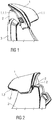
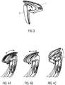
- FIGS 1 to 3 and 4a, 4b and 4c show a headrest 1 according to the invention.
- the headrest 1 has a shape which meets the expected requirements for seating comfort in autonomous vehicles.
- the shape of the lateral wings 1.1 is designed in such a way that lateral support of a person's head is possible.
- the side wings 1.1 of the headrest 1 are shaped in such a way that, although lateral support of the head is made possible, a peripheral view of the person is not impaired, especially when the person is driving the vehicle in which the headrest is arranged.
- the headrest 1 for the seat back 3 of the vehicle seat has two lateral, that is to say laterally projecting, wings 1.1.
- An upper surface 1.1.1 of the wing 1.1 runs from top to bottom with increasing overhang in a driving position, that is to say in an upright position of the headrest 1 and thus in an upright position of the seat back 3.
- the surface 1.1.1 of the wings 1.1 therefore slopes down from the inside to the outside, namely in an upper area, that is to say in the area of a smaller projection, less strongly than in a lower area, that is to say in the area of a larger projection.
- Two reading lights 1.2 and a loudspeaker system with two loudspeakers 1.3 are integrated in the headrest 1.
- the reading lights 1.2, the loudspeakers 1.3 of the loudspeaker system and an optional microphone are always perfectly positioned, in particular regardless of the position of the headrest 1 in relation to the seat back 3 of the vehicle seat and independent of the position of the vehicle seat in the vehicle, for example even with the seat back 3 folded down low or with a vehicle seat rotated 180 ° around the vertical axis.
- the headrest 1 allows an adjustment range to be improved in order to enable support for the head of the person even in a deeply reclined position.
- the result from spatial restrictions The resulting requirements are taken into account by using a slim adjusting mechanism which is at least partially arranged in a connecting element 2.
- each side wing 1.1 a reading lamp 1.2 and a loudspeaker 1.3 are arranged in a common unit.
- FIG. 4c An in Figure 4c
- the adjustment mechanism explained for adjusting the headrest 1 in the Z direction uses a space in the upper region of the seat back 3 to which the headrest 1 is assigned.
- the arrangement of the adjustment mechanism for adjustment in the Z direction in the upper area of the seat back 3 allows greater design freedom, in particular a so-called spine design instead of two simple conventional rods, the appearance of which could be viewed as outdated.
- the headrest can be adjusted in height, i.e. in the Z direction, by 70 mm.
Landscapes
- Engineering & Computer Science (AREA)
- Mechanical Engineering (AREA)
- Transportation (AREA)
- Aviation & Aerospace Engineering (AREA)
- Chair Legs, Seat Parts, And Backrests (AREA)
- Seats For Vehicles (AREA)
- Passenger Equipment (AREA)
Description
- Die Erfindung betrifft eine Kopfstütze für eine Sitzlehne eines Fahrzeugsitzes sowie einen Fahrzeugsitz.
- Im Stand der Technik sind aus
WO 2018/034903 A1 ,WO 2017/160594 A1 undUS 2017/0224117 A Kopfstützen für Fahrzeugsitze bekannt. - Aus
DE 10 2008 061 168 A1 ist eine Kopfstütze mit zwei beweglichen Seitenteilen bekannt. - Aus
DE 102 41 132 A1 ist eine regulierbare Kopfstütze mit verstellbaren, seitlichen Kopfablagen bekannt. - Aus
EP 1 449 713 A2 ist eine Kopfstütze mit verschiebbarem Kopfauflageteil und Komfortflügeln bekannt. - Aus
EP 2 923 886 A1 ist eine Kopfstütze für einen Fahrzeugsitz bekannt, der ein Mittelteil und wenigstens einen Seitenflügel umfasst. - Aus
US 2011 / 227387 A1 ist eine Kopfstütze für ein Fahrzeug bekannt, wobei die Kopfstütze eine erste Oberfläche und eine zweite Oberfläche umfasst. - Die Aufgabe der vorliegenden Erfindung ist es, eine verbesserte Kopfstütze für eine Sitzlehne eines Fahrzeugsitzes sowie einen verbesserten Fahrzeugsitz anzugeben.
- Die Aufgabe wird die Kopfstütze betreffend erfindungsgemäß mit einer Kopfstütze für Fahrzeugsitze mit den in Anspruch 1 angegebenen Merkmalen gelöst.
- Den Fahrzeugsitz betreffend wird die Aufgabe erfindungsgemäß mit den in Anspruch 3 angegebenen Merkmalen gelöst.
- Die Kopfstütze ist besonders für Fahrzeugsitze, insbesondere für Fahrersitze, geeignet, die in einer Komfort-Position oder in einer Fahrposition positionierbar sind, wobei eine Sitzlehne des Fahrzeugsitzes von der Komfort-Position in die Fahrposition bringbar ist und umgekehrt. Eine Komfort-Position ist beispielsweise eine während eines Fahrzustandes eines autonom fahrenden Fahrzeugs eingenommene liegende Position der Sitzlehne, eine Fahrposition des Fahrzeugsitzes ist eine üblicherweise beim Fahrbetrieb eines Menschen eingenommene weitgehend aufrechte Position der Sitzlehne.
- Eine Kopfstütze für eine Sitzlehne eines Fahrzeugsitzes weist zwei seitliche, also seitlich ausladende Flügel auf. Erfindungsgemäß verläuft eine oberseitige Oberfläche der Flügel mit zunehmender Ausladung in einer Fahrposition, also in einer aufrechten Position der Kopfstütze und damit in einer aufrechten Position der Sitzlehne, von oben nach unten.
- Dadurch weist die Kopfstütze eine Form auf, die den zu erwartenden Bedürfnissen einen Sitzkomfort in autonom fahrenden Fahrzeugen betreffend gerecht wird. Die Form der seitlichen Flügel ermöglicht eine seitliche Unterstützung eines Kopfes einer Person. Dabei ermöglicht die Form der seitlichen Flügel der Kopfstütze zwar eine seitliche Unterstützung des Kopfes, dabei ist jedoch eine periphere Sicht der Person, insbesondere wenn diese das Fahrzeug, in welchem die Kopfstütze angeordnet ist, führt, nicht beeinträchtigt.
- Die erfindungsgemäße Kopfstütze sieht eine Anzahl von Leseleuchten vor. Dies ist besonders vorteilhaft, da ein von den Leseleuchten gesendetes Licht besonders gut derart ausrichtbar oder ausgerichtet ist, dass beispielsweise ein Buch, das eine die Kopfstütze nutzende Person liest, besonders zielgenau beleuchtbar oder beleuchtet ist, da die Position des von der Person gehaltenen Buches in aller Regel mit der Position des Kopfes dieser Person korrespondiert und die Position des Kopfes mit der Position der Kopfstütze korrespondiert. Zudem sind üblicherweise in einem Fahrzeughimmel angeordnete Leseleuchten entbehrlich, was baulich einfacher und ästhetisch anspruchsvoller ist. Besonders vorteilhaft ist, dass bei einer Änderung der Position des Kopfes im Fahrzeug, die mit einer Verstellung der Position der Kopfstütze im Fahrzeug korrespondiert, das Leselicht stets an die gewünschte Stelle gesendet wird, ohne dass die Leuchtrichtung gesondert eingestellt werden muss. Dies ist insbesondere auch der Fall, wenn die Sitzlehne verstellt oder sogar wenn der gesamte Fahrzeugsitz um eine vertikale Achse gedreht wird. Durch die genaue Ausrichtung ist ein Leselicht besonders gut ausrichtbar und damit ist die Leseleuchte besonders energiesparend, wodurch eine Emission von Kohlendioxid reduzierbar ist. Zudem werden andere Fahrzeuginsassen dadurch weniger geblendet als bei der Verwendung herkömmlicher Kopfstützen und separater Leseleuchten.
- Erfindungsgemäß sind dabei die Leseleuchten in die seitlichen Flügel integriert. Dadurch sind diese geschützt, optisch kaum erkennbar und damit als ästhetisch empfunden sowie in ihrer Beleuchtungsrichtung besonders sicher mit der Position der Kopfstütze gekoppelt.
- Erfindungsgemäß sind die Leseleuchten unterseitig in die seitlichen Flügel integriert. Dadurch ist auf baulich einfache Weise eine gute Ausrichtung des von den Leseleuchten ausgesendeten Lichts auf ein zu beleuchtendes Objekt möglich.
- Die erfindungsgemäße Kopfstütze sieht eine Anzahl von Lautsprechern vor. Dadurch ist eine gerichtete, sitz- und damit personenindividuelle Beschallung möglich, ohne dass eine gegebenenfalls als unangenehm empfundene Verwendung eines Kopfhörers erforderlich ist und wobei andere Fahrzeuginsassen weniger durch die Beschallung gestört werden, als wenn das gesamte Fahrzeug innen ungerichtet beschallt wird.
- Erfindungsgemäß sind dabei die Lautsprecher in die seitlichen Flügel integriert. Eine Beschallung ist damit besonders zielgerichtet möglich, da sich die Flügel in unmittelbarer Nähe von zu beschallenden Ohren befinden. Dadurch sind die Lautsprecher leistungsarm und damit klein und platzsparend ausbildbar.
- Erfindungsgemäß sind die Lautsprecher unterseitig in die seitlichen Flügel integriert, beispielsweise mit einer gemeinsamen Einheit, die sowohl Lautsprecher als auch Leseleuchten umfasst. Dadurch, dass die Lautsprecher und/oder die Leseleuchten unterseitig in die seitlichen Flügel integriert sind, sind sie optisch kaum erkennbar, wodurch ein ästhetischer Eindruck erzielbar ist.
- Die erfindungsgemäße Kopfstütze sieht eine Anzahl von Mikrofonen vor. Dadurch ist eine gerichtete, sitz- und damit personenindividuelle Spracheingabe, beispielsweise zum Telefonieren oder zur Bedienung einer Vorrichtung oder des Fahrzeugs, möglich, wobei andere Fahrzeuginsassen weniger durch die Spracheingabe gestört werden, als wenn weiter entfernt angeordnete Mikrofone verwendet werden würden.
- Ein Fahrzeugsitz weist eine Sitzlehne auf. Erfindungsgemäß ist eine oben beschriebene Kopfstütze vorgesehen. Der Fahrzeugsitz weist die vorgenannten Vorteile auf, insbesondere kann eine Person, die auf dem Fahrzeugsitz sitzt, ein Objekt stets zielgenau beleuchten und sich zielgenau beschallen lassen, auch wenn der Fahrzeugsitz verstellt wird, beispielsweise eine Neigung der Sitzlehne oder eine Positionierung der Kopfstütze geändert wird oder wenn der gesamte Fahrzeugsitz um eine vertikale Ache gedreht wird, beispielsweise wenn eine Komfort-Position oder eine Fahrposition eingenommen wird.
- Eine Ausgestaltung des erfindungsgemäßen Fahrzeugsitzes sieht ein Verbindungselement zur Verbindung der Kopfstütze mit der Sitzlehne vor. Dabei ist das Verbindungselement zumindest Teil eines Verstellmechanismus zum Verstellen der Kopfstütze. Das Verbindungselement ist gegenüber der Sitzlehne in Z-Richtung verschiebbar und um eine horizontale Achse schwenkbar. Dadurch ist die Kopfstütze einfach und wirkungsvoll verstellbar.
- Bevorzugt ist vorgesehen, dass die Kopfstütze gegenüber dem Verbindungselement zumindest anteilig in einer X-Richtung, also in Fahrzeuglängsrichtung, linear oder zumindest annähernd linear verschiebbar ist. Dadurch ist die Kopfstütze besonders gut in sehr verschiedene, jeweils gewünschte Positionen bringbar.
- Dabei sind besonders bevorzugt die Verschiebung in Z-Richtung, die Verdrehung und die Verschiebung in X-Richtung gleichzeitig vornehmbar, wodurch die Verstellung besonders zügig erfolgen kann.
- Eine weitere Ausgestaltung des erfindungsgemäßen Fahrzeugsitzes sieht eine Verdrehbarkeit des Fahrzeugsitzes gegenüber einem Fahrzeugboden um eine Hochachse vor. Dadurch ist der Fahrzeugsitz einfach von einer Komfort-Position in eine Fahrposition und umgekehrt bringbar.
- Gemäß einer weiteren Ausgestaltung des erfindungsgemäßen Fahrzeugsitzes ist vorgesehen, dass die Verschiebbarkeit in Z-Richtung zwischen 60 mm und 80 mm, insbesondere zwischen 65 mm und 75 mm, beträgt und/oder die Verdrehbarkeit um die horizontale Achse zwischen 5° und 9°, insbesondere zwischen 6° und 8°, beträgt und/oder die Verschiebbarkeit in X-Richtung zwischen 20 mm und 40 mm, insbesondere zwischen 25 mm und 35 mm beträgt. Dadurch ist die Kopfstütze besonders gut in sehr verschiedene, jeweils gewünschte Positionen bringbar und der Fahrzeugsitz damit besonders komfortabel.
- Gemäß einer weiteren Ausgestaltung des erfindungsgemäßen Fahrzeugsitzes ist ein sogenanntes Spine-Design vorgesehen, wobei das Verbindungselement eine einzige, also nicht zergliederte, Verkleidung umfasst, die ein- oder mehrteilig sein kann. Die einzige Verkleidung hat gegenüber einer herkömmlichen Verbindung zwischen Sitzlehne und Fahrzeugsitz mittels zweier Stangen ein sehr ansprechendes optisches Erscheinungsbild.
- Die Ausführungsbeispiele der Erfindungen werden anhand von Zeichnungen näher erläutert. Dabei zeigen:
- Figur 1
- eine Ausführungsform einer erfindungsgemäßen Kopfstütze in perspektivischer Ansicht,
- Figur 2
- eine zugehörige weitere perspektivische Ansicht,
- Figur 3
- eine zugehörige weitere perspektivische Ansicht, und
- Fig. 4a bis 4c
- zugehörige weitere perspektivische Ansichten.
- Einander entsprechende Teile sind in allen Figuren mit den gleichen Bezugszeichen versehen.
-
Figuren 1 bis 3 und4a, 4b und 4c zeigen eine erfindungsgemäße Kopfstütze 1. Die Kopfstütze 1 weist eine Form auf, die den zu erwartenden Bedürfnissen einen Sitzkomfort in autonom fahrenden Fahrzeugen betreffend gerecht wird. Die Form seitlicher Flügel 1.1 ist so ausgebildet, dass eine seitliche Unterstützung eines Kopfes einer Person möglich ist. Dabei sind die seitlichen Flügel 1.1 der Kopfstütze 1 so geformt, dass zwar eine seitliche Unterstützung des Kopfes ermöglicht ist, dass aber eine periphere Sicht der Person, insbesondere wenn diese das Fahrzeug, in welchem die Kopfstütze angeordnet ist, führt, nicht beeinträchtigt ist. - Die Kopfstütze 1 für die Sitzlehne 3 des Fahrzeugsitzes weist zwei seitliche, also seitlich ausladende, Flügel 1.1 auf. Dabei verläuft eine oberseitige Oberfläche 1.1.1 der Flügel 1.1 mit zunehmender Ausladung in einer Fahrposition, also in einer aufrechten Position der Kopfstütze 1 und damit in einer aufrechten Position der Sitzlehne 3, von oben nach unten. Die Oberfläche 1.1.1 der Flügel 1.1 fällt also von innen nach außen ab, und zwar in einem oberen Bereich, also im Bereich geringerer Ausladung, weniger stark als in einem unteren Bereich, also im Bereich größeren Ausladung.
- In der Kopfstütze 1 sind zwei Leseleuchten 1.2 und ein Lautsprechersystem mit zwei Lautsprechern 1.3 integriert. Die Leseleuchten 1.2, die Lautsprecher 1.3 des Lautsprechersystems sowie ein optionales Mikrofon sind dabei stets perfekt positioniert, insbesondere unabhängig von einer Stellung der Kopfstütze 1 zur Sitzlehne 3 des Fahrzeugsitzes und unabhängig von einer Stellung des Fahrzeugsitzes im Fahrzeug, beispielsweise auch bei einer tief abgeklappten Sitzlehne 3 oder bei einem um 180° um die Hochachse gedrehten Fahrzeugsitz. Die Kopfstütze 1 erlaubt eine Verbesserung eines Verstellbereichs, um eine Unterstützung des Kopfes der Person auch in einer tief zurückgelehnten Position zu ermöglichen. Gleichzeitig werden die sich aus räumlichen Beschränkungen ergebenden Erfordernisse berücksichtigt, indem ein schlanker Verstellmechanismus verwendet wird, der zumindest anteilig in einem Verbindungselement 2 angeordnet ist.
- In jedem seitlichen Flügel 1.1 sind jeweils eine Leseleuchte 1.2 und ein Lautsprecher 1.3 in einer gemeinsamen Einheit angeordnet.
- Eine in den
Figuren 4a und 4b gezeigte Verstellung der Kopfstütze 1 in X-Richtung ist ermöglicht durch eine insbesondere elektrisch angetriebene Verstellung der Kopfstütze 1, wobei eine Verstellung in X-Richtung um 30 mm durch Verdrehung der Kopfstütze um 7° kombinierbar ist mit einer zusätzlichen Verschiebung um 30 mm in X-Richtung als lineare Verschiebung. - Ein in
Figur 4c erläuterter Verstellmechanismus für eine Verstellung der Kopfstütze 1 in Z-Richtung nutzt einen Raum im oberen Bereich der Sitzlehne 3, welcher die Kopfstütze 1 zugeordnet ist. Die Anordnung des Verstellmechanismus für die Verstellung in Z-Richtung im oberen Bereich der Sitzlehne 3 erlaubt eine größere gestalterische Freiheit, insbesondere ein so genanntes Spine-Design anstelle zweier einfacher herkömmlicher Stangen, deren Erscheinungsbild als überholt angesehen werden könnte. Die Kopfstütze ist in der Höhe, also in Z-Richtung, um 70 mm verstellbar. -
- 1
- Kopfstütze
- 1.1
- seitliche Flügel
- 1.1.1
- oberseitige Oberfläche
- 1.2
- Leseleuchte
- 1.3
- Lautsprecher
- 2
- Verbindungselement
- 3
- Sitzlehne
Claims (7)
- Kopfstütze (1) für eine Sitzlehne (3) eines Fahrzeugsitzes, aufweisend zwei seitliche Flügel (1.1),wobei eine oberseitige Oberfläche (1.1.1) der Flügel (1.1) mit zunehmender Ausladung in einer Fahrposition von oben nach unten verläuft,wobei Leseleuchten (1.2) in die seitlichen Flügel (1.1) integriert sind undwobei Lautsprecher (1.3) und/oder Mikrofone in die seitlichen Flügel (1.1) integriert sindwobei die Leseleuchten (1.2) unterseitig in die seitlichen Flügel (1.1) integriert sind, wobei die Lautsprecher (1.3)und/oder die Mikrofone unterseitig in die seitlichen Flügel (1.1) integriert sind und wobei die Kopfstütze (1) einschließlich der zwei seitlichen Flügel (1.1) eine durchgängige Kopfanlagefläche aufweist.
- Fahrzeugsitz, aufweisend eine Sitzlehne (3), gekennzeichnet durch eine Kopfstütze (1) nach einem der vorhergehenden Ansprüche.
- Fahrzeugsitz nach Anspruch 2, gekennzeichnet durch ein Verbindungselement (2) zur Verbindung der Kopfstütze (1) mit der Sitzlehne (3), wobei das Verbindungselement (2) zumindest Teil eines Verstellmechanismus ist und wobei das Verbindungselement (2) gegenüber der Sitzlehne (3) in Z-Richtung verschiebbar und um eine horizontale Achse schwenkbar ist.
- Fahrzeugsitz nach Anspruch 2 oder 3, dadurch gekennzeichnet, dass die Kopfstütze (1) gegenüber dem Verbindungselement (2) zumindest anteilig in einer X-Richtung linear verschiebbar ist.
- Fahrzeugsitz nach Anspruch 4, dadurch gekennzeichnet, dass die Verschiebung in Z-Richtung, die Verdrehung und die Verschiebung in X-Richtung gleichzeitig vornehmbar sind.
- Fahrzeugsitz nach einem der Ansprüche 2-5, gekennzeichnet durch eine Verdrehbarkeit um eine Hochachse.
- Fahrzeugsitz nach einem der Ansprüche 3-6, dadurch gekennzeichnet, dass- die Verschiebbarkeit in Z-Richtung zwischen 60 mm und 80 mm beträgt und/oder- die Verdrehbarkeit um die horizontale Achse zwischen 5° und 9° beträgt und/oder- die Verschiebbarkeit in X-Richtung zwischen 20 mm und 40 mm beträgt.
Applications Claiming Priority (2)
| Application Number | Priority Date | Filing Date | Title |
|---|---|---|---|
| DE102017216116 | 2017-09-12 | ||
| PCT/EP2018/074370 WO2019052976A1 (de) | 2017-09-12 | 2018-09-11 | Kopfstütze für eine sitzlehne eines fahrzeugsitzes und fahrzeugsitz |
Publications (2)
| Publication Number | Publication Date |
|---|---|
| EP3681759A1 EP3681759A1 (de) | 2020-07-22 |
| EP3681759B1 true EP3681759B1 (de) | 2021-09-01 |
Family
ID=63556343
Family Applications (1)
| Application Number | Title | Priority Date | Filing Date |
|---|---|---|---|
| EP18768870.0A Active EP3681759B1 (de) | 2017-09-12 | 2018-09-11 | Kopfstütze für eine sitzlehne eines fahrzeugsitzes und fahrzeugsitz |
Country Status (5)
| Country | Link |
|---|---|
| US (1) | US20200282888A1 (de) |
| EP (1) | EP3681759B1 (de) |
| CN (1) | CN111094062B (de) |
| DE (2) | DE102018215377B4 (de) |
| WO (1) | WO2019052976A1 (de) |
Family Cites Families (27)
| Publication number | Priority date | Publication date | Assignee | Title |
|---|---|---|---|---|
| US3537750A (en) * | 1968-07-03 | 1970-11-03 | Gen Motors Corp | Headrest assembly |
| DE1920320A1 (de) * | 1969-04-22 | 1970-11-12 | Adolf Benz | Sicherheitskopfstuetze fuer Fahrzeuge |
| SE420394B (sv) * | 1979-06-08 | 1981-10-05 | Saab Scania Ab | Nackskydd for en stol, foretredesvis en fordonsstol |
| US7264313B2 (en) * | 2000-09-20 | 2007-09-04 | Robert Clough | Seat headrest |
| US6805322B2 (en) | 2002-08-15 | 2004-10-19 | The Boeing Company | Multiple-position seat |
| DE10241132B4 (de) * | 2002-09-03 | 2008-01-03 | Peguform Gmbh | Mehrteiliger Verstellmechanismus für eine Kopfstütze |
| DE10361958A1 (de) * | 2003-02-24 | 2004-10-14 | Volkswagen Ag | Kopfstütze mit verschiebbarem Kopfstützenauflageteil und Kopfstützen-Komfortflügeln |
| GB0402720D0 (en) | 2004-02-07 | 2004-03-10 | Bentley Motors Ltd | A rest |
| US7316451B2 (en) * | 2004-06-01 | 2008-01-08 | Cosco Management, Inc. | Wearable side impact protector |
| DE502005004107D1 (de) | 2005-02-22 | 2008-06-26 | Ford Global Tech Llc | Sitzreihen-Anordnung eines Fahrzeuges |
| US7625043B2 (en) * | 2005-09-15 | 2009-12-01 | Wonderland Nurserygoods Co., Ltd. | Child car seat with multiple use configurations |
| JP4422755B2 (ja) | 2007-12-21 | 2010-02-24 | トヨタ自動車株式会社 | 乗物用シート配置構造 |
| DE102008061168A1 (de) * | 2008-12-09 | 2009-09-03 | Daimler Ag | Kopfstütze eines Fahrzeugsitzes und Kraftfahrzeug mit einer Kopfstütze |
| US20110227387A1 (en) * | 2010-03-16 | 2011-09-22 | Michael Kolich | Occupant controlled multi-surface head restraint for improved comfort |
| FR2986754B1 (fr) | 2012-02-13 | 2014-03-14 | Renault Sa | Ensemble pour la reception d'un talon d'un utilisateur d'un vehicule automobile |
| CN102632820A (zh) * | 2012-03-28 | 2012-08-15 | 长春富维—江森自控汽车饰件系统有限公司 | 汽车座椅头枕 |
| US9061616B2 (en) * | 2013-01-24 | 2015-06-23 | Ford Global Technologies, Llc | Articulating headrest assembly |
| DE102013018387B4 (de) | 2013-10-26 | 2018-01-04 | Audi Ag | Rücksitz für Fahrzeuge |
| DE102015201540B4 (de) | 2014-03-07 | 2018-05-30 | Volkswagen Aktiengesellschaft | Verfahren und Vorrichtung zum Betreiben eines Fahrzeugs mit einem automatischen Fahrmodus |
| DE102015103279B4 (de) * | 2014-03-20 | 2024-02-29 | Ford Global Technologies, Llc | Autonomes Fahrzeug mit rekonfigurierbarem Innenraum |
| DE102014205456A1 (de) * | 2014-03-24 | 2015-09-24 | Ford Global Technologies, Llc | Kopfstütze für einen Fahrzeugsitz |
| DE102014207288A1 (de) | 2014-04-16 | 2015-10-22 | Johnson Controls Technology Company | Sitzanlage für ein kraftfahrzeug |
| US9821697B2 (en) | 2016-02-02 | 2017-11-21 | Ford Global Technologies, Llc | Inflatable cushion disposed between front and rear seats of a vehicle |
| US10327554B2 (en) | 2016-02-10 | 2019-06-25 | The Comfort Companies, Llc | Adjustable head support |
| US10239432B2 (en) | 2016-03-17 | 2019-03-26 | Bose Corporation | Acoustic output through headrest wings |
| CN205674909U (zh) * | 2016-06-22 | 2016-11-09 | 郑永贵 | 一种新型多功能汽车座椅 |
| US10933787B2 (en) | 2016-08-19 | 2021-03-02 | Adient Luxembourg Holding S.Á R.L. | Head restraint follower |
-
2018
- 2018-09-11 CN CN201880059159.7A patent/CN111094062B/zh active Active
- 2018-09-11 DE DE102018215377.9A patent/DE102018215377B4/de not_active Expired - Fee Related
- 2018-09-11 DE DE102018215374.4A patent/DE102018215374B4/de active Active
- 2018-09-11 US US16/646,680 patent/US20200282888A1/en not_active Abandoned
- 2018-09-11 EP EP18768870.0A patent/EP3681759B1/de active Active
- 2018-09-11 WO PCT/EP2018/074370 patent/WO2019052976A1/de not_active Ceased
Also Published As
| Publication number | Publication date |
|---|---|
| WO2019052976A1 (de) | 2019-03-21 |
| DE102018215377A1 (de) | 2019-03-14 |
| DE102018215377B4 (de) | 2022-11-17 |
| CN111094062B (zh) | 2023-08-22 |
| DE102018215374A1 (de) | 2019-03-14 |
| US20200282888A1 (en) | 2020-09-10 |
| EP3681759A1 (de) | 2020-07-22 |
| CN111094062A (zh) | 2020-05-01 |
| DE102018215374B4 (de) | 2019-10-17 |
Similar Documents
| Publication | Publication Date | Title |
|---|---|---|
| DE102007007116B4 (de) | Fahrzeugsitzanordnung mit beweglichen Polstern | |
| DE102010002861B4 (de) | Fahrzeug mit mindestens einem Individualsitzplatz für einen mitfahrenden Fahrzeuginsassen | |
| DE112006002394T5 (de) | Vorrichtung und Verfahren für eine konfigurierbare Sitzgelegenheit | |
| DE102016100316A1 (de) | Für verbesserten zugang ausgelegter fahrzeugsitz | |
| EP0763466A1 (de) | Versorgungseinheit für Passagiere, insbesondere in einer Passagierkabine eines Flugzeuges | |
| WO2021043705A1 (de) | Morphende sitzbank | |
| EP3553374A1 (de) | Halbleiterbasierte beleuchtungsvorrichtung | |
| WO2001030203A1 (de) | Sitz | |
| DE112017003638B4 (de) | Vorrichtung und Verfahren zur Steuerung einer Kopfstütze eines Fahrzeugsitzes | |
| DE102018101706A1 (de) | Fahrzeugsitz | |
| WO2000027665A1 (de) | Vorrichtung und verfahren zur einstellung eines fahrzeugsitzes | |
| DE19952894A1 (de) | Versenkbare Monitor- oder Displayanordnung für Kraftfahrzeuge | |
| DE102020211258A1 (de) | Innenraumverstellsystem für ein Fahrzeug | |
| EP1582457B1 (de) | Fahrzeugsitz, insbesondere Fluggastsitz | |
| DE19926519B4 (de) | Bedienelement zur elektrischen Sitzverstellung von Kfz-Sitzen | |
| EP1449713A2 (de) | Kopfstütze mit verschiebbarem Kopfauflageteil und Komfortflügeln | |
| EP4474194B1 (de) | Haltevorrichtung in einem fahrzeug für ein eingabegerät mit einer anzeige | |
| EP3681759A1 (de) | Kopfstütze für eine sitzlehne eines fahrzeugsitzes und fahrzeugsitz | |
| DE102007028034B4 (de) | Fahrzeugsitz mit einem schwenkbaren Schulter- und Kopfbereich | |
| DE102019208755B4 (de) | Kopfstütze für einen Sitz und Sitz | |
| DE102016215498B4 (de) | Trenneinrichtung zur Abschirmung eines Sitzplatzes eines Fahrzeugsitzes | |
| WO2020152139A1 (de) | Mehrfunktionstafel-vorrichtung zur anordnung in einem kraftfahrzeug | |
| DE102005015238B4 (de) | Funktionssystem | |
| DE10241250B4 (de) | Sitzeinrichtung | |
| DE102023109445B3 (de) | Vorrichtung zum Betreiben einer Display-Anordnung für ein Fahrzeugdach und Fahrzeugdach für ein Kraftfahrzeug |
Legal Events
| Date | Code | Title | Description |
|---|---|---|---|
| STAA | Information on the status of an ep patent application or granted ep patent |
Free format text: STATUS: UNKNOWN |
|
| STAA | Information on the status of an ep patent application or granted ep patent |
Free format text: STATUS: THE INTERNATIONAL PUBLICATION HAS BEEN MADE |
|
| PUAI | Public reference made under article 153(3) epc to a published international application that has entered the european phase |
Free format text: ORIGINAL CODE: 0009012 |
|
| STAA | Information on the status of an ep patent application or granted ep patent |
Free format text: STATUS: REQUEST FOR EXAMINATION WAS MADE |
|
| 17P | Request for examination filed |
Effective date: 20200414 |
|
| AK | Designated contracting states |
Kind code of ref document: A1 Designated state(s): AL AT BE BG CH CY CZ DE DK EE ES FI FR GB GR HR HU IE IS IT LI LT LU LV MC MK MT NL NO PL PT RO RS SE SI SK SM TR |
|
| AX | Request for extension of the european patent |
Extension state: BA ME |
|
| DAV | Request for validation of the european patent (deleted) | ||
| DAX | Request for extension of the european patent (deleted) | ||
| REG | Reference to a national code |
Ref country code: DE Ref legal event code: R079 Ref document number: 502018006883 Country of ref document: DE Free format text: PREVIOUS MAIN CLASS: B60N0002885000 Ipc: B60N0002040000 |
|
| GRAP | Despatch of communication of intention to grant a patent |
Free format text: ORIGINAL CODE: EPIDOSNIGR1 |
|
| STAA | Information on the status of an ep patent application or granted ep patent |
Free format text: STATUS: GRANT OF PATENT IS INTENDED |
|
| INTG | Intention to grant announced |
Effective date: 20210325 |
|
| RIC1 | Information provided on ipc code assigned before grant |
Ipc: B60N 2/02 20060101ALI20210312BHEP Ipc: B60N 2/865 20180101ALI20210312BHEP Ipc: B60N 2/879 20180101ALI20210312BHEP Ipc: B60Q 3/233 20170101ALI20210312BHEP Ipc: B60N 2/885 20180101ALI20210312BHEP Ipc: B60N 3/06 20060101ALI20210312BHEP Ipc: B60N 2/14 20060101ALI20210312BHEP Ipc: B60N 2/06 20060101ALI20210312BHEP Ipc: B60N 2/04 20060101AFI20210312BHEP |
|
| GRAS | Grant fee paid |
Free format text: ORIGINAL CODE: EPIDOSNIGR3 |
|
| GRAA | (expected) grant |
Free format text: ORIGINAL CODE: 0009210 |
|
| STAA | Information on the status of an ep patent application or granted ep patent |
Free format text: STATUS: THE PATENT HAS BEEN GRANTED |
|
| AK | Designated contracting states |
Kind code of ref document: B1 Designated state(s): AL AT BE BG CH CY CZ DE DK EE ES FI FR GB GR HR HU IE IS IT LI LT LU LV MC MK MT NL NO PL PT RO RS SE SI SK SM TR |
|
| REG | Reference to a national code |
Ref country code: GB Ref legal event code: FG4D Free format text: NOT ENGLISH |
|
| REG | Reference to a national code |
Ref country code: CH Ref legal event code: EP Ref country code: AT Ref legal event code: REF Ref document number: 1425888 Country of ref document: AT Kind code of ref document: T Effective date: 20210915 |
|
| REG | Reference to a national code |
Ref country code: DE Ref legal event code: R096 Ref document number: 502018006883 Country of ref document: DE |
|
| REG | Reference to a national code |
Ref country code: IE Ref legal event code: FG4D Free format text: LANGUAGE OF EP DOCUMENT: GERMAN |
|
| REG | Reference to a national code |
Ref country code: SE Ref legal event code: TRGR |
|
| REG | Reference to a national code |
Ref country code: LT Ref legal event code: MG9D |
|
| REG | Reference to a national code |
Ref country code: NL Ref legal event code: MP Effective date: 20210901 |
|
| REG | Reference to a national code |
Ref country code: DE Ref legal event code: R082 Ref document number: 502018006883 Country of ref document: DE Representative=s name: LIEDHEGENER, RALF, DIPL.-ING., DE Ref country code: DE Ref legal event code: R082 Ref document number: 502018006883 Country of ref document: DE Representative=s name: LIEDTKE & PARTNER PATENTANWAELTE, DE |
|
| PG25 | Lapsed in a contracting state [announced via postgrant information from national office to epo] |
Ref country code: RS Free format text: LAPSE BECAUSE OF FAILURE TO SUBMIT A TRANSLATION OF THE DESCRIPTION OR TO PAY THE FEE WITHIN THE PRESCRIBED TIME-LIMIT Effective date: 20210901 Ref country code: FI Free format text: LAPSE BECAUSE OF FAILURE TO SUBMIT A TRANSLATION OF THE DESCRIPTION OR TO PAY THE FEE WITHIN THE PRESCRIBED TIME-LIMIT Effective date: 20210901 Ref country code: ES Free format text: LAPSE BECAUSE OF FAILURE TO SUBMIT A TRANSLATION OF THE DESCRIPTION OR TO PAY THE FEE WITHIN THE PRESCRIBED TIME-LIMIT Effective date: 20210901 Ref country code: HR Free format text: LAPSE BECAUSE OF FAILURE TO SUBMIT A TRANSLATION OF THE DESCRIPTION OR TO PAY THE FEE WITHIN THE PRESCRIBED TIME-LIMIT Effective date: 20210901 Ref country code: LT Free format text: LAPSE BECAUSE OF FAILURE TO SUBMIT A TRANSLATION OF THE DESCRIPTION OR TO PAY THE FEE WITHIN THE PRESCRIBED TIME-LIMIT Effective date: 20210901 Ref country code: BG Free format text: LAPSE BECAUSE OF FAILURE TO SUBMIT A TRANSLATION OF THE DESCRIPTION OR TO PAY THE FEE WITHIN THE PRESCRIBED TIME-LIMIT Effective date: 20211201 Ref country code: NO Free format text: LAPSE BECAUSE OF FAILURE TO SUBMIT A TRANSLATION OF THE DESCRIPTION OR TO PAY THE FEE WITHIN THE PRESCRIBED TIME-LIMIT Effective date: 20211201 |
|
| PG25 | Lapsed in a contracting state [announced via postgrant information from national office to epo] |
Ref country code: PL Free format text: LAPSE BECAUSE OF FAILURE TO SUBMIT A TRANSLATION OF THE DESCRIPTION OR TO PAY THE FEE WITHIN THE PRESCRIBED TIME-LIMIT Effective date: 20210901 Ref country code: LV Free format text: LAPSE BECAUSE OF FAILURE TO SUBMIT A TRANSLATION OF THE DESCRIPTION OR TO PAY THE FEE WITHIN THE PRESCRIBED TIME-LIMIT Effective date: 20210901 Ref country code: GR Free format text: LAPSE BECAUSE OF FAILURE TO SUBMIT A TRANSLATION OF THE DESCRIPTION OR TO PAY THE FEE WITHIN THE PRESCRIBED TIME-LIMIT Effective date: 20211202 |
|
| REG | Reference to a national code |
Ref country code: CH Ref legal event code: PL |
|
| REG | Reference to a national code |
Ref country code: BE Ref legal event code: MM Effective date: 20210930 |
|
| PG25 | Lapsed in a contracting state [announced via postgrant information from national office to epo] |
Ref country code: IS Free format text: LAPSE BECAUSE OF FAILURE TO SUBMIT A TRANSLATION OF THE DESCRIPTION OR TO PAY THE FEE WITHIN THE PRESCRIBED TIME-LIMIT Effective date: 20220101 Ref country code: SM Free format text: LAPSE BECAUSE OF FAILURE TO SUBMIT A TRANSLATION OF THE DESCRIPTION OR TO PAY THE FEE WITHIN THE PRESCRIBED TIME-LIMIT Effective date: 20210901 Ref country code: SK Free format text: LAPSE BECAUSE OF FAILURE TO SUBMIT A TRANSLATION OF THE DESCRIPTION OR TO PAY THE FEE WITHIN THE PRESCRIBED TIME-LIMIT Effective date: 20210901 Ref country code: RO Free format text: LAPSE BECAUSE OF FAILURE TO SUBMIT A TRANSLATION OF THE DESCRIPTION OR TO PAY THE FEE WITHIN THE PRESCRIBED TIME-LIMIT Effective date: 20210901 Ref country code: PT Free format text: LAPSE BECAUSE OF FAILURE TO SUBMIT A TRANSLATION OF THE DESCRIPTION OR TO PAY THE FEE WITHIN THE PRESCRIBED TIME-LIMIT Effective date: 20220103 Ref country code: NL Free format text: LAPSE BECAUSE OF FAILURE TO SUBMIT A TRANSLATION OF THE DESCRIPTION OR TO PAY THE FEE WITHIN THE PRESCRIBED TIME-LIMIT Effective date: 20210901 Ref country code: EE Free format text: LAPSE BECAUSE OF FAILURE TO SUBMIT A TRANSLATION OF THE DESCRIPTION OR TO PAY THE FEE WITHIN THE PRESCRIBED TIME-LIMIT Effective date: 20210901 Ref country code: CZ Free format text: LAPSE BECAUSE OF FAILURE TO SUBMIT A TRANSLATION OF THE DESCRIPTION OR TO PAY THE FEE WITHIN THE PRESCRIBED TIME-LIMIT Effective date: 20210901 Ref country code: AL Free format text: LAPSE BECAUSE OF FAILURE TO SUBMIT A TRANSLATION OF THE DESCRIPTION OR TO PAY THE FEE WITHIN THE PRESCRIBED TIME-LIMIT Effective date: 20210901 |
|
| REG | Reference to a national code |
Ref country code: DE Ref legal event code: R097 Ref document number: 502018006883 Country of ref document: DE |
|
| RAP2 | Party data changed (patent owner data changed or rights of a patent transferred) |
Owner name: ADIENT US LLC |
|
| PG25 | Lapsed in a contracting state [announced via postgrant information from national office to epo] |
Ref country code: MC Free format text: LAPSE BECAUSE OF FAILURE TO SUBMIT A TRANSLATION OF THE DESCRIPTION OR TO PAY THE FEE WITHIN THE PRESCRIBED TIME-LIMIT Effective date: 20210901 |
|
| PLBE | No opposition filed within time limit |
Free format text: ORIGINAL CODE: 0009261 |
|
| STAA | Information on the status of an ep patent application or granted ep patent |
Free format text: STATUS: NO OPPOSITION FILED WITHIN TIME LIMIT |
|
| REG | Reference to a national code |
Ref country code: DE Ref legal event code: R081 Ref document number: 502018006883 Country of ref document: DE Owner name: ADIENT US LLC, PLYMOUTH, US Free format text: FORMER OWNER: ADIENT ENGINEERING AND IP GMBH, 51399 BURSCHEID, DE |
|
| PG25 | Lapsed in a contracting state [announced via postgrant information from national office to epo] |
Ref country code: LU Free format text: LAPSE BECAUSE OF NON-PAYMENT OF DUE FEES Effective date: 20210911 Ref country code: IT Free format text: LAPSE BECAUSE OF FAILURE TO SUBMIT A TRANSLATION OF THE DESCRIPTION OR TO PAY THE FEE WITHIN THE PRESCRIBED TIME-LIMIT Effective date: 20210901 Ref country code: IE Free format text: LAPSE BECAUSE OF NON-PAYMENT OF DUE FEES Effective date: 20210911 Ref country code: DK Free format text: LAPSE BECAUSE OF FAILURE TO SUBMIT A TRANSLATION OF THE DESCRIPTION OR TO PAY THE FEE WITHIN THE PRESCRIBED TIME-LIMIT Effective date: 20210901 Ref country code: BE Free format text: LAPSE BECAUSE OF NON-PAYMENT OF DUE FEES Effective date: 20210930 |
|
| 26N | No opposition filed |
Effective date: 20220602 |
|
| PG25 | Lapsed in a contracting state [announced via postgrant information from national office to epo] |
Ref country code: SI Free format text: LAPSE BECAUSE OF FAILURE TO SUBMIT A TRANSLATION OF THE DESCRIPTION OR TO PAY THE FEE WITHIN THE PRESCRIBED TIME-LIMIT Effective date: 20210901 Ref country code: LI Free format text: LAPSE BECAUSE OF NON-PAYMENT OF DUE FEES Effective date: 20210930 Ref country code: CH Free format text: LAPSE BECAUSE OF NON-PAYMENT OF DUE FEES Effective date: 20210930 |
|
| GBPC | Gb: european patent ceased through non-payment of renewal fee |
Effective date: 20220911 |
|
| PG25 | Lapsed in a contracting state [announced via postgrant information from national office to epo] |
Ref country code: CY Free format text: LAPSE BECAUSE OF FAILURE TO SUBMIT A TRANSLATION OF THE DESCRIPTION OR TO PAY THE FEE WITHIN THE PRESCRIBED TIME-LIMIT Effective date: 20210901 |
|
| PG25 | Lapsed in a contracting state [announced via postgrant information from national office to epo] |
Ref country code: HU Free format text: LAPSE BECAUSE OF FAILURE TO SUBMIT A TRANSLATION OF THE DESCRIPTION OR TO PAY THE FEE WITHIN THE PRESCRIBED TIME-LIMIT; INVALID AB INITIO Effective date: 20180911 |
|
| PG25 | Lapsed in a contracting state [announced via postgrant information from national office to epo] |
Ref country code: GB Free format text: LAPSE BECAUSE OF NON-PAYMENT OF DUE FEES Effective date: 20220911 |
|
| PG25 | Lapsed in a contracting state [announced via postgrant information from national office to epo] |
Ref country code: MK Free format text: LAPSE BECAUSE OF FAILURE TO SUBMIT A TRANSLATION OF THE DESCRIPTION OR TO PAY THE FEE WITHIN THE PRESCRIBED TIME-LIMIT Effective date: 20210901 |
|
| PG25 | Lapsed in a contracting state [announced via postgrant information from national office to epo] |
Ref country code: TR Free format text: LAPSE BECAUSE OF FAILURE TO SUBMIT A TRANSLATION OF THE DESCRIPTION OR TO PAY THE FEE WITHIN THE PRESCRIBED TIME-LIMIT Effective date: 20210901 |
|
| PG25 | Lapsed in a contracting state [announced via postgrant information from national office to epo] |
Ref country code: MT Free format text: LAPSE BECAUSE OF FAILURE TO SUBMIT A TRANSLATION OF THE DESCRIPTION OR TO PAY THE FEE WITHIN THE PRESCRIBED TIME-LIMIT Effective date: 20210901 |
|
| REG | Reference to a national code |
Ref country code: AT Ref legal event code: MM01 Ref document number: 1425888 Country of ref document: AT Kind code of ref document: T Effective date: 20230911 |
|
| PG25 | Lapsed in a contracting state [announced via postgrant information from national office to epo] |
Ref country code: AT Free format text: LAPSE BECAUSE OF NON-PAYMENT OF DUE FEES Effective date: 20230911 |
|
| PG25 | Lapsed in a contracting state [announced via postgrant information from national office to epo] |
Ref country code: AT Free format text: LAPSE BECAUSE OF NON-PAYMENT OF DUE FEES Effective date: 20230911 |
|
| REG | Reference to a national code |
Ref country code: DE Ref legal event code: R082 Ref document number: 502018006883 Country of ref document: DE Representative=s name: LIEDTKE & PARTNER PATENTANWAELTE, DE |
|
| PGFP | Annual fee paid to national office [announced via postgrant information from national office to epo] |
Ref country code: DE Payment date: 20250929 Year of fee payment: 8 |
|
| PGFP | Annual fee paid to national office [announced via postgrant information from national office to epo] |
Ref country code: FR Payment date: 20250925 Year of fee payment: 8 |
|
| PGFP | Annual fee paid to national office [announced via postgrant information from national office to epo] |
Ref country code: SE Payment date: 20250927 Year of fee payment: 8 |
|
| PGFP | Annual fee paid to national office [announced via postgrant information from national office to epo] |
Ref country code: AT Payment date: 20260410 Year of fee payment: 5 |