EP3680892A1 - Verstellbare tragevorrichtung für ein musikinstrument - Google Patents
Verstellbare tragevorrichtung für ein musikinstrument Download PDFInfo
- Publication number
- EP3680892A1 EP3680892A1 EP20150378.6A EP20150378A EP3680892A1 EP 3680892 A1 EP3680892 A1 EP 3680892A1 EP 20150378 A EP20150378 A EP 20150378A EP 3680892 A1 EP3680892 A1 EP 3680892A1
- Authority
- EP
- European Patent Office
- Prior art keywords
- cord
- insert
- cup
- recess
- groove
- Prior art date
- Legal status (The legal status is an assumption and is not a legal conclusion. Google has not performed a legal analysis and makes no representation as to the accuracy of the status listed.)
- Granted
Links
- 230000002401 inhibitory effect Effects 0.000 claims abstract description 20
- 230000002093 peripheral effect Effects 0.000 claims description 30
- 210000003811 finger Anatomy 0.000 description 3
- 238000000926 separation method Methods 0.000 description 3
- 210000003813 thumb Anatomy 0.000 description 3
- 230000003247 decreasing effect Effects 0.000 description 2
- 239000002131 composite material Substances 0.000 description 1
- 230000000694 effects Effects 0.000 description 1
- 210000004247 hand Anatomy 0.000 description 1
- 239000000203 mixture Substances 0.000 description 1
Images


Classifications
-
- G—PHYSICS
- G10—MUSICAL INSTRUMENTS; ACOUSTICS
- G10G—REPRESENTATION OF MUSIC; RECORDING MUSIC IN NOTATION FORM; ACCESSORIES FOR MUSIC OR MUSICAL INSTRUMENTS NOT OTHERWISE PROVIDED FOR, e.g. SUPPORTS
- G10G5/00—Supports for musical instruments
- G10G5/005—Supports for musical instruments while playing, e.g. cord, strap or harness
-
- A—HUMAN NECESSITIES
- A45—HAND OR TRAVELLING ARTICLES
- A45F—TRAVELLING OR CAMP EQUIPMENT: SACKS OR PACKS CARRIED ON THE BODY
- A45F5/00—Holders or carriers for hand articles; Holders or carriers for use while travelling or camping
-
- F—MECHANICAL ENGINEERING; LIGHTING; HEATING; WEAPONS; BLASTING
- F16—ENGINEERING ELEMENTS AND UNITS; GENERAL MEASURES FOR PRODUCING AND MAINTAINING EFFECTIVE FUNCTIONING OF MACHINES OR INSTALLATIONS; THERMAL INSULATION IN GENERAL
- F16G—BELTS, CABLES, OR ROPES, PREDOMINANTLY USED FOR DRIVING PURPOSES; CHAINS; FITTINGS PREDOMINANTLY USED THEREFOR
- F16G11/00—Means for fastening cables or ropes to one another or to other objects; Caps or sleeves for fixing on cables or ropes
- F16G11/10—Quick-acting fastenings; Clamps holding in one direction only
- F16G11/101—Quick-acting fastenings; Clamps holding in one direction only deforming the cable by moving a part of the fastener
-
- F—MECHANICAL ENGINEERING; LIGHTING; HEATING; WEAPONS; BLASTING
- F16—ENGINEERING ELEMENTS AND UNITS; GENERAL MEASURES FOR PRODUCING AND MAINTAINING EFFECTIVE FUNCTIONING OF MACHINES OR INSTALLATIONS; THERMAL INSULATION IN GENERAL
- F16G—BELTS, CABLES, OR ROPES, PREDOMINANTLY USED FOR DRIVING PURPOSES; CHAINS; FITTINGS PREDOMINANTLY USED THEREFOR
- F16G11/00—Means for fastening cables or ropes to one another or to other objects; Caps or sleeves for fixing on cables or ropes
- F16G11/14—Devices or coupling-pieces designed for easy formation of adjustable loops, e.g. choker hooks; Hooks or eyes with integral parts designed to facilitate quick attachment to cables or ropes at any point, e.g. by forming loops
-
- G—PHYSICS
- G10—MUSICAL INSTRUMENTS; ACOUSTICS
- G10D—STRINGED MUSICAL INSTRUMENTS; WIND MUSICAL INSTRUMENTS; ACCORDIONS OR CONCERTINAS; PERCUSSION MUSICAL INSTRUMENTS; AEOLIAN HARPS; SINGING-FLAME MUSICAL INSTRUMENTS; MUSICAL INSTRUMENTS NOT OTHERWISE PROVIDED FOR
- G10D9/00—Details of, or accessories for, wind musical instruments
-
- A—HUMAN NECESSITIES
- A45—HAND OR TRAVELLING ARTICLES
- A45F—TRAVELLING OR CAMP EQUIPMENT: SACKS OR PACKS CARRIED ON THE BODY
- A45F3/00—Travelling or camp articles; Sacks or packs carried on the body
- A45F3/14—Carrying-straps; Pack-carrying harnesses
- A45F2003/142—Carrying-straps
-
- A—HUMAN NECESSITIES
- A45—HAND OR TRAVELLING ARTICLES
- A45F—TRAVELLING OR CAMP EQUIPMENT: SACKS OR PACKS CARRIED ON THE BODY
- A45F5/00—Holders or carriers for hand articles; Holders or carriers for use while travelling or camping
- A45F2005/006—Holders or carriers for hand articles; Holders or carriers for use while travelling or camping comprising a suspension strap or lanyard
-
- Y—GENERAL TAGGING OF NEW TECHNOLOGICAL DEVELOPMENTS; GENERAL TAGGING OF CROSS-SECTIONAL TECHNOLOGIES SPANNING OVER SEVERAL SECTIONS OF THE IPC; TECHNICAL SUBJECTS COVERED BY FORMER USPC CROSS-REFERENCE ART COLLECTIONS [XRACs] AND DIGESTS
- Y10—TECHNICAL SUBJECTS COVERED BY FORMER USPC
- Y10S—TECHNICAL SUBJECTS COVERED BY FORMER USPC CROSS-REFERENCE ART COLLECTIONS [XRACs] AND DIGESTS
- Y10S224/00—Package and article carriers
- Y10S224/91—Carrier for musical instrument
Definitions
- the invention relates to a device for adjusting the length of a cord for carrying a musical instrument, in particular a saxophone, a bass clarinet, a bassoon or a similar wind instrument.
- a wind instrument such as a saxophone is often carried by a carrying device on the neck or shoulders due to its weight.
- a carrying device comprises a carrying strap, also called a carrying strap, which is placed around the neck or a carrying frame, which is placed on the shoulders, and a cord, which is attached on the one hand to the carrying strap or frame and on the other hand with a hook on the instrument.
- a support frame as mentioned is for example in CH 704201 disclosed.
- a strap or carrying frame with a cord enables a heavy instrument to be played over a longer period of time without the musician becoming too tired.
- a cord for such a carrying device is, for example, twisted twice on the hook, as for example in US 1,637,003 discloses, wherein the double loop leads over a slider.
- the slider can be moved up and down, which varies the length of the double loop and the height position of the instrument.
- the slide comprises a cuboid element which is placed together with a spring in a cup-shaped element.
- the cuboid and the cup-shaped element each contain an opening through which three sections of the cord can be passed, the three sections touching each other in the opening. At When the spring is relaxed, the openings only partially overlap, so that the sections of the cord are clamped in there.
- the slider is held between the thumb and finger, and to change the length of the cord, the thumb and finger are pressed together so that the cuboid element is pressed against the spring force into the cup-shaped element and the two openings overlap more.
- the cord sections in the opening have more play and the slider can be moved along the cord. If the thumb and fingers are relieved again, the opening narrows and the cord sections are pressed together in the reduced opening and the slide is thereby locked.
- Cords are round cords or flat cords. Round cords are twisted or twisted with a round cross-section. Flat cords are cords with an elongated cross-section like that of a ribbon.
- the device according to the invention for adjusting the length of a cord is designed to receive a double and single cord and to change the length of the cord thus guided.
- the single-guided cord can be attached to a carrying device for a musical instrument on the neck or shoulders, and the double-guided cord can be connected to a hook for the musical instrument.
- the device for adjusting the length of a cord or band has two parts, a cup-shaped first part and an insert as a second part, the two parts being slidable into one another and a spring being arranged between the two parts.
- the cup-shaped, first part has a bottom and a circumferential edge, a recess or an inlet opening for the passage of two cord pieces or two bands and at least two further openings for two cord pieces or two bands being arranged in its circumferential wall.
- One or more first openings of these at least two further openings are arranged next to said recess or input opening, and one or more further openings are arranged opposite the first or more openings in the peripheral edge.
- the second part of the device for adjusting the length of a cord or band is designed as an insert in the cup-shaped, first part and has a groove with a U-turn, which is formed by a peripheral edge of the insert part and a central part.
- the U-turn has a U or O shape.
- the circumferential edge of the insert has a recess which leads into the groove.
- the groove serves to receive at least one piece of cord, which can be guided through the recess into the groove, along the groove with the turn and again through the recess out of the groove.
- the cord piece thus guided forms the shape of the U-turn according to the groove.
- the stake also has at least one Channel for a piece of cord or for a band, each of which leads from an entrance next to the recess or the entrance opening to an exit opposite the entrance.
- the at least one channel each has elements for deflecting and inhibiting the movement of a cord and is completely separated from the groove with the U-turn. That is, the recess or entrance opening that leads to the groove with the U-turn is completely separated from the entrance to the at least one channel.
- the cup-shaped, first part has a bottom and a peripheral edge, with a recess for two cord pieces and four further openings for each cord piece being arranged in its peripheral edge.
- the first and second of these four further openings are on both sides of the recess, and the third and fourth openings are each located opposite the first and second openings in the peripheral edge.
- the second part of the device for length adjustment is designed as an insert in the cup-shaped, first part and has a groove with a U-turn, which is formed by a peripheral edge of the insert part and a middle part.
- the circumferential edge of the insert has a recess which leads into the groove.
- the groove serves to receive a piece of cord which can be guided through the recess into the groove, along the groove with the turn and again through the recess out of the groove.
- the cord piece thus guided forms the shape of a U-turn according to the groove.
- the insert also has two channels for cord pieces designed as guide grooves, which are arranged on the outside of its circumferential edge and on both sides of the recess.
- the guide grooves are arranged on both sides of the recess, that is to say laterally next to the recess, they each lead from an entrance next to the recess to an exit opposite the entrance.
- the two guide grooves also have elements for deflecting and inhibiting the movement of a cord.
- the two side guide grooves are completely separated from the groove with the U-turn. Ie the recess that is used for Groove with the U-turn leads is completely separated from the entrances to the lateral guide grooves.
- This version is suitable for the length adjustment of cords with a round and elongated cross-section.
- the insert has a recess in its central part for receiving the spring.
- the elements for inhibiting the movement of a cord through the guide grooves are formed by surfaces that are angled to one another.
- the surfaces angled to one another can meet at a tip or be connected to one another by a further surface.
- These elements deflect a cord in the guide groove in the manner of a simple zigzag and thus cause the cord to rub against the guide grooves, thereby inhibiting the movement of the cord. If the device is held with a musical instrument such that the cords hang vertically, as in use, the deflecting elements have the effect that the cords in the guide grooves are first moved laterally away from the vertical direction and then returned again.
- the elements for deflecting and inhibiting the movement of a cord through the guide grooves comprise projections in the cup-shaped, first part, which extend perpendicularly away from the inner bottom of the first part, and also recesses in use, which are in the peripheral edge thereof are arranged.
- the recesses in the insert are arranged in accordance with the position of the projections in the cup-shaped part, so that when the insert is inserted, the projections engage in the recesses, extend through the recesses and protrude into the guide grooves.
- the projections in the guide grooves thus result in a deflection of a cord in the guide groove, again in the manner of a simple zigzags, first at an angle from the vertical and then back again.
- the cup-shaped part has a pin in the middle for fixing the position and alignment of the spring.
- the pin is positioned according to the position of the recess in the insert, so that when the insert is inserted into the cup-shaped part, the pin is inserted into the recess in the insert.
- a first piece of the cord is inserted into the insert by placing the cord piece in the groove with the turn and leading the ends out of the insert through the recess.
- the ends are then attached to a hook that can be attached to an instrument, for example by passing the ends through an eyelet on the hook.
- the insert with the cord in the groove with a U-turn is then inserted into the cup-shaped, first part, in which a spring is placed.
- the insert part is placed so that the position of the recess with the cord pieces leading in and out coincides with the position of the recess in the cup-shaped first part and the cord pieces also pass through the recess in the first part.
- the inputs and outputs of the two lateral guide grooves in use also correspond to the four openings in the cup-shaped, first part. Then the two ends of the cord are inserted through the openings in the cup-shaped part and the inputs of the lateral guide grooves in the insert, through the guide grooves of the insert, through the outputs of the guide grooves and through the opposite openings in the cup-shaped part again out of the device for adjustment. Finally, the ends of the cord are attached to a neck strap or a carrying device for a musical instrument.
- the spring is positioned, for example, through the recess in the middle of the insert and the pin in the cup-shaped part.
- the two parts of the device are held together due to the positioning of the cord in the guide grooves and in the four openings of the cup-shaped part. Thanks to the spring force of the spring, the cord pieces are clamped between the inputs and outputs of the guide grooves in the insert and the edge of the openings in the cup-shaped part.
- the insert is pushed deeper into the cup-shaped part and the spring is compressed.
- the openings in the cup-shaped part thus exactly match the openings in the insert, so that the entrances to the guide grooves become larger and the cord pieces in the guide grooves are freely movable.
- the device can then be moved up or down (from the musician's point of view) and the length of the double-guided cord pieces, ie the cord pieces between the device and the hook on the musical instrument, can be increased or decreased.
- the pressure on the device is released, whereby the spring is relaxed and the insert is moved somewhat out of the cup-shaped part.
- the entrances and exits of the lateral guide grooves are reduced again by the fact that the entrances and exits in use no longer correspond exactly to the four openings in the cup-shaped part and are narrowed.
- the entrances and exits of the guide grooves for the simply guided cord are narrowed again by slightly lifting the insert part out of the cup-shaped part and pressing the cord pieces into the openings of the cup-shaped part at their edges. As a result, the cord pieces are clamped in the openings and held in position. The cord pieces are thus clamped and locked between the guide grooves and the edge of the four openings in the cup-shaped, first part. The length of the cord and the position of the musical instrument thus remain constant.
- the cup-shaped, first part has an entrance opening for the passage of two pieces of cord or two bands.
- the cup-shaped part has only two further openings.
- an opening is arranged next to the entrance opening for the purpose of passing two pieces of cord or two ribbons, and the second opening is arranged opposite the first opening on the peripheral edge of the cup-shaped part.
- the second part of the device ie the insert, has only one channel designed as a passage, which leads from an entrance next to the recess to an exit opposite the entrance.
- the passage has elements for deflecting and inhibiting the movement of cords or tapes.
- the groove with the U-turn is completely separated from the entrance of the channel. Ie the recess leading to the groove is separated from the entrance to the channel.
- This version is suitable for the length adjustment of a flat cord or ribbon.
- the elements for inhibiting the movement of a cord or band through the channel are formed by surfaces that are angled to one another.
- the surfaces angled to one another can meet at a tip or be connected to one another by a further surface.
- the angle between the surfaces is more than 90 °.
- the insert has a recess in its central part for receiving the spring.
- two bands are placed one above the other.
- the tapes are perforated near their free ends.
- the free ends of the two bands are then passed from the outside through the inlet opening in the cup-shaped, first part and placed so that the hole in the bands lies over a recess in the bottom of the outer, cup-shaped part.
- the insert with the middle part is inserted into the cup-shaped part, the middle part engaging with the spring through the hole in the bands and into the recess.
- the two parts are then placed one inside the other and pressed together with the spring.
- the position of the recess with the strips leading out then coincides with the position of the entrance opening in the cup-shaped, first part, so that the strips pass straight through the recess of the groove in the insert part and through the entrance opening in the cup-shaped part.
- the tapes protruding from the device are then attached to a hook that can be attached to a musical instrument, for example by passing the ends through an eyelet on the hook.
- the ends of the superimposed tapes are inserted through the first opening in the cup-shaped part and the entrance of the passage in the insert, through the passage of the insert, through the exit of the passage and through the opposite second opening in the cup-shaped part again from the device for length adjustment led out.
- the openings in the insert and in the cup-shaped part are elongated and adapted to the cross section of a band.
- the ends of the straps are attached to a neck strap or a carrying device for a musical instrument.
- the two parts of the device are held together due to the positioning of the bands in the passage and in the two openings of the cup-shaped part. Thanks to the spring force of the spring, the strips are clamped between the entrance and exit of the passage in the insert and the edge of the openings in the cup-shaped part.
- the insert is pushed deeper into the cup-shaped part and the spring is compressed.
- the openings in the cup-shaped part thus correspond exactly to the openings in the insert, so that the access to the passage becomes larger and the belts can move freely in the passage.
- the device can then be moved up or down (from the musician's point of view) and the length of the double-guided tapes, ie the tapes between the device and the hook on the musical instrument, can be increased or decreased.
- the pressure on the device is released, whereby the spring is relaxed and the insert is moved somewhat out of the cup-shaped part.
- the entrances to the passage are reduced again in that the entrances and exits of the passage no longer match exactly with the two openings in the cup-shaped part and are narrowed.
- the entrances and exits of the guide grooves for the simply guided cord are narrowed again by slightly lifting the insert part out of the cup-shaped part and pressing the cord pieces into the openings of the cup-shaped part at their edges. This will clamp the straps in the openings and hold them in place.
- the strips are thus clamped and locked between the guide grooves and the edge of the two openings in the cup-shaped, first part.
- the length of the tapes and the position of the musical instrument remain constant.
- the device according to the invention has the advantage over those of the prior art, in particular US 1,637,003 that the side guide grooves in the insert are completely separated from the groove with the twist.
- the cord piece that runs along a U-turn to guide the cord in the central groove twice does not come into contact with the cord pieces in the side guide grooves of the insert.
- the cord pieces in the several grooves run in an orderly manner, remain unaffected by one another and always remain the same in their directional orientation.
- This enables the The device according to the invention for the musician always remains oriented in the same way and twisting of the device and the cord is avoided.
- the adjustment of the cord length requires less effort than with a device according to US 1,637,003 .
- the use of the device is thereby facilitated and allows for increased rest when making music.
- the separation of the guidance of the cord piece in the groove with the U-turn and the guidance of the cord pieces in the guide grooves of the insert brings about stability with respect to the rotation of the device. Thanks to the separation of the cord pieces, the device remains in the same position in that the bottom surface of the cup-shaped part is always in the same plane. The musician can thus grip the device more easily and reliably.
- the use of the device is simplified and quieter. While playing the musical instrument, the cord is stretched by the weight of the instrument.
- the elements for deflecting and inhibiting the movement of the cord in the guide grooves by friction allow the stability of the length of the cord set in each case.
- the spring-loaded clamping of the cord between the insert and the cup-shaped part of the device ensures the stability of the length of the cord set in each case.
- the device makes it possible that the cord length cannot be adjusted independently, even when the cord is not tensioned.
- the cord pieces are held in place by the elements for deflecting and inhibiting the movement of the cord pieces and by narrowing the inputs and outputs of the guide grooves. This means that the cord does not come loose on its own when making music. An unwanted extension cannot occur. Thanks to the separation of the cord pieces by the mutually independent guide grooves, the cord remains intact longer and after frequent length adjustment because the cord pieces do not touch and do not rub against each other. The device according to the invention can thus remain in use longer. Jags, barbs or the like in the guide to hold the cord by means of Friction is not necessary. An early fraying of the cord can be avoided.
- the device according to the invention is suitable for use with various types of carrying devices for musical instruments, including carrying devices with a carrying strap (carrying strap) around the neck as well as carrying devices with a carrying frame which is carried on the shoulders to which the cord pieces can be attached.
- the device is particularly suitable for wind instruments such as saxophone, bass clarinet and bassoon.
- a carrying device for carrying a musical instrument with a carrying strap for the neck or a carrying frame for shoulders, a cord or a band, an attachment of the cord to the musical instrument, the carrying device having a device according to the invention for adjusting the length of the cord as described.
- One embodiment of the carrying device has a hook with an eyelet for attaching the cord to the musical instrument.
- the cord 4 leads into a device 3 according to the invention for adjusting the length of the cord 4, the cord 4 leading out again at the lower end of the device 3 and being guided in a double loop through the eye of a hook 5.
- the hook 5 can be hooked onto the musical instrument M and fastened
- Figure 3 shows the carrying device 1 somewhat enlarged and in particular two parts of the device 3, an outer first part 10 and an inner second part 20.
- Simply guided cord pieces 4 lead from the carrying strap 2 through openings in the parts 10 and 20 at the upper end of the device 3 inside.
- Double-guided cord pieces 4 lead through further openings in parts 10 and 20 at the lower end of device 3 to eyelet 5 'of hook 5.
- Figure 4 shows a cup-shaped, first part 10 of the inventive device from the Figures 1-3 , which is round in the embodiment shown and has a round bottom 11 with a peripheral edge 12. At one point of the peripheral edge 12 there is a recess 13 for receiving a double-guided cord piece, which is used by a groove with a U-turn, as in FIG Figure 5a shown, can be performed.
- Two openings 14 are arranged on both sides of the recess 13, through which a further piece of cord can be passed.
- two further openings 15 are arranged in the peripheral edge 12, through which the said cord pieces can be led out of the device according to the invention.
- a pin 16 is arranged in the center inside the cup-shaped part 10 and serves to position a spiral spring.
- Figures 5a and b show an insert 20 made in the cup-shaped part Figure 4 can be used.
- the shape of the insert 20 is adapted to the cup shape of the first part 10 and has an upper surface 21 and a peripheral surface Area 22 on.
- a recess 23 is arranged on the peripheral surface 22. If the insert 20 is inserted into the first part 10, the insert 20 is enclosed by the peripheral edge 12 and the recesses 13 and 23 of the two parts 10 and 20 correspond in their position.
- the insert 20 has a groove 24 which extends away from the recess 23 and forms a U-shaped U-turn or another similar turn, the turn being approximately 180 °. In the middle of the insert 20, enclosed by the groove 24, there is a central part 25 with a recess into which a spring 26 can be placed.
- the insert 20 When insert 20 is inserted into cup-shaped part 10, pin 16 engages in the recess and in spring 26.
- the insert 20 also has two lateral guide grooves 28 in the circumferential surface 22 in a symmetrical arrangement, which start on both sides of the recess 23 and extend around part of the insert 20 along the surface 22, the ends of which preferably lie opposite the recess 23 Side of the insert 20.
- the guide grooves 28 serve to guide cord pieces. According to the invention, they have elements for deflecting and inhibiting the movement of cords. In the embodiment shown, these elements are in the form of beveled surfaces 29 which lead towards one another and meet at a tip 29 '.
- the composition of the two parts 10 and 20 is shown, the device 3 being shown cut away.
- Figure 6a and c also shows the arrangement of cord pieces in the device 3 according to the invention.
- a cord piece 4a is inserted into the insert 20, in particular into the groove 24 with the U-turn and around the middle part 25.
- the two ends of the cord piece 4a then lead through the recess 23 of the insert 20 and the recess 13 of the cup-shaped part 10 out of the device 3 and are laced through the eyelet 5 'of the hook 5.
- the two cord pieces, now designated 4b lead back to the device 3 and through the openings 14 of the cup-shaped part 10 and along the guide grooves 28 of the insert 20.
- cord pieces 4b lead then on the opposite side out of the guide grooves 28 of the insert 20 and out of the device 3 through the openings 15 of the cup-shaped part 10. Then the cord pieces, now designated 4c, lead to a carrying strap or a carrying frame as in Figure 1-3 shown.
- the cord pieces are guided along the two mutually running surfaces 29 and around the surface 29 ′ which connects the surfaces 29, the cord pieces on the outer side of the groove 28 from the inner surface of the peripheral edge 12 of the cup-shaped part 10 are led.
- the peculiarity of the invention is the separate guidance of the cord pieces 4a and 4b, in that they lead through separate openings or recesses 13, 14 and 23 and the cord piece in the groove 24 does not touch the cord pieces in the lateral grooves 28 with a U-turn. If the length of the cord is changed, the length of the cord pieces 4a and 4b is changed, ie the length of the double cord is lengthened or shortened. The length of the simply guided piece 4c also changes accordingly. With a length adjustment, however, the part of the cord that is in the groove 24 with a U-turn always remains in place. Only the parts of the cord that pass through the guide grooves 28 move.
- the device 3 can be moved along the cord pieces in the guide grooves 28 when the insert 20 is pressed into the cup-shaped part 10 against the force of the spring 26, so that the openings 14 and 15 correspond most closely to the inputs and outputs of the guide grooves 28 .
- the device 3 can then be moved up or down or the cord length shortened or lengthened. If the pressure on the insert 20 and on the spring 26 is relieved, the spring relaxes and the insert 20 again moves somewhat out of the cup-shaped part 10. The entrances and exits of the guide grooves 28 narrow and the cord pieces are firmly clamped between the two parts 10 and 20.
- Figure 8 shows the device 3 in a section according to VIII-VIII in Figure 7 and illustrates the mechanism of clamping the cord pieces in the device 3 when the spring 26 is relaxed.
- the insert 20 is somewhat removed from the spring 26 cup-shaped part 10 pushed out.
- the guide groove 28 also moves so that its inputs and outputs move over the height of the openings 14 and 15 of the cup-shaped part 10, and the cord 4 in the guide groove 28 is between the edge 14 'and 15' of the openings 14 and 15 and one surface 28 'of the guide groove 28 is clamped in the insert 20. This locks the movement of the cord 4.
- the elements for deflecting the cord in the guide grooves ie the surfaces 29 of the guide grooves 28 leading obliquely towards one another, cause through friction that the position of the device according to the invention cannot change under the weight of the musical instrument.
- the spring 26 between the cup-shaped part 10 and the insert 20 of the device mainly serves to lock the device when the musical instrument is held up by the musician and the cord is not under tension and the deflection does not generate any friction.
- Figures 9-14 show a variant of the first embodiment of the device 3 'according to the invention. It in turn has a first, cup-shaped part 30 and an insert 40 which can be inserted therein. The operation of this variant is the same as that of the device 3 Figures 1-8 .
- the shape of the cup-shaped part 30 and the insert 40 is angular in this variant.
- Part 30 as in Figure 10 shown, with a bottom 31 and peripheral edge 32 in turn has a recess 33 in the edge 32 and two openings 34 and 35 through which the cord is passed.
- the two openings 34 are arranged on both sides of the recess 33, the two further openings 35 being on the opposite side of the part 30.
- a pin 36 is in turn arranged for the positioning of a spring.
- the associated insert 40 as in Figures 11a and b with an upper surface 41 and circumferential side surface 42 has at one point a recess 43 which leads into a groove 44 with a U-turn, a central part 45 being arranged in the middle, enclosed by the groove.
- the middle part 45 has a recess into which the spring 26 can be inserted.
- the Insert 40 has on each side of the recess 43 a laterally extending guide groove 48 through which a cord can be passed. In the case of assembled parts 30 and 40, the positions of the two recesses 33 and 43 match.
- the positions of the four openings 34 and 35 of the cup-shaped part 30 coincide with the entrances and exits of the guide grooves 48 of the insert 40.
- the cord is again placed in the groove 44 with a U-turn and is guided through the recess 43 of the insert 40 and through the recess 33 of the cup-shaped part 30.
- the elements for inhibiting and deflecting the cord in the guide grooves are formed by projections 37 in the cup-shaped part 30, which engage through correspondingly positioned recesses 47 in the insert 40 and protrude into the guide grooves 48.
- the projections 37 are in the Figure 10 and 12th shown.
- the corresponding recesses 47 in the guide grooves 48 of the insert 40 are in the Figures 11a and b shown and in Figure 13a indicated.
- the cord pieces 4a and 4b lead to a musical instrument and the cord pieces 4c in turn lead to a carrying strap or carrying frame on the musician.
- the cord pieces placed in the guide grooves 48 are guided over the projections 37 and thereby deflected as in the Figure 13b is shown.
- the deflection is in this example in the direction perpendicular to the bottom 31 of the part 30 and the surface 41 of the insert 40. In the example according to the Figures 1-9 however, the deflection is in a direction parallel to the bottom surfaces 11 and 21 of the two parts 10 and 20. Their function of causing friction to increase the stability of the device is the same in both exemplary embodiments.
- Figure 14 shows in a cross section the deflection of the cord 4 by means of the projections 37, which protrudes through the recess 47 into the guide groove 48.
- the figure shows the situation with the spring pressed. If the spring is relaxed, the insert 40 rises and the cord becomes, as in the example in Figure 8 , clamped and locked between the upper edge 34 'and 35' of the opening 34 or 35 and the lower surface 48 'of the guide groove 48.
- Figure 15 shows the device 50 according to the second embodiment for use with flat cord tapes.
- the device 50 for length adjustment of tapes or flat cords 4 ', 4 "in turn has an outer, cup-shaped part 51 and an insert 52.
- the tapes 4', 4", for example woven tapes, pass through an eyelet 5 'with a hook 5 that can be attached to a musical instrument, such as a saxophone.
- Figure 16 shows the guiding of the bands 4 ', 4 "through the two parts 51 and 52.
- the cup-shaped part 51 has an inlet opening 53 and the insert part has a first opening 54 and a second, opposite opening 55. These have an elongated cross section which The ends of the strips 4 ', 4 "are held in the insert 52 in a groove with a recess through which the strips 4', 4" are led out.
- the insert 52 also has a channel 56 in it Fall a passage 56.
- Figure 17 shows the insert part 52 with a recess 57, into which two strips 4 ', 4 "are placed, which are guided by a groove 58 with a U-shaped U-turn.
- the groove 58 is defined by the peripheral edge 59 of the insert 52 and a middle part 60 is formed.
- a depression 61 In the middle part 60 there is a depression 61 for the use of a spring 62 (see Figure 18 ).
- the strips 4 ', 4 have a hole near their ends, which is placed over the central part 60 with the spring 62, whereby the strips are held there.
- FIG 18 shows the guidance of the bands 4 ', 4 "in the two parts 51 and 52.
- the two bands 4', 4" are arranged in the groove 58 by placing their hole over the middle part 62, the middle part 62 in a recess 62 'engages in the bottom of the cup-shaped part 51.
- the bands 4 ', 4 "lead from the groove 58 through the recess 57 of the insert 52 through the inlet opening 53 in the cup-shaped part 51 out of the device 50. After passing through an eyelet (as in FIG Figure 15 shown) feed the bands through the first opening 54 of the cup-shaped part 51 into the device 50 and through the entrance 63 in the passage 56 in the insert 52.
- the belts 4 ', 4 are guided over elements to inhibit their movement, which in this example are formed by surfaces 64 and 65 which are angled to one another and which are connected to one another by a further surface. Lead through an exit 66 of the passage 56 the straps to the second opening 55 of the cup-shaped part 51 out of the device.
- the two straps 4 ', 4 then lead to a carrying strap 2 as in FIG Figure 19 shown that can be placed around the neck of a musician.
- Figure 20 shows the insert part 52 in perspective with the groove 58 with the central part 60 for holding the tapes.
- the recess 61 for the placement of a spring is shown.
- a recess 57 in the peripheral edge 59 of the insert part 51 leads into the groove and out of the groove 58.
- the entrance 63 to the passage 56 is arranged.
- the angled surfaces 64 and 65 which inhibit the movement of the tapes through the passage.
- the exit 66 from the passage 56 is on the rear side of the insert 52.
- Figure 21 shows the cup-shaped outer part 52 in perspective and in particular in its peripheral wall 70 the entrance opening 53 and the separate first opening 54.
- the second opening 55 is located on the rear side of the cup-shaped part 51.
- the openings 53, 54 and 55 are correct when assembling the two parts 51 and 52 with the recess 57 or with the inlet 63 or with the outlet 66 of the passage 56. In other words, when the spring is relaxed, these openings partially match with one another, so that the strips are clamped in the openings. When the spring is compressed, the cross sections of these openings are completely in line with one another so that the belts can be moved.
- the depression 62 ′ is arranged, into which the middle part 60 fits.
- Figure 22 shows the shape of the straps 4 ', 4 "as they would lie one above the other in the device 50. Near their ends they have a hole 67 which can be placed over the middle part 60.
Landscapes
- Engineering & Computer Science (AREA)
- Physics & Mathematics (AREA)
- Acoustics & Sound (AREA)
- Multimedia (AREA)
- General Engineering & Computer Science (AREA)
- Mechanical Engineering (AREA)
- Auxiliary Devices For Music (AREA)
- Electrophonic Musical Instruments (AREA)
- Storing, Repeated Paying-Out, And Re-Storing Of Elongated Articles (AREA)
Abstract
Description
- Die Erfindung betrifft eine Vorrichtung zur Längenverstellung einer Kordel zum Tragen eines Musikinstruments, insbesondere eines Saxophons, einer BassKlarinette, einer Fagott oder eines ähnlichen Blasinstruments.
- Ein Blasinstrument wie zum Beispiel ein Saxophon wird häufig aufgrund seines Gewichts durch eine Tragevorrichtung am Nacken oder an den Schultern getragen. Eine solche Tragevorrichtung umfasst einen Trageriemen, auch Tragegurt genannt, der um den Nacken gelegt wird oder ein Traggestell, das auf die Schultern gelegt wird, sowie eine Kordel, die einerseits am Trageriemen oder Gestell und anderseits mit einem Haken am Instrument befestigt wird. Ein Tragegestell wie erwähnt ist zum Beispiel in
CH 704201 - Eine Kordel für eine solche Tragevorrichtung ist zum Beispiel am Haken doppelt geschlungen, wie zum Beispiel in
US 1,637,003 offenbart, wobei die Doppelschlinge über einen Schieber führt. Der Schieber kann auf und ab verschoben werden, wodurch die Länge der Doppelschlinge und die Höhenposition des Instruments variiert wird. Der Schieber umfasst ein quaderförmiges Element, das zusammen mit einer Feder in einem becherförmigen Element platziert ist. Das quaderförmige und das becherförmige Element enthalten je eine Öffnung, durch die sich drei Teilstücke der Kordel hindurchführen lassen, wobei die drei Teilstücke sich in der Öffnung gegenseitig berühren. Bei entspannter Feder überlappen die Öffnungen nur teilweise, sodass die Teilstücke der Kordel dort eingeklemmt sind. Der Schieber wird zwischen Daumen und Finger gehalten, und um die Länge der Kordel zu verändern werden Daumen und Finger zusammengedrückt, sodass das quaderförmige Element gegen die Federkraft in das becherförmige Element hineingepresst wird und sich die beiden Öffnungen mehr überlappen. Dabei haben die Kordelteilstücke in der Öffnung mehr Bewegungsspiel und der Schieber lässt sich entlang der Kordel verschieben. Werden Daumen und Finger wieder entlastet, so verengt sich die Öffnung und die Kordelteilstücke werden in der verkleinerten Öffnung aneinander gepresst und der Schieber wird dadurch arretiert. - Andere auf dem Markt erhältliche Verstell- und Klemmvorrichtungen für Kordeln für Instrumente sind so eingestellt, indem die Schlinge der Kordel durch das Verstellelement sehr fest gehalten wird, was ein ungewolltes Rutschen nach unten verhindert, eine Nachjustierung während des Spielens oder einer kurzen Spielpause hingegen erschwert.
- Kordeln sind Rundkordeln oder Flachkordeln. Rundkordeln sind gezwirnt oder gedreht mit einem runden Querschnitt. Flachkordeln sind Kordeln mit einem langgestreckten Querschnitt wie dem eines Bands.
- Es ist Aufgabe der Erfindung, eine Vorrichtung zur Längenverstellung einer Kordel zum Befestigen eines Musikinstruments an einer Tragevorrichtung zu schaffen, wobei eine solche Vorrichtung zur Längenverstellung einerseits ein leichtes Verstellen der Höhe des Instruments ermöglicht, jedoch ein ungewolltes Verrutschen der Vorrichtung und Herunterrutschen des Instruments möglichst verhindert.
- Diese Aufgabe wird durch eine Vorrichtung gemäss Anspruch 1 gelöst.
- Die erfindungsgemässe Vorrichtung zur Längenverstellung einer Kordel ist zur Aufnahme einer doppelt und einfach geführten Kordel sowie zur Veränderung der Länge der so geführten Kordel ausgebildet. Die einfach geführte Kordel kann an einer Tragevorrichtung für ein Musikinstrument an Nacken oder Schultern befestigt werden, wobei die doppelt geführte Kordel mit einem Haken für das Musikinstrument verbunden werden kann.
- Die Vorrichtung zur Längenverstellung einer Kordel oder eines Bands weist zwei Teile auf, einen becherförmig ausgebildeten, ersten Teil und einen Einsatz als zweiten Teil, wobei die beiden Teile ineinander schiebbar sind und zwischen den beiden Teilen eine Feder angeordnet ist.
- Gemäss der Erfindung weist der becherförmige, erste Teil einen Boden und einen umlaufenden Rand auf, wobei in seiner umlaufenden Wand eine Ausnehmung oder eine Eingangsöffnung zwecks Hindurchführung von zwei Kordelstücken oder von zwei Bändern sowie mindestens zwei weitere Öffnungen für zwei Kordelstücke oder zwei Bänder angeordnet sind. Eine oder mehrere erste Öffnungen dieser mindestens zwei weiteren Öffnungen sind neben der genannten Ausnehmung oder Eingangsöffnung angeordnet, und eine oder mehrere weitere Öffnungen sind gegenüberliegend der ersten oder mehreren Öffnungen im umlaufenden Rand angeordnet.
Der zweite Teil der Vorrichtung zur Längenverstellung einer Kordel oder eines Bands ist als Einsatz in den becherförmigen, ersten Teil ausgebildet und weist eine Nut mit einer Kehrtwendung, auf, die durch einen umlaufenden Rand des Einsatzteils und einen Mittelteil gebildet wird. Die Kehrtwendung hat eine Form eines U's oder eines O's. Der umlaufende Rand des Einsatzes weist eine Ausnehmung auf, die in die Nut hineinführt. Die Nut dient der Aufnahme mindestens eines Kordelstücks, das durch die Ausnehmung in die Nut hinein, entlang der Nut mit der Wendung und wiederum durch die Ausnehmung aus der Nut heraus geführt werden kann. Das so geführte Kordelstück bildet so, gemäss der Nut, die Form der Kehrtwendung. Der Einsatz weist zudem mindestens einen Kanal für je ein Kordelstück oder für ein Band auf, der jeweils von einem Eingang neben der Ausnehmung oder der Eingangsöffnung zu einem jeweils dem Eingang gegenüberliegenden Ausgang führt. Der mindestens eine Kanal weist jeweils Elemente zur Umlenkung und zur Hemmung der Bewegung einer Kordel auf und ist von der Nut mit der Kehrtwendung vollständig getrennt. D.h. die Ausnehmung oder Eingangsöffnung, die zur Nut mit der Kehrtwendung führt, ist vollständig vom Eingang zu dem mindestens einen Kanal getrennt. - In einer ersten Ausführung weist der becherförmige, erste Teil einen Boden und einen umlaufenden Rand auf, wobei in seinem umlaufenden Rand eine Ausnehmung für zwei Kordelstücke sowie vier weitere Öffnungen für je ein Kordelstück angeordnet sind. Die erste und zweite dieser vier weiteren Öffnungen sind beidseitig der Ausnehmung, und die dritte und vierte Öffnung sind je gegenüberliegend der ersten und zweiten Öffnung im umlaufenden Rand angeordnet.
Der zweite Teil der Vorrichtung zur Längenverstellung ist als Einsatz in den becherförmigen, ersten Teil ausgebildet und weist eine Nut mit einer Kehrtwendung auf, die durch einen umlaufenden Rand des Einsatzteils und einen Mittelteil gebildet wird. Der umlaufende Rand des Einsatzes weist eine Ausnehmung auf, die in die Nut hineinführt. Die Nut dient der Aufnahme eines Kordelstücks, das durch die Ausnehmung in die Nut hinein, entlang der Nut mit der Wendung und wiederum durch die Ausnehmung aus der Nut heraus geführt werden kann. Das so geführte Kordelstück bildet so, gemäss der Nut, die Form einer Kehrtwendung. Der Einsatz weist zudem zwei als Führungsnuten ausgebildete Kanäle für Kordelstücke auf, die an der Aussenseite seines umlaufenden Rands und beidseits der Ausnehmung angeordnet sind. Indem die Führungsnuten beidseits der Ausnehmung, d.h. je seitlich neben der Ausnehmung, angeordnet sind, führen sie jeweils von einem Eingang neben der Ausnehmung zu einem dem Eingang gegenüberliegenden Ausgang. Die beiden Führungsnuten weisen zudem Elemente zur Umlenkung und zur Hemmung der Bewegung einer Kordel auf. Die beiden seitlichen Führungsnuten sind dabei von der Nut mit der Kehrtwendung vollständig getrennt. D.h. die Ausnehmung, die zur Nut mit der Kehrtwendung führt, ist von den Eingängen zu den seitlichen Führungsnuten vollständig getrennt. - Diese Ausführung eignet sich für die Längenverstellung von Kordeln mit einem runden sowie langegestreckten Querschnitt.
- In einer Ausführung der Erfindung weist der Einsatz in seinem Mittelteil eine Ausnehmung zur Aufnahme der Feder auf.
- In einer Ausführung der Erfindung sind die Elemente zur Hemmung der Bewegung einer Kordel durch die Führungsnuten durch zueinander angewinkelte Flächen ausgebildet. Die zueinander angewinkelten Flächen können in einer Spitze aufeinander treffen oder durch eine weitere Fläche miteinander verbunden sein. Diese Elemente lenken eine Kordel in der Führungsnut in der Art eines einfachen Zick-Zacks um und bewirken auf diese Weise eine Reibung der Kordel an den Führungsnuten, wodurch die Bewegung der Kordel gehemmt wird. Wird die Vorrichtung wie im Gebrauch mit einem Musikinstrument so gehalten, dass die Kordeln vertikal hängen, so bewirken die Umlenkungselemente, dass die Kordeln in den Führungsnuten zuerst seitlich von der vertikalen Richtung weg und danach wieder zurückgeführt werden.
- In einer weiteren Ausführung der Erfindung umfassen die Elemente zur Umlenkung und Hemmung der Bewegung einer Kordel durch die Führungsnuten Vorsprünge im becherförmigen, ersten Teil, die sich senkrecht vom inneren Boden des ersten Teils weg erstrecken, und zudem Ausnehmungen im Einsatz, die in dessen umlaufenden Rand angeordnet sind. Die Ausnehmungen im Einsatz sind entsprechend der Position der Vorsprünge im becherförmigen Teil angeordnet, dass beim Einführen des Einsatzes die Vorsprünge in die Ausnehmungen eingreifen, sich durch die Ausnehmungen hindurch erstrecken und in die Führungsnuten hineinragen. Die Vorsprünge in den Führungsnuten ergeben so eine Umlenkung von einer Kordel in der Führungsnut wiederum in der Art eines einfachen Zick-Zacks, zunächst in einem Winkel von der Vertikalen weg und danach wieder zurück.
- In einer weiteren Ausführung weist der becherförmige Teil mittig einen Stift zur Fixierung der Position sowie Ausrichtung der Feder auf. Der Stift ist dabei entsprechend der Position der Ausnehmung im Einsatzteil positioniert, sodass bei einer Einführung des Einsatzes in den becherförmigen Teil der Stift in die Ausnehmung im Einsatz hineingeführt wird.
- Für den Gebrauch der ersten Ausführung der erfindungsgemässen Vorrichtung zur Längenverstellung einer Kordel wird ein erstes Stück der Kordel in den Einsatz eingelegt, indem das Kordelstück in die Nut mit der Wendung gelegt wird und deren Enden durch die Ausnehmung aus dem Einsatz hinausführen. Die Enden werden sodann an einem Haken befestigt, der an einem Instrument angebracht werden kann, beispielsweise indem die Enden durch eine Öse am Haken geführt werden. Der Einsatz mit der Kordel in der Nut mit Kehrtwendung wird sodann in den becherförmigen, ersten Teil eingesetzt, in welchem eine Feder platziert ist. Der Einsatzteil wird dabei so platziert, dass die Position der Ausnehmung mit den hinein- und herausführenden Kordelstücken mit der Position der Ausnehmung im becherförmigen, ersten Teil übereinstimmt und die Kordelstücke auch durch die Ausnehmung im ersten Teil hindurchführen. Die Ein- und Ausgänge der beiden seitlichen Führungsnuten im Einsatz stimmen dabei auch mit den vier Öffnungen im becherförmigen, ersten Teil überein. Darauf werden die beiden Enden der Kordel durch die Öffnungen im becherförmigen Teil und die Eingänge der seitlichen Führungsnuten im Einsatz hineingeführt, durch die Führungsnuten des Einsatzes, durch die Ausgänge der Führungsnuten und durch die gegenüberliegenden Öffnungen im becherförmigen Teil wieder aus der Vorrichtung zur Verstellung herausgeführt. Schliesslich werden die Enden der Kordel an einem Nackenband oder einer Tragevorrichtung für ein Musikinstrument befestigt.
Die Feder ist beispielsweise durch die Ausnehmung in der Mitte des Einsatzes sowie den Stift im becherförmigen Teil positioniert. - Die beiden Teile der Vorrichtung werden aufgrund der Positionierung der Kordel in den Führungsnuten und in den vier Öffnungen des becherförmigen Teils zusammengehalten. Die Kordelstücke werden dabei dank der Federkraft der Feder zwischen den Ein- und Ausgängen der Führungsnuten im Einsatz und dem Rand der Öffnungen im becherförmigen Teil festgeklemmt.
- Zur Verstellung der Länge der Kordel wird der Einsatz tiefer in den becherförmigen Teil hineingestossen und dabei die Feder zusammengedrückt. Die Öffnungen im becherförmigen Teil stimmen dadurch mit den Öffnungen im Einsatz genau überein, sodass die Eingänge zu den Führungsnuten grösser werden und die Kordelstücke in den Führungsnuten frei beweglich sind. Darauf kann die Vorrichtung (aus der Sicht des Musikers) nach oben oder unten bewegt werden und die Länge der doppelt geführten Kordelstücke, d.h. der Kordelstücke zwischen der Vorrichtung und dem Haken am Musikinstrument, vergrössert bzw. verkleinert werden. Ist die gewünschte Länge gefunden, so wird der Druck auf die Vorrichtung gelöst, wodurch die Feder entspannt und der Einsatz wieder etwas aus dem becherförmigen Teil herausbewegt wird. Dabei werden die Ein- und Ausgänge der seitlichen Führungsnuten wieder verkleinert, indem die Ein- und Ausgänge im Einsatz nicht mehr genau mit den vier Öffnungen im becherförmigen Teil übereinstimmen und verengt werden.
Dabei werden die Ein- und Ausgänge der Führungsnuten für die einfach geführte Kordel wieder verengt, indem der Einsatzteil sich leicht aus dem becherförmigen Teil heraushebt und die Kordelstücke in den Öffnungen des becherförmigen Teils an deren Ränder gedrückt werden. Dadurch werden die Kordelstücke in den Öffnungen festgeklemmt und in Position gehalten wird. Die Kordelstücke werden also zwischen den Führungsnuten und dem Rand der vier Öffnungen im becherförmigen, ersten Teil eingeklemmt und arretiert. Die Länge der Kordel und die Position des Musikinstruments bleiben damit konstant. - In einer zweiten Ausführung der Erfindung weist der becherförmige, erste Teil eine Eingangsöffnung zwecks Hindurchführung von zwei Kordelstücken oder von zwei Bändern auf. Anstelle von vier weiteren Öffnungen am umlaufenden Rand des becherförmigen Teils, weist der becherförmige Teil jedoch nur zwei weitere Öffnungen auf. Davon ist eine Öffnung neben der Eingangsöffnung zwecks Hindurchführung von zwei Kordelstücken oder von zwei Bändern angeordnet und die zweite Öffnung gegenüberliegend der ersten Öffnung am umlaufenden Rand des becherförmigen Teils angeordnet. Der zweite Teil der Vorrichtung, d.h. der Einsatz, weist nur einen als Durchgang ausgebildeten Kanal auf, der von einem Eingang neben der Ausnehmung zu einem dem Eingang gegenüberliegenden Ausgang führt. Der Durchgang weist Elemente zur Umlenkung und Hemmung der Bewegung von Kordeln oder von Bändern auf. Die Nut mit der Kehrtwendung ist wiederum vollständig vom Eingang des Kanals vollständig getrennt. D.h. die Ausnehmung, die zur Nut führt, ist vom Eingang zum Kanal getrennt.
- Diese Ausführung eignet sich für die Längenverstellung einer Flachkordel oder eines Bands.
- In einer Ausführung der Erfindung sind die Elemente zur Hemmung der Bewegung einer Kordel oder eines Bands durch den Kanal durch zueinander angewinkelte Flächen ausgebildet. Die zueinander angewinkelten Flächen können in einer Spitze aufeinander treffen oder durch eine weitere Fläche miteinander verbunden sein. Der Winkel zwischen den Flächen beträgt mehr als 90°. Diese Elemente lenken eine Kordel, zum Beispiel Flachkordel, oder ein Band im Durchgang in der Art eines einfachen Zick-Zacks um und bewirken auf diese Weise eine Reibung der Kordel oder eines Bands an den Flächen des Durchgangs, wodurch die Bewegung der Kordel oder des Bands gehemmt wird. Wird die Vorrichtung wie im Gebrauch mit einem Musikinstrument so gehalten, dass die Kordeln oder die Bänder vertikal hängen, so bewirken die Umlenkungselemente, dass die Kordeln oder die Bänder im Durchgang zuerst seitlich von der vertikalen Richtung weg und danach wieder zurückgelenkt werden.
- In einer Ausführung weist der Einsatz in seinem Mittelteil eine Vertiefung zur Aufnahme der Feder auf.
- Für den Gebrauch der zweiten Ausführung der erfindungsgemässen Vorrichtung zur Längenverstellung einer Kordel oder eines Bands werden beispielsweise zwei Bänder übereinander gelegt. Die Bänder sind nahe ihren freien Enden mit einem Loch versehen. Die freien Enden der beiden Bänder werden sodann von aussen durch die Eingangsöffnung im becherförmigen, ersten Teil hindurch geführt und so platziert, dass das Loch in den Bändern über einer Vertiefung im Boden des äusseren, becherförmigen Teils liegt. Darauf wird der Einsatz mit dem Mittelteil in den becherförmigen Teil eingesetzt, wobei der Mittelteil mit der Feder durch das Loch in den Bändern und in die Vertiefung eingreift. Die beiden Teile werden sodann ineinander gesetzt und mit der Feder zusammengedrückt. Die Position der Ausnehmung mit den herausführenden Bändern stimmt dann mit der Position der Eingangsöffnung im becherförmigen, ersten Teil überein, sodass die Bänder durch die Ausnehmung der Nut im Einsatzteil und durch die Eingangsöffnung im becherförmigen Teil gerade hindurch führen. Die aus der Vorrichtung herausragenden Bänder werden sodann an einem Haken befestigt, der an einem Musikinstrument angebracht werden kann, beispielsweise indem die Enden durch eine Öse am Haken geführt werden. Darauf werden die Enden der übereinander gelegten Bänder durch die erste Öffnung im becherförmigen Teil und den Eingang des Durchgangs im Einsatz hineingeführt, durch den Durchgang des Einsatzes, durch den Ausgang des Durchgangs und durch die gegenüberliegende zweite Öffnung im becherförmigen Teil wieder aus der Vorrichtung zur Längenverstellung herausgeführt. Hierzu sind die Öffnungen im Einsatz und im becherförmigen Teil länglich ausgebildet und dem Querschnitt eines Bands angepasst. Schliesslich werden die Enden der Bänder an einem Nackenband oder einer Tragevorrichtung für ein Musikinstrument befestigt.
- Die beiden Teile der Vorrichtung werden aufgrund der Positionierung der Bänder im Durchgang und in den zwei Öffnungen des becherförmigen Teils zusammengehalten. Die Bänder werden dabei dank der Federkraft der Feder zwischen dem Ein- und Ausgang des Durchgangs im Einsatz und dem Rand der Öffnungen im becherförmigen Teil festgeklemmt.
- Zur Verstellung der Länge der Bänder wird wie bei der Verwendung der ersten Ausführung der Erfindung der Einsatz tiefer in den becherförmigen Teil hineingestossen und dabei die Feder zusammengedrückt. Die Öffnungen im becherförmigen Teil stimmen dadurch mit den Öffnungen im Einsatz genau überein, sodass der Zugang zum Durchgang grösser wird und die Bänder im Durchgang frei beweglich sind. Darauf kann die Vorrichtung (aus der Sicht des Musikers) nach oben oder unten bewegt werden und die Länge der doppelt geführten Bänder, d.h. der Bänder zwischen der Vorrichtung und dem Haken am Musikinstrument, vergrössert bzw. verkleinert werden. Ist die gewünschte Länge gefunden, so wird der Druck auf die Vorrichtung gelöst, wodurch die Feder entspannt und der Einsatz wieder etwas aus dem becherförmigen Teil herausbewegt wird. Dabei werden die Zugänge des Durchgangs wieder verkleinert, indem die Ein- und Ausgänge des Durchgangs im Einsatz nicht mehr genau mit den zwei Öffnungen im becherförmigen Teil übereinstimmen und verengt werden.
Dabei werden die Ein- und Ausgänge der Führungsnuten für die einfach geführte Kordel wieder verengt, indem der Einsatzteil sich leicht aus dem becherförmigen Teil heraushebt und die Kordelstücke in den Öffnungen des becherförmigen Teils an deren Ränder gedrückt werden. Dadurch werden die Bänder in den Öffnungen festgeklemmt und in Position gehalten wird. Die Bänder werden also zwischen den Führungsnuten und dem Rand der zwei Öffnungen im becherförmigen, ersten Teil eingeklemmt und arretiert. Die Länge der Bänder und die Position des Musikinstruments bleiben damit konstant. - Die erfindungsgemässe Vorrichtung hat den Vorteil über solchen des Standes der Technik, insbesondere
US 1,637,003 , dass die seitlichen Führungsnuten im Einsatzteil von der Nut mit der Wendung vollständig getrennt sind. So kommt das Kordelstück, das zur doppelten Führung der Kordel in der mittigen Nut im Einsatz entlang einer Kehrtwendung verläuft, nicht in Kontakt mit den Kordelstücken in den seitlichen Führungsnuten des Einsatzes. Die Kordelstücke in den mehreren Nuten verlaufen so geordnet, bleiben voneinander unberührt und verbleiben in ihrer Richtungsorientierung stets gleich. Dies ermöglicht, dass die erfindungsgemässe Vorrichtung zum Musiker stets gleich orientiert bleibt und eine Verdrehung der Vorrichtung und der Kordel vermieden wird. Zudem erfordert die Verstellung der Kordellänge weniger Kraftaufwand als bei einer Vorrichtung gemässUS 1,637,003 . Die Benützung der Vorrichtung ist dadurch erleichtert und ermöglicht vermehrte Ruhe beim Musizieren.
Die Trennung der Führung des Kordelstücks in der Nut mit der Kehrtwendung und der Führung der Kordelstücke in den Führungsnuten des Einsatzes bewirkt eine Stabilität bezüglich Verdrehung der Vorrichtung. Die Vorrichtung bleibt dank der Trennung der Kordelstücke in der gleichen Position, indem die Bodenfläche des becherförmigen Teils stets in der gleichen Ebene liegt. Der Musiker kann so die Vorrichtung leichter und zuverlässiger ergreifen. Die Benützung der Vorrichtung wird so vereinfacht und ruhiger.
Während des Spielens des Musikinstruments ist die Kordel durch das Gewicht des Instruments gespannt. Dabei ermöglichen die Elemente zur Umlenkung und Hemmung der Bewegung der Kordel in den Führungsnuten durch Reibung die Stabilität der jeweils eingestellten Länge der Kordel. Wenn der Musiker hingegen das Instrument mit den Händen hoch hält, ist die Kordel nicht gespannt. In dieser Situation sorgt die federbewirkte Klemmung der Kordel zwischen dem Einsatz und dem becherförmigen Teil der Vorrichtung für die Stabilität der jeweils eingestellten Länge der Kordel. Die Vorrichtung ermöglicht, dass sich die Kordellänge nicht selbständig verstellen kann, auch dann nicht, wenn die Kordel nicht gespannt ist. - Die Kordelstücke werden nach Festlegung einer gewünschten Länge der Kordel durch die Elemente zur Umlenkung und Hemmung der Bewegung der Kordelstücke sowie durch die Verengung der Ein- und Ausgänge der Führungsnuten an Ort gehalten. Die Kordel löst sich so beim Musizieren nicht von selbst. Eine ungewollte Verlängerung kann sich nicht ereignen. Die Kordel bleibt dank der Trennung der Kordelstücke durch die voneinander unabhängigen Führungsnuten im Einsatz auch länger und nach häufiger Längenverstellung unversehrt, weil die Kordelstücke sich nicht berühren und nicht aneinander reiben. Die erfindungsgemässe Vorrichtung kann so länger im Einsatz bleiben. Zacken, Widerhaken oder dergleichen in der Führung zum Festhalten der Kordel mittels Reibung sind nicht notwendig. Ein frühzeitiges Ausfransen der Kordel kann dadurch vermieden werden.
- Die erfindungsgemässe Vorrichtung eignet sich für eine Verwendung mit verschiedenen Typen von Tragevorrichtungen für Musikinstrumente umfassend Tragevorrichtungen mit Trageriemen (Tragegurt) um den Nacken sowie Tragevorrichtungen mit einem Tragegestell, das auf den Schultern getragen, an dem die Kordelstücke befestigt werden können.
Die Vorrichtung eignet sich insbesondere für Blasinstrumente wie Saxophon, Bassklarinette und Fagott. - Es wird zudem ein Tragevorrichtung für das Tragen eines Musikinstruments offenbart mit einem Trageriemen für den Nacken oder ein Tragegestell für Schultern, einer Kordel oder einem Band, einer Befestigung der Kordel am Musikinstrument, wobei die Tragevorrichtung eine erfindungsgemässe Vorrichtung zur Längenverstellung der Kordel wie beschrieben aufweist.
Eine Ausführung der Tragevorrichtung weist zur Befestigung der Kordel am Musikinstrument einen Haken mit einer Öse auf. - Weitere Vorteile der Erfindung folgen aus der nachfolgenden Beschreibung, in welcher die Erfindung anhand von zwei in den schematischen Zeichnungen dargestellten Ausführungsbeispielen näher erläutert wird.
- Es zeigen:
-
Figuren 1-14 die erste Ausführung der Erfindung. -
Figuren 15-21 die zweite Ausführung der Erfindung. -
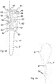
Fig. 1 einen Musiker mit einer Tragevorrichtung zum Tragen eines Blasinstruments wie zum Beispiel eines Saxophons, an der eine erste Ausführung der Vorrichtung gemäss der Erfindung zum Einsatz kommen kann, -
Fig. 2 und 3 die Tragevorrichtung ausFigur 1 allein mit einer Kordel zur Befestigung an einem Musikinstrument sowie Tragriemen für den Nacken, sowie mit der erfindungsgemässen Vorrichtung zur Längenverstellung der Kordel, -
Fig. 4 ein becherförmiger, erster Teil der erfindungsgemässen Vorrichtung gemässFigur 2 und 3 zur Längenverstellung der Kordel in einer Ansicht in Perspektive, -
Fig. 5a ein Einsatz der Vorrichtung nachFigur 2 und 3 in einer ersten Ansicht in Perspektive von unten, -
Fig. 5b der Einsatz vonFigur 5a in einer zweiten Ansicht in Perspektive von oben, -
Fig. 6a eine Ansicht des Einsatzes ausFigur 5a und 5b eingesetzt im ersten Teil in einem Schnitt auf halber Höhe durch den Einsatz sowie darin angeordnete Kordelstücke, die durch die Öse eines Hakens geführt sind, -
Figur 6b den Einsatz und ersten Teil ausFigur 6a ohne die Kordelstücke, -
Figur 6c eine vergrösserte Ansicht des Einsatzes und ersten Teil vonFigur 6a , -
Figur 7 eine Ansicht eines Schnitts der erfindungsgemässen Vorrichtung mit zusammengesetztem ersten Teil und Einsatz, wobei der Schnitt auf Höhe des oberen Rands des becherförmigen Teils und der Führungsnuten des Einsatzes liegt, -
Figur 8 eine Ansicht gemäss dem Schnitt VIII-VIII inFigur 7 der Vorrichtung mit den beiden ineinander gesetzten Teilen und einem Kordelstück, das bei entspannter Feder festgeklemmt ist. - Zudem zeigen
Figuren 9-14
eine Variante der ersten Ausführung der erfindungsgemässen Vorrichtung. - Davon zeigen:
-
Figur 9 eine Tragevorrichtung mit einer Kordel zur Befestigung an einem Musikinstrument und Trageriemen für den Nacken sowie mit der Variante der ersten Ausführung der erfindungsgemässen Vorrichtung zur Längenverstellung der Kordel, -
Figur 10 ein becherförmiger, erster Teil der Variante der ersten Ausführung der erfindungsgemässen Vorrichtung gemässFigur 9 in einer Ansicht in Perspektive von oben, -
Fig. 11a ein Einsatz der Vorrichtung nachFigur 9 in einer ersten Ansicht in Perspektive von oben, -
Fig. 11b den Einsatz vonFigur 9 in einer zweiten Ansicht in Perspektive von unten, -
Fig. 12 eine Ansicht in Perspektive des Einsatzes ausFigur 11a und 11b eingesetzt im ersten Teil in einem Schnitt unterhalb des oberen Rands des Einsatzes, -
Figur 13a eine Ansicht in Perspektive des Einsatzes ausFigur 12 eingesetzt im ersten Teil in einem Schnitt auf halber Höhe durch den Einsatz sowie darin angeordnete Kordelstücke, -
Figur 13b eine Ansicht von oben des Einsatzes ausFigur 12 eingesetzt im ersten Teil in einem Schnitt auf halber Höhe durch den Einsatz sowie darin angeordnete Kordelstücke, -
Figur 14 eine Ansicht gemäss dem Schnitt XIV-XIV inFigur 13b der Vorrichtung mit den beiden ineinander gesetzten Teilen und einem Kordelstück, das bei entspannter Feder festgeklemmt ist. -
Figur 15 ein Beispiel einer zweiten Ausführung der Erfindung, eine Vorrichtung zur Längenverstellung von Bändern oder Flachkordeln. -
Figur 16 einen Querschnitt entlang A-A der Vorrichtung vonFigur 15 um eine vertikale Achse gedreht. -
Figur 17 den Einsatz der Vorrichtung vonFigur 15 mit eingelegten Bändern. -
Figur 18 eine Vergrösserung des Querschnitts ausFigur 16 . -
Figur 19 die Vorrichtung gemäss zweiter Ausführung mit Tragegurt. -
Figur 20 den Einsatz der Vorrichtung ausFigur 15 . -
Figur 21 den becherförmigen Teil der Vorrichtung ausFigur 15 . -
Figur 22 die Form der übereinander gelegten Bänder, wenn in die Vorrichtung ausFigur 15 gelegt. - In den Figuren sind für dieselben Elemente jeweils dieselben Bezugszeichen verwendet worden und erstmalige Erklärungen betreffen alle Figuren, wenn nicht ausdrücklich anders erwähnt.
-
Figuren 1 bis zeigen eine Tragevorrichtung 1 für beispielsweise ein Saxophon oder ähnliches Blasinstrument M mit Trageriemen 2 (auch Tragegurt genannt), die der Musiker um den Nacken trägt und an dessen Enden eine Kordel 4 befestigt ist. Die Kordel 4 führt in eine erfindungsgemässe Vorrichtung 3 zur Längenverstellung der Kordel 4, wobei die Kordel 4 am unteren Ende der Vorrichtung 3 wieder herausführt und in doppelter Schlinge durch die Öse eines Hakens 5 geführt ist. Der Haken 5 lässt sich am Musikinstrument M einhaken und befestigenFigur 3 zeigt die Tragevorrichtung 1 etwas vergrössert und insbesondere zwei Teile der Vorrichtung 3, einen äusseren ersten Teil 10 und einen inneren zweiten Teil 20. Einfach geführte Kordelstücke 4 führen vom Trageriemen 2 durch Öffnungen in den Teilen 10 und 20 am oberen Ende der Vorrichtung 3 in diese hinein. Doppelt geführte Kordelstücke 4 führen durch weitere Öffnungen in den Teilen 10 und 20 am unteren Ende der Vorrichtung 3 zur Öse 5' des Hakens 5. -
Figur 4 zeigt einen becherförmigen, ersten Teil 10 der erfindungsgemässen Vorrichtung aus denFiguren 1-3 , der in der gezeigten Ausführung rund gebildet ist und einen runden Boden 11 mit umlaufendem Rand 12 aufweist. An einer Stelle des umlaufenden Rands 12 ist eine Ausnehmung 13 für die Aufnahme eines doppelt geführten Kordelstücks angeordnet, das durch eine Nut mit Kehrtwendung im Einsatz, wie inFigur 5a gezeigt, geführt werden kann. Beidseits der Ausnehmung 13 sind zwei Öffnungen 14 angeordnet, durch die jeweils ein weiteres Kordelstück hindurch geführt werden kann. Gegenüber von den zwei Öffnungen 14 sind im umlaufenden Rand 12 zwei weitere Öffnungen 15 angeordnet, durch die die genannten Kordelstücke aus der erfindungsgemässen Vorrichtung herausgeführt werden können. In der Mitte im Innern des becherförmigen Teils 10 ist in dieser Ausführung ein Stift 16 angeordnet, der einer Positionierung einer Spiralfeder dient. -
Figuren 5a und b zeigen einen Einsatz 20, der in den becherförmigen Teil ausFigur 4 eingesetzt werden kann. Der Einsatz 20 ist in seiner Form der Becherform des ersten Teils 10 angepasst und weist eine obere Fläche 21 und umlaufende Fläche 22 auf. An der umlaufenden Fläche 22 ist eine Ausnehmung 23 angeordnet. Wird der Einsatz 20 in den ersten Teil 10 eingesetzt, so wird der Einsatz 20 vom umlaufenden Rand 12 umschlossen und die Ausnehmungen 13 und 23 der beiden Teile 10 und 20 stimmen in ihrer Position überein.
Der Einsatz 20 weist eine Nut 24 auf, die sich von der Ausnehmung 23 weg erstreckt und eine Kehrtwendung in der Form eines U's oder eine andere ähnliche Wendung bildet, wobei die Wendung etwa 180° beträgt. In der Mitte des Einsatzes 20, umschlossen von der Nut 24, befindet sich ein Mittelteil 25 mit einer Vertiefung, in die eine Feder 26 platziert werden kann. Beim Einsetzen des Einsatzes 20 in den becherförmigen Teil 10 greift der Stift 16 in die Vertiefung sowie in die Feder 26 ein.
Der Einsatz 20 weist zudem in der umlaufenden Fläche 22 in symmetrischer Anordnung zwei seitliche Führungsnuten 28 auf, die beidseits der Ausnehmung 23 beginnen und sich um einen Teil des Einsatzes 20 entlang der Fläche 22 erstrecken, wobei deren Enden sich vorzugsweise an der der Ausnehmung 23 gegenüberliegenden Seite des Einsatzes 20 befinden. Die Führungsnuten 28 dienen der Führung von Kordelstücken. Sie weisen erfindungsgemäss Elemente zur Umlenkung und Hemmung der Bewegung von Kordeln auf. In der gezeigten Ausführung sind diese Elemente in der Form von abgeschrägten Flächen 29, die aufeinander zuführen und in einer Spitze 29' aufeinander treffen.
In denFiguren 6a-c ist die Zusammensetzung der beiden Teile 10 und 20 dargestellt, wobei die Vorrichtung 3 aufgeschnitten gezeigt ist.Figur 6a und c zeigt zudem die Anordnung von Kordelstücken in der erfindungsgemässen Vorrichtung 3.
Zunächst wird ein Kordelstück 4a in den Einsatz 20, insbesondere in die Nut 24 mit der Kehrtwendung und um den Mittelteil 25 eingelegt. Die zwei Enden des Kordelstücks 4a führen sodann durch die Ausnehmung 23 des Einsatzes 20 sowie die Ausnehmung 13 des becherförmigen Teils 10 aus der Vorrichtung 3 heraus und werden durch die Öse 5' des Hakens 5 hindurchgeschnürt. Nach der Öse 5' führen die beiden Kordelstücke, nunmehr mit 4b bezeichnet, zurück zur Vorrichtung 3 und durch die Öffnungen 14 des becherförmigen Teils 10 und entlang den Führungsnuten 28 des Einsatzes 20. Die Kordelstücke 4b führen sodann an der gegenüberliegenden Seite aus den Führungsnuten 28 des Einsatzes 20 heraus und durch die Öffnungen 15 des becherförmigen Teils 10 aus der Vorrichtung 3 wieder hinaus. Danach führen die Kordelstücke, nunmehr mit 4c bezeichnet, zu einem Trageriemen oder einem Tragegestell wie inFigur 1-3 gezeigt. In den Führungsnuten 28 werden die Kordelstücke entlang den beiden zueinander laufenden Flächen 29 und um die Fläche 29' herum geführt, welche die Flächen 29 verbindet, wobei die Kordelstücke an der äusseren Seite der Nut 28 von der Innenfläche des umlaufenden Rands 12 des becherförmigen Teils 10 geführt sind. Die Eigenart der Erfindung ist die separate Führung der Kordelstücke 4a und 4b, indem diese durch separierte Öffnungen bzw. Ausnehmungen 13, 14 und 23 führen und das Kordelstück in der Nut 24 mit Kehrtwendung die Kordelstücke in den seitlichen Nuten 28 nicht berühren.
Wird die Länge der Kordel verändert, so wird die Länge der Kordelstücke 4a und 4b verändert, d.h. die Länge der doppelt geführten Kordel wird verlängert oder verkürzt. Entsprechend verändert sich auch die Länge des einfach geführten Stücks 4c. Bei einer Längenverstellung bleibt jedoch der Teil der Kordel, der in der Nut 24 mit Kehrtwendung sich befindet, stets an Ort. Es bewegen sich nur die Teile der Kordel, die durch die Führungsnuten 28 führen. Die Vorrichtung 3 lässt sich entlang der Kordelstücke in den Führungsnuten 28 bewegen, wenn der Einsatz 20 in den becherförmigen Teil 10 entgegen der Kraft der Feder 26 hineingedrückt wird, sodass die Öffnungen 14 und 15 mit den Ein- und Ausgängen der Führungsnuten 28 am meisten übereinstimmen. Dann lässt sich die Vorrichtung 3 nach oben oder unten bewegen bzw. die Kordellänge verkürzen oder verlängern. Wird der Druck auf den Einsatz 20 und auf die Feder 26 nachgelassen, so entspannt sich die Feder und der Einsatz 20 bewegt sich wieder etwas aus dem becherförmigen Teil 10 heraus. Dabei verengen sich die Ein- und Ausgänge der Führungsnuten 28 und die Kordelstücke werden zwischen den beiden Teilen 10 und 20 fest geklemmt.
Figur 8 zeigt die Vorrichtung 3 in einem Schnitt gemäss VIII-VIII inFigur 7 und stellt den Mechanismus des Festklemmens der Kordelstücke in der Vorrichtung 3 dar, wenn die Feder 26 entspannt ist. Nachdem die gewünschte Länge der Kordel ausgewählt worden ist, wird der Einsatz 20 durch die Feder 26 etwas aus dem becherförmigen Teil 10 herausgestossen. Dabei bewegt sich die Führungsnut 28 ebenfalls, sodass deren Ein- und Ausgänge über die Höhe der Öffnungen 14 und 15 des becherförmigen Teils 10 sich bewegen, und die Kordel 4 in der Führungsnut 28 wird zwischen dem Rand 14' und 15' der Öffnungen 14 bzw. 15 und der einen Fläche 28' der Führungsnut 28 im Einsatz 20 geklemmt. Dadurch wird die Bewegung der Kordel 4 arretiert.
Die Elemente zur Umlenkung der Kordel in den Führungsnuten, d.h. die schräg aufeinander führenden Flächen 29 der Führungsnuten 28 bewirken durch die Reibung, dass sich die Position der erfindungsgemässen Vorrichtung unter dem Gewicht des Musikinstruments nicht verändern kann. Bei grösserem Gewicht des Musikinstruments erhöht sich auch die Reibung in der Umlenkung. Die Feder 26 zwischen dem becherförmigen Teil 10 und dem Einsatz 20 der Vorrichtung dient hauptsächlich der Arretierung der Vorrichtung, wenn das Musikinstrument vom Musiker hoch gehalten wird und die Kordel nicht gespannt ist und die Umlenkung keine Reibung erzeugt. -
Figuren 9-14 zeigen eine Variante der ersten Ausführung der erfindungsgemässen Vorrichtung 3'. Sie weist wiederum einen ersten, becherförmigen Teil 30 und einen darin einsetzbaren Einsatz 40 auf. Die Funktionsweise dieser Variante ist gleich wie die der Vorrichtung 3 ausFiguren 1-8 . Die Form des becherförmigen Teils 30 sowie des Einsatzes 40 ist in dieser Variante eckig. Der Teil 30, wie inFigur 10 gezeigt, mit einem Boden 31 und umlaufenden Rand 32 weist wiederum im Rand 32 eine Ausnehmung 33 sowie je zwei Öffnungen 34 und 35 auf, durch die die Kordel geführt wird. Die zwei Öffnungen 34 sind beidseits der Ausnehmung 33 angeordnet, wobei die zwei weiteren Öffnungen 35 an der gegenüberliegenden Seite des Teils 30 liegen. In der Mitte des becherförmigen Teils 30 ist wiederum ein Stift 36 für die Positionierung einer Feder angeordnet.
Der dazugehörige Einsatz 40, wie inFiguren 11a und b gezeigt, mit einer oberen Fläche 41 und umlaufenden Seitenfläche 42 weist an einer Stelle eine Ausnehmung 43 auf, die in eine Nut 44 mit einer Kehrtwendung führt, wobei in der Mitte, umschlossen von der Nut ein Mittelteil 45 angeordnet ist. Der Mittelteil 45 besitzt eine Ausnehmung, in die die Feder 26 eingesetzt werden kann. Der Einsatz 40 weist beidseits der Ausnehmung 43 je eine seitlich verlaufende Führungsnut 48 auf, durch die eine Kordel geführt werden kann.
Bei zusammengesetzten Teilen 30 und 40 stimmen die Positionen der beiden Ausnehmungen 33 und 43 überein. Ebenso stimmen die Positionen der vier Öffnungen 34 und 35 des becherförmigen Teils 30 mit den Ein- und Ausgängen der Führungsnuten 48 des Einsatzes 40 überein. Bei der zusammengesetzten Vorrichtung 3', wie in derFigur 13a und b gezeigt, ist die Kordel wiederum in die Nut 44 mit Kehrtwendung platziert und durch die Ausnehmung 43 des Einsatzes 40 und durch die Ausnehmung 33 des becherförmigen Teils 30 geführt.
Die Elemente zur Hemmung und Umlenkung der Kordel in den Führungsnuten sind in diesem Ausführungsbeispiels durch Vorsprünge 37 im becherförmigen Teil 30 ausgebildet, die durch entsprechend positionierte Ausnehmungen 47 im Einsatz 40 eingreifen und in die Führungsnuten 48 hineinragen. Die Vorsprünge 37 sind in derFigur 10 und12 dargestellt. Die entsprechenden Ausnehmungen 47 in den Führungsnuten 48 des Einsatzes 40 sind in denFiguren 11a und b gezeigt und inFigur 13a angedeutet. Dabei führen die Kordelstücke 4a und 4b zu einem Musikinstrument und die Kordelstücke 4c wiederum zu einem Trageriemen oder Tragegestell am Musiker. Die in den Führungsnuten 48 platzierten Kordelstücke werden über die Vorsprünge 37 geführt und dadurch umgelenkt, wie es in derFigur 13b gezeigt ist. Die Umlenkung ist in diesem Beispiel in der Richtung senkrecht zum Boden 31 des Teils 30 und der Fläche 41 des Einsatzes 40. Im Beispiel gemäss denFiguren 1-9 ist die Umlenkung hingegen in einer Richtung parallel zu den Bodenflächen 11 und 21 der beiden Teile 10 und 20. Deren Funktion der Bewirkung einer Reibung zur Erhöhung der Stabilität der Vorrichtung ist in beiden Ausführungsbeispielen die gleiche. -
Figur 14 zeigt in einem Querschnitt die Umlenkung der Kordel 4 mittels der Vorsprünge 37, die durch die Ausnehmung 47 in die Führungsnut 48 hineinragt. Die Figur zeigt die Situation mit gepresster Feder. Wird die Feder entspannt, so hebt sich der Einsatz 40 und die Kordel wird, wie beim Beispiel inFigur 8 , zwischen dem oberen Rand 34' und 35' der Öffnung 34 bzw. 35 und der unteren Fläche 48' der Führungsnut 48 eingeklemmt und arretiert. -
Figur 15 zeigt die Vorrichtung 50 gemäss der zweiten Ausführung für die Verwendung mit Flachkordeln Bändern. Die Vorrichtung 50 zur Längenverstellung von Bändern oder Flachkordeln 4', 4" weist wiederum einen äusseren, becherförmigen Teil 51 und einen Einsatz 52 auf. Die Bänder 4', 4", beispielsweise gewobene Bänder, führen durch eine Öse 5' mit einem Haken 5, der an einem Musikinstrument, z.B. einem Saxophon, befestigt werden kann. -
Figur 16 zeigt die Führung der Bänder 4', 4" durch die beiden Teile 51 und 52. Hierzu weist der becherförmige Teil 51 eine Eingangsöffnung 53 und der Einsatzteil eine erste Öffnung 54 und eine zweite, gegenüberliegende Öffnung 55 auf. Diese haben einen länglichen Querschnitt, der einem Band angepasst ist. Die Enden der Bänder 4', 4" werden im Einsatzteil 52 in einer Nut mit einer Ausnehmung gehalten, durch die die Bänder 4', 4" herausgeführt werden. Der Einsatz 52 weist zudem einen Kanal 56 auf, in diesem Fall einen Durchgang 56. -
Figur 17 zeigt den Einsatzteil 52 mit einer Ausnehmung 57, in die zwei aufeinander gelegte Bänder 4', 4" hineingelegt werden, die eine Nut 58 mit einer Kehrtwendung in der Form eines U führt. Die Nut 58 wird durch den umlaufenden Rand 59 des Einsatzes 52 und einen Mittelteil 60 gebildet. Im Mittelteil 60 befindet sich eine Vertiefung 61 für den Einsatz einer Feder 62 (sieheFigur 18 ). Die Bänder 4', 4" weisen nahe ihren Enden ein Loch auf, das über den Mittelteil 60 mit der Feder 62 gelegt wird, wodurch die Bänder dort festgehalten sind. -
Figur 18 zeigt die Führung der Bänder 4', 4" in den beiden Teilen 51 und 52. Die beiden Bänder 4', 4" sind in der Nut 58 angeordnet, indem ihr Loch über dem Mittelteil 62 platziert ist, wobei der Mittelteil 62 in eine Vertiefung 62' im Boden des becherförmigen Teils 51 eingreift. Die Bänder 4', 4" führen von der Nut 58 durch die Ausnehmung 57 des Einsatzes 52 durch die Eingangsöffnung 53 im becherförmigen Teil 51 aus der Vorrichtung 50 hinaus. Nach Durchlaufen einer Öse (wie inFigur 15 gezeigt) führen die Bänder durch die erste Öffnung 54 des becherförmigen Teils 51 in die Vorrichtung 50 hinein und durch den Eingang 63 in den Durchgang 56 im Einsatz 52 hinein. Im Durchgang 56 werden die Bänder 4', 4" über Elemente zur Hemmung ihrer Bewegung geführt, die in diesem Beispiel durch zueinander angewinkelte Flächen 64 und 65 ausgebildet sind, die über eine weitere Fläche miteinander verbunden sind. Über einen Ausgang 66 des Durchgangs 56 führen die Bänder zur zweiten Öffnung 55 des becherförmigen Teils 51 aus der Vorrichtung hinaus. Die beiden Bänder 4', 4" führen sodann zu einem Tragegurt 2 wie inFigur 19 gezeigt, der sich um den Nacken eines Musikers legen lässt. -
Figur 20 zeigt den Einsatzteil 52 in Perspektive mit der Nut 58 mit Mittelteil 60 zur Festhaltung der Bänder. Im Mittelteil 60 ist die Vertiefung 61 zur Platzierung einer Feder gezeigt. Eine Ausnehmung 57 im umlaufenden Rand 59 des Einsatzteils 51 führt in die Nut und aus der Nut 58 heraus. Neben der Ausnehmung 57 und getrennt von der Ausnehmung 57 ist der Eingang 63 zum Durchgang 56 angeordnet. Zudem sind im Durchgang 56 die zueinander angewinkelten Flächen 64 und 65 gezeigt, welche die Bewegung der Bänder durch den Durchgang hemmen. Der Ausgang 66 aus dem Durchgang 56 befindet sich an der hinteren Seite des Einsatzteils 52. -
Figur 21 zeigt den becherförmigen, äusseren Teil 52 in Perspektive und insbesondere in seiner umlaufenden Wand 70 die Eingangsöffnung 53 sowie die davon getrennte erste Öffnung 54. Die zweite Öffnung 55 befindet sich an der hinteren Seite des becherförmigen Teils 51. Die Öffnungen 53, 54 und 55 stimmen beim Zusammensetzen der beiden Teile 51 und 52 mit der Ausnehmung 57 bzw. mit dem Eingang 63 bzw. mit dem Ausgang 66 des Durchgangs 56 überein. D.h. bei entspannter Feder stimmen diese Öffnungen zum Teil miteinander überein, sodass die Bänder in den Öffnungen festgeklemmt werden. Bei zusammengedrückter Feder stimmen diese Öffnungen in ihren Querschnitten vollständig miteinander überein, sodass die Bänder bewegt werden können. Im Boden des äusseren Teils 52 ist die Vertiefung 62' angeordnet, in die der Mittelteil 60 hineinpasst. -
Figur 22 zeigt die Form der Bänder 4', 4" wie sie übereinander gelegt in der Vorrichtung 50 liegen würden. Nahe ihren Enden weisen sie ein Loch 67 auf, das über den Mittelteil 60 gelegt werden kann. -
- 1 Tragevorrichtung zum Tragen eines Musikinstruments
- 2 Trageriemen/Tragegurt
- 3 Vorrichtung zur Längenverstellung einer Kordel
- 3' Variante der ersten Ausführung der Vorrichtung zur Längenverstellung einer Kordel
- 4 Kordel
- 4a,b,c Kordelstück
- 4', 4" Flachkordel, Band
- 5 Haken
- 5' Öse
- 10 erster, äusserer Teil der Vorrichtung zur Längenverstellung, becherförmiger Teil
- 11 Boden des ersten Teils
- 12 umlaufender Rand des ersten Teils
- 13 Ausnehmung
- 14 Öffnungen am unteren Rand des ersten Teils
- 15 Öffnungen am oberen Rand des ersten Teils
- 16 Stift
- 20 zweiter, innerer Teil der Vorrichtung zur Längenverstellung, Einsatzteil
- 21 obere Fläche des zweiten Teils, Einsatzteils
- 22 umlaufende Fläche des zweiten Teils
- 23 Ausnehmung
- 24 Nut mit Kehrtwendung
- 25 Mittelteil der Nut 24 mit Ausnehmung für Feder
- 26 Feder
- 27 seitliche Führungsnut
- 28 innere Wandung von seitlicher Führungsnut
- 28' Fläche der Führungsnut 28
- 29 Element zur Umlenkung /Hemmung der Bewegung der Kordel
- 29' Verbindung zwischen Flächen 29
- 30 becherförmiger, erster Teil
- 31 Boden
- 32 umlaufender Rand
- 33 Ausnehmung
- 34 Öffnungen am unteren Ende
- 35 Öffnungen am oberen Ende
- 36 Stift
- 37 Element zur Hemmung der Bewegung der Kordel, Vorsprung
- 40 Einsatzteil
- 41 obere Fläche
- 42 umlaufende Randfläche
- 43 Ausnehmung
- 44 Führungsnut mit Kehrtwendung
- 45 Mittelteil der Nut mit Ausnehmung für Feder
- 47 Ausnehmung für Vorsprung 37
- 48 seitliche Führungsnut
- 48' Fläche der Führungsnut 48
- 50 Vorrichtung zweite Ausführung
- 51 becherförmiger Teil
- 52 Einsatzteil
- 53 Eingangsöffnung
- 54 erste Öffnung
- 55 zweite Öffnung
- 56 Durchgang
- 57 Ausnehmung
- 58 Nut
- 59 umlaufender Rand
- 60 Mittelteil
- 61 Vertiefung
- 62 Feder
- 63 Eingang zu Durchgang
- 64 angewinkelte Fläche
- 65 angewinkelte Fläche
- 66 Ausgang aus Durchgang
- 67 Loch in Band
Claims (12)
- Eine Vorrichtung (3, 3', 50) zur Längenverstellung einer Kordel (4, 4', 4") weist einen becherförmig ausgebildeten, ersten Teil (10, 30, 51) und einen Einsatz (20, 40, 52) als zweiten Teil auf, wobei die beiden Teile (10, 20, 30, 40, 51, 52) ineinander schiebbar sind und zwischen den beiden Teilen (10, 20, 30, 40, 51, 52) eine Feder (26, 62) angeordnet ist
dadurch gekennzeichnet, dass
der becherförmige, erste Teil (10, 30, 51) in einer umlaufenden Wand (12, 32, 70) eine Ausnehmung oder Eingangsöffnung zwecks Hindurchführung (13, 33, 53) von zwei Kordelstücken oder zwei Bändern (4, 4a, 4', 4") sowie mindestens zwei weitere Öffnungen (14, 15, 34, 35, 54, 55) für zwei Kordelstücke oder zwei Bänder (4, 4b, 4c, 4', 4") aufweist, wobei die erste der mindestens zwei Öffnungen (14, 34, 54) neben der Ausnehmung oder Eingangsöffnung (13, 33, 53) und weitere Öffnungen (15, 35, 55) gegenüberliegend von der ersten Öffnung (14, 34, 54) im umlaufenden Rand (12, 32, 70) angeordnet sind,
wobei der Einsatz (20, 40, 52) eine Nut (24, 44, 58) mit einer Kehrtwendung aufweist, die durch einen umlaufenden Rand (22, 42, 59) des Einsatzes (20, 40, 52) und einen Mittelteil (25, 45, 60) gebildet wird, und der umlaufende Rand (22, 42, 59) eine Ausnehmung (23, 43, 57) aufweist, die in die Nut (24, 44, 58) hineinführt, und der Einsatz (20, 40, 52) mindestens einen Kanal (28, 48, 56) für je ein Kordelstück oder für ein Band (4, 4', 4") aufweist, wobei der Kanal (28, 48, 56) jeweils Elemente (64, 65, 29) zur Umlenkung und zur Hemmung der Bewegung einer Kordel oder eines Bands aufweist und der mindestens eine Kanal (28, 48, 56) von der Nut (24, 44, 58) mit der Kehrtwendung vollständig getrennt ist. - Vorrichtung (3, 3') nach Anspruch 1
dadurch gekennzeichnet, dass
der becherförmige, erste Teil (10, 30) in einer umlaufenden Wand (12, 32) eine Ausnehmung (13, 33) für zwei Kordelstücke (4, 4a) sowie vier weitere Öffnungen (14, 15, 34, 35) für je ein Kordelstück (4, 4b, 4c) aufweist, wobei die erste und zweite Öffnung (14, 34) dieser vier weiteren Öffnungen beidseitig der Ausnehmung (13, 33) und die dritte und vierte Öffnung (15, 35) gegenüberliegend von der ersten und zweiten Öffnung (14, 34) im umlaufenden Rand (12, 32) angeordnet sind,
wobei der Einsatz (20, 40) eine Nut (24, 44) mit einer Kehrtwendung aufweist, die durch einen umlaufenden Rand (22, 42) des Einsatzes (20, 40) und einen Mittelteil (25, 45) gebildet wird, und der umlaufende Rand (22, 42) eine Ausnehmung 23, 43) aufweist, die in die Nut (24, 44) hineinführt, und der Einsatz (20, 40) an der Aussenseite seines umlaufenden Rands (22, 42) und beidseits der Ausnehmung (23, 43) je eine Führungsnut (28, 48) für je ein Kordelstück (4) aufweist und die beiden Führungsnuten (28, 48) Elemente (29, 29', 37, 47) zur Umlenkung und Hemmung der Bewegung einer Kordel (4) in den Führungsnuten (28, 48) aufweisen, und die seitlichen Führungsnuten (28, 48) von der Nut (24, 44) mit der Kehrtwendung vollständig getrennt sind. - Vorrichtung (3, 3') nach Anspruch 2
dadurch gekennzeichnet, dass
der Einsatz (20, 40) in seinem Mittelteil (25, 45) eine Ausnehmung zur Aufnahme der Feder (26) aufweist. - Vorrichtung (3) nach Anspruch 2 oder 3
dadurch gekennzeichnet, dass
die Elemente zur Hemmung der Bewegung einer Kordel (4) durch die Führungsnuten (28) durch zueinander angewinkelte Flächen (29) ausgebildet sind. - Vorrichtung (3') nach Anspruch 2 oder 3
dadurch gekennzeichnet, dass
die Elemente zur Umlenkung und Hemmung der Bewegung einer Kordel (4) durch die Führungsnuten (48) Vorsprünge (37) im becherförmigen, ersten Teil (30) und Ausnehmungen (47) im Einsatz (40) umfassen, wobei die Vorsprünge (37) im Innern des becherförmigen, ersten Teils (30) sich senkrecht von dessen Bodenfläche weg erstrecken und die Ausnehmungen (47) im Einsatz (40) in dessen umlaufenden Rand 42) angeordnet sind und die Vorsprünge (37) in die Ausnehmungen (47) eingreifen und in die Führungsnuten (48) hineinragen. - Vorrichtung (3, 3') nach einem der Ansprüche 3-5
dadurch gekennzeichnet, dass
der becherförmige Teil (10, 30) in seinem Innern einen Stift (16, 36) zur Fixierung der Position sowie Ausrichtung der Feder (26) und der Einsatz (20, 40) in seinem Mittelteil (25, 45) eine Ausnehmung aufweist, in die der Stift (16, 36) eingreift. - Vorrichtung (50) nach Anspruch 1
dadurch gekennzeichnet, dass
der becherförmige, erste Teil (51) eine Eingangsöffnung (53) zwecks Hindurchführung von zwei Kordelstücken oder von zwei Bändern (4', 4") aufweist und an seinem umlaufenden Rand (70) zwei weitere Öffnungen (54, 55) angeordnet sind, wovon die erste Öffnung (54) neben der Eingangsöffnung (53) und die zweite Öffnung (55) gegenüberliegend der ersten Öffnung (54) am umlaufenden Rand (70) des becherförmigen Teils (51) angeordnet ist und der Einsatz (52) einen als Durchgang (56) ausgebildeten Kanal aufweist, der von einem Eingang (63) neben der Eingangsöffnung (53) zu einem dem Eingang (63) gegenüberliegenden Ausgang (66) führt, wobei der Durchgang (56) Elemente (64, 65) zur Umlenkung und Hemmung der Bewegung von Kordeln oder von Bändern aufweist und die Nut (58) vollständig vom Eingang (63) des Kanals (56) vollständig getrennt ist. - Vorrichtung (50) nach Anspruch 7
dadurch gekennzeichnet, dass
der Einsatz (52) in seinem Mittelteil (60) eine Ausnehmung (61) zur Aufnahme der Feder (62) aufweist. - Vorrichtung (50) nach Anspruch 7 oder 8
dadurch gekennzeichnet, dass
die Elemente zur Hemmung der Bewegung einer Kordel (4', 4") durch den Durchgang (56) durch zueinander angewinkelte Flächen (64, 65) ausgebildet sind. - Vorrichtung (50) nach einem der Ansprüche 7-9
dadurch gekennzeichnet, dass
der becherförmige Teil (51) in seinem Innern einen Stift zur Fixierung der Position sowie Ausrichtung der Feder (62) und der Einsatz (52) in seinem Mittelteil (60) eine Ausnehmung (61) aufweist, in die der Stift eingreift. - Tragevorrichtung (1) für das Tragen eines Musikinstruments (M) mit einer Vorrichtung (3, 3, 50) gemäss einem der Ansprüche 1-10 sowie mit einem Trageriemen (2) für den Nacken oder einem Tragegestell für Schultern, einer Kordel (4) sowie einer Befestigung (5) der Kordel oder des Bands (4) am Musikinstrument (M).
- Tragevorrichtung (1) nach Anspruch 11,
wobei die Befestigung der Kordel (4) am Musikinstrument (M) ein Haken (5) mit einer Öse (5') ist.
Applications Claiming Priority (1)
| Application Number | Priority Date | Filing Date | Title |
|---|---|---|---|
| CH00014/19A CH715715A1 (de) | 2019-01-09 | 2019-01-09 | Verstellbare Tragevorrichtung für ein Musikinstrument. |
Publications (2)
| Publication Number | Publication Date |
|---|---|
| EP3680892A1 true EP3680892A1 (de) | 2020-07-15 |
| EP3680892B1 EP3680892B1 (de) | 2022-11-30 |
Family
ID=69137810
Family Applications (1)
| Application Number | Title | Priority Date | Filing Date |
|---|---|---|---|
| EP20150378.6A Active EP3680892B1 (de) | 2019-01-09 | 2020-01-06 | Verstellbare tragevorrichtung für ein musikinstrument |
Country Status (6)
| Country | Link |
|---|---|
| US (1) | US10964297B2 (de) |
| EP (1) | EP3680892B1 (de) |
| JP (1) | JP7427224B2 (de) |
| CN (1) | CN111429867A (de) |
| CH (1) | CH715715A1 (de) |
| ES (1) | ES2934585T3 (de) |
Families Citing this family (3)
| Publication number | Priority date | Publication date | Assignee | Title |
|---|---|---|---|---|
| CH715715A1 (de) * | 2019-01-09 | 2020-07-15 | Jancic Silvin | Verstellbare Tragevorrichtung für ein Musikinstrument. |
| US11122867B1 (en) * | 2019-09-08 | 2021-09-21 | Productive Collaboration, LLC | Push button slide mechanism and method of assembling the same |
| US11132982B1 (en) * | 2020-11-25 | 2021-09-28 | Michael Drapkin | Bass clarinet body strap |
Citations (6)
| Publication number | Priority date | Publication date | Assignee | Title |
|---|---|---|---|---|
| US1637003A (en) | 1925-12-09 | 1927-07-26 | Lang Albion Slayton | Saxophone cord |
| US2561606A (en) * | 1946-09-06 | 1951-07-24 | Norman C Bates | Sazophone halter |
| US3225984A (en) * | 1964-07-06 | 1965-12-28 | Hyman Raymond | Support for saxophones and similar musical instruments |
| DE3225476A1 (de) * | 1981-07-14 | 1983-02-03 | Jaquith, Hope, Laguna Niguel, Calif. | Musikinstrumentenhalter |
| KR20030091837A (ko) * | 2003-07-26 | 2003-12-03 | 안태진 | 휴대품 장착용 목걸이 |
| CH704201A2 (de) | 2010-12-13 | 2012-06-15 | Silvin M Jancic | Tragevorrichtung für ein Blasinstrument. |
Family Cites Families (29)
| Publication number | Priority date | Publication date | Assignee | Title |
|---|---|---|---|---|
| US1586251A (en) * | 1925-09-19 | 1926-05-25 | Lang Albion Slayton | Saxophone-supporting cord |
| US1891947A (en) * | 1929-08-08 | 1932-12-27 | Edward V Powell | Support for saxophones and similar musical instruments |
| US1789184A (en) * | 1929-11-26 | 1931-01-13 | Albion S Lang | Saxophone cord |
| US2615324A (en) * | 1950-06-08 | 1952-10-28 | Hickok Mfg Co Inc | Key ring |
| US3057526A (en) * | 1959-04-27 | 1962-10-09 | Jaquith Douglas | Musical instrument support |
| DE1231864B (de) * | 1962-09-24 | 1967-01-05 | Max Schmidt | Christbaum- bzw. Dekorationskugel mit eingebautem Spielwerk |
| DE1186738B (de) * | 1963-01-30 | 1965-02-04 | Gauthier Gmbh A | Photographische Kamera mit einem Drahtausloeser |
| US4005765A (en) * | 1973-04-25 | 1977-02-01 | The United States Of America As Represented By The Secretary Of The Navy | Crash load attenuating troop seat |
| US3930289A (en) * | 1974-10-15 | 1976-01-06 | Singular John W | Coupling device |
| JPS6025093Y2 (ja) * | 1980-11-25 | 1985-07-27 | 柳沢管楽器株式会社 | 楽器用ストラップ |
| US4884322A (en) * | 1982-03-30 | 1989-12-05 | Hope Jaquith | Coupling device |
| US4715259A (en) * | 1987-04-06 | 1987-12-29 | Wittman Kenneth L | Strap mounting assembly for electric guitars permitting multiple guitar rotations |
| US4815642A (en) * | 1987-05-15 | 1989-03-28 | Ray Gene S | Ski boot carrier |
| US5437401A (en) * | 1994-02-07 | 1995-08-01 | Seltzer; Richard | Personal harness for carrying articles |
| CA2191657C (en) * | 1996-11-29 | 2006-03-14 | Noel Doyle | Clothes line system with a support system and improved clothes pins |
| US6036066A (en) * | 1998-08-21 | 2000-03-14 | Giacona Container Company | Bottled drink carrier apparatus |
| KR100575176B1 (ko) * | 1998-10-22 | 2006-05-03 | 마르크 에리스만 | 제거 가능한 신체 지지부를 갖는 기타 또는 유사한 악기 |
| US20050258205A1 (en) * | 2004-05-21 | 2005-11-24 | Michaels Of Oregon Co. | Shock-absorbing carrying strap |
| US7888572B2 (en) * | 2007-01-05 | 2011-02-15 | Gibson Guitar Corp. | Guitar strap lock |
| US8051542B2 (en) * | 2008-08-13 | 2011-11-08 | Alexander Buday | Detachable lanyard buckle |
| US7655853B1 (en) * | 2009-01-30 | 2010-02-02 | Ricca Tom L | Weight-relieving device for a woodwind instrument |
| US8534515B2 (en) * | 2011-08-04 | 2013-09-17 | M Group, Inc. | Pivoting elastic shoulder support |
| US20180242668A1 (en) | 2014-04-02 | 2018-08-30 | Troy Earnshaw | A fastening device for a rope-like material used as a part of a belt |
| US9476253B2 (en) * | 2014-04-16 | 2016-10-25 | Yung-Ching Lai | Automatic cord collector of a window blind |
| USD772577S1 (en) * | 2015-01-20 | 2016-11-29 | M Group, Inc. | Elastic shoulder support with shoulder pad and pivot |
| US9492004B1 (en) * | 2015-08-20 | 2016-11-15 | Rick Young | Lightweight suspension harness system for binoculars and method of use |
| US9990910B2 (en) * | 2016-01-15 | 2018-06-05 | D'addario & Company, Inc. | Locking strap mechanism |
| US10070700B1 (en) * | 2017-08-31 | 2018-09-11 | Oculus Vr, Llc | Lanyard adjuster |
| CH715715A1 (de) * | 2019-01-09 | 2020-07-15 | Jancic Silvin | Verstellbare Tragevorrichtung für ein Musikinstrument. |
-
2019
- 2019-01-09 CH CH00014/19A patent/CH715715A1/de unknown
-
2020
- 2020-01-06 ES ES20150378T patent/ES2934585T3/es active Active
- 2020-01-06 EP EP20150378.6A patent/EP3680892B1/de active Active
- 2020-01-08 US US16/737,287 patent/US10964297B2/en active Active
- 2020-01-09 JP JP2020001876A patent/JP7427224B2/ja active Active
- 2020-01-09 CN CN202010024239.8A patent/CN111429867A/zh active Pending
Patent Citations (6)
| Publication number | Priority date | Publication date | Assignee | Title |
|---|---|---|---|---|
| US1637003A (en) | 1925-12-09 | 1927-07-26 | Lang Albion Slayton | Saxophone cord |
| US2561606A (en) * | 1946-09-06 | 1951-07-24 | Norman C Bates | Sazophone halter |
| US3225984A (en) * | 1964-07-06 | 1965-12-28 | Hyman Raymond | Support for saxophones and similar musical instruments |
| DE3225476A1 (de) * | 1981-07-14 | 1983-02-03 | Jaquith, Hope, Laguna Niguel, Calif. | Musikinstrumentenhalter |
| KR20030091837A (ko) * | 2003-07-26 | 2003-12-03 | 안태진 | 휴대품 장착용 목걸이 |
| CH704201A2 (de) | 2010-12-13 | 2012-06-15 | Silvin M Jancic | Tragevorrichtung für ein Blasinstrument. |
Also Published As
| Publication number | Publication date |
|---|---|
| CH715715A1 (de) | 2020-07-15 |
| CN111429867A (zh) | 2020-07-17 |
| JP2020112797A (ja) | 2020-07-27 |
| EP3680892B1 (de) | 2022-11-30 |
| US20200219471A1 (en) | 2020-07-09 |
| JP7427224B2 (ja) | 2024-02-05 |
| ES2934585T3 (es) | 2023-02-23 |
| US10964297B2 (en) | 2021-03-30 |
Similar Documents
| Publication | Publication Date | Title |
|---|---|---|
| EP3680892B1 (de) | Verstellbare tragevorrichtung für ein musikinstrument | |
| AT395803B (de) | Verschnuerung fuer einen schischuh | |
| DE69501922T2 (de) | Schliessvorrichtung, insbesondere für sportschuhe | |
| DE102007062735B3 (de) | Selbstligierendes kieferorthopädisches Bracket | |
| DE102008015583A1 (de) | Kapodaster | |
| EP1086656A2 (de) | Chirurgisches Cerclageband | |
| AT523145B1 (de) | Schuh, insbesondere Einsatzstiefel, mit einem Schuh-Schnürsystem | |
| DE69427276T2 (de) | Tremolovorrichtung | |
| DE19931382C2 (de) | Kinnhalter für ein Musikinstrument | |
| DE3225476A1 (de) | Musikinstrumentenhalter | |
| EP3284082A1 (de) | Klang-deflektor für blasinstrumente | |
| DE10117254C1 (de) | Nagelkorrekturspange | |
| EP3872943A1 (de) | Kabelhaltevorrichtung | |
| DE102011014903B4 (de) | Schnürvorrichtung für einen Schuh | |
| DE102007042183B4 (de) | Halter zum Zusammenhalten einer Vielzahl von länglichen Gegenständen, insbesondere zum Zusammenhalten von Kabeln | |
| AT393106B (de) | Hefteinrichtung fuer blattstapel | |
| DE939785C (de) | Befestigungsschelle | |
| DE102019122136A1 (de) | Kabelbinder | |
| DE19506384C1 (de) | Bindung für das Skispringen oder den Tourenskilauf, insbesondre den Skilauf im Telemark-Stil | |
| DE10326608B4 (de) | Spannvorrichtung zur lösbaren Festlegung eines Klemmgutes | |
| EP2981954B1 (de) | Vorrichtung zum befestigen eines einfachrohrblattes an dem mundstück eines einfachrohrblattblasinstruments | |
| DE102022123402A1 (de) | Haarbinder | |
| AT234988B (de) | Schnurhalter, insbesondere für Jalousien | |
| DE2350382C3 (de) | Vorrichtung mit Zugdrähten zur Einstellung des Biegewinkels einer flexiblen Endoskopspitze | |
| DE4143330C1 (en) | Valve lever for musical instrument - has lever coupled to sprung key and connected to flap valve at other end. |
Legal Events
| Date | Code | Title | Description |
|---|---|---|---|
| PUAI | Public reference made under article 153(3) epc to a published international application that has entered the european phase |
Free format text: ORIGINAL CODE: 0009012 |
|
| STAA | Information on the status of an ep patent application or granted ep patent |
Free format text: STATUS: THE APPLICATION HAS BEEN PUBLISHED |
|
| AK | Designated contracting states |
Kind code of ref document: A1 Designated state(s): AL AT BE BG CH CY CZ DE DK EE ES FI FR GB GR HR HU IE IS IT LI LT LU LV MC MK MT NL NO PL PT RO RS SE SI SK SM TR |
|
| AX | Request for extension of the european patent |
Extension state: BA ME |
|
| STAA | Information on the status of an ep patent application or granted ep patent |
Free format text: STATUS: REQUEST FOR EXAMINATION WAS MADE |
|
| 17P | Request for examination filed |
Effective date: 20201216 |
|
| RBV | Designated contracting states (corrected) |
Designated state(s): AL AT BE BG CH CY CZ DE DK EE ES FI FR GB GR HR HU IE IS IT LI LT LU LV MC MK MT NL NO PL PT RO RS SE SI SK SM TR |
|
| STAA | Information on the status of an ep patent application or granted ep patent |
Free format text: STATUS: EXAMINATION IS IN PROGRESS |
|
| 17Q | First examination report despatched |
Effective date: 20210311 |
|
| GRAP | Despatch of communication of intention to grant a patent |
Free format text: ORIGINAL CODE: EPIDOSNIGR1 |
|
| STAA | Information on the status of an ep patent application or granted ep patent |
Free format text: STATUS: GRANT OF PATENT IS INTENDED |
|
| INTG | Intention to grant announced |
Effective date: 20210927 |
|
| GRAJ | Information related to disapproval of communication of intention to grant by the applicant or resumption of examination proceedings by the epo deleted |
Free format text: ORIGINAL CODE: EPIDOSDIGR1 |
|
| STAA | Information on the status of an ep patent application or granted ep patent |
Free format text: STATUS: EXAMINATION IS IN PROGRESS |
|
| INTC | Intention to grant announced (deleted) | ||
| GRAP | Despatch of communication of intention to grant a patent |
Free format text: ORIGINAL CODE: EPIDOSNIGR1 |
|
| STAA | Information on the status of an ep patent application or granted ep patent |
Free format text: STATUS: GRANT OF PATENT IS INTENDED |
|
| INTG | Intention to grant announced |
Effective date: 20220914 |
|
| GRAS | Grant fee paid |
Free format text: ORIGINAL CODE: EPIDOSNIGR3 |
|
| GRAA | (expected) grant |
Free format text: ORIGINAL CODE: 0009210 |
|
| STAA | Information on the status of an ep patent application or granted ep patent |
Free format text: STATUS: THE PATENT HAS BEEN GRANTED |
|
| AK | Designated contracting states |
Kind code of ref document: B1 Designated state(s): AL AT BE BG CH CY CZ DE DK EE ES FI FR GB GR HR HU IE IS IT LI LT LU LV MC MK MT NL NO PL PT RO RS SE SI SK SM TR |
|
| REG | Reference to a national code |
Ref country code: CH Ref legal event code: EP Ref country code: GB Ref legal event code: FG4D Free format text: NOT ENGLISH |
|
| REG | Reference to a national code |
Ref country code: AT Ref legal event code: REF Ref document number: 1535280 Country of ref document: AT Kind code of ref document: T Effective date: 20221215 |
|
| REG | Reference to a national code |
Ref country code: IE Ref legal event code: FG4D Free format text: LANGUAGE OF EP DOCUMENT: GERMAN |
|
| REG | Reference to a national code |
Ref country code: DE Ref legal event code: R096 Ref document number: 502020002075 Country of ref document: DE |
|
| REG | Reference to a national code |
Ref country code: NL Ref legal event code: FP |
|
| REG | Reference to a national code |
Ref country code: ES Ref legal event code: FG2A Ref document number: 2934585 Country of ref document: ES Kind code of ref document: T3 Effective date: 20230223 |
|
| REG | Reference to a national code |
Ref country code: LT Ref legal event code: MG9D |
|
| PG25 | Lapsed in a contracting state [announced via postgrant information from national office to epo] |
Ref country code: SE Free format text: LAPSE BECAUSE OF FAILURE TO SUBMIT A TRANSLATION OF THE DESCRIPTION OR TO PAY THE FEE WITHIN THE PRESCRIBED TIME-LIMIT Effective date: 20221130 Ref country code: PT Free format text: LAPSE BECAUSE OF FAILURE TO SUBMIT A TRANSLATION OF THE DESCRIPTION OR TO PAY THE FEE WITHIN THE PRESCRIBED TIME-LIMIT Effective date: 20230331 Ref country code: NO Free format text: LAPSE BECAUSE OF FAILURE TO SUBMIT A TRANSLATION OF THE DESCRIPTION OR TO PAY THE FEE WITHIN THE PRESCRIBED TIME-LIMIT Effective date: 20230228 Ref country code: LT Free format text: LAPSE BECAUSE OF FAILURE TO SUBMIT A TRANSLATION OF THE DESCRIPTION OR TO PAY THE FEE WITHIN THE PRESCRIBED TIME-LIMIT Effective date: 20221130 Ref country code: FI Free format text: LAPSE BECAUSE OF FAILURE TO SUBMIT A TRANSLATION OF THE DESCRIPTION OR TO PAY THE FEE WITHIN THE PRESCRIBED TIME-LIMIT Effective date: 20221130 |
|
| PG25 | Lapsed in a contracting state [announced via postgrant information from national office to epo] |
Ref country code: RS Free format text: LAPSE BECAUSE OF FAILURE TO SUBMIT A TRANSLATION OF THE DESCRIPTION OR TO PAY THE FEE WITHIN THE PRESCRIBED TIME-LIMIT Effective date: 20221130 Ref country code: PL Free format text: LAPSE BECAUSE OF FAILURE TO SUBMIT A TRANSLATION OF THE DESCRIPTION OR TO PAY THE FEE WITHIN THE PRESCRIBED TIME-LIMIT Effective date: 20221130 Ref country code: LV Free format text: LAPSE BECAUSE OF FAILURE TO SUBMIT A TRANSLATION OF THE DESCRIPTION OR TO PAY THE FEE WITHIN THE PRESCRIBED TIME-LIMIT Effective date: 20221130 Ref country code: IS Free format text: LAPSE BECAUSE OF FAILURE TO SUBMIT A TRANSLATION OF THE DESCRIPTION OR TO PAY THE FEE WITHIN THE PRESCRIBED TIME-LIMIT Effective date: 20230330 Ref country code: HR Free format text: LAPSE BECAUSE OF FAILURE TO SUBMIT A TRANSLATION OF THE DESCRIPTION OR TO PAY THE FEE WITHIN THE PRESCRIBED TIME-LIMIT Effective date: 20221130 Ref country code: GR Free format text: LAPSE BECAUSE OF FAILURE TO SUBMIT A TRANSLATION OF THE DESCRIPTION OR TO PAY THE FEE WITHIN THE PRESCRIBED TIME-LIMIT Effective date: 20230301 |
|
| PG25 | Lapsed in a contracting state [announced via postgrant information from national office to epo] |
Ref country code: SM Free format text: LAPSE BECAUSE OF FAILURE TO SUBMIT A TRANSLATION OF THE DESCRIPTION OR TO PAY THE FEE WITHIN THE PRESCRIBED TIME-LIMIT Effective date: 20221130 Ref country code: RO Free format text: LAPSE BECAUSE OF FAILURE TO SUBMIT A TRANSLATION OF THE DESCRIPTION OR TO PAY THE FEE WITHIN THE PRESCRIBED TIME-LIMIT Effective date: 20221130 Ref country code: EE Free format text: LAPSE BECAUSE OF FAILURE TO SUBMIT A TRANSLATION OF THE DESCRIPTION OR TO PAY THE FEE WITHIN THE PRESCRIBED TIME-LIMIT Effective date: 20221130 Ref country code: DK Free format text: LAPSE BECAUSE OF FAILURE TO SUBMIT A TRANSLATION OF THE DESCRIPTION OR TO PAY THE FEE WITHIN THE PRESCRIBED TIME-LIMIT Effective date: 20221130 Ref country code: CZ Free format text: LAPSE BECAUSE OF FAILURE TO SUBMIT A TRANSLATION OF THE DESCRIPTION OR TO PAY THE FEE WITHIN THE PRESCRIBED TIME-LIMIT Effective date: 20221130 |
|
| PG25 | Lapsed in a contracting state [announced via postgrant information from national office to epo] |
Ref country code: SK Free format text: LAPSE BECAUSE OF FAILURE TO SUBMIT A TRANSLATION OF THE DESCRIPTION OR TO PAY THE FEE WITHIN THE PRESCRIBED TIME-LIMIT Effective date: 20221130 Ref country code: AL Free format text: LAPSE BECAUSE OF FAILURE TO SUBMIT A TRANSLATION OF THE DESCRIPTION OR TO PAY THE FEE WITHIN THE PRESCRIBED TIME-LIMIT Effective date: 20221130 |
|
| REG | Reference to a national code |
Ref country code: DE Ref legal event code: R097 Ref document number: 502020002075 Country of ref document: DE |
|
| PG25 | Lapsed in a contracting state [announced via postgrant information from national office to epo] |
Ref country code: LU Free format text: LAPSE BECAUSE OF NON-PAYMENT OF DUE FEES Effective date: 20230106 |
|
| REG | Reference to a national code |
Ref country code: BE Ref legal event code: MM Effective date: 20230131 |
|
| PLBE | No opposition filed within time limit |
Free format text: ORIGINAL CODE: 0009261 |
|
| STAA | Information on the status of an ep patent application or granted ep patent |
Free format text: STATUS: NO OPPOSITION FILED WITHIN TIME LIMIT |
|
| 26N | No opposition filed |
Effective date: 20230831 |
|
| PG25 | Lapsed in a contracting state [announced via postgrant information from national office to epo] |
Ref country code: SI Free format text: LAPSE BECAUSE OF FAILURE TO SUBMIT A TRANSLATION OF THE DESCRIPTION OR TO PAY THE FEE WITHIN THE PRESCRIBED TIME-LIMIT Effective date: 20221130 Ref country code: BE Free format text: LAPSE BECAUSE OF NON-PAYMENT OF DUE FEES Effective date: 20230131 |
|
| PG25 | Lapsed in a contracting state [announced via postgrant information from national office to epo] |
Ref country code: IE Free format text: LAPSE BECAUSE OF NON-PAYMENT OF DUE FEES Effective date: 20230106 |
|
| PGFP | Annual fee paid to national office [announced via postgrant information from national office to epo] |
Ref country code: NL Payment date: 20240123 Year of fee payment: 5 |
|
| PGFP | Annual fee paid to national office [announced via postgrant information from national office to epo] |
Ref country code: ES Payment date: 20240216 Year of fee payment: 5 |
|
| PGFP | Annual fee paid to national office [announced via postgrant information from national office to epo] |
Ref country code: DE Payment date: 20240119 Year of fee payment: 5 Ref country code: GB Payment date: 20240124 Year of fee payment: 5 Ref country code: CH Payment date: 20240202 Year of fee payment: 5 |
|
| PGFP | Annual fee paid to national office [announced via postgrant information from national office to epo] |
Ref country code: IT Payment date: 20240131 Year of fee payment: 5 Ref country code: FR Payment date: 20240123 Year of fee payment: 5 |
|
| PG25 | Lapsed in a contracting state [announced via postgrant information from national office to epo] |
Ref country code: MC Free format text: LAPSE BECAUSE OF FAILURE TO SUBMIT A TRANSLATION OF THE DESCRIPTION OR TO PAY THE FEE WITHIN THE PRESCRIBED TIME-LIMIT Effective date: 20221130 |
|
| PG25 | Lapsed in a contracting state [announced via postgrant information from national office to epo] |
Ref country code: MC Free format text: LAPSE BECAUSE OF FAILURE TO SUBMIT A TRANSLATION OF THE DESCRIPTION OR TO PAY THE FEE WITHIN THE PRESCRIBED TIME-LIMIT Effective date: 20221130 |