EP3680485A1 - Schraubenverdichter - Google Patents
Schraubenverdichter Download PDFInfo
- Publication number
- EP3680485A1 EP3680485A1 EP18851421.0A EP18851421A EP3680485A1 EP 3680485 A1 EP3680485 A1 EP 3680485A1 EP 18851421 A EP18851421 A EP 18851421A EP 3680485 A1 EP3680485 A1 EP 3680485A1
- Authority
- EP
- European Patent Office
- Prior art keywords
- male
- female
- rotor
- fluid
- fluid supply
- Prior art date
- Legal status (The legal status is an assumption and is not a legal conclusion. Google has not performed a legal analysis and makes no representation as to the accuracy of the status listed.)
- Pending
Links
Images


Classifications
-
- F—MECHANICAL ENGINEERING; LIGHTING; HEATING; WEAPONS; BLASTING
- F04—POSITIVE - DISPLACEMENT MACHINES FOR LIQUIDS; PUMPS FOR LIQUIDS OR ELASTIC FLUIDS
- F04C—ROTARY-PISTON, OR OSCILLATING-PISTON, POSITIVE-DISPLACEMENT MACHINES FOR LIQUIDS; ROTARY-PISTON, OR OSCILLATING-PISTON, POSITIVE-DISPLACEMENT PUMPS
- F04C18/00—Rotary-piston pumps specially adapted for elastic fluids
- F04C18/08—Rotary-piston pumps specially adapted for elastic fluids of intermeshing-engagement type, i.e. with engagement of co-operating members similar to that of toothed gearing
- F04C18/12—Rotary-piston pumps specially adapted for elastic fluids of intermeshing-engagement type, i.e. with engagement of co-operating members similar to that of toothed gearing of other than internal-axis type
- F04C18/14—Rotary-piston pumps specially adapted for elastic fluids of intermeshing-engagement type, i.e. with engagement of co-operating members similar to that of toothed gearing of other than internal-axis type with toothed rotary pistons
- F04C18/16—Rotary-piston pumps specially adapted for elastic fluids of intermeshing-engagement type, i.e. with engagement of co-operating members similar to that of toothed gearing of other than internal-axis type with toothed rotary pistons with helical teeth, e.g. chevron-shaped, screw type
-
- F—MECHANICAL ENGINEERING; LIGHTING; HEATING; WEAPONS; BLASTING
- F04—POSITIVE - DISPLACEMENT MACHINES FOR LIQUIDS; PUMPS FOR LIQUIDS OR ELASTIC FLUIDS
- F04C—ROTARY-PISTON, OR OSCILLATING-PISTON, POSITIVE-DISPLACEMENT MACHINES FOR LIQUIDS; ROTARY-PISTON, OR OSCILLATING-PISTON, POSITIVE-DISPLACEMENT PUMPS
- F04C29/00—Component parts, details or accessories of pumps or pumping installations, not provided for in groups F04C18/00 - F04C28/00
- F04C29/0007—Injection of a fluid in the working chamber for sealing, cooling and lubricating
-
- F—MECHANICAL ENGINEERING; LIGHTING; HEATING; WEAPONS; BLASTING
- F04—POSITIVE - DISPLACEMENT MACHINES FOR LIQUIDS; PUMPS FOR LIQUIDS OR ELASTIC FLUIDS
- F04C—ROTARY-PISTON, OR OSCILLATING-PISTON, POSITIVE-DISPLACEMENT MACHINES FOR LIQUIDS; ROTARY-PISTON, OR OSCILLATING-PISTON, POSITIVE-DISPLACEMENT PUMPS
- F04C29/00—Component parts, details or accessories of pumps or pumping installations, not provided for in groups F04C18/00 - F04C28/00
- F04C29/02—Lubrication; Lubricant separation
- F04C29/028—Means for improving or restricting lubricant flow
-
- F—MECHANICAL ENGINEERING; LIGHTING; HEATING; WEAPONS; BLASTING
- F04—POSITIVE - DISPLACEMENT MACHINES FOR LIQUIDS; PUMPS FOR LIQUIDS OR ELASTIC FLUIDS
- F04C—ROTARY-PISTON, OR OSCILLATING-PISTON, POSITIVE-DISPLACEMENT MACHINES FOR LIQUIDS; ROTARY-PISTON, OR OSCILLATING-PISTON, POSITIVE-DISPLACEMENT PUMPS
- F04C29/00—Component parts, details or accessories of pumps or pumping installations, not provided for in groups F04C18/00 - F04C28/00
- F04C29/04—Heating; Cooling; Heat insulation
-
- F—MECHANICAL ENGINEERING; LIGHTING; HEATING; WEAPONS; BLASTING
- F04—POSITIVE - DISPLACEMENT MACHINES FOR LIQUIDS; PUMPS FOR LIQUIDS OR ELASTIC FLUIDS
- F04C—ROTARY-PISTON, OR OSCILLATING-PISTON, POSITIVE-DISPLACEMENT MACHINES FOR LIQUIDS; ROTARY-PISTON, OR OSCILLATING-PISTON, POSITIVE-DISPLACEMENT PUMPS
- F04C2240/00—Components
- F04C2240/20—Rotors
-
- F—MECHANICAL ENGINEERING; LIGHTING; HEATING; WEAPONS; BLASTING
- F04—POSITIVE - DISPLACEMENT MACHINES FOR LIQUIDS; PUMPS FOR LIQUIDS OR ELASTIC FLUIDS
- F04C—ROTARY-PISTON, OR OSCILLATING-PISTON, POSITIVE-DISPLACEMENT MACHINES FOR LIQUIDS; ROTARY-PISTON, OR OSCILLATING-PISTON, POSITIVE-DISPLACEMENT PUMPS
- F04C2240/00—Components
- F04C2240/30—Casings or housings
-
- F—MECHANICAL ENGINEERING; LIGHTING; HEATING; WEAPONS; BLASTING
- F04—POSITIVE - DISPLACEMENT MACHINES FOR LIQUIDS; PUMPS FOR LIQUIDS OR ELASTIC FLUIDS
- F04C—ROTARY-PISTON, OR OSCILLATING-PISTON, POSITIVE-DISPLACEMENT MACHINES FOR LIQUIDS; ROTARY-PISTON, OR OSCILLATING-PISTON, POSITIVE-DISPLACEMENT PUMPS
- F04C2240/00—Components
- F04C2240/50—Bearings
-
- F—MECHANICAL ENGINEERING; LIGHTING; HEATING; WEAPONS; BLASTING
- F04—POSITIVE - DISPLACEMENT MACHINES FOR LIQUIDS; PUMPS FOR LIQUIDS OR ELASTIC FLUIDS
- F04C—ROTARY-PISTON, OR OSCILLATING-PISTON, POSITIVE-DISPLACEMENT MACHINES FOR LIQUIDS; ROTARY-PISTON, OR OSCILLATING-PISTON, POSITIVE-DISPLACEMENT PUMPS
- F04C29/00—Component parts, details or accessories of pumps or pumping installations, not provided for in groups F04C18/00 - F04C28/00
- F04C29/04—Heating; Cooling; Heat insulation
- F04C29/042—Heating; Cooling; Heat insulation by injecting a fluid
Definitions
- the present invention relates to a screw compresor.
- screw compressors having a function of supplying fluid from outside to the inside of a compression chamber.
- the purpose of supplying fluid is to seal a clearance inside the compression chamber, cool the gas during the compression process, lubricate sliding male and female rotors, and the like.
- One of conventional techniques for spraying fluid into a compressor is a technique of forming water supply portions on a casing wall corresponding to a compression working chamber to spray water from the water supply portions into the compression working chamber.
- this conventional technique small holes are formed in the bottom of each of the water supply portions, inclined at an angle of ⁇ with respect to the axis of the hole, to communicate with the outside, so that water guided to the blind hole is sprayed from the small holes into the compression working chamber over a wide range.
- Patent Document 1 discloses an example of such a conventional technique.
- Patent Document 1 Japanese Patent Application Publication No. 2003-184768
- the water sprayed from the small holes of the water supply portion spreads over a wide range in the compression working chamber.
- the water sprayed from the inclined small holes spreads in a membrane form after colliding with each other, and then is atomized. Accordingly, it requires a certain distance before the water sprayed from the water supply portion is atomized through a state of being water membrane.
- the distance until the water being atomized is limited because there is a rotating screw rotor ahead in the direction of the water being sprayed from the water supply portion. For this reason, when the distance between a lobe bottom of the screw rotor and the water supply portion is short, or when the rotation speed of the screw rotor is high, there is a risk of the water adhering to a surface of the screw rotor without being sufficiently atomized.
- the present invention is intended to sufficiently atomize fluid, supplied from the outside of a screw compressor to a compression chamber via a fluid supply portion, in a shorter distance from the fluid supply portion.
- a screw compressor solves the above-identified problem and includes a screw rotor and a casing to house the screw rotor.
- the screw compressor includes a fluid supply portion to supply fluid in a membrane form into a compression chamber defined in the casing.
- the screw rotor has a male and female rotors that have twisted lobes and are rotated while meshing with each other.
- the casing is formed on the inner surface thereof with a male bore in a cylindrical shape to cover the male rotor and a female bore in a cylindrical shape to cover the female rotor.
- an intersection line, on a higher pressure side, of the male and female bores is defined as a compression intersection line.
- a trajectory made by the first intersection of an extension line of the lobe ridge of the female rotor and the lobe ridge of the male rotor being moved, along with the rotation of the male and female rotors is defined as a trajectory line.
- the bore development view shows the male and female bores developed on a plane.
- an opening of the fluid supply portion to the compression chamber is positioned between the compression intersection line and the trajectory line.
- the fluid supply portion supplies fluid in an atomized form into a compression chamber defined in the casing.
- the present invention allows fluid supplied from the outside of a screw compressor via a fluid supply portion to a compression chamber to be sufficiently atomized in a shorter distance from the fluid supply portion.
- FIG. 1 is a diagram showing a configuration of a screw compressor 100 according to a first embodiment of the present invention.
- FIG. 2 is a cross-sectional view, taken along a line A-A in FIG. 1 , of a screw rotor 1 and the vicinity of a fluid supply portion 38.
- the screw compressor 100 includes the screw rotor 1 and a casing 4 to house the screw rotor 1, as shown in FIGS. 1 and 2 .
- the screw rotor 1 has a male rotor 2 and a female rotor 3, which have twisted lobes and are rotated while meshing with each other, and is used as a collective term for these.
- the screw compressor 100 includes a suction bearing 5 and a delivery bearing 6 for rotatably supporting the male rotor 2 and the female rotor 3, respectively, and a shaft sealing member 7 such as an oil seal or a mechanical seal.
- a suction side refers to a side in the axial direction of the screw rotor 1 to suck gas such as air
- a “delivery” side refers to a side in the axial direction of the screw rotor 1 to deliver gas.
- the male rotor 2 has a suction end thereof connected to a motor 8 as a rotary drive source via a rotor shaft.
- the casing 4 is formed on the inner surface thereof with a male bore 9 in a cylindrical shape to cover the male rotor 2 and a female bore 10 in a cylindrical shape to cover the female rotor 3.
- the male rotor 2 and the female rotor 3 are respectively housed in the casing 4 with a clearance of several tens to several hundreds ⁇ m from the male bore 9 and female bore 10 of the casing 4.
- fluid is injected to the compression chamber 13, the suction bearing 5, the delivery bearing 6, and the shaft sealing member 7 from the outside of the screw compressor 100 through a fluid supply hole 16, a suction bearing fluid supply hole 17, and a delivery bearing fluid supply hole 18.
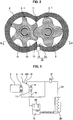
- FIG. 3 is a schematic diagram of a supply path for fluid supplied to the screw compressor 100.
- the supply path for fluid is composed of the screw compressor 100, a centrifuge 19, a cooler 20, auxiliary devices 21 such as a filter and a check valve, and piping 22 connecting them, as shown in FIG. 3 .
- the fluid injected from outside into the screw compressor 100 is mixed in the compressed gas delivered from the screw compressor 100.
- the fluid mixed in the compressed gas is separated from the compressed gas by the centrifuge 19, cooled by the cooler 20, then branched via the auxiliary devices 21 and supplied again to the respective parts.
- the branched fluid is delivered through the fluid supply hole 16 to the compression chamber 13 in the screw compressor 100, through the suction bearing fluid supply hole 17 to the shaft sealing member 7 and the suction bearing 5, and through the delivery bearing fluid supply hole 18 to the delivery bearing 6.
- the branch points of the supply path for fluid are not limited to those provided outside the screw compressor 100 as shown in FIG. 3 , and also include those provided inside the casing 4 of the screw compressor 100.
- the present embodiment of the screw compressor 100 as described above is made to spray fluid supplied into the compression chamber 13 from the outside of the screw compressor 100 over a wide range in the compression chamber 13, to improve effect of cooling the compressed gas, and the like.
- the screw compressor 100 is a screw air compressor to compress air, and fluid supplied from outside into the compression chamber 13 is lubricating oil.
- an object to be compressed is air and lubricating oil is supplied into the compression chamber 13.
- a jet impingement nozzle 23 is provided in the vicinity of a communication portion between the fluid supply hole 16 and the compression chamber 13.
- the jet impingement nozzle 23 is provided such as by press-fitting, screwing, or processing after integral molding.
- the fluid supply hole 16 and the jet impingement nozzle 23 compose the fluid supply portion 38 to supply fluid into the compression chamber 13.
- FIG. 4 is an enlarged cross-sectional view of the jet impingement nozzle 23 in FIG.2 .
- the jet impingement nozzle 23 of the fluid supply portion 38 has a bottomed hole 16a having a bottom 41 which is axially closer to the compression chamber 13 (see FIG. 2 ).
- the jet impingement nozzle 23 includes a first fluid injection hole 24 and a second fluid injection hole 25, with respective axes thereof being inclined at an angle of ⁇ to each other in the same plane to intersect in the compression chamber 13.
- the first fluid injection hole 24 and the second fluid injection hole 25 each have a smaller hole diameter than the fluid supply hole 16 and are formed in an end of the bottomed hole 16a, which is axially closer to the compression chamber 13, that is, in the bottom 41, to communicate with the compression chamber 13 (see FIG. 2 ).
- the lubricating oil flows through the fluid supply hole 16 via the bottomed hole 16a into the first fluid injection hole 24 and the second fluid injection hole 25.
- the lubricating oil injected through each of the first fluid injection hole 24 and the second fluid injection hole 25 collides with each other, and then is spread in a membrane form over a surface S (surface along the depth direction of the plane of paper in FIG. 4 ) which is a plane of symmetry between the first fluid injection hole 24 and the second fluid injection hole 25.
- the oil membrane gradually becomes thinner as it spreads in the width direction along with advancement, and then is broken, splitted, and atomized.
- FIG. 5 is a bore development view having the male bore 9 and the female bore 10 developed on a plane centered by the compression cusp 12.
- FIG. 5 shows male lobe ridges 26, which are lobe ridges of the male rotor 2 (see FIG. 2 ), and female lobe ridges 27, which are lobe ridges of the female rotor 3 (see FIG. 2 ), at a certain moment.
- the male lobe ridges 26 and the female lobe ridges 27 move in parallel from a suction end surface 28 to a delivery end surface 29, along with the rotation of the male rotor 2 and the female rotor 3.
- blow hole 30 Similar to the male lobe ridge 26 and the female lobe ridge 27, the blow hole 30 also repeats a cycle of appearing on the suction end surface 28, and then moving toward the delivery end surface 29 and disappearing at the delivery end surface 29, along with the rotation of the male rotor 2 and the female rotor 3 (see FIG. 2 ).
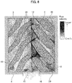
- FIG. 6 is a chart illustrating a fluid analysis result on the flow velocity distribution of the compressed air in the cross-sectional view taken along a line B-B in FIG. 2 .
- FIG. 6 also shows the position of the fluid supply hole 16 provided in the male bore 9.
- external shapes of the cross-sections of the male rotor 2 and the female rotor 3 are clearly indicated by solid lines for easy understanding.
- a trajectory made by the first intersection of an extension line 31 of the female lobe ridge 27 and the male lobe ridge 26 being moved, along with the rotation of the male rotor 2 and the female rotor 3, is defined as a trajectory line 32.
- the first intersection is a point where the female lobe ridge 27, when extending toward the male rotor 2, intersects at the first time with the male lobe ridge 26.
- the communication portion between the fluid supply hole 16 and the male bore 9, where the jet impingement nozzle 23 is provided, that is, the opening of the fluid supply portion 38 (see FIG. 2 ) in the compression chamber 13 is positioned between the compression cusp 12 and the trajectory line 32.
- the jet impingement nozzle 23 is set in FIG. 5 such that a straight line connecting the first fluid injection hole 24 and the second fluid injection hole 25 is parallel to the female lobe ridge 27.
- the screw compressor 100 according to the present embodiment is basically configured as described above. Next, advantageous effects of the screw compressor 100 is described.
- the screw compressor 100 includes the screw rotor 1, the casing 4, and the fluid supply portion 38 to supply fluid in a membrane form into the compression chamber 13 defined in the casing 4, as shown in FIG. 2 .
- the screw rotor 1 has the male rotor 2 and the female rotor 3.
- the casing 4 is formed on the inner surface thereof with the male bore 9 to cover the male rotor 2 and the female bore 10 to cover the female rotor 3.
- the higher pressure intersection line of the male bore 9 and the female bore 10 is defined as the compression cusp 12.
- the trajectory line 32 the trajectory made by the first intersection of the extension line 31 of the female lobe ridge 27 and the male lobe ridge 26 being moved, along with the rotation of the male rotor 2 and the female rotor 3 (see FIG. 2 , the same is applied hereinafter), is defined as the trajectory line 32.
- the opening of the fluid supply portion 38 in the compression chamber 13 is positioned between the compression cusp 12 and the trajectory line 32.
- the fluid supply portion 38 is positioned closer to the compression cusp 12 than the trajectory line 32. This allows for preventing the compressed air leaked through the blow hole 30 from colliding with the male rotor 2 before interfering with the oil membrane flowing out through the fluid supply portion 38. In contrast, if the fluid supply portion 38 is positioned on the compression cusp 12, the effect of promoting atomization of the lubricating oil through interference with the compressed air is small because the leaking compressed air is not accelerated.
- the fluid supplied to the compression chamber 13 from the outside of the screw compressor 100 (see FIG. 1 ) via the fluid supply portion 38 is sufficiently atomized in a shorter distance from the fluid supply portion 38, as described above.
- the particle diameter of the lubricating oil is reduced, so that the heat transfer area between the compressed air and the lubricating oil is increased to promote the cooling effect of air in the compression process.
- the reduced particle diameter of the lubricating oil causes a particle of the lubricating oil to have reduced mass and therefore to be easily affected by the flow of the compressed air.
- the lubricating oil atomized by the compressed air flowing at a high velocity is then spread over a wider range. This makes heat exchanged between the compressed air and the lubricating oil in a wider range.
- the lubricating oil seals the internal clearance of the compression chamber 13 over a wider range, to suppress internal leaks of the compressed gas. As a result, power of the screw compressor 100 is reduced to achieve energy saving.
- the fluid supply portion 38 includes the fluid injection holes 24 and 25, with respective axes thereof being inclined to each other in the same plane to intersect in the compression chamber 13, as shown in FIG. 4 .
- the fluid injected from the respective fluid injection holes 24 and 25 collides with each other, and then spreads in a membrane form over the plane S which is a plane of symmetry between the fluid injection holes 24 and 25. Therefore, the fluid supply portion 38 uses a compact configuration to supply fluid in a membrane form into the compression chamber 13.
- the jet impingement nozzle 23 of the fluid supply portion 38 is attached in FIG. 5 such that a straight line connecting the first fluid injection hole 24 with the second fluid injection hole 25 is parallel to the female lobe ridge 27.
- the oil membrane flowing out of the jet impingement nozzle 23 spreads over the plane S (see FIG. 4 ) orthogonal to the extension line 31.
- the compressed air leaking through the blow holes 30 flows along the female lobe ridge 27, and thus the leaked compressed air collides with the oil membrane orthogonally to the width direction of the latter. Therefore, the velocity difference and interference area between the oil membrane and the compressed air are both peaked, to promote the fluid membrane being further broken and split.
- the width direction of the fluid in a membrane form supplied from the fluid supply portion 38 being spread may be set to any direction between the axial direction of the male rotor 2 and the direction along the male lobe ridge 26. Even with such a configuration, the velocity difference and interference area between the oil membrane and the compressed air are both increased, to promote the fluid membrane being broken and split.
- FIG. 7 is a cross-sectional view of the screw rotor 1 and the vicinity of a fluid supply portion 38a, according to the second embodiment.
- FIG. 8 is a bore development view having the male bore 9 and the female bore 10, according to the second embodiment, developed on a plane centered by the compression cusp 12.
- the second embodiment differs from the first embodiment in FIG. 2 on the point that a lubricating oil supply passage 33 and a compressed air supply portion 34 are each connected upstream of the fluid supply hole 16, as shown in FIG. 7 .
- the fluid supply hole 16, the lubricating oil supply passage 33, and the compressed air supply portion 34 constitute the fluid supply portion 38a according to the second embodiment.
- the lubricating oil flowing into the fluid supply hole 16 through the lubricating oil supply passage 33 is mixed with the compressed air flowing from the compressed air supply portion 34, and then atomized, as shown in FIGS. 7 and 8 . That is, the fluid supply portion 38a causes the lubricating oil to be atomized before being supplied into the compression chamber 13 defined in the casing 4. The atomized lubricating oil then interferes with the compressed air leaking through the blow hole 30, when flowing into the compression chamber 13 from the fluid supply hole 16, to further promote atomization of the lubricating oil so that the particle diameter thereof is reduced.
- the particle diameter of the lubricating oil being reduced has the same advantageous effects as those of the first embodiment. That is, the cooling effect of the compressed air is promoted, the lubricating oil is spread over a wider range to have heat exchange in a wider range, and the internal clearance is sealed over a wider area, to achieve energy saving of the screw compressor 100.
- fluid is supplied from the fluid supply portion 38a in such an inclined direction that the forefront comes closer to the female rotor 3 than a starting end of the supplied fluid, as shown in FIG. 7 . That is, a center axis 35 of the fluid supply hole 16 is inclined toward the female rotor 3. For this reason, the direction of the compressed air being leaked through the blow holes 30 and the direction of the lubricating oil being injected through the fluid supply hole 16 are in a more countercurrent relationship with each other. This increases the velocity difference between the lubricating oil flowing out of the fluid supply portion 38a and the compressed air leaking through the blow holes 30, to further promote atomization of the lubricating oil. Note that fluid may be supplied from the fluid supply portion 38 in such an inclined direction that the forefront comes closer to the female rotor 3 than a starting end of the supplied fluid, also in the first embodiment as described above.
- FIG. 9 is a cross-sectional view of the screw rotor 1 and the vicinity of a fluid supply portion 38b, according to the third embodiment.
- FIG. 10 is a bore development view having the male bore 9 and the female bore 10, according to the third embodiment, developed on a plane centered by the compression cusp 12.
- the third embodiment is different from the first embodiment in FIG. 2 on the point that the casing 4 is divided into a male casing 4a and a female casing 4b by a plane containing the suction cusp 11 and the compression cusp 12.
- a division surface 36 of the male casing 4a, which contains the compression cusp 12, is provided with a recess 37, as shown in FIGS. 9 and 10 .
- the male casing 4a and the female casing 4b coming in contact on the division surface 36 with each other causes the recess 37 to define the fluid supply portion 38b as a slit-shaped passage. That is, the fluid supply portion 38b is formed of a passage surrounded by the inner surface of the recess 37 and the division surface 36 of the female casing 4b.
- the lubricating oil in a membrane form then interferes with the compressed air leaking through the blow holes 30, is broken and split, and is atomized.
- an oil membrane is formed over a wide range from the suction end surface 28 to the delivery end surface 29. Then, the oil membrane is made to interfere with the compressed air leaking through the blow holes 30, to supply the atomized lubricating oil into the entire compression chamber 13.
- the present invention has been described based on the embodiments, but the present invention is not limited thereto and includes various modifications.
- the embodiments have been described in detail for the purpose of illustrating the present invention, and the present invention is not necessarily limited to those having all the configurations described above.
- the configurations of the embodiments may partly be deleted, or added or replaced with another configuration.
- the fluid supplied from the outside of the screw compressor 100 into the compression chamber 13 is lubricating oil, but is not limited thereto and fluid such as water or coolant may be used.
- air is described as an example of an object to be compressed, but another gas such as nitrogen may be used.
Landscapes
- Engineering & Computer Science (AREA)
- Mechanical Engineering (AREA)
- General Engineering & Computer Science (AREA)
- Applications Or Details Of Rotary Compressors (AREA)
Applications Claiming Priority (2)
| Application Number | Priority Date | Filing Date | Title |
|---|---|---|---|
| JP2017169138A JP6899288B2 (ja) | 2017-09-04 | 2017-09-04 | スクリュー圧縮機 |
| PCT/JP2018/029337 WO2019044390A1 (ja) | 2017-09-04 | 2018-08-06 | スクリュー圧縮機 |
Publications (2)
| Publication Number | Publication Date |
|---|---|
| EP3680485A1 true EP3680485A1 (de) | 2020-07-15 |
| EP3680485A4 EP3680485A4 (de) | 2020-12-23 |
Family
ID=65525476
Family Applications (1)
| Application Number | Title | Priority Date | Filing Date |
|---|---|---|---|
| EP18851421.0A Pending EP3680485A4 (de) | 2017-09-04 | 2018-08-06 | Schraubenverdichter |
Country Status (6)
| Country | Link |
|---|---|
| US (1) | US11231036B2 (de) |
| EP (1) | EP3680485A4 (de) |
| JP (1) | JP6899288B2 (de) |
| CN (1) | CN111094750B (de) |
| TW (1) | TWI675149B (de) |
| WO (1) | WO2019044390A1 (de) |
Families Citing this family (4)
| Publication number | Priority date | Publication date | Assignee | Title |
|---|---|---|---|---|
| JP7366799B2 (ja) * | 2020-02-25 | 2023-10-23 | 株式会社日立産機システム | 給液式スクリュー圧縮機 |
| JP7405728B2 (ja) * | 2020-10-29 | 2023-12-26 | 株式会社日立製作所 | スクリュー圧縮室内噴霧装置 |
| CN114320910B (zh) * | 2020-12-02 | 2023-05-19 | 珠海格力电器股份有限公司 | 螺杆压缩机和空调系统 |
| JP2022166884A (ja) * | 2021-04-22 | 2022-11-04 | 株式会社日立産機システム | スクリュー圧縮機 |
Family Cites Families (19)
| Publication number | Priority date | Publication date | Assignee | Title |
|---|---|---|---|---|
| US3138320A (en) * | 1959-01-15 | 1964-06-23 | Svenska Roytor Maskiner Aktieb | Fluid seal for compressor |
| JPS4519671B1 (de) * | 1960-01-16 | 1970-07-04 | ||
| DE2240018C3 (de) | 1971-12-01 | 1979-01-25 | Airfina Ets., Vaduz | Ein- oder mehrstufiger Flügelzellen- oder Schraubenkolbenverdichter |
| JPS52135407A (en) | 1976-05-06 | 1977-11-12 | Hitachi Ltd | Oil cooled rotary compressor |
| JPS588288A (ja) | 1981-07-08 | 1983-01-18 | Hokuetsu Kogyo Co Ltd | スクリュ−圧縮機 |
| NL8900694A (nl) * | 1989-03-21 | 1990-10-16 | Grass Air Holding Bv | Schroefcompressor en werkwijze voor het bedrijven daarvan. |
| US5653585A (en) * | 1993-01-11 | 1997-08-05 | Fresco; Anthony N. | Apparatus and methods for cooling and sealing rotary helical screw compressors |
| JP2001153073A (ja) * | 1999-11-24 | 2001-06-05 | Hitachi Ltd | 給油式スクリュー圧縮機 |
| BE1013944A3 (nl) * | 2001-03-06 | 2003-01-14 | Atlas Copco Airpower Nv | Watergeinjecteerde schroefcompressor. |
| JP3801041B2 (ja) | 2001-12-12 | 2006-07-26 | 株式会社日立製作所 | 水噴射式スクリュー圧縮機 |
| JP4140488B2 (ja) * | 2003-09-09 | 2008-08-27 | ダイキン工業株式会社 | スクリュー圧縮機および冷凍装置 |
| JP4519671B2 (ja) * | 2005-02-09 | 2010-08-04 | 北越紀州製紙株式会社 | 感熱記録体 |
| JP4741992B2 (ja) * | 2006-07-19 | 2011-08-10 | 株式会社日立産機システム | オイルフリースクリュー圧縮機 |
| US9151292B2 (en) * | 2011-01-05 | 2015-10-06 | Hi-Bar Blowers, Inc. | Screw compressor with a shunt pulsation trap |
| BE1020312A3 (nl) * | 2012-02-28 | 2013-07-02 | Atlas Copco Airpower Nv | Compressorinrichting, evenals gebruik van zulke opstelling. |
| JP6126512B2 (ja) | 2013-10-15 | 2017-05-10 | 株式会社神戸製鋼所 | 圧縮機 |
| DE102014105882A1 (de) | 2014-04-25 | 2015-11-12 | Kaeser Kompressoren Se | Rotorpaar für einen Verdichterblock einer Schraubenmaschine |
| CN204226200U (zh) * | 2014-10-31 | 2015-03-25 | 烟台荏原空调设备有限公司 | 一种螺杆式制冷系统及其喷油螺杆式压缩机 |
| JP6606392B2 (ja) | 2015-09-30 | 2019-11-13 | 北越工業株式会社 | 油冷式スクリュ圧縮機 |
-
2017
- 2017-09-04 JP JP2017169138A patent/JP6899288B2/ja active Active
-
2018
- 2018-08-06 WO PCT/JP2018/029337 patent/WO2019044390A1/ja unknown
- 2018-08-06 US US16/644,052 patent/US11231036B2/en active Active
- 2018-08-06 EP EP18851421.0A patent/EP3680485A4/de active Pending
- 2018-08-06 CN CN201880056782.7A patent/CN111094750B/zh active Active
- 2018-08-31 TW TW107130559A patent/TWI675149B/zh active
Also Published As
| Publication number | Publication date |
|---|---|
| US20200386229A1 (en) | 2020-12-10 |
| EP3680485A4 (de) | 2020-12-23 |
| TW201912941A (zh) | 2019-04-01 |
| CN111094750A (zh) | 2020-05-01 |
| CN111094750B (zh) | 2022-04-15 |
| JP6899288B2 (ja) | 2021-07-07 |
| US11231036B2 (en) | 2022-01-25 |
| JP2019044698A (ja) | 2019-03-22 |
| TWI675149B (zh) | 2019-10-21 |
| WO2019044390A1 (ja) | 2019-03-07 |
Similar Documents
| Publication | Publication Date | Title |
|---|---|---|
| US11231036B2 (en) | Screw compressor having an opening of a fluid supply portion between the compression intersection line and a trajectory line | |
| EP3505763B1 (de) | Strömungsmaschine | |
| KR20070100795A (ko) | 베인 펌프 | |
| US10851784B2 (en) | Oil-free screw compressor | |
| JP7350876B2 (ja) | 圧縮機本体及び圧縮機 | |
| TWI719367B (zh) | 螺旋壓縮機 | |
| US11933300B2 (en) | Screw compressor having a screw rotor whose pitch changes in an axial direction from a suction end surface toward a discharge end surface | |
| CN111936745B (zh) | 供液式螺杆压缩机 | |
| US20240183357A1 (en) | Screw compressor | |
| JPH1122665A (ja) | 密閉型電動スクロール圧縮機 | |
| JP7000522B2 (ja) | 給液機構を備えるスクリュー圧縮機 | |
| US20230070782A1 (en) | Liquid Supply Type Screw Compressor | |
| WO2023243171A1 (ja) | スクリュー圧縮機 | |
| WO2019239703A1 (ja) | 液冷式ガス圧縮機 |
Legal Events
| Date | Code | Title | Description |
|---|---|---|---|
| STAA | Information on the status of an ep patent application or granted ep patent |
Free format text: STATUS: THE INTERNATIONAL PUBLICATION HAS BEEN MADE |
|
| PUAI | Public reference made under article 153(3) epc to a published international application that has entered the european phase |
Free format text: ORIGINAL CODE: 0009012 |
|
| STAA | Information on the status of an ep patent application or granted ep patent |
Free format text: STATUS: REQUEST FOR EXAMINATION WAS MADE |
|
| 17P | Request for examination filed |
Effective date: 20200406 |
|
| AK | Designated contracting states |
Kind code of ref document: A1 Designated state(s): AL AT BE BG CH CY CZ DE DK EE ES FI FR GB GR HR HU IE IS IT LI LT LU LV MC MK MT NL NO PL PT RO RS SE SI SK SM TR |
|
| AX | Request for extension of the european patent |
Extension state: BA ME |
|
| DAV | Request for validation of the european patent (deleted) | ||
| DAX | Request for extension of the european patent (deleted) | ||
| A4 | Supplementary search report drawn up and despatched |
Effective date: 20201125 |
|
| RIC1 | Information provided on ipc code assigned before grant |
Ipc: F04C 29/00 20060101ALI20201119BHEP Ipc: F04C 18/16 20060101AFI20201119BHEP Ipc: F04C 29/02 20060101ALI20201119BHEP Ipc: F04C 29/04 20060101ALI20201119BHEP |
|
| TPAC | Observations filed by third parties |
Free format text: ORIGINAL CODE: EPIDOSNTIPA |
|
| STAA | Information on the status of an ep patent application or granted ep patent |
Free format text: STATUS: EXAMINATION IS IN PROGRESS |
|
| 17Q | First examination report despatched |
Effective date: 20230517 |