EP3680402B1 - Einbaukastenanordnung - Google Patents
Einbaukastenanordnung Download PDFInfo
- Publication number
- EP3680402B1 EP3680402B1 EP19151436.3A EP19151436A EP3680402B1 EP 3680402 B1 EP3680402 B1 EP 3680402B1 EP 19151436 A EP19151436 A EP 19151436A EP 3680402 B1 EP3680402 B1 EP 3680402B1
- Authority
- EP
- European Patent Office
- Prior art keywords
- mounting box
- frame
- wall section
- lateral
- frame leg
- Prior art date
- Legal status (The legal status is an assumption and is not a legal conclusion. Google has not performed a legal analysis and makes no representation as to the accuracy of the status listed.)
- Active
Links
Images

Classifications
-
- E—FIXED CONSTRUCTIONS
- E03—WATER SUPPLY; SEWERAGE
- E03C—DOMESTIC PLUMBING INSTALLATIONS FOR FRESH WATER OR WASTE WATER; SINKS
- E03C1/00—Domestic plumbing installations for fresh water or waste water; Sinks
-
- E—FIXED CONSTRUCTIONS
- E03—WATER SUPPLY; SEWERAGE
- E03C—DOMESTIC PLUMBING INSTALLATIONS FOR FRESH WATER OR WASTE WATER; SINKS
- E03C1/00—Domestic plumbing installations for fresh water or waste water; Sinks
- E03C1/02—Plumbing installations for fresh water
- E03C1/021—Devices for positioning or connecting of water supply lines
-
- E—FIXED CONSTRUCTIONS
- E03—WATER SUPPLY; SEWERAGE
- E03C—DOMESTIC PLUMBING INSTALLATIONS FOR FRESH WATER OR WASTE WATER; SINKS
- E03C1/00—Domestic plumbing installations for fresh water or waste water; Sinks
- E03C1/02—Plumbing installations for fresh water
- E03C1/10—Devices for preventing contamination of drinking-water pipes, e.g. means for aerating self-closing flushing valves
-
- E—FIXED CONSTRUCTIONS
- E03—WATER SUPPLY; SEWERAGE
- E03D—WATER-CLOSETS OR URINALS WITH FLUSHING DEVICES; FLUSHING VALVES THEREFOR
- E03D11/00—Other component parts of water-closets, e.g. noise-reducing means in the flushing system, flushing pipes mounted in the bowl, seals for the bowl outlet, devices preventing overflow of the bowl contents; devices forming a water seal in the bowl after flushing, devices eliminating obstructions in the bowl outlet or preventing backflow of water and excrements from the waterpipe
- E03D11/13—Parts or details of bowls; Special adaptations of pipe joints or couplings for use with bowls, e.g. provisions in bowl construction preventing backflow of waste-water from the bowl in the flushing pipe or cistern, provisions for a secondary flushing, for noise-reducing
- E03D11/14—Means for connecting the bowl to the wall, e.g. to a wall outlet
- E03D11/143—Mounting frames for toilets and urinals
-
- E—FIXED CONSTRUCTIONS
- E03—WATER SUPPLY; SEWERAGE
- E03B—INSTALLATIONS OR METHODS FOR OBTAINING, COLLECTING, OR DISTRIBUTING WATER
- E03B1/00—Methods or layout of installations for water supply
- E03B1/04—Methods or layout of installations for water supply for domestic or like local supply
- E03B1/041—Greywater supply systems
-
- E—FIXED CONSTRUCTIONS
- E03—WATER SUPPLY; SEWERAGE
- E03D—WATER-CLOSETS OR URINALS WITH FLUSHING DEVICES; FLUSHING VALVES THEREFOR
- E03D5/00—Special constructions of flushing devices, e.g. closed flushing system
- E03D5/003—Grey water flushing systems
- E03D5/006—Constructional details of cisterns for using greywater
Definitions
- the present invention relates to an installation box arrangement for accommodating sanitary fittings according to the preamble of claim 1.
- the installation box has a bottom box and a front component.
- the position of the front component can be shifted relative to the bottom box, such that a front edge of the front component can be adjusted to an installation situation.
- the object of the present invention is to specify an installation box that overcomes the disadvantages of the prior art.
- any leakage water should be able to be drained well out of the installation box.
- an installation box arrangement for sanitary fittings comprises an installation box for fixed connection to a stationary mounting structure, such as a mounting frame, which installation box has a side wall defining an interior space with a lower wall section and adjoining the lower wall section at the top having lateral wall sections, and an adjustment frame with a frame wall.
- the setting frame is slidably mounted on the installation box between two end positions, such that the position of the front edges of the frame wall can be adjusted to the installation situation. Once the setting has been made, the setting frame can be fixed to the installation box. This means that the adjustment frame is firmly connected to the installation box.
- the interior space serves to accommodate said sanitary fittings.
- the setting frame lies with a lower frame piece on the outside of the lower wall section of the side wall of the installation box with respect to the interior space, with the lower frame piece extending under the lower wall section of the side wall in every position.
- the arrangement of the lower side wall which is on the outside of the interior and below the lower wall section, has the advantage that any leakage water coming from the sanitary fittings can drip from the lower wall section onto the lower frame piece. As a result, leakage water can easily be caught by the lower frame piece.
- the setting frame can fulfill two different functions at the same time; on the one hand, the installation box arrangement can be adapted to the local situation on site with the setting frame and, on the other hand, the setting frame serves to channel away any water leakage.
- the installation box and the assembly structure are preferably located behind a pre-wall, with the adjustable setting frame being able to compensate for any installation tolerances between the installation box and the pre-wall.
- the front edges are aligned parallel to the level of the pre-wall.
- the setting frame and the installation box are designed to be substantially rectangular in cross section, seen from the front.
- the sanitary fitting can be, for example, a drain valve, a siphon, a fresh water connection and/or other sanitary elements.
- sanitary fittings can be arranged in the interior.
- electrical devices are also arranged in the interior in addition to the sanitary fittings.
- the lower frame piece In the installed position, the lower frame piece is preferably inclined at an angle at least in sections relative to a horizontal plane, such that any leakage water flowing from the interior onto the frame piece is guided away from the installation box.
- the lower frame piece In the installed position, the lower frame piece is preferably inclined at an angle at least in sections relative to the inner surface of the lower wall section, such that any leakage water flowing from the interior onto the frame piece is guided away from the installation box.
- the inner surface is preferably horizontal.
- the angle is preferably in a range from 1° to 10°.
- any leakage water can easily flow away from the installation box in the direction of the front edges. This means that leakage water is guided out of the installation situation in the direction of the pre-wall, in particular in front of the pre-wall.
- the installation box arrangement according to the invention also has at least one water outlet point, with the lower frame piece being arranged below the at least one water outlet point, such that any water that has leaked from the at least one water outlet point can flow off onto the lower frame piece.
- the lower frame leg extends under the water outlet point and catches the leakage water accordingly.
- the arrangement of at least one specific water outlet point has the advantage that the leakage water can be transferred at the specific location from the installation box to the lower frame piece of the setting frame.
- This has the advantage that the frame piece essentially only has to extend under the lateral wall section of the installation box at the point at which a water outlet point is also provided.
- the lower frame leg can be optimized with regard to other aspects.
- the water outlet point from a front edge of the installation box are formed.
- the at least one water outlet point breaks through a reinforcement flap of the lower wall section.
- Two water outlet points are particularly preferably arranged in the area in which the lateral wall sections adjoin the lower wall section.
- more than two water outlet points can also be arranged.
- the lower wall section of the installation box arrangement according to the invention has a reinforcing shackle protruding essentially at right angles from the lower wall section, the reinforcing shackle being broken through by the at least one water outlet point and/or the water outlet point being arranged at the end of the reinforcing shackle.
- the reinforcement flap serves as a mechanical reinforcement element for the lower wall section.
- the reinforcement flap is preferably arranged in such a way that it extends into the interior space.
- the reinforcing tab also serves as a retaining element or guide element for the leakage water.
- the lower frame piece preferably has a lateral frame piece that protrudes upwards, which lateral frame piece lies in sections outside the interior space and in sections inside the interior space.
- the lateral frame members located within the interior preferably rest against the lateral wall sections of the installation box.
- the frame legs located outside of the interior preferably extend from below around the interface between the lower wall section and the side wall section of the installation box around.
- the lateral frame members preferably have a slot which is open towards the installation box and which slot accommodates parts of the lateral wall section of the installation box.
- the lateral wall sections preferably have a bent section running parallel to the lower wall section, the bent section extending transversely through the slot.
- the setting frame is preferably made in several parts, with the lateral frame members being at least partially made of plastic and the lower frame member being made of metal, with the lateral frame members being connected to the lower frame members.
- the installation box can be manufactured very easily.
- An upper frame piece of the adjustment frame is preferably made of metal and is connected to the side frame pieces.
- the side frame legs of the adjustment frame preferably have at least one slot, with a screw being guided through the slot and engaging in threaded openings on the side wall section of the installation box; and the ends of the slot defining said end positions.
- the at least one slot is oriented in the direction of the adjustment movement.
- two slots are arranged spaced apart from one another and running parallel to one another for each frame piece.
- the installation box preferably has a rear wall which extends over the entire cross section.
- the adjustment frame and/or the installation box preferably has fastening points for fastening hinges of a service door.
- the lower wall section of the installation box and the lower frame piece of the setting frame each have at least one through-opening for a drain pipe to pass through.
- the passage openings lie in the middle in the lower wall section or in the lower frame piece.
- the passage opening in the lower frame piece is preferably in the form of a slot.
- the passage opening in the lower wall section is preferably circular.
- the through-opening in the lower wall section is provided with a seal which correspondingly seals the gap between the through-opening and the drain pipe.
- the upper frame limb of the setting frame and the upper wall limb preferably each have at least one through-opening for the passage of fresh water lines and/or waste water lines.
- the passage opening in the upper frame piece is preferably in the form of a slot.
- the passage opening in the upper wall section is preferably circular.
- a partition wall is preferably also arranged in the interior space, which divides the interior space into a fresh water space and a waste water space.
- the partition wall extends through the interior space from the lower wall section to the upper wall section.
- the arrangement of the partition wall prevents waste water from flowing into the fresh water space or fresh water from flowing into the waste water space.
- the arrangement of the partition thus results in the advantage that sanitary fittings for the fresh water supply and sanitary fittings for the drainage of waste water can be arranged in the same installation box.
- the dividing wall preferably extends transversely through the interior space in such a way that the dividing wall is connected with its end regions to the side wall in each case. This means that there are preferably no free ends at the side wall. It is also possible that the partition wall has free ends in the interior.
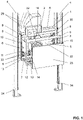
- the installation box arrangement 1 for sanitary fittings 2 is shown.
- the installation box arrangement 1 essentially comprises an installation box 3 and an adjustment frame 9 which is arranged to be displaceable relative to the installation box 3 .
- the installation box 3 is firmly connected to a stationary mounting structure 4 .
- the installation box 3 is connected to two supports 34 of a mounting frame.
- the supports 34 can be connected to a building floor with their feet.
- the mounting box arrangement also includes a blind frame 35, which is used for the optical cladding.
- a service door 23 is arranged.
- the frame 35 is optional and can be fitted with the installation box 3 or the Setting frame 9 are connected.
- the installation box 3 is used for the fixed connection to a stationary mounting structure 4 .
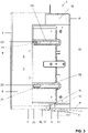
- the installation box 3 has a side wall 6 that defines an interior space 5 .
- the side wall 6 surrounds the inner space 5 laterally.
- a rear wall 22 is also arranged, which essentially completely closes the installation box 3 to the rear.
- To the front of the installation box 3 is open. That is, the side wall 6 defines a front opening 36 through which the interior 5 is accessible.
- the side wall 6 has a lower wall section 7 towards the bottom. Two lateral wall sections 8 of the side wall 6 adjoin the lower wall section 7 at the top. An upper wall section 37 then connects the two lateral wall sections 8.
- the lower wall section 7 is formed parallel to the upper wall section 37 and the two lateral wall sections 8 also run parallel to one another.
- the lateral wall sections 8 are perpendicular to the lower wall section 7 and to the upper wall section 37. Other shapes are also conceivable.
- the setting frame 9 essentially has a frame wall 10 .
- the setting frame 9 is slidably mounted on the installation box 3 between two end positions. The displacement is such that the position of the front edges 11 of the frame wall 10 can be adjusted to the installation situation. This means that the frame wall 10 can be adjusted with its front edges 11 flush with the front side of a pre-wall, which can optionally be covered with fleece. After the setting has been made, the setting frame 9 can be fixed accordingly on the installation box 3, so that the setting frame 9 cannot be moved any further.
- the interior 5 serves to accommodate said sanitary fittings 2 .
- a drain valve 31 located after the drain valve 31 and a fresh water connection 33 are arranged in the interior 5 .
- These components are used to supply fresh water to a washstand or to drain waste water from said washstand.
- the arrangement of other sanitary fittings for other elements is also conceivable.
- the setting frame 9 is arranged with a lower frame leg 12 with respect to the interior 5 on the outside of the lower wall section 7 of the side wall 6 of the installation box 3 .
- the lower frame member 12 extends below the side wall 6.
- the lower frame member 12 is designed in such a way that the lower frame member 12 is in of each position of the adjustment frame 9 under the lower wall section 7 of the side wall 6. In other words, the lower frame piece 12 protrudes in every position under the lower wall section 7 of the side wall 6. This has the advantage that any leakage water coming from said sanitary fittings 2 can flow from the interior via the lower wall section 7 to the lower frame piece 12. The leakage water can then flow off via the lower frame piece 12 .
- the lower frame piece 12 in the installed position is designed to be inclined at an angle in sections with respect to a horizontal plane H.
- the angle bears the reference ⁇ in the figure 3 .
- the angle is such that the leakage water that hits the lower frame piece 12 is conducted away from the installation box 3 .
- the lower frame piece 12 in the installed position, is designed to be inclined at an angle with respect to the inner surface 30 of the lower wall section.
- the angle ⁇ is preferably in a range from 1° to 10°.
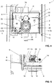
- the installation box 3 has two water outlet points 13 . These two water outlet points 13 are each arranged in the corner area of the installation box 3 . This means that the water outlet points 13 are arranged in an area in which the lateral wall sections 8 connect to the lower wall section 7 . Any leakage water will flow laterally on the lower wall section 7 to the water outlet points 13 and can flow off there onto the lower frame piece 12 . However, it is also possible to arrange further outlet points 13 on the lower wall section 7 between the two lateral wall sections 8 . In the figure 5 the water exit through the outlet points 13 is symbolized by an arrow W.
- the lower wall section 7 of the installation box 3 has a reinforcing tab 14 protruding essentially at right angles from the lower wall section 7 .
- the reinforcing tab 14 is shortened here with respect to the distance between the two lateral wall sections 8 . This creates space for the water outlet point 13 between the end regions of the reinforcing flap 14 and the respective lateral wall section 8 .
- the water outlet point 13 is arranged here at the end of the reinforcement strap 14 .
- the reinforcement flap 14 is broken through by two water outlet points 13 between the two lateral wall sections 8 .
- the reinforcement flap 14 has two effects.
- the reinforcing lug 14 serves to reinforce the mounting box 3.
- the reinforcing lug 14 serves as a guiding element for the leakage water. This means that the reinforcement flap 14 guides the leakage water to the corresponding water outlet points 13.
- the lower frame member 12 has, as in the Figures 2 to 4 shown, each have an upwardly projecting lateral frame piece 15.
- the lateral frame member 15 is here arranged in sections outside the interior 5 and extends here in sections within the interior 5 .
- the slot 16 accommodates parts of the side wall section 8 of the installation box 3 .
- This recording can be found in the figure 2 be recognized well.
- FIG 5 which is a detail of figure 4 shows, it is shown that in the area of the transition from the lower wall section 7 to the side wall section 8 of the installation box 3, a bent section 17 is arranged.
- the bent section 17 runs parallel to the lower wall section 7 and essentially at right angles to the side wall section 8 . At this point is the transition at which the lateral frame section 15 changes from its position lying outside the interior space 5 to the position lying inside the interior space 5 .
- the setting frame 9 is designed in several parts.
- the side frame members 15 consist essentially of plastic and the lower frame member 12 is essentially made of metal.
- the lower frame member 12 also provides parts of the lateral frame member 15 here. These parts include said slot 16.
- the adjustment frame 9 also includes an upper frame piece 18 which is also made of metal and is connected to the side frame pieces 15 .
- the upper frame piece 18 extends into the interior 5 of the installation box 3.
- the side frame members 15 of the setting frame 9 have at least one slot 19 .
- two slotted holes 19 running parallel to one another and spaced apart are arranged per frame piece 15 .
- one screw 20 extends through the slot 19 and engages in threaded openings 21 on the lateral wall section 8 of the installation box 3 .
- the setting frame 9 can be moved relative to the installation box 3 .
- the screws 20 are tightened, the setting frame 9 is fixed accordingly on the installation box 3 .
- the ends of the slot 19 essentially define said end positions. This means that the mounting box 3 can be displaced relative to the mounting box 3 by the length of the elongated hole 19 .
- both the lower wall section 7 of the installation box and the lower frame piece 12 of the setting frame 9 each have at least one through-opening 24, 25 for a drain pipe 26 to pass through.
- the through-opening 24 in the lower wall section 7 is provided with a seal 38 so that no leakage water can escape between the drain pipe 26 and the through-opening 24 .
- the through-opening 25 in the lower frame piece 12 of the setting frame 9 is designed as a slot so that the displaceability of the setting frame 9 is ensured when the drain pipe 26 is already installed.
- At least one through opening 27 , 28 is also arranged in the upper frame piece 18 and in the upper wall section 37 .
- Fresh water lines 29 or the drain pipe can be guided into the interior 5 through these passage openings 27 , 28 .
- the through hole 28 in the upper wall section 37 of the setting frame 9 is also designed as a slot, so that the mobility of the setting frame 9 is guaranteed here.
- a partition 39 which divides the interior space into a fresh water space 40 and a waste water space 41 .
- the partition extends here across the interior 5 from the lower wall section 7 to the upper wall section 37 .
- REFERENCE CHARACTER LIST 1 built-in box arrangement 27 passage opening 2 sanitary fittings 28 passage opening 3 installation box 29 fresh water line 4 assembly structure 30 Inner surface 5 inner space 31 drain valve 6 Side wall 32 siphon 7 lower wall section 33 fresh water connection 8th lateral wall section 34 Support 9 adjustment frame 35 frame 10 frame wall 36 front opening 11 front edges 37 upper wall section 12 lower frame leg 38 poetry 13 water outlet point 39 partition wall 14 reinforcement tab 40 freshwater room 15 side frame leg 41 sewage room 16 slot a angle 17 cropped section H horizontal plane 18 upper frame leg W water leakage 19 Long hole 20 screw 21 threaded openings 22 back panel 23 service door 24 passage opening 25 passage opening 26 drain pipe
Landscapes
- Health & Medical Sciences (AREA)
- Life Sciences & Earth Sciences (AREA)
- Engineering & Computer Science (AREA)
- Hydrology & Water Resources (AREA)
- Public Health (AREA)
- Water Supply & Treatment (AREA)
- Sanitary Device For Flush Toilet (AREA)
- Residential Or Office Buildings (AREA)
Priority Applications (8)
| Application Number | Priority Date | Filing Date | Title |
|---|---|---|---|
| EP19151436.3A EP3680402B1 (de) | 2019-01-11 | 2019-01-11 | Einbaukastenanordnung |
| PL19151436.3T PL3680402T3 (pl) | 2019-01-11 | 2019-01-11 | Układ puszki do zabudowy |
| AU2019240836A AU2019240836B2 (en) | 2018-03-29 | 2019-03-28 | Drain arrangement for a washstand |
| CN201980023149.2A CN111936708B (zh) | 2018-03-29 | 2019-03-28 | 用于盥洗台的排放装置 |
| EP19714201.1A EP3775415B1 (de) | 2018-03-29 | 2019-03-28 | Ablaufanordnung für einen waschtisch |
| US17/042,597 US11486118B2 (en) | 2018-03-29 | 2019-03-28 | Drain arrangement for a washstand |
| PCT/EP2019/057884 WO2019185810A1 (de) | 2018-03-29 | 2019-03-28 | Ablaufanordnung für einen waschtisch |
| CH01616/19A CH715804B1 (de) | 2019-01-11 | 2019-12-13 | Einbaukastenanordnung für die Aufnahme von Sanitärarmaturen. |
Applications Claiming Priority (1)
| Application Number | Priority Date | Filing Date | Title |
|---|---|---|---|
| EP19151436.3A EP3680402B1 (de) | 2019-01-11 | 2019-01-11 | Einbaukastenanordnung |
Publications (2)
| Publication Number | Publication Date |
|---|---|
| EP3680402A1 EP3680402A1 (de) | 2020-07-15 |
| EP3680402B1 true EP3680402B1 (de) | 2022-08-31 |
Family
ID=65019412
Family Applications (1)
| Application Number | Title | Priority Date | Filing Date |
|---|---|---|---|
| EP19151436.3A Active EP3680402B1 (de) | 2018-03-29 | 2019-01-11 | Einbaukastenanordnung |
Country Status (3)
| Country | Link |
|---|---|
| EP (1) | EP3680402B1 (pl) |
| CH (1) | CH715804B1 (pl) |
| PL (1) | PL3680402T3 (pl) |
Family Cites Families (3)
| Publication number | Priority date | Publication date | Assignee | Title |
|---|---|---|---|---|
| US3493977A (en) * | 1967-06-01 | 1970-02-10 | Edward C Green | Safety bathtub diverter spout |
| DE9410742U1 (de) | 1994-07-08 | 1994-10-27 | Fa. Bader, 89250 Senden | Einbaukasten |
| US7357148B1 (en) * | 2006-02-17 | 2008-04-15 | Michael Gibson | Prefabricated in-wall water service box |
-
2019
- 2019-01-11 PL PL19151436.3T patent/PL3680402T3/pl unknown
- 2019-01-11 EP EP19151436.3A patent/EP3680402B1/de active Active
- 2019-12-13 CH CH01616/19A patent/CH715804B1/de not_active IP Right Cessation
Also Published As
| Publication number | Publication date |
|---|---|
| PL3680402T3 (pl) | 2022-12-19 |
| CH715804B1 (de) | 2020-12-30 |
| EP3680402A1 (de) | 2020-07-15 |
| CH715804A2 (de) | 2020-07-15 |
Similar Documents
| Publication | Publication Date | Title |
|---|---|---|
| EP2045403B1 (de) | Ablaufgarnitur mit integriertem Überlauf | |
| EP3746607B1 (de) | Anordnung umfassend eine anschlussvorrichtung und einen sanitärartikel | |
| EP2357307A2 (de) | Sektionaltor | |
| DE29600610U1 (de) | Duschabtrennung | |
| EP0386559B1 (de) | Duschabtrennung | |
| DE4403653C1 (de) | Duschabtrennung | |
| EP3680402B1 (de) | Einbaukastenanordnung | |
| EP3775415B1 (de) | Ablaufanordnung für einen waschtisch | |
| DE102007048329B3 (de) | Entwässerungsrinne | |
| DE19533179C2 (de) | Vorrichtung für den Einbau einer Bade- oder Duschwanne | |
| DE102013102379A1 (de) | Ablaufanordnung | |
| DE202008015581U1 (de) | Bauelement für Fensteröffnungen | |
| DE102022131506A1 (de) | Mobiles Hochwasserschutzsystem | |
| DE10204683B4 (de) | Becken | |
| DE102007010774B4 (de) | Anordnung mit einem vertikalen zylindrischen Ablaufrohr | |
| EP3680405B1 (de) | Einbaukasten | |
| DE202010008840U1 (de) | Duschrinnenanordnung mit Klappenbefestigung | |
| EP2818600B1 (de) | Bodeneinlauf mit justierbarer Blende | |
| EP4063576B1 (de) | Waschtischanordnung | |
| DE102013101208B4 (de) | Ablaufvorrichtung zur Anordnung in einem Boden angrenzend an eine Wand | |
| DE29602829U1 (de) | Dusch- und Badeanordnung | |
| DE202012001550U1 (de) | Ablauf mit einem Ablaufkörper | |
| DE102016103067B4 (de) | Einbaugehäuse für Sanitärarmaturen | |
| DE19703790A1 (de) | Duschkabine | |
| DE9104764U1 (de) | Wassereindringschutz für Sanitärarmaturen |
Legal Events
| Date | Code | Title | Description |
|---|---|---|---|
| PUAI | Public reference made under article 153(3) epc to a published international application that has entered the european phase |
Free format text: ORIGINAL CODE: 0009012 |
|
| STAA | Information on the status of an ep patent application or granted ep patent |
Free format text: STATUS: THE APPLICATION HAS BEEN PUBLISHED |
|
| AK | Designated contracting states |
Kind code of ref document: A1 Designated state(s): AL AT BE BG CH CY CZ DE DK EE ES FI FR GB GR HR HU IE IS IT LI LT LU LV MC MK MT NL NO PL PT RO RS SE SI SK SM TR |
|
| AX | Request for extension of the european patent |
Extension state: BA ME |
|
| STAA | Information on the status of an ep patent application or granted ep patent |
Free format text: STATUS: REQUEST FOR EXAMINATION WAS MADE |
|
| 17P | Request for examination filed |
Effective date: 20201102 |
|
| RBV | Designated contracting states (corrected) |
Designated state(s): AL AT BE BG CH CY CZ DE DK EE ES FI FR GB GR HR HU IE IS IT LI LT LU LV MC MK MT NL NO PL PT RO RS SE SI SK SM TR |
|
| GRAP | Despatch of communication of intention to grant a patent |
Free format text: ORIGINAL CODE: EPIDOSNIGR1 |
|
| STAA | Information on the status of an ep patent application or granted ep patent |
Free format text: STATUS: GRANT OF PATENT IS INTENDED |
|
| RIC1 | Information provided on ipc code assigned before grant |
Ipc: E03C 1/02 20060101AFI20220217BHEP |
|
| INTG | Intention to grant announced |
Effective date: 20220322 |
|
| GRAS | Grant fee paid |
Free format text: ORIGINAL CODE: EPIDOSNIGR3 |
|
| GRAA | (expected) grant |
Free format text: ORIGINAL CODE: 0009210 |
|
| STAA | Information on the status of an ep patent application or granted ep patent |
Free format text: STATUS: THE PATENT HAS BEEN GRANTED |
|
| AK | Designated contracting states |
Kind code of ref document: B1 Designated state(s): AL AT BE BG CH CY CZ DE DK EE ES FI FR GB GR HR HU IE IS IT LI LT LU LV MC MK MT NL NO PL PT RO RS SE SI SK SM TR |
|
| REG | Reference to a national code |
Ref country code: CH Ref legal event code: EP Ref country code: GB Ref legal event code: FG4D Free format text: NOT ENGLISH |
|
| REG | Reference to a national code |
Ref country code: AT Ref legal event code: REF Ref document number: 1515379 Country of ref document: AT Kind code of ref document: T Effective date: 20220915 Ref country code: DE Ref legal event code: R096 Ref document number: 502019005459 Country of ref document: DE |
|
| REG | Reference to a national code |
Ref country code: IE Ref legal event code: FG4D Free format text: LANGUAGE OF EP DOCUMENT: GERMAN |
|
| REG | Reference to a national code |
Ref country code: LT Ref legal event code: MG9D |
|
| REG | Reference to a national code |
Ref country code: NL Ref legal event code: MP Effective date: 20220831 |
|
| PG25 | Lapsed in a contracting state [announced via postgrant information from national office to epo] |
Ref country code: SE Free format text: LAPSE BECAUSE OF FAILURE TO SUBMIT A TRANSLATION OF THE DESCRIPTION OR TO PAY THE FEE WITHIN THE PRESCRIBED TIME-LIMIT Effective date: 20220831 Ref country code: RS Free format text: LAPSE BECAUSE OF FAILURE TO SUBMIT A TRANSLATION OF THE DESCRIPTION OR TO PAY THE FEE WITHIN THE PRESCRIBED TIME-LIMIT Effective date: 20220831 Ref country code: NO Free format text: LAPSE BECAUSE OF FAILURE TO SUBMIT A TRANSLATION OF THE DESCRIPTION OR TO PAY THE FEE WITHIN THE PRESCRIBED TIME-LIMIT Effective date: 20221130 Ref country code: LV Free format text: LAPSE BECAUSE OF FAILURE TO SUBMIT A TRANSLATION OF THE DESCRIPTION OR TO PAY THE FEE WITHIN THE PRESCRIBED TIME-LIMIT Effective date: 20220831 Ref country code: LT Free format text: LAPSE BECAUSE OF FAILURE TO SUBMIT A TRANSLATION OF THE DESCRIPTION OR TO PAY THE FEE WITHIN THE PRESCRIBED TIME-LIMIT Effective date: 20220831 Ref country code: FI Free format text: LAPSE BECAUSE OF FAILURE TO SUBMIT A TRANSLATION OF THE DESCRIPTION OR TO PAY THE FEE WITHIN THE PRESCRIBED TIME-LIMIT Effective date: 20220831 |
|
| PG25 | Lapsed in a contracting state [announced via postgrant information from national office to epo] |
Ref country code: IS Free format text: LAPSE BECAUSE OF FAILURE TO SUBMIT A TRANSLATION OF THE DESCRIPTION OR TO PAY THE FEE WITHIN THE PRESCRIBED TIME-LIMIT Effective date: 20221231 Ref country code: HR Free format text: LAPSE BECAUSE OF FAILURE TO SUBMIT A TRANSLATION OF THE DESCRIPTION OR TO PAY THE FEE WITHIN THE PRESCRIBED TIME-LIMIT Effective date: 20220831 Ref country code: GR Free format text: LAPSE BECAUSE OF FAILURE TO SUBMIT A TRANSLATION OF THE DESCRIPTION OR TO PAY THE FEE WITHIN THE PRESCRIBED TIME-LIMIT Effective date: 20221201 |
|
| PG25 | Lapsed in a contracting state [announced via postgrant information from national office to epo] |
Ref country code: SM Free format text: LAPSE BECAUSE OF FAILURE TO SUBMIT A TRANSLATION OF THE DESCRIPTION OR TO PAY THE FEE WITHIN THE PRESCRIBED TIME-LIMIT Effective date: 20220831 Ref country code: RO Free format text: LAPSE BECAUSE OF FAILURE TO SUBMIT A TRANSLATION OF THE DESCRIPTION OR TO PAY THE FEE WITHIN THE PRESCRIBED TIME-LIMIT Effective date: 20220831 Ref country code: PT Free format text: LAPSE BECAUSE OF FAILURE TO SUBMIT A TRANSLATION OF THE DESCRIPTION OR TO PAY THE FEE WITHIN THE PRESCRIBED TIME-LIMIT Effective date: 20230102 Ref country code: ES Free format text: LAPSE BECAUSE OF FAILURE TO SUBMIT A TRANSLATION OF THE DESCRIPTION OR TO PAY THE FEE WITHIN THE PRESCRIBED TIME-LIMIT Effective date: 20220831 Ref country code: DK Free format text: LAPSE BECAUSE OF FAILURE TO SUBMIT A TRANSLATION OF THE DESCRIPTION OR TO PAY THE FEE WITHIN THE PRESCRIBED TIME-LIMIT Effective date: 20220831 Ref country code: CZ Free format text: LAPSE BECAUSE OF FAILURE TO SUBMIT A TRANSLATION OF THE DESCRIPTION OR TO PAY THE FEE WITHIN THE PRESCRIBED TIME-LIMIT Effective date: 20220831 |
|
| PG25 | Lapsed in a contracting state [announced via postgrant information from national office to epo] |
Ref country code: SK Free format text: LAPSE BECAUSE OF FAILURE TO SUBMIT A TRANSLATION OF THE DESCRIPTION OR TO PAY THE FEE WITHIN THE PRESCRIBED TIME-LIMIT Effective date: 20220831 Ref country code: EE Free format text: LAPSE BECAUSE OF FAILURE TO SUBMIT A TRANSLATION OF THE DESCRIPTION OR TO PAY THE FEE WITHIN THE PRESCRIBED TIME-LIMIT Effective date: 20220831 |
|
| REG | Reference to a national code |
Ref country code: DE Ref legal event code: R097 Ref document number: 502019005459 Country of ref document: DE |
|
| P01 | Opt-out of the competence of the unified patent court (upc) registered |
Effective date: 20230523 |
|
| PG25 | Lapsed in a contracting state [announced via postgrant information from national office to epo] |
Ref country code: NL Free format text: LAPSE BECAUSE OF FAILURE TO SUBMIT A TRANSLATION OF THE DESCRIPTION OR TO PAY THE FEE WITHIN THE PRESCRIBED TIME-LIMIT Effective date: 20220831 Ref country code: AL Free format text: LAPSE BECAUSE OF FAILURE TO SUBMIT A TRANSLATION OF THE DESCRIPTION OR TO PAY THE FEE WITHIN THE PRESCRIBED TIME-LIMIT Effective date: 20220831 |
|
| PLBE | No opposition filed within time limit |
Free format text: ORIGINAL CODE: 0009261 |
|
| STAA | Information on the status of an ep patent application or granted ep patent |
Free format text: STATUS: NO OPPOSITION FILED WITHIN TIME LIMIT |
|
| 26N | No opposition filed |
Effective date: 20230601 |
|
| PG25 | Lapsed in a contracting state [announced via postgrant information from national office to epo] |
Ref country code: SI Free format text: LAPSE BECAUSE OF FAILURE TO SUBMIT A TRANSLATION OF THE DESCRIPTION OR TO PAY THE FEE WITHIN THE PRESCRIBED TIME-LIMIT Effective date: 20220831 |
|
| GBPC | Gb: european patent ceased through non-payment of renewal fee |
Effective date: 20230111 |
|
| PG25 | Lapsed in a contracting state [announced via postgrant information from national office to epo] |
Ref country code: LU Free format text: LAPSE BECAUSE OF NON-PAYMENT OF DUE FEES Effective date: 20230111 |
|
| REG | Reference to a national code |
Ref country code: BE Ref legal event code: MM Effective date: 20230131 |
|
| PG25 | Lapsed in a contracting state [announced via postgrant information from national office to epo] |
Ref country code: GB Free format text: LAPSE BECAUSE OF NON-PAYMENT OF DUE FEES Effective date: 20230111 |
|
| PG25 | Lapsed in a contracting state [announced via postgrant information from national office to epo] |
Ref country code: BE Free format text: LAPSE BECAUSE OF NON-PAYMENT OF DUE FEES Effective date: 20230131 |
|
| PG25 | Lapsed in a contracting state [announced via postgrant information from national office to epo] |
Ref country code: IE Free format text: LAPSE BECAUSE OF NON-PAYMENT OF DUE FEES Effective date: 20230111 |
|
| PG25 | Lapsed in a contracting state [announced via postgrant information from national office to epo] |
Ref country code: IT Free format text: LAPSE BECAUSE OF FAILURE TO SUBMIT A TRANSLATION OF THE DESCRIPTION OR TO PAY THE FEE WITHIN THE PRESCRIBED TIME-LIMIT Effective date: 20220831 |
|
| PGFP | Annual fee paid to national office [announced via postgrant information from national office to epo] |
Ref country code: PL Payment date: 20231229 Year of fee payment: 6 Ref country code: FR Payment date: 20240122 Year of fee payment: 6 |
|
| PG25 | Lapsed in a contracting state [announced via postgrant information from national office to epo] |
Ref country code: MC Free format text: LAPSE BECAUSE OF FAILURE TO SUBMIT A TRANSLATION OF THE DESCRIPTION OR TO PAY THE FEE WITHIN THE PRESCRIBED TIME-LIMIT Effective date: 20220831 |
|
| PG25 | Lapsed in a contracting state [announced via postgrant information from national office to epo] |
Ref country code: MC Free format text: LAPSE BECAUSE OF FAILURE TO SUBMIT A TRANSLATION OF THE DESCRIPTION OR TO PAY THE FEE WITHIN THE PRESCRIBED TIME-LIMIT Effective date: 20220831 |
|
| PG25 | Lapsed in a contracting state [announced via postgrant information from national office to epo] |
Ref country code: BG Free format text: LAPSE BECAUSE OF FAILURE TO SUBMIT A TRANSLATION OF THE DESCRIPTION OR TO PAY THE FEE WITHIN THE PRESCRIBED TIME-LIMIT Effective date: 20220831 |
|
| PG25 | Lapsed in a contracting state [announced via postgrant information from national office to epo] |
Ref country code: BG Free format text: LAPSE BECAUSE OF FAILURE TO SUBMIT A TRANSLATION OF THE DESCRIPTION OR TO PAY THE FEE WITHIN THE PRESCRIBED TIME-LIMIT Effective date: 20220831 |
|
| REG | Reference to a national code |
Ref country code: AT Ref legal event code: PC Ref document number: 1515379 Country of ref document: AT Kind code of ref document: T Owner name: GEBERIT INTERNATIONAL AG, CH Effective date: 20241118 |
|
| PGFP | Annual fee paid to national office [announced via postgrant information from national office to epo] |
Ref country code: DE Payment date: 20250121 Year of fee payment: 7 |
|
| PGFP | Annual fee paid to national office [announced via postgrant information from national office to epo] |
Ref country code: AT Payment date: 20250122 Year of fee payment: 7 Ref country code: CH Payment date: 20250201 Year of fee payment: 7 |
|
| PG25 | Lapsed in a contracting state [announced via postgrant information from national office to epo] |
Ref country code: CY Free format text: LAPSE BECAUSE OF FAILURE TO SUBMIT A TRANSLATION OF THE DESCRIPTION OR TO PAY THE FEE WITHIN THE PRESCRIBED TIME-LIMIT; INVALID AB INITIO Effective date: 20190111 |
|
| PG25 | Lapsed in a contracting state [announced via postgrant information from national office to epo] |
Ref country code: HU Free format text: LAPSE BECAUSE OF FAILURE TO SUBMIT A TRANSLATION OF THE DESCRIPTION OR TO PAY THE FEE WITHIN THE PRESCRIBED TIME-LIMIT; INVALID AB INITIO Effective date: 20190111 |
|
| PG25 | Lapsed in a contracting state [announced via postgrant information from national office to epo] |
Ref country code: FR Free format text: LAPSE BECAUSE OF NON-PAYMENT OF DUE FEES Effective date: 20250131 |
|
| PG25 | Lapsed in a contracting state [announced via postgrant information from national office to epo] |
Ref country code: TR Free format text: LAPSE BECAUSE OF FAILURE TO SUBMIT A TRANSLATION OF THE DESCRIPTION OR TO PAY THE FEE WITHIN THE PRESCRIBED TIME-LIMIT Effective date: 20220831 |
|
| REG | Reference to a national code |
Ref country code: CH Ref legal event code: U11 Free format text: ST27 STATUS EVENT CODE: U-0-0-U10-U11 (AS PROVIDED BY THE NATIONAL OFFICE) Effective date: 20260201 |