EP3680032A1 - Dispositif de tri - Google Patents
Dispositif de tri Download PDFInfo
- Publication number
- EP3680032A1 EP3680032A1 EP20150963.5A EP20150963A EP3680032A1 EP 3680032 A1 EP3680032 A1 EP 3680032A1 EP 20150963 A EP20150963 A EP 20150963A EP 3680032 A1 EP3680032 A1 EP 3680032A1
- Authority
- EP
- European Patent Office
- Prior art keywords
- conveying
- sorter
- product
- base body
- plane
- Prior art date
- Legal status (The legal status is an assumption and is not a legal conclusion. Google has not performed a legal analysis and makes no representation as to the accuracy of the status listed.)
- Granted
Links
- 238000000034 method Methods 0.000 claims description 18
- 230000000284 resting effect Effects 0.000 claims description 2
- 230000005484 gravity Effects 0.000 description 4
- 230000007704 transition Effects 0.000 description 3
- 230000001133 acceleration Effects 0.000 description 2
- 238000007689 inspection Methods 0.000 description 2
- 230000010354 integration Effects 0.000 description 2
- 238000012545 processing Methods 0.000 description 2
- 238000005452 bending Methods 0.000 description 1
- 238000006243 chemical reaction Methods 0.000 description 1
- 230000000295 complement effect Effects 0.000 description 1
- 238000010276 construction Methods 0.000 description 1
- 230000002950 deficient Effects 0.000 description 1
- 230000003670 easy-to-clean Effects 0.000 description 1
- 230000000694 effects Effects 0.000 description 1
- 238000012994 industrial processing Methods 0.000 description 1
- 238000009434 installation Methods 0.000 description 1
- 238000004519 manufacturing process Methods 0.000 description 1
- 230000002093 peripheral effect Effects 0.000 description 1
- 238000004886 process control Methods 0.000 description 1
- 230000001737 promoting effect Effects 0.000 description 1
- 238000011144 upstream manufacturing Methods 0.000 description 1
Images
Classifications
-
- B—PERFORMING OPERATIONS; TRANSPORTING
- B65—CONVEYING; PACKING; STORING; HANDLING THIN OR FILAMENTARY MATERIAL
- B65G—TRANSPORT OR STORAGE DEVICES, e.g. CONVEYORS FOR LOADING OR TIPPING, SHOP CONVEYOR SYSTEMS OR PNEUMATIC TUBE CONVEYORS
- B65G47/00—Article or material-handling devices associated with conveyors; Methods employing such devices
- B65G47/74—Feeding, transfer, or discharging devices of particular kinds or types
- B65G47/94—Devices for flexing or tilting travelling structures; Throw-off carriages
- B65G47/96—Devices for tilting links or platform
- B65G47/967—Devices for tilting links or platform tilting about an axis perpendicular to the conveying direction
-
- B—PERFORMING OPERATIONS; TRANSPORTING
- B07—SEPARATING SOLIDS FROM SOLIDS; SORTING
- B07C—POSTAL SORTING; SORTING INDIVIDUAL ARTICLES, OR BULK MATERIAL FIT TO BE SORTED PIECE-MEAL, e.g. BY PICKING
- B07C5/00—Sorting according to a characteristic or feature of the articles or material being sorted, e.g. by control effected by devices which detect or measure such characteristic or feature; Sorting by manually actuated devices, e.g. switches
- B07C5/36—Sorting apparatus characterised by the means used for distribution
- B07C5/361—Processing or control devices therefor, e.g. escort memory
- B07C5/362—Separating or distributor mechanisms
-
- B—PERFORMING OPERATIONS; TRANSPORTING
- B07—SEPARATING SOLIDS FROM SOLIDS; SORTING
- B07C—POSTAL SORTING; SORTING INDIVIDUAL ARTICLES, OR BULK MATERIAL FIT TO BE SORTED PIECE-MEAL, e.g. BY PICKING
- B07C5/00—Sorting according to a characteristic or feature of the articles or material being sorted, e.g. by control effected by devices which detect or measure such characteristic or feature; Sorting by manually actuated devices, e.g. switches
- B07C5/36—Sorting apparatus characterised by the means used for distribution
Definitions
- the present invention relates to a sorter for sorting out discrete, individually provided products from a product stream.
- a sorting drum is formed by a plurality of wall elements, which are arranged evenly around a central axis of rotation so that the plane formed by each wall element also contains the axis of rotation and two wall elements lying one behind the other in the circumferential direction form a sorting compartment between them for receiving sawn timber.
- the EP 2 704 109 A1 describes a container return device with a distributor device.
- a rotatable magazine in this case comprises a plurality of segments arranged around a central axis of rotation, each segment being designed to accommodate a container and being formed by two mutually adjacent conversions which intersect one another in the region of the axis of rotation at a segment angle.
- the object of the present invention is to offer a sorter for integration into a product stream, which enables the sorting out of discrete products without great time delay and also ensures the removal of the sorted out products in a simple manner.
- a sorter comprises a base body which can be pivoted or rotated about a pivot axis.
- the base body comprises a plurality of flat support surfaces which extend parallel to the pivot axis and are arranged regularly around it.
- the support surfaces of the base body thus form a regular prism with a pivot axis running through the prism center.
- a “regular” arrangement of the number of n support surfaces is to be understood to mean that each support surface can be pivoted about the pivot axis by pivoting the base body into a position which was assumed by another support surface before pivoting.
- the support surfaces of the base body form a regular polygon.
- Each of the support surfaces of the base body is designed to be pivoted into or out of the conveying path of a product stream.
- a support surface pivoted into the conveying path serves as a conveying plane, along which individual products are conveyed in a conveying direction.
- a support surface, which serves as a conveying plane closes a gap between a conveyor belt preceding the sorter and a conveyor belt following the sorter (instead of an infeed or outfeed conveyor belt, a roller conveyor, a sliding surface, a chain conveyor or any other means of transport is also possible is suitable for promoting the products).
- the support surface pivoted into the conveying plane and thus parallel to the conveying path is preferably at the same level as an upstream and downstream conveyor belt, so that the conveyed products can be conveyed over the support surface in a largely continuous and preferably straight movement in the conveying direction.
- the base body with its support surfaces arranged around it can be pivoted about the pivot axis.
- a support surface which was initially used in the conveying plane for the transport of products in the conveying direction, is pivoted out of the conveying path, while a further supporting surface adjacent to the supporting surface is in turn pivoted into the conveying path and now serves as a new conveying plane.
- this product together with its supporting surface, moves out of the conveying path together with its supporting surface onto a sorting path that deviates from the conveying direction.
- a subsequent support surface enters the conveyor path as a new conveyor level in order to be able to pick up another product and, if necessary, to sort it out.
- the direction of rotation of the base body is preferably selected such that the support surface receiving the product is moved in the same direction at the beginning of the pivoting in which the products are fed to the support surface.
- the advantage of such a sorter is, among other things, that - unlike in the prior art - there is no need for a reciprocating movement of a deflector which brings about the sorting out and which would have to be moved back into a starting position after a successful sorting out process. Instead, the product to be sorted out, together with its supporting surface, is moved out of the conveying path and, in the same course, a further supporting surface of the base body is pivoted into the conveying path as a new conveying plane. A sorting process can take place very quickly.
- the sorter is designed to maintain a certain pivoting position at least until a product to be sorted out rests on the support surface forming the conveying plane in a sufficiently secure or stable manner in order to be sorted out in the manner according to the invention. If the next product following the product cannot be sorted out, the relevant product is sorted out by swiveling the base body once in the manner described above. The next support surface pivoted into the conveyor path as the new conveyor level remains for the further promotion of regular products in this position until another product to be sorted out arrives on it. Products that are not to be sorted out are conveyed along the supporting surface and leave it in the conveying direction without the base body being pivoted.
- the swivel angle can also be a multiple of the aforementioned angle ⁇ . In this case, when pivoting, the support surface immediately following in the circumferential direction does not reach the conveying path, but another one.
- the number of support surfaces is expediently limited to not more than four, preferably three.
- a base body according to the invention with three support surfaces forms an equilateral triangle in cross section around the pivot axis lying in the center.
- ⁇ 120 °
- the swivel angle required for sorting out would be 180 °, so that after a sorting process, a first support surface which was initially swiveled into the conveying path comes to lie swiveled by 180 ° below the second support surface, which in turn is then available in the conveying path for receiving another product.
- the number n of support surfaces can also be selected to be greater than four.
- Adjacent or preferably planar feed or discharge means or planes adjacent to the respective support surface are preferably aligned with the support surface in order to ensure a smooth transition of the products.
- the arrangement of the support surface, feed and discharge plane can run exactly horizontally or also at a slight angle of inclination, so that gravity is in any case not sufficient to move the product relative to the support surface.
- a product fed to the conveyor level then lies freely of the support surface arranged in the conveying plane, which at the same time forms the uppermost support surface of the base body.
- the pivot axis of the sorter according to the invention preferably runs horizontally. With this arrangement, the sorting out of a product is supported by gravity as follows: When the base body is pivoted, the initially almost horizontal top support surface with the product lying thereon is inclined.
- the front edge of the support surface seen in the pivoting direction, lowers downward, while the rear end of the support surface initially moves upward somewhat beyond the imaginary conveying plane. This temporarily protruding rear end of the support surface "engages behind" the product to be sorted out while the support surface is pivoted down from the conveying path.
- the product can still be accelerated on its sorting path in order to sort it out as quickly as possible and, for example, to hurl it into a spatially defined area below the conveying plane or the conveying path and / or to throw it into a container.
- Different sorting paths or trajectories for the products to be sorted out can also be set by selecting the swivel and transport parameters, in order to be able to sort out into different containers, for example.
- the support surface pivoted into the conveying plane can be designed as a sliding surface or roller conveyor, whereupon the products to be conveyed slide or roll along.
- These embodiments are structurally particularly simple and therefore inexpensive. For the safe transport of the products in the conveying direction or along the reject path, however, care must be taken to ensure that the products reach the support surface at a minimum speed, which guarantees further transport of the product in the conveying direction or on the reject path.
- An advantageous embodiment of the invention provides that a drivable transport means is provided at least along the support surface serving as the conveying plane in order to actively convey a product lying on the conveying plane in the conveying direction or along a sorting path that deviates from the conveying direction.
- a driven means of transport ensures the further conveyance of the products particularly well. Should be a product that has arrived at the funding level are not sorted out (the base body is not swiveled), a driven means of transport along the conveyor level ensures that the product is safely moved in the conveying direction.
- a drivable transport means along the respective support surface supports the further movement of the product to be sorted out on the sorting path.
- the drivable transport means can be a conveyor belt which runs around the base body L and runs at least on the conveyor plane, but preferably on all supporting surfaces of the base body. The conveyor belt then sweeps over the support surfaces immediately below, so that a product lying in the conveyor plane on the conveyor belt is well supported.
- Such a sorter is preferably designed so that the conveyor belt is moved around the base body or around its pivot axis along the individual support surfaces. This is preferably done at the same conveying speed V at which the products are fed to or removed from the support surface arranged in the conveying plane. In this case, a product that is not to be sorted out is transferred at an almost constant speed from a feed belt to the conveyor belt, which sweeps over the support surface arranged in the conveyor plane.
- a further conveyor belt adjoining the support surface downstream in the conveying direction which is preferably also operated at the mentioned speed V, ensures the jerk-free transport of the product in the conveying direction over the base body.
- a conveyor belt running around the base body is also advantageous for the sorting out of products, since a product to be sorted out is still driven by the conveyor belt while the base body is pivoted as long as it lies on the conveyor belt along its sorting path.
- the conveyor belt can be driven in different ways.
- a first embodiment provides that at least one of the previously mentioned deflection rollers is driven at the border areas between adjacent support surfaces in order to simultaneously drive the conveyor belt deflected by the rollers around the base body. This can be done via one or more or all of the deflection rollers, which for reasons of symmetry are expediently provided in the same number as the support surfaces and are arranged in each case where the support surfaces adjoin one another.
- a support surface can also transition seamlessly into the adjacent next support surface via a suitable bending radius, so that the base body has a closed peripheral surface.
- An alternative embodiment for driving a conveyor belt provides that the belt is guided over a drive roller arranged outside the base body.
- the belt lies over the entire surface, at least on the support surface positioned in the conveyor plane, so that it is well supported there during the transport of a product.
- the other supporting surfaces of the base body pivoted out of the conveying path do not necessarily have to be acted upon directly by the conveyor belt.
- the belt on the side of the base body facing away from the conveying plane can be guided away from the support surfaces there and guided around the drive roller mentioned (see in particular Fig. 2 ).
- This type of belt drive is structurally easier to implement than the aforementioned solution with driven deflection rollers. This is because they have to be driven for rotation via a drive mechanism arranged inside the base body.
- the belt can be driven via a tractor drive, in which drivers arranged around a drive axis regularly engage in complementary recesses in the belt, preferably at the edge region thereof.
- the driven deflection rollers move with the pivoting of the base body in the circumferential direction around the pivot axis, the movements of the belt during pivoting add to those of the base body in this variant, which must be taken into account in the process control.
- the belt speed can be independent be adjusted or maintained by the angular velocity of the swivel body.
- a swivel drive which enables the basic body to be swiveled automatically about the swivel axis, preferably controlled by a higher-level control unit.
- the control unit can furthermore be designed to control the belt speed of a conveyor belt guided around the base body, and the respective current pivoting angle of the base body can be taken into account in the control.
- the conveyor belt can be driven at the conveyor speed or a different speed during the pivoting, and also the angular speed ( ), with which the base body is rotated about the pivot axis, can preferably be variable according to a predefinable function in order to be able to flexibly adjust or specify the conveyance of a product that is not to be sorted out and in particular the movement of a product to be sorted out along a sorting path.
- a method for sorting out discrete goods using a sorter of the aforementioned type is characterized, among other things, by the fact that the pivoting of the base body can always take place in the same direction of rotation about the pivot axis; pivoting back and forth is not necessary.
- the fact that a support surface pivoted out of the conveying plane is replaced by the subsequent supporting surface adjoining it in the circumferential direction as a new conveying plane thus enables very rapid sorting out.
- the sorter according to the invention can be integrated into a conveyor system, preferably with a discharge unit adjoining the sorter downstream. Regular products can then be fed from the conveyor level of the sorter to a discharge conveyor level of the discharge unit, the conveyor level and the discharge conveyor level preferably being aligned, so that a smooth transition of the product from the conveyor level to the discharge conveyor level is possible. Products to be sorted out are removed by swiveling the main body before reaching the discharge conveyor level.
- the sorter according to the invention is preferably designed to convey or sort out individual products. These can be isolated products in the sense that exactly one product is fed to the sorter and conveyed or sorted out by the sorter. However, it is also grateful that a group of products is conveyed together to the conveyor level of the sorter if a criterion for sorting out or further conveying affects the entire product group, i.e. all products in the group are to be sorted out or conveyed at the same time. The relationships in this application regarding an individual product apply accordingly to the group.
- the sorter according to the invention can be part of an inspection device which comprises a balance and / or an X-ray inspection unit. It is particularly suitable for systems with special hygiene requirements, such as in food processing, because it is easy to clean due to its simple construction
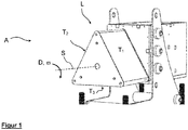
- Fig. 1 shows a sorter A according to the invention, which for integration into a in Fig. 2 indicated conveyor route is suitable.
- the sorter comprises in particular a base body L which can be pivoted about a horizontally oriented pivot axis S which is arranged centrally to the base body L.
- the base body L In cross section to the pivot axis S, the base body L has the contour of an equilateral triangle, each side being formed by a support surface T 1 , T 2 and T 3 .
- the base body L can be pivoted about the pivot axis S in such a way that each of the support surfaces T 1 to T 3 forms the top of the triangular base body L and thus a conveying plane to which a product to be sorted out or conveyed is fed can be ( Fig. 1 shows the base body L in a different rotational position. By pivoting the base body by 60 ° in the direction of rotation D shown, the support surface T 2 would form the above-described conveying plane).
- the support surfaces T 1 to T 3 are designed as low-friction sliding surfaces on which a product can slide along with low frictional resistance.
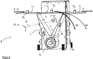
- Fig. 2 shows a modified embodiment of a sorter A according to the invention.
- the base body L (shown open) is formed by three supporting surfaces T 1 to T 3 , which are arranged regularly around the pivot axis S in the manner of an equilateral prism.
- the base body L can be pivoted about the pivot axis D via a drive (not shown in any more detail) such that one of the support surfaces T 1 to T 3 assumes an upper, preferably horizontal, orientation in which the respective support surface comes to lie in an imaginary conveying plane E F.
- the conveyor level E F is preferably at the same height level as a schematically illustrated feed level E Z and a discharge level E A.
- individual products P a , P b , P c are conveyed in a conveying direction F from the feed level E Z via the conveying level E F to the discharge level E A , in order to be fed from there for further processing.
- conveying means such as conveyor belts can be provided to effect or support the transport of the products. In the simplified view according to Fig. 2 these funds are not shown.
- the base body L is rotated by a conveyor belt B which is guided around a drivable drive roller G.
- the drive roller G is arranged on the side of the pivot axis S facing away from the conveying plane E F.
- the conveyor belt B is driven around the base body L in the manner of the two directional arrows shown. It sweeps over the support surface T 1 , which is currently in the Conveyor plane E F is pivoted in and therefore supports the conveyor belt in the vertical direction from below.
- a product P provided by the feed plane E Z can therefore be transported further along the conveyor plane E F and in the conveying direction F by the conveyor belt B and transferred to the discharge plane E A.
- Products P which cannot be sorted out from the product stream, are thus forwarded from the feed level E Z to the discharge level E A.
- the base body L remains unchanged in its rotational position relative to the guide and discharge plane.
- the speed of rotation of the drive roller G is preferably selected such that the speed of the conveyor belt B corresponds to the speed V at which the individual products are fed to the conveying plane E F or are removed therefrom. This guarantees a smooth delivery of the products.
- the outwardly facing surfaces of the support surfaces T 1 to T 3 are preferably designed to be low-friction, so that the conveyor belt B sliding thereon can be driven with only slight frictional resistance.
- a product to be sorted out of the product stream (in Fig. 2
- this product can be sorted out by pivoting the base body L about the pivot axis S.
- the support surface T 1 carrying the product to be sorted out leaves the conveying plane E F.
- the support surface T 1 inclines relative to the conveying direction F, and while the rear end of the support surface T 1 temporarily lifts upward above the conveying plane E F , the front end of the supporting surface T 1 sinks below the conveying plane E F and thus also below that Discharge level E A down.
- a gap is formed between the support surface T 1 and the discharge plane E A , through which the product P B to be sorted out is moved out of the product stream along a sorting-out path W.
- the movement of a product P to be sorted out along the sorting path W can be influenced by the speed of the conveyor belt B and the angular speed of the base body L.
- a relatively simple procedure provides that the speed of the conveyor belt B is kept constant and corresponds approximately to the speed V at which the products P are fed or removed to the sorter along the conveyor path.
- the angular velocity of the base body L can also be chosen to be essentially constant during a pivoting process.
- the angular velocity is preferably specified as a function of the swivel angle in order to be able to determine a specific fall curve for the product to be sorted out.
- a pivoting process preferably does not begin until a product to be sorted out has been moved over half of the support surface supporting the product. If the swiveling process starts earlier, the product would be on that section of the support surface that would initially be lifted upwards by a measure above the conveying surface E F , which would accelerate the product to be sorted out against the direction of gravity and could cause uncontrolled further transport.
- the product to be sorted out has reached the front half of the support surface as seen in the pivoting direction before the start of the pivoting process, it can follow the front half of the support surface that is sloping below the conveying plane E F and be sorted out in a controlled manner.
- the belt speed of the conveyor belt B and the angular speed of the base body L can also be selected such that a product to be sorted out experiences an acceleration force which is exerted on the product by the respective support surface, as the following consideration illustrates:
- a product P moved precisely above the swivel axis S or in the middle of the upper support surface T 1 with the speed V in the conveying direction F would follow gravity from this position in a free, parabolic trajectory if the base body L were not present.
- the free trajectory can only be maintained if the pivoting of the base body L and the speed of the conveyor belt B are matched accordingly.
- the belt speed and the angular speed can influence the path of the product P to be sorted out if these parameters are set differently.
- the belt speed relative to the base body L could be set such that the product to be sorted out is gripped behind by the rear portion of the respective support surface in the circumferential direction and experiences an acceleration force perpendicular to the support surface T from the rotational movement of the base body.
- the current swivel angle and the current position of the product P along the pivoting support surface T the point can be determined at which the product P leaves the pivoting support surface.
- different rejection paths can be defined, one of which is W 'in Fig. 2 is indicated as an example.
Applications Claiming Priority (1)
| Application Number | Priority Date | Filing Date | Title |
|---|---|---|---|
| DE102019100631.7A DE102019100631B3 (de) | 2019-01-11 | 2019-01-11 | Sortierer |
Publications (2)
| Publication Number | Publication Date |
|---|---|
| EP3680032A1 true EP3680032A1 (fr) | 2020-07-15 |
| EP3680032B1 EP3680032B1 (fr) | 2021-06-30 |
Family
ID=69156342
Family Applications (1)
| Application Number | Title | Priority Date | Filing Date |
|---|---|---|---|
| EP20150963.5A Active EP3680032B1 (fr) | 2019-01-11 | 2020-01-09 | Dispositif et procédé de tri |
Country Status (3)
| Country | Link |
|---|---|
| US (1) | US11458509B2 (fr) |
| EP (1) | EP3680032B1 (fr) |
| DE (1) | DE102019100631B3 (fr) |
Families Citing this family (2)
| Publication number | Priority date | Publication date | Assignee | Title |
|---|---|---|---|---|
| CH719753A1 (de) * | 2022-06-03 | 2023-12-15 | Ferag Ag | Transportvorrichtung zum Transport und Beabstanden von Stückgütern. |
| CN115072266B (zh) * | 2022-07-14 | 2023-06-23 | 江苏海事职业技术学院 | 一种用于包裹的运输装置及其运输方法 |
Citations (3)
| Publication number | Priority date | Publication date | Assignee | Title |
|---|---|---|---|---|
| EP0888829A2 (fr) | 1997-06-30 | 1999-01-07 | Team Construct Maschinenbau Gesellschaft m.b.H. | Dispositif de tri d'articles, en particulier de bois débité |
| EP2163315A1 (fr) * | 2008-09-16 | 2010-03-17 | Wincor Nixdorf International GmbH | Dispositif destiné à trier des récipients |
| EP2704109A1 (fr) | 2012-08-28 | 2014-03-05 | Wincor Nixdorf International GmbH | Installation de recyclage de gerbes avec un dispositif de répartition |
Family Cites Families (2)
| Publication number | Priority date | Publication date | Assignee | Title |
|---|---|---|---|---|
| DE3150328A1 (de) * | 1981-12-18 | 1983-06-30 | Manfred 5900 Siegen Wurm | Vorrichtung zum abschieben von gegenstaenden von einer transportbahn |
| US9102336B2 (en) * | 2002-10-16 | 2015-08-11 | Cross Belt Ip, L.L.C. | Portable bin for sortation system |
-
2019
- 2019-01-11 DE DE102019100631.7A patent/DE102019100631B3/de not_active Expired - Fee Related
-
2020
- 2020-01-09 EP EP20150963.5A patent/EP3680032B1/fr active Active
- 2020-01-09 US US16/738,635 patent/US11458509B2/en active Active
Patent Citations (3)
| Publication number | Priority date | Publication date | Assignee | Title |
|---|---|---|---|---|
| EP0888829A2 (fr) | 1997-06-30 | 1999-01-07 | Team Construct Maschinenbau Gesellschaft m.b.H. | Dispositif de tri d'articles, en particulier de bois débité |
| EP2163315A1 (fr) * | 2008-09-16 | 2010-03-17 | Wincor Nixdorf International GmbH | Dispositif destiné à trier des récipients |
| EP2704109A1 (fr) | 2012-08-28 | 2014-03-05 | Wincor Nixdorf International GmbH | Installation de recyclage de gerbes avec un dispositif de répartition |
Also Published As
| Publication number | Publication date |
|---|---|
| EP3680032B1 (fr) | 2021-06-30 |
| US20200222947A1 (en) | 2020-07-16 |
| DE102019100631B3 (de) | 2020-03-26 |
| US11458509B2 (en) | 2022-10-04 |
Similar Documents
| Publication | Publication Date | Title |
|---|---|---|
| EP2054330B1 (fr) | Dispositif et procédé pour le transfert d'un groupe de produits d'un convoyeur d'entrée à un convoyeur de sortie | |
| EP2995183B1 (fr) | Dispositif de dosage | |
| EP3680032B1 (fr) | Dispositif et procédé de tri | |
| EP3357839A1 (fr) | Procédé et système de transport destinés à manipuler un flux de produits initial | |
| EP2478782B1 (fr) | Dispositif de transport pour produits en forme de tige de l'industrie de traitement du tabac | |
| DE102014117392A1 (de) | Fördervorrichtung | |
| EP3208001B1 (fr) | Séparateur pneumatique doté d'une triple séparation | |
| EP3162739B1 (fr) | Dispositif et procede de transfert de portions de saucisses | |
| DE3241100A1 (de) | Vorrichtung zum abweisen von stueckguetern, insbesondere von paketen, oder zum ausschleusen einzelner stueckgueter aus einer reihe von hintereinander auf einem zufuehrband transportierten stueckguetern | |
| CH700565A1 (de) | Fördervorrichtung mit einem Hauptfördermittel und einem Querfördermittel. | |
| EP2945891B1 (fr) | Installation de transport | |
| CH715814A1 (de) | Übergabesystem für Förderobjekte mit einer Fördereinrichtung und einer Übergabevorrichtung. | |
| EP4001187A1 (fr) | Procédé de positionnement transversal d'un article à transporter | |
| EP2002405A1 (fr) | Unite de transport dans un systeme de recuperation de produits vides | |
| EP0739834A2 (fr) | Dispositif pour tourner des produits pendant le processus de transport | |
| EP1655246B1 (fr) | Dispositif et procédure pour diviser un flot des produits à l'aide d'un glissoir | |
| DE102021116619A1 (de) | Einlege-Zufuhreinheit sowie Verfahren für ihren Betrieb | |
| EP2919588B1 (fr) | Installation et procédé pour traiter des produits alimentaires transportés dans un flux de produits | |
| CH660312A5 (de) | Vorrichtung zum absondern fehlerhafter flacher dauerbackwaren. | |
| EP2298078A2 (fr) | Dispositif pour le pétrissage de portions de pâte | |
| DE202016105590U1 (de) | Vorrichtung zum Sortieren mit Stückgütern mit Dosiereinrichtung | |
| CH687964A5 (de) | Vorrichtung zum Be- und Entladen von Zweischeiben-Lopp- und Honmaschinen. | |
| DE102020129751A1 (de) | Aufschneide-Maschine | |
| DE102021100897A1 (de) | Aufschneide-Maschine | |
| DE102021102247A1 (de) | Verfahren zum Falten einer abgetrennten Scheibe sowie hierfür ausgebildete Aufschneide-Maschine |
Legal Events
| Date | Code | Title | Description |
|---|---|---|---|
| PUAI | Public reference made under article 153(3) epc to a published international application that has entered the european phase |
Free format text: ORIGINAL CODE: 0009012 |
|
| STAA | Information on the status of an ep patent application or granted ep patent |
Free format text: STATUS: THE APPLICATION HAS BEEN PUBLISHED |
|
| AK | Designated contracting states |
Kind code of ref document: A1 Designated state(s): AL AT BE BG CH CY CZ DE DK EE ES FI FR GB GR HR HU IE IS IT LI LT LU LV MC MK MT NL NO PL PT RO RS SE SI SK SM TR |
|
| AX | Request for extension of the european patent |
Extension state: BA ME |
|
| STAA | Information on the status of an ep patent application or granted ep patent |
Free format text: STATUS: REQUEST FOR EXAMINATION WAS MADE |
|
| 17P | Request for examination filed |
Effective date: 20200807 |
|
| RBV | Designated contracting states (corrected) |
Designated state(s): AL AT BE BG CH CY CZ DE DK EE ES FI FR GB GR HR HU IE IS IT LI LT LU LV MC MK MT NL NO PL PT RO RS SE SI SK SM TR |
|
| GRAP | Despatch of communication of intention to grant a patent |
Free format text: ORIGINAL CODE: EPIDOSNIGR1 |
|
| STAA | Information on the status of an ep patent application or granted ep patent |
Free format text: STATUS: GRANT OF PATENT IS INTENDED |
|
| RIC1 | Information provided on ipc code assigned before grant |
Ipc: B65G 47/96 20060101ALI20210122BHEP Ipc: B07C 5/36 20060101AFI20210122BHEP |
|
| INTG | Intention to grant announced |
Effective date: 20210208 |
|
| GRAS | Grant fee paid |
Free format text: ORIGINAL CODE: EPIDOSNIGR3 |
|
| GRAA | (expected) grant |
Free format text: ORIGINAL CODE: 0009210 |
|
| STAA | Information on the status of an ep patent application or granted ep patent |
Free format text: STATUS: THE PATENT HAS BEEN GRANTED |
|
| AK | Designated contracting states |
Kind code of ref document: B1 Designated state(s): AL AT BE BG CH CY CZ DE DK EE ES FI FR GB GR HR HU IE IS IT LI LT LU LV MC MK MT NL NO PL PT RO RS SE SI SK SM TR |
|
| REG | Reference to a national code |
Ref country code: CH Ref legal event code: EP |
|
| REG | Reference to a national code |
Ref country code: DE Ref legal event code: R096 Ref document number: 502020000068 Country of ref document: DE Ref country code: AT Ref legal event code: REF Ref document number: 1405861 Country of ref document: AT Kind code of ref document: T Effective date: 20210715 |
|
| REG | Reference to a national code |
Ref country code: IE Ref legal event code: FG4D Free format text: LANGUAGE OF EP DOCUMENT: GERMAN |
|
| REG | Reference to a national code |
Ref country code: LT Ref legal event code: MG9D |
|
| PG25 | Lapsed in a contracting state [announced via postgrant information from national office to epo] |
Ref country code: BG Free format text: LAPSE BECAUSE OF FAILURE TO SUBMIT A TRANSLATION OF THE DESCRIPTION OR TO PAY THE FEE WITHIN THE PRESCRIBED TIME-LIMIT Effective date: 20210930 Ref country code: FI Free format text: LAPSE BECAUSE OF FAILURE TO SUBMIT A TRANSLATION OF THE DESCRIPTION OR TO PAY THE FEE WITHIN THE PRESCRIBED TIME-LIMIT Effective date: 20210630 Ref country code: HR Free format text: LAPSE BECAUSE OF FAILURE TO SUBMIT A TRANSLATION OF THE DESCRIPTION OR TO PAY THE FEE WITHIN THE PRESCRIBED TIME-LIMIT Effective date: 20210630 |
|
| REG | Reference to a national code |
Ref country code: NL Ref legal event code: MP Effective date: 20210630 |
|
| PG25 | Lapsed in a contracting state [announced via postgrant information from national office to epo] |
Ref country code: GR Free format text: LAPSE BECAUSE OF FAILURE TO SUBMIT A TRANSLATION OF THE DESCRIPTION OR TO PAY THE FEE WITHIN THE PRESCRIBED TIME-LIMIT Effective date: 20211001 Ref country code: LV Free format text: LAPSE BECAUSE OF FAILURE TO SUBMIT A TRANSLATION OF THE DESCRIPTION OR TO PAY THE FEE WITHIN THE PRESCRIBED TIME-LIMIT Effective date: 20210630 Ref country code: NO Free format text: LAPSE BECAUSE OF FAILURE TO SUBMIT A TRANSLATION OF THE DESCRIPTION OR TO PAY THE FEE WITHIN THE PRESCRIBED TIME-LIMIT Effective date: 20210930 Ref country code: SE Free format text: LAPSE BECAUSE OF FAILURE TO SUBMIT A TRANSLATION OF THE DESCRIPTION OR TO PAY THE FEE WITHIN THE PRESCRIBED TIME-LIMIT Effective date: 20210630 Ref country code: RS Free format text: LAPSE BECAUSE OF FAILURE TO SUBMIT A TRANSLATION OF THE DESCRIPTION OR TO PAY THE FEE WITHIN THE PRESCRIBED TIME-LIMIT Effective date: 20210630 |
|
| PG25 | Lapsed in a contracting state [announced via postgrant information from national office to epo] |
Ref country code: SM Free format text: LAPSE BECAUSE OF FAILURE TO SUBMIT A TRANSLATION OF THE DESCRIPTION OR TO PAY THE FEE WITHIN THE PRESCRIBED TIME-LIMIT Effective date: 20210630 Ref country code: RO Free format text: LAPSE BECAUSE OF FAILURE TO SUBMIT A TRANSLATION OF THE DESCRIPTION OR TO PAY THE FEE WITHIN THE PRESCRIBED TIME-LIMIT Effective date: 20210630 Ref country code: NL Free format text: LAPSE BECAUSE OF FAILURE TO SUBMIT A TRANSLATION OF THE DESCRIPTION OR TO PAY THE FEE WITHIN THE PRESCRIBED TIME-LIMIT Effective date: 20210630 Ref country code: PT Free format text: LAPSE BECAUSE OF FAILURE TO SUBMIT A TRANSLATION OF THE DESCRIPTION OR TO PAY THE FEE WITHIN THE PRESCRIBED TIME-LIMIT Effective date: 20211102 Ref country code: CZ Free format text: LAPSE BECAUSE OF FAILURE TO SUBMIT A TRANSLATION OF THE DESCRIPTION OR TO PAY THE FEE WITHIN THE PRESCRIBED TIME-LIMIT Effective date: 20210630 Ref country code: SK Free format text: LAPSE BECAUSE OF FAILURE TO SUBMIT A TRANSLATION OF THE DESCRIPTION OR TO PAY THE FEE WITHIN THE PRESCRIBED TIME-LIMIT Effective date: 20210630 Ref country code: EE Free format text: LAPSE BECAUSE OF FAILURE TO SUBMIT A TRANSLATION OF THE DESCRIPTION OR TO PAY THE FEE WITHIN THE PRESCRIBED TIME-LIMIT Effective date: 20210630 Ref country code: ES Free format text: LAPSE BECAUSE OF FAILURE TO SUBMIT A TRANSLATION OF THE DESCRIPTION OR TO PAY THE FEE WITHIN THE PRESCRIBED TIME-LIMIT Effective date: 20210630 |
|
| PG25 | Lapsed in a contracting state [announced via postgrant information from national office to epo] |
Ref country code: PL Free format text: LAPSE BECAUSE OF FAILURE TO SUBMIT A TRANSLATION OF THE DESCRIPTION OR TO PAY THE FEE WITHIN THE PRESCRIBED TIME-LIMIT Effective date: 20210630 |
|
| REG | Reference to a national code |
Ref country code: DE Ref legal event code: R097 Ref document number: 502020000068 Country of ref document: DE |
|
| PG25 | Lapsed in a contracting state [announced via postgrant information from national office to epo] |
Ref country code: DK Free format text: LAPSE BECAUSE OF FAILURE TO SUBMIT A TRANSLATION OF THE DESCRIPTION OR TO PAY THE FEE WITHIN THE PRESCRIBED TIME-LIMIT Effective date: 20210630 |
|
| PLBE | No opposition filed within time limit |
Free format text: ORIGINAL CODE: 0009261 |
|
| STAA | Information on the status of an ep patent application or granted ep patent |
Free format text: STATUS: NO OPPOSITION FILED WITHIN TIME LIMIT |
|
| PG25 | Lapsed in a contracting state [announced via postgrant information from national office to epo] |
Ref country code: AL Free format text: LAPSE BECAUSE OF FAILURE TO SUBMIT A TRANSLATION OF THE DESCRIPTION OR TO PAY THE FEE WITHIN THE PRESCRIBED TIME-LIMIT Effective date: 20210630 |
|
| 26N | No opposition filed |
Effective date: 20220331 |
|
| PG25 | Lapsed in a contracting state [announced via postgrant information from national office to epo] |
Ref country code: IT Free format text: LAPSE BECAUSE OF FAILURE TO SUBMIT A TRANSLATION OF THE DESCRIPTION OR TO PAY THE FEE WITHIN THE PRESCRIBED TIME-LIMIT Effective date: 20210630 |
|
| PG25 | Lapsed in a contracting state [announced via postgrant information from national office to epo] |
Ref country code: MC Free format text: LAPSE BECAUSE OF FAILURE TO SUBMIT A TRANSLATION OF THE DESCRIPTION OR TO PAY THE FEE WITHIN THE PRESCRIBED TIME-LIMIT Effective date: 20210630 |
|
| REG | Reference to a national code |
Ref country code: BE Ref legal event code: MM Effective date: 20220131 |
|
| PG25 | Lapsed in a contracting state [announced via postgrant information from national office to epo] |
Ref country code: LU Free format text: LAPSE BECAUSE OF NON-PAYMENT OF DUE FEES Effective date: 20220109 |
|
| PG25 | Lapsed in a contracting state [announced via postgrant information from national office to epo] |
Ref country code: FR Free format text: LAPSE BECAUSE OF NON-PAYMENT OF DUE FEES Effective date: 20220131 Ref country code: BE Free format text: LAPSE BECAUSE OF NON-PAYMENT OF DUE FEES Effective date: 20220131 |
|
| PG25 | Lapsed in a contracting state [announced via postgrant information from national office to epo] |
Ref country code: IE Free format text: LAPSE BECAUSE OF NON-PAYMENT OF DUE FEES Effective date: 20220109 |
|
| PG25 | Lapsed in a contracting state [announced via postgrant information from national office to epo] |
Ref country code: LT Free format text: LAPSE BECAUSE OF FAILURE TO SUBMIT A TRANSLATION OF THE DESCRIPTION OR TO PAY THE FEE WITHIN THE PRESCRIBED TIME-LIMIT Effective date: 20210630 |
|
| REG | Reference to a national code |
Ref country code: CH Ref legal event code: PL |
|
| PG25 | Lapsed in a contracting state [announced via postgrant information from national office to epo] |
Ref country code: LI Free format text: LAPSE BECAUSE OF NON-PAYMENT OF DUE FEES Effective date: 20230131 Ref country code: CH Free format text: LAPSE BECAUSE OF NON-PAYMENT OF DUE FEES Effective date: 20230131 |
|
| PG25 | Lapsed in a contracting state [announced via postgrant information from national office to epo] |
Ref country code: MK Free format text: LAPSE BECAUSE OF FAILURE TO SUBMIT A TRANSLATION OF THE DESCRIPTION OR TO PAY THE FEE WITHIN THE PRESCRIBED TIME-LIMIT Effective date: 20210630 Ref country code: CY Free format text: LAPSE BECAUSE OF FAILURE TO SUBMIT A TRANSLATION OF THE DESCRIPTION OR TO PAY THE FEE WITHIN THE PRESCRIBED TIME-LIMIT Effective date: 20210630 |
|
| PGFP | Annual fee paid to national office [announced via postgrant information from national office to epo] |
Ref country code: DE Payment date: 20240102 Year of fee payment: 5 |