EP3673968A1 - Schlammbehandlungsvorrichtung - Google Patents
Schlammbehandlungsvorrichtung Download PDFInfo
- Publication number
- EP3673968A1 EP3673968A1 EP17922196.5A EP17922196A EP3673968A1 EP 3673968 A1 EP3673968 A1 EP 3673968A1 EP 17922196 A EP17922196 A EP 17922196A EP 3673968 A1 EP3673968 A1 EP 3673968A1
- Authority
- EP
- European Patent Office
- Prior art keywords
- straight line
- engagement portion
- sludge
- engagement
- driving wheel
- Prior art date
- Legal status (The legal status is an assumption and is not a legal conclusion. Google has not performed a legal analysis and makes no representation as to the accuracy of the status listed.)
- Granted
Links
Images





Classifications
-
- B—PERFORMING OPERATIONS; TRANSPORTING
- B01—PHYSICAL OR CHEMICAL PROCESSES OR APPARATUS IN GENERAL
- B01D—SEPARATION
- B01D21/00—Separation of suspended solid particles from liquids by sedimentation
- B01D21/18—Construction of the scrapers or the driving mechanisms for settling tanks
- B01D21/20—Driving mechanisms
-
- B—PERFORMING OPERATIONS; TRANSPORTING
- B01—PHYSICAL OR CHEMICAL PROCESSES OR APPARATUS IN GENERAL
- B01D—SEPARATION
- B01D21/00—Separation of suspended solid particles from liquids by sedimentation
- B01D21/18—Construction of the scrapers or the driving mechanisms for settling tanks
-
- B—PERFORMING OPERATIONS; TRANSPORTING
- B01—PHYSICAL OR CHEMICAL PROCESSES OR APPARATUS IN GENERAL
- B01D—SEPARATION
- B01D21/00—Separation of suspended solid particles from liquids by sedimentation
- B01D21/24—Feed or discharge mechanisms for settling tanks
- B01D21/245—Discharge mechanisms for the sediments
Definitions
- the present invention relates to a sludge treatment apparatus for treating sludge settled in a water tank, and more particularly, to a forward movement mechanism for a scraper that draws up the sludge.
- Patent Literature 1 discloses an example of a sludge scraping apparatus including an endless circulation driving member wound around a pair of wheels. Pulling power is transmitted via this circulation driving member to cause the forward movement of the scraper.
- a traveling body 20 including the scraper is provided with engagement reception surfaces 31 and 32 that come into contact with an engagement portion 33 on an endless circulation driving member 19.
- the endless circulation driving member 19 continuously rotates with the rotation direction fixed. As a result, the engagement portions 33 moving along the endless circulation driving member 19 alternately come into contact with the engagement reception surfaces 31 and 32, and the traveling body 20 moves alternately in one direction and the opposite direction.
- Patent Literature 1 Utility model registration No. 2603973
- the traveling direction is reversed at the end of the movable range of the scraper.
- the traveling direction cannot be reversed in the middle of the movable range, in other words, in the middle of the movement of the sludge drawing tool.
- an object of the present invention is to make the traveling direction reversible regardless of the position of the scraper.
- the present invention provides a sludge treatment apparatus including a pair of wheels including a driving wheel; a power transmission member that is endlessly formed and is provided with a pulling portion; and a moving body provided with first to fourth engagement portions.
- the power transmission member is wound around the pair of wheels, and includes a first straight line and a second straight line extending between the pair of wheels.
- the moving body is provided to be able to move forward between the pair of wheels and includes a scraper for drawing in sludge.
- the first to the fourth engagement portions have a shape enabling the pulling portion that circumferentially moves along the power transmission member to engage with and to be disengaged from the first to the fourth engagement portions.
- the first engagement portion is provided near the first straight line, and comes into contact with the pulling portion moving on the first straight line in one direction to make the moving body move in the one direction when the driving wheel rotates in one direction.
- the second engagement portion is provided near the second straight line, and comes into contact with the pulling portion moving in an opposite direction on the second straight line to make the moving body move in the opposite direction when the driving wheel rotates in the one direction.
- the third engagement portion is provided near the first straight line and at a position different from the first engagement portion, and comes into contact with the pulling portion moving in the opposite direction on the first straight line to move the moving body in the opposite direction when the driving wheel rotates in an opposite direction.
- the fourth engagement portion is provided near the second straight line and at a position different from the second engagement portion, and comes into contact with the pulling portion moving in the one direction on the second straight line to make the moving body move in the one direction when the driving wheel rotates in the opposite direction.
- the third engagement portion is preferably provided at a position opposite to the second engagement portion, and the fourth engagement portion is preferably provided at a position opposite to the first engagement portion. Furthermore, the third engagement portion is preferably shaped to be line symmetrical with the second engagement portion with respect to an axis of symmetry connecting center axes of the pair of wheels, and the fourth engagement portion is preferably shaped to be line symmetrical with the first engagement portion with respect to the axis of symmetry.
- the moving body may include a carriage to which the scraper is rotatably attached, a slide portion, and a link mechanism.
- the carriage has a wheel for moving on a rail.
- the slide portion is provided to the carriage to be slidable within a predetermined movable range, and includes the first to the fourth engagement portions.
- the link mechanism couples the slide portion and the scraper to each other and makes the scraper rotate in accordance with sliding of the slide portion with respect to the carriage.
- the slide portion is preferably attached on a lower side of the carriage, and the power transmission member is preferably provided through an inside of the slide portion.
- the moving body including the scraper moves forward with the pulling portion alternately coming into contact with the first and the second engagement portions when the driving wheel rotates in one direction, and moves forward with the pulling portion alternately coming into contact with the third and the fourth engagement portions when the driving wheel rotates in the opposite direction.
- the driving wheel is reversed.
- the pulling portion that has been in contact with one engagement portion moves on the straight line and comes into contact with another engagement portion (the third engagement portion, for example) arranged on the same straight line, so that the traveling direction of the moving body is reversed.
- the traveling direction can be reversed at any desired position during the movement of the moving body.
- Fig. 1 is a top view of a sludge treatment apparatus according to the present embodiment.
- the sludge treatment apparatus 1 is arranged on the bottom of a tank containing treatment target water, for drawing up and discharging the sludge settled in the tank using a scraper 8.
- the sludge treatment apparatus 1 mainly includes a sludge drawing tool 2 that is a moving body having the scraper 8 for drawing up the sludge, rails 3, a pair of wheels 4a and 4b, and a chain 5 serving as a power transmission member.
- the present embodiment features the following three points.
- the first point is that the sludge drawing tool 2 makes forward movement between the pair of wheels 4a and 4b, that is, moves alternately in a drawing direction and a returning direction, simply by continuously rotating the driving wheel 4a in one direction.
- the second point is that the scraper 8 that is a component of the sludge drawing tool 2 moves upward and downward in accordance with the traveling direction of the sludge drawing tool 2. Specifically, the scraper 8 moves downward in response to the movement in the drawing direction for drawing in the sludge, and moves upward in response to the movement in the returning direction.
- the third point is that the movement direction of the sludge drawing tool 2 can be freely switched, even during the movement of the sludge drawing tool 2. Thus, reversing to the returning direction can be implemented in the middle of the movement in the drawing direction, and reversing to the drawing direction can be implemented in the middle of the movement in the returning direction.
- the two rails 3 are arranged in parallel to each other on the bottom of the tank. At one end of the rails 3, that is, in an end portion in the drawing direction, the bottom of the tank is depressed to be formed into a pit for discharging the sludge.
- the pair of wheels 4a and 4b are provided at both ends of the rails 3.
- the driving wheel 4a is disposed at the end in the drawing direction
- the driven wheel 4b is disposed at the end in the returning direction. It is to be noted that, driving force can also be transmitted to the sludge drawing tool 2 with the wheels 4a and 4b arranged oppositely, that is, with the driving wheel 4a disposed at the end in the returning direction.
- the chain 5 is an endless power transmission member that is wound around the pair of wheels 4a and 4b.
- the chain 5 includes two semicircular arc-shaped curved lines extending along the outer circumferences of the respective wheels 4a and 4b and two straight lines L1 and L2 extending between the wheels 4a and 4b.
- a belt or the like may be used instead of the chain 5 as a member for transmitting driving force to the sludge drawing tool 2.
- the driving force from a driving source such as a motor (not illustrated) is transmitted to the driving wheel 4a via a chain provided separately from the chain 5, to rotate the driving wheel 4a.
- a driving source such as a motor (not illustrated)
- the driving wheel 4a rotates, the chain 5 wound around the wheels 4a and 4b moves, so that the driving force is transmitted to the sludge drawing tool 2.
- the driving wheel 4a rotate in any of the normal direction and the reverse direction, by switching the rotation direction of the driving source.
- Power transmission from the driving source to the driving wheel 4a via the chain provides an advantage that the number of sludge treatment apparatuses 1 arranged in parallel can be adjusted flexibly and inexpensively.
- the driving wheel 4a may be directly attached to a rotation shaft of the driving source arranged above the driving wheel 4a.
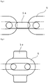
- Fig. 2 is a top view of the chain 5, and Fig. 3 is a side view thereof.
- a pulling portion 5a having a pin-like shape protruding in a predetermined direction is attached to a part of the chain 5 by welding or the like.
- the pulling portion 5a is provided so as to protrude upward in the top view of Fig. 1 , but may be provided so as to protrude laterally outward in the figure.
- the pulling portion 5a may have any shape as long as engagement portions 7a to 7d described later can be free engage therewith and disengaged therefrom.
- An example such a shape includes a hook shape.
- the pulling portion 5a can circumferentially move along the chain 5 as the driving wheel 4a rotates.
- the sludge drawing tool 2 is arranged on the two rails 3, and can freely move forward in the drawing direction and in the returning direction between the pair of wheels 4a and 4b. As illustrated in Fig. 1 , the sludge drawing tool 2 is provided with the four engagement portions 7a to 7d, and is pulled in the drawing direction and in the returning direction with the pulling portion 5a, circumferentially moving along the chain 5, coming into contact with any of the engagement portions 7a to 7d.
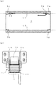
- Fig. 4 is a side view of the sludge drawing tool 2.
- the sludge drawing tool 2 mainly includes a carriage 6, a slide portion 7, and the scraper 8.
- the carriage 6 includes a plurality of wheels 6a for moving on the two rails 3, to be movable on the rail 3. Furthermore, the carriage 6 has a lower surface provided with a protruding portion 6b protruding downward.
- the slide portion 7 is slidably attached to the lower side of the carriage 6.
- the slide portion 7 has an upper surface provided with a depression extending for a predetermined length, along the movement direction of the sludge drawing tool 2, to serve as a guide groove 7e.
- the protruding portion 6b on the carriage 6 side is inserted in the guide groove 7e.
- the movable (slidable) range of the slide portion 7 with respect to the carriage 6 is limited to a range defined by the guide groove 7e.
- Fig. 5 is a schematic top view of the slide portion 7.
- the chain 5 is provided through the inside of the slide portion 7 having both side surfaces provided with the above-described four engagement portions 7a to 7d.
- These engagement portions 7a to 7d protrude toward the chain 5, and are shaped to enable the pulling portion 5a, circumferentially moving along the chain 5, to be engaged therewith and to be disengaged therefrom.
- the engagement portions 7a and 7c are provided at different positions near the straight line L1, and the engagement portions 7b and 7d are provided at different positions near the straight line L2.
- the engagement portions 7a and 7d are provided at opposite positions, and have shapes that are line-symmetric about an axis of symmetry P connecting the center axes of the pair of wheels 4a and 4b.
- the engagement portions 7b and 7c are provided at opposite positions and have shapes that are line-symmetric about the axis of symmetry P.
- the slide portion 7 (sludge drawing tool 2) is pulled by means of the engagement portions 7a and 7b. Specifically, when the driving wheel 4a rotates in the normal direction, the engagement portion 7a comes into contact with the pulling portion 5a moving in the drawing direction on the straight line L1, to make the slide portion 7 move in the drawing direction. The engagement portion 7b comes into contact with the pulling portion 5a moving on the straight line L2 in the returning direction, to make the slide portion 7 move in the returning direction.
- the slide portion 7 (sludge drawing tool 2) is pulled by means of the engagement portions 7c and 7d.
- the engagement portion 7c comes into contact with the pulling portion 5a moving in the returning direction on the straight line L1, to make the slide portion 7 move in the returning direction.
- the engagement portion 7d comes into contact with the pulling portion 5a moving on the straight line L2 in the drawing direction, to make the slide portion 7 move in the drawing direction.
- the scraper 8 extends substantially orthogonally to the rails 3, and has a shape to draw in the sludge settled in the tank.
- the scraper 8 is attached to the carriage 6 via a rotation shaft 9, as illustrated in Fig. 4 .
- a link mechanism 10 is provided between the slide portion 7 and the scraper 8 to couple these elements to each other.
- the link mechanism 10 rotates the scraper 8 in accordance with the sliding of the slide portion 7 with respect to the carriage 6.
- the scraper 8 moves upward and downward. Specifically, as illustrated in Fig. 6 , in a state where the slide portion 7 is pulled out toward the right side with respect to the carriage 6 (a state indicated by a broken line), the scraper 8 is lowered.
- the scraper 8 gradually rises.
- the scraper 8 is completely raised.
- the scraper 8 is gradually lowered as the slide portion 7 is pulled out toward the right side after being pushed toward the left side relative to the carriage 6 to completely raise the scraper 8. Then, when the slide portion 7 is completely pulled out, the scraper 8 is completely lowered.
- FIG. 7 is an explanatory view of a forward movement of the sludge drawing tool 2 caused by the forward rotation of the driving wheel 4a.
- the pulling portion 5a moving on the straight line L1 of the chain 5 in the drawing direction comes into contact with the engagement portion 7a.
- the slide portion 7 sludge drawing tool 2 moves in the drawing direction until the pulling portion 5a reaches the end of the straight line L1, with the lowered state (a state for scraping the sludge) of the scraper 8 maintained.
- the pulling portion 5a Upon reaching the end of the straight line L1, the pulling portion 5a starts to move on the curved line along the outer circumference of the driving wheel 4a, to gradually move away from the engagement portion 7a. Then, when the pulling portion 5a reaches a position P1 to be disengaged from the engagement portion 7a, the slide portion 7 (sludge drawing tool 2) stops while maintaining the lowered state (end position).
- the pulling portion 5a After moving on the curved line, the pulling portion 5a enters the straight line L2. In this process, the entrance of the pulling portion 5a will not be hindered by the engagement portion 7d at the end position where the slide portion 7 has stopped, because the engagement portions 7a and 7d have the same protruding height. Then, the pulling portion 5a reaches a position P2 on the straight line L2 to come into contact with the engagement portion 7b. Thus, the slide portion 7 starts to move in the returning direction that is opposite to the drawing direction. The resistance against the sliding of the slide portion 7 on the carriage 6 is smaller than the resistance against the movement the carriage 6 on the rail 3. Thus, the movement of the pulling portion 5a after passing through the position P2 results in the slide portion 7 sliding with respect to the carriage 6.
- the sludge drawing tool 2 stops in the raised state. Then, the scraper 8 starts to be lowered when the pulling portion 5a comes into contact with the engagement portion 7a. When the scraper 8 is completely lowered, the sludge drawing tool 2 moves in the drawing direction.
- the forward movement of the sludge drawing tool 2 involving the upward and downward movement of the scraper 8 can be automatically implemented simply by rotating the driving wheel 4a in a predetermined direction.
- This is advantageous in that no sensor needs to be provided for detecting the end position of the sludge drawing tool 2 and that the driving wheel 4a needs not to be alternately rotated in the forward and the reverse directions.
- Fig. 8 is an explanatory view illustrating how the sludge drawing tool 2 is reversed in the middle of a movement.
- the pulling portion 5a moving on the straight line L1 of the chain 5 in the drawing direction comes into contact with the engagement portion 7a.
- the slide portion 7 sludge drawing tool 2 moves in the drawing direction with the lowered state of the scraper 8 maintained.
- the driving wheel 4a is reversed during this movement, the pulling portion 5a on the straight line L1 starts to move in the opposite direction.
- the pulling portion 5a is disengaged from the engagement portion 7a, and the sludge drawing tool 2 stops with the lowered state maintained.
- the pulling portion 5a moving on the straight line L1 reaches a position P3 to come into contact with the engagement portion 7c arranged on the same straight line L1.
- the scraper 8 starts to rise.
- the scraper 8 is completely raised, the sludge drawing tool 2 moves in the returning direction.
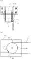
- FIG. 9 is a front view of a wheel with a stopper as an example
- Fig. 10 is a side view thereof.
- This stopper 11 is made of metal and has a pair of arms 11a and 11b and a contact portion 11c.
- the pair of arms 11a and 11b are eccentrically and rotatably mounted on the rotation shaft of the wheel 6a.
- the contact portion 11c is integrally provided to the tips of these arms 11a and 11b, to come into contact with the rails 3 for generating frictional force (braking force).
- the contact portion 11c protrudes beyond the outer circumference of the wheel 6a, and has a curved outer circumference surface processed (knurled) to have recesses and protrusions for applying strong braking force to the carriage 6.
- Fig. 11 is a diagram illustrating an operation of the stopper 11.
- the stopper 11 is positioned on the travelling direction side (obliquely forward) at a timing when the sludge drawing tool 2 is reversed.
- the carriage 6 receives a predetermined amount of braking force due to the frictional force between the stopper 11 and the rails 3 based on the weight of the stopper 11 and the effect of the stopper 11, positioned obliquely forward, being stuck to the rails 3.
- the carriage 6 stops without being dragged by the slide portion 7, meaning that only the slide portion 7 slides until reaching the end of the movable range.
- Fig. 12 is a front view of a wheel with a stopper according to a modification.
- This stopper 11' has one arm 11a with a distal end surface provided with the above-mentioned contact portion 11c.
- the contact portion 11c has a smaller are than in the configuration of Fig. 9 , but can guarantee a certain amount of braking force.
- the sludge drawing tool 2 moves forward with the pulling portion 5a alternately coming into contact with the engagement portions 7a and 7b when the driving wheel 4a rotates in the forward direction, and moves forward with the pulling portion 5a alternately coming into contact with the engagement portions 7c and 7d when the driving wheel 5a rotates in the reverse direction.
- the driving wheel 4a is reversed.
- the pulling portion 5a that has been in contact with one engagement portion (7a for example) moves on the straight line and comes into contact with another engagement portion (7c for example) arranged on same the straight line, so that the traveling direction of the sludge drawing tool 2 is reversed.
- the traveling direction can be reversed at any desired position during the movement of the sludge drawing tool 2. This is advantageous in terms of improving the maintainability of the sludge treatment apparatus 1 is improved and making an unexpected situation easier to be handled.
- the sludge drawing tool 2 is configured as follows. Specifically, the slide portion 7 slidable with respect to the carriage 6 is provided for causing the pulling of the sludge drawing tool 2 with the slide portion 7 as starting point.
- the link mechanism 10 is provided to couple the slide portion 7 and the scraper 8 to each other.
- automatic upward and downward movement of the scraper 8 linked with the forward movement of the sludge drawing tool 2 can be implemented using the power transmitted via the chain 5.
- the upward and downward movement can be implemented with a mechanical mechanism without providing the sludge drawing tool 2 with a driving source (such as a motor). This is advantageous in that the sludge treatment apparatus 1 can have a higher durability and maintainability.
- the sludge drawing tool 2 is further configured as follows. Specifically, the slide portion 7 is provided on the lower side of the carriage 6, and the chain 5 is provided through the inside of the slide portion 7. As a result, the sludge drawing tool 2 can have a low height, so as to be effectively prevented from interfering with other members in the tank (such as an inclined plate enabling swift sinking of the sludge in the water).
- the sludge drawing tool 2 is provided with the raising and lowering mechanism including the slide portion 7 and the link mechanism 10 so that the scraper 8 can be raised and lowered with the power supplied from the chain 5.
- a raising and lowering mechanism needs not to be provided in cases such as a case where the power is externally supplied from a system different from the chain 5 or a case where the sludge drawing tool 2 is provided with a driving source for the upward and downward movement.
Landscapes
- Chemical & Material Sciences (AREA)
- Chemical Kinetics & Catalysis (AREA)
- Treatment Of Sludge (AREA)
- Removal Of Floating Material (AREA)
- Chain Conveyers (AREA)
- Platform Screen Doors And Railroad Systems (AREA)
Applications Claiming Priority (1)
| Application Number | Priority Date | Filing Date | Title |
|---|---|---|---|
| PCT/JP2017/030064 WO2019038842A1 (ja) | 2017-08-23 | 2017-08-23 | 汚泥処理装置 |
Publications (3)
| Publication Number | Publication Date |
|---|---|
| EP3673968A1 true EP3673968A1 (de) | 2020-07-01 |
| EP3673968A4 EP3673968A4 (de) | 2021-03-10 |
| EP3673968B1 EP3673968B1 (de) | 2023-05-10 |
Family
ID=65438499
Family Applications (1)
| Application Number | Title | Priority Date | Filing Date |
|---|---|---|---|
| EP17922196.5A Active EP3673968B1 (de) | 2017-08-23 | 2017-08-23 | Schlammbehandlungsvorrichtung |
Country Status (6)
| Country | Link |
|---|---|
| US (1) | US10905974B2 (de) |
| EP (1) | EP3673968B1 (de) |
| JP (1) | JP6814297B2 (de) |
| CA (1) | CA3072147A1 (de) |
| ES (1) | ES2956944T3 (de) |
| WO (1) | WO2019038842A1 (de) |
Families Citing this family (1)
| Publication number | Priority date | Publication date | Assignee | Title |
|---|---|---|---|---|
| EP4483981A4 (de) * | 2022-03-31 | 2026-01-07 | Suido Kiko Kk | Schlammbehandlungsvorrichtung |
Family Cites Families (14)
| Publication number | Priority date | Publication date | Assignee | Title |
|---|---|---|---|---|
| US1918742A (en) * | 1931-06-15 | 1933-07-18 | Henry E Elrod | Settling tank |
| US2101079A (en) * | 1934-10-03 | 1937-12-07 | Dorr Co Inc | Sedimentation apparatus |
| DE1658105A1 (de) * | 1967-02-17 | 1970-05-06 | Passavant Werke | Raeumvorrichtung fuer Absetzbecken mit mindestens einem heb- und senkbaren Raeumschild |
| DE2211922C3 (de) * | 1972-03-11 | 1974-09-26 | Ruhrkohle Ag, 4300 Essen | Rundgliederkette für Kratzerförderer |
| JPS51117447A (en) | 1975-04-08 | 1976-10-15 | Hitachi Plant Eng & Constr Co Ltd | Slurry scraper |
| JP2603973B2 (ja) | 1987-10-16 | 1997-04-23 | 株式会社東芝 | 光学ヘッド |
| US4927537A (en) * | 1989-03-09 | 1990-05-22 | Envirotech Corporation | Tape drive with self-expanding coils for sludge collector |
| EP0607447B1 (de) * | 1992-05-14 | 1997-09-03 | FUJIWARA, Michihiro | Kratzerförderer für schlamm |
| JP2603973Y2 (ja) | 1992-09-13 | 2000-04-04 | 充弘 藤原 | 汚泥掻寄装置 |
| US6199704B1 (en) * | 1998-07-04 | 2001-03-13 | Michihiro Fujiwara | Sludge collecting apparatus |
| JP2005021874A (ja) | 2003-07-02 | 2005-01-27 | Fujiwara Sangyo Kk | 汚泥などの掻寄装置 |
| DE102004055981A1 (de) * | 2004-11-19 | 2006-05-24 | Fujiwara Sangyo K.K. | Vorrichtung zum Abschaben und Sammeln von Schlamm |
| CN101530682B (zh) | 2009-03-09 | 2012-08-22 | 杭州升蓝环保设备科技有限公司 | 台车式链条刮泥机 |
| JP2012110886A (ja) * | 2011-09-08 | 2012-06-14 | Fujiwara Sangyo Kk | 汚泥掻寄装置 |
-
2017
- 2017-08-23 JP JP2019537470A patent/JP6814297B2/ja active Active
- 2017-08-23 WO PCT/JP2017/030064 patent/WO2019038842A1/ja not_active Ceased
- 2017-08-23 CA CA3072147A patent/CA3072147A1/en active Pending
- 2017-08-23 US US16/640,245 patent/US10905974B2/en active Active
- 2017-08-23 ES ES17922196T patent/ES2956944T3/es active Active
- 2017-08-23 EP EP17922196.5A patent/EP3673968B1/de active Active
Also Published As
| Publication number | Publication date |
|---|---|
| WO2019038842A1 (ja) | 2019-02-28 |
| EP3673968A4 (de) | 2021-03-10 |
| JPWO2019038842A1 (ja) | 2020-07-27 |
| ES2956944T3 (es) | 2024-01-05 |
| CA3072147A1 (en) | 2019-02-28 |
| US10905974B2 (en) | 2021-02-02 |
| EP3673968B1 (de) | 2023-05-10 |
| JP6814297B2 (ja) | 2021-01-13 |
| US20200246725A1 (en) | 2020-08-06 |
Similar Documents
| Publication | Publication Date | Title |
|---|---|---|
| EP3673968B1 (de) | Schlammbehandlungsvorrichtung | |
| CN102897172A (zh) | 矿用索道吊椅自动循环装置 | |
| EP2436953A3 (de) | Fahrzeug im Schubbetrieb und Steuerverfahren dafür | |
| EP3608638A1 (de) | Fahhrzeuginspektionssystem | |
| JP6765015B2 (ja) | 汚泥処理装置 | |
| CN202847692U (zh) | 矿用索道吊椅自动循环装置 | |
| CN105417436A (zh) | 一种上料提升机 | |
| CN204751442U (zh) | 可摆动取放料的输送机构 | |
| KR102176956B1 (ko) | 주낙용 원줄 제조 장치 | |
| CN202503223U (zh) | 安装在自动排缆装置上的导向器 | |
| DE528226C (de) | Einrichtung zum Kippen von Kraftfahrzeugen | |
| CN205307036U (zh) | 特殊脐带夹 | |
| EP4483981A1 (de) | Schlammbehandlungsvorrichtung | |
| CN216271111U (zh) | 料斗定位结构 | |
| WO2014168293A1 (ko) | 슬러지 수집기 | |
| CN202744604U (zh) | 钢管退火下料装置 | |
| US3150397A (en) | Two-belt drive for rodding machine | |
| US20090114511A1 (en) | Cogged belt | |
| CN213386846U (zh) | 一种手动调节高度的输送带 | |
| JPS6313766Y2 (de) | ||
| CN219990477U (zh) | 一种抓取装置和自动控制系统 | |
| CN217393753U (zh) | 一种捞钢机 | |
| JP2022108287A (ja) | 汚泥処理装置 | |
| CN215796537U (zh) | 吊装滑轨滑移机构 | |
| JPS5850764B2 (ja) | 沈殿物掻寄装置 |
Legal Events
| Date | Code | Title | Description |
|---|---|---|---|
| STAA | Information on the status of an ep patent application or granted ep patent |
Free format text: STATUS: THE INTERNATIONAL PUBLICATION HAS BEEN MADE |
|
| PUAI | Public reference made under article 153(3) epc to a published international application that has entered the european phase |
Free format text: ORIGINAL CODE: 0009012 |
|
| STAA | Information on the status of an ep patent application or granted ep patent |
Free format text: STATUS: REQUEST FOR EXAMINATION WAS MADE |
|
| 17P | Request for examination filed |
Effective date: 20200214 |
|
| AK | Designated contracting states |
Kind code of ref document: A1 Designated state(s): AL AT BE BG CH CY CZ DE DK EE ES FI FR GB GR HR HU IE IS IT LI LT LU LV MC MK MT NL NO PL PT RO RS SE SI SK SM TR |
|
| AX | Request for extension of the european patent |
Extension state: BA ME |
|
| DAV | Request for validation of the european patent (deleted) | ||
| DAX | Request for extension of the european patent (deleted) | ||
| A4 | Supplementary search report drawn up and despatched |
Effective date: 20210208 |
|
| RIC1 | Information provided on ipc code assigned before grant |
Ipc: B65G 23/00 20060101ALI20210202BHEP Ipc: B01D 21/20 20060101ALI20210202BHEP Ipc: F16H 55/00 20060101ALI20210202BHEP Ipc: B01D 21/18 20060101AFI20210202BHEP |
|
| GRAP | Despatch of communication of intention to grant a patent |
Free format text: ORIGINAL CODE: EPIDOSNIGR1 |
|
| STAA | Information on the status of an ep patent application or granted ep patent |
Free format text: STATUS: GRANT OF PATENT IS INTENDED |
|
| INTG | Intention to grant announced |
Effective date: 20220812 |
|
| GRAS | Grant fee paid |
Free format text: ORIGINAL CODE: EPIDOSNIGR3 |
|
| GRAA | (expected) grant |
Free format text: ORIGINAL CODE: 0009210 |
|
| STAA | Information on the status of an ep patent application or granted ep patent |
Free format text: STATUS: THE PATENT HAS BEEN GRANTED |
|
| AK | Designated contracting states |
Kind code of ref document: B1 Designated state(s): AL AT BE BG CH CY CZ DE DK EE ES FI FR GB GR HR HU IE IS IT LI LT LU LV MC MK MT NL NO PL PT RO RS SE SI SK SM TR |
|
| REG | Reference to a national code |
Ref country code: GB Ref legal event code: FG4D |
|
| REG | Reference to a national code |
Ref country code: AT Ref legal event code: REF Ref document number: 1566144 Country of ref document: AT Kind code of ref document: T Effective date: 20230515 Ref country code: CH Ref legal event code: EP |
|
| REG | Reference to a national code |
Ref country code: DE Ref legal event code: R096 Ref document number: 602017068777 Country of ref document: DE |
|
| REG | Reference to a national code |
Ref country code: IE Ref legal event code: FG4D |
|
| REG | Reference to a national code |
Ref country code: LT Ref legal event code: MG9D |
|
| REG | Reference to a national code |
Ref country code: NL Ref legal event code: MP Effective date: 20230510 |
|
| REG | Reference to a national code |
Ref country code: AT Ref legal event code: MK05 Ref document number: 1566144 Country of ref document: AT Kind code of ref document: T Effective date: 20230510 |
|
| PG25 | Lapsed in a contracting state [announced via postgrant information from national office to epo] |
Ref country code: SE Free format text: LAPSE BECAUSE OF FAILURE TO SUBMIT A TRANSLATION OF THE DESCRIPTION OR TO PAY THE FEE WITHIN THE PRESCRIBED TIME-LIMIT Effective date: 20230510 Ref country code: PT Free format text: LAPSE BECAUSE OF FAILURE TO SUBMIT A TRANSLATION OF THE DESCRIPTION OR TO PAY THE FEE WITHIN THE PRESCRIBED TIME-LIMIT Effective date: 20230911 Ref country code: NO Free format text: LAPSE BECAUSE OF FAILURE TO SUBMIT A TRANSLATION OF THE DESCRIPTION OR TO PAY THE FEE WITHIN THE PRESCRIBED TIME-LIMIT Effective date: 20230810 Ref country code: NL Free format text: LAPSE BECAUSE OF FAILURE TO SUBMIT A TRANSLATION OF THE DESCRIPTION OR TO PAY THE FEE WITHIN THE PRESCRIBED TIME-LIMIT Effective date: 20230510 Ref country code: AT Free format text: LAPSE BECAUSE OF FAILURE TO SUBMIT A TRANSLATION OF THE DESCRIPTION OR TO PAY THE FEE WITHIN THE PRESCRIBED TIME-LIMIT Effective date: 20230510 |
|
| PG25 | Lapsed in a contracting state [announced via postgrant information from national office to epo] |
Ref country code: RS Free format text: LAPSE BECAUSE OF FAILURE TO SUBMIT A TRANSLATION OF THE DESCRIPTION OR TO PAY THE FEE WITHIN THE PRESCRIBED TIME-LIMIT Effective date: 20230510 Ref country code: PL Free format text: LAPSE BECAUSE OF FAILURE TO SUBMIT A TRANSLATION OF THE DESCRIPTION OR TO PAY THE FEE WITHIN THE PRESCRIBED TIME-LIMIT Effective date: 20230510 Ref country code: LV Free format text: LAPSE BECAUSE OF FAILURE TO SUBMIT A TRANSLATION OF THE DESCRIPTION OR TO PAY THE FEE WITHIN THE PRESCRIBED TIME-LIMIT Effective date: 20230510 Ref country code: LT Free format text: LAPSE BECAUSE OF FAILURE TO SUBMIT A TRANSLATION OF THE DESCRIPTION OR TO PAY THE FEE WITHIN THE PRESCRIBED TIME-LIMIT Effective date: 20230510 Ref country code: IS Free format text: LAPSE BECAUSE OF FAILURE TO SUBMIT A TRANSLATION OF THE DESCRIPTION OR TO PAY THE FEE WITHIN THE PRESCRIBED TIME-LIMIT Effective date: 20230910 Ref country code: HR Free format text: LAPSE BECAUSE OF FAILURE TO SUBMIT A TRANSLATION OF THE DESCRIPTION OR TO PAY THE FEE WITHIN THE PRESCRIBED TIME-LIMIT Effective date: 20230510 Ref country code: GR Free format text: LAPSE BECAUSE OF FAILURE TO SUBMIT A TRANSLATION OF THE DESCRIPTION OR TO PAY THE FEE WITHIN THE PRESCRIBED TIME-LIMIT Effective date: 20230811 |
|
| PG25 | Lapsed in a contracting state [announced via postgrant information from national office to epo] |
Ref country code: FI Free format text: LAPSE BECAUSE OF FAILURE TO SUBMIT A TRANSLATION OF THE DESCRIPTION OR TO PAY THE FEE WITHIN THE PRESCRIBED TIME-LIMIT Effective date: 20230510 |
|
| REG | Reference to a national code |
Ref country code: ES Ref legal event code: FG2A Ref document number: 2956944 Country of ref document: ES Kind code of ref document: T3 Effective date: 20240105 |
|
| PG25 | Lapsed in a contracting state [announced via postgrant information from national office to epo] |
Ref country code: SK Free format text: LAPSE BECAUSE OF FAILURE TO SUBMIT A TRANSLATION OF THE DESCRIPTION OR TO PAY THE FEE WITHIN THE PRESCRIBED TIME-LIMIT Effective date: 20230510 |
|
| PG25 | Lapsed in a contracting state [announced via postgrant information from national office to epo] |
Ref country code: SM Free format text: LAPSE BECAUSE OF FAILURE TO SUBMIT A TRANSLATION OF THE DESCRIPTION OR TO PAY THE FEE WITHIN THE PRESCRIBED TIME-LIMIT Effective date: 20230510 Ref country code: SK Free format text: LAPSE BECAUSE OF FAILURE TO SUBMIT A TRANSLATION OF THE DESCRIPTION OR TO PAY THE FEE WITHIN THE PRESCRIBED TIME-LIMIT Effective date: 20230510 Ref country code: RO Free format text: LAPSE BECAUSE OF FAILURE TO SUBMIT A TRANSLATION OF THE DESCRIPTION OR TO PAY THE FEE WITHIN THE PRESCRIBED TIME-LIMIT Effective date: 20230510 Ref country code: EE Free format text: LAPSE BECAUSE OF FAILURE TO SUBMIT A TRANSLATION OF THE DESCRIPTION OR TO PAY THE FEE WITHIN THE PRESCRIBED TIME-LIMIT Effective date: 20230510 Ref country code: DK Free format text: LAPSE BECAUSE OF FAILURE TO SUBMIT A TRANSLATION OF THE DESCRIPTION OR TO PAY THE FEE WITHIN THE PRESCRIBED TIME-LIMIT Effective date: 20230510 Ref country code: CZ Free format text: LAPSE BECAUSE OF FAILURE TO SUBMIT A TRANSLATION OF THE DESCRIPTION OR TO PAY THE FEE WITHIN THE PRESCRIBED TIME-LIMIT Effective date: 20230510 |
|
| REG | Reference to a national code |
Ref country code: DE Ref legal event code: R097 Ref document number: 602017068777 Country of ref document: DE |
|
| PG25 | Lapsed in a contracting state [announced via postgrant information from national office to epo] |
Ref country code: MC Free format text: LAPSE BECAUSE OF FAILURE TO SUBMIT A TRANSLATION OF THE DESCRIPTION OR TO PAY THE FEE WITHIN THE PRESCRIBED TIME-LIMIT Effective date: 20230510 |
|
| PLBE | No opposition filed within time limit |
Free format text: ORIGINAL CODE: 0009261 |
|
| STAA | Information on the status of an ep patent application or granted ep patent |
Free format text: STATUS: NO OPPOSITION FILED WITHIN TIME LIMIT |
|
| REG | Reference to a national code |
Ref country code: CH Ref legal event code: PL |
|
| PG25 | Lapsed in a contracting state [announced via postgrant information from national office to epo] |
Ref country code: MC Free format text: LAPSE BECAUSE OF FAILURE TO SUBMIT A TRANSLATION OF THE DESCRIPTION OR TO PAY THE FEE WITHIN THE PRESCRIBED TIME-LIMIT Effective date: 20230510 |
|
| PG25 | Lapsed in a contracting state [announced via postgrant information from national office to epo] |
Ref country code: LU Free format text: LAPSE BECAUSE OF NON-PAYMENT OF DUE FEES Effective date: 20230823 |
|
| 26N | No opposition filed |
Effective date: 20240213 |
|
| PG25 | Lapsed in a contracting state [announced via postgrant information from national office to epo] |
Ref country code: LU Free format text: LAPSE BECAUSE OF NON-PAYMENT OF DUE FEES Effective date: 20230823 Ref country code: CH Free format text: LAPSE BECAUSE OF NON-PAYMENT OF DUE FEES Effective date: 20230831 |
|
| PG25 | Lapsed in a contracting state [announced via postgrant information from national office to epo] |
Ref country code: SI Free format text: LAPSE BECAUSE OF FAILURE TO SUBMIT A TRANSLATION OF THE DESCRIPTION OR TO PAY THE FEE WITHIN THE PRESCRIBED TIME-LIMIT Effective date: 20230510 |
|
| REG | Reference to a national code |
Ref country code: BE Ref legal event code: MM Effective date: 20230831 |
|
| REG | Reference to a national code |
Ref country code: IE Ref legal event code: MM4A |
|
| PG25 | Lapsed in a contracting state [announced via postgrant information from national office to epo] |
Ref country code: SI Free format text: LAPSE BECAUSE OF FAILURE TO SUBMIT A TRANSLATION OF THE DESCRIPTION OR TO PAY THE FEE WITHIN THE PRESCRIBED TIME-LIMIT Effective date: 20230510 |
|
| PG25 | Lapsed in a contracting state [announced via postgrant information from national office to epo] |
Ref country code: IE Free format text: LAPSE BECAUSE OF NON-PAYMENT OF DUE FEES Effective date: 20230823 |
|
| PG25 | Lapsed in a contracting state [announced via postgrant information from national office to epo] |
Ref country code: IE Free format text: LAPSE BECAUSE OF NON-PAYMENT OF DUE FEES Effective date: 20230823 |
|
| PG25 | Lapsed in a contracting state [announced via postgrant information from national office to epo] |
Ref country code: BE Free format text: LAPSE BECAUSE OF NON-PAYMENT OF DUE FEES Effective date: 20230831 |
|
| PG25 | Lapsed in a contracting state [announced via postgrant information from national office to epo] |
Ref country code: BG Free format text: LAPSE BECAUSE OF FAILURE TO SUBMIT A TRANSLATION OF THE DESCRIPTION OR TO PAY THE FEE WITHIN THE PRESCRIBED TIME-LIMIT Effective date: 20230510 |
|
| PG25 | Lapsed in a contracting state [announced via postgrant information from national office to epo] |
Ref country code: BG Free format text: LAPSE BECAUSE OF FAILURE TO SUBMIT A TRANSLATION OF THE DESCRIPTION OR TO PAY THE FEE WITHIN THE PRESCRIBED TIME-LIMIT Effective date: 20230510 |
|
| PG25 | Lapsed in a contracting state [announced via postgrant information from national office to epo] |
Ref country code: CY Free format text: LAPSE BECAUSE OF FAILURE TO SUBMIT A TRANSLATION OF THE DESCRIPTION OR TO PAY THE FEE WITHIN THE PRESCRIBED TIME-LIMIT; INVALID AB INITIO Effective date: 20170823 |
|
| PG25 | Lapsed in a contracting state [announced via postgrant information from national office to epo] |
Ref country code: HU Free format text: LAPSE BECAUSE OF FAILURE TO SUBMIT A TRANSLATION OF THE DESCRIPTION OR TO PAY THE FEE WITHIN THE PRESCRIBED TIME-LIMIT; INVALID AB INITIO Effective date: 20170823 |
|
| PGFP | Annual fee paid to national office [announced via postgrant information from national office to epo] |
Ref country code: ES Payment date: 20250917 Year of fee payment: 9 |
|
| PGFP | Annual fee paid to national office [announced via postgrant information from national office to epo] |
Ref country code: DE Payment date: 20250828 Year of fee payment: 9 |
|
| PGFP | Annual fee paid to national office [announced via postgrant information from national office to epo] |
Ref country code: IT Payment date: 20250825 Year of fee payment: 9 |
|
| PGFP | Annual fee paid to national office [announced via postgrant information from national office to epo] |
Ref country code: GB Payment date: 20250825 Year of fee payment: 9 |
|
| PGFP | Annual fee paid to national office [announced via postgrant information from national office to epo] |
Ref country code: FR Payment date: 20250821 Year of fee payment: 9 |
|
| PG25 | Lapsed in a contracting state [announced via postgrant information from national office to epo] |
Ref country code: TR Free format text: LAPSE BECAUSE OF FAILURE TO SUBMIT A TRANSLATION OF THE DESCRIPTION OR TO PAY THE FEE WITHIN THE PRESCRIBED TIME-LIMIT Effective date: 20230510 |