EP3673540B1 - Steckverbindersystem mit verriegelungsbügel - Google Patents
Steckverbindersystem mit verriegelungsbügel Download PDFInfo
- Publication number
- EP3673540B1 EP3673540B1 EP18759024.5A EP18759024A EP3673540B1 EP 3673540 B1 EP3673540 B1 EP 3673540B1 EP 18759024 A EP18759024 A EP 18759024A EP 3673540 B1 EP3673540 B1 EP 3673540B1
- Authority
- EP
- European Patent Office
- Prior art keywords
- locking
- connector housing
- plug
- locking device
- pins
- Prior art date
- Legal status (The legal status is an assumption and is not a legal conclusion. Google has not performed a legal analysis and makes no representation as to the accuracy of the status listed.)
- Active
Links
Images

Classifications
-
- H—ELECTRICITY
- H01—ELECTRIC ELEMENTS
- H01R—ELECTRICALLY-CONDUCTIVE CONNECTIONS; STRUCTURAL ASSOCIATIONS OF A PLURALITY OF MUTUALLY-INSULATED ELECTRICAL CONNECTING ELEMENTS; COUPLING DEVICES; CURRENT COLLECTORS
- H01R13/00—Details of coupling devices of the kinds covered by groups H01R12/70 or H01R24/00 - H01R33/00
- H01R13/62—Means for facilitating engagement or disengagement of coupling parts or for holding them in engagement
- H01R13/629—Additional means for facilitating engagement or disengagement of coupling parts, e.g. aligning or guiding means, levers, gas pressure electrical locking indicators, manufacturing tolerances
- H01R13/62933—Comprising exclusively pivoting lever
- H01R13/62955—Pivoting lever comprising supplementary/additional locking means
-
- H—ELECTRICITY
- H01—ELECTRIC ELEMENTS
- H01R—ELECTRICALLY-CONDUCTIVE CONNECTIONS; STRUCTURAL ASSOCIATIONS OF A PLURALITY OF MUTUALLY-INSULATED ELECTRICAL CONNECTING ELEMENTS; COUPLING DEVICES; CURRENT COLLECTORS
- H01R13/00—Details of coupling devices of the kinds covered by groups H01R12/70 or H01R24/00 - H01R33/00
- H01R13/62—Means for facilitating engagement or disengagement of coupling parts or for holding them in engagement
- H01R13/639—Additional means for holding or locking coupling parts together, after engagement, e.g. separate keylock, retainer strap
-
- H—ELECTRICITY
- H01—ELECTRIC ELEMENTS
- H01R—ELECTRICALLY-CONDUCTIVE CONNECTIONS; STRUCTURAL ASSOCIATIONS OF A PLURALITY OF MUTUALLY-INSULATED ELECTRICAL CONNECTING ELEMENTS; COUPLING DEVICES; CURRENT COLLECTORS
- H01R13/00—Details of coupling devices of the kinds covered by groups H01R12/70 or H01R24/00 - H01R33/00
- H01R13/62—Means for facilitating engagement or disengagement of coupling parts or for holding them in engagement
- H01R13/629—Additional means for facilitating engagement or disengagement of coupling parts, e.g. aligning or guiding means, levers, gas pressure electrical locking indicators, manufacturing tolerances
- H01R13/62933—Comprising exclusively pivoting lever
- H01R13/62938—Pivoting lever comprising own camming means
Definitions
- the invention relates to a system consisting of a first connector housing and a second connector housing and a locking device according to the preamble of independent claim 1.
- Such locking devices are used for the reversible locking of two plug connectors or plug connector housings that are plugged together.
- the DE 29 15 574 A1 shows a locking bracket for reversibly locking a first connector housing with a second connector housing.
- the locking bracket is made of a spring-elastic wire.
- the EP 2 451 021 B1 shows a locking device for a connector system.
- the locking device here comprises at least one locking bracket with two substantially mutually parallel legs and a web connecting the legs, each of the legs of the locking bracket comprising two locking arms which have connecting sections for connection to the rigid fastening elements.
- the EP 2 961 005 B1 shows a connector that is used to electrically connect a motor vehicle to a trailer, with a pivoting locking bracket that includes two bracket legs, each with a flange element mounted on the connector housing and one each Have a locking element which is designed such that it can be releasably coupled to a locking abutment provided on a socket corresponding to the connector.
- the DE 4 241 256 A1 shows an electrical plug connector with a pivotable bracket which, in the locking position, engages a resiliently arranged locking hook on a housing part.
- the DE 19 830 182 A1 shows an electrical connector with a locking bracket, which in the locking position interacts with the locking projection of the upper part with the effectiveness of a one-armed lever in the manner of a sash.
- the DE 10 2004 061 046 B4 shows a locking bracket that is punched out of a piece of sheet metal and effects a resilient locking between two connector housings.
- Both locking brackets mentioned above are pivotally mounted on a housing of a connector.
- the locking brackets have a locking receptacle which engages over a locking pin of a second connector housing, whereby the first connector housing and the second connector housing are resiliently pressed against each other.
- the two connector housings are then locked together.
- the connector housings and the locking pins are subject to heavy wear because the locking devices are damaged during the pivoting process rub against the connector housing and especially against its bearing pin. With a certain number of locking cycles, the reliability of the locking decreases.
- German Patent and Trademark Office has researched the following prior art in the priority application for this application: DE 42 41 256 A1 and DE 198 30 182 A1 .
- the object of the invention is to propose a reliable locking bracket that ensures low-wear locking of two connector housings.
- the locking device according to the invention is intended to lock two connector housings together.
- the locking device essentially consists of a rear wall and side parts molded onto it, with the locking bracket having a U-shaped cross section.
- the side parts each have a bearing holder.
- the bearing holder is designed as a circular opening.
- the bearing holder engages over a matching bearing pin of a connector housing.
- the bearing holder allows the locking device to be pivotably mounted on the connector housing.
- the locking device In the area of the respective bearing receptacle, the locking device has an embossing directed towards the connector housing.
- the locking device is not supported over the entire surface of the connector body, which ensures a less wear-resistant locking process.
- the locking device can be permanently spaced from the connector housing, resulting in less contact during the pivoting process. This makes the locking device easier to operate. At the same time, there is less wear on the housing due to abrasion during the locking process.
- the locking device consists of a rear wall with side parts molded into it.
- the locking device has a U-shaped cross section.
- the side parts have bearing receptacles via which the locking device is pivotally mounted on a first connector housing.
- the side parts have locking receptacles that can reach over locking pins on a second connector housing.
- the locking device is preferably designed as a one-piece component.
- the locking device is advantageously made of an elastic material and can be produced, for example, in a stamping and bending process. Such production forms are particularly inexpensive.
- the locking device is typically used in a system comprising a first connector housing and a second connector housing.
- the locking device is pivotally attached to the first connector housing via bearing pins.
- the locking device can pivot or be secured over or on locking pins that are formed on the second connector housing.
- the first connector housing and the second connector housing can be reversibly locked together.
- the core of the invention is that the locking device is in contact with the respective connector housings only in the area of the bearing pins and the locking pins. The locking device does not rub against the rest of the housing body. This allows a particularly low-wear locking process to be established.
- the connector housings are advantageously made of plastic. Such connector housings can be manufactured very inexpensively. However, such connector housings are very vulnerable if they are scratched by metal components. This not only changes the aesthetics of the connector housing, but also puts its functionality at risk.
- the above-mentioned bearing pins and/or the locking pins have a cylindrical basic shape with a prism-shaped contour formed thereon.
- the prism-shaped contour preferably has a triangular cross section.
- Such a contour can very easily be provided in the manufacturing process of the connector housing, preferably an injection molding process. This results in no additional effort in the manufacturing process.
- the prism-shaped contour serves to support the locking device on the first and second connector housings in the locked state.
- the side parts of the locking device are substantially spaced from the connector housings. The distance can be adjusted from a few tenths of a millimeter up to 3 mm.
- the rear wall is also not in contact with the connector housings.
- the bearing pins and the locking pins and the contours formed thereon protrude perpendicularly from the respective connector housing along their axis of symmetry.
- the bearing pins and the locking pins are each longer than the respective contours. This means, for example, that the locking receptacle of the locking device can reach over the locking pins and is supported by the shorter contour.
- the contour prevents the locking bracket from dragging along the connector housing during the locking process and from leaning against the connector housing during the locked state.
- the locking device has an embossing directed towards the connector housing in the area of the respective bearing holder.
- the embossing of the locking device is supported on the contour of the bearing pin when locked.
- the locking device In the unlocked state, the locking device is expanded by the interaction of embossing and contour during the locking process. Even in the unlocking process, the locking device is initially expanded when it is swiveled away by the contour. The locking process and the unlocking process can each be carried out with little wear.
- the Figure 1 shows a perspective view of an embodiment of a locking device 1 according to the invention.
- the locking device consists of a rear wall 2 and two side parts 3, 3 'molded onto it.
- the locking device 1 has a substantially U-shaped cross section.
- An opening is made in the lower area of the side parts 3, 3 ', each of which serves as a bearing holder 4, 4'.
- the side parts 3, 3 'each have a recess, each of which functions as a locking receptacle 5, 5'.
- An actuating means 6 which is bent back from the rear wall 2 is formed on the rear wall 2 in the upper region. This actuating means 6 can be used by a user to apply force during the pivoting process.
- FIG 2 a side view of a first connector housing 6 plugged into a second connector housing 7 can be seen.
- the bearing receptacles 4, 4' of the locking device 1 can overlap over bearing pins 8 of the first connector housing 6.
- the locking device 1 is pivotally mounted on the first connector housing 6.
- Locking pins 9 are formed on the narrow sides of the second connector housing 7.
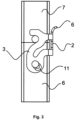
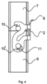
- the Figures 3 and 4 can be seen how the locking receptacles 5, 5 'of the locking bracket 1 engage over the locking pins 9 of the second connector housing 7 in the locked state.
- the first and second connector housings 6, 7 are reversibly locked together.
- a prism-shaped contour 10 is formed on the bearing receptacles 8 and the locking pins 9.
- the locking pin 9 of the second connector housing 7 is in the right part of the contour 10 for a precise representation Figure 2 shown enlarged.
- the contour 10 is prism-shaped and has a triangular cross section along its axis of symmetry.
- the bearing pins 8 and the locking pins 9 are longer than the respective contour 10, 10 '. This means that the bearing pins 8 and the locking pins 9 protrude vertically further from the connector housing than the respective contour 10.
- the locking device 1 has an inwardly directed embossing 11, 11' in the area of the bearing receptacles 4, 4'. With the help of the embossings 11, 11' and the contours 10, 10' formed on the bearing pin 8, the locking device 1 is expanded elastically during the locking process. The locking device 1 does not rub with its side parts 3, 3 'on the connector housings 6, 7. In addition, the respective locking receptacle 5, 5' does not rub on the connector housings 6, 7. Resistance during the final locking is clearly noticeable by the user.
- the locking bracket 1 Due to the shape of the contours 10, 10 'and the associated embossings 11, 11', the locking bracket 1 is held in its position in the closed state. During the unlocking process, resistance must be overcome again because the locking device 1 is expanded elastically again. This prevents the system from being opened accidentally. In addition, the locking device 1 rubs not with their side parts 3, 3 'on the connector housings 6, 7. In addition, the respective locking receptacle 5, 5' does not rub on the connector housings 6, 7.
- the side parts 3, 3 'can have play in the area between the locking receptacle 5, 5' and the associated locking pin 9, so that the locking receptacle 5, 5' does not rub over the surface of the locking pin 9 in the locked state.
Landscapes
- Details Of Connecting Devices For Male And Female Coupling (AREA)
Description
- Die Erfindung bezieht sich auf ein System bestehend aus einem ersten Steckverbindergehäuse und einem zweiten Steckverbindergehäuse und einer Verriegelungsvorrichtung nach der Gattung des unabhängigen Anspruchs 1.
- Derartige Verriegelungsvorrichtungen werden zur reversiblen Verriegelung zweier miteinander gesteckter Steckverbinder bzw. Steckverbindergehäuse eingesetzt.
- Die
DE 29 15 574 A1 zeigt einen Verriegelungsbügel zum reversiblen Verriegeln eines ersten Steckverbindergehäuses mit einem zweiten Steckverbindergehäuse. Der Verriegelungsbügel ist aus einem federelastischen Draht gefertigt. - Die
EP 2 451 021 B1 zeigt eine Verriegelungsvorrichtung für ein Steckverbindersystem. Die Verriegelungseinrichtung umfasst hierbei wenigstens einen Verriegelungsbügel mit zwei im Wesentlichen zueinander parallelen Schenkeln und einem die Schenkel verbindenden Steg, wobei jeder der Schenkel des Verriegelungsbügels zwei Verriegelungsarme umfasst, die Verbindungsabschnitte zur Verbindung mit den starren Befestigungselementen aufweisen. - Die
EP 2 961 005 B1 zeigt einen Steckverbinder, der zur elektrischen Verbindung eines Kraftfahrzeugs mit einem Anhänger dient, mit einem schwenkbaren Verriegelungsbügel, der zwei Bügelschenkel umfasst, die je ein am Steckverbindergehäuse gelagertes Flanschelement und je ein Verriegelungselement aufweisen, das derart ausgestaltet ist, dass es lösbar mit einem an einer dem Steckverbinder korrespondierenden Buchse vorgesehenen Verriegelungswiderlager koppelbar ist. - Die
DE 4 241 256 A1 zeigt einen elektrischen Steckverbinder mit einem verschwenkbaren Bügeln, der in der Verriegelungsstellung an einem Gehäuseteil federnd nachgiebig angeordneter Verriegelungshaken eingreift. - Die
DE 19 830 182 A1 zeigt einen elektrischen Steckverbinder mit einem Verriegelungsbügel, der in Verriegelungsstellung mit der Wirksamkeit eines einarmigen Hebels nach Art eines Vorreibers mit dem Verriegelungsvorsprung des Oberteils zusammenwirkt. - Die
DE 10 2004 061 046 B4 zeigt einen Verriegelungsbügel, der aus einem Blechstück ausgestanzt ist und eine federnde Verriegelung zwischen zwei Steckverbindergehäusen bewirkt. - Beide oben genannten Verriegelungsbügel sind an einem Gehäuse eines Steckverbinders schwenkbar gelagert. Die Verriegelungsbügel weisen eine Arretieraufnahme auf, die über einen Verriegelungszapfen eines zweiten Steckverbindergehäuses greifen, wodurch das erste Steckverbindergehäuse und das zweite Steckverbindergehäuse federnd gegeneinandergepresst werden. Die beiden Steckverbindergehäuse sind dann miteinander verriegelt. Bei dem Verriegelungsvorgang unterliegen die Steckverbindergehäuse und die Verriegelungszapfen einem starken Verschleiß, da die Verriegelungsvorrichtungen beim Schwenkvorgang gegen die Steckverbindergehäuse und insbesondere gegen dessen Lagerzapfen reiben. Bei einer bestimmten Anzahl an Verriegelungszyklen nimmt die Zuverlässigkeit der Verriegelung daher ab.
- Das Deutsche Patent- und Markenamt hat in der Prioritätsanmeldung zu vorliegender Anmeldung den folgenden Stand der Technik recherchiert:
DE 42 41 256 A1 undDE 198 30 182 A1 . - Die Aufgabe der Erfindung besteht darin einen zuverlässigen Verriegelungsbügel vorzuschlagen, der eine verschleißarme Verriegelung zweier Steckverbindergehäuse gewährleistet.
- Die Aufgabe wird durch den Gegenstand des unabhängigen Anspruchs 1 gelöst.
- Vorteilhafte Ausgestaltungen der Erfindung sind in den Unteransprüchen angegeben.
- Die erfindungsgemäße Verriegelungsvorrichtung ist zur Verriegelung zweier Steckverbindergehäuse miteinander vorgesehen. Die Verriegelungsvorrichtung besteht im Wesentlichen aus einer Rückwand und daran angeformten Seitenteilen, wobei der Verriegelungsbügel dabei einen U-förmigen Querschnitt aufweist. Die Seitenteile weisen jeweils eine Lageraufnahme auf. In der Regel ist die Lageraufnahme als kreisrunde Öffnung ausgestaltet. Die Lageraufnahme greift über einen dazu passenden Lagerzapfen eines Steckverbindergehäuses. Durch die Lageraufnahme kann die Verriegelungsvorrichtung schwenkbar an dem Steckverbindergehäuse gelagert werden. Im Bereich der jeweiligen Lageraufnahme weist die Verriegelungsvorrichtung eine zum Steckverbindergehäuse gerichtete Prägung auf.
- Dadurch stützt sich die Verriegelungsvorrichtung nicht gesamtflächig am Steckverbinderkörper ab, wodurch ein verschleißärmerer Verriegelungsvorgang gewährleistet wird.
- Durch die jeweilige Prägung im Bereich der Lageraufnahmen kann die Verriegelungsvorrichtung permanent vom Steckverbindergehäuse beabstandet werden, wodurch weniger Berührkontakt während des Schwenkvorgangs entsteht. Dadurch kann die Verriegelungsvorrichtung leichter bedient werden. Gleichzeitig entsteht weniger Verschleiß am Gehäuse durch Abrieb beim Verriegelungsvorgang.
- Die Verriegelungsvorrichtung besteht aus einer Rückwand mit darin angeformten Seitenteilen. Die Verriegelungsvorrichtung hat einen U-förmigen Querschnitt. Die Seitenteile weisen Lageraufnahmen auf, über die die Verriegelungsvorrichtung an einem ersten Steckverbindergehäuse schwenkbar gelagert ist. Die Seitenteile weisen Arretieraufnahmen auf, die über Arretierzapfen an einem zweiten Steckverbindergehäuse hinübergreifen können.
- Vorzugsweise ist die Verriegelungsvorrichtung als einteiliges Bauteil ausgeführt. Die Verriegelungsvorrichtung ist vorteilhafterweise aus einem elastischen Material gefertigt und kann beispielsweise in einem Stanzbiegeverfahren hergestellt werden. Derartige Herstellungsformen sind besonders preisgünstig.
- Die Verriegelungsvorrichtung wird in der Regel in einem System aus einem ersten Steckverbindergehäuse und einem zweiten Steckverbindergehäuse verwendet. Die Verriegelungsvorrichtung ist dabei schwenkbar über Lagerzapfen am ersten Steckverbindergehäuse befestigt. In einem Schwenkvorgang kann die Verriegelungsvorrichtung über bzw. an Arretierzapfen, die am zweiten Steckverbindergehäuse angeformt sind, hinüber schwenken bzw. befestigt werden. Dadurch können das erste Steckverbindergehäuse und das zweite Steckverbindergehäuse miteinander reversibel verriegelt werden. Der Kern der Erfindung besteht darin, dass die Verriegelungsvorrichtung lediglich im Bereich der Lagerzapfen und der Arretierzapfen mit den jeweiligen Steckverbindergehäusen in Berührkontakt steht. Die Verriegelungsvorrichtung reibt sich nicht am restlichen Gehäusekörper. Dadurch kann ein besonders verschleißarmer Verriegelungsvorgang etabliert werden.
- Vorteilhafterweise bestehen die Steckverbindergehäuse aus Kunststoff. Derartige Steckverbindergehäuse können sehr preisgünstig hergestellt werden. Allerdings sind derartige Steckverbindergehäuse sehr anfällig, wenn sie von metallischen Bauteilen verkratzt werden. Hier wird nicht nur die Ästhetik des Steckverbindergehäuses verändert, sondern auch dessen Funktionalität in Gefahr gebracht.
- Die oben erwähnten Lagerzapfen und/oder die Arretierzapfen weisen eine zylindrische Grundform mit einer daran angeformten prismenförmigen Kontur auf. Dabei hat die prismenförmige Kontur vorzugsweise einen dreieckigen Querschnitt. Eine solche Kontur kann sehr leicht im Herstellungsprozess der Steckverbindergehäuse, vorzugsweise einem Spritzgussprozess, mit vorgesehen werden. Hierdurch entsteht im Herstellungsprozess kein Mehraufwand.
- Die prismenförmige Kontur dient dazu die Verriegelungsvorrichtung am ersten und am zweiten Steckverbindergehäuse im verriegelten Zustand abzustützen. Die Seitenteile der Verriegelungsvorrichtung sind von den Steckverbindergehäusen im Wesentlichen beabstandet. Der Abstand kann von einigen Zehntel Millimeter bis hin zu 3 mm eingestellt werden. Auch die Rückwand steht nicht im Berührkontakt mit den Steckverbindergehäusen.
- Vorzugsweise stehen die Lagerzapfen und die Arretierzapfen und die jeweils daran angeformten Konturen entlang ihrer Symmetrieachse senkrecht vom jeweiligen Steckverbindergehäuse ab. Dabei sind die Lagerzapfen und die Arretierzapfen jeweils länger als die jeweiligen Konturen. Das bedeutet beispielsweise, dass die Arretieraufnahme der Verriegelungsvorrichtung über die Arretierzapfen hinübergreifen kann und von der kürzeren Kontur abgestützt wird. Die Kontur verhindert, dass der Verriegelungsbügel während des Verriegelungsprozesses am Steckverbindergehäuse entlang schleift und während des verriegelten Zustands am Steckverbindergehäuse angelehnt ist.
- Die Verriegelungsvorrichtung weist im Bereich der jeweiligen Lageraufnahme eine zum Steckverbindergehäuse gerichtete Prägung auf. Die Prägung der Verriegelungsvorrichtung stützt sich im verriegelten Zustand auf der Kontur des Lagerzapfens ab. Im unverriegelten Zustand wird die Verriegelungsvorrichtung durch Zusammenspiel von Prägung und Kontur während des Verriegelungsprozesses aufgeweitet. Auch im Entriegelungsvorgang wird die Verriegelungsvorrichtung beim Abschwenken durch die Kontur zunächst aufgeweitet. Der Verriegelungsvorgang und der Entriegelungsvorgang können so jeweils verschleißarm durchgeführt werden.
- Ein Ausführungsbeispiel der Erfindung ist in den Zeichnungen dargestellt und wird im Folgenden näher erläutert. Es zeigen:
- Fig. 1
- eine perspektivische Darstellung einer erfindungsgemäßen Verriegelungsvorrichtung,
- Fig. 2
- eine Seitenansicht eines ersten Steckverbindergehäuses und eines zweiten Steckverbindergehäuses im gesteckten Zustand,
- Fig. 3
- eine Seitenansicht eines ersten Steckverbindergehäuses und eines zweiten Steckverbindergehäuses im gesteckten Zustand mit einem Verriegelungsbügel und
- Fig. 4
- eine Seitenansicht eines ersten Steckverbindergehäuses und eines zweiten Steckverbindergehäuses im gesteckten Zustand mit einem transparenten Verriegelungsbügel.
- Die Figuren enthalten teilweise vereinfachte, schematische Darstellungen. Zum Teil werden für gleiche, aber gegebenenfalls nicht identische Elemente identische Bezugszeichen verwendet. Verschiedene Ansichten gleicher Elemente könnten unterschiedlich skaliert sein.
- Die
Figur 1 zeigt eine perspektivische Darstellung einer erfindungsgemäßen Ausführungsform einer Verriegelungsvorrichtung 1. Die Verriegelungsvorrichtung besteht aus einer Rückwand 2 und zwei daran angeformten Seitenteilen 3, 3'. Die Verriegelungsvorrichtung 1 hat einen im Wesentlichen U-förmigen Querschnitt. In den Seitenteilen 3, 3' ist jeweils im unteren Bereich eine Öffnung eingebracht, die jeweils als Lageraufnahme 4, 4' dienen. Im oberen Bereich weisen die Seitenteile 3, 3' jeweils eine Ausnehmung aus, die jeweils als Arretieraufnahme 5, 5' fungieren. An der Rückwand 2 ist im oberen Bereich ein von der Rückwand 2 zurückgebogenes Betätigungsmittel 6 angeformt. Dieses Betätigungsmittel 6 kann von einem Benutzer zur Kraftaufbringung beim Schwenkvorgang verwendet werden. - In
Figur 2 ist eine Seitenansicht eines ersten Steckverbindergehäuses 6 gesteckt mit einem zweiten Steckverbindergehäuse 7 zu sehen. Die Lageraufnahmen 4, 4' der Verriegelungsvorrichtung 1 können über Lagerzapfen 8 des ersten Steckverbindergehäuse 6 übergreifen. Dadurch ist die Verriegelungsvorrichtung 1 schwenkbar am ersten Steckverbindergehäuse 6 gelagert. An den Schmalseiten des zweiten Steckverbindergehäuses 7 sind Arretierzapfen 9 angeformt. In denFiguren 3 und4 ist zu sehen, wie die Arretieraufnahmen 5, 5' des Verriegelungsbügels 1 im verriegelten Zustand über die Arretierzapfen 9 des zweiten Steckverbindergehäuses 7 übergreifen. Dadurch werden das erste und das zweite Steckverbindergehäuse 6, 7 miteinander reversibel verriegelt. - An den Lageraufnahmen 8 und den Arretierzapfen 9 ist jeweils eine prismenförmigen Kontur 10 angeformt. Der Arretierzapfen 9 des zweiten Steckverbindergehäuses 7 ist zur genauen Darstellung der Kontur 10 im rechten Teil der
Figur 2 vergrößert dargestellt. Die Kontur 10 ist prismenförmig und besitzt einen dreieckigen Querschnitt entlang ihrer Symmetrieachse. Die Lagerzapfen 8 und die Arretierzapfen 9 sind länger ausgeführt als die jeweilige Kontur 10, 10'. Das bedeutet die Lagerzapfen 8 und die Arretierzapfen 9 stehen senkrecht weiter vom Steckverbindergehäuse ab als die jeweilige Kontur 10. - Die Verriegelungsvorrichtung 1 weist im Bereich der Lageraufnahmen 4, 4' jeweils eine nach innen gerichtete Prägung 11, 11' auf. Mithilfe der Prägungen 11, 11`und der an den Lagerzapfen 8 angeformten Konturen 10, 10' wird die Verriegelungsvorrichtung 1 beim Verriegelungsvorgang elastisch geweitet. Die Verriegelungsvorrichtung 1 reibt nicht mit ihren Seitenteilen 3, 3' an den Steckverbindergehäusen 6, 7. Außerdem reibt die jeweilige Arretieraufnahme 5, 5' nicht an den Steckverbindergehäusen 6, 7. Ein Widerstand beim abschließenden Verriegeln ist vom Benutzer deutlich bemerkbar.
- Durch die Form der Konturen 10, 10' und der zugehörigen Prägungen 11, 11' wird der Verriegelungsbügel 1 im verschlossenen Zustand in seiner Lage gehalten. Beim Entriegelungsvorgang muss wieder ein Widerstand überwunden werden, da die Verriegelungsvorrichtung 1 erneut elastisch geweitet wird. Dadurch ist ein versehentliches Öffnen des Systems ausgeschlossen. Außerdem reibt die Verriegelungsvorrichtung 1 nicht mit ihren Seitenteilen 3, 3' an den Steckverbindergehäusen 6, 7. Außerdem reibt die jeweilige Arretieraufnahme 5, 5' nicht an den Steckverbindergehäusen 6, 7.
- Bei der erfindungsgemäßen Verriegelungsvorrichtung 1 können die Seitenteile 3, 3' im Bereich zwischen Arretieraufnahme 5, 5' und den zugehörigen Arretierzapfen 9 Spiel haben, so dass die Arretieraufnahme 5, 5' im verriegelten Zustand nicht über die Oberfläche der Arretierzapfen 9 reibt.
- Auch wenn in den Figuren verschiedene Aspekte oder Merkmale der Erfindung jeweils in Kombination gezeigt sind, ist für den Fachmann - soweit nicht anders angegeben - ersichtlich, dass die dargestellten und diskutieren Kombinationen nicht die einzig möglichen sind. Insbesondere können einander entsprechende Einheiten oder Merkmalskomplexe aus unterschiedlichen Ausführungsbeispielen miteinander ausgetauscht werden.
-
- 1
- Verriegelungsvorrichtung
- 2
- Rückwand
- 3
- Seitenteil
- 4
- Lageraufnahme
- 5
- Arretieraufnahme
- 6
- Erstes Steckverbindergehäuse
- 7
- Zweites Steckverbindergehäuse
- 8
- Lagerzapfen
- 9
- Arretierzapfen
- 10
- Kontur
- 11
- Prägung
Claims (5)
- System bestehend aus einem ersten Steckverbindergehäuse (6) und einem zweiten Steckverbindergehäuse (7) und einer am ersten Steckverbindergehäuse (6) über Lagerzapfen (8) schwenkbar gelagerten Verriegelungsvorrichtung (1), bestehend aus einer Rückwand (2) und daran angeformten Seitenteilen (3, 3'), wobei die Verriegelungsvorrichtung (1) einen U-förmigen Querschnitt aufweist,wobei die Verriegelungsvorrichtung (1) an dem zweiten Steckverbindergehäuse (7) an Arretierzapfen (9) arretierbar ist, wodurch das erste Steckverbindergehäuse (6) und das zweite Steckverbindergehäuse (7) miteinander verriegelt sind,wobei die Lagerzapfen (8) und die Arretierzapfen (9) eine zylindrische Grundform mit einer daran angeformten prismenförmigen Kontur (10, 10') aufweisen,wobei die Seitenteile (3, 3') jeweils eine Lageraufnahme (4, 4') aufweisen, die über die Lagerzapfen (8) des ersten Steckverbindergehäuses (6) greifen, so, dass die Verriegelungsvorrichtung (1) schwenkbar an dem Steckverbindergehäuse (6) gelagert ist,wobei die Verriegelungsvorrichtung (1) im Bereich der jeweiligen Lageraufnahme (4) eine zum ersten Steckverbindergehäuse (6) gerichtete Prägung (11) aufweist, dadurch gekennzeichnet,dass sich die Prägung (11) der Verriegelungsvorrichtung (1) im verriegelten Zustand auf der Kontur (10') des Lagerzapfens (8) so abstützt dass die Verriegelungsvorrichtung (1) lediglich mit den Arretierzapfen (9), den Lagerzapfen (8), und über die Prägung (11) und der prismenförmigen Kontur (10) der Lagerzapfen (8) mit den Steckverbindergehäusen (6, 7) in Berührkontakt steht, und so dass durch die Form der Konturen (10, 10') und der zugehörigen Prägungen (11, 11') die Verriegelungsvorrichtung (1) im verschlossenen Zustand in seiner Lage gehalten wird.
- System nach vorstehendem Anspruch
dadurch gekennzeichnet, dass
die Steckverbindergehäuse (6, 7) aus Kunststoff oder Metall bestehen. - System nach vorstehendem Anspruch
dadurch gekennzeichnet, dass
die prismenförmige Kontur (10) einen dreieckigen Querschnitt aufweist. - System nach Anspruch 1 oder Anspruch 3 dadurch gekennzeichnet,dass die Lagerzapfen (8) und die Arretierzapfen (9) und die jeweils daran angeformte Konturen (10, 10') entlang ihrer Symmetrieachse senkrecht vom Steckverbindergehäuse (6, 7) abstehen unddass die Lagerzapfen (8) und die Arretierzapfen (9) länger sind als die jeweiligen Konturen (10, 10').
- System nach einem der vorstehenden Ansprüche dadurch gekennzeichnet,dass die Verriegelungsvorrichtung (1) Arretieraufnahmen (5) aufweist, die über die Arretierzapfen (9) des zweiten Steckverbindergehäuses (7) greifen,dass sich die Seitenteile (3, 3') der Verriegelungsvorrichtung (1) im verriegelten Zustand jeweils auf der Kontur (10) des Arretierzapfens (9) abstützen.
Applications Claiming Priority (2)
| Application Number | Priority Date | Filing Date | Title |
|---|---|---|---|
| DE102017119057.0A DE102017119057B3 (de) | 2017-08-21 | 2017-08-21 | System aus zwei Steckverbindergehäusen und einer Verriegelungsvorrichtung |
| PCT/DE2018/100692 WO2019037814A1 (de) | 2017-08-21 | 2018-08-07 | Verriegelungsbügel |
Publications (2)
| Publication Number | Publication Date |
|---|---|
| EP3673540A1 EP3673540A1 (de) | 2020-07-01 |
| EP3673540B1 true EP3673540B1 (de) | 2023-10-04 |
Family
ID=63350302
Family Applications (1)
| Application Number | Title | Priority Date | Filing Date |
|---|---|---|---|
| EP18759024.5A Active EP3673540B1 (de) | 2017-08-21 | 2018-08-07 | Steckverbindersystem mit verriegelungsbügel |
Country Status (6)
| Country | Link |
|---|---|
| US (1) | US11095073B2 (de) |
| EP (1) | EP3673540B1 (de) |
| KR (1) | KR102322053B1 (de) |
| CN (1) | CN110998985B (de) |
| DE (1) | DE102017119057B3 (de) |
| WO (1) | WO2019037814A1 (de) |
Families Citing this family (5)
| Publication number | Priority date | Publication date | Assignee | Title |
|---|---|---|---|---|
| DE102020101812A1 (de) * | 2020-01-27 | 2021-07-29 | Harting Electric Gmbh & Co. Kg | Anbaugehäuse |
| DE102020110647A1 (de) | 2020-04-20 | 2021-10-21 | Amphenol Tuchel Industrial GmbH | Primärverriegelung |
| DE202020005530U1 (de) | 2020-04-20 | 2021-07-19 | Amphenol Tuchel Industrial GmbH | Primärverriegelung |
| DE102021128633A1 (de) | 2021-11-03 | 2023-05-04 | Harting Electric Stiftung & Co. Kg | Steckverbindergehäuse mit Verriegelungszapfen |
| DE102021133011B3 (de) | 2021-12-14 | 2023-04-20 | Amphenol Tuchel Industrial GmbH | Verriegelungsvorrichtung für Steckverbindungen sowie Steckverbindung mit einer solchen Verriegelungsvorrichtung |
Citations (1)
| Publication number | Priority date | Publication date | Assignee | Title |
|---|---|---|---|---|
| DE19830182A1 (de) * | 1998-07-06 | 2000-01-20 | Wieland Electric Gmbh | Elektrischer Steckverbinder |
Family Cites Families (17)
| Publication number | Priority date | Publication date | Assignee | Title |
|---|---|---|---|---|
| DE2915574A1 (de) * | 1979-04-18 | 1980-10-23 | Harting Elektronik Gmbh | Gehaeusehaelften-verschluss fuer mehrpolige elektrische steckvorrichtungen |
| DE4241256C2 (de) | 1992-12-08 | 2001-08-16 | Framatome Connectors Int | Elektrischer Steckverbinder |
| US5954528A (en) * | 1996-02-27 | 1999-09-21 | Harness System Technologies Research, Ltd. | Connector connection structure |
| JP3566606B2 (ja) * | 1999-12-10 | 2004-09-15 | 矢崎総業株式会社 | コネクタ支持機構 |
| JP3804558B2 (ja) * | 2002-03-25 | 2006-08-02 | 住友電装株式会社 | レバー式コネクタ |
| ITMI20030136U1 (it) | 2003-03-25 | 2004-09-26 | Ilme Spa | Dispositivo meccanico di chiusura per custodie di connettore elettrico |
| DE102004013476A1 (de) * | 2003-04-16 | 2004-11-04 | Tyco Electronics Amp Gmbh | Steckverbinderanordnung |
| DE102004061046B4 (de) * | 2004-12-18 | 2007-02-08 | Phoenix Contact Gmbh & Co. Kg | Gehäuse-Verschlußvorrichtung |
| US7241155B2 (en) * | 2005-07-28 | 2007-07-10 | Fci Americas Technology, Inc. | Electrical connector assembly with connection assist |
| US7361036B2 (en) * | 2005-10-06 | 2008-04-22 | Fci Americas Technology, Inc. | Electrical connector with lever and latch |
| DE102008019016B4 (de) | 2008-04-15 | 2014-12-18 | Phoenix Contact Gmbh & Co. Kg | Elektrischer Steckverbinder und Verriegelungsbügel zur Verriegelung zweier Gehäuseteile |
| DE102010050567A1 (de) | 2010-11-05 | 2012-05-10 | Lapp Engineering & Co. | Gehäuse für einen Steckverbinder |
| DE102013111760B3 (de) | 2013-10-25 | 2015-04-09 | Harting Electric Gmbh & Co. Kg | Steckverbinder |
| EP2961005B1 (de) | 2014-06-24 | 2019-02-20 | Lapp Engineering & Co. | Steckverbinder und Anschlusskabel |
| EP3012922B8 (de) * | 2014-10-20 | 2017-11-01 | Stäubli Electrical Connectors AG | Schwenkhebelanordnung für Gehäuseanordnung |
| CN104505660A (zh) | 2014-12-22 | 2015-04-08 | 魏德米勒电联接(上海)有限公司 | 一种外壳锁扣装置 |
| CN106911043A (zh) | 2017-03-31 | 2017-06-30 | 沈阳兴华航空电器有限责任公司 | 一种锁紧机构 |
-
2017
- 2017-08-21 DE DE102017119057.0A patent/DE102017119057B3/de active Active
-
2018
- 2018-08-07 CN CN201880054519.4A patent/CN110998985B/zh active Active
- 2018-08-07 EP EP18759024.5A patent/EP3673540B1/de active Active
- 2018-08-07 KR KR1020207008028A patent/KR102322053B1/ko active Active
- 2018-08-07 WO PCT/DE2018/100692 patent/WO2019037814A1/de not_active Ceased
- 2018-08-07 US US16/621,329 patent/US11095073B2/en active Active
Patent Citations (1)
| Publication number | Priority date | Publication date | Assignee | Title |
|---|---|---|---|---|
| DE19830182A1 (de) * | 1998-07-06 | 2000-01-20 | Wieland Electric Gmbh | Elektrischer Steckverbinder |
Also Published As
| Publication number | Publication date |
|---|---|
| CN110998985B (zh) | 2021-07-16 |
| DE102017119057B3 (de) | 2018-11-08 |
| WO2019037814A1 (de) | 2019-02-28 |
| CN110998985A (zh) | 2020-04-10 |
| EP3673540A1 (de) | 2020-07-01 |
| US20200119492A1 (en) | 2020-04-16 |
| KR102322053B1 (ko) | 2021-11-08 |
| KR20200040292A (ko) | 2020-04-17 |
| US11095073B2 (en) | 2021-08-17 |
Similar Documents
| Publication | Publication Date | Title |
|---|---|---|
| EP3673540B1 (de) | Steckverbindersystem mit verriegelungsbügel | |
| EP2133959B1 (de) | Verriegelungsvorrichtung für Steckverbindergehäuse | |
| DE102006041734B4 (de) | Vorrichtung zur Befestigung einer Airbageinheit in einer Baugruppe eines Kraftfahrzeugs, insbesondere in einem Lenkrad, durch Verrasten | |
| DE2905138C2 (de) | ||
| DE2941699A1 (de) | Verbinder zwischen einem wischblatt und einem wischarm | |
| DE102016120929B4 (de) | Verriegelungsbügel für ein Steckverbindergehäuse | |
| EP3707784B1 (de) | Steckverbindergehäuse mit einem schwenkbaren verriegelungsbügel | |
| DE102015106963B4 (de) | Schutzkappe für ein Anbaugehäuse | |
| WO2021104568A1 (de) | Anbaugehäuse für steckverbindungen | |
| WO2019057240A1 (de) | Steckverbindung mit verriegelungsbügel mit sperre sowie verfahren zur verriegelung und entriegelung einer steckverbindung | |
| WO2020244706A1 (de) | Modularer leiterkartensteckverbinder | |
| DE202020106599U1 (de) | Fahrzeugsitzankerbaugruppe | |
| DE202023104776U1 (de) | Verriegelungsbügel für einen Steckverbinder | |
| DE3012939A1 (de) | Gurtschloss fuer einen sicherheitsgurt | |
| EP4115478B1 (de) | Selbstschliessender verriegelungsbügel | |
| DE102005058969B4 (de) | Verriegelungsvorrichtung für Steckerteil und Grundleiste eines elektrischen Steckverbinders | |
| DE4102774C2 (de) | Codierbare elektrische Steckvorrichtung | |
| DE102013001606B4 (de) | Einsatzteil für einen Gurtumlenker sowie Fahrzeugsitz mit integriertem Sicherheitsgurt | |
| EP1345293A2 (de) | Bus-Gehäuse für einen Steckverbinder mit Verriegelungseinrichtung | |
| DE3906421A1 (de) | Verriegelbarer steckverbinder | |
| EP0991146B1 (de) | Elektrischer Steckverbinder | |
| DE60033729T2 (de) | Federklemme mit Positioniervorsprung | |
| DE102018121298A1 (de) | Vorrichtung zum Befestigen eines Anbauteils an einem Trägerbauteil | |
| EP3220489B1 (de) | Elektrische verbindungvorrichtung mit zwei in eingriff bringbaren verbindungsteilen | |
| DE9410996U1 (de) | Steckverbinder mit einem arretierbaren Verriegelungsbügel |
Legal Events
| Date | Code | Title | Description |
|---|---|---|---|
| STAA | Information on the status of an ep patent application or granted ep patent |
Free format text: STATUS: UNKNOWN |
|
| STAA | Information on the status of an ep patent application or granted ep patent |
Free format text: STATUS: THE INTERNATIONAL PUBLICATION HAS BEEN MADE |
|
| PUAI | Public reference made under article 153(3) epc to a published international application that has entered the european phase |
Free format text: ORIGINAL CODE: 0009012 |
|
| STAA | Information on the status of an ep patent application or granted ep patent |
Free format text: STATUS: REQUEST FOR EXAMINATION WAS MADE |
|
| 17P | Request for examination filed |
Effective date: 20200220 |
|
| AK | Designated contracting states |
Kind code of ref document: A1 Designated state(s): AL AT BE BG CH CY CZ DE DK EE ES FI FR GB GR HR HU IE IS IT LI LT LU LV MC MK MT NL NO PL PT RO RS SE SI SK SM TR |
|
| AX | Request for extension of the european patent |
Extension state: BA ME |
|
| DAV | Request for validation of the european patent (deleted) | ||
| DAX | Request for extension of the european patent (deleted) | ||
| STAA | Information on the status of an ep patent application or granted ep patent |
Free format text: STATUS: EXAMINATION IS IN PROGRESS |
|
| 17Q | First examination report despatched |
Effective date: 20211001 |
|
| GRAP | Despatch of communication of intention to grant a patent |
Free format text: ORIGINAL CODE: EPIDOSNIGR1 |
|
| STAA | Information on the status of an ep patent application or granted ep patent |
Free format text: STATUS: GRANT OF PATENT IS INTENDED |
|
| INTG | Intention to grant announced |
Effective date: 20230516 |
|
| GRAS | Grant fee paid |
Free format text: ORIGINAL CODE: EPIDOSNIGR3 |
|
| P01 | Opt-out of the competence of the unified patent court (upc) registered |
Effective date: 20230603 |
|
| GRAA | (expected) grant |
Free format text: ORIGINAL CODE: 0009210 |
|
| STAA | Information on the status of an ep patent application or granted ep patent |
Free format text: STATUS: THE PATENT HAS BEEN GRANTED |
|
| AK | Designated contracting states |
Kind code of ref document: B1 Designated state(s): AL AT BE BG CH CY CZ DE DK EE ES FI FR GB GR HR HU IE IS IT LI LT LU LV MC MK MT NL NO PL PT RO RS SE SI SK SM TR |
|
| REG | Reference to a national code |
Ref country code: GB Ref legal event code: FG4D Free format text: NOT ENGLISH |
|
| REG | Reference to a national code |
Ref country code: CH Ref legal event code: EP |
|
| REG | Reference to a national code |
Ref country code: IE Ref legal event code: FG4D Free format text: LANGUAGE OF EP DOCUMENT: GERMAN |
|
| REG | Reference to a national code |
Ref country code: DE Ref legal event code: R096 Ref document number: 502018013390 Country of ref document: DE |
|
| REG | Reference to a national code |
Ref country code: LT Ref legal event code: MG9D |
|
| REG | Reference to a national code |
Ref country code: NL Ref legal event code: MP Effective date: 20231004 |
|
| PG25 | Lapsed in a contracting state [announced via postgrant information from national office to epo] |
Ref country code: NL Free format text: LAPSE BECAUSE OF FAILURE TO SUBMIT A TRANSLATION OF THE DESCRIPTION OR TO PAY THE FEE WITHIN THE PRESCRIBED TIME-LIMIT Effective date: 20231004 |
|
| PG25 | Lapsed in a contracting state [announced via postgrant information from national office to epo] |
Ref country code: GR Free format text: LAPSE BECAUSE OF FAILURE TO SUBMIT A TRANSLATION OF THE DESCRIPTION OR TO PAY THE FEE WITHIN THE PRESCRIBED TIME-LIMIT Effective date: 20240105 |
|
| PG25 | Lapsed in a contracting state [announced via postgrant information from national office to epo] |
Ref country code: IS Free format text: LAPSE BECAUSE OF FAILURE TO SUBMIT A TRANSLATION OF THE DESCRIPTION OR TO PAY THE FEE WITHIN THE PRESCRIBED TIME-LIMIT Effective date: 20240204 |
|
| PG25 | Lapsed in a contracting state [announced via postgrant information from national office to epo] |
Ref country code: LT Free format text: LAPSE BECAUSE OF FAILURE TO SUBMIT A TRANSLATION OF THE DESCRIPTION OR TO PAY THE FEE WITHIN THE PRESCRIBED TIME-LIMIT Effective date: 20231004 |
|
| PG25 | Lapsed in a contracting state [announced via postgrant information from national office to epo] |
Ref country code: ES Free format text: LAPSE BECAUSE OF FAILURE TO SUBMIT A TRANSLATION OF THE DESCRIPTION OR TO PAY THE FEE WITHIN THE PRESCRIBED TIME-LIMIT Effective date: 20231004 |
|
| PG25 | Lapsed in a contracting state [announced via postgrant information from national office to epo] |
Ref country code: LT Free format text: LAPSE BECAUSE OF FAILURE TO SUBMIT A TRANSLATION OF THE DESCRIPTION OR TO PAY THE FEE WITHIN THE PRESCRIBED TIME-LIMIT Effective date: 20231004 Ref country code: IS Free format text: LAPSE BECAUSE OF FAILURE TO SUBMIT A TRANSLATION OF THE DESCRIPTION OR TO PAY THE FEE WITHIN THE PRESCRIBED TIME-LIMIT Effective date: 20240204 Ref country code: GR Free format text: LAPSE BECAUSE OF FAILURE TO SUBMIT A TRANSLATION OF THE DESCRIPTION OR TO PAY THE FEE WITHIN THE PRESCRIBED TIME-LIMIT Effective date: 20240105 Ref country code: ES Free format text: LAPSE BECAUSE OF FAILURE TO SUBMIT A TRANSLATION OF THE DESCRIPTION OR TO PAY THE FEE WITHIN THE PRESCRIBED TIME-LIMIT Effective date: 20231004 Ref country code: BG Free format text: LAPSE BECAUSE OF FAILURE TO SUBMIT A TRANSLATION OF THE DESCRIPTION OR TO PAY THE FEE WITHIN THE PRESCRIBED TIME-LIMIT Effective date: 20240104 Ref country code: PT Free format text: LAPSE BECAUSE OF FAILURE TO SUBMIT A TRANSLATION OF THE DESCRIPTION OR TO PAY THE FEE WITHIN THE PRESCRIBED TIME-LIMIT Effective date: 20240205 |
|
| PG25 | Lapsed in a contracting state [announced via postgrant information from national office to epo] |
Ref country code: SE Free format text: LAPSE BECAUSE OF FAILURE TO SUBMIT A TRANSLATION OF THE DESCRIPTION OR TO PAY THE FEE WITHIN THE PRESCRIBED TIME-LIMIT Effective date: 20231004 Ref country code: RS Free format text: LAPSE BECAUSE OF FAILURE TO SUBMIT A TRANSLATION OF THE DESCRIPTION OR TO PAY THE FEE WITHIN THE PRESCRIBED TIME-LIMIT Effective date: 20231004 Ref country code: PL Free format text: LAPSE BECAUSE OF FAILURE TO SUBMIT A TRANSLATION OF THE DESCRIPTION OR TO PAY THE FEE WITHIN THE PRESCRIBED TIME-LIMIT Effective date: 20231004 Ref country code: NO Free format text: LAPSE BECAUSE OF FAILURE TO SUBMIT A TRANSLATION OF THE DESCRIPTION OR TO PAY THE FEE WITHIN THE PRESCRIBED TIME-LIMIT Effective date: 20240104 Ref country code: LV Free format text: LAPSE BECAUSE OF FAILURE TO SUBMIT A TRANSLATION OF THE DESCRIPTION OR TO PAY THE FEE WITHIN THE PRESCRIBED TIME-LIMIT Effective date: 20231004 Ref country code: HR Free format text: LAPSE BECAUSE OF FAILURE TO SUBMIT A TRANSLATION OF THE DESCRIPTION OR TO PAY THE FEE WITHIN THE PRESCRIBED TIME-LIMIT Effective date: 20231004 |
|
| REG | Reference to a national code |
Ref country code: DE Ref legal event code: R097 Ref document number: 502018013390 Country of ref document: DE |
|
| PG25 | Lapsed in a contracting state [announced via postgrant information from national office to epo] |
Ref country code: DK Free format text: LAPSE BECAUSE OF FAILURE TO SUBMIT A TRANSLATION OF THE DESCRIPTION OR TO PAY THE FEE WITHIN THE PRESCRIBED TIME-LIMIT Effective date: 20231004 |
|
| PG25 | Lapsed in a contracting state [announced via postgrant information from national office to epo] |
Ref country code: CZ Free format text: LAPSE BECAUSE OF FAILURE TO SUBMIT A TRANSLATION OF THE DESCRIPTION OR TO PAY THE FEE WITHIN THE PRESCRIBED TIME-LIMIT Effective date: 20231004 |
|
| PG25 | Lapsed in a contracting state [announced via postgrant information from national office to epo] |
Ref country code: SK Free format text: LAPSE BECAUSE OF FAILURE TO SUBMIT A TRANSLATION OF THE DESCRIPTION OR TO PAY THE FEE WITHIN THE PRESCRIBED TIME-LIMIT Effective date: 20231004 |
|
| PG25 | Lapsed in a contracting state [announced via postgrant information from national office to epo] |
Ref country code: SM Free format text: LAPSE BECAUSE OF FAILURE TO SUBMIT A TRANSLATION OF THE DESCRIPTION OR TO PAY THE FEE WITHIN THE PRESCRIBED TIME-LIMIT Effective date: 20231004 Ref country code: SK Free format text: LAPSE BECAUSE OF FAILURE TO SUBMIT A TRANSLATION OF THE DESCRIPTION OR TO PAY THE FEE WITHIN THE PRESCRIBED TIME-LIMIT Effective date: 20231004 Ref country code: RO Free format text: LAPSE BECAUSE OF FAILURE TO SUBMIT A TRANSLATION OF THE DESCRIPTION OR TO PAY THE FEE WITHIN THE PRESCRIBED TIME-LIMIT Effective date: 20231004 Ref country code: IT Free format text: LAPSE BECAUSE OF FAILURE TO SUBMIT A TRANSLATION OF THE DESCRIPTION OR TO PAY THE FEE WITHIN THE PRESCRIBED TIME-LIMIT Effective date: 20231004 Ref country code: EE Free format text: LAPSE BECAUSE OF FAILURE TO SUBMIT A TRANSLATION OF THE DESCRIPTION OR TO PAY THE FEE WITHIN THE PRESCRIBED TIME-LIMIT Effective date: 20231004 Ref country code: DK Free format text: LAPSE BECAUSE OF FAILURE TO SUBMIT A TRANSLATION OF THE DESCRIPTION OR TO PAY THE FEE WITHIN THE PRESCRIBED TIME-LIMIT Effective date: 20231004 Ref country code: CZ Free format text: LAPSE BECAUSE OF FAILURE TO SUBMIT A TRANSLATION OF THE DESCRIPTION OR TO PAY THE FEE WITHIN THE PRESCRIBED TIME-LIMIT Effective date: 20231004 |
|
| PLBE | No opposition filed within time limit |
Free format text: ORIGINAL CODE: 0009261 |
|
| STAA | Information on the status of an ep patent application or granted ep patent |
Free format text: STATUS: NO OPPOSITION FILED WITHIN TIME LIMIT |
|
| 26N | No opposition filed |
Effective date: 20240705 |
|
| PG25 | Lapsed in a contracting state [announced via postgrant information from national office to epo] |
Ref country code: SI Free format text: LAPSE BECAUSE OF FAILURE TO SUBMIT A TRANSLATION OF THE DESCRIPTION OR TO PAY THE FEE WITHIN THE PRESCRIBED TIME-LIMIT Effective date: 20231004 |
|
| PG25 | Lapsed in a contracting state [announced via postgrant information from national office to epo] |
Ref country code: SI Free format text: LAPSE BECAUSE OF FAILURE TO SUBMIT A TRANSLATION OF THE DESCRIPTION OR TO PAY THE FEE WITHIN THE PRESCRIBED TIME-LIMIT Effective date: 20231004 |
|
| REG | Reference to a national code |
Ref country code: CH Ref legal event code: PL |
|
| PG25 | Lapsed in a contracting state [announced via postgrant information from national office to epo] |
Ref country code: LU Free format text: LAPSE BECAUSE OF NON-PAYMENT OF DUE FEES Effective date: 20240807 |
|
| PG25 | Lapsed in a contracting state [announced via postgrant information from national office to epo] |
Ref country code: CH Free format text: LAPSE BECAUSE OF NON-PAYMENT OF DUE FEES Effective date: 20240831 Ref country code: MC Free format text: LAPSE BECAUSE OF FAILURE TO SUBMIT A TRANSLATION OF THE DESCRIPTION OR TO PAY THE FEE WITHIN THE PRESCRIBED TIME-LIMIT Effective date: 20231004 |
|
| REG | Reference to a national code |
Ref country code: BE Ref legal event code: MM Effective date: 20240831 |
|
| PG25 | Lapsed in a contracting state [announced via postgrant information from national office to epo] |
Ref country code: BE Free format text: LAPSE BECAUSE OF NON-PAYMENT OF DUE FEES Effective date: 20240831 |
|
| PG25 | Lapsed in a contracting state [announced via postgrant information from national office to epo] |
Ref country code: IE Free format text: LAPSE BECAUSE OF NON-PAYMENT OF DUE FEES Effective date: 20240807 |
|
| PG25 | Lapsed in a contracting state [announced via postgrant information from national office to epo] |
Ref country code: FI Free format text: LAPSE BECAUSE OF FAILURE TO SUBMIT A TRANSLATION OF THE DESCRIPTION OR TO PAY THE FEE WITHIN THE PRESCRIBED TIME-LIMIT Effective date: 20231004 |
|
| PGFP | Annual fee paid to national office [announced via postgrant information from national office to epo] |
Ref country code: DE Payment date: 20250827 Year of fee payment: 8 |
|
| REG | Reference to a national code |
Ref country code: AT Ref legal event code: MM01 Ref document number: 1618730 Country of ref document: AT Kind code of ref document: T Effective date: 20240807 |
|
| PGFP | Annual fee paid to national office [announced via postgrant information from national office to epo] |
Ref country code: GB Payment date: 20250826 Year of fee payment: 8 |
|
| PG25 | Lapsed in a contracting state [announced via postgrant information from national office to epo] |
Ref country code: AT Free format text: LAPSE BECAUSE OF NON-PAYMENT OF DUE FEES Effective date: 20240807 |
|
| PGFP | Annual fee paid to national office [announced via postgrant information from national office to epo] |
Ref country code: FR Payment date: 20250825 Year of fee payment: 8 |
|
| PG25 | Lapsed in a contracting state [announced via postgrant information from national office to epo] |
Ref country code: CY Free format text: LAPSE BECAUSE OF FAILURE TO SUBMIT A TRANSLATION OF THE DESCRIPTION OR TO PAY THE FEE WITHIN THE PRESCRIBED TIME-LIMIT; INVALID AB INITIO Effective date: 20180807 |
|
| PG25 | Lapsed in a contracting state [announced via postgrant information from national office to epo] |
Ref country code: HU Free format text: LAPSE BECAUSE OF FAILURE TO SUBMIT A TRANSLATION OF THE DESCRIPTION OR TO PAY THE FEE WITHIN THE PRESCRIBED TIME-LIMIT; INVALID AB INITIO Effective date: 20180807 |