EP3671968A2 - Elektrisches verbindergehäuse, elektrischer verbinder und elektrische verbinderanordnung - Google Patents
Elektrisches verbindergehäuse, elektrischer verbinder und elektrische verbinderanordnung Download PDFInfo
- Publication number
- EP3671968A2 EP3671968A2 EP19216850.8A EP19216850A EP3671968A2 EP 3671968 A2 EP3671968 A2 EP 3671968A2 EP 19216850 A EP19216850 A EP 19216850A EP 3671968 A2 EP3671968 A2 EP 3671968A2
- Authority
- EP
- European Patent Office
- Prior art keywords
- electrical connector
- movable pin
- receiving portion
- elastic piece
- elastic
- Prior art date
- Legal status (The legal status is an assumption and is not a legal conclusion. Google has not performed a legal analysis and makes no representation as to the accuracy of the status listed.)
- Granted
Links
Images


Classifications
-
- H—ELECTRICITY
- H01—ELECTRIC ELEMENTS
- H01R—ELECTRICALLY-CONDUCTIVE CONNECTIONS; STRUCTURAL ASSOCIATIONS OF A PLURALITY OF MUTUALLY-INSULATED ELECTRICAL CONNECTING ELEMENTS; COUPLING DEVICES; CURRENT COLLECTORS
- H01R13/00—Details of coupling devices of the kinds covered by groups H01R12/70 or H01R24/00 - H01R33/00
- H01R13/02—Contact members
- H01R13/15—Pins, blades or sockets having separate spring member for producing or increasing contact pressure
-
- H—ELECTRICITY
- H01—ELECTRIC ELEMENTS
- H01R—ELECTRICALLY-CONDUCTIVE CONNECTIONS; STRUCTURAL ASSOCIATIONS OF A PLURALITY OF MUTUALLY-INSULATED ELECTRICAL CONNECTING ELEMENTS; COUPLING DEVICES; CURRENT COLLECTORS
- H01R13/00—Details of coupling devices of the kinds covered by groups H01R12/70 or H01R24/00 - H01R33/00
- H01R13/62—Means for facilitating engagement or disengagement of coupling parts or for holding them in engagement
- H01R13/629—Additional means for facilitating engagement or disengagement of coupling parts, e.g. aligning or guiding means, levers, gas pressure electrical locking indicators, manufacturing tolerances
-
- H—ELECTRICITY
- H01—ELECTRIC ELEMENTS
- H01R—ELECTRICALLY-CONDUCTIVE CONNECTIONS; STRUCTURAL ASSOCIATIONS OF A PLURALITY OF MUTUALLY-INSULATED ELECTRICAL CONNECTING ELEMENTS; COUPLING DEVICES; CURRENT COLLECTORS
- H01R12/00—Structural associations of a plurality of mutually-insulated electrical connecting elements, specially adapted for printed circuits, e.g. printed circuit boards [PCB], flat or ribbon cables, or like generally planar structures, e.g. terminal strips, terminal blocks; Coupling devices specially adapted for printed circuits, flat or ribbon cables, or like generally planar structures; Terminals specially adapted for contact with, or insertion into, printed circuits, flat or ribbon cables, or like generally planar structures
- H01R12/70—Coupling devices
- H01R12/71—Coupling devices for rigid printing circuits or like structures
- H01R12/712—Coupling devices for rigid printing circuits or like structures co-operating with the surface of the printed circuit or with a coupling device exclusively provided on the surface of the printed circuit
- H01R12/714—Coupling devices for rigid printing circuits or like structures co-operating with the surface of the printed circuit or with a coupling device exclusively provided on the surface of the printed circuit with contacts abutting directly the printed circuit; Button contacts therefore provided on the printed circuit
-
- H—ELECTRICITY
- H01—ELECTRIC ELEMENTS
- H01R—ELECTRICALLY-CONDUCTIVE CONNECTIONS; STRUCTURAL ASSOCIATIONS OF A PLURALITY OF MUTUALLY-INSULATED ELECTRICAL CONNECTING ELEMENTS; COUPLING DEVICES; CURRENT COLLECTORS
- H01R13/00—Details of coupling devices of the kinds covered by groups H01R12/70 or H01R24/00 - H01R33/00
- H01R13/02—Contact members
- H01R13/15—Pins, blades or sockets having separate spring member for producing or increasing contact pressure
- H01R13/187—Pins, blades or sockets having separate spring member for producing or increasing contact pressure with spring member in the socket
-
- H—ELECTRICITY
- H01—ELECTRIC ELEMENTS
- H01R—ELECTRICALLY-CONDUCTIVE CONNECTIONS; STRUCTURAL ASSOCIATIONS OF A PLURALITY OF MUTUALLY-INSULATED ELECTRICAL CONNECTING ELEMENTS; COUPLING DEVICES; CURRENT COLLECTORS
- H01R13/00—Details of coupling devices of the kinds covered by groups H01R12/70 or H01R24/00 - H01R33/00
- H01R13/02—Contact members
- H01R13/22—Contacts for co-operating by abutting
- H01R13/24—Contacts for co-operating by abutting resilient; resiliently-mounted
- H01R13/2407—Contacts for co-operating by abutting resilient; resiliently-mounted characterized by the resilient means
- H01R13/2421—Contacts for co-operating by abutting resilient; resiliently-mounted characterized by the resilient means using coil springs
-
- H—ELECTRICITY
- H01—ELECTRIC ELEMENTS
- H01R—ELECTRICALLY-CONDUCTIVE CONNECTIONS; STRUCTURAL ASSOCIATIONS OF A PLURALITY OF MUTUALLY-INSULATED ELECTRICAL CONNECTING ELEMENTS; COUPLING DEVICES; CURRENT COLLECTORS
- H01R13/00—Details of coupling devices of the kinds covered by groups H01R12/70 or H01R24/00 - H01R33/00
- H01R13/02—Contact members
- H01R13/22—Contacts for co-operating by abutting
- H01R13/24—Contacts for co-operating by abutting resilient; resiliently-mounted
- H01R13/245—Contacts for co-operating by abutting resilient; resiliently-mounted by stamped-out resilient contact arm
-
- H—ELECTRICITY
- H01—ELECTRIC ELEMENTS
- H01R—ELECTRICALLY-CONDUCTIVE CONNECTIONS; STRUCTURAL ASSOCIATIONS OF A PLURALITY OF MUTUALLY-INSULATED ELECTRICAL CONNECTING ELEMENTS; COUPLING DEVICES; CURRENT COLLECTORS
- H01R13/00—Details of coupling devices of the kinds covered by groups H01R12/70 or H01R24/00 - H01R33/00
- H01R13/40—Securing contact members in or to a base or case; Insulating of contact members
- H01R13/42—Securing in a demountable manner
- H01R13/422—Securing in resilient one-piece base or case, e.g. by friction; One-piece base or case formed with resilient locking means
- H01R13/4223—Securing in resilient one-piece base or case, e.g. by friction; One-piece base or case formed with resilient locking means comprising integral flexible contact retaining fingers
- H01R13/4226—Securing in resilient one-piece base or case, e.g. by friction; One-piece base or case formed with resilient locking means comprising integral flexible contact retaining fingers comprising two or more integral flexible retaining fingers acting on a single contact
-
- H—ELECTRICITY
- H01—ELECTRIC ELEMENTS
- H01R—ELECTRICALLY-CONDUCTIVE CONNECTIONS; STRUCTURAL ASSOCIATIONS OF A PLURALITY OF MUTUALLY-INSULATED ELECTRICAL CONNECTING ELEMENTS; COUPLING DEVICES; CURRENT COLLECTORS
- H01R13/00—Details of coupling devices of the kinds covered by groups H01R12/70 or H01R24/00 - H01R33/00
- H01R13/46—Bases; Cases
-
- H—ELECTRICITY
- H01—ELECTRIC ELEMENTS
- H01R—ELECTRICALLY-CONDUCTIVE CONNECTIONS; STRUCTURAL ASSOCIATIONS OF A PLURALITY OF MUTUALLY-INSULATED ELECTRICAL CONNECTING ELEMENTS; COUPLING DEVICES; CURRENT COLLECTORS
- H01R13/00—Details of coupling devices of the kinds covered by groups H01R12/70 or H01R24/00 - H01R33/00
- H01R13/62—Means for facilitating engagement or disengagement of coupling parts or for holding them in engagement
- H01R13/639—Additional means for holding or locking coupling parts together, after engagement, e.g. separate keylock, retainer strap
-
- H—ELECTRICITY
- H01—ELECTRIC ELEMENTS
- H01R—ELECTRICALLY-CONDUCTIVE CONNECTIONS; STRUCTURAL ASSOCIATIONS OF A PLURALITY OF MUTUALLY-INSULATED ELECTRICAL CONNECTING ELEMENTS; COUPLING DEVICES; CURRENT COLLECTORS
- H01R24/00—Two-part coupling devices, or either of their cooperating parts, characterised by their overall structure
- H01R24/38—Two-part coupling devices, or either of their cooperating parts, characterised by their overall structure having concentrically or coaxially arranged contacts
Definitions
- At least one embodiment of the present disclosure relates to an electrical connector, and more particularly, to an electrical connector housing capable of maintaining stably contact with a movable pin, an electrical connector including the electrical connector housing, and an electrical connector assembly including the electrical connector.
- Some existing electrical connectors generally comprises a structure of a movable pin which is placed in a receiving portion of a cylindrical electrical connector housing, a first end of the movable pin being located in the receiving portion and movably protruding out of the receiving portion against elasticity of a spring so as to be electrically connected to a connection terminal.
- the movable pin is generally kept in contact with the electrical connector housing by a slope at one end thereof.
- Such contact is not stable enough, particularly when there is a vibration or external force applied to the movable pin, which results in poor contact between the movable pin and the electrical connector housing, thereby generating high frequency resonance and current transient interruption.
- An object of the present disclosure is to solve at least one of the above and other problems and defects existing in the prior arts.
- an electrical connector comprising: an electrical connector housing comprising a body in which an receiving portion is formed; at least one movable pin, a part of which is movably located in the receiving portion; a first elastic piece located in the receiving portion, a first end of each movable pin movably protruding out of the receiving portion against elasticity of the first elastic piece; and at least one second elastic piece located between a side wall of the receiving portion and the movable pin and configured to be elastically abutted against an outer circumferential surface of the movable pin.
- the movable pin is adapted to be electrically connected to the electrical connector housing by the first elastic piece and the second elastic piece.
- the second elastic piece is an elastic arm integrally connected to the body.
- each of the elastic arms is formed as an arc-shaped structure protruding from an inner side surface of the electrical connector housing toward the movable pin to be in elastic contact with the movable pin.
- each of the elastic arms extends in an axial direction of the body.
- a plurality of elastic arms are distributed at equal intervals in a circumference direction of the body.
- the second elastic piece is a tube spring provided between a side wall of the electrical connector housing and the movable pin.
- the tube spring comprises at least one elastic sheet each extending axially from two opposite ends of the tube spring toward each other, and being formed as an arc-shaped or a V-shaped structure protruding toward the movable pin.
- the tube spring is provided with an open slot extending axially through the two opposite ends of the tube spring.
- the movable pin is rod-shaped, a second end of the movable pin opposite to the first end being inserted into the receiving portion of the electrical connector housing, and an outer diameter of the first end being smaller than that of the second end.
- the electrical connector further comprises at least one stopping portion engaged with the second end of the movable pin to prevent the movable pin from sliding out of the receiving portion.
- the stopping portion is a stopping elastic sheet integrally connected to the body and protruding radially inward.
- the stopping portion is a recess formed in the body.
- the first end of the receiving portion is provided with a flange protruding radially inward.
- first ends of two movable pins protrude out of opposite first and second ends of the receiving portion, , respectively and the first elastic piece is located between the two movable pins.
- the first end of one movable pin protrudes out of a first end of the receiving portion, and the first elastic piece is located between a second end of the movable pin opposite to the first end and a second end of the receiving portion which is closed and is formed with an extension portion extending away from the first end of the receiving portion.
- the electrical connector housing is formed by stamping.
- an electrical connector housing comprising: a body in which an receiving portion is formed; and at least one elastic arm integrally connected to the body and configured to be elastically abutted against an outer circumferential surface of a movable pin, a part of which is movably located in the receiving portion.
- each of the elastic arms is formed as an arc-shaped structure protruding from an inner side surface of the electrical connector housing toward the movable pin to be in elastic contact with the movable pin.
- each of the elastic arms extends in an axial direction of the body.
- a plurality of elastic arms are distributed at equal intervals in a circumference direction of the body.
- the electrical connector housing further comprises at least one stopping portion adapted to prevent the movable pin from sliding out of the receiving portion.
- the stopping portion is a stopping elastic sheet integrally connected to the body and protruding radially inward.
- the stopping portion is a recess formed in the body.
- the first end of the receiving portion is provided with a flange protruding radially inward.
- opposite first and second ends of the receiving portion are open.
- a first end of the receiving portion is open and a second end of the receiving portion opposite the first end is closed, the second end of the receiving portion being formed with an extension extending portion away from the first end of the receiving portion.
- the electrical connector housing is made by stamping.
- an electrical connector assembly comprising an electrical connector as described above; and a cylinder comprising: an outer conductive cylinder and an inner insulation cylinder provided in the outer conductive cylinder, the electrical connector being provided in the inner insulation cylinder and isolated from the outer conducting cylinder by the inner insulation cylinder.
- the electrical connector housing is provided with a positioning tab engaged with the inner insulation cylinder.
- the electrical connector assembly further comprises a mating connector including an insulation base and a connection terminal connected to the insulation base, the connection terminal extending partially into the outer conductive cylinder and electrically connected to the outer conductive cylinder.
- the electrical connector assembly further comprises a third elastic piece, two opposite ends of the third elastic piece being elastically abutted against the insulation base and the outer conductive barrel, respectively.
- the second elastic piece is provided between the side wall of the receiving portion and the movable pin, and is elastically abutted against the outer circumferential surface of the movable pin, so that the movable pin is electrically connected to the electrical connector housing by the first elastic piece and the second elastic piece, thereby improving the reliability of electrical contact.
- the mobile pin may be kept in electrical contact with the electrical connector housing by the first and the second elastic pieces even in the event of vibration or external force applied to the movable pin, thereby avoiding the occurrence of high frequency resonance and current transient interruption.
- an electrical connector comprising: an electrical connector housing comprising a body in which an receiving portion is formed; at least one movable pin, a part of which is movably located in the receiving portion; a first elastic piece located in the receiving portion, a first end of each movable pin movably protruding out of the receiving portion against elasticity of the first elastic piece; and at least one second elastic piece located between a side wall of the receiving portion and the movable pin and configured to be elastically abutted against an outer circumferential surface of the movable pin.
- the movable pin is adapted to be electrically connected to the electrical connector housing by the first elastic piece and the second elastic piece.
- an electrical connector housing comprising: a body in which an receiving portion is formed; and at least one elastic arm integrally connected to the body and configured to be elastically abutted against an outer circumferential surface of a movable pin, a part of which is movably located in the receiving portion.
- an electrical connector assembly comprising an electrical connector as described above; and a cylinder comprising: an outer conductive cylinder and an inner insulation cylinder provided in the outer conductive cylinder, the electrical connector being provided in the inner insulation cylinder and isolated from the outer conducting cylinder by the inner insulation cylinder.
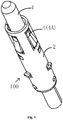
- Fig. 1 is a perspective schematic view illustrating an electrical connector according to an exemplary embodiment of the present disclosure
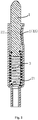
- Fig. 2 is a cross-sectional schematic view illustrating an electrical connector according to an exemplary embodiment of the present disclosure
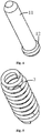
- Fig. 3 is a perspective schematic view illustrating an electrical connector housing according to an exemplary embodiment of the present disclosure
- Fig. 4 is a perspective schematic view illustrating a movable pin according to an exemplary embodiment of the present disclosure
- Fig. 5 is a perspective schematic view illustrating a first elastic piece according to an exemplary embodiment of the present disclosure.
- an electrical connector 100 comprises: a cylindrical electrical connector housing 2 comprising a body 21, one movable pin 1, a first elastic piece 3 and a plurality of second elastic pieces 4.
- a cylindrical receiving portion 22 is formed in the body 21, a part of the movable pin 1 is movably located in the receiving portion 22, and the first elastic piece 3 is located in the receiving portion 22.
- a first end 11 of the movable pin 1 movably protrudes out of the receiving portion 22 against elasticity of the first elastic piece 3.
- the plurality of second elastic pieces 4 are located between a side wall of the receiving portion 22 and the movable pin 1 and are configured to be elastically abutted against an outer circumferential surface of the movable pin 1, so that the movable pin 1 may be electrically connected to the electrical connector housing 2 by the first elastic piece 3 and the second elastic pieces 4.
- the plurality of second elastic pieces 4 comprises a plurality of elastic arms 4A integrally connected to the body 21 and are distributed at intervals in a circumferential direction of the receiving portion 22, so that the movable pin 1 may be kept in electrical contact with the electrical connector housing 2 by the first elastic piece 3 and the second elastic pieces 4 in the event of vibration or external force applied to the movable pin 1.
- each of the elastic arms 4A is formed as an arc-shaped structure protruding from the inner side surface of the electrical connector housing 2 toward the movable pin 1 to be in elastic contact with the movable pin 1, thereby making the movable pin 1 be in reliable electrical contact with the electrical connector housing 2.
- the first end 11 of one movable pin 1 protrudes out of a first end of the receiving portion 22 to be electrically connected to a first electronic component (e.g., a PCB board, not shown), and the first elastic piece 3 is located between a second end 12 of the movable pin 1 opposite to the first end 11 and a second end of the receiving portion 22 which is closed and is formed with an extension portion 27 extending away from the first end of the receiving portion 22 to be electrically connected to a second electronic component (e.g., a PCB board, not shown).
- a first electronic component e.g., a PCB board, not shown
- each of the elastic arms 4A extends in an axial direction of the body 21, thereby facilitating insertion of the movable pin 1 into the receiving portion 22 of the electrical connector housing 2. It is appreciated for those skilled in the art that in other embodiments of the present disclosure, the elastic arm 4A may also extend in a circumferential direction of the body 21, for example.
- the plurality of elastic arms 4A are distributed at regular intervals in the circumferential direction of the body 21, thereby making it easy for the movable pin 1 to be positioned at the center of the receiving portion 22 by the elastic force of the plurality of elastic arms 4A. That is, the axis of the movable pin 1 is coincided with the axis of the receiving portion 22.
- the movable pin 1 is rod-shaped, the first end 11 of the movable pin 1 protruding out of the receiving portion 22 of the electrical connector housing 2, the second end 12 of the movable pin 1 opposite to the first end 11 being inserted into the receiving portion 22 of the electrical connector housing 2, and an outer diameter of the first end 11 being smaller than that of the second end 12. That is, a step is provided between the first end 11 and the second end 12 of the movable pin 1 so that the movable pin 1 is held in the electrical connector housing 2 by the step.
- the electrical connector housing 2 further comprises at least one stopping portion 23 engaged with the second end 12 of the movable pin 1 to prevent the movable pin 1 from sliding out of the receiving portion 22.
- the stopping portion 23 comprises a stopping elastic sheet 23A integrally connected to the body 21 and radially protruding inward.
- a plurality of stopping elastic pieces 23A are distributed at regular intervals in the circumferential direction of the receiving portion 22, and the stopping elastic sheets 23A extend in the axial direction of the body 21.
- a connection between the stopping elastic sheet 23A and the body 21 is close to the first end of the receiving portion 22, and an end of the stopping elastic sheet 23A opposite to the connection with the body 21 is far away from the first end of the receiving portion 22, so that the stopping elastic sheet 23A is deformed by a force of the movable pin 1 to pass the movable pin 1 during the process of inserting the movable pin 1 into the receiving portion 22.
- the stopping elastic sheet 23A is restored by its elastic force, and may be interfered with the step between the first end 11 and the second end 12 of the movable pin 1, thereby preventing the movable pin 1 from slipping out of the receiving portion 22.
- the electrical connector housing 2 is formed as a single conductive member by stamping a single sheet of metal.
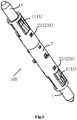
- Fig. 6 is a perspective schematic view illustrating an electrical connector according to another exemplary embodiment of the present disclosure
- Fig. 7 is a cross-sectional schematic view illustrating the electrical connector shown in fig. 6 .
- the electrical connector 100 comprises two movable pins 1, first ends 11 of the two movable pins 1 protruding out of the opposite first and second ends of the receiving portion 22 to be electrically connected to the first electronic component (e.g., a PCB board, not shown) and the second electronic component (e.g., a PCB board, not shown), respectively.
- the first elastic piece 3 is located between the two movable pins 1. That is, two opposite ends of the first elastic piece 3 are elastically abutted against the two movable pins 1, respectively.
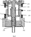
- Fig. 8 is a cross-sectional schematic view illustrating an electrical connector assembly according to an exemplary embodiment of the present disclosure
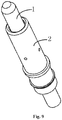
- Fig. 9 is a perspective schematic view illustrating an electrical connector according to another exemplary embodiment of the present disclosure
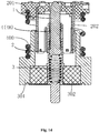
- Fig. 10 is a cross-sectional schematic view illustrating the electrical connector shown in Fig. 9
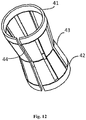
- Fig. 11 is a perspective schematic view illustrating a tube spring according to an exemplary embodiment of the present disclosure
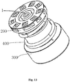
- Fig. 12 is a perspective schematic view illustrating an electrical connector housing according to another exemplary embodiment of the present disclosure.
- the electrical connector housing 2 of the electrical connector 100 comprises a body 21, a movable pin 1, a first elastic piece 3, and a second elastic piece 4.
- a cylindrical receiving portion 22 is formed in the body 21, and a part of the movable pin 1 is movably located in the receiving portion 22.
- the first elastic piece 3 is located in the receiving portion 22, the first end of the movable pin 1 movably protrudes out of the receiving portion 22 against elasticity of the first elastic piece 3.
- the second elastic piece 4 comprises a tube spring 4B provided between the side wall of the electrical connector housing 2 and the movable pin 1 and configured to be elastically abutted against the outer circumferential surface of the movable pin 1 and the side wall of the electrical connector housing 2, so that the movable pin 1 may be electrically connected to the electrical connector housing 2 by the first elastic piece 3 and the second elastic piece 4, respectively.
- the tube spring 4B comprises a plurality of elastic sheets 43 distributed at regular intervals in a circumference direction of the tube spring 4B, each of the elastic sheets 43 axially extending from two opposite ends 41, 42 of the tube spring toward each other and being formed as a V-shaped structure protruding toward the movable pin 1 so as to be elastically abutted against the outer circumferential surface of the movable pin 1.
- the two opposite ends 41, 42 of the tube spring 4B are in electrical contact with the side wall of the electrical connector housing 2, so that the movable pin 1 is electrically connected to the electrical connector housing 2 by the second elastic piece 4.
- the elastic piece 43 may also comprise an arc structure protruding toward the movable pin 1, for example.
- the number of the elastic pieces 43 may be one.
- the tube spring 4B is provided with an open slot 44 extending axially through the ends 41, 42 of the tube spring.
- the range of deformation of the tube spring 4B may be made larger to be applicable to the receiving portions 22 of different sizes (i.e., inner diameters) as much as possible by means of the open groove 44.
- the stopping portion 23 comprise a recess 23B formed in the body 21 and extending in the circumferential direction of the body 21, and the recess 23B may be interfered with the step between the first end 11 and the second end 12 of the movable pin 1, thereby preventing the movable pin 1 from slipping out of the receiving portion 22.
- the first end of the receiving portion 22 is provided with a flange 24 protruding radially inward to prevent impurities such as dust from entering the receiving portion 22, and to prevent the tube spring 4B from slipping out of the receiving portion 22.
- the electrical connector housing 2 is forms as a single conductive member by stamping a single sheet of metal.
- an electrical connector housing 2 comprising: a body 21 in which an receiving portion 22 is formed; and at least one elastic arm 4A integrally connected to the body 21 and configured to be elastically abutted against the outer circumferential surface of the movable pin 1 located in the receiving portion 22.
- the electrical connector assembly comprises the electrical connector 100 as described above any one embodiment and a cylinder 300 comprising an outer conductive cylinder 301 and an inner insulation cylinder 302.
- the inner insulation cylinder 302 is provided within the outer conductive cylinder 301, and the electrical connector 100 is mounted within the inner insulation cylinder 302 and is isolated from the outer conductive cylinder 301 by the inner insulation cylinder 302.
- the electrical connector housing 2 is provided with a positioning tab engaged with the inner insulation cylinder 302, the positioning tab comprising an upper positioning tab 25 engaged with an upper surface of the inner insulation cylinder 302 and a lower positioning tab 26 engaged with a lower surface of the inner insulation cylinder 302, and the electrical connector housing 2 and the inner insulation cylinder 302 are assembled together by the upper and lower positioning tabs.
- the electrical connector assembly further comprises a mating connector 200 including an insulation base 201 and a connection terminal 202 connected to the insulation base 201.
- the connection terminal 202 extends partially into the outer conductive cylinder 301 and is electrically connected to the outer conductive cylinder 301.
- the electrical connector assembly further comprises a third elastic piece 400, such as a spring, two ends of the third elastic piece 400 being elastically abutted against the insulation base 201 and the outer conductive cylinder 301, respectively, such that pressure provided by the third elastic piece 400 ensures that the first electronic component (e.g., a PCB board, not shown) at an upper end is stably and electrically connected with the second electronic component (e.g., a PCB board, not shown) at a lower end of the electrical connector assembly.
- a third elastic piece 400 such as a spring
- the second elastic piece is provided between the side wall of the receiving portion and the movable pin, and is elastically abutted against the outer circumferential surface of the movable pin, so that the movable pin is electrically connected to the electrical connector housing by the first elastic piece and the second elastic piece, respectively, thereby improving the reliability of electrical contact.
- the movable pin may be kept in electrical contact with the electrical connector housing by the first and the second elastic pieces even in the event of vibration or external force applied to the movable pin, thereby avoiding the occurrence of high frequency resonance and current transient interruption.
- the electrical connector assembly may comprise a radio frequency coaxial connector adapted to be electrically connected between the first electronic component and the second electronic component.
Landscapes
- Details Of Connecting Devices For Male And Female Coupling (AREA)
- Connector Housings Or Holding Contact Members (AREA)
Applications Claiming Priority (1)
| Application Number | Priority Date | Filing Date | Title |
|---|---|---|---|
| CN201811578115.3A CN111355076A (zh) | 2018-12-21 | 2018-12-21 | 电连接器壳体、电连接器、电连接器组件 |
Publications (3)
| Publication Number | Publication Date |
|---|---|
| EP3671968A2 true EP3671968A2 (de) | 2020-06-24 |
| EP3671968A3 EP3671968A3 (de) | 2020-09-23 |
| EP3671968B1 EP3671968B1 (de) | 2024-05-01 |
Family
ID=68944138
Family Applications (1)
| Application Number | Title | Priority Date | Filing Date |
|---|---|---|---|
| EP19216850.8A Active EP3671968B1 (de) | 2018-12-21 | 2019-12-17 | Elektrisches verbindergehäuse, elektrischer verbinder und elektrische verbinderanordnung |
Country Status (4)
| Country | Link |
|---|---|
| US (1) | US11355881B2 (de) |
| EP (1) | EP3671968B1 (de) |
| KR (1) | KR102800248B1 (de) |
| CN (1) | CN111355076A (de) |
Families Citing this family (15)
| Publication number | Priority date | Publication date | Assignee | Title |
|---|---|---|---|---|
| USD904314S1 (en) * | 2017-01-30 | 2020-12-08 | Shawn Duggan | Electrical and cabling housing |
| USD851048S1 (en) * | 2017-01-30 | 2019-06-11 | Shawn Duggan | Housing for electrical or cabling wires |
| KR102013690B1 (ko) * | 2018-11-23 | 2019-08-23 | 주식회사 기가레인 | 하우징 일체형 기판 메이팅 커넥터 및 이의 제작 방법 |
| JP7463372B2 (ja) | 2018-11-30 | 2024-04-08 | コーニング オプティカル コミュニケーションズ アールエフ リミテッド ライアビリティ カンパニー | 分岐切込みセクションを備える圧縮性電気接点 |
| TWI884941B (zh) * | 2019-03-11 | 2025-06-01 | 美商山姆科技公司 | 電接觸點、電接觸點陣列、蜂巢式傳輸塔和晶片測試系統 |
| USD936610S1 (en) * | 2019-11-30 | 2021-11-23 | Corning Optical Communications Rf Llc | Compressible electrical contact |
| USD936611S1 (en) * | 2019-11-30 | 2021-11-23 | Corning Optical Communications Rf Llc | Compressible electrical contact |
| WO2021108080A1 (en) | 2019-11-30 | 2021-06-03 | Corning Optical Communications Rf Llc | Connector assemblies |
| JP7455603B2 (ja) * | 2020-02-12 | 2024-03-26 | 株式会社エンプラス | コンタクトピン及びソケット |
| CN113285265B (zh) * | 2020-02-19 | 2023-06-16 | 上海莫仕连接器有限公司 | 电连接器及电连接器组合 |
| US12212083B2 (en) | 2020-11-30 | 2025-01-28 | Corning Optical Communications Rf Llc | Compressible electrical assemblies with divaricated-cut sections |
| CN114914724B (zh) * | 2021-02-09 | 2025-10-03 | 泰科电子(上海)有限公司 | 导电端子、电连接器 |
| JP2023026039A (ja) * | 2021-08-12 | 2023-02-24 | 山一電機株式会社 | プローブ及び検査用ソケット |
| US20230335959A1 (en) * | 2022-04-19 | 2023-10-19 | Itt Manufacturing Enterprises, Llc | Turnable electrical connector and cable assembly |
| CN116466258B (zh) * | 2023-04-21 | 2024-05-17 | 江苏谷英系统工程有限公司 | 一种不间断电源的在线检测系统及预警方法 |
Family Cites Families (30)
| Publication number | Priority date | Publication date | Assignee | Title |
|---|---|---|---|---|
| JP3509038B2 (ja) * | 1994-12-01 | 2004-03-22 | ホシデン株式会社 | スライドピン接点 |
| JP3156957B2 (ja) * | 1995-08-29 | 2001-04-16 | 矢崎総業株式会社 | コネクタ |
| JP2001021615A (ja) * | 1999-07-06 | 2001-01-26 | Yokowo Co Ltd | Bga検査用ソケットのコンタクトプローブ |
| US6814626B2 (en) * | 2002-10-21 | 2004-11-09 | L & K Precision Industry Co., Ltd. | Electrical connector for chargeable battery |
| US6861862B1 (en) * | 2003-03-17 | 2005-03-01 | John O. Tate | Test socket |
| DE20315894U1 (de) | 2003-10-16 | 2003-12-18 | Feinmetall Gmbh | Als Federkontaktstift ausgebildeter Hochstromstift |
| JP4224389B2 (ja) * | 2003-12-16 | 2009-02-12 | 株式会社ヨコオ | スプリングコネクタ |
| DE102004033864A1 (de) * | 2004-07-13 | 2006-02-16 | Era-Contact Gmbh | Elektrischer Druckkontakt |
| US7097460B2 (en) * | 2005-02-01 | 2006-08-29 | Harris Corporation | Coaxial connector |
| ITGE20060052A1 (it) * | 2006-05-05 | 2007-11-06 | Hypertac S P A | Contatto per connessioni elettriche od elettroniche. |
| CN201149917Y (zh) * | 2007-12-14 | 2008-11-12 | 东莞中探探针有限公司 | 弹簧式接触探针 |
| CN201149918Y (zh) * | 2007-12-14 | 2008-11-12 | 东莞中探探针有限公司 | 弹簧式接触探针 |
| CN201336427Y (zh) * | 2008-12-12 | 2009-10-28 | 富港电子(东莞)有限公司 | 探针 |
| CN201352603Y (zh) * | 2008-12-12 | 2009-11-25 | 富港电子(东莞)有限公司 | 探针式连接器 |
| CN201383577Y (zh) * | 2009-03-26 | 2010-01-13 | 长盛科技股份有限公司 | 电池连接器 |
| JP2011096606A (ja) | 2009-11-02 | 2011-05-12 | Smk Corp | ポゴピン式圧接型コネクタ |
| JP2011108445A (ja) * | 2009-11-16 | 2011-06-02 | Hirose Electric Co Ltd | 回路基板用同軸電気コネクタ |
| CN201789125U (zh) * | 2010-08-27 | 2011-04-06 | 富港电子(东莞)有限公司 | 探针 |
| CN202159804U (zh) * | 2010-12-24 | 2012-03-07 | 富港电子(东莞)有限公司 | 探针连接器 |
| CN202025900U (zh) * | 2011-03-25 | 2011-11-02 | 富港电子(东莞)有限公司 | 探针连接器 |
| JP5316821B2 (ja) * | 2011-05-11 | 2013-10-16 | Smk株式会社 | 圧接型コネクタ |
| JP5765674B2 (ja) * | 2012-09-28 | 2015-08-19 | Smk株式会社 | スプリングコネクタとこのスプリングコネクタの組み立て方法 |
| CN203690558U (zh) * | 2013-12-17 | 2014-07-02 | 信连精密工业有限公司 | 探针连接器结构 |
| US9748680B1 (en) * | 2016-06-28 | 2017-08-29 | Intel Corporation | Multiple contact pogo pin |
| CN108346874B (zh) * | 2017-01-24 | 2024-04-02 | 泰科电子(上海)有限公司 | 电连接器 |
| CN206789831U (zh) * | 2017-02-24 | 2017-12-22 | 立讯精密工业股份有限公司 | 射频连接器 |
| CN107359447A (zh) * | 2017-07-11 | 2017-11-17 | 深圳市为致康科技有限公司 | 一种内置冠簧的弹簧顶针及制备方法 |
| JP6909698B2 (ja) * | 2017-10-05 | 2021-07-28 | 株式会社ヨコオ | スプリングコネクタ |
| CN107946813A (zh) * | 2017-11-21 | 2018-04-20 | 东莞市星全工业有限公司 | 弹簧探针 |
| KR101926502B1 (ko) | 2018-03-27 | 2018-12-07 | 주식회사 기가레인 | Pimd 특성이 향상된 신호 컨택부를 포함하는 기판 메이팅 커넥터 |
-
2018
- 2018-12-21 CN CN201811578115.3A patent/CN111355076A/zh active Pending
-
2019
- 2019-12-16 KR KR1020190167422A patent/KR102800248B1/ko active Active
- 2019-12-17 EP EP19216850.8A patent/EP3671968B1/de active Active
- 2019-12-19 US US16/720,263 patent/US11355881B2/en active Active
Also Published As
| Publication number | Publication date |
|---|---|
| KR20200078357A (ko) | 2020-07-01 |
| CN111355076A (zh) | 2020-06-30 |
| EP3671968A3 (de) | 2020-09-23 |
| EP3671968B1 (de) | 2024-05-01 |
| US20200203873A1 (en) | 2020-06-25 |
| US11355881B2 (en) | 2022-06-07 |
| KR102800248B1 (ko) | 2025-04-23 |
Similar Documents
| Publication | Publication Date | Title |
|---|---|---|
| EP3671968A2 (de) | Elektrisches verbindergehäuse, elektrischer verbinder und elektrische verbinderanordnung | |
| US11381012B2 (en) | Electrical connector and electrical connector assembly | |
| US10931051B2 (en) | Connector and receptacle | |
| EP3537546A2 (de) | Verbinder | |
| EP3550669B1 (de) | Koaxial verbinder | |
| US11264753B2 (en) | Connector | |
| CN107154545B (zh) | 具有低轮廓帽的圆形端子 | |
| EP3930114B1 (de) | Durchhangbegrenzender koaxialverbinder | |
| US11404808B2 (en) | Coaxial connector and board-to-board connector assembly | |
| US10707595B2 (en) | Multi-pin connector block assembly | |
| US20210336364A1 (en) | Electrical Terminal, Method for Manufacturing Elastic Terminal, Electrical Connector and Electronic Device | |
| US11196202B2 (en) | Electrical connector and electronic device | |
| CN113783016A (zh) | 一种板间射频连接器 | |
| CN112928515A (zh) | 电连接器和电连接器组件 | |
| CN107565250A (zh) | 连接器 | |
| CN212968376U (zh) | 连接器 | |
| CN211530232U (zh) | 电连接器和电连接器组件 | |
| CN210866559U (zh) | 同轴连接器及板对板连接器组件 | |
| CN210430187U (zh) | 电连接器和电连接器组件 | |
| CN206022693U (zh) | 连接器 | |
| CN210052884U (zh) | 连接器 | |
| CN111916941A (zh) | 连接器 | |
| CN223487401U (zh) | 一种耐压接插装置 | |
| CN110943328B (zh) | 射频连接器 | |
| CN113937580A (zh) | 连接器 |
Legal Events
| Date | Code | Title | Description |
|---|---|---|---|
| PUAI | Public reference made under article 153(3) epc to a published international application that has entered the european phase |
Free format text: ORIGINAL CODE: 0009012 |
|
| STAA | Information on the status of an ep patent application or granted ep patent |
Free format text: STATUS: THE APPLICATION HAS BEEN PUBLISHED |
|
| AK | Designated contracting states |
Kind code of ref document: A2 Designated state(s): AL AT BE BG CH CY CZ DE DK EE ES FI FR GB GR HR HU IE IS IT LI LT LU LV MC MK MT NL NO PL PT RO RS SE SI SK SM TR |
|
| AX | Request for extension of the european patent |
Extension state: BA ME |
|
| PUAL | Search report despatched |
Free format text: ORIGINAL CODE: 0009013 |
|
| AK | Designated contracting states |
Kind code of ref document: A3 Designated state(s): AL AT BE BG CH CY CZ DE DK EE ES FI FR GB GR HR HU IE IS IT LI LT LU LV MC MK MT NL NO PL PT RO RS SE SI SK SM TR |
|
| AX | Request for extension of the european patent |
Extension state: BA ME |
|
| RIC1 | Information provided on ipc code assigned before grant |
Ipc: H01R 24/38 20110101ALI20200819BHEP Ipc: H01R 13/24 20060101AFI20200819BHEP Ipc: H01R 12/71 20110101ALI20200819BHEP Ipc: H01R 13/187 20060101ALI20200819BHEP Ipc: G01R 1/067 20060101ALI20200819BHEP |
|
| STAA | Information on the status of an ep patent application or granted ep patent |
Free format text: STATUS: REQUEST FOR EXAMINATION WAS MADE |
|
| 17P | Request for examination filed |
Effective date: 20210322 |
|
| RBV | Designated contracting states (corrected) |
Designated state(s): AL AT BE BG CH CY CZ DE DK EE ES FI FR GB GR HR HU IE IS IT LI LT LU LV MC MK MT NL NO PL PT RO RS SE SI SK SM TR |
|
| STAA | Information on the status of an ep patent application or granted ep patent |
Free format text: STATUS: EXAMINATION IS IN PROGRESS |
|
| 17Q | First examination report despatched |
Effective date: 20220401 |
|
| GRAJ | Information related to disapproval of communication of intention to grant by the applicant or resumption of examination proceedings by the epo deleted |
Free format text: ORIGINAL CODE: EPIDOSDIGR1 |
|
| GRAP | Despatch of communication of intention to grant a patent |
Free format text: ORIGINAL CODE: EPIDOSNIGR1 |
|
| GRAP | Despatch of communication of intention to grant a patent |
Free format text: ORIGINAL CODE: EPIDOSNIGR1 |
|
| STAA | Information on the status of an ep patent application or granted ep patent |
Free format text: STATUS: GRANT OF PATENT IS INTENDED |
|
| GRAS | Grant fee paid |
Free format text: ORIGINAL CODE: EPIDOSNIGR3 |
|
| INTG | Intention to grant announced |
Effective date: 20240229 |
|
| GRAA | (expected) grant |
Free format text: ORIGINAL CODE: 0009210 |
|
| STAA | Information on the status of an ep patent application or granted ep patent |
Free format text: STATUS: THE PATENT HAS BEEN GRANTED |
|
| P01 | Opt-out of the competence of the unified patent court (upc) registered |
Effective date: 20240320 |
|
| AK | Designated contracting states |
Kind code of ref document: B1 Designated state(s): AL AT BE BG CH CY CZ DE DK EE ES FI FR GB GR HR HU IE IS IT LI LT LU LV MC MK MT NL NO PL PT RO RS SE SI SK SM TR |
|
| REG | Reference to a national code |
Ref country code: GB Ref legal event code: FG4D |
|
| REG | Reference to a national code |
Ref country code: CH Ref legal event code: EP |
|
| REG | Reference to a national code |
Ref country code: IE Ref legal event code: FG4D |
|
| REG | Reference to a national code |
Ref country code: DE Ref legal event code: R096 Ref document number: 602019051290 Country of ref document: DE |
|
| REG | Reference to a national code |
Ref country code: LT Ref legal event code: MG9D |
|
| REG | Reference to a national code |
Ref country code: NL Ref legal event code: MP Effective date: 20240501 |
|
| PG25 | Lapsed in a contracting state [announced via postgrant information from national office to epo] |
Ref country code: IS Free format text: LAPSE BECAUSE OF FAILURE TO SUBMIT A TRANSLATION OF THE DESCRIPTION OR TO PAY THE FEE WITHIN THE PRESCRIBED TIME-LIMIT Effective date: 20240901 |
|
| PG25 | Lapsed in a contracting state [announced via postgrant information from national office to epo] |
Ref country code: BG Free format text: LAPSE BECAUSE OF FAILURE TO SUBMIT A TRANSLATION OF THE DESCRIPTION OR TO PAY THE FEE WITHIN THE PRESCRIBED TIME-LIMIT Effective date: 20240501 |
|
| PG25 | Lapsed in a contracting state [announced via postgrant information from national office to epo] |
Ref country code: HR Free format text: LAPSE BECAUSE OF FAILURE TO SUBMIT A TRANSLATION OF THE DESCRIPTION OR TO PAY THE FEE WITHIN THE PRESCRIBED TIME-LIMIT Effective date: 20240501 Ref country code: FI Free format text: LAPSE BECAUSE OF FAILURE TO SUBMIT A TRANSLATION OF THE DESCRIPTION OR TO PAY THE FEE WITHIN THE PRESCRIBED TIME-LIMIT Effective date: 20240501 |
|
| PG25 | Lapsed in a contracting state [announced via postgrant information from national office to epo] |
Ref country code: GR Free format text: LAPSE BECAUSE OF FAILURE TO SUBMIT A TRANSLATION OF THE DESCRIPTION OR TO PAY THE FEE WITHIN THE PRESCRIBED TIME-LIMIT Effective date: 20240802 |
|
| PG25 | Lapsed in a contracting state [announced via postgrant information from national office to epo] |
Ref country code: PT Free format text: LAPSE BECAUSE OF FAILURE TO SUBMIT A TRANSLATION OF THE DESCRIPTION OR TO PAY THE FEE WITHIN THE PRESCRIBED TIME-LIMIT Effective date: 20240902 |
|
| REG | Reference to a national code |
Ref country code: AT Ref legal event code: MK05 Ref document number: 1683708 Country of ref document: AT Kind code of ref document: T Effective date: 20240501 |
|
| PG25 | Lapsed in a contracting state [announced via postgrant information from national office to epo] |
Ref country code: NL Free format text: LAPSE BECAUSE OF FAILURE TO SUBMIT A TRANSLATION OF THE DESCRIPTION OR TO PAY THE FEE WITHIN THE PRESCRIBED TIME-LIMIT Effective date: 20240501 |
|
| PG25 | Lapsed in a contracting state [announced via postgrant information from national office to epo] |
Ref country code: ES Free format text: LAPSE BECAUSE OF FAILURE TO SUBMIT A TRANSLATION OF THE DESCRIPTION OR TO PAY THE FEE WITHIN THE PRESCRIBED TIME-LIMIT Effective date: 20240501 |
|
| PG25 | Lapsed in a contracting state [announced via postgrant information from national office to epo] |
Ref country code: AT Free format text: LAPSE BECAUSE OF FAILURE TO SUBMIT A TRANSLATION OF THE DESCRIPTION OR TO PAY THE FEE WITHIN THE PRESCRIBED TIME-LIMIT Effective date: 20240501 |
|
| PG25 | Lapsed in a contracting state [announced via postgrant information from national office to epo] |
Ref country code: PL Free format text: LAPSE BECAUSE OF FAILURE TO SUBMIT A TRANSLATION OF THE DESCRIPTION OR TO PAY THE FEE WITHIN THE PRESCRIBED TIME-LIMIT Effective date: 20240501 |
|
| PG25 | Lapsed in a contracting state [announced via postgrant information from national office to epo] |
Ref country code: LV Free format text: LAPSE BECAUSE OF FAILURE TO SUBMIT A TRANSLATION OF THE DESCRIPTION OR TO PAY THE FEE WITHIN THE PRESCRIBED TIME-LIMIT Effective date: 20240501 |
|
| PG25 | Lapsed in a contracting state [announced via postgrant information from national office to epo] |
Ref country code: PT Free format text: LAPSE BECAUSE OF FAILURE TO SUBMIT A TRANSLATION OF THE DESCRIPTION OR TO PAY THE FEE WITHIN THE PRESCRIBED TIME-LIMIT Effective date: 20240902 Ref country code: PL Free format text: LAPSE BECAUSE OF FAILURE TO SUBMIT A TRANSLATION OF THE DESCRIPTION OR TO PAY THE FEE WITHIN THE PRESCRIBED TIME-LIMIT Effective date: 20240501 Ref country code: NO Free format text: LAPSE BECAUSE OF FAILURE TO SUBMIT A TRANSLATION OF THE DESCRIPTION OR TO PAY THE FEE WITHIN THE PRESCRIBED TIME-LIMIT Effective date: 20240801 Ref country code: NL Free format text: LAPSE BECAUSE OF FAILURE TO SUBMIT A TRANSLATION OF THE DESCRIPTION OR TO PAY THE FEE WITHIN THE PRESCRIBED TIME-LIMIT Effective date: 20240501 Ref country code: LV Free format text: LAPSE BECAUSE OF FAILURE TO SUBMIT A TRANSLATION OF THE DESCRIPTION OR TO PAY THE FEE WITHIN THE PRESCRIBED TIME-LIMIT Effective date: 20240501 Ref country code: IS Free format text: LAPSE BECAUSE OF FAILURE TO SUBMIT A TRANSLATION OF THE DESCRIPTION OR TO PAY THE FEE WITHIN THE PRESCRIBED TIME-LIMIT Effective date: 20240901 Ref country code: HR Free format text: LAPSE BECAUSE OF FAILURE TO SUBMIT A TRANSLATION OF THE DESCRIPTION OR TO PAY THE FEE WITHIN THE PRESCRIBED TIME-LIMIT Effective date: 20240501 Ref country code: GR Free format text: LAPSE BECAUSE OF FAILURE TO SUBMIT A TRANSLATION OF THE DESCRIPTION OR TO PAY THE FEE WITHIN THE PRESCRIBED TIME-LIMIT Effective date: 20240802 Ref country code: FI Free format text: LAPSE BECAUSE OF FAILURE TO SUBMIT A TRANSLATION OF THE DESCRIPTION OR TO PAY THE FEE WITHIN THE PRESCRIBED TIME-LIMIT Effective date: 20240501 Ref country code: ES Free format text: LAPSE BECAUSE OF FAILURE TO SUBMIT A TRANSLATION OF THE DESCRIPTION OR TO PAY THE FEE WITHIN THE PRESCRIBED TIME-LIMIT Effective date: 20240501 Ref country code: BG Free format text: LAPSE BECAUSE OF FAILURE TO SUBMIT A TRANSLATION OF THE DESCRIPTION OR TO PAY THE FEE WITHIN THE PRESCRIBED TIME-LIMIT Effective date: 20240501 Ref country code: AT Free format text: LAPSE BECAUSE OF FAILURE TO SUBMIT A TRANSLATION OF THE DESCRIPTION OR TO PAY THE FEE WITHIN THE PRESCRIBED TIME-LIMIT Effective date: 20240501 Ref country code: RS Free format text: LAPSE BECAUSE OF FAILURE TO SUBMIT A TRANSLATION OF THE DESCRIPTION OR TO PAY THE FEE WITHIN THE PRESCRIBED TIME-LIMIT Effective date: 20240801 |
|
| PG25 | Lapsed in a contracting state [announced via postgrant information from national office to epo] |
Ref country code: DK Free format text: LAPSE BECAUSE OF FAILURE TO SUBMIT A TRANSLATION OF THE DESCRIPTION OR TO PAY THE FEE WITHIN THE PRESCRIBED TIME-LIMIT Effective date: 20240501 |
|
| PG25 | Lapsed in a contracting state [announced via postgrant information from national office to epo] |
Ref country code: EE Free format text: LAPSE BECAUSE OF FAILURE TO SUBMIT A TRANSLATION OF THE DESCRIPTION OR TO PAY THE FEE WITHIN THE PRESCRIBED TIME-LIMIT Effective date: 20240501 |
|
| PG25 | Lapsed in a contracting state [announced via postgrant information from national office to epo] |
Ref country code: CZ Free format text: LAPSE BECAUSE OF FAILURE TO SUBMIT A TRANSLATION OF THE DESCRIPTION OR TO PAY THE FEE WITHIN THE PRESCRIBED TIME-LIMIT Effective date: 20240501 |
|
| PG25 | Lapsed in a contracting state [announced via postgrant information from national office to epo] |
Ref country code: RO Free format text: LAPSE BECAUSE OF FAILURE TO SUBMIT A TRANSLATION OF THE DESCRIPTION OR TO PAY THE FEE WITHIN THE PRESCRIBED TIME-LIMIT Effective date: 20240501 Ref country code: SK Free format text: LAPSE BECAUSE OF FAILURE TO SUBMIT A TRANSLATION OF THE DESCRIPTION OR TO PAY THE FEE WITHIN THE PRESCRIBED TIME-LIMIT Effective date: 20240501 |
|
| PG25 | Lapsed in a contracting state [announced via postgrant information from national office to epo] |
Ref country code: SM Free format text: LAPSE BECAUSE OF FAILURE TO SUBMIT A TRANSLATION OF THE DESCRIPTION OR TO PAY THE FEE WITHIN THE PRESCRIBED TIME-LIMIT Effective date: 20240501 |
|
| PG25 | Lapsed in a contracting state [announced via postgrant information from national office to epo] |
Ref country code: SM Free format text: LAPSE BECAUSE OF FAILURE TO SUBMIT A TRANSLATION OF THE DESCRIPTION OR TO PAY THE FEE WITHIN THE PRESCRIBED TIME-LIMIT Effective date: 20240501 Ref country code: SK Free format text: LAPSE BECAUSE OF FAILURE TO SUBMIT A TRANSLATION OF THE DESCRIPTION OR TO PAY THE FEE WITHIN THE PRESCRIBED TIME-LIMIT Effective date: 20240501 Ref country code: RO Free format text: LAPSE BECAUSE OF FAILURE TO SUBMIT A TRANSLATION OF THE DESCRIPTION OR TO PAY THE FEE WITHIN THE PRESCRIBED TIME-LIMIT Effective date: 20240501 Ref country code: EE Free format text: LAPSE BECAUSE OF FAILURE TO SUBMIT A TRANSLATION OF THE DESCRIPTION OR TO PAY THE FEE WITHIN THE PRESCRIBED TIME-LIMIT Effective date: 20240501 Ref country code: DK Free format text: LAPSE BECAUSE OF FAILURE TO SUBMIT A TRANSLATION OF THE DESCRIPTION OR TO PAY THE FEE WITHIN THE PRESCRIBED TIME-LIMIT Effective date: 20240501 Ref country code: CZ Free format text: LAPSE BECAUSE OF FAILURE TO SUBMIT A TRANSLATION OF THE DESCRIPTION OR TO PAY THE FEE WITHIN THE PRESCRIBED TIME-LIMIT Effective date: 20240501 |
|
| REG | Reference to a national code |
Ref country code: DE Ref legal event code: R097 Ref document number: 602019051290 Country of ref document: DE |
|
| PG25 | Lapsed in a contracting state [announced via postgrant information from national office to epo] |
Ref country code: IT Free format text: LAPSE BECAUSE OF FAILURE TO SUBMIT A TRANSLATION OF THE DESCRIPTION OR TO PAY THE FEE WITHIN THE PRESCRIBED TIME-LIMIT Effective date: 20240501 |
|
| PLBE | No opposition filed within time limit |
Free format text: ORIGINAL CODE: 0009261 |
|
| STAA | Information on the status of an ep patent application or granted ep patent |
Free format text: STATUS: NO OPPOSITION FILED WITHIN TIME LIMIT |
|
| 26N | No opposition filed |
Effective date: 20250204 |
|
| PG25 | Lapsed in a contracting state [announced via postgrant information from national office to epo] |
Ref country code: SI Free format text: LAPSE BECAUSE OF FAILURE TO SUBMIT A TRANSLATION OF THE DESCRIPTION OR TO PAY THE FEE WITHIN THE PRESCRIBED TIME-LIMIT Effective date: 20240501 |
|
| PG25 | Lapsed in a contracting state [announced via postgrant information from national office to epo] |
Ref country code: MC Free format text: LAPSE BECAUSE OF FAILURE TO SUBMIT A TRANSLATION OF THE DESCRIPTION OR TO PAY THE FEE WITHIN THE PRESCRIBED TIME-LIMIT Effective date: 20240501 |
|
| REG | Reference to a national code |
Ref country code: CH Ref legal event code: PL |
|
| PG25 | Lapsed in a contracting state [announced via postgrant information from national office to epo] |
Ref country code: LU Free format text: LAPSE BECAUSE OF NON-PAYMENT OF DUE FEES Effective date: 20241217 |
|
| GBPC | Gb: european patent ceased through non-payment of renewal fee |
Effective date: 20241217 |
|
| PG25 | Lapsed in a contracting state [announced via postgrant information from national office to epo] |
Ref country code: SE Free format text: LAPSE BECAUSE OF FAILURE TO SUBMIT A TRANSLATION OF THE DESCRIPTION OR TO PAY THE FEE WITHIN THE PRESCRIBED TIME-LIMIT Effective date: 20240501 |
|
| REG | Reference to a national code |
Ref country code: BE Ref legal event code: MM Effective date: 20241231 |
|
| PG25 | Lapsed in a contracting state [announced via postgrant information from national office to epo] |
Ref country code: GB Free format text: LAPSE BECAUSE OF NON-PAYMENT OF DUE FEES Effective date: 20241217 Ref country code: BE Free format text: LAPSE BECAUSE OF NON-PAYMENT OF DUE FEES Effective date: 20241231 |
|
| PG25 | Lapsed in a contracting state [announced via postgrant information from national office to epo] |
Ref country code: CH Free format text: LAPSE BECAUSE OF NON-PAYMENT OF DUE FEES Effective date: 20241231 |
|
| PG25 | Lapsed in a contracting state [announced via postgrant information from national office to epo] |
Ref country code: IE Free format text: LAPSE BECAUSE OF NON-PAYMENT OF DUE FEES Effective date: 20241217 |
|
| PGFP | Annual fee paid to national office [announced via postgrant information from national office to epo] |
Ref country code: DE Payment date: 20250930 Year of fee payment: 7 |
|
| PGFP | Annual fee paid to national office [announced via postgrant information from national office to epo] |
Ref country code: FR Payment date: 20251008 Year of fee payment: 7 |