EP3669068B1 - Nockenwellenanordnung für einen hubkolbenmotor und verfahren zur umwandlung eines hubkolbenmotors zum laufen in mindestens zwei betriebsarten - Google Patents
Nockenwellenanordnung für einen hubkolbenmotor und verfahren zur umwandlung eines hubkolbenmotors zum laufen in mindestens zwei betriebsarten Download PDFInfo
- Publication number
- EP3669068B1 EP3669068B1 EP17752397.4A EP17752397A EP3669068B1 EP 3669068 B1 EP3669068 B1 EP 3669068B1 EP 17752397 A EP17752397 A EP 17752397A EP 3669068 B1 EP3669068 B1 EP 3669068B1
- Authority
- EP
- European Patent Office
- Prior art keywords
- end part
- camshaft assembly
- intermediate part
- cam
- internal combustion
- Prior art date
- Legal status (The legal status is an assumption and is not a legal conclusion. Google has not performed a legal analysis and makes no representation as to the accuracy of the status listed.)
- Active
Links
- 238000002485 combustion reaction Methods 0.000 title claims description 41
- 238000000034 method Methods 0.000 title claims description 9
- 125000006850 spacer group Chemical group 0.000 claims description 38
- 239000000446 fuel Substances 0.000 claims description 28
- 230000008878 coupling Effects 0.000 claims description 6
- 238000010168 coupling process Methods 0.000 claims description 6
- 238000005859 coupling reaction Methods 0.000 claims description 6
- 239000007788 liquid Substances 0.000 description 8
- 238000006243 chemical reaction Methods 0.000 description 6
- 238000009434 installation Methods 0.000 description 5
- 239000000243 solution Substances 0.000 description 4
- 230000000694 effects Effects 0.000 description 3
- 238000002347 injection Methods 0.000 description 2
- 239000007924 injection Substances 0.000 description 2
- 238000012986 modification Methods 0.000 description 2
- 230000004048 modification Effects 0.000 description 2
- 230000004075 alteration Effects 0.000 description 1
- 230000000712 assembly Effects 0.000 description 1
- 238000000429 assembly Methods 0.000 description 1
- 238000010276 construction Methods 0.000 description 1
- 230000000875 corresponding effect Effects 0.000 description 1
- 230000007812 deficiency Effects 0.000 description 1
- 230000009977 dual effect Effects 0.000 description 1
- 230000013011 mating Effects 0.000 description 1
- 230000035515 penetration Effects 0.000 description 1
Images


Classifications
-
- F—MECHANICAL ENGINEERING; LIGHTING; HEATING; WEAPONS; BLASTING
- F01—MACHINES OR ENGINES IN GENERAL; ENGINE PLANTS IN GENERAL; STEAM ENGINES
- F01L—CYCLICALLY OPERATING VALVES FOR MACHINES OR ENGINES
- F01L1/00—Valve-gear or valve arrangements, e.g. lift-valve gear
- F01L1/02—Valve drive
- F01L1/04—Valve drive by means of cams, camshafts, cam discs, eccentrics or the like
- F01L1/047—Camshafts
-
- F—MECHANICAL ENGINEERING; LIGHTING; HEATING; WEAPONS; BLASTING
- F02—COMBUSTION ENGINES; HOT-GAS OR COMBUSTION-PRODUCT ENGINE PLANTS
- F02M—SUPPLYING COMBUSTION ENGINES IN GENERAL WITH COMBUSTIBLE MIXTURES OR CONSTITUENTS THEREOF
- F02M59/00—Pumps specially adapted for fuel-injection and not provided for in groups F02M39/00 -F02M57/00, e.g. rotary cylinder-block type of pumps
- F02M59/02—Pumps specially adapted for fuel-injection and not provided for in groups F02M39/00 -F02M57/00, e.g. rotary cylinder-block type of pumps of reciprocating-piston or reciprocating-cylinder type
- F02M59/10—Pumps specially adapted for fuel-injection and not provided for in groups F02M39/00 -F02M57/00, e.g. rotary cylinder-block type of pumps of reciprocating-piston or reciprocating-cylinder type characterised by the piston-drive
- F02M59/102—Mechanical drive, e.g. tappets or cams
-
- F—MECHANICAL ENGINEERING; LIGHTING; HEATING; WEAPONS; BLASTING
- F02—COMBUSTION ENGINES; HOT-GAS OR COMBUSTION-PRODUCT ENGINE PLANTS
- F02M—SUPPLYING COMBUSTION ENGINES IN GENERAL WITH COMBUSTIBLE MIXTURES OR CONSTITUENTS THEREOF
- F02M59/00—Pumps specially adapted for fuel-injection and not provided for in groups F02M39/00 -F02M57/00, e.g. rotary cylinder-block type of pumps
- F02M59/44—Details, components parts, or accessories not provided for in, or of interest apart from, the apparatus of groups F02M59/02 - F02M59/42; Pumps having transducers, e.g. to measure displacement of pump rack or piston
-
- F—MECHANICAL ENGINEERING; LIGHTING; HEATING; WEAPONS; BLASTING
- F01—MACHINES OR ENGINES IN GENERAL; ENGINE PLANTS IN GENERAL; STEAM ENGINES
- F01L—CYCLICALLY OPERATING VALVES FOR MACHINES OR ENGINES
- F01L1/00—Valve-gear or valve arrangements, e.g. lift-valve gear
- F01L1/02—Valve drive
- F01L1/04—Valve drive by means of cams, camshafts, cam discs, eccentrics or the like
- F01L1/047—Camshafts
- F01L2001/0471—Assembled camshafts
-
- F—MECHANICAL ENGINEERING; LIGHTING; HEATING; WEAPONS; BLASTING
- F01—MACHINES OR ENGINES IN GENERAL; ENGINE PLANTS IN GENERAL; STEAM ENGINES
- F01L—CYCLICALLY OPERATING VALVES FOR MACHINES OR ENGINES
- F01L2303/00—Manufacturing of components used in valve arrangements
-
- F—MECHANICAL ENGINEERING; LIGHTING; HEATING; WEAPONS; BLASTING
- F02—COMBUSTION ENGINES; HOT-GAS OR COMBUSTION-PRODUCT ENGINE PLANTS
- F02M—SUPPLYING COMBUSTION ENGINES IN GENERAL WITH COMBUSTIBLE MIXTURES OR CONSTITUENTS THEREOF
- F02M2200/00—Details of fuel-injection apparatus, not otherwise provided for
- F02M2200/95—Fuel injection apparatus operating on particular fuels, e.g. biodiesel, ethanol, mixed fuels
Landscapes
- Engineering & Computer Science (AREA)
- Mechanical Engineering (AREA)
- General Engineering & Computer Science (AREA)
- Chemical & Material Sciences (AREA)
- Combustion & Propulsion (AREA)
- Valve-Gear Or Valve Arrangements (AREA)
- Valve Device For Special Equipments (AREA)
Claims (15)
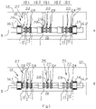
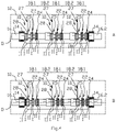
- Nockenwellenanordnung für eine Hubkolbenmotor, die ein erstes Endteil (16.1) und ein zweites Endteil (16.2) und zwischen dem ersten Endteil (16.1) und dem zweiten Endteil (16.2) ein Zwischenteil (18) umfasst, in dem Nocken der Nockenwellenanordnung bereitgestellt sind, wobei die Endteile (16.1, 16.2) mit einer Lageroberfläche derart versehen sind, dass die Nockenwellenanordnung (10) an dem Motor (12) drehbar von Lagern (14) über die Lageroberflächen gestützt zusammengefügt werden kann, und wobei die Nockenwellenanordnung eine Richtung einer Längsachse (D) aufweist, wobei mindestens einer der Nocken des Zwischenteils (18) eine erste Nockenlauffläche (I) und eine zweiten Nockenlauffläche (II) im Wesentlichen nebeneinander in der Richtung der Längsachse (D) umfasst, dadurch gekennzeichnet, dass das Zwischenteil (18) freigebbar mit dem ersten Endteil (16.1) und dem zweiten Endteil (16.2) zusammengefügt ist.
- Nockenwellenanordnung für einen Hubkolbenmotor nach Anspruch 1, dadurch gekennzeichnet, dass die Nockenwellenanordnung Mittel zum Ändern in der Richtung einer Längsachse (D) einer relativen Position des Zwischenteils (18) in Bezug auf die Lageroberfläche des ersten Endteils (16.1) und die Lageroberfläche des zweiten Endteils (16.2) umfasst.
- Nockenwellenanordnung für einen Hubkolbenmotor nach Anspruch 1 oder 2, dadurch gekennzeichnet, dass das Zwischenteil (18) einen ersten Satz von Nocken (22) zur Verwendung beim Betreiben von Ansaugventilen eines Hubkolbenmotors umfasst, und einen zweiten Satz von Nocken (24) zur Verwendung beim Betreiben von Abgasventilen eines Hubkolbenmotors (12) umfasst, und dass jeder der Nocken des ersten Satzes von Nocken (22) und des zweiten Satzes von Nocken (24) eine erste Nockenlauffläche (I) und eine zweite Nockenlauffläche (II) umfasst, die in der Richtung der Längsachse (D) nebeneinander liegen.
- Nockenwellenanordnung für einen Hubkolbenmotor nach Anspruch 1 oder 3, dadurch gekennzeichnet, dass das Zwischenteil (18) einen dritten Satz von Nocken (25) zur Verwendung beim Betreiben einer Kraftstoffpumpe eines Hubkolbenmotors (12) umfasst, und dass jeder der Nocken des dritten Satzes von Nocken nur aus einer ersten Nockenlauffläche (I) besteht.
- Nockenwellenanordnung für einen Hubkolbenmotor nach Anspruch 1 oder 3, dadurch gekennzeichnet, dass das Zwischenteil (18) einen dritten Satz von Nocken (25) zur Verwendung beim Betreiben einer Kraftstoffpumpe eines Hubkolbenmotors (12) umfasst, und dass jeder der Nocken des dritten Satzes von Nocken (25) eine erste Nockenlauffläche (I) und eine zweite Nockenlauffläche (II) umfasst, die in der Richtung der Längsachse (D) nebeneinander liegen.
- Nockenwellenanordnung für einen Hubkolbenmotor nach Anspruch 2, dadurch gekennzeichnet, dass das Mittel zum Ändern der relativen Position des Zwischenteils (18) ein Abstandhalterteil (20) umfasst, das entweder zwischen dem ersten Endteil (16.1) und dem Zwischenteil (18) oder zwischen dem zweiten Endteil (16.2) und dem Zwischenteil (18) zusammengefügt eingerichtet ist.
- Nockenwellenanordnung für einen Hubkolbenmotor nach Anspruch 2, dadurch gekennzeichnet, dass das Zwischenteil (18) freigebbar an dem ersten Endteil (16.1) und an dem zweiten Endteil (16.2) zusammenfügbar ist, und dass die Nockenwellenanordnung (10) ein erstes Abstandhalterteil (20) umfasst, das zwischen dem ersten Endteil (16.1) und dem Zwischenteil (18) zusammengefügt ist.
- Nockenwellenanordnung für einen Hubkolbenmotor nach Anspruch 2, dadurch gekennzeichnet, dass das Zwischenteil (18) freigebbar an dem ersten Endteil (16.1) und an dem zweiten Endteil (16.2) zusammenfügbar ist, und dass die Nockenwellenanordnung (10) ein erstes Abstandhalterteil (20) umfasst, das zwischen dem ersten Endteil (16.1) und dem Zwischenteil (18) zusammengefügt ist, und ein zweites Abstandhalterteil (20), das zwischen dem zweiten Endteil (16.2) und dem Zwischenteil (18) zusammengefügt ist, wobei das erste und das zweite Abstandhalterteil (20) eine unterschiedliche Länge in der Richtung der Längsachse (D) aufweisen, und dass das erste Abstandhalterteil (20) und das zweite Abstandhalterteil (20) miteinander austauschbar sind, um in der Richtung der Längsachse (D) die relative Position des Zwischenteils (18) in Bezug auf die Lageroberfläche des ersten Endteils (16.1) und der Lageroberfläche des zweiten Endteils (16.2) zu ändern.
- Nockenwellenanordnung für einen Hubkolbenmotor nach Anspruch 2, dadurch gekennzeichnet, dass das Mittel zum Ändern der relativen Position des Zwischenteils (18) ein erstes zweites Endteil (16.2a) und ein zweites zweites Endteil (16.2b) umfasst, die mit unterschiedlichen Kopplungslängen der Richtung der Längsachse (D) versehen sind.
- Nockenwellenanordnung für einen Hubkolbenmotor nach Anspruch 2, dadurch gekennzeichnet, dass das Mittel zum Ändern der relativen Position des Zwischenteils (18) ein erstes Endteil (16.1) und ein zweites Endteil (16.2) umfasst, die mit unterschiedlichen Kopplungslängen der Richtung der Längsachse (D) versehen sind, miteinander ersetzbar sind, um in der Richtung der Längsachse (D) zu ändern, wobei das erste Endteil (16.1) und das zweite Endteil (16.2) eine unterschiedliche Länge in der Richtung der Längsachse (D) aufweisen, und wobei das erste Endteil (16.1) und das zweite Endteil (16.2) miteinander austauschbar sind, um in der Richtung der Längsachse (D) die relative Position des Zwischenteils (18) in Bezug auf die Lageroberfläche des ersten Endteils (16.1) und die Lageroberfläche des zweiten Endteils (16.2) zu ändern.
- Nockenwellenanordnung für einen Hubkolbenmotor nach Anspruch 3, dadurch gekennzeichnet, dass das Zwischenteil (18) freigebbar mit dem ersten Endteil (16.1) und mit dem zweiten Endteil (16.2) durch erste Befestigungsmittel zwischen dem ersten Endteil (16.1) und dem Zwischenteil (18) sowie zwischen dem zweiten Endteil (16.2) und dem Zwischenteil (18) zusammenfügbar ist, und dass das Abstandhalterteil (20) mit einem zweiten Befestigungsmittel an seinen beiden Längsenden versehen ist, wobei das zweite Befestigungsmittel (20) zum freigebbaren Zusammenfügen mit mindestens einem des ersten Befestigungsmittels zwischen dem ersten Endteil (16.1) und dem Zwischenteil (18) und des ersten Befestigungsmittels zwischen dem zweiten Endteil (16.2) und dem Zwischenteil (18) kompatibel ist.
- Nockenwellenanordnung für einen Hubkolbenmotor nach Anspruch 3, dadurch gekennzeichnet, dass das Zwischenteil (18) der Nockenwellenanordnung eine Anzahl von Nockenteilen (18.1) umfasst, wobei jeder der Nockenteile (18.1) mindestens einen Nocken umfasst, der zu einem ersten Satz von Nocken (22) gehört, und mindestens einen Nocken, der zu dem zweiten Satz von Nocken (24) gehört, sowie eine Anzahl von Wellenteilen (18.2) zwischen den Nockenteilen (18.1), die freigebbar nacheinander montiert sind, indem sie das Zwischenteil (18) der Nockenwellenanordnung (10) bilden.
- Nockenwellenanordnung für einen Hubkolbenmotor nach Anspruch 3 oder 4, dadurch gekennzeichnet, dass das Zwischenteil (18) der Nockenwellenanordnung (10) eine Anzahl von Nockenteilen (18.1) umfasst, wobei jeder der Nockenteile (18.1) mindestens einen Nocken umfasst, der zu einem ersten Satz von Nocken (22) gehört, und mindestens einen Nocken, der zu dem zweiten Satz von Nocken (24) gehört, und mindestens einen Nocken, der zu dem dritten Satz von Nocken (25) gehört, sowie eine Anzahl von Wellenteilen zwischen den Nockenteilen, die freigebbar nacheinander montiert sind, indem sie das Zwischenteil der Nockenwellenanordnung bilden.
- Nockenwellenanordnung für einen Hubkolbenmotor nach Anspruch 1, dadurch gekennzeichnet, dass die erste Nockenlauffläche (I) und eine zweite Nockenlauffläche unterschiedliche Nockenprofile umfassen.
- Verfahren zum Umwandeln eines Hubkolbenmotors, der die Nockenwellenanordnung nach Anspruch 1 umfasst, um in mindestens zwei Betriebsarten zu laufen, wobei der Motor bei dem Verfahren dazu eingerichtet ist, in einer ersten Betriebsart derart zu laufen, dass das Zwischenteil (18) in die Nockenwellenanordnung zwischen dem ersten Endteil (16.1) und dem zweiten Endteil (16.2) an einer Längsposition derart zusammengefügt ist, dass ein Nockenstößel in dem Motor seine Führung von der ersten Nockenlauffläche (I) bezieht, und der Motor dazu eingerichtet ist, in einer zweiten Betriebsart derart zu laufen, dass das Zwischenteil (18) in die Nockenwellenanordnung an einer Position derart zusammengefügt ist, dass Nockenstößel ihre Führung von der zweiten Nockenlauffläche (II) beziehen.
Applications Claiming Priority (1)
| Application Number | Priority Date | Filing Date | Title |
|---|---|---|---|
| PCT/EP2017/070834 WO2019034254A1 (en) | 2017-08-17 | 2017-08-17 | CAMSHAFT ASSEMBLY FOR INTERNAL COMBUSTION PISTON ENGINE AND METHOD OF CONVERTING INTERNAL COMBUSTION PISTON ENGINE TO PERFORM OPERATION ACCORDING TO AT LEAST TWO OPERATING MODES |
Publications (2)
| Publication Number | Publication Date |
|---|---|
| EP3669068A1 EP3669068A1 (de) | 2020-06-24 |
| EP3669068B1 true EP3669068B1 (de) | 2022-11-23 |
Family
ID=59631784
Family Applications (1)
| Application Number | Title | Priority Date | Filing Date |
|---|---|---|---|
| EP17752397.4A Active EP3669068B1 (de) | 2017-08-17 | 2017-08-17 | Nockenwellenanordnung für einen hubkolbenmotor und verfahren zur umwandlung eines hubkolbenmotors zum laufen in mindestens zwei betriebsarten |
Country Status (4)
| Country | Link |
|---|---|
| EP (1) | EP3669068B1 (de) |
| KR (1) | KR102177594B1 (de) |
| CN (1) | CN111033030B (de) |
| WO (1) | WO2019034254A1 (de) |
Families Citing this family (1)
| Publication number | Priority date | Publication date | Assignee | Title |
|---|---|---|---|---|
| WO2021197563A1 (en) * | 2020-03-30 | 2021-10-07 | Wärtsilä Finland Oy | A camshaft assembly for an internal combustion piston engine and a method of assembling a camshaft assembly into an engine block |
Family Cites Families (16)
| Publication number | Priority date | Publication date | Assignee | Title |
|---|---|---|---|---|
| GB902494A (en) * | 1960-07-22 | 1962-08-01 | Motoren Werke Mannheim Ag | Improvements in or relating to cam-shafts |
| AT364965B (de) * | 1978-12-19 | 1981-11-25 | Steyr Daimler Puch Ag | Nockenwelle fuer einspritzbrennkraftmaschinen |
| US5287840A (en) * | 1992-07-30 | 1994-02-22 | General Electric Canada Inc. | Cam sections for a "V"-type diesel engine |
| DE19611641C1 (de) | 1996-03-25 | 1997-06-05 | Porsche Ag | Ventiltrieb einer Brennkraftmaschine |
| JP3545146B2 (ja) * | 1996-12-04 | 2004-07-21 | ヤンマー株式会社 | 組立式カムシャフトの連結構造 |
| EP1309774B1 (de) * | 2000-08-18 | 2006-11-02 | Jesel, Inc. | Modulare nockenwelle |
| DE10043270A1 (de) * | 2000-09-02 | 2002-03-28 | Man B & W Diesel Ag | Antrieb der Ein- und Auslassventile einer Brennkraftmaschine |
| DE10318008A1 (de) * | 2003-04-19 | 2004-11-18 | Man B & W Diesel Ag | Anordnung zum Steuern der Ein- und Auslasssteuerzeiten von Gaswechselventilen und Kraftstoffeinspritzvorrichtungen einer Brennkraftmaschine |
| DE102004037198A1 (de) | 2004-07-30 | 2006-03-23 | Ina-Schaeffler Kg | Ventiltrieb einer Brennkraftmaschine |
| DE102007010149A1 (de) | 2007-03-02 | 2008-09-04 | Audi Ag | Ventiltrieb für Gaswechselventile einer Brennkraftmaschine mit verschiebbarem Nockenträger und Doppelschneckentrieb |
| DE102007037232A1 (de) | 2007-08-07 | 2009-02-12 | Eto Magnetic Gmbh | Vorrichtung zur Nockenwellenverstellung einer Brennkraftmaschine |
| CN201363169Y (zh) * | 2008-12-30 | 2009-12-16 | 上虞市内燃机配件有限公司 | 嵌套式凸轮轴 |
| CN201963364U (zh) * | 2011-04-02 | 2011-09-07 | 中国石油天然气集团公司 | 发动机通用分段式凸轮轴 |
| CN202832682U (zh) * | 2012-05-22 | 2013-03-27 | 广西玉柴机器股份有限公司 | 柴油机凸轮轴 |
| US8931443B2 (en) * | 2012-12-06 | 2015-01-13 | Ford Global Technologies, Llc | Variable displacement solenoid control |
| KR101427904B1 (ko) * | 2014-07-10 | 2014-08-08 | 주식회사 미보 | 컨센트릭 캠샤프트 및 컨센트릭 캠샤프트의 이동캠 또는 고정캠 제조방법 |
-
2017
- 2017-08-17 KR KR1020207004455A patent/KR102177594B1/ko active IP Right Grant
- 2017-08-17 CN CN201780094003.8A patent/CN111033030B/zh active Active
- 2017-08-17 EP EP17752397.4A patent/EP3669068B1/de active Active
- 2017-08-17 WO PCT/EP2017/070834 patent/WO2019034254A1/en unknown
Also Published As
| Publication number | Publication date |
|---|---|
| WO2019034254A1 (en) | 2019-02-21 |
| CN111033030B (zh) | 2022-03-08 |
| KR102177594B1 (ko) | 2020-11-11 |
| KR20200022039A (ko) | 2020-03-02 |
| EP3669068A1 (de) | 2020-06-24 |
| CN111033030A (zh) | 2020-04-17 |
Similar Documents
| Publication | Publication Date | Title |
|---|---|---|
| RU2560240C2 (ru) | Устройство управления клапаном для двигателя внутреннего сгорания | |
| US10309266B2 (en) | Variable travel valve apparatus for an internal combustion engine | |
| RU2493376C1 (ru) | Устройство регулируемых клапанов для двигателя внутреннего сгорания | |
| US10240525B2 (en) | Variable compression ratio connecting rod system with rotary actuator | |
| CN104662273A (zh) | 用于变化的发动机部件的驱动单元 | |
| RU2500897C2 (ru) | Приводное устройство регулируемых клапанов для двигателя внутреннего сгорания | |
| JP6793079B2 (ja) | 内燃機関用バルブトレイン | |
| US9103240B2 (en) | Camshaft adjuster | |
| US8931442B2 (en) | V-type block of a crank circular slider mechanism and a cylinder liner, a group of the cylinder liner, mechanical equipment thereof | |
| EP3974624A1 (de) | Motornockenwelle und ventiltriebvorrichtung | |
| EP3669068B1 (de) | Nockenwellenanordnung für einen hubkolbenmotor und verfahren zur umwandlung eines hubkolbenmotors zum laufen in mindestens zwei betriebsarten | |
| CN104018905A (zh) | 变冲程发动机液压式配气切换机构 | |
| CN108699924B (zh) | 用于致动内燃发动机中的至少一个气门的装置和内燃发动机 | |
| AU2003269033A1 (en) | Hydraulic valve actuator for reciprocating engine | |
| US20160377030A1 (en) | Internal combustion engine/generator with pressure boost | |
| US9032917B1 (en) | Barrel cam rotating cylinder engine | |
| JPH1163166A (ja) | カムタイミングが内部で可変な複合カム軸 | |
| KR101945279B1 (ko) | 엔진의 캠리스 타입 밸브구동장치 | |
| EP3126643B1 (de) | Gaswechselventilanordnung | |
| WO2021197563A1 (en) | A camshaft assembly for an internal combustion piston engine and a method of assembling a camshaft assembly into an engine block | |
| EP3436676B1 (de) | Leitnockenanordnung für taktmotoren mit differenzial- und variablem hub | |
| WO2019151032A1 (ja) | 燃料ポンプ駆動構造 | |
| US9175581B2 (en) | Externally driven interior axial cam | |
| RU2482300C1 (ru) | Механизм газораспределения фаз роторного двигателя внутреннего сгорания | |
| KR100970051B1 (ko) | 왕복식 엔진용 유압 밸브 액츄에이터 |
Legal Events
| Date | Code | Title | Description |
|---|---|---|---|
| STAA | Information on the status of an ep patent application or granted ep patent |
Free format text: STATUS: UNKNOWN |
|
| STAA | Information on the status of an ep patent application or granted ep patent |
Free format text: STATUS: THE INTERNATIONAL PUBLICATION HAS BEEN MADE |
|
| PUAI | Public reference made under article 153(3) epc to a published international application that has entered the european phase |
Free format text: ORIGINAL CODE: 0009012 |
|
| STAA | Information on the status of an ep patent application or granted ep patent |
Free format text: STATUS: REQUEST FOR EXAMINATION WAS MADE |
|
| 17P | Request for examination filed |
Effective date: 20200221 |
|
| AK | Designated contracting states |
Kind code of ref document: A1 Designated state(s): AL AT BE BG CH CY CZ DE DK EE ES FI FR GB GR HR HU IE IS IT LI LT LU LV MC MK MT NL NO PL PT RO RS SE SI SK SM TR |
|
| AX | Request for extension of the european patent |
Extension state: BA ME |
|
| DAV | Request for validation of the european patent (deleted) | ||
| DAX | Request for extension of the european patent (deleted) | ||
| GRAP | Despatch of communication of intention to grant a patent |
Free format text: ORIGINAL CODE: EPIDOSNIGR1 |
|
| STAA | Information on the status of an ep patent application or granted ep patent |
Free format text: STATUS: GRANT OF PATENT IS INTENDED |
|
| INTG | Intention to grant announced |
Effective date: 20220622 |
|
| GRAS | Grant fee paid |
Free format text: ORIGINAL CODE: EPIDOSNIGR3 |
|
| GRAA | (expected) grant |
Free format text: ORIGINAL CODE: 0009210 |
|
| STAA | Information on the status of an ep patent application or granted ep patent |
Free format text: STATUS: THE PATENT HAS BEEN GRANTED |
|
| AK | Designated contracting states |
Kind code of ref document: B1 Designated state(s): AL AT BE BG CH CY CZ DE DK EE ES FI FR GB GR HR HU IE IS IT LI LT LU LV MC MK MT NL NO PL PT RO RS SE SI SK SM TR |
|
| REG | Reference to a national code |
Ref country code: GB Ref legal event code: FG4D |
|
| REG | Reference to a national code |
Ref country code: CH Ref legal event code: EP |
|
| REG | Reference to a national code |
Ref country code: AT Ref legal event code: REF Ref document number: 1533275 Country of ref document: AT Kind code of ref document: T Effective date: 20221215 Ref country code: DE Ref legal event code: R096 Ref document number: 602017063933 Country of ref document: DE |
|
| REG | Reference to a national code |
Ref country code: IE Ref legal event code: FG4D |
|
| REG | Reference to a national code |
Ref country code: LT Ref legal event code: MG9D |
|
| REG | Reference to a national code |
Ref country code: NL Ref legal event code: MP Effective date: 20221123 |
|
| PG25 | Lapsed in a contracting state [announced via postgrant information from national office to epo] |
Ref country code: SE Free format text: LAPSE BECAUSE OF FAILURE TO SUBMIT A TRANSLATION OF THE DESCRIPTION OR TO PAY THE FEE WITHIN THE PRESCRIBED TIME-LIMIT Effective date: 20221123 Ref country code: PT Free format text: LAPSE BECAUSE OF FAILURE TO SUBMIT A TRANSLATION OF THE DESCRIPTION OR TO PAY THE FEE WITHIN THE PRESCRIBED TIME-LIMIT Effective date: 20230323 Ref country code: NO Free format text: LAPSE BECAUSE OF FAILURE TO SUBMIT A TRANSLATION OF THE DESCRIPTION OR TO PAY THE FEE WITHIN THE PRESCRIBED TIME-LIMIT Effective date: 20230223 Ref country code: LT Free format text: LAPSE BECAUSE OF FAILURE TO SUBMIT A TRANSLATION OF THE DESCRIPTION OR TO PAY THE FEE WITHIN THE PRESCRIBED TIME-LIMIT Effective date: 20221123 Ref country code: FI Free format text: LAPSE BECAUSE OF FAILURE TO SUBMIT A TRANSLATION OF THE DESCRIPTION OR TO PAY THE FEE WITHIN THE PRESCRIBED TIME-LIMIT Effective date: 20221123 Ref country code: ES Free format text: LAPSE BECAUSE OF FAILURE TO SUBMIT A TRANSLATION OF THE DESCRIPTION OR TO PAY THE FEE WITHIN THE PRESCRIBED TIME-LIMIT Effective date: 20221123 |
|
| PG25 | Lapsed in a contracting state [announced via postgrant information from national office to epo] |
Ref country code: RS Free format text: LAPSE BECAUSE OF FAILURE TO SUBMIT A TRANSLATION OF THE DESCRIPTION OR TO PAY THE FEE WITHIN THE PRESCRIBED TIME-LIMIT Effective date: 20221123 Ref country code: PL Free format text: LAPSE BECAUSE OF FAILURE TO SUBMIT A TRANSLATION OF THE DESCRIPTION OR TO PAY THE FEE WITHIN THE PRESCRIBED TIME-LIMIT Effective date: 20221123 Ref country code: LV Free format text: LAPSE BECAUSE OF FAILURE TO SUBMIT A TRANSLATION OF THE DESCRIPTION OR TO PAY THE FEE WITHIN THE PRESCRIBED TIME-LIMIT Effective date: 20221123 Ref country code: IS Free format text: LAPSE BECAUSE OF FAILURE TO SUBMIT A TRANSLATION OF THE DESCRIPTION OR TO PAY THE FEE WITHIN THE PRESCRIBED TIME-LIMIT Effective date: 20230323 Ref country code: HR Free format text: LAPSE BECAUSE OF FAILURE TO SUBMIT A TRANSLATION OF THE DESCRIPTION OR TO PAY THE FEE WITHIN THE PRESCRIBED TIME-LIMIT Effective date: 20221123 Ref country code: GR Free format text: LAPSE BECAUSE OF FAILURE TO SUBMIT A TRANSLATION OF THE DESCRIPTION OR TO PAY THE FEE WITHIN THE PRESCRIBED TIME-LIMIT Effective date: 20230224 |
|
| PG25 | Lapsed in a contracting state [announced via postgrant information from national office to epo] |
Ref country code: NL Free format text: LAPSE BECAUSE OF FAILURE TO SUBMIT A TRANSLATION OF THE DESCRIPTION OR TO PAY THE FEE WITHIN THE PRESCRIBED TIME-LIMIT Effective date: 20221123 |
|
| PG25 | Lapsed in a contracting state [announced via postgrant information from national office to epo] |
Ref country code: SM Free format text: LAPSE BECAUSE OF FAILURE TO SUBMIT A TRANSLATION OF THE DESCRIPTION OR TO PAY THE FEE WITHIN THE PRESCRIBED TIME-LIMIT Effective date: 20221123 Ref country code: RO Free format text: LAPSE BECAUSE OF FAILURE TO SUBMIT A TRANSLATION OF THE DESCRIPTION OR TO PAY THE FEE WITHIN THE PRESCRIBED TIME-LIMIT Effective date: 20221123 Ref country code: EE Free format text: LAPSE BECAUSE OF FAILURE TO SUBMIT A TRANSLATION OF THE DESCRIPTION OR TO PAY THE FEE WITHIN THE PRESCRIBED TIME-LIMIT Effective date: 20221123 Ref country code: DK Free format text: LAPSE BECAUSE OF FAILURE TO SUBMIT A TRANSLATION OF THE DESCRIPTION OR TO PAY THE FEE WITHIN THE PRESCRIBED TIME-LIMIT Effective date: 20221123 Ref country code: CZ Free format text: LAPSE BECAUSE OF FAILURE TO SUBMIT A TRANSLATION OF THE DESCRIPTION OR TO PAY THE FEE WITHIN THE PRESCRIBED TIME-LIMIT Effective date: 20221123 |
|
| REG | Reference to a national code |
Ref country code: DE Ref legal event code: R097 Ref document number: 602017063933 Country of ref document: DE |
|
| PG25 | Lapsed in a contracting state [announced via postgrant information from national office to epo] |
Ref country code: SK Free format text: LAPSE BECAUSE OF FAILURE TO SUBMIT A TRANSLATION OF THE DESCRIPTION OR TO PAY THE FEE WITHIN THE PRESCRIBED TIME-LIMIT Effective date: 20221123 Ref country code: AL Free format text: LAPSE BECAUSE OF FAILURE TO SUBMIT A TRANSLATION OF THE DESCRIPTION OR TO PAY THE FEE WITHIN THE PRESCRIBED TIME-LIMIT Effective date: 20221123 |
|
| PLBE | No opposition filed within time limit |
Free format text: ORIGINAL CODE: 0009261 |
|
| STAA | Information on the status of an ep patent application or granted ep patent |
Free format text: STATUS: NO OPPOSITION FILED WITHIN TIME LIMIT |
|
| PGFP | Annual fee paid to national office [announced via postgrant information from national office to epo] |
Ref country code: AT Payment date: 20230822 Year of fee payment: 7 |
|
| 26N | No opposition filed |
Effective date: 20230824 |
|
| REG | Reference to a national code |
Ref country code: AT Ref legal event code: UEP Ref document number: 1533275 Country of ref document: AT Kind code of ref document: T Effective date: 20221123 |
|
| PG25 | Lapsed in a contracting state [announced via postgrant information from national office to epo] |
Ref country code: SI Free format text: LAPSE BECAUSE OF FAILURE TO SUBMIT A TRANSLATION OF THE DESCRIPTION OR TO PAY THE FEE WITHIN THE PRESCRIBED TIME-LIMIT Effective date: 20221123 |
|
| PGFP | Annual fee paid to national office [announced via postgrant information from national office to epo] |
Ref country code: DE Payment date: 20230821 Year of fee payment: 7 |
|
| PG25 | Lapsed in a contracting state [announced via postgrant information from national office to epo] |
Ref country code: MC Free format text: LAPSE BECAUSE OF FAILURE TO SUBMIT A TRANSLATION OF THE DESCRIPTION OR TO PAY THE FEE WITHIN THE PRESCRIBED TIME-LIMIT Effective date: 20221123 |
|
| REG | Reference to a national code |
Ref country code: CH Ref legal event code: PL |
|
| PG25 | Lapsed in a contracting state [announced via postgrant information from national office to epo] |
Ref country code: MC Free format text: LAPSE BECAUSE OF FAILURE TO SUBMIT A TRANSLATION OF THE DESCRIPTION OR TO PAY THE FEE WITHIN THE PRESCRIBED TIME-LIMIT Effective date: 20221123 |
|
| PG25 | Lapsed in a contracting state [announced via postgrant information from national office to epo] |
Ref country code: LU Free format text: LAPSE BECAUSE OF NON-PAYMENT OF DUE FEES Effective date: 20230817 |
|
| GBPC | Gb: european patent ceased through non-payment of renewal fee |
Effective date: 20230817 |