EP3669068B1 - A camshaft assembly for an internal combustion piston engine and a method of converting an internal combustion piston engine to run in at least two operational modes - Google Patents
A camshaft assembly for an internal combustion piston engine and a method of converting an internal combustion piston engine to run in at least two operational modes Download PDFInfo
- Publication number
- EP3669068B1 EP3669068B1 EP17752397.4A EP17752397A EP3669068B1 EP 3669068 B1 EP3669068 B1 EP 3669068B1 EP 17752397 A EP17752397 A EP 17752397A EP 3669068 B1 EP3669068 B1 EP 3669068B1
- Authority
- EP
- European Patent Office
- Prior art keywords
- end part
- camshaft assembly
- intermediate part
- cam
- internal combustion
- Prior art date
- Legal status (The legal status is an assumption and is not a legal conclusion. Google has not performed a legal analysis and makes no representation as to the accuracy of the status listed.)
- Active
Links
- 238000002485 combustion reaction Methods 0.000 title claims description 41
- 238000000034 method Methods 0.000 title claims description 9
- 125000006850 spacer group Chemical group 0.000 claims description 38
- 239000000446 fuel Substances 0.000 claims description 28
- 230000008878 coupling Effects 0.000 claims description 6
- 238000010168 coupling process Methods 0.000 claims description 6
- 238000005859 coupling reaction Methods 0.000 claims description 6
- 239000007788 liquid Substances 0.000 description 8
- 238000006243 chemical reaction Methods 0.000 description 6
- 238000009434 installation Methods 0.000 description 5
- 239000000243 solution Substances 0.000 description 4
- 230000000694 effects Effects 0.000 description 3
- 238000002347 injection Methods 0.000 description 2
- 239000007924 injection Substances 0.000 description 2
- 238000012986 modification Methods 0.000 description 2
- 230000004048 modification Effects 0.000 description 2
- 230000004075 alteration Effects 0.000 description 1
- 230000000712 assembly Effects 0.000 description 1
- 238000000429 assembly Methods 0.000 description 1
- 238000010276 construction Methods 0.000 description 1
- 230000000875 corresponding effect Effects 0.000 description 1
- 230000007812 deficiency Effects 0.000 description 1
- 230000009977 dual effect Effects 0.000 description 1
- 230000013011 mating Effects 0.000 description 1
- 230000035515 penetration Effects 0.000 description 1
Images


Classifications
-
- F—MECHANICAL ENGINEERING; LIGHTING; HEATING; WEAPONS; BLASTING
- F01—MACHINES OR ENGINES IN GENERAL; ENGINE PLANTS IN GENERAL; STEAM ENGINES
- F01L—CYCLICALLY OPERATING VALVES FOR MACHINES OR ENGINES
- F01L1/00—Valve-gear or valve arrangements, e.g. lift-valve gear
- F01L1/02—Valve drive
- F01L1/04—Valve drive by means of cams, camshafts, cam discs, eccentrics or the like
- F01L1/047—Camshafts
-
- F—MECHANICAL ENGINEERING; LIGHTING; HEATING; WEAPONS; BLASTING
- F02—COMBUSTION ENGINES; HOT-GAS OR COMBUSTION-PRODUCT ENGINE PLANTS
- F02M—SUPPLYING COMBUSTION ENGINES IN GENERAL WITH COMBUSTIBLE MIXTURES OR CONSTITUENTS THEREOF
- F02M59/00—Pumps specially adapted for fuel-injection and not provided for in groups F02M39/00 -F02M57/00, e.g. rotary cylinder-block type of pumps
- F02M59/02—Pumps specially adapted for fuel-injection and not provided for in groups F02M39/00 -F02M57/00, e.g. rotary cylinder-block type of pumps of reciprocating-piston or reciprocating-cylinder type
- F02M59/10—Pumps specially adapted for fuel-injection and not provided for in groups F02M39/00 -F02M57/00, e.g. rotary cylinder-block type of pumps of reciprocating-piston or reciprocating-cylinder type characterised by the piston-drive
- F02M59/102—Mechanical drive, e.g. tappets or cams
-
- F—MECHANICAL ENGINEERING; LIGHTING; HEATING; WEAPONS; BLASTING
- F02—COMBUSTION ENGINES; HOT-GAS OR COMBUSTION-PRODUCT ENGINE PLANTS
- F02M—SUPPLYING COMBUSTION ENGINES IN GENERAL WITH COMBUSTIBLE MIXTURES OR CONSTITUENTS THEREOF
- F02M59/00—Pumps specially adapted for fuel-injection and not provided for in groups F02M39/00 -F02M57/00, e.g. rotary cylinder-block type of pumps
- F02M59/44—Details, components parts, or accessories not provided for in, or of interest apart from, the apparatus of groups F02M59/02 - F02M59/42; Pumps having transducers, e.g. to measure displacement of pump rack or piston
-
- F—MECHANICAL ENGINEERING; LIGHTING; HEATING; WEAPONS; BLASTING
- F01—MACHINES OR ENGINES IN GENERAL; ENGINE PLANTS IN GENERAL; STEAM ENGINES
- F01L—CYCLICALLY OPERATING VALVES FOR MACHINES OR ENGINES
- F01L1/00—Valve-gear or valve arrangements, e.g. lift-valve gear
- F01L1/02—Valve drive
- F01L1/04—Valve drive by means of cams, camshafts, cam discs, eccentrics or the like
- F01L1/047—Camshafts
- F01L2001/0471—Assembled camshafts
-
- F—MECHANICAL ENGINEERING; LIGHTING; HEATING; WEAPONS; BLASTING
- F01—MACHINES OR ENGINES IN GENERAL; ENGINE PLANTS IN GENERAL; STEAM ENGINES
- F01L—CYCLICALLY OPERATING VALVES FOR MACHINES OR ENGINES
- F01L2303/00—Manufacturing of components used in valve arrangements
-
- F—MECHANICAL ENGINEERING; LIGHTING; HEATING; WEAPONS; BLASTING
- F02—COMBUSTION ENGINES; HOT-GAS OR COMBUSTION-PRODUCT ENGINE PLANTS
- F02M—SUPPLYING COMBUSTION ENGINES IN GENERAL WITH COMBUSTIBLE MIXTURES OR CONSTITUENTS THEREOF
- F02M2200/00—Details of fuel-injection apparatus, not otherwise provided for
- F02M2200/95—Fuel injection apparatus operating on particular fuels, e.g. biodiesel, ethanol, mixed fuels
Definitions
- the present invention relates to camshaft assembly for an internal combustion piston engine comprising a first end part and a second end part which are provided with a bearing surface such that the camshaft assembly can be assembled to the engine rotatably supported by the bearings, and between the first end part and the second end part an intermediate part in which cam surfaces of the cam shaft assembly are provided.
- Invention relates also to a method of converting an internal combustion piston engine to run in at least two operational modes.
- pistons are arranged to reciprocate in a cylinder and the reciprocating movement of the pistons is transferred into rotational movement of the crankshaft.
- a camshaft arranged to operate gas exchange valves in each cylinder of the engine.
- a camshaft consist of a cylindrical rod running along the length of the cylinder bank with a number of cams protruding from it. The cams force the valves open by providing pressing force on the valve as the cams rotate.
- a camshaft In large engines, which can provide power e.g. more than 150 kW/cylinder, a camshaft is often constructed from separate parts. Traditionally in the engine conversions between the operating fuels, the cam sections of the shaft have been replaced by fuel-specific cams during conversion. Transportation, storing and mounting heavy cam sections is troublesome and time-consuming. This is also so because the cam surfaces must be handled with care, the handling also causes a risk to the cams to damage when operating in demanding field conditions. Thus, there is a need to develop a more workable solution to the problem.
- An object of the invention is to provide a camshaft assembly, which is simple and reliable to implement and considerably improved compared to the prior art solutions.
- a camshaft assembly for an internal combustion piston engine comprises a first end part and a second end part and between the first end part and the second end part an intermediate part in which cams of the camshaft assembly are provided, which end parts are provided with a bearing surface such that the camshaft assembly can be assembled to the engine rotatably supported by the bearings via the bearing surfaces, and wherein the camshaft assembly has an direction of longitudinal axis , wherein at least one of the cams of the intermediate part comprise a first cam surface and a second cam surface substantially next to each other in the direction of the longitudinal axis, and the intermediate part is releasably assembled to the first end part and to the second end part
- the camshaft assembly comprises means for changing, in the direction of longitudinal axis, a relative position of the intermediate part in respect to the bearing surface of the first end part and the bearing surface of the second end part.
- the intermediate part comprises a first set of cams for use in operating intake valves of an internal combustion piston engine, and second set of cams for use in operating exhaust valves of an internal combustion piston engine, wherein each one of the cams of first set of cams and the second set of cams comprises a first cam surface and a second cam surface being adjacent to each other in the direction of the longitudinal axis.
- the intermediate part comprises a third set of cams for use in operating a fuel pump of an internal combustion piston engine, and each one of the cams of third set of cams consists only a first cam surface.
- the intermediate part comprises a third set of cams for use in operating a fuel pump of an internal combustion piston engine, and that each one of the cams of third set of cams comprises a first cam surface and a second cam surface being adjacent to each other in the direction of the longitudinal axis.
- the means for changing a relative position of the intermediate part comprises at least one spacer part arranged either between the first end part and the intermediate part, or between the second end part and the intermediate part, or more than one spacer part arranged between the first end part and the intermediate part, and between the second end part and the intermediate part, such that the at least one of the first cam surface and a second cam surface of a cam is positioned in the direction of the longitudinal axis at a location of a cam follower, which is the counterpart of the cam surface in the engine.
- the means for changing a relative position of the intermediate part comprises a spacer part arranged assemblable either between the first end part and the intermediate part, or between the second end part and the intermediate part.
- the intermediate part is releasably assemblable to the first end part and to the second end part and that the camshaft assembly comprises a first spacer part assembled between the first end part and the intermediate part,
- the camshaft assembly comprises a first spacer part assembled between the first end part and the intermediate part, and a second spacer part assembled between the second end part and the intermediate part, wherein the first and the second spacer part are of different length in the direction of longitudinal axis, and that the first spacer part and the second spacer part are interchangeable with each other for changing, in the direction of longitudinal axis, the relative position of the intermediate part in respect to the bearing surface of the first end part and the bearing surface of the second end part.
- the means for changing the relative position of the intermediate part comprises a first second end part and a second second end part which are provided with different coupling length s the direction of longitudinal axis.
- the means for changing the relative position of the intermediate part comprises a first end part and a second end part which are provided with different coupling lengths the direction of longitudinal axis, are replaceable with each other for changing, in the direction of longitudinal axis, wherein the first end part and the second end part are of different length in the direction of longitudinal axis, and wherein the first end part and the second end part are interchangeable with each other for changing, in the direction of longitudinal axis, the relative position of the intermediate part in respect to the bearing surface of the first end part and the bearing surface of the second end part.
- the intermediate part is releasably assemblable to the first end part and to the second end part by first attachment means between the first end part and the intermediate part, and between the second end part and the intermediate part.
- the camshaft assembly comprises a spacer part which is provided with a second attachment means at its both longitudinal ends, which second attachment means is compatible for releasable assembly with the first attachment means between the first end part and the intermediate part and with the first attachment means between the second end part and the intermediate part.
- the intermediate part of the camshaft assembly comprises a number of cam sections each one of which comprises first cam surface and a second cam surface and a number of shaft parts between the cam sections releasably mounted one after the other forming the intermediate part of the camshaft assembly.
- the intermediate part of the camshaft assembly comprises a number of cam sections), each one of the cam sections comprising at least one cam belonging to a first set of cams and at least one cam belonging to the second set of cams, and a number of shaft parts between the cam sections releasably mounted one after the other forming the intermediate part of the camshaft assembly.
- the first cam surface and a second cam surface comprise different cam profiles.
- the solution is advantageously usable in an internal combustion piston engine which is convertible between at least two configurations.
- the engine can be converted from diesel engine to gas engine and vice versa, or between gas-fuelled engine with pilot liquid fuel ignition and diesel engine.
- the engine can also be converted to run in a different manners with a same fuel by changing the gas exchange characteristics by changing the gas exchange valves' lifting behaviour.
- cam surface it is meant the guide surface circumscribing the camshaft, against which surface a cam follower runs to get its position guide when in use.
- the camshaft assembly according to the invention provides robust and simple mechanical structure by means of which the conversion can be made in easy manner.
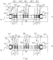
- Figure 1 depicts schematically a camshaft assembly 10 according to an embodiment of the invention.
- Figure 1 shows two different setups of the camshaft assembly 10 in the views A and B into which setups the camshaft assembly 10 is assemblable.
- the camshaft assembly 10 is shown in an installed position in an internal combustion piston engine 12.
- two bearings 14 at end parts of the camshaft assembly 10, via which the camshaft assembly 10 supported in the engine. Even if not shown, it is evident that there may be additional bearings in practise.
- the camshaft assembly 10 comprises a first end part 16.1 and a second end part 16.2 which are provided with a bearing surface such that the camshaft assembly can be assembled to the engine 12 rotatably supported by the bearings 14.
- the position of the first end part 16.1 and the second end part 16.2 is axially determined to the positions of the bearings 14 in the engine 12.
- the first end part 16.1 and the second end part 16.2 can be moved axially to some extent, at least during the conversion is done, such that the camshaft assembly can be disassembled and reassembled to required extent depending on the embodiment of the invention.
- first end part 16.1 and the second end part 16.2 there is an intermediate part 18 assembled.
- intermediate part 18 there are cam surfaces of the cam shaft assembly 10 provided.
- the first end part 16.1, the intermediate part 18 and the second end part 16.2 are arranged successively in the direction of a longitudinal rotation axis D of the camshaft assembly 10.
- the longitudinal rotation axis D is in the direction of a rotational axis of a crank shaft of the engine.
- the intermediate part 18 is releasably assemblable to the first end part 16.1 and the second end part 16.2 by first attachment means between the first end part 16.1 and the intermediate part 18 and between the second end part 16.2 and the intermediate part 18.
- the camshaft assembly 10 comprises a spacer part 20 which is provided with a second attachment means at its both longitudinal ends.
- a spacer part 20 is a straightforward embodiment of the means for changing, in the direction of longitudinal axis D, a relative position of the intermediate part 18 in respect to the bearing surface of the first end part 16.1 and the bearing surface of the second end part 16.2.
- the second attachment means is compatible for installation with the first attachment means between the first end part 16.1 and the intermediate part 18 and with the first attachment means between the second end part 16.2 and the intermediate part 18.
- the second attachment means and the first attachment means are compatible with each other such that the spacer part 20 is selectively installable either between the first end part 16.1 and the intermediate part 18 or between the second end part 16.2 and the intermediate part 18.
- camshaft assembly of the figure 1 it is also conceivable in the spirit of the invention to modify to camshaft assembly of the figure 1 such that there are two separate spacer parts 20, only one of which is suitable for installation in connection with the first end part 16.1 of the camshaft assembly, and only the other one is of which is suitable for installation in connection with the second end part 16.2 of the camshaft assembly.
- one of the spacer parts is provided with the second attachment means compatible with the first attachment means the first end part 16.1 and the other one of the spacer parts is provided with the second attachment means are compatible with the first attachment means the second end part 16.2.
- the view A shows the assembly 10 at its first setup and the in the view B the assembly 10 is shown at its second setup.
- the camshaft assembly 10 provides the effect of shifting the position of the intermediate part 18 in the direction of the longitudinal axis D to the left or right in respect to the bearings 14 in the engine depending on the installation position of the spacer part 20.
- the longitudinal position of the intermediate part 18 of the camshaft assembly 10 is changed, the effective cam surfaces in use are also changed which is explained in the following.
- the intermediate part 18 comprises a first set of cams 22 for use in operating intake valves (not shown) of an internal combustion piston engine, and second set of cams 24 for use in operating exhaust valves (not shown) of an internal combustion piston engine 12.
- Each one of the cams of first set of cams 22 and the second set of cams 24 consists of a first cam surface I and a second cam surface II being adjacent to each other in the direction of the longitudinal axis D.
- the width of the first cam surface I and the second cam surface II is substantially equal to the width of the spacer part 20. What is more important than the width is that the control of the cam follower changes from the first cam surface to the second cam surface, i.e. the intermediate part moves enough, when the setup of the assembly 10 is changed
- the width means a dimension in the direction of the longitudinal axis D.
- the solution is advantageously usable in an internal combustion piston engine which is convertible between at least two operational configurations.
- the engine can be converted from diesel engine to gas engine and vice versa.
- the engine is provided with an actuation system 26 for operating i.e. opening and closing its gas exchange valves (not shown) driven or actuated by the camshaft assembly 10.
- the actuation system 26 comprises a cam follower 28 arranged in connection with each valve actuator.
- the cam follower is configured to follow the cam surface and thus reciprocate according to change of the radial distance of the cam surface from the rotation axis of the camshaft assembly.
- the actuation system belongs to the engine 12 and is arranged to a predetermined, fixed longitudinal position in the direction of the longitudinal axis D in the engine. Therefore, when the camshaft assembly 10 is changed between the setups A and B in respect to the end parts 16.1, 16.2 and the bearings 14, the cam surface effective to the respective cam follower is changed accordingly.
- the intermediate part 18 further comprises a third set of cams 25 for use in operating a liquid fuel pump 27 of an internal combustion piston engine.
- This setup can therefore be used in an engine operating according to diesel cycle using liquid fuel.
- the fuel pump is provided with a cam follower 28.
- each one of the cams of third set of cams 25 has only a first cam surface I.
- the first cam surface is intended for use when the engine is configured to operate according to diesel cycle and when the camshaft has been modified such that no cam surface is at the location of the fuel pump 27 the engine can be operated as for example spark ignited gas engine.
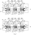
- the intermediate part 18 comprises a number of cam sections 18.1 being equal to the number of cylinders of the engine 12.
- Each one of the cam sections 18.1 comprises at least one cam belonging to the first set of cams 22 and at least one cam belonging to the second set of cams 24 as is shown in the embodiment of figure 2 .
- the camshaft assembly according to the embodiment of the figure 2 is usable for cases where different gas exchange behaviour is desired to be obtained. Otherwise the camshaft assembly 10 shown in the figure 2 corresponds to that shown in the figure 1 .
- the cam section 18.1 comprises also one cam belonging to the third set of the cams 25 intended for operate eg. a fuel pump.
- the intermediate part 18 comprises also a number of shaft parts 18.2 between the cam sections 18.1 releasably mounted one after the other forming the intermediate part 18 of the camshaft assembly 10.
- the shaft part 18.2 is advantageously provided with a bearing surface to make it possible to support the cam shaft assembly 10 rotatably in respect to its longitudinal axis, between the end parts thereof, by means of the shaft parts 18.2.
- the number of cams may vary according to the design of the engine, i.e. according to the actual number of gas exchange valves in one cylinder and number of other camshaft operated devices.
- the first cam surface I and a second cam surface II comprise different cam profiles for use at different configurations of the engine and the selection of the used cam surface is employed by alternatively selecting and assembling the first or the second setup of the camshaft assembly 10.
- the change of the setup is done while the engine is stopped.
- a cam shaft assembly 10 according to the invention is installed to an internal combustion engine 12, the engine is easily configurable afterwards into two or more different mode of operation by means of the camshaft assembly according to the invention.
- the characteristics of the cam systems of the engine can be changed in a straight forward manner and with minimum alterations of the camshaft, even as an onsite service procedure to meet the demands of the respective engine configuration.
- the internal combustion engine is configured to operate using use liquid fuel.
- This may be implemented for example as a dual fuel (DF) engine using diesel pilot injection or as a commonly known diesel mode operation, which of course may require that the cam surfaces are different in different cases.
- DF dual fuel
- the cam surfaces of the third set of cams 25 are used in DF engine the length of the stroke of fuel pump and timing of the fuel injection may be set to be different from the case where the third set of cams 25 are used in a diesel engine, which requires longer stroke of the pump (greater amount of fuel).
- the spacer part 20 is between the second end part 16.2 and the intermediate part 18,
- the first cam surfaces I of the sets of cams 22,24 are in an axial position, in the direction of the longitudinal axis D, where the first cam surfaces are in cooperation with the respective cam followers 28 of the valve actuation system.
- the first cam surfaces I are operating the gas exchange valves and also the first cam surfaces of the third set of cams 25 are in cooperation with the respective cam followers 28 of the fuel pumps 27.
- the intermediate part 18 can be moved in the engine in its axial direction such that one of several adjacent cam surfaces of a set of cams 22, 24 is positioned at a location of its operational counterpart, i.e.
- cam follower such as a cam follower of a gas exchange valve or a fuel pump, in the engine.
- the length of the move of the intermediate part 18 must change the control of cam follower from the first cam surface to the second cam surface, which makes it possible to result in different kind of control of the follower.
- the internal combustion engine is configured to operate as a gas engine which is ignited by applying ignition energy directly to the combustion chamber, such as spark ignition, laser ignition or plasma ignition.
- ignition energy directly to the combustion chamber
- the spacer part 20 is between the first end part 16.1 and a cam section 18.1 of the intermediate part 18.
- the second cam surfaces II of the sets of cams 22,24 are in a position, in the direction of the longitudinal axis D, where they are in cooperation with the respective cam followers 28 of the actuation system operating the gas exchange valves.
- the cam follower 28 of the fuel pump 27 has been removed to allow the shifting the intermediate part 18 of the camshaft assembly 10. This may be done, because the engine does not need liquid fuel in this case. In practise the construction of the engine may be such that no modifications are needed to the engine i.e. the removal of the cam follower 28 of the fuel pump should not be understood to be a mandatory step.
- Figure 3 shows in more detailed manner a side view of the cam section 18.1 similar to the figure 2 and the shaft part 18.2 and the spacer part 20. There are also shown front views of the cam section 18.1 and the space part 20.
- the intermediate part 18 is assembled by making use of a required number of cam sections 18.1 and the shaft parts 18.2 and assembling them one after the other.
- the cam sections 18.1 and the shaft part 18.2 are provided with first attachment means 30 at the longitudinal ends thereof. Since the intermediate part 18 is formed from the cam sections 18.1 and the shaft part 18.2, also the intermediate part is provided with the first attachment means 30 and therefore the intermediate part 18 can be releasably assembled to the first end part 16.1 and the second end part 16.2 by means of the first attachment means 30.
- the spacer part 20 is provided with a second attachment means 32 at its both longitudinal ends which second attachment means 32 is compatible for installation with first attachment means 30. Even if not shown here, the first end part 16.1 and the second end part 16.2 are also provided with the first attachment means 30 and therefore the space part can be attached with the end parts also.
- the second attachment means 32 and the first attachment means30 are compatible with each other such that the spacer part 20 is selectively installable either between the first end part 16.1 and the intermediate part 18 or between the second end part 16.2 and the intermediate part 18.
- the first attachment means 30 and the second attachment means 32 comprise a flange section 34 at the axial ends.
- the flange sections 34 are compatible with each other for butting assembly.
- the flange sections 34 are provided with openings 40 for a screw 36 or a like threaded bar.
- the openings 40 are arranged in angularly spaced manner to circumscribe the edge portion of the flange section 34.
- the shaft part 18.2 is provided with threaded holes 38 arranged to mate with the openings 40 arranged in angularly spaced to circumscribe the edge portion of the flange section 34.
- the flange sections 34 are also provided with guide and/or centering means 42 at their axial ends.
- the guide and/or centering means 42 are shown here to be in a form of truncated cone axially bulging in and out in the butting faces attached to each other.
- the truncated cone In one axial end of the part of the assembly the truncated cone is axially bulging in (recess) and at the opposite axial end the truncated cone is bulging out (protrusion).
- the truncated cone shaped guide and/or centering means 42 are arranged mating with each other.
- Figure 3 shows also the cam surfaces I, II of cam section 1 8.1.
- FIG 5 there is shown another embodiment of the invention.
- the effects of the invention can be obtained also by a camshaft assembly where the means for changing the relative position of the intermediate part 18 comprises spacers 20 assembled simultaneously at both ends of the intermediate part 18.
- the spacer parts are of different length in the direction of the longitudinal axis D.
- the feature that the spacers 20 are of different length can be obtained also by providing three substantially equal spacers 20, one of which is assembled in one end of the intermediate part 18 and two of which are assemble in other end of the intermediate part 18, which is indicated by a dotted line in the spacer part 20 right side of the intermediate part 18.
- the intermediate part 18 can be moved along its longitudinal axis D as follows.
- the camshaft assembly comprises the first end part 16.1 and to the second end part 16.2.
- the first end part 16.1 is adapted to provide its support on the bearing 14 using a certain range in the direction of the longitudinal axis D.
- the first end part 16.1 can be fixed to the engine at different longitudinal positions.
- the assembly comprises two separate second end parts 16.2a, 16.2b, one of which is in use when the engine is arranged to run in the first mode of operation, while the other is for use when the is arranged to run in the second mode of operation.
- the second end parts 16.2a, 16.2b are of different coupling lengths such that, depending on which one of the end parts is in use, the position of the intermediate part 18 is changed.
- the coupling length means the distance from the bearing 14 to the first attachment means 30 i.e. the end of the intermediate part 18 in the assembly.
- the camshaft arrangement is usable in a method of converting an internal combustion piston engine, which engine comprising the camshaft assembly according to anyone of the embodiments described herein, to run in at least two operational modes, in which method the engine is arranged to run in a first mode of operation such that the intermediate part 18 is assembled into the camshaft assembly between the first end part 16.1 and to the second end part 16.2 at such longitudinal position that a cam follower in the engine takes it guidance from the first cam surface I, and the engine is arranged to run in a second mode of operation such that the intermediate part 18 is assembled into the camshaft assembly at such position that cam followers take their guidance from the second cam surface II.
Description
- The present invention relates to camshaft assembly for an internal combustion piston engine comprising a first end part and a second end part which are provided with a bearing surface such that the camshaft assembly can be assembled to the engine rotatably supported by the bearings, and between the first end part and the second end part an intermediate part in which cam surfaces of the cam shaft assembly are provided.
- Invention relates also to a method of converting an internal combustion piston engine to run in at least two operational modes.
- Internal combustion engines are today's one of the most efficient means of converting gaseous or liquid fuel into energy. In emerging gas markets it is possible to build the engine operating initially on liquid fuel and being converted to operate on gas. This also works the other way around. When the gas supply is uncertain, or prices are volatile, it is possible to perform the conversion of the engine from gaseous fuel operation to liquid fuel operation. Naturally it is conceivable to make conversions between other fuels also.
- In the internal combustion piston engines, pistons are arranged to reciprocate in a cylinder and the reciprocating movement of the pistons is transferred into rotational movement of the crankshaft. There is a camshaft arranged to operate gas exchange valves in each cylinder of the engine. A camshaft consist of a cylindrical rod running along the length of the cylinder bank with a number of cams protruding from it. The cams force the valves open by providing pressing force on the valve as the cams rotate.
- In large engines, which can provide power e.g. more than 150 kW/cylinder, a camshaft is often constructed from separate parts. Traditionally in the engine conversions between the operating fuels, the cam sections of the shaft have been replaced by fuel-specific cams during conversion. Transportation, storing and mounting heavy cam sections is troublesome and time-consuming. This is also so because the cam surfaces must be handled with care, the handling also causes a risk to the cams to damage when operating in demanding field conditions. Thus, there is a need to develop a more workable solution to the problem.
- One of the prior methods relating to adjust the camshaft is disclosed in
US 2010126445 A1 where a lifting profile element is provided in a rotationally fixed manner on an axially movable mounted camshaft and which provides a control groove, and having a control unit for generating a predetermined axial movement of the camshaft. The control unit has a tappet unit which is movable radially with respect to the camshaft and which is designed to controllably engage into the lifting profile element, wherein the lifting profile element forms a first and second control grooves which is designed to interact with the tappet unit at a first and second penetration depth in order to describe axial movements of the camshaft. A similar method is known fromUS 2014158073 A1 .US 5287840 A discloses a camshaft with two similar camshaft portions connected by a spacer. - In addition, there are for example
publications EP0798451 A1 ,US2007204819 A1 andUS 20100269769 A1 , which disclose different kinds of valve drive assemblies to move cams axially on the camshaft. The cam parts are moved by with a sleeve, by means of actuators on a toothed shaft or by grooves on a cam support side walls. However, in these arrangements many deficiencies still remain, in particular in respect of simplification and reliability. - An object of the invention is to provide a camshaft assembly, which is simple and reliable to implement and considerably improved compared to the prior art solutions.
- Objects of the invention can be met substantially as is disclosed in the independent claim and in the other claims describing more details of different embodiments of the invention.
- According to an embodiment of the invention a camshaft assembly for an internal combustion piston engine comprises a first end part and a second end part and between the first end part and the second end part an intermediate part in which cams of the camshaft assembly are provided, which end parts are provided with a bearing surface such that the camshaft assembly can be assembled to the engine rotatably supported by the bearings via the bearing surfaces, and wherein the camshaft assembly has an direction of longitudinal axis , wherein at least one of the cams of the intermediate part comprise a first cam surface and a second cam surface substantially next to each other in the direction of the longitudinal axis, and the intermediate part is releasably assembled to the first end part and to the second end part
- According to an embodiment of the invention the camshaft assembly comprises means for changing, in the direction of longitudinal axis, a relative position of the intermediate part in respect to the bearing surface of the first end part and the bearing surface of the second end part.
- According to an embodiment of the invention the intermediate part comprises a first set of cams for use in operating intake valves of an internal combustion piston engine, and second set of cams for use in operating exhaust valves of an internal combustion piston engine, wherein each one of the cams of first set of cams and the second set of cams comprises a first cam surface and a second cam surface being adjacent to each other in the direction of the longitudinal axis.
- According to an embodiment of the invention the intermediate part comprises a third set of cams for use in operating a fuel pump of an internal combustion piston engine, and each one of the cams of third set of cams consists only a first cam surface.
- According to an embodiment of the invention the intermediate part comprises a third set of cams for use in operating a fuel pump of an internal combustion piston engine, and that each one of the cams of third set of cams comprises a first cam surface and a second cam surface being adjacent to each other in the direction of the longitudinal axis.
- According to an embodiment of the invention the means for changing a relative position of the intermediate part comprises at least one spacer part arranged either between the first end part and the intermediate part, or between the second end part and the intermediate part, or more than one spacer part arranged between the first end part and the intermediate part, and between the second end part and the intermediate part, such that the at least one of the first cam surface and a second cam surface of a cam is positioned in the direction of the longitudinal axis at a location of a cam follower, which is the counterpart of the cam surface in the engine.
- According to an embodiment of the invention the means for changing a relative position of the intermediate part comprises a spacer part arranged assemblable either between the first end part and the intermediate part, or between the second end part and the intermediate part.
- According to an embodiment of the invention the intermediate part is releasably assemblable to the first end part and to the second end part and that the camshaft assembly comprises a first spacer part assembled between the first end part and the intermediate part,
- According to an embodiment of the invention the camshaft assembly comprises a first spacer part assembled between the first end part and the intermediate part, and a second spacer part assembled between the second end part and the intermediate part, wherein the first and the second spacer part are of different length in the direction of longitudinal axis, and that the first spacer part and the second spacer part are interchangeable with each other for changing, in the direction of longitudinal axis, the relative position of the intermediate part in respect to the bearing surface of the first end part and the bearing surface of the second end part.
- According to an embodiment of the invention the means for changing the relative position of the intermediate part comprises a first second end part and a second second end part which are provided with different coupling length s the direction of longitudinal axis.
- According to an embodiment of the invention the means for changing the relative position of the intermediate part comprises a first end part and a second end part which are provided with different coupling lengths the direction of longitudinal axis, are replaceable with each other for changing, in the direction of longitudinal axis, wherein the first end part and the second end part are of different length in the direction of longitudinal axis, and wherein the first end part and the second end part are interchangeable with each other for changing, in the direction of longitudinal axis, the relative position of the intermediate part in respect to the bearing surface of the first end part and the bearing surface of the second end part.
- The intermediate part is releasably assemblable to the first end part and to the second end part by first attachment means between the first end part and the intermediate part, and between the second end part and the intermediate part. Further the camshaft assembly comprises a spacer part which is provided with a second attachment means at its both longitudinal ends, which second attachment means is compatible for releasable assembly with the first attachment means between the first end part and the intermediate part and with the first attachment means between the second end part and the intermediate part.
- According to an embodiment of the invention the intermediate part of the camshaft assembly comprises a number of cam sections each one of which comprises first cam surface and a second cam surface and a number of shaft parts between the cam sections releasably mounted one after the other forming the intermediate part of the camshaft assembly.
- According to an embodiment of the invention the intermediate part of the camshaft assembly comprises a number of cam sections), each one of the cam sections comprising at least one cam belonging to a first set of cams and at least one cam belonging to the second set of cams, and a number of shaft parts between the cam sections releasably mounted one after the other forming the intermediate part of the camshaft assembly.
- According to an embodiment of the invention the first cam surface and a second cam surface comprise different cam profiles.
- The solution is advantageously usable in an internal combustion piston engine which is convertible between at least two configurations. For example, this means that the engine can be converted from diesel engine to gas engine and vice versa, or between gas-fuelled engine with pilot liquid fuel ignition and diesel engine. The engine can also be converted to run in a different manners with a same fuel by changing the gas exchange characteristics by changing the gas exchange valves' lifting behaviour.
- By means of the term "cam surface" it is meant the guide surface circumscribing the camshaft, against which surface a cam follower runs to get its position guide when in use.
- The camshaft assembly according to the invention provides robust and simple mechanical structure by means of which the conversion can be made in easy manner.
- The exemplary embodiments of the invention presented in this patent application are not to be interpreted to pose limitations to the applicability of the appended claims. The verb "to comprise" is used in this patent application as an open limitation that does not exclude the existence of also unrecited features. The features recited in depending claims are mutually freely combinable unless otherwise explicitly stated. The novel features which are considered as characteristic of the invention are set forth in particular in the appended claims.
- In the following, the invention will be described with reference to the accompanying exemplary, schematic drawings, in which
-
Figure 1 illustrates a camshaft assembly according to an embodiment of the invention, -
Figure 2 illustrates a camshaft assembly according to another embodiment of the invention, -
Figure 3 illustrates a detail of a cam shaft assembly according to embodiment of the invention, -
Figure 4 illustrates a camshaft assembly according to another embodiment of the invention, -
Figure 5 illustrates a camshaft assembly according to a still another embodiment of the invention, and -
Figure 6 illustrates a camshaft assembly according to a still another embodiment of the invention. -
Figure 1 depicts schematically acamshaft assembly 10 according to an embodiment of the invention.Figure 1 shows two different setups of thecamshaft assembly 10 in the views A and B into which setups thecamshaft assembly 10 is assemblable. Thecamshaft assembly 10 is shown in an installed position in an internalcombustion piston engine 12. In thefigure 1 there are shown twobearings 14 at end parts of thecamshaft assembly 10, via which thecamshaft assembly 10 supported in the engine. Even if not shown, it is evident that there may be additional bearings in practise. - The
camshaft assembly 10 comprises a first end part 16.1 and a second end part 16.2 which are provided with a bearing surface such that the camshaft assembly can be assembled to theengine 12 rotatably supported by thebearings 14. Thus the position of the first end part 16.1 and the second end part 16.2 is axially determined to the positions of thebearings 14 in theengine 12. Even if the first end part 16.1 and the second end part 16.2 are rotatable fixed to thebearings 14 in theengine 12, the first end part 16.1 and the second end part 16.2 can be moved axially to some extent, at least during the conversion is done, such that the camshaft assembly can be disassembled and reassembled to required extent depending on the embodiment of the invention. - Between the first end part 16.1 and the second end part 16.2 there is an
intermediate part 18 assembled. In theintermediate part 18 there are cam surfaces of thecam shaft assembly 10 provided. The first end part 16.1, theintermediate part 18 and the second end part 16.2 are arranged successively in the direction of a longitudinal rotation axis D of thecamshaft assembly 10. In the engine the longitudinal rotation axis D is in the direction of a rotational axis of a crank shaft of the engine. Theintermediate part 18 is releasably assemblable to the first end part 16.1 and the second end part 16.2 by first attachment means between the first end part 16.1 and theintermediate part 18 and between the second end part 16.2 and theintermediate part 18. Thecamshaft assembly 10 comprises aspacer part 20 which is provided with a second attachment means at its both longitudinal ends. Using thespacer part 20 is a straightforward embodiment of the means for changing, in the direction of longitudinal axis D, a relative position of theintermediate part 18 in respect to the bearing surface of the first end part 16.1 and the bearing surface of the second end part 16.2. - According to an embodiment of the invention shown in the
Figure 1 the second attachment means is compatible for installation with the first attachment means between the first end part 16.1 and theintermediate part 18 and with the first attachment means between the second end part 16.2 and theintermediate part 18. The second attachment means and the first attachment means are compatible with each other such that thespacer part 20 is selectively installable either between the first end part 16.1 and theintermediate part 18 or between the second end part 16.2 and theintermediate part 18. - It is also conceivable in the spirit of the invention to modify to camshaft assembly of the
figure 1 such that there are twoseparate spacer parts 20, only one of which is suitable for installation in connection with the first end part 16.1 of the camshaft assembly, and only the other one is of which is suitable for installation in connection with the second end part 16.2 of the camshaft assembly. In this embodiment one of the spacer parts is provided with the second attachment means compatible with the first attachment means the first end part 16.1 and the other one of the spacer parts is provided with the second attachment means are compatible with the first attachment means the second end part 16.2.In thefigure 1 the view A shows theassembly 10 at its first setup and the in the view B theassembly 10 is shown at its second setup. Thecamshaft assembly 10 according to the invention provides the effect of shifting the position of theintermediate part 18 in the direction of the longitudinal axis D to the left or right in respect to thebearings 14 in the engine depending on the installation position of thespacer part 20. When the longitudinal position of theintermediate part 18 of thecamshaft assembly 10 is changed, the effective cam surfaces in use are also changed which is explained in the following. - Now referring back to the
Figure 1 , theintermediate part 18 comprises a first set ofcams 22 for use in operating intake valves (not shown) of an internal combustion piston engine, and second set ofcams 24 for use in operating exhaust valves (not shown) of an internalcombustion piston engine 12. Each one of the cams of first set ofcams 22 and the second set ofcams 24 consists of a first cam surface I and a second cam surface II being adjacent to each other in the direction of the longitudinal axis D. In the embodiment shown in thefigure 1 the width of the first cam surface I and the second cam surface II is substantially equal to the width of thespacer part 20. What is more important than the width is that the control of the cam follower changes from the first cam surface to the second cam surface, i.e. the intermediate part moves enough, when the setup of theassembly 10 is changed The width means a dimension in the direction of the longitudinal axis D. - The solution is advantageously usable in an internal combustion piston engine which is convertible between at least two operational configurations. For example, meaning that the engine can be converted from diesel engine to gas engine and vice versa.
- The engine is provided with an
actuation system 26 for operating i.e. opening and closing its gas exchange valves (not shown) driven or actuated by thecamshaft assembly 10. Theactuation system 26 comprises acam follower 28 arranged in connection with each valve actuator. The cam follower is configured to follow the cam surface and thus reciprocate according to change of the radial distance of the cam surface from the rotation axis of the camshaft assembly. The actuation system belongs to theengine 12 and is arranged to a predetermined, fixed longitudinal position in the direction of the longitudinal axis D in the engine. Therefore, when thecamshaft assembly 10 is changed between the setups A and B in respect to the end parts 16.1, 16.2 and thebearings 14, the cam surface effective to the respective cam follower is changed accordingly. - In the embodiment of
figure 1 theintermediate part 18 further comprises a third set ofcams 25 for use in operating aliquid fuel pump 27 of an internal combustion piston engine. This setup can therefore be used in an engine operating according to diesel cycle using liquid fuel. Also the fuel pump is provided with acam follower 28. In the embodiment offigure 1 each one of the cams of third set ofcams 25 has only a first cam surface I. The first cam surface is intended for use when the engine is configured to operate according to diesel cycle and when the camshaft has been modified such that no cam surface is at the location of thefuel pump 27 the engine can be operated as for example spark ignited gas engine. - The
intermediate part 18 comprises a number of cam sections 18.1 being equal to the number of cylinders of theengine 12. Each one of the cam sections 18.1 comprises at least one cam belonging to the first set ofcams 22 and at least one cam belonging to the second set ofcams 24 as is shown in the embodiment offigure 2 . The camshaft assembly according to the embodiment of thefigure 2 is usable for cases where different gas exchange behaviour is desired to be obtained. Otherwise thecamshaft assembly 10 shown in thefigure 2 corresponds to that shown in thefigure 1 . In the embodiment of thefigure 1 the cam section 18.1 comprises also one cam belonging to the third set of thecams 25 intended for operate eg. a fuel pump. Theintermediate part 18 comprises also a number of shaft parts 18.2 between the cam sections 18.1 releasably mounted one after the other forming theintermediate part 18 of thecamshaft assembly 10. The shaft part 18.2 is advantageously provided with a bearing surface to make it possible to support thecam shaft assembly 10 rotatably in respect to its longitudinal axis, between the end parts thereof, by means of the shaft parts 18.2. The number of cams may vary according to the design of the engine, i.e. according to the actual number of gas exchange valves in one cylinder and number of other camshaft operated devices. - The first cam surface I and a second cam surface II comprise different cam profiles for use at different configurations of the engine and the selection of the used cam surface is employed by alternatively selecting and assembling the first or the second setup of the
camshaft assembly 10. The change of the setup is done while the engine is stopped. When acam shaft assembly 10 according to the invention is installed to aninternal combustion engine 12, the engine is easily configurable afterwards into two or more different mode of operation by means of the camshaft assembly according to the invention. The characteristics of the cam systems of the engine can be changed in a straight forward manner and with minimum alterations of the camshaft, even as an onsite service procedure to meet the demands of the respective engine configuration. - In the setup shown in the
figure 1 view A the internal combustion engine is configured to operate using use liquid fuel. This may be implemented for example as a dual fuel (DF) engine using diesel pilot injection or as a commonly known diesel mode operation, which of course may require that the cam surfaces are different in different cases. For example when the cam surfaces of the third set ofcams 25 are used in DF engine the length of the stroke of fuel pump and timing of the fuel injection may be set to be different from the case where the third set ofcams 25 are used in a diesel engine, which requires longer stroke of the pump (greater amount of fuel). - In the case shown in the view A the
spacer part 20 is between the second end part 16.2 and theintermediate part 18, Now, the first cam surfaces I of the sets ofcams respective cam followers 28 of the valve actuation system. This way the first cam surfaces I are operating the gas exchange valves and also the first cam surfaces of the third set ofcams 25 are in cooperation with therespective cam followers 28 of the fuel pumps 27. It comes clear that according to the invention theintermediate part 18 can be moved in the engine in its axial direction such that one of several adjacent cam surfaces of a set ofcams intermediate part 18 must change the control of cam follower from the first cam surface to the second cam surface, which makes it possible to result in different kind of control of the follower. - In the setup shown in the
figure 1 view B the internal combustion engine is configured to operate as a gas engine which is ignited by applying ignition energy directly to the combustion chamber, such as spark ignition, laser ignition or plasma ignition. In the case shown in the view B thespacer part 20 is between the first end part 16.1 and a cam section 18.1 of theintermediate part 18. In this position of thecamshaft assembly 10 the second cam surfaces II of the sets ofcams respective cam followers 28 of the actuation system operating the gas exchange valves. As the view B shows schematically, thecam follower 28 of thefuel pump 27 has been removed to allow the shifting theintermediate part 18 of thecamshaft assembly 10. This may be done, because the engine does not need liquid fuel in this case. In practise the construction of the engine may be such that no modifications are needed to the engine i.e. the removal of thecam follower 28 of the fuel pump should not be understood to be a mandatory step. -
Figure 3 shows in more detailed manner a side view of the cam section 18.1 similar to thefigure 2 and the shaft part 18.2 and thespacer part 20. There are also shown front views of the cam section 18.1 and thespace part 20. Now, theintermediate part 18 is assembled by making use of a required number of cam sections 18.1 and the shaft parts 18.2 and assembling them one after the other. The cam sections 18.1 and the shaft part 18.2 are provided with first attachment means 30 at the longitudinal ends thereof. Since theintermediate part 18 is formed from the cam sections 18.1 and the shaft part 18.2, also the intermediate part is provided with the first attachment means 30 and therefore theintermediate part 18 can be releasably assembled to the first end part 16.1 and the second end part 16.2 by means of the first attachment means 30. - The
spacer part 20 is provided with a second attachment means 32 at its both longitudinal ends which second attachment means 32 is compatible for installation with first attachment means 30. Even if not shown here, the first end part 16.1 and the second end part 16.2 are also provided with the first attachment means 30 and therefore the space part can be attached with the end parts also. The second attachment means 32 and the first attachment means30 are compatible with each other such that thespacer part 20 is selectively installable either between the first end part 16.1 and theintermediate part 18 or between the second end part 16.2 and theintermediate part 18. - In the embodiment of the parts of the
assembly 10 shown thefigure 3 the first attachment means 30 and the second attachment means 32 comprise aflange section 34 at the axial ends. Theflange sections 34 are compatible with each other for butting assembly. Theflange sections 34 are provided withopenings 40 for ascrew 36 or a like threaded bar. Theopenings 40 are arranged in angularly spaced manner to circumscribe the edge portion of theflange section 34. The shaft part 18.2 is provided with threadedholes 38 arranged to mate with theopenings 40 arranged in angularly spaced to circumscribe the edge portion of theflange section 34. Theflange sections 34 are also provided with guide and/or centeringmeans 42 at their axial ends. The guide and/or centeringmeans 42 are shown here to be in a form of truncated cone axially bulging in and out in the butting faces attached to each other. In one axial end of the part of the assembly the truncated cone is axially bulging in (recess) and at the opposite axial end the truncated cone is bulging out (protrusion). This way in successively assembled parts the truncated cone shaped guide and/or centeringmeans 42 are arranged mating with each other. Another possibility to obtain similar effect is using a form of hemisphere.Figure 3 shows also the cam surfaces I, II of cam section 1 8.1. - In the
figure 5 there is shown another embodiment of the invention. As is depicted in thefigure 5 the effects of the invention can be obtained also by a camshaft assembly where the means for changing the relative position of theintermediate part 18 comprisesspacers 20 assembled simultaneously at both ends of theintermediate part 18. The spacer parts are of different length in the direction of the longitudinal axis D. The feature that thespacers 20 are of different length can be obtained also by providing three substantiallyequal spacers 20, one of which is assembled in one end of theintermediate part 18 and two of which are assemble in other end of theintermediate part 18, which is indicated by a dotted line in thespacer part 20 right side of theintermediate part 18. - In the
Figure 6 there is shown a still another embodiment of the invention. In this embodiment theintermediate part 18 can be moved along its longitudinal axis D as follows. The camshaft assembly comprises the first end part 16.1 and to the second end part 16.2. The first end part 16.1 is adapted to provide its support on thebearing 14 using a certain range in the direction of the longitudinal axis D. In other words the first end part 16.1 can be fixed to the engine at different longitudinal positions. On the other hand, the assembly comprises two separate second end parts 16.2a, 16.2b, one of which is in use when the engine is arranged to run in the first mode of operation, while the other is for use when the is arranged to run in the second mode of operation. The second end parts 16.2a, 16.2b are of different coupling lengths such that, depending on which one of the end parts is in use, the position of theintermediate part 18 is changed. The coupling length means the distance from the bearing 14 to the first attachment means 30 i.e. the end of theintermediate part 18 in the assembly. When the position of the second end part 16.2a, 16.2b is changed the support position of the first end part 16.1 on thebearing 14 is changed respectively and theintermediate part 18 is moved. - Corresponding effect can be obtained also by using one (or more) spacer
part 20, which is either assembled or disassembled between the second end part 16.2 and theintermediate part 18, only, which sets the intermediate part at different longitudinal position. Also in this case the support of the first end part 16.1 on thebearing 14 is changed respectively as described above and theintermediate part 18 is moved. - So, generally the camshaft arrangement is usable in a method of converting an internal combustion piston engine, which engine comprising the camshaft assembly according to anyone of the embodiments described herein, to run in at least two operational modes, in which method the engine is arranged to run in a first mode of operation such that the
intermediate part 18 is assembled into the camshaft assembly between the first end part 16.1 and to the second end part 16.2 at such longitudinal position that a cam follower in the engine takes it guidance from the first cam surface I, and the engine is arranged to run in a second mode of operation such that theintermediate part 18 is assembled into the camshaft assembly at such position that cam followers take their guidance from the second cam surface II. - While the invention has been described herein by way of examples in connection with what are, at present, considered to be the most preferred embodiments, it is to be understood that the invention is not limited to the disclosed embodiments, but is intended to cover various combinations or modifications of its features, and several other applications included within the scope of the invention, as defined in the appended claims. The details mentioned in connection with any embodiment above may be used in connection with another embodiment when such combination is technically feasible.
Claims (15)
- A camshaft assembly for an internal combustion piston engine comprising a first end part (16.1) and a second end part (16.2) and between the first end part (16.1) and the second end part (16.2) an intermediate part (18) in which cams of the camshaft assembly are provided, which end parts (16.1,16.2) are provided with a bearing surface such that the camshaft assembly (10) can be assembled to the engine (12) rotatably supported by bearings (14) via the bearing surfaces, and wherein the camshaft assembly has an direction of longitudinal axis (D), wherein at least one of the cams of the intermediate part (18) comprise a first cam surface (I) and a second cam surface (II) substantially next to each other in the direction of the longitudinal axis (D), characterized in that the intermediate part (18) is releasably assembled to the first end part (16.1) and to the second end part (16.2).
- A camshaft assembly for an internal combustion piston engine according to claim 1, characterized in that the camshaft assembly comprises means for changing, in the direction of longitudinal axis (D), a relative position of the intermediate part (18) in respect to the bearing surface of the first end part (16.1) and the bearing surface of the second end part (16.2).
- A camshaft assembly for an internal combustion piston engine according to claim 1 or 2, characterized in that the intermediate part (18) comprises a first set of cams (22) for use in operating intake valves of an internal combustion piston engine, and second set of cams (24) for use in operating exhaust valves of an internal combustion piston engine (12), and that each one of the cams of first set of cams (22) and the second set of cams (24) comprises a first cam surface (I) and a second cam surface (II) being adjacent to each other in the direction of the longitudinal axis (D).
- A camshaft assembly for an internal combustion piston engine according to claim 1 or 3, characterized in that the intermediate part (18) comprises a third set of cams (25) for use in operating a fuel pump of an internal combustion piston engine (12), and that each one of the cams of third set of cams consists only a first cam surface (I).
- A camshaft assembly for an internal combustion piston engine according to claim 1 or 3, characterized in that the intermediate part (18) comprises a third set of cams (25) for use in operating a fuel pump of an internal combustion piston engine (12), and that each one of the cams of third set of cams (25) comprises a first cam surface (I) and a second cam surface (II) being adjacent to each other in the direction of the longitudinal axis (D).
- A camshaft assembly for an internal combustion piston engine according to claim 2, characterized in that the means for changing a relative position of the intermediate part (18) comprises a spacer part (20) arranged assemblable either between the first end part (16.1) and the intermediate part (18), or between the second end part (16.2) and the intermediate part (18).
- A camshaft assembly for an internal combustion piston engine according to claim 2, characterized in that the intermediate part (18) is releasably assemblable to the first end part (16.1) and to the second end part (16.2) and that the camshaft assembly (10) comprises a first spacer part (20) assembled between the first end part (16.1) and the intermediate part (18).
- A camshaft assembly for an internal combustion piston engine according to claim 2, characterized in that the intermediate part (18) is releasably assemblable to the first end part (16.1) and to the second end part (16.2) and that the camshaft assembly (10) comprises a first spacer part (20) assembled between the first end part (16.1) and the intermediate part (18) and a second spacer part (20) assembled between the second end part (16.2) and the intermediate part (18), wherein the first and the second spacer part (20) are of different length in the direction of longitudinal axis (D), and that the first spacer part (20) and the second spacer part (20) are interchangeable with each other for changing, in the direction of longitudinal axis (D), the relative position of the intermediate part (18) in respect to the bearing surface of the first end part (16.1) and the bearing surface of the second end part (16.2).
- A camshaft assembly for an internal combustion piston engine according to claim 2, characterized in that the means for changing the relative position of the intermediate part (18) comprises a first second end part (16.2a) and a second second end part (16.2b) which are provided with different coupling lengths the direction of longitudinal axis (D).
- A camshaft assembly for an internal combustion piston engine according to claim 2, characterized in that the means for changing the relative position of the intermediate part (18) comprises a first end part (16.1) and a second end part (16.2) which are provided with different coupling lengths the direction of longitudinal axis (D), are replaceable with each other for changing, in the direction of longitudinal axis (D), wherein the first end part (16.1) and the second end part (16.2) are of different length in the direction of longitudinal axis (D), and wherein the first end part (16.1) and the second end part (16.2) are interchangeable with each other for changing, in the direction of longitudinal axis (D), the relative position of the intermediate part (18) in respect to the bearing surface of the first end part (16.1) and the bearing surface of the second end part (16.2).
- A camshaft assembly for an internal combustion piston engine according to claim 3, characterized in that the intermediate part (18) is releasably assemblable to the first end part (16.1) and to the second end part (16.2) by first attachment means between the first end part (16.1) and the intermediate part (18) and between the second end part (16.2) and the intermediate part (18) and that the spacer part (20), is provided with a second attachment means at its both longitudinal ends, which second attachment means (20) is compatible for releasable assembly with at least one of the first attachment means between the first end part (16.1) and the intermediate part (18), and the first attachment means between the second end part (16.2) and the intermediate part (18).
- A camshaft assembly for an internal combustion piston engine according to claim 3, characterized in that the intermediate part (18) of the camshaft assembly comprises a number of cam sections (18.1), each one of the cam sections (18.1) comprises at least one cam belonging to a first set of cams (22) and at least one cam belonging to the second set of cams (24) and a number of shaft parts (18.2) between the cam sections (18.1) releasably mounted one after the other forming the intermediate part (18) of the camshaft assembly (10).
- A camshaft assembly for an internal combustion piston engine according to claim 3 and 4, characterized in that the intermediate part (18) of the camshaft assembly (10) comprises a number of cam sections (18.1) each one of the cam sections (18.1) comprises at least one cam belonging to a first set of cams (22) and at least one cam belonging to the second set of cams (24), and at least one cam belonging to the third set of cams (25), and a number of shaft parts between the cam sections releasably mounted one after the other forming the intermediate part of the camshaft assembly.
- A camshaft arrangement for an internal combustion piston engine according to claim 1, characterized in that the first cam surface (I) and a second cam surface comprise different cam profiles.
- Method of converting an internal combustion piston engine, comprising the camshaft assembly according to claim 1, to run in at least two operational modes, in which method the engine is arranged to run in a first mode of operation such that the intermediate part (18) is assembled into the camshaft assembly between the first end part (16.1) and to the second end part (16.2) at such longitudinal position that a cam follower in the engine takes it guidance from the first cam surface (I), and the engine is arranged to run in a second mode of operation such that the intermediate part (18) is assembled into the camshaft assembly at such position that cam followers take their guidance from the second cam surface (II).
Applications Claiming Priority (1)
| Application Number | Priority Date | Filing Date | Title |
|---|---|---|---|
| PCT/EP2017/070834 WO2019034254A1 (en) | 2017-08-17 | 2017-08-17 | A camshaft assembly for an internal combustion piston engine and a method of converting an internal combustion piston engine to run in at least two operational modes |
Publications (2)
| Publication Number | Publication Date |
|---|---|
| EP3669068A1 EP3669068A1 (en) | 2020-06-24 |
| EP3669068B1 true EP3669068B1 (en) | 2022-11-23 |
Family
ID=59631784
Family Applications (1)
| Application Number | Title | Priority Date | Filing Date |
|---|---|---|---|
| EP17752397.4A Active EP3669068B1 (en) | 2017-08-17 | 2017-08-17 | A camshaft assembly for an internal combustion piston engine and a method of converting an internal combustion piston engine to run in at least two operational modes |
Country Status (4)
| Country | Link |
|---|---|
| EP (1) | EP3669068B1 (en) |
| KR (1) | KR102177594B1 (en) |
| CN (1) | CN111033030B (en) |
| WO (1) | WO2019034254A1 (en) |
Families Citing this family (1)
| Publication number | Priority date | Publication date | Assignee | Title |
|---|---|---|---|---|
| WO2021197563A1 (en) * | 2020-03-30 | 2021-10-07 | Wärtsilä Finland Oy | A camshaft assembly for an internal combustion piston engine and a method of assembling a camshaft assembly into an engine block |
Family Cites Families (16)
| Publication number | Priority date | Publication date | Assignee | Title |
|---|---|---|---|---|
| GB902494A (en) * | 1960-07-22 | 1962-08-01 | Motoren Werke Mannheim Ag | Improvements in or relating to cam-shafts |
| AT364965B (en) * | 1978-12-19 | 1981-11-25 | Steyr Daimler Puch Ag | CAMSHAFT FOR INJECTION INTERNAL COMBUSTION ENGINES |
| US5287840A (en) * | 1992-07-30 | 1994-02-22 | General Electric Canada Inc. | Cam sections for a "V"-type diesel engine |
| DE19611641C1 (en) | 1996-03-25 | 1997-06-05 | Porsche Ag | Valve operating cam drive for combustion engines |
| JP3545146B2 (en) * | 1996-12-04 | 2004-07-21 | ヤンマー株式会社 | Assembly type camshaft connection structure |
| AU2001287196A1 (en) * | 2000-08-18 | 2002-03-04 | Jesel, Inc. | Modular camshaft assembly |
| DE10043270A1 (en) * | 2000-09-02 | 2002-03-28 | Man B & W Diesel Ag | Inlet and exhaust valves drive assembly in internal combustion engine, includes cam shaft and eccentric shaft formed of axles rods and are fitted into bores in frame wall using coupling flanges |
| DE10318008A1 (en) * | 2003-04-19 | 2004-11-18 | Man B & W Diesel Ag | Mechanism for timing control of inlet and exhaust valves and injection pump of internal combustion engine has eccentric shaft of adjusting device constructed from several axial sections in with eccentric and connecting shaft pieces |
| DE102004037198A1 (en) | 2004-07-30 | 2006-03-23 | Ina-Schaeffler Kg | Valve gear of an internal combustion engine |
| DE102007010149A1 (en) | 2007-03-02 | 2008-09-04 | Audi Ag | Automotive piston engine gas valve timer has right- and left-handed grooves are located immediately alongside and translating into each other |
| DE102007037232A1 (en) | 2007-08-07 | 2009-02-12 | Eto Magnetic Gmbh | Device for adjusting the camshaft of an internal combustion engine |
| CN201363169Y (en) * | 2008-12-30 | 2009-12-16 | 上虞市内燃机配件有限公司 | Nested camshaft |
| CN201963364U (en) * | 2011-04-02 | 2011-09-07 | 中国石油天然气集团公司 | General sectional camshaft for engine |
| CN202832682U (en) * | 2012-05-22 | 2013-03-27 | 广西玉柴机器股份有限公司 | Diesel engine cam shaft |
| US8931443B2 (en) * | 2012-12-06 | 2015-01-13 | Ford Global Technologies, Llc | Variable displacement solenoid control |
| KR101427904B1 (en) * | 2014-07-10 | 2014-08-08 | 주식회사 미보 | Concentric cam shaft and manufacturing method of rotation cam and fixed cam for concentric cam shaft |
-
2017
- 2017-08-17 WO PCT/EP2017/070834 patent/WO2019034254A1/en unknown
- 2017-08-17 KR KR1020207004455A patent/KR102177594B1/en active IP Right Grant
- 2017-08-17 CN CN201780094003.8A patent/CN111033030B/en active Active
- 2017-08-17 EP EP17752397.4A patent/EP3669068B1/en active Active
Also Published As
| Publication number | Publication date |
|---|---|
| KR102177594B1 (en) | 2020-11-11 |
| WO2019034254A1 (en) | 2019-02-21 |
| EP3669068A1 (en) | 2020-06-24 |
| CN111033030A (en) | 2020-04-17 |
| KR20200022039A (en) | 2020-03-02 |
| CN111033030B (en) | 2022-03-08 |
Similar Documents
| Publication | Publication Date | Title |
|---|---|---|
| RU2560240C2 (en) | Valve control unit for internal combustion engine | |
| US10309266B2 (en) | Variable travel valve apparatus for an internal combustion engine | |
| RU2493376C1 (en) | Ice valve timing control device | |
| CN104662273A (en) | Actuating unit for variable power plant components | |
| RU2500897C2 (en) | Driving device of controlled valves for internal combustion engine | |
| JP6793079B2 (en) | Valve train for internal combustion engine | |
| WO2015179112A1 (en) | Variable compression ratio connecting rod system with rotary actuator | |
| US8931442B2 (en) | V-type block of a crank circular slider mechanism and a cylinder liner, a group of the cylinder liner, mechanical equipment thereof | |
| EP3974624A1 (en) | Engine camshaft and valve drive apparatus | |
| EP3669068B1 (en) | A camshaft assembly for an internal combustion piston engine and a method of converting an internal combustion piston engine to run in at least two operational modes | |
| US20140007831A1 (en) | Camshaft adjuster | |
| CN104018905A (en) | Variable stroke engine hydraulic type air distribution switching mechanism | |
| CN108699924B (en) | Device for actuating at least one valve in an internal combustion engine and internal combustion engine | |
| AU2003269033A1 (en) | Hydraulic valve actuator for reciprocating engine | |
| US9032917B1 (en) | Barrel cam rotating cylinder engine | |
| KR101945279B1 (en) | Camless type valve actuator of engine | |
| EP3126643B1 (en) | Gas exchange valve arrangement | |
| WO2021197563A1 (en) | A camshaft assembly for an internal combustion piston engine and a method of assembling a camshaft assembly into an engine block | |
| EP3436676B1 (en) | Guide cam assembly for differential and variable stroke cycle engines | |
| WO2019151032A1 (en) | Fuel pump driving structure | |
| US9175581B2 (en) | Externally driven interior axial cam | |
| RU2482300C1 (en) | Mechanism of gas distribution of phases of internal combustion rotor engine | |
| KR100970051B1 (en) | Hydraulic Valve Actuator for Reciprocating Engine | |
| GB2534888A (en) | Method of manufacturing a fluid engine | |
| JP2013019361A (en) | Variable valve device |
Legal Events
| Date | Code | Title | Description |
|---|---|---|---|
| STAA | Information on the status of an ep patent application or granted ep patent |
Free format text: STATUS: UNKNOWN |
|
| STAA | Information on the status of an ep patent application or granted ep patent |
Free format text: STATUS: THE INTERNATIONAL PUBLICATION HAS BEEN MADE |
|
| PUAI | Public reference made under article 153(3) epc to a published international application that has entered the european phase |
Free format text: ORIGINAL CODE: 0009012 |
|
| STAA | Information on the status of an ep patent application or granted ep patent |
Free format text: STATUS: REQUEST FOR EXAMINATION WAS MADE |
|
| 17P | Request for examination filed |
Effective date: 20200221 |
|
| AK | Designated contracting states |
Kind code of ref document: A1 Designated state(s): AL AT BE BG CH CY CZ DE DK EE ES FI FR GB GR HR HU IE IS IT LI LT LU LV MC MK MT NL NO PL PT RO RS SE SI SK SM TR |
|
| AX | Request for extension of the european patent |
Extension state: BA ME |
|
| DAV | Request for validation of the european patent (deleted) | ||
| DAX | Request for extension of the european patent (deleted) | ||
| GRAP | Despatch of communication of intention to grant a patent |
Free format text: ORIGINAL CODE: EPIDOSNIGR1 |
|
| STAA | Information on the status of an ep patent application or granted ep patent |
Free format text: STATUS: GRANT OF PATENT IS INTENDED |
|
| INTG | Intention to grant announced |
Effective date: 20220622 |
|
| GRAS | Grant fee paid |
Free format text: ORIGINAL CODE: EPIDOSNIGR3 |
|
| GRAA | (expected) grant |
Free format text: ORIGINAL CODE: 0009210 |
|
| STAA | Information on the status of an ep patent application or granted ep patent |
Free format text: STATUS: THE PATENT HAS BEEN GRANTED |
|
| AK | Designated contracting states |
Kind code of ref document: B1 Designated state(s): AL AT BE BG CH CY CZ DE DK EE ES FI FR GB GR HR HU IE IS IT LI LT LU LV MC MK MT NL NO PL PT RO RS SE SI SK SM TR |
|
| REG | Reference to a national code |
Ref country code: GB Ref legal event code: FG4D |
|
| REG | Reference to a national code |
Ref country code: CH Ref legal event code: EP |
|
| REG | Reference to a national code |
Ref country code: AT Ref legal event code: REF Ref document number: 1533275 Country of ref document: AT Kind code of ref document: T Effective date: 20221215 Ref country code: DE Ref legal event code: R096 Ref document number: 602017063933 Country of ref document: DE |
|
| REG | Reference to a national code |
Ref country code: IE Ref legal event code: FG4D |
|
| REG | Reference to a national code |
Ref country code: LT Ref legal event code: MG9D |
|
| REG | Reference to a national code |
Ref country code: NL Ref legal event code: MP Effective date: 20221123 |
|
| PG25 | Lapsed in a contracting state [announced via postgrant information from national office to epo] |
Ref country code: SE Free format text: LAPSE BECAUSE OF FAILURE TO SUBMIT A TRANSLATION OF THE DESCRIPTION OR TO PAY THE FEE WITHIN THE PRESCRIBED TIME-LIMIT Effective date: 20221123 Ref country code: PT Free format text: LAPSE BECAUSE OF FAILURE TO SUBMIT A TRANSLATION OF THE DESCRIPTION OR TO PAY THE FEE WITHIN THE PRESCRIBED TIME-LIMIT Effective date: 20230323 Ref country code: NO Free format text: LAPSE BECAUSE OF FAILURE TO SUBMIT A TRANSLATION OF THE DESCRIPTION OR TO PAY THE FEE WITHIN THE PRESCRIBED TIME-LIMIT Effective date: 20230223 Ref country code: LT Free format text: LAPSE BECAUSE OF FAILURE TO SUBMIT A TRANSLATION OF THE DESCRIPTION OR TO PAY THE FEE WITHIN THE PRESCRIBED TIME-LIMIT Effective date: 20221123 Ref country code: FI Free format text: LAPSE BECAUSE OF FAILURE TO SUBMIT A TRANSLATION OF THE DESCRIPTION OR TO PAY THE FEE WITHIN THE PRESCRIBED TIME-LIMIT Effective date: 20221123 Ref country code: ES Free format text: LAPSE BECAUSE OF FAILURE TO SUBMIT A TRANSLATION OF THE DESCRIPTION OR TO PAY THE FEE WITHIN THE PRESCRIBED TIME-LIMIT Effective date: 20221123 |
|
| PG25 | Lapsed in a contracting state [announced via postgrant information from national office to epo] |
Ref country code: RS Free format text: LAPSE BECAUSE OF FAILURE TO SUBMIT A TRANSLATION OF THE DESCRIPTION OR TO PAY THE FEE WITHIN THE PRESCRIBED TIME-LIMIT Effective date: 20221123 Ref country code: PL Free format text: LAPSE BECAUSE OF FAILURE TO SUBMIT A TRANSLATION OF THE DESCRIPTION OR TO PAY THE FEE WITHIN THE PRESCRIBED TIME-LIMIT Effective date: 20221123 Ref country code: LV Free format text: LAPSE BECAUSE OF FAILURE TO SUBMIT A TRANSLATION OF THE DESCRIPTION OR TO PAY THE FEE WITHIN THE PRESCRIBED TIME-LIMIT Effective date: 20221123 Ref country code: IS Free format text: LAPSE BECAUSE OF FAILURE TO SUBMIT A TRANSLATION OF THE DESCRIPTION OR TO PAY THE FEE WITHIN THE PRESCRIBED TIME-LIMIT Effective date: 20230323 Ref country code: HR Free format text: LAPSE BECAUSE OF FAILURE TO SUBMIT A TRANSLATION OF THE DESCRIPTION OR TO PAY THE FEE WITHIN THE PRESCRIBED TIME-LIMIT Effective date: 20221123 Ref country code: GR Free format text: LAPSE BECAUSE OF FAILURE TO SUBMIT A TRANSLATION OF THE DESCRIPTION OR TO PAY THE FEE WITHIN THE PRESCRIBED TIME-LIMIT Effective date: 20230224 |
|
| PG25 | Lapsed in a contracting state [announced via postgrant information from national office to epo] |
Ref country code: NL Free format text: LAPSE BECAUSE OF FAILURE TO SUBMIT A TRANSLATION OF THE DESCRIPTION OR TO PAY THE FEE WITHIN THE PRESCRIBED TIME-LIMIT Effective date: 20221123 |
|
| PG25 | Lapsed in a contracting state [announced via postgrant information from national office to epo] |
Ref country code: SM Free format text: LAPSE BECAUSE OF FAILURE TO SUBMIT A TRANSLATION OF THE DESCRIPTION OR TO PAY THE FEE WITHIN THE PRESCRIBED TIME-LIMIT Effective date: 20221123 Ref country code: RO Free format text: LAPSE BECAUSE OF FAILURE TO SUBMIT A TRANSLATION OF THE DESCRIPTION OR TO PAY THE FEE WITHIN THE PRESCRIBED TIME-LIMIT Effective date: 20221123 Ref country code: EE Free format text: LAPSE BECAUSE OF FAILURE TO SUBMIT A TRANSLATION OF THE DESCRIPTION OR TO PAY THE FEE WITHIN THE PRESCRIBED TIME-LIMIT Effective date: 20221123 Ref country code: DK Free format text: LAPSE BECAUSE OF FAILURE TO SUBMIT A TRANSLATION OF THE DESCRIPTION OR TO PAY THE FEE WITHIN THE PRESCRIBED TIME-LIMIT Effective date: 20221123 Ref country code: CZ Free format text: LAPSE BECAUSE OF FAILURE TO SUBMIT A TRANSLATION OF THE DESCRIPTION OR TO PAY THE FEE WITHIN THE PRESCRIBED TIME-LIMIT Effective date: 20221123 |
|
| REG | Reference to a national code |
Ref country code: DE Ref legal event code: R097 Ref document number: 602017063933 Country of ref document: DE |
|
| PG25 | Lapsed in a contracting state [announced via postgrant information from national office to epo] |
Ref country code: SK Free format text: LAPSE BECAUSE OF FAILURE TO SUBMIT A TRANSLATION OF THE DESCRIPTION OR TO PAY THE FEE WITHIN THE PRESCRIBED TIME-LIMIT Effective date: 20221123 Ref country code: AL Free format text: LAPSE BECAUSE OF FAILURE TO SUBMIT A TRANSLATION OF THE DESCRIPTION OR TO PAY THE FEE WITHIN THE PRESCRIBED TIME-LIMIT Effective date: 20221123 |
|
| PLBE | No opposition filed within time limit |
Free format text: ORIGINAL CODE: 0009261 |
|
| STAA | Information on the status of an ep patent application or granted ep patent |
Free format text: STATUS: NO OPPOSITION FILED WITHIN TIME LIMIT |
|
| PGFP | Annual fee paid to national office [announced via postgrant information from national office to epo] |
Ref country code: AT Payment date: 20230822 Year of fee payment: 7 |
|
| 26N | No opposition filed |
Effective date: 20230824 |
|
| REG | Reference to a national code |
Ref country code: AT Ref legal event code: UEP Ref document number: 1533275 Country of ref document: AT Kind code of ref document: T Effective date: 20221123 |
|
| PG25 | Lapsed in a contracting state [announced via postgrant information from national office to epo] |
Ref country code: SI Free format text: LAPSE BECAUSE OF FAILURE TO SUBMIT A TRANSLATION OF THE DESCRIPTION OR TO PAY THE FEE WITHIN THE PRESCRIBED TIME-LIMIT Effective date: 20221123 |
|
| PGFP | Annual fee paid to national office [announced via postgrant information from national office to epo] |
Ref country code: DE Payment date: 20230821 Year of fee payment: 7 |
|
| PG25 | Lapsed in a contracting state [announced via postgrant information from national office to epo] |
Ref country code: MC Free format text: LAPSE BECAUSE OF FAILURE TO SUBMIT A TRANSLATION OF THE DESCRIPTION OR TO PAY THE FEE WITHIN THE PRESCRIBED TIME-LIMIT Effective date: 20221123 |
|
| REG | Reference to a national code |
Ref country code: CH Ref legal event code: PL |
|
| PG25 | Lapsed in a contracting state [announced via postgrant information from national office to epo] |
Ref country code: MC Free format text: LAPSE BECAUSE OF FAILURE TO SUBMIT A TRANSLATION OF THE DESCRIPTION OR TO PAY THE FEE WITHIN THE PRESCRIBED TIME-LIMIT Effective date: 20221123 |