EP3667293A1 - Verfahren zur prüfung der korrosionsbeständigkeit von beschichtetem metallmaterial - Google Patents
Verfahren zur prüfung der korrosionsbeständigkeit von beschichtetem metallmaterial Download PDFInfo
- Publication number
- EP3667293A1 EP3667293A1 EP19213764.4A EP19213764A EP3667293A1 EP 3667293 A1 EP3667293 A1 EP 3667293A1 EP 19213764 A EP19213764 A EP 19213764A EP 3667293 A1 EP3667293 A1 EP 3667293A1
- Authority
- EP
- European Patent Office
- Prior art keywords
- water
- coated metal
- metal material
- corrosion
- electrode
- Prior art date
- Legal status (The legal status is an assumption and is not a legal conclusion. Google has not performed a legal analysis and makes no representation as to the accuracy of the status listed.)
- Granted
Links
Images




Classifications
-
- G—PHYSICS
- G01—MEASURING; TESTING
- G01N—INVESTIGATING OR ANALYSING MATERIALS BY DETERMINING THEIR CHEMICAL OR PHYSICAL PROPERTIES
- G01N27/00—Investigating or analysing materials by the use of electric, electrochemical, or magnetic means
- G01N27/26—Investigating or analysing materials by the use of electric, electrochemical, or magnetic means by investigating electrochemical variables; by using electrolysis or electrophoresis
- G01N27/403—Cells and electrode assemblies
- G01N27/413—Concentration cells using liquid electrolytes measuring currents or voltages in voltaic cells
-
- G—PHYSICS
- G01—MEASURING; TESTING
- G01N—INVESTIGATING OR ANALYSING MATERIALS BY DETERMINING THEIR CHEMICAL OR PHYSICAL PROPERTIES
- G01N17/00—Investigating resistance of materials to the weather, to corrosion, or to light
- G01N17/006—Investigating resistance of materials to the weather, to corrosion, or to light of metals
-
- G—PHYSICS
- G01—MEASURING; TESTING
- G01N—INVESTIGATING OR ANALYSING MATERIALS BY DETERMINING THEIR CHEMICAL OR PHYSICAL PROPERTIES
- G01N17/00—Investigating resistance of materials to the weather, to corrosion, or to light
- G01N17/02—Electrochemical measuring systems for weathering, corrosion or corrosion-protection measurement
Definitions
- the present disclosure relates to a method of testing the corrosion resistance of a coated metal material.
- Accelerated corrosion tests such as combined cyclic corrosion tests have been performed as methods of evaluating the performance of coats.
- Japanese Unexamined Patent Publication No. 2007-271501 discloses evaluating the anticorrosion performance of a coat as a method of evaluating the corrosion resistance of the coat on a surface of a metal member.
- the metal member and a counter electrode member are immersed into water or an electrolyte.
- the negative terminal of a measuring power supply is electrically connected to the metal member, whereas the positive terminal is electrically connected to the counter electrode member.
- the anticorrosion properties are evaluated based on an oxygen diffusion-limited current flowing from the counter electrode member through the coat to the metal member.
- Japanese Unexamined Patent Publication No. 2016-50915 discloses evaluating the corrosion resistance of a coated metal material as follows. An electrode is disposed on the surface of the coated metal material provided with a coat with an electrolyte material interposed therebetween. A voltage is applied between the substrate of the coated metal material and the surface with the coat. The corrosion resistance is evaluated based on the voltage at breakdown of the coating film.
- Japanese Unexamined Patent Publication No. 2016-50916 discloses evaluating the corrosion resistance of a coated metal material as follows. An electrode is disposed on the surface of the coated metal material provided with a coat with an electrolyte material interposed therebetween. The electrolyte material penetrates into the coat of the coated metal material. A voltage is applied between the substrate of the coated metal material and the surface with the coat is evaluated based on a value related to a current flowing upon application of the voltage.
- the electrode is disposed on the surface of the coated metal material. Electricity is conducted from the electrode through the electrolyte material and the surface treatment film to the metal substrate.
- the electrical conduction causes migration of ions and penetration of water from the electrolyte material to the surface treatment film.
- the ions and water penetrating into the surface treatment film are involved in the electrical conduction to the metal substrate. Rapid and uniform migration of ions and penetration of water into the surface treatment film are thus desirable to improve the reliability of the corrosion resistance test and to reduce the test time.
- a method of testing corrosion resistance of a coated metal material including a surface treatment film on a metal substrate includes: treatment of interposing a water-containing electrolyte material containing water, a supporting electrolyte, and a water penetration enhancer, between a surface of the surface treatment film of the coated metal material and an electrode; holding of the water-containing electrolyte material on the surface of the surface treatment film for one minute to one day; and electrical conduction from the electrode through the water-containing electrolyte material to the coated metal material.
- the coated metal material and/or the water-containing electrolyte material has/have a temperature ranging from 30 °C to 100 °C in one preferred embodiment.
- the water-containing electrolyte material contains the water penetration enhancer and the holding proceeds before the electrical conduction. This promotes migration of ions and penetration of water into the surface treatment film in advance. Accordingly, the test time decreases and the reliability of the corrosion resistance test improves.
- the water penetration enhancer is desirably made of clay minerals.
- the water-containing electrolyte material is desirably mud.
- the clay minerals promote migration of ions and penetration of water into the surface treatment film and thus effectively promotes the progress of corrosion. Being mud, the water-containing electrolyte material can be provided even on a non-horizontal surface of the surface treatment film.
- the clay minerals are layered silicate minerals or zeolite in one preferred embodiment.
- the layered silicate minerals are at least one selected from kaolinite, montmorillonite, sericite, illite, glauconite, chlorite, and talc in one preferred embodiment.
- the supporting electrolyte is at least one kind of salt selected from sodium chloride, sodium sulfate, and calcium chloride in one preferred embodiment.
- the method may further include: introduction of artificial defects into two distant points of the coated metal material, the artificial defects penetrating the surface treatment film to reach the metal surface.
- the artificial defects at the two points may be electrically connected by an external circuit with the water-containing material interposed between the surface of the surface treatment film and the electrode.
- the electricity may be conducted by the external circuit to the metal substrate to promote corrosion of the coated metal material with one of the artificial defects at the two points serving as an anode site and the other as a cathode site.
- the one of the artificial defects at the two points of the coated metal material serves as the anode site causing an elution reaction (oxidation reaction) of the metal of the metal substrate.
- the other artificial defect into which the electrons generated at the anode site flow through the metal substrate, serves as the cathode site at which the electrons causes the reduction reaction.
- the eluted metal ions are attracted to the electrode (negative electrode) and reacts with the oxygen dissolved in the water-containing electrolyte material or the OH - generated by electrolysis of water at the electrode (negative electrode) to be iron hydroxide.
- the metal of the metal substrate is as ions slightly dissolved in the water-containing electrolyte material in the same principle as electrolytic protection. The corrosion of the coated metal material does not progress.
- the electrons flowing from the anode site through the metal substrate reacts with the water penetrating into the surface treatment film, the dissolved oxygen, or ionized H + in the water, thereby generating hydrogen or OH - .
- Hydrogen is also generated by the electrolysis of water. This increases pH under the surface treatment film and progresses the corrosion of the coated metal material.
- the generation of OH - at the cathode site corresponds to the cathode reaction of the corrosion model described above. It can be thus said that the method described above causes the external circuit to conduct electricity to the metal substrate to accelerate and reproduce the actual corrosion of the coated metal material.
- alkalization generation of OH -
- substrate treatment conversion coating
- adhesion of the surface treatment film implies degrades the adhesion between the metal substrate and the surface treatment film, if no substrate treatment is performed
- Hydrogen gas generated by the electrolysis of water or the reduction of H + promotes the swelling of the surface treatment film. Therefore, the rate of corrosion progress of a material under test (MUT) can be measured in a corrosion resistance test by checking the degree of the swelling of the surface treatment film.
- the corrosion resistance test accelerates and reproduces the actual corrosion, thereby increasing the correlation between the obtained data on the rate of corrosion progress and the actual rate of corrosion progress. Accordingly, the corrosion resistance of the MUT can be highly reliably evaluated based on the data on the corrosion progress rate data.
- the one of the artificial defects at the cathode site desirably has a size ranging from 0.1 mm to 5 mm.
- the size of the artificial defect at the cathode site (the size of the exposed part of the metal substrate)
- the smaller the size the lower the electrical conductivity becomes and the less the cathode reaction progresses.
- the larger the size the more unstable the cathode reaction becomes and the less the acceleration and reproducibility of the corrosion become. Setting the size of the artificial defect to fall within the range described above achieves both the promotion of the cathode reaction and the acceleration and reproduction of the corrosion.
- the electricity is conducted by setting a current value within a range from 10 ⁇ A to 10 mA in one preferred embodiment.
- the smaller the current value the less the corrosion is accelerated, thereby requiring a longer time for a test.
- the larger the current value the more unstable the cathode reaction rate becomes and the less the correlation with the actual progress of the corrosion becomes. Setting the current value within the range described above achieves both a reduction in the test time and an improvement in the reliability of the test.
- Suitable examples of the coated metal material used for the corrosion resistance test may include a coated metal material including a resin coat as the surface treatment film on a metal substrate.
- the metal substrate may be, for example, a steel material constituting an electric household appliance, a building material, or an automobile part, a cold rolled steel sheet (SPCC), an alloyed hot-dip galvanized steel sheet (GA), a high-tensile strength steel sheet or a hot stamping material, or a light alloy material.
- the metal substrate may include, on its surface, a conversion film (e.g., a phosphate film, such as a zinc phosphate film, or a chromate film).
- the resin coat may be, for example, a laminated coating film including an epoxy or acrylic resin-based cationic electrodeposition coat (primer coat).
- the laminated coating film may be obtained through depositing a finish coat on the electrodeposition coat or depositing an intermediate coat and a finish coat on the electrodeposition coat.
- the electrode may be buried in the water-containing electrolyte material to conduct electricity to the metal substrate.
- the electrode may be a platinum or carbon electrode, for example.
- a perforated electrode with at least one through-hole opposed to the surface treatment film may be used, which is disposed substantially in parallel to the surface treatment film in one preferred embodiment.
- the perforated electrode is in a ring shape with, at its center, a through-hole opposed to one of the artificial defects.
- the perforated electrode may be a mesh electrode substantially in parallel to the surface treatment film with the mesh electrode buried in the water-containing electrolyte material.
- the holding precedes the electrical conduction and the water-containing electrolyte material contains the water penetration enhancer. This promotes migration of ions and penetration of water into the surface treatment film in advance. Accordingly, the test time decreases and the reliability of the corrosion resistance test improves.
- FIG. 1 illustrates the principle of a corrosion resistance test.
- reference numeral 1 denotes a coated metal material.
- the coated metal material 1 according to this embodiment includes a resin coat (i.e., an electrodeposition coat 4 in this embodiment) as a surface treatment film on a steel sheet 2 as a metal substrate.
- the steel sheet 2 has, on its surface, a conversion film 3.
- the coated metal material 1 has at two distant points, artificial defects 5 penetrating the electrodeposition coat 4 and the conversion film 3 to reach the steel sheet 2.
- the method of testing corrosion resistance may be implemented by a corrosion resistance tester shown in FIG. 1 , for example.
- the corrosion resistance tester includes an external circuit 7 and a conduction means 8.
- the external circuit 7 electrically connects the artificial defects 5 at the above-mentioned two points of the coated metal material 1 through a water-containing material (water-containing electrolyte material) 6 that functions as a conductive material.
- the conduction means 8 is a constant direct current supply conducting electricity through the external circuit 7 to the steel sheet 2.
- cylinders 11 with a larger size than the artificial defects 5 are arranged concentrically with the artificial defects 5.
- the water-containing material 6 is contained in the cylinders 11 in contact with the surface of the electrodeposition coat 4 and enters the inside of the artificial defects 5.
- Electrodes 12 are arranged on both ends of the external circuit 7 and buried in the water-containing material 6 inside the cylinders 11.
- the water-containing material 6 is mud containing water, a supporting electrolyte, and clay minerals as a water penetration enhancer.
- the supporting electrolyte (salt) may be at least one kind of salt selected from sodium chloride, sodium sulfate, calcium chloride, calcium phosphate, potassium chloride, potassium nitrate, potassium hydrogen tartrate, and magnesium sulfate, for example. Out of these, at least one kind of salt selected from sodium chloride, sodium sulfate, and calcium chloride may be used in one particularly preferred embodiment.
- the water-containing electrolyte material may contain the supporting electrolyte at a concentration ranging preferably from 1 mass% to 20 mass%, more preferably from 3 mass% to 15 mass%, and particularly preferably from 5 mass% to 10 mass%.
- the clay minerals are for making the water-containing material 6 into mud and promoting the migration of ions and penetration of water into the electrodeposition coat 4 to promote corrosion.
- the clay minerals may be layered silicate minerals or zeolite, for example.
- the layered silicate minerals may be at least one selected from kaolinite, montmorillonite, sericite, illite, glauconite, chlorite, and talc, for example. Out of these, kaolinite may be used in one particularly preferred embodiment.
- the water-containing electrolyte material may contain the clay minerals at a concentration ranging preferably from 1 mass % to 70 mass%, more preferably from 10 mass% to 50 mass%, and particularly preferably from 20 mass% to 30 mass%. Being mud, the water-containing material 6 can be provided even on a non-horizontal surface of the electrodeposition coat 4.
- the water-containing material 6 may contain additives in addition to water, the supporting electrolyte, and the clay minerals.
- additives may include organic solvents such as acetone, ethanol, toluene, and methanol. If the water-containing material 6 contains an organic solvent, the content of the organic solvent preferably ranges from 5 % to 60 % of water in terms of volume ratio. The volume more preferably ranges from 10% to 40%, and still more preferably ranges from 20% to 30%.
- Each of the electrodes 12 is a ring-shaped perforated electrode with a through-hole 12a at its center and disposed in parallel to the electrodeposition coat 4 so that the through-hole 12a is opposed to and concentric with the corresponding one of the artificial defects 5.
- the hydrogen gas generated at the artificial defects 5 goes out through the through-holes 12a of the electrodes 12. This prevents or reduces retention of the hydrogen gas between the electrodes 12 and the electrodeposition coat 4, that is, prevents or reduces deterioration of the conductivity.
- the conduction means 8 may be, for example, a galvanostat.
- the current value is controlled within a range, preferably from 10 ⁇ A to 10 mA, more preferably from 100 ⁇ A to 5 mA, and particularly preferably from 500 ⁇ A to 2 mA.
- a method of testing the corrosion resistance of the coated metal material 1 using the corrosion resistance tester will be described in order of steps.
- the artificial defects 5 that penetrate the electrodeposition coat 4 and the conversion film 3 to reach the steel sheet 2 are introduced into two distant points of the coated metal material 1.
- a coated metal material with a coat starts to corrode after a corrosion factor such as salt water has penetrated into the coat and reached the substrate.
- the process of corrosion of the coated metal material is divided into a stage in which the corrosion occurs and a stage in which the corrosion progresses. Evaluation can be made by obtaining the period until the corrosion starts (i.e., a non-corrosion period) and the rate at which the corrosion progresses (rate of corrosion progress).
- the points with the artificial defects 5 start to corrode.
- the introduction of the artificial defects 5 simulatively creates, out of the process of corrosion of the coated metal material, the end of the stage after which the corrosion occurs, that is, the end of the non-corrosion period.
- the artificial defects 5 expose the parts of the steel sheet 2 with a size ranging preferably from 0.1 mm to 5 mm (i.e., the areas of the exposed surfaces may range from 0.01 mm 2 to 25 mm 2 ), more preferably from 0.3 mm to 2.0 mm, and particularly preferably from 0.5 mm to 1.5 mm.
- the artificial defects 5 may be introduced with any type of tool.
- a Vickers hardness tester may be used in one preferred embodiment to allow its indenter to damage the coated metal material at a predetermined load in order to prevent variations in the sizes and depths of the artificial defects 5, that is, quantitatively damage the coated metal material.
- the distance between the artificial defects 5 at the two points may be preferably 2 cm or more and more preferably 3 cm or more in view of easily checking the swelling of the electrodeposition coat 4 at the cathode site.
- the cylinders 11 surrounding the respective artificial defects 5 at the two points are put on the electrodeposition coat 4 of the coated metal material 1.
- a predetermined amount of the muddy water-containing material 6 is introduced into the cylinders 11.
- the ring-shaped electrodes 12 of the external circuit 7 including the conduction means 8 are buried in the water-containing material 6.
- the cylinders 11 may be concentric with the artificial defects 5 in one preferred embodiment.
- the electrodes 12 may also be concentric with the artificial defects 5 to be parallel to the surface of the electrodeposition coat 4 in one preferred embodiment.
- the water-containing material 6 contained in the cylinders 11 is in contact with the surface of the electrodeposition coat 4 and penetrates into the artificial defects 5.
- the artificial defects 5 at the two points are then electrically connected by the external circuit 7 through the water-containing material 6 that is in contact with the artificial defects 5.
- the water-containing material 6 is located on the surface of the electrodeposition coat 4. This state is held for a period preferably from one minute to one day, more preferably from 10 minutes to 120 minutes, and particularly preferably from 15 minutes to 60 minutes. This allows the water-containing material 6 to penetrate into the electrodeposition coat 4.
- the method of testing corrosion resistance includes the holding before next electrical conduction. This promotes, in advance, the migration of ions and penetration of water into the electrodeposition coat 4 after the end of the non-corrosion period. In particular, as indicated by dots in FIG. 1 , this promotes the migration of ions and penetration of water into the regions of the electrodeposition coat 4 around the artificial defects 5 after the end of the non-corrosion period. Accordingly, the corrosion of the conversion film 3 and the steel sheet 2 smoothly progresses in the next electrical conduction. This also promotes the swelling of the electrodeposition coat 4 for evaluating the rate of corrosion progress representing the progress of corrosion, thereby reducing the test time. In addition, the electricity is conducted after the end of the so-called non-corrosion period, which allows accurate measurement of the rate of corrosion progress, thereby improving the reliability of the corrosion resistance test.
- the coated metal material 1 and/or the water-containing material 6 may be set to a temperature ranging, preferably from 30 °C to 100 °C, more preferably from 50 °C to 100 °C, and particularly preferably from 50 °C to 80 °C.
- the temperatures of the coated metal material 1 and the water-containing material 6 may be increased and adjusted by disposing, for example, a hot plate under the coated metal material 1 or winding, for example, rubber heaters and film heaters around the cylinders 11 in FIG. 1 .
- the temperature of only one of the coated metal material 1 and the water-containing material 6 may be increased and adjusted.
- the temperature of the device as a whole may be increased and adjusted.
- the conduction means 8 is operated to allow the external circuit 7 to conduct electricity to the steel sheet 2 of the coated metal material 1 through the electrodes 12, the water-containing material 6, and the electrodeposition coat 4.
- the conduction may be controlled at a constant current value within the range described above in one preferred embodiment.
- the conduction allows electrons e - to flow from the water-containing material 6 to the steel sheet 2 at one (the left in FIG. 1 ) of the artificial defects 5 at the two points connected to the negative electrode of the conduction means 8.
- the one of the artificial defects 5 serves as the anode site.
- the e - flowed into the steel sheet 2 passes through the steel sheet 2 to migrate to the other artificial defect 5 (the right in FIG. 1 ) and goes out of the other artificial defect 5 to the water-containing material 6.
- the other artificial defect 5 serves as the cathode site.
- Fe of the steel sheet 2 is dissolved as ions in the water-containing material 6 (Fe ⁇ Fe 2+ +2e - ) in the same principle as electrolytic protection. However, the corrosion of the coated metal material 1 does not progress.
- alkalization generation of OH -
- the progress of the corrosion of the steel sheet 2 generation of hydrated iron oxide
- the generation of the hydrogen gas swells the electrodeposition coat 4 so that the corrosion of the steel sheet 2 spreads from the point of the artificial defect 5 to the vicinity.
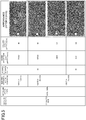
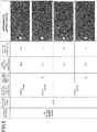
- FIG. 2 provides appearance photographs of the anode and cathode sites of a material under test (MUT) 1 of Comparative Example 3 in a corrosion resistance test described later.
- the "appearance photograph (before removal)” is the photograph of the surface of the coated metal material 1 after the test.
- the “appearance photograph (after removal)” is the photograph of the surface of the coated metal material 1 from which a swelling part of the electrodeposition coat 4 is removed with an adhesive tape.
- the formation of the artificial defect 5 but no swelling of the electrodeposition coat 4 can be observed.
- the cathode site the artificial defect 5 and the swelling part of the electrodeposition coat 4 around the artificial defect 5 are observed.
- the electrodes 12 surround the respective artificial defects 5. A voltage is thus stably applied to the electrodeposition coat 4 around the artificial defects 5. This leads to efficient migration of ions and efficient penetration of water into the electrodeposition coat 4 at the time of electrical conduction.
- the hydrogen gas is generated at the artificial defect 5 as described above. The hydrogen gas goes out through the through-hole 12a of the electrode 12, which hinders deterioration in the electrical conductivity.
- the water-containing material 6 is mud containing clay minerals, ions and water easily penetrate into the parts of the electrodeposition coat 4 around the artificial defects 5.
- the electrical conduction promotes the penetration of the ions and water into the parts of the electrodeposition coat 4 around the artificial defects 5 at the anode and cathode sites. Accordingly, the flow of electricity is rapidly stabilized. As a result, the corrosion stably spreads from the artificial defect 5 at the cathode site to the vicinity.
- the electrical conduction may be performed for, for example, 0.5 hours to 24 hours in view of sufficiently spreading the swelling of the coat.
- the electrical conduction time may be preferably from one hour to ten hours, and more preferably from one hour to five hours.
- the progress of corrosion at the cathode site appears as the development of the swelling of the electrodeposition coat 4, that is, the spread of the swelling of the coat.
- the corrosion resistances, particularly, the rates of corrosion progress of the MUTs can be evaluated.
- the corrosion resistances of the MUTs may be evaluated in association with the actual corrosion tests as follows.
- the relationship between the rates of corrosion progress (an increase in the size of the swelling part of the coat per unit time) according to the present corrosion tests and the actual corrosion tests are obtained in advance.
- the degrees of corrosion resistances can be obtained based on the results of the present corrosion resistance tests in correspondence to the actual corrosion tests.
- MUTs coated metal materials
- Table 1 Seven types of MUTs (coated metal materials) shown in Table 1 were prepared, among which the coating conditions, that is, chemical treatment times using zinc phosphate and baking conditions for electrodeposition coating were different.
- the metal substrate of each of MUTs 1 to 7 is the steel sheet 2, and the electrodeposition coat 4 has a thickness of 10 ⁇ m.
- the details of the coating conditions A to G shown in Table 1 are shown in Table 2.
- the corrosion resistance tests were performed in the manner shown in FIG. 1 .
- the artificial defects 5 having a size of 1 mm and reaching the steel sheet were introduced quantitatively, that is at a load (test force) of 30kg, to the MUTs at two points at a distance of 4 cm using a Vickers hardness tester.
- ring-shaped perforated electrodes made of platinum with an outer diameter of about 32 mm and an inner diameter of about 30 mm were used.
- the electrodes 12 are not limited to platinum electrodes and may also be other electrodes such as carbon electrodes.
- a hot plate was placed under the steel sheet and rubber heaters were wound around the cylinders to increase and maintain the temperatures of the steel sheet and the water-containing material 6 as shown in Table 1.
- Electricity was conducted by the conduction means 8 at a current value of 1 mA for the conduction time shown in Table 1.
- electricity was conducted immediately after the treatment.
- the MUTs were held at 70 °C for 30 minutes after the treatment and before the electrical conduction.
- the rates of corrosion progress were measured for the respective MUTs by the method described above in the corrosion resistance evaluation.
- Table 1 shows the rates of corrosion progress (the rates of swelling of the coats) obtained by the tests in Example 1 and Comparative Examples 1 to 4.
- Test Example 1 shows the rates of corrosion progress obtained as a result of actual corrosion tests in which the artificial defects 5 of the MUTs were attached with simulated mud and exposed to an environment at a temperature of 50 °C and a humidity of 98%.
- FIG. 3 shows the correlation between the rates of corrosion progress in Example 1 and in Test Example 1.
- the water-containing material 6 contains the clay minerals, and the holding precedes the electrical conduction.
- FIGS. 4 to 6 Various deposits were provided on the surfaces of various types of the electrodeposition coats 4 with different thicknesses under different baking conditions to examine the water absorption and swelling rates of the electrodeposition coats 4 after nine days.
- the following five types and states of the deposits are shown in FIGS. 4 to 6 : water, 5% of NaCl (spray), 5% of CaCl 2 (spray), simulated mud and 5% of NaCl (immersion).
- the simulated mud had significantly improved water absorption and swelling rate after nine days as compared to the water, 5% of NaCl (spray) and 5% of CaCl 2 (spray).
- the simulated mud has remarkably improved water absorption and swelling rate.
- FIG. 7 illustrates comparison in the rates of water penetrating into the coats among the five types where the electrodeposition coats 4 were baked under the conditions of 150°C ⁇ 20 min.
- the rates of water penetrating into the coats were calculated based on the time until the water absorption of the coats reached 25 ⁇ g/mm -3 . According to the figure, it is found that the simulated mud had largely increased rate of water penetrating into the coats as compared to the salt water spray, for example.
- the electricity is conducted to the metal substrate (steel sheet) 2 not only by the constant-current control method but may be a constant-voltage control method.
- FIG. 8 is a current plot of electrical conduction controlled at a constant current of 1 mA (the test of MUT 1 of Comparative Example 3).
- FIG. 9 is a current plot where a constant voltage is applied at which a current of 1 mA flows. The corrosion resistance tests were conducted by the constant-current control and the constant-voltage control under the same conditions as MUT 1 in Comparative Example 3 except the electrical conduction conditions.
- the current value varies a little at the initial value but controlled at about 1 mA. In this manner, the current value directly involved in the acceleration of corrosion is stabilized, which improves the reproducibility and acceleration of corrosion. That is, the reliability of the corrosion resistance tests improves.
- the method of testing corrosion resistance includes the holding before the electrical conduction, and thus reduces the variation in the current value from the start of the electrical conduction to about 7000 seconds. It is considered from the current plot (current waveform) in the constant-voltage control that the state and degree of corrosion in the stage in which the corrosion progresses are easily figured out.
- the artificial defects 5 may be omitted. While the electrodes 12 are arranged in the two positions in the first embodiment, an electrode 12 may be disposed in a position.
- a corrosion resistance tester includes an electrode 12, a conduction means 8 as a power supply and a current detector, and an information processing terminal 25 as a controller and a determiner.
- the conduction means 8 is connected to the electrode 12 and the steel sheet 2 of the coated metal material 1.
- the information processing terminal 25 is communicatively connected to the conduction means 8.
- the electrode 12 is for applying a voltage between the steel sheet 2 and the electrodeposition coat 4.
- the electrode 12 is a ring-shaped perforated electrode buried in a water-containing material 6 that is identical or similar to that in the first embodiment.
- the electrode 12 is disposed in parallel to the surface of the electrodeposition coat 4 but not in contact with the electrodeposition coat 4.
- a wire of the conduction means 8 is connected to the steel sheet 2.
- the water-containing material 6 is contained in a container 21 on the surface of the electrodeposition coat 4 with a rubber mat 23 for preventing and reducing liquid leakage interposed therebetween.
- the electrode 12 is slightly spaced apart from the electrodeposition coat 4 with the water-containing material 6 interposed therebetween.
- the contact area (measurement area) between the water-containing material 6 and the electrodeposition coat 4 may preferably range from 19.6 mm 2 to 314 mm 2 , for example. More preferably, the contact area may range from 50.2 mm 2 to 113 mm 2 . Note that the electrode 12 may be in contact with the electrodeposition coat 4.
- the conduction means 8 is connected to the electrode 12 and the steel sheet 2. While serving as a power supply for applying a voltage between the surface of the electrodeposition coat 4 and the steel sheet 2, the conduction means 8 also serves as a current detector for detecting a current flowing between the electrodeposition coat 4 and the steel sheet 2. Specifically, for example, a potentiostat/galvanostat that can be controlled as a voltage/current application method may be used.
- the information processing terminal 25 serves as a controller for controlling the voltage applied by the conduction means 8.
- the information processing terminal 25 also serves as a determiner for evaluating the corrosion resistance of the coated metal material 1 based on a value related to the current detected by the conduction means 8. This point will be described in detail in the following method of testing corrosion resistance.
- the information processing terminal 25 may be, for example, a general-purpose computer.
- the coated metal material 1 may include a multilayer film of two or more layers as the surface treatment film.
- the multilayer film may include, in addition to the electrodeposition coat 4, an intermediate coat on the surface of the electrodeposition coat 4 and selectively include a finish coat or the like on the intermediate coat.
- the intermediate coat serves to provide reliable finishing and chipping resistance of the coated metal material 1 and to improve the adhesion between the electrodeposition coat 4 and the finish coat.
- the finish coat provides reliable color, finishing, and weather resistance of the coating metal material 1.
- these coats may be made of, for example, a paint containing a base resin, such as a polyester resin, an acrylic resin, or an alkyd resin; and a crosslinking agent, such as a melamine resin, a urea resin, or a polyisocyanate compound (including a block copolymer).
- This configuration allows, in a manufacturing process of an automobile member, for example, taking out of parts from the manufacturing line in each coating step and check of the qualities of the coats.
- the water penetration enhancer is made of the clay minerals but not limited thereto, as long as functioning to promote the penetration of water into the electrodeposition coat 4.
- a solvent such as acetone, ethanol, toluene, or methanol; or a material improving the wettability of the coat may be used.
- the electrode(s) 12 may be provided with no through hole(s) 12a.
- the shape of the electrode(s) is not particularly limited.
- the electrode(s) may be in a shape generally used for electrochemical measurement.
- the present disclosure provides a method of testing corrosion resistance that promotes rapid and uniform migration of ions and penetration of water into a surface treatment film to improve the reliability of the corrosion resistance test and reduce the test time, and is thus significantly useful.
Landscapes
- Life Sciences & Earth Sciences (AREA)
- Health & Medical Sciences (AREA)
- Chemical & Material Sciences (AREA)
- Immunology (AREA)
- Pathology (AREA)
- Physics & Mathematics (AREA)
- General Physics & Mathematics (AREA)
- General Health & Medical Sciences (AREA)
- Analytical Chemistry (AREA)
- Biochemistry (AREA)
- Ecology (AREA)
- Environmental & Geological Engineering (AREA)
- Biodiversity & Conservation Biology (AREA)
- Environmental Sciences (AREA)
- Molecular Biology (AREA)
- Chemical Kinetics & Catalysis (AREA)
- Electrochemistry (AREA)
- Testing Resistance To Weather, Investigating Materials By Mechanical Methods (AREA)
- Investigating Or Analyzing Materials By The Use Of Electric Means (AREA)
Applications Claiming Priority (1)
| Application Number | Priority Date | Filing Date | Title |
|---|---|---|---|
| JP2018231983A JP6747495B2 (ja) | 2018-12-11 | 2018-12-11 | 被覆金属材の耐食性試験方法 |
Publications (2)
| Publication Number | Publication Date |
|---|---|
| EP3667293A1 true EP3667293A1 (de) | 2020-06-17 |
| EP3667293B1 EP3667293B1 (de) | 2022-02-02 |
Family
ID=68806624
Family Applications (1)
| Application Number | Title | Priority Date | Filing Date |
|---|---|---|---|
| EP19213764.4A Active EP3667293B1 (de) | 2018-12-11 | 2019-12-05 | Verfahren zur prüfung der korrosionsbeständigkeit von beschichtetem metallmaterial |
Country Status (4)
| Country | Link |
|---|---|
| US (1) | US11262329B2 (de) |
| EP (1) | EP3667293B1 (de) |
| JP (1) | JP6747495B2 (de) |
| CN (1) | CN111307705B (de) |
Cited By (3)
| Publication number | Priority date | Publication date | Assignee | Title |
|---|---|---|---|---|
| US20210010926A1 (en) * | 2017-08-04 | 2021-01-14 | Mazda Motor Corporation | Corrosion resistance test method and corrosion resistance test apparatus for coated metal material |
| EP3945303A3 (de) * | 2020-07-30 | 2022-03-16 | Mazda Motor Corporation | Korrosionsbeständigkeitstestvorrichtung und korrosionsbeständigkeitstestverfahren für beschichtetes metallmaterial |
| EP4624898A1 (de) * | 2024-03-28 | 2025-10-01 | Mazda Motor Corporation | Korrosionsbeständigkeitstestverfahren, korrosionsbeständigkeitstestvorrichtung und korrosionsbeständigkeitstestprogramm für beschichtetes metallmaterial und aufzeichnungsmedium |
Families Citing this family (9)
| Publication number | Priority date | Publication date | Assignee | Title |
|---|---|---|---|---|
| JP2020118468A (ja) * | 2019-01-18 | 2020-08-06 | マツダ株式会社 | 被覆金属材の耐食性試験装置 |
| JP7516904B2 (ja) * | 2020-06-19 | 2024-07-17 | マツダ株式会社 | 被覆金属材の耐食性試験方法及び試験片 |
| JP7484481B2 (ja) * | 2020-06-19 | 2024-05-16 | マツダ株式会社 | 被覆金属材の耐食性試験方法 |
| JP6801805B1 (ja) * | 2020-06-22 | 2020-12-16 | マツダ株式会社 | 計測方法及び計測装置、並びに、被覆金属材の耐食性試験方法及び耐食性試験装置 |
| JP6835280B1 (ja) * | 2020-06-22 | 2021-02-24 | マツダ株式会社 | 傷の処理方法及び処理装置、並びに、被覆金属材の耐食性試験方法及び耐食性試験装置 |
| JP6835279B1 (ja) * | 2020-06-22 | 2021-02-24 | マツダ株式会社 | 電極部装置、被覆金属材の耐食性試験方法及び耐食性試験装置 |
| JP6835286B1 (ja) * | 2020-09-29 | 2021-02-24 | マツダ株式会社 | 被覆金属材の耐食性試験方法及び該方法に用いられる含水材料 |
| JP6835287B1 (ja) * | 2020-09-29 | 2021-02-24 | マツダ株式会社 | 被覆金属材の耐食性試験方法及び該方法に用いられる含水材料 |
| JP7088396B1 (ja) * | 2021-10-01 | 2022-06-21 | マツダ株式会社 | 被覆金属材の耐食性試験方法、耐食性試験装置、耐食性試験用プログラム及び記録媒体 |
Citations (4)
| Publication number | Priority date | Publication date | Assignee | Title |
|---|---|---|---|---|
| US3293155A (en) * | 1965-07-12 | 1966-12-20 | Ford Motor Co | Method for determining the corrosion resistance of anodized aluminum parts |
| JP2007271501A (ja) | 2006-03-31 | 2007-10-18 | Osaka Gas Co Ltd | 被膜の防食評価方法 |
| JP2016050915A (ja) | 2014-09-02 | 2016-04-11 | 国立大学法人広島大学 | 塗装金属材の耐食性評価方法及び耐食性評価装置 |
| JP2016050916A (ja) | 2014-09-02 | 2016-04-11 | マツダ株式会社 | 塗装金属材の耐食性評価方法及び耐食性評価装置 |
Family Cites Families (16)
| Publication number | Priority date | Publication date | Assignee | Title |
|---|---|---|---|---|
| JPS5890157A (ja) * | 1981-11-25 | 1983-05-28 | Kawasaki Steel Corp | 外面被覆鋼管または鋼板の陰極剥離試験方法および装置 |
| JPS6091250A (ja) * | 1983-10-25 | 1985-05-22 | Toshiba Corp | 電気化学測定方法 |
| JP4051409B2 (ja) * | 1997-07-15 | 2008-02-27 | 日本防蝕工業株式会社 | 大気環境中の塗装金属体の電気防食装置 |
| JP5108844B2 (ja) * | 2009-05-12 | 2012-12-26 | 住友電気工業株式会社 | 腐食試験方法 |
| JP5108843B2 (ja) * | 2009-08-06 | 2012-12-26 | 住友電気工業株式会社 | 腐食試験方法 |
| JP5238083B2 (ja) * | 2009-01-02 | 2013-07-17 | イー・アイ・デュポン・ドウ・ヌムール・アンド・カンパニー | 耐食性評価装置 |
| CN103502794A (zh) * | 2010-12-21 | 2014-01-08 | 涂层国外知识产权有限公司 | 用于评估涂层耐腐蚀性的方法 |
| US9212986B2 (en) * | 2010-12-21 | 2015-12-15 | Axalta Coating Systems Ip Co., Llc | Process of evaluating corrosion resistance |
| CN102183453A (zh) * | 2011-01-24 | 2011-09-14 | 南通宝钢钢铁有限公司 | 一种耐氯离子腐蚀抗震钢材的微观电极电位的测定方法 |
| JP5830910B2 (ja) * | 2011-04-12 | 2015-12-09 | Jfeスチール株式会社 | 缶成型体の内容物に対する耐腐食性を評価する方法 |
| CN102691059A (zh) * | 2012-06-18 | 2012-09-26 | 深圳市诚达科技股份有限公司 | 一种在高腐蚀环境中不锈钢抗腐蚀的表面处理方法 |
| JP5588539B2 (ja) * | 2013-04-23 | 2014-09-10 | セイコーインスツル株式会社 | 電気化学セル |
| CN204142965U (zh) * | 2014-08-08 | 2015-02-04 | 苏州格林泰克科技有限公司 | 一种不极化电极 |
| CN104458536A (zh) * | 2014-12-16 | 2015-03-25 | 天津大学 | 一种测量混凝土离子渗透率的装置和方法及其应用 |
| EP3660488B1 (de) | 2017-08-04 | 2023-03-15 | Mazda Motor Corporation | Korrosionsbeständigkeitstestverfahren und korrosionsbeständigkeitstestvorrichtung für beschichtetes metallmaterial |
| CN108823439A (zh) * | 2018-07-19 | 2018-11-16 | 佛山市高明区爪和新材料科技有限公司 | 一种高强型生物用锌镁合金复合材料的制备方法 |
-
2018
- 2018-12-11 JP JP2018231983A patent/JP6747495B2/ja active Active
-
2019
- 2019-12-02 US US16/699,848 patent/US11262329B2/en active Active
- 2019-12-05 EP EP19213764.4A patent/EP3667293B1/de active Active
- 2019-12-05 CN CN201911232024.9A patent/CN111307705B/zh active Active
Patent Citations (4)
| Publication number | Priority date | Publication date | Assignee | Title |
|---|---|---|---|---|
| US3293155A (en) * | 1965-07-12 | 1966-12-20 | Ford Motor Co | Method for determining the corrosion resistance of anodized aluminum parts |
| JP2007271501A (ja) | 2006-03-31 | 2007-10-18 | Osaka Gas Co Ltd | 被膜の防食評価方法 |
| JP2016050915A (ja) | 2014-09-02 | 2016-04-11 | 国立大学法人広島大学 | 塗装金属材の耐食性評価方法及び耐食性評価装置 |
| JP2016050916A (ja) | 2014-09-02 | 2016-04-11 | マツダ株式会社 | 塗装金属材の耐食性評価方法及び耐食性評価装置 |
Non-Patent Citations (1)
| Title |
|---|
| SJÖGREN L ET AL: "Corrosion resistance of stainless steel pipes in soil", MATERIALS AND CORROSION, WILEY, vol. 62, no. 4, 1 April 2011 (2011-04-01), pages 299 - 309, XP001561849, ISSN: 0947-5117, [retrieved on 20100114], DOI: 10.1002/MACO.200905552 * |
Cited By (4)
| Publication number | Priority date | Publication date | Assignee | Title |
|---|---|---|---|---|
| US20210010926A1 (en) * | 2017-08-04 | 2021-01-14 | Mazda Motor Corporation | Corrosion resistance test method and corrosion resistance test apparatus for coated metal material |
| US11519844B2 (en) * | 2017-08-04 | 2022-12-06 | Mazda Motor Corporation | Corrosion resistance test method and corrosion resistance test apparatus for coated metal material |
| EP3945303A3 (de) * | 2020-07-30 | 2022-03-16 | Mazda Motor Corporation | Korrosionsbeständigkeitstestvorrichtung und korrosionsbeständigkeitstestverfahren für beschichtetes metallmaterial |
| EP4624898A1 (de) * | 2024-03-28 | 2025-10-01 | Mazda Motor Corporation | Korrosionsbeständigkeitstestverfahren, korrosionsbeständigkeitstestvorrichtung und korrosionsbeständigkeitstestprogramm für beschichtetes metallmaterial und aufzeichnungsmedium |
Also Published As
| Publication number | Publication date |
|---|---|
| CN111307705A (zh) | 2020-06-19 |
| JP2020094881A (ja) | 2020-06-18 |
| CN111307705B (zh) | 2023-05-09 |
| EP3667293B1 (de) | 2022-02-02 |
| JP6747495B2 (ja) | 2020-08-26 |
| US11262329B2 (en) | 2022-03-01 |
| US20200182824A1 (en) | 2020-06-11 |
Similar Documents
| Publication | Publication Date | Title |
|---|---|---|
| EP3667293B1 (de) | Verfahren zur prüfung der korrosionsbeständigkeit von beschichtetem metallmaterial | |
| EP3686575B1 (de) | Korrosionsbeständigkeitstester für beschichtetes metallmaterial | |
| CN111033224B (zh) | 包覆金属材料的耐腐蚀性试验方法和装置 | |
| JP6213426B2 (ja) | 塗装金属材の耐食性評価方法及び耐食性評価装置 | |
| JP6565980B2 (ja) | 被覆金属材の耐食性試験装置及び被覆金属材の耐食性試験方法 | |
| JP6565979B2 (ja) | 被覆金属材の耐食性試験装置及び耐食性試験方法 | |
| JP6733844B1 (ja) | 被覆金属材の耐食性試験方法及び耐食性試験装置 | |
| JP6515963B2 (ja) | 被覆金属材の耐食性試験方法及び耐食性試験装置 | |
| EP3929564B1 (de) | Messverfahren und messvorrichtung und korrosionsbeständigkeitstestverfahren und korrosionsbeständigkeitstestvorrichtung für beschichtetes metallmaterial | |
| EP3929562A2 (de) | Elektrodenabschnittvorrichtung sowie vorrichtung zur prüfung der korrosionsbeständigkeit eines beschichteten metallmaterials | |
| EP3940367A1 (de) | Verfahren und vorrichtung zur behandlung von beschädigten bereichen sowie verfahren und vorrichtung zur prüfung der korrosionsbeständigkeit eines beschichteten metallmaterials | |
| JP6813122B2 (ja) | 被覆金属材の耐食性試験方法 | |
| JP7516904B2 (ja) | 被覆金属材の耐食性試験方法及び試験片 | |
| Losch et al. | Impedance spectroscopy and other electrochemical in-situ investigations of the phosphating process | |
| CN115931689A (zh) | 被覆金属材料的耐腐蚀性试验方法、耐腐蚀性试验装置、耐腐蚀性试验用程序及记录介质 | |
| JP2017211217A (ja) | 耐食性の評価方法およびめっき製品の修復方法 | |
| JP2025152153A (ja) | 被覆金属材の試験方法 |
Legal Events
| Date | Code | Title | Description |
|---|---|---|---|
| PUAI | Public reference made under article 153(3) epc to a published international application that has entered the european phase |
Free format text: ORIGINAL CODE: 0009012 |
|
| STAA | Information on the status of an ep patent application or granted ep patent |
Free format text: STATUS: THE APPLICATION HAS BEEN PUBLISHED |
|
| AK | Designated contracting states |
Kind code of ref document: A1 Designated state(s): AL AT BE BG CH CY CZ DE DK EE ES FI FR GB GR HR HU IE IS IT LI LT LU LV MC MK MT NL NO PL PT RO RS SE SI SK SM TR |
|
| AX | Request for extension of the european patent |
Extension state: BA ME |
|
| STAA | Information on the status of an ep patent application or granted ep patent |
Free format text: STATUS: REQUEST FOR EXAMINATION WAS MADE |
|
| 17P | Request for examination filed |
Effective date: 20201209 |
|
| STAA | Information on the status of an ep patent application or granted ep patent |
Free format text: STATUS: EXAMINATION IS IN PROGRESS |
|
| 17Q | First examination report despatched |
Effective date: 20210204 |
|
| RIC1 | Information provided on ipc code assigned before grant |
Ipc: G01N 17/02 20060101AFI20210414BHEP Ipc: G01N 17/00 20060101ALI20210414BHEP |
|
| GRAP | Despatch of communication of intention to grant a patent |
Free format text: ORIGINAL CODE: EPIDOSNIGR1 |
|
| STAA | Information on the status of an ep patent application or granted ep patent |
Free format text: STATUS: GRANT OF PATENT IS INTENDED |
|
| RIC1 | Information provided on ipc code assigned before grant |
Ipc: G01N 17/00 20060101ALI20210811BHEP Ipc: G01N 17/02 20060101AFI20210811BHEP |
|
| INTG | Intention to grant announced |
Effective date: 20210831 |
|
| GRAS | Grant fee paid |
Free format text: ORIGINAL CODE: EPIDOSNIGR3 |
|
| GRAA | (expected) grant |
Free format text: ORIGINAL CODE: 0009210 |
|
| STAA | Information on the status of an ep patent application or granted ep patent |
Free format text: STATUS: THE PATENT HAS BEEN GRANTED |
|
| AK | Designated contracting states |
Kind code of ref document: B1 Designated state(s): AL AT BE BG CH CY CZ DE DK EE ES FI FR GB GR HR HU IE IS IT LI LT LU LV MC MK MT NL NO PL PT RO RS SE SI SK SM TR |
|
| REG | Reference to a national code |
Ref country code: GB Ref legal event code: FG4D |
|
| REG | Reference to a national code |
Ref country code: CH Ref legal event code: EP Ref country code: AT Ref legal event code: REF Ref document number: 1466708 Country of ref document: AT Kind code of ref document: T Effective date: 20220215 |
|
| REG | Reference to a national code |
Ref country code: DE Ref legal event code: R096 Ref document number: 602019011336 Country of ref document: DE |
|
| REG | Reference to a national code |
Ref country code: IE Ref legal event code: FG4D |
|
| REG | Reference to a national code |
Ref country code: LT Ref legal event code: MG9D |
|
| REG | Reference to a national code |
Ref country code: NL Ref legal event code: MP Effective date: 20220202 |
|
| REG | Reference to a national code |
Ref country code: AT Ref legal event code: MK05 Ref document number: 1466708 Country of ref document: AT Kind code of ref document: T Effective date: 20220202 |
|
| PG25 | Lapsed in a contracting state [announced via postgrant information from national office to epo] |
Ref country code: SE Free format text: LAPSE BECAUSE OF FAILURE TO SUBMIT A TRANSLATION OF THE DESCRIPTION OR TO PAY THE FEE WITHIN THE PRESCRIBED TIME-LIMIT Effective date: 20220202 Ref country code: RS Free format text: LAPSE BECAUSE OF FAILURE TO SUBMIT A TRANSLATION OF THE DESCRIPTION OR TO PAY THE FEE WITHIN THE PRESCRIBED TIME-LIMIT Effective date: 20220202 Ref country code: PT Free format text: LAPSE BECAUSE OF FAILURE TO SUBMIT A TRANSLATION OF THE DESCRIPTION OR TO PAY THE FEE WITHIN THE PRESCRIBED TIME-LIMIT Effective date: 20220602 Ref country code: NO Free format text: LAPSE BECAUSE OF FAILURE TO SUBMIT A TRANSLATION OF THE DESCRIPTION OR TO PAY THE FEE WITHIN THE PRESCRIBED TIME-LIMIT Effective date: 20220502 Ref country code: NL Free format text: LAPSE BECAUSE OF FAILURE TO SUBMIT A TRANSLATION OF THE DESCRIPTION OR TO PAY THE FEE WITHIN THE PRESCRIBED TIME-LIMIT Effective date: 20220202 Ref country code: LT Free format text: LAPSE BECAUSE OF FAILURE TO SUBMIT A TRANSLATION OF THE DESCRIPTION OR TO PAY THE FEE WITHIN THE PRESCRIBED TIME-LIMIT Effective date: 20220202 Ref country code: HR Free format text: LAPSE BECAUSE OF FAILURE TO SUBMIT A TRANSLATION OF THE DESCRIPTION OR TO PAY THE FEE WITHIN THE PRESCRIBED TIME-LIMIT Effective date: 20220202 Ref country code: ES Free format text: LAPSE BECAUSE OF FAILURE TO SUBMIT A TRANSLATION OF THE DESCRIPTION OR TO PAY THE FEE WITHIN THE PRESCRIBED TIME-LIMIT Effective date: 20220202 Ref country code: BG Free format text: LAPSE BECAUSE OF FAILURE TO SUBMIT A TRANSLATION OF THE DESCRIPTION OR TO PAY THE FEE WITHIN THE PRESCRIBED TIME-LIMIT Effective date: 20220502 |
|
| PG25 | Lapsed in a contracting state [announced via postgrant information from national office to epo] |
Ref country code: PL Free format text: LAPSE BECAUSE OF FAILURE TO SUBMIT A TRANSLATION OF THE DESCRIPTION OR TO PAY THE FEE WITHIN THE PRESCRIBED TIME-LIMIT Effective date: 20220202 Ref country code: LV Free format text: LAPSE BECAUSE OF FAILURE TO SUBMIT A TRANSLATION OF THE DESCRIPTION OR TO PAY THE FEE WITHIN THE PRESCRIBED TIME-LIMIT Effective date: 20220202 Ref country code: GR Free format text: LAPSE BECAUSE OF FAILURE TO SUBMIT A TRANSLATION OF THE DESCRIPTION OR TO PAY THE FEE WITHIN THE PRESCRIBED TIME-LIMIT Effective date: 20220503 Ref country code: FI Free format text: LAPSE BECAUSE OF FAILURE TO SUBMIT A TRANSLATION OF THE DESCRIPTION OR TO PAY THE FEE WITHIN THE PRESCRIBED TIME-LIMIT Effective date: 20220202 Ref country code: AT Free format text: LAPSE BECAUSE OF FAILURE TO SUBMIT A TRANSLATION OF THE DESCRIPTION OR TO PAY THE FEE WITHIN THE PRESCRIBED TIME-LIMIT Effective date: 20220202 |
|
| PG25 | Lapsed in a contracting state [announced via postgrant information from national office to epo] |
Ref country code: IS Free format text: LAPSE BECAUSE OF FAILURE TO SUBMIT A TRANSLATION OF THE DESCRIPTION OR TO PAY THE FEE WITHIN THE PRESCRIBED TIME-LIMIT Effective date: 20220602 |
|
| PG25 | Lapsed in a contracting state [announced via postgrant information from national office to epo] |
Ref country code: SM Free format text: LAPSE BECAUSE OF FAILURE TO SUBMIT A TRANSLATION OF THE DESCRIPTION OR TO PAY THE FEE WITHIN THE PRESCRIBED TIME-LIMIT Effective date: 20220202 Ref country code: SK Free format text: LAPSE BECAUSE OF FAILURE TO SUBMIT A TRANSLATION OF THE DESCRIPTION OR TO PAY THE FEE WITHIN THE PRESCRIBED TIME-LIMIT Effective date: 20220202 Ref country code: RO Free format text: LAPSE BECAUSE OF FAILURE TO SUBMIT A TRANSLATION OF THE DESCRIPTION OR TO PAY THE FEE WITHIN THE PRESCRIBED TIME-LIMIT Effective date: 20220202 Ref country code: EE Free format text: LAPSE BECAUSE OF FAILURE TO SUBMIT A TRANSLATION OF THE DESCRIPTION OR TO PAY THE FEE WITHIN THE PRESCRIBED TIME-LIMIT Effective date: 20220202 Ref country code: DK Free format text: LAPSE BECAUSE OF FAILURE TO SUBMIT A TRANSLATION OF THE DESCRIPTION OR TO PAY THE FEE WITHIN THE PRESCRIBED TIME-LIMIT Effective date: 20220202 Ref country code: CZ Free format text: LAPSE BECAUSE OF FAILURE TO SUBMIT A TRANSLATION OF THE DESCRIPTION OR TO PAY THE FEE WITHIN THE PRESCRIBED TIME-LIMIT Effective date: 20220202 |
|
| REG | Reference to a national code |
Ref country code: DE Ref legal event code: R097 Ref document number: 602019011336 Country of ref document: DE |
|
| PG25 | Lapsed in a contracting state [announced via postgrant information from national office to epo] |
Ref country code: AL Free format text: LAPSE BECAUSE OF FAILURE TO SUBMIT A TRANSLATION OF THE DESCRIPTION OR TO PAY THE FEE WITHIN THE PRESCRIBED TIME-LIMIT Effective date: 20220202 |
|
| PLBE | No opposition filed within time limit |
Free format text: ORIGINAL CODE: 0009261 |
|
| STAA | Information on the status of an ep patent application or granted ep patent |
Free format text: STATUS: NO OPPOSITION FILED WITHIN TIME LIMIT |
|
| 26N | No opposition filed |
Effective date: 20221103 |
|
| PG25 | Lapsed in a contracting state [announced via postgrant information from national office to epo] |
Ref country code: SI Free format text: LAPSE BECAUSE OF FAILURE TO SUBMIT A TRANSLATION OF THE DESCRIPTION OR TO PAY THE FEE WITHIN THE PRESCRIBED TIME-LIMIT Effective date: 20220202 |
|
| PG25 | Lapsed in a contracting state [announced via postgrant information from national office to epo] |
Ref country code: IT Free format text: LAPSE BECAUSE OF FAILURE TO SUBMIT A TRANSLATION OF THE DESCRIPTION OR TO PAY THE FEE WITHIN THE PRESCRIBED TIME-LIMIT Effective date: 20220202 |
|
| REG | Reference to a national code |
Ref country code: CH Ref legal event code: PL |
|
| REG | Reference to a national code |
Ref country code: BE Ref legal event code: MM Effective date: 20221231 |
|
| PG25 | Lapsed in a contracting state [announced via postgrant information from national office to epo] |
Ref country code: LU Free format text: LAPSE BECAUSE OF NON-PAYMENT OF DUE FEES Effective date: 20221205 |
|
| PG25 | Lapsed in a contracting state [announced via postgrant information from national office to epo] |
Ref country code: LI Free format text: LAPSE BECAUSE OF NON-PAYMENT OF DUE FEES Effective date: 20221231 Ref country code: IE Free format text: LAPSE BECAUSE OF NON-PAYMENT OF DUE FEES Effective date: 20221205 Ref country code: CH Free format text: LAPSE BECAUSE OF NON-PAYMENT OF DUE FEES Effective date: 20221231 |
|
| PG25 | Lapsed in a contracting state [announced via postgrant information from national office to epo] |
Ref country code: FR Free format text: LAPSE BECAUSE OF NON-PAYMENT OF DUE FEES Effective date: 20221231 Ref country code: BE Free format text: LAPSE BECAUSE OF NON-PAYMENT OF DUE FEES Effective date: 20221231 |
|
| PG25 | Lapsed in a contracting state [announced via postgrant information from national office to epo] |
Ref country code: HU Free format text: LAPSE BECAUSE OF FAILURE TO SUBMIT A TRANSLATION OF THE DESCRIPTION OR TO PAY THE FEE WITHIN THE PRESCRIBED TIME-LIMIT; INVALID AB INITIO Effective date: 20191205 |
|
| PG25 | Lapsed in a contracting state [announced via postgrant information from national office to epo] |
Ref country code: CY Free format text: LAPSE BECAUSE OF FAILURE TO SUBMIT A TRANSLATION OF THE DESCRIPTION OR TO PAY THE FEE WITHIN THE PRESCRIBED TIME-LIMIT Effective date: 20220202 |
|
| PG25 | Lapsed in a contracting state [announced via postgrant information from national office to epo] |
Ref country code: MK Free format text: LAPSE BECAUSE OF FAILURE TO SUBMIT A TRANSLATION OF THE DESCRIPTION OR TO PAY THE FEE WITHIN THE PRESCRIBED TIME-LIMIT Effective date: 20220202 |
|
| PG25 | Lapsed in a contracting state [announced via postgrant information from national office to epo] |
Ref country code: MC Free format text: LAPSE BECAUSE OF FAILURE TO SUBMIT A TRANSLATION OF THE DESCRIPTION OR TO PAY THE FEE WITHIN THE PRESCRIBED TIME-LIMIT Effective date: 20220202 |
|
| PG25 | Lapsed in a contracting state [announced via postgrant information from national office to epo] |
Ref country code: TR Free format text: LAPSE BECAUSE OF FAILURE TO SUBMIT A TRANSLATION OF THE DESCRIPTION OR TO PAY THE FEE WITHIN THE PRESCRIBED TIME-LIMIT Effective date: 20220202 Ref country code: MC Free format text: LAPSE BECAUSE OF FAILURE TO SUBMIT A TRANSLATION OF THE DESCRIPTION OR TO PAY THE FEE WITHIN THE PRESCRIBED TIME-LIMIT Effective date: 20220202 |
|
| GBPC | Gb: european patent ceased through non-payment of renewal fee |
Effective date: 20231205 |
|
| PG25 | Lapsed in a contracting state [announced via postgrant information from national office to epo] |
Ref country code: MT Free format text: LAPSE BECAUSE OF FAILURE TO SUBMIT A TRANSLATION OF THE DESCRIPTION OR TO PAY THE FEE WITHIN THE PRESCRIBED TIME-LIMIT Effective date: 20220202 |
|
| PG25 | Lapsed in a contracting state [announced via postgrant information from national office to epo] |
Ref country code: GB Free format text: LAPSE BECAUSE OF NON-PAYMENT OF DUE FEES Effective date: 20231205 |
|
| PG25 | Lapsed in a contracting state [announced via postgrant information from national office to epo] |
Ref country code: GB Free format text: LAPSE BECAUSE OF NON-PAYMENT OF DUE FEES Effective date: 20231205 |
|
| PGFP | Annual fee paid to national office [announced via postgrant information from national office to epo] |
Ref country code: DE Payment date: 20251028 Year of fee payment: 7 |