EP3667153B1 - Spülbarer druckbehälter - Google Patents
Spülbarer druckbehälter Download PDFInfo
- Publication number
- EP3667153B1 EP3667153B1 EP20150019.6A EP20150019A EP3667153B1 EP 3667153 B1 EP3667153 B1 EP 3667153B1 EP 20150019 A EP20150019 A EP 20150019A EP 3667153 B1 EP3667153 B1 EP 3667153B1
- Authority
- EP
- European Patent Office
- Prior art keywords
- flushing lance
- pressure vessel
- gas
- storage volume
- filling
- Prior art date
- Legal status (The legal status is an assumption and is not a legal conclusion. Google has not performed a legal analysis and makes no representation as to the accuracy of the status listed.)
- Active
Links
Images


Classifications
-
- F—MECHANICAL ENGINEERING; LIGHTING; HEATING; WEAPONS; BLASTING
- F17—STORING OR DISTRIBUTING GASES OR LIQUIDS
- F17C—VESSELS FOR CONTAINING OR STORING COMPRESSED, LIQUEFIED OR SOLIDIFIED GASES; FIXED-CAPACITY GAS-HOLDERS; FILLING VESSELS WITH, OR DISCHARGING FROM VESSELS, COMPRESSED, LIQUEFIED, OR SOLIDIFIED GASES
- F17C1/00—Pressure vessels, e.g. gas cylinder, gas tank, replaceable cartridge
- F17C1/02—Pressure vessels, e.g. gas cylinder, gas tank, replaceable cartridge involving reinforcing arrangements
-
- F—MECHANICAL ENGINEERING; LIGHTING; HEATING; WEAPONS; BLASTING
- F17—STORING OR DISTRIBUTING GASES OR LIQUIDS
- F17C—VESSELS FOR CONTAINING OR STORING COMPRESSED, LIQUEFIED OR SOLIDIFIED GASES; FIXED-CAPACITY GAS-HOLDERS; FILLING VESSELS WITH, OR DISCHARGING FROM VESSELS, COMPRESSED, LIQUEFIED, OR SOLIDIFIED GASES
- F17C1/00—Pressure vessels, e.g. gas cylinder, gas tank, replaceable cartridge
-
- F—MECHANICAL ENGINEERING; LIGHTING; HEATING; WEAPONS; BLASTING
- F17—STORING OR DISTRIBUTING GASES OR LIQUIDS
- F17C—VESSELS FOR CONTAINING OR STORING COMPRESSED, LIQUEFIED OR SOLIDIFIED GASES; FIXED-CAPACITY GAS-HOLDERS; FILLING VESSELS WITH, OR DISCHARGING FROM VESSELS, COMPRESSED, LIQUEFIED, OR SOLIDIFIED GASES
- F17C5/00—Methods or apparatus for filling containers with liquefied, solidified, or compressed gases under pressures
- F17C5/06—Methods or apparatus for filling containers with liquefied, solidified, or compressed gases under pressures for filling with compressed gases
-
- F—MECHANICAL ENGINEERING; LIGHTING; HEATING; WEAPONS; BLASTING
- F17—STORING OR DISTRIBUTING GASES OR LIQUIDS
- F17C—VESSELS FOR CONTAINING OR STORING COMPRESSED, LIQUEFIED OR SOLIDIFIED GASES; FIXED-CAPACITY GAS-HOLDERS; FILLING VESSELS WITH, OR DISCHARGING FROM VESSELS, COMPRESSED, LIQUEFIED, OR SOLIDIFIED GASES
- F17C2201/00—Vessel construction, in particular geometry, arrangement or size
- F17C2201/01—Shape
- F17C2201/0104—Shape cylindrical
- F17C2201/0109—Shape cylindrical with exteriorly curved end-piece
-
- F—MECHANICAL ENGINEERING; LIGHTING; HEATING; WEAPONS; BLASTING
- F17—STORING OR DISTRIBUTING GASES OR LIQUIDS
- F17C—VESSELS FOR CONTAINING OR STORING COMPRESSED, LIQUEFIED OR SOLIDIFIED GASES; FIXED-CAPACITY GAS-HOLDERS; FILLING VESSELS WITH, OR DISCHARGING FROM VESSELS, COMPRESSED, LIQUEFIED, OR SOLIDIFIED GASES
- F17C2201/00—Vessel construction, in particular geometry, arrangement or size
- F17C2201/05—Size
- F17C2201/056—Small (<1 m3)
-
- F—MECHANICAL ENGINEERING; LIGHTING; HEATING; WEAPONS; BLASTING
- F17—STORING OR DISTRIBUTING GASES OR LIQUIDS
- F17C—VESSELS FOR CONTAINING OR STORING COMPRESSED, LIQUEFIED OR SOLIDIFIED GASES; FIXED-CAPACITY GAS-HOLDERS; FILLING VESSELS WITH, OR DISCHARGING FROM VESSELS, COMPRESSED, LIQUEFIED, OR SOLIDIFIED GASES
- F17C2201/00—Vessel construction, in particular geometry, arrangement or size
- F17C2201/05—Size
- F17C2201/058—Size portable (<30 l)
-
- F—MECHANICAL ENGINEERING; LIGHTING; HEATING; WEAPONS; BLASTING
- F17—STORING OR DISTRIBUTING GASES OR LIQUIDS
- F17C—VESSELS FOR CONTAINING OR STORING COMPRESSED, LIQUEFIED OR SOLIDIFIED GASES; FIXED-CAPACITY GAS-HOLDERS; FILLING VESSELS WITH, OR DISCHARGING FROM VESSELS, COMPRESSED, LIQUEFIED, OR SOLIDIFIED GASES
- F17C2203/00—Vessel construction, in particular walls or details thereof
- F17C2203/06—Materials for walls or layers thereof; Properties or structures of walls or their materials
- F17C2203/0602—Wall structures; Special features thereof
- F17C2203/0604—Liners
-
- F—MECHANICAL ENGINEERING; LIGHTING; HEATING; WEAPONS; BLASTING
- F17—STORING OR DISTRIBUTING GASES OR LIQUIDS
- F17C—VESSELS FOR CONTAINING OR STORING COMPRESSED, LIQUEFIED OR SOLIDIFIED GASES; FIXED-CAPACITY GAS-HOLDERS; FILLING VESSELS WITH, OR DISCHARGING FROM VESSELS, COMPRESSED, LIQUEFIED, OR SOLIDIFIED GASES
- F17C2203/00—Vessel construction, in particular walls or details thereof
- F17C2203/06—Materials for walls or layers thereof; Properties or structures of walls or their materials
- F17C2203/0602—Wall structures; Special features thereof
- F17C2203/0612—Wall structures
- F17C2203/0614—Single wall
- F17C2203/0619—Single wall with two layers
-
- F—MECHANICAL ENGINEERING; LIGHTING; HEATING; WEAPONS; BLASTING
- F17—STORING OR DISTRIBUTING GASES OR LIQUIDS
- F17C—VESSELS FOR CONTAINING OR STORING COMPRESSED, LIQUEFIED OR SOLIDIFIED GASES; FIXED-CAPACITY GAS-HOLDERS; FILLING VESSELS WITH, OR DISCHARGING FROM VESSELS, COMPRESSED, LIQUEFIED, OR SOLIDIFIED GASES
- F17C2203/00—Vessel construction, in particular walls or details thereof
- F17C2203/06—Materials for walls or layers thereof; Properties or structures of walls or their materials
- F17C2203/0634—Materials for walls or layers thereof
- F17C2203/0658—Synthetics
- F17C2203/066—Plastics
-
- F—MECHANICAL ENGINEERING; LIGHTING; HEATING; WEAPONS; BLASTING
- F17—STORING OR DISTRIBUTING GASES OR LIQUIDS
- F17C—VESSELS FOR CONTAINING OR STORING COMPRESSED, LIQUEFIED OR SOLIDIFIED GASES; FIXED-CAPACITY GAS-HOLDERS; FILLING VESSELS WITH, OR DISCHARGING FROM VESSELS, COMPRESSED, LIQUEFIED, OR SOLIDIFIED GASES
- F17C2203/00—Vessel construction, in particular walls or details thereof
- F17C2203/06—Materials for walls or layers thereof; Properties or structures of walls or their materials
- F17C2203/0634—Materials for walls or layers thereof
- F17C2203/0658—Synthetics
- F17C2203/0663—Synthetics in form of fibers or filaments
-
- F—MECHANICAL ENGINEERING; LIGHTING; HEATING; WEAPONS; BLASTING
- F17—STORING OR DISTRIBUTING GASES OR LIQUIDS
- F17C—VESSELS FOR CONTAINING OR STORING COMPRESSED, LIQUEFIED OR SOLIDIFIED GASES; FIXED-CAPACITY GAS-HOLDERS; FILLING VESSELS WITH, OR DISCHARGING FROM VESSELS, COMPRESSED, LIQUEFIED, OR SOLIDIFIED GASES
- F17C2203/00—Vessel construction, in particular walls or details thereof
- F17C2203/06—Materials for walls or layers thereof; Properties or structures of walls or their materials
- F17C2203/0634—Materials for walls or layers thereof
- F17C2203/0658—Synthetics
- F17C2203/0663—Synthetics in form of fibers or filaments
- F17C2203/0673—Polymers
-
- F—MECHANICAL ENGINEERING; LIGHTING; HEATING; WEAPONS; BLASTING
- F17—STORING OR DISTRIBUTING GASES OR LIQUIDS
- F17C—VESSELS FOR CONTAINING OR STORING COMPRESSED, LIQUEFIED OR SOLIDIFIED GASES; FIXED-CAPACITY GAS-HOLDERS; FILLING VESSELS WITH, OR DISCHARGING FROM VESSELS, COMPRESSED, LIQUEFIED, OR SOLIDIFIED GASES
- F17C2205/00—Vessel construction, in particular mounting arrangements, attachments or identifications means
- F17C2205/01—Mounting arrangements
- F17C2205/0103—Exterior arrangements
- F17C2205/0111—Boxes
-
- F—MECHANICAL ENGINEERING; LIGHTING; HEATING; WEAPONS; BLASTING
- F17—STORING OR DISTRIBUTING GASES OR LIQUIDS
- F17C—VESSELS FOR CONTAINING OR STORING COMPRESSED, LIQUEFIED OR SOLIDIFIED GASES; FIXED-CAPACITY GAS-HOLDERS; FILLING VESSELS WITH, OR DISCHARGING FROM VESSELS, COMPRESSED, LIQUEFIED, OR SOLIDIFIED GASES
- F17C2205/00—Vessel construction, in particular mounting arrangements, attachments or identifications means
- F17C2205/01—Mounting arrangements
- F17C2205/0123—Mounting arrangements characterised by number of vessels
- F17C2205/013—Two or more vessels
- F17C2205/0134—Two or more vessels characterised by the presence of fluid connection between vessels
- F17C2205/0142—Two or more vessels characterised by the presence of fluid connection between vessels bundled in parallel
-
- F—MECHANICAL ENGINEERING; LIGHTING; HEATING; WEAPONS; BLASTING
- F17—STORING OR DISTRIBUTING GASES OR LIQUIDS
- F17C—VESSELS FOR CONTAINING OR STORING COMPRESSED, LIQUEFIED OR SOLIDIFIED GASES; FIXED-CAPACITY GAS-HOLDERS; FILLING VESSELS WITH, OR DISCHARGING FROM VESSELS, COMPRESSED, LIQUEFIED, OR SOLIDIFIED GASES
- F17C2205/00—Vessel construction, in particular mounting arrangements, attachments or identifications means
- F17C2205/03—Fluid connections, filters, valves, closure means or other attachments
- F17C2205/0302—Fittings, valves, filters, or components in connection with the gas storage device
- F17C2205/0305—Bosses, e.g. boss collars
-
- F—MECHANICAL ENGINEERING; LIGHTING; HEATING; WEAPONS; BLASTING
- F17—STORING OR DISTRIBUTING GASES OR LIQUIDS
- F17C—VESSELS FOR CONTAINING OR STORING COMPRESSED, LIQUEFIED OR SOLIDIFIED GASES; FIXED-CAPACITY GAS-HOLDERS; FILLING VESSELS WITH, OR DISCHARGING FROM VESSELS, COMPRESSED, LIQUEFIED, OR SOLIDIFIED GASES
- F17C2205/00—Vessel construction, in particular mounting arrangements, attachments or identifications means
- F17C2205/03—Fluid connections, filters, valves, closure means or other attachments
- F17C2205/0302—Fittings, valves, filters, or components in connection with the gas storage device
- F17C2205/0352—Pipes
-
- F—MECHANICAL ENGINEERING; LIGHTING; HEATING; WEAPONS; BLASTING
- F17—STORING OR DISTRIBUTING GASES OR LIQUIDS
- F17C—VESSELS FOR CONTAINING OR STORING COMPRESSED, LIQUEFIED OR SOLIDIFIED GASES; FIXED-CAPACITY GAS-HOLDERS; FILLING VESSELS WITH, OR DISCHARGING FROM VESSELS, COMPRESSED, LIQUEFIED, OR SOLIDIFIED GASES
- F17C2205/00—Vessel construction, in particular mounting arrangements, attachments or identifications means
- F17C2205/03—Fluid connections, filters, valves, closure means or other attachments
- F17C2205/0388—Arrangement of valves, regulators, filters
- F17C2205/0391—Arrangement of valves, regulators, filters inside the pressure vessel
-
- F—MECHANICAL ENGINEERING; LIGHTING; HEATING; WEAPONS; BLASTING
- F17—STORING OR DISTRIBUTING GASES OR LIQUIDS
- F17C—VESSELS FOR CONTAINING OR STORING COMPRESSED, LIQUEFIED OR SOLIDIFIED GASES; FIXED-CAPACITY GAS-HOLDERS; FILLING VESSELS WITH, OR DISCHARGING FROM VESSELS, COMPRESSED, LIQUEFIED, OR SOLIDIFIED GASES
- F17C2205/00—Vessel construction, in particular mounting arrangements, attachments or identifications means
- F17C2205/03—Fluid connections, filters, valves, closure means or other attachments
- F17C2205/0388—Arrangement of valves, regulators, filters
- F17C2205/0394—Arrangement of valves, regulators, filters in direct contact with the pressure vessel
-
- F—MECHANICAL ENGINEERING; LIGHTING; HEATING; WEAPONS; BLASTING
- F17—STORING OR DISTRIBUTING GASES OR LIQUIDS
- F17C—VESSELS FOR CONTAINING OR STORING COMPRESSED, LIQUEFIED OR SOLIDIFIED GASES; FIXED-CAPACITY GAS-HOLDERS; FILLING VESSELS WITH, OR DISCHARGING FROM VESSELS, COMPRESSED, LIQUEFIED, OR SOLIDIFIED GASES
- F17C2209/00—Vessel construction, in particular methods of manufacturing
- F17C2209/21—Shaping processes
- F17C2209/2154—Winding
- F17C2209/2163—Winding with a mandrel
-
- F—MECHANICAL ENGINEERING; LIGHTING; HEATING; WEAPONS; BLASTING
- F17—STORING OR DISTRIBUTING GASES OR LIQUIDS
- F17C—VESSELS FOR CONTAINING OR STORING COMPRESSED, LIQUEFIED OR SOLIDIFIED GASES; FIXED-CAPACITY GAS-HOLDERS; FILLING VESSELS WITH, OR DISCHARGING FROM VESSELS, COMPRESSED, LIQUEFIED, OR SOLIDIFIED GASES
- F17C2221/00—Handled fluid, in particular type of fluid
- F17C2221/01—Pure fluids
- F17C2221/012—Hydrogen
-
- F—MECHANICAL ENGINEERING; LIGHTING; HEATING; WEAPONS; BLASTING
- F17—STORING OR DISTRIBUTING GASES OR LIQUIDS
- F17C—VESSELS FOR CONTAINING OR STORING COMPRESSED, LIQUEFIED OR SOLIDIFIED GASES; FIXED-CAPACITY GAS-HOLDERS; FILLING VESSELS WITH, OR DISCHARGING FROM VESSELS, COMPRESSED, LIQUEFIED, OR SOLIDIFIED GASES
- F17C2221/00—Handled fluid, in particular type of fluid
- F17C2221/01—Pure fluids
- F17C2221/014—Nitrogen
-
- F—MECHANICAL ENGINEERING; LIGHTING; HEATING; WEAPONS; BLASTING
- F17—STORING OR DISTRIBUTING GASES OR LIQUIDS
- F17C—VESSELS FOR CONTAINING OR STORING COMPRESSED, LIQUEFIED OR SOLIDIFIED GASES; FIXED-CAPACITY GAS-HOLDERS; FILLING VESSELS WITH, OR DISCHARGING FROM VESSELS, COMPRESSED, LIQUEFIED, OR SOLIDIFIED GASES
- F17C2223/00—Handled fluid before transfer, i.e. state of fluid when stored in the vessel or before transfer from the vessel
- F17C2223/01—Handled fluid before transfer, i.e. state of fluid when stored in the vessel or before transfer from the vessel characterised by the phase
- F17C2223/0107—Single phase
- F17C2223/0123—Single phase gaseous, e.g. CNG, GNC
-
- F—MECHANICAL ENGINEERING; LIGHTING; HEATING; WEAPONS; BLASTING
- F17—STORING OR DISTRIBUTING GASES OR LIQUIDS
- F17C—VESSELS FOR CONTAINING OR STORING COMPRESSED, LIQUEFIED OR SOLIDIFIED GASES; FIXED-CAPACITY GAS-HOLDERS; FILLING VESSELS WITH, OR DISCHARGING FROM VESSELS, COMPRESSED, LIQUEFIED, OR SOLIDIFIED GASES
- F17C2223/00—Handled fluid before transfer, i.e. state of fluid when stored in the vessel or before transfer from the vessel
- F17C2223/03—Handled fluid before transfer, i.e. state of fluid when stored in the vessel or before transfer from the vessel characterised by the pressure level
- F17C2223/036—Very high pressure (>80 bar)
-
- F—MECHANICAL ENGINEERING; LIGHTING; HEATING; WEAPONS; BLASTING
- F17—STORING OR DISTRIBUTING GASES OR LIQUIDS
- F17C—VESSELS FOR CONTAINING OR STORING COMPRESSED, LIQUEFIED OR SOLIDIFIED GASES; FIXED-CAPACITY GAS-HOLDERS; FILLING VESSELS WITH, OR DISCHARGING FROM VESSELS, COMPRESSED, LIQUEFIED, OR SOLIDIFIED GASES
- F17C2225/00—Handled fluid after transfer, i.e. state of fluid after transfer from the vessel
- F17C2225/04—Handled fluid after transfer, i.e. state of fluid after transfer from the vessel characterised by other properties of handled fluid after transfer
- F17C2225/042—Localisation of the filling point
- F17C2225/043—Localisation of the filling point in the gas
- F17C2225/045—Localisation of the filling point in the gas with a dip tube
-
- F—MECHANICAL ENGINEERING; LIGHTING; HEATING; WEAPONS; BLASTING
- F17—STORING OR DISTRIBUTING GASES OR LIQUIDS
- F17C—VESSELS FOR CONTAINING OR STORING COMPRESSED, LIQUEFIED OR SOLIDIFIED GASES; FIXED-CAPACITY GAS-HOLDERS; FILLING VESSELS WITH, OR DISCHARGING FROM VESSELS, COMPRESSED, LIQUEFIED, OR SOLIDIFIED GASES
- F17C2227/00—Transfer of fluids, i.e. method or means for transferring the fluid; Heat exchange with the fluid
- F17C2227/04—Methods for emptying or filling
- F17C2227/044—Methods for emptying or filling by purging
-
- F—MECHANICAL ENGINEERING; LIGHTING; HEATING; WEAPONS; BLASTING
- F17—STORING OR DISTRIBUTING GASES OR LIQUIDS
- F17C—VESSELS FOR CONTAINING OR STORING COMPRESSED, LIQUEFIED OR SOLIDIFIED GASES; FIXED-CAPACITY GAS-HOLDERS; FILLING VESSELS WITH, OR DISCHARGING FROM VESSELS, COMPRESSED, LIQUEFIED, OR SOLIDIFIED GASES
- F17C2260/00—Purposes of gas storage and gas handling
- F17C2260/04—Reducing risks and environmental impact
- F17C2260/048—Refurbishing
-
- F—MECHANICAL ENGINEERING; LIGHTING; HEATING; WEAPONS; BLASTING
- F17—STORING OR DISTRIBUTING GASES OR LIQUIDS
- F17C—VESSELS FOR CONTAINING OR STORING COMPRESSED, LIQUEFIED OR SOLIDIFIED GASES; FIXED-CAPACITY GAS-HOLDERS; FILLING VESSELS WITH, OR DISCHARGING FROM VESSELS, COMPRESSED, LIQUEFIED, OR SOLIDIFIED GASES
- F17C2265/00—Effects achieved by gas storage or gas handling
- F17C2265/01—Purifying the fluid
-
- F—MECHANICAL ENGINEERING; LIGHTING; HEATING; WEAPONS; BLASTING
- F17—STORING OR DISTRIBUTING GASES OR LIQUIDS
- F17C—VESSELS FOR CONTAINING OR STORING COMPRESSED, LIQUEFIED OR SOLIDIFIED GASES; FIXED-CAPACITY GAS-HOLDERS; FILLING VESSELS WITH, OR DISCHARGING FROM VESSELS, COMPRESSED, LIQUEFIED, OR SOLIDIFIED GASES
- F17C2270/00—Applications
- F17C2270/01—Applications for fluid transport or storage
- F17C2270/0165—Applications for fluid transport or storage on the road
- F17C2270/0168—Applications for fluid transport or storage on the road by vehicles
-
- F—MECHANICAL ENGINEERING; LIGHTING; HEATING; WEAPONS; BLASTING
- F17—STORING OR DISTRIBUTING GASES OR LIQUIDS
- F17C—VESSELS FOR CONTAINING OR STORING COMPRESSED, LIQUEFIED OR SOLIDIFIED GASES; FIXED-CAPACITY GAS-HOLDERS; FILLING VESSELS WITH, OR DISCHARGING FROM VESSELS, COMPRESSED, LIQUEFIED, OR SOLIDIFIED GASES
- F17C2270/00—Applications
- F17C2270/01—Applications for fluid transport or storage
- F17C2270/0165—Applications for fluid transport or storage on the road
- F17C2270/0184—Fuel cells
-
- Y—GENERAL TAGGING OF NEW TECHNOLOGICAL DEVELOPMENTS; GENERAL TAGGING OF CROSS-SECTIONAL TECHNOLOGIES SPANNING OVER SEVERAL SECTIONS OF THE IPC; TECHNICAL SUBJECTS COVERED BY FORMER USPC CROSS-REFERENCE ART COLLECTIONS [XRACs] AND DIGESTS
- Y02—TECHNOLOGIES OR APPLICATIONS FOR MITIGATION OR ADAPTATION AGAINST CLIMATE CHANGE
- Y02E—REDUCTION OF GREENHOUSE GAS [GHG] EMISSIONS, RELATED TO ENERGY GENERATION, TRANSMISSION OR DISTRIBUTION
- Y02E60/00—Enabling technologies; Technologies with a potential or indirect contribution to GHG emissions mitigation
- Y02E60/30—Hydrogen technology
- Y02E60/32—Hydrogen storage
Definitions
- the invention relates to a pressure vessel with a flushing lance, a transport container with such pressure vessels and a method for filling this pressure vessel and a method for producing the pressure vessel.
- Cylindrical pressure vessels currently in use have a reinforcement layer made of fiber composite material made of fibers embedded in a matrix material, which is wound as an outer layer by means of a winding process onto an inner container (the so-called liner) of the pressure vessel, which acts as a winding core. While the inner container guarantees the gas-tightness of the pressure vessel, for example, the reinforcement layer made of fiber composite material gives the pressure vessel the necessary mechanical stability.
- a mechanical inner container (metallic liner), e.g. made of aluminum or steel, is used for pressure vessels of type 3; for pressure vessels of type 4, the inner container (liner) is made of plastic.
- the disclosure document US 2015/345 708 A1 describes a method for filling fuel tanks, in particular CNG fuel tanks. That improves heat dissipation when the fuel tank is filled at a temperature lower than that without the process.
- the pressure sensor logic at a gas station is less prone to errors when measuring the mass of fuel in the tank, so the tank can be filled more accurately and completely.
- the fuel tank can be provided with a heat sink in order to passively facilitate the transfer of heat from the inside of the fuel tank to the outside.
- the fuel tank can be provided with a fuel flow channel through which fuel circulates from the fuel tank interior.
- the fuel flow channel can be actively cooled with a fan or a water cooling system.
- Pressure vessels are filled with filling gas, which should have the desired degree of purity. Since used pressure vessels are usually filled with a transport gas (e.g. nitrogen) different from the intended filling gas (e.g. hydrogen) for return transport or are to be filled alternately with different filling gases depending on the requirements, the pressure vessels must be flushed several times before filling with the intended filling gas so that the filling gas to be filled can be filled into the pressure vessel with the desired degree of purity (for example, purer than 99.9% or purer than 99.999%).
- a transport gas e.g. nitrogen
- the intended filling gas e.g. hydrogen
- the flushing procedures to achieve the degree of purity defined by the customer are complex and expensive, since the pressure vessel has to be flushed with the filling gas and, if necessary, a large number of fillings with filling gas have to be carried out in order to achieve the specified degree of purity.
- the fillings before the specified degree of purity is reached are therefore used gas mixtures and thus waste.
- a pressure vessel comprising an inner container made of an inner container material with a cylindrical central part with a cylinder axis and with two pole caps closing off the cylindrical central part to provide a storage volume in the pressure vessel, an outer layer applied to the inner container to reinforce it, a valve connector arranged on a of the pole caps for filling and emptying the storage volume with a filling gas with a desired degree of purity and a hollow-shaped, outwardly open flushing lance, which is passed through the valve connection piece and is held in it in a sealing manner with respect to the valve connection piece, the flushing lance protruding into the storage volume and along its entire length up to Provide a perforation to a first end of the flushing lance facing the valve connector opposite the pole cap in the storage volume for gas exchange with the storage volume
- the flushing lance extends so far to the pole cap opposite the valve connection piece that the gas exchange extends through the perforation of the flushing lance to the opposite pole cap, with the first end of the flushing lance being suitably
- the pressure vessel can be used for filling gases of all kinds, the pressure vessel is preferably used for volatile gases such as hydrogen.
- the inner container can be made from an inner container material, preferably plastic, for example PE, PA, PP. These materials offer very low gas permeability for hydrogen, for example.
- the outer layer can also be made of any suitable material. In the case of an outer layer made of fiber composite material, this consists of fibers embedded in a matrix material to provide the outer layer of the pressure vessel with a particularly high mechanical load capacity.
- the flushing lance can be connected to the valve connector in a permanently stable or removable manner.
- the perforation of the flushing lance enables the filling gas to flow in homogeneously over the entire length of the pressure vessel and ensures sufficient mixing of the filling gas with the gas filling already present in the pressure vessel. In this way it is prevented that a zone of little or no mixing can develop in the pressure vessel during filling. Such a zone is formed when the gas filling present during filling cannot escape through a second valve (as is not present on the pressure vessel according to the invention) at the opposite end.
- the flushing lance can be made of any suitable material that, on the one hand, can be provided with a perforation for gas exchange out of the flushing lance or into the flushing lance and, on the other hand, can withstand the temperature load caused by multiple filling with high pressure without damage, e.g. EPP. Due to the good gas mixing and the associated particularly high convection, the temperature load in the pressure vessel according to the invention is less than 160 ° C. when filled with 500 bar. Conventional pressure vessels without a flushing lance, on the other hand, reach temperatures of up to 300 ° C. The above temperatures relate to local temperature maxima in the gas.
- the flushability of the storage volume is ensured by the presence of the Flushing lance drastically improved, since the circulation of the gas filling in the pressure vessel is expanded by the expansion of the volume with direct gas exchange due to the perforation of the flushing lance in connection with a flushing lance that protrudes far into the storage volume so that all areas of the storage volume including the area directly on the opposite Polar cap participate in gas exchange.
- the number of filling and emptying cycles required for the desired degree of purity of the filling gas in the pressure vessel can be reduced to less than three, if necessary, even with high degrees of purity.
- Current state-of-the-art pressure vessels are flushed at least three times for low degrees of cleanliness, and at least five times for high degrees of cleanliness desired.
- the cost savings for hydrogen as a filling gas for example, are considerable.
- the saved process time when filling the pressure vessel also contributes to cost savings.
- the pressure vessel according to the invention thus makes it possible to reduce the effort of flushing and to lower the gas consumption in order to achieve the desired degree of purity.
- the first end of the flushing lance is suitably connected to the pole cap opposite the valve connection.
- the flushing lance is thus fixed on both sides in the storage volume, so that impacts against the pressure vessel can no longer lead to the flushing lance striking the inner container and damaging it.
- the pressure vessel can be transported in any position without the risk of the flushing lance hitting the inside of the inner vessel during transport.
- the opposite pole cap comprises a suitably designed floating bearing for fixing the flushing lance against movements perpendicular to the cylinder axis of the inner container, in which the flushing lance is nevertheless movably and reversibly mounted parallel to the cylinder axis of the inner container.
- the floating bearing represents a guide in which the flushing lance is inserted and held without the flushing lance is firmly fixed therein in its longitudinal direction (direction along the cylinder axis of the inner container).
- the floating bearing can have any shape suitable for this purpose.
- the material of the floating bearing is preferably the same material as that of the inner container.
- the flushing lance is made of a dimensionally stable material, at least in the area within the storage volume.
- the dimensional stability facilitates the introduction of the flushing lance into the storage volume and prevents damage to the inner container when the lance is inserted by scratching along the inside of the inner container.
- the dimensionally stable material is a plastic that is softer than the material of the inner container.
- the term "softer" refers to the degree of hardness of a material. The less hard a material is, the softer it is.
- the lance material has a lower Shore value than the material of the inner container, Shore-A denoting soft materials and Shore-D denoting comparatively harder materials.
- PE-LD material has a Shore D hardness, while rubber, for example, has a Shore A hardness. In this respect, a lance made of rubber in an inner container made of PE-LD would conform to the above embodiment.
- the floating bearing is designed as a hollow sleeve with an inner diameter equal to or greater than an outer diameter of the flushing lance at least in the area of the opposite pole cap, the sleeve comprising an insertion funnel opening in the direction of the valve connector.
- This floating bearing is easy to manufacture and the flushing lance can be easily inserted into the sleeve as a floating bearing, the insertion funnel facilitating the introduction, since it can safely accommodate the first end even if the flushing lance deviates from the cylinder axis.
- the floating bearing is made of an expandable material.
- the first end is inserted into the floating bearing against a certain resistance in that the flushing lance has to stretch the floating bearing slightly, provided that the inner diameter of the floating bearing is smaller than the outer diameter of the flushing lance, which leads to a tighter fit of the flushing lance in the floating bearing. If the proportions are the other way around, then at least the elastic material dampens the transmission of any impacts to the pressure vessel to the flushing lance.
- the flushing lance is reversibly connected to the valve connection piece by suitable means, which enables the flushing lance to be removed if necessary, for example for maintenance purposes.
- the material of the flushing lance is so stiff that when a gas filling of the storage volume is sucked off through the flushing lance, it remains dimensionally stable and does not collapse in its shape. This enables reliable multiple cycles of filling and emptying to produce a desired gas purity when filling the storage volume without impairing the gas flow of the outflowing gas when pumping out the gas filling.
- the perforation of the flushing lance comprises gas inlet and gas outlet openings, the number, position and diameter of which are dimensioned in such a way that mixing of a gas filling in the storage volume as well as filling and emptying times of the storage volume with the filling gas are optimized.
- the diameter of the openings, holes or slots as perforations and their distances from one another can vary.
- the perforation should also be designed in such a way that the required filling times and flow rates of the filling gas or the gas filling through the flushing lance are made possible.
- a larger number of inlet and outlet openings reduces the filling and emptying times, just a larger number of these openings in the area of the first end increases the gas mixing in the area of the opposite pole cap, thereby creating the "lower" "Gas flows through the filling through the storage volume.
- the invention further relates to a transport container comprising a plurality of pressure vessels according to the invention, the storage volumes of which are connected to one another via a common closable pipe system via the respective valve connection pieces and a respective second end of the flushing lance.
- Pressure vessels are usually transported in a corresponding transport unit, here a container, with the individual storage volumes connected.
- the gas content of the container can be controlled via the pipe system.
- the pressure vessels are transported in the transport orientation provided by the container, here for example in a vertical orientation, where for safety reasons the valve connections are preferably arranged on the top so that the flushing lance extends vertically downward from the valve connection piece into the pressure vessel.
- the transport container according to the invention thus makes it possible to reduce the effort of To reduce purging and to lower the gas consumption to achieve the desired degree of purity.
- the pipe system is connected to a device for filling the pressure vessel with the filling gas and for pumping out the gas filling in the pressure vessel.
- a device for filling the pressure vessel with the filling gas and for pumping out the gas filling in the pressure vessel.
- the device can, for example, be a combination of a pumping device and a gas inlet device for an external gas tank or gas supply line.
- the gas composition of the gas filling can be measured by a corresponding analysis device during pumping in order to determine whether a further filling and pumping cycle has to be carried out for the desired degree of purity.
- the gas analysis can be dispensed with if there is sufficient experience with the filling and pumping out procedure so that the degree of purity is determined solely from the number of filling and pumping out cycles.
- the method according to the invention thus makes it possible to reduce the cost of flushing and to lower the gas consumption in order to achieve the desired degree of purity.
- the method according to the invention thus makes it possible to produce a pressure vessel with which the effort of flushing can be reduced and the gas consumption can be reduced in order to achieve the desired degree of purity.
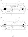
- Fig. 1 shows two embodiments of the pressure vessel 1 in lateral section (a) with floating flushing lance 5 and (b) as an embodiment according to the invention with flushing lance 5 attached to both ends 52, 53
- Middle part 21 with a cylinder axis ZA and with two pole caps 22a, 22b closing off the cylindrical middle part 21 to provide a storage volume SV in the pressure vessel.
- An outer layer for example an outer layer wound from fiber composite material, is applied to the inner container 2 for its mechanical reinforcement.
- the valve connection piece 4 for filling and emptying the storage volume SV with a filling gas FG with a desired degree of purity RG is arranged on one of the pole caps 22a, while the opposite pole cap 22b does not include such a connection.
- a hollow-shaped, outwardly open flushing lance 5 is passed through the valve connection piece 4 and held therein in a sealing manner with respect to the valve connection piece 4.
- This flushing lance 5 protrudes so far into the storage volume SV and is provided with a perforation 51 along its entire length L5 up to a first end 52 facing the pole cap 22b in the storage volume SV opposite the valve connector 4 for gas exchange with the storage volume.
- the flushing lance 5 extends so far to the opposite pole cap 22b that the gas exchange extends through the perforation 51 of the flushing lance 5 to the opposite pole cap 22b.
- the flushing lance 5 is made from a dimensionally stable material, for example from a plastic that is softer than the material of the inner container 2, at least in the area 5b within the storage volume SV.
- the material of the flushing lance 5 is, however, so stiff that when a gas filling GF of the storage volume SV is sucked off through the flushing lance 5, the latter remains dimensionally stable and does not collapse in its shape.
- the first end 52 of the flushing lance 5 is arranged floating freely in the storage volume SV of the pressure vessel 1 (not claimed).
- an additional weight 54 is additionally arranged at the first end 52 of the flushing lance 5.
- the term “at the first end” also denotes a surrounding area where the additional weight 54, for example a ball made of metal or lead, is attached here.
- the claimed embodiment is shown, wherein the first end 52 of the flushing lance 5 with the valve connection 4 opposite pole cap 22b is connected via a floating bearing 23, what Movements of the flushing lance 5 perpendicular to the cylinder axis ZA of the inner container 2 prevented. Nevertheless, the flushing lance 5 is movably and reversibly mounted parallel to the cylinder axis ZA of the inner container 2 in order to be able to compensate for changes in length of the pressure container 1 during pressure filling.
- the floating bearing 23 is designed here as a hollow sleeve with an inner diameter equal to the outer diameter of the flushing lance 5, the sleeve 23 including an insertion funnel 231 opening in the direction of the valve connection piece 4.
- the floating bearing 23 can be made of an expandable material.
- the flushing lance 5 is also reversibly connected to the valve connector 4 by suitable means (see also FIG Fig. 2 ).
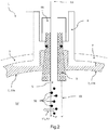
- Fig. 2 shows an embodiment of the pressure vessel 1 with flushing lance 5 in a detail view of the area of the pole cap 22a on the valve connector 4, which here is fastened to the pole cap 22a by means of a screw connection and seals against the inner container 2 by means of a sealing cone 6.
- the perforation 51 of the flushing lance 5 comprises gas inlet and gas outlet openings, the number, position and diameter of which are dimensioned so that both a thorough mixing of a gas filling GF in the storage volume SV and filling and emptying times of the storage volume SV with the filling gas FG are optimized.
- the circular perforations 51 shown here are only one example of possible perforations 5.
- the flushing lance can also comprise elongated, oval or differently shaped perforations 5.
- the spacing and the size of the perforations 5 can also vary depending on the embodiment.
- Fig. 3 shows an embodiment of the transport container 10 according to the invention, which here comprises, for example, five pressure containers 1 according to the invention, two of the pressure containers 1 containing freely floating flushing lances 5 and the other three pressure containers 1 containing flushing lances 5 fixed on both sides.
- the storage volumes SV of the pressure vessels 1 are via a common closable pipe system 11 via the respective valve connection pieces 4 and a respective second end 53 of the Flushing lances 5 connected to one another, the pipe system 11 also being connected to a device 12 for filling the pressure vessel 1 with the filling gas and for pumping out the gas filling in the pressure vessel 1.
- Such a device 12 in the transport container 10 makes it possible to reduce the effort of flushing and to lower the gas consumption in order to achieve the desired degree of purity RG.
- State-of-the-art hydrogen transport containers are purged at least 3 - 6 times (depending on the desired degree of purity of the filling gas) in order to remove the empty nitrogen transport gas before the next filling.
- the amount of hydrogen consumed per flush is EUR 7000. Flushing it five times therefore consumes 35,000 EUR of hydrogen. Including the increased amount of work, the total costs for washing five times are around EUR 50,000.
- Fig. 4 shows an embodiment of the method 100 according to the invention for filling the pressure vessel 1 according to the invention (see also FIG Fig. 1 and 2 ) with a filling gas FG with a desired degree of purity RG in the pressure vessel 1, comprising the following steps of filling 110 the pressure vessel 1 with the filling gas FG for a gas exchange with the storage volume SP through the flushing lance 5, which protrudes into the storage volume SV and along its entire length Length L5 up to a first end 52 of the flushing lance 5 facing the pole cap 22b opposite the valve connection piece 4 is provided with a perforation 51 in the storage volume SV; of carrying out 120 the gas exchange up to the opposite pole cap 22b, in that the flushing lance 5 extends suitably far to the pole cap 22b opposite the valve connection piece 4; subsequent pumping 130 the appropriately mixed gas filling GF in the pressure vessel 1 by means of a suitable device 12 through the flushing lance 5 to the outside of the pressure vessel; and repeating 140 the previous steps until the gas filling
- the gas composition of the pumped-out gas filling can expediently be measured here. If this has the desired degree of purity, the pressure vessel 1 then only needs to be filled once with the filling gas in order to reliably fill the storage volume with filling gas with the desired degree of purity. The filling process 100 then stops 150, since the desired degree of purity RG has been reached.
- Fig. 5 shows an embodiment of the method 200 according to the invention for producing the pressure vessel 1 according to the invention comprising the following steps of providing 210 a pressure vessel as in FIG Fig. 1 shown without flushing lance 5, the passage 220 of a hollow-shaped, outwardly open flushing lance 5 through the valve connector 4, the flushing lance 5 being designed to protrude into the storage volume SV and facing along its entire length L5 up to a first end 52 of the flushing lance 5 to the pole cap 22b opposite the valve connection piece 4 in the storage volume SV is provided with a perforation 51 for gas exchange with the storage volume, the flushing lance 5 extending to the pole cap 22b opposite the valve connecting piece 4 so that the gas exchange extends through the perforation 51 of the flushing lance 5 extends to the opposite pole cap 22b; and the fixing 230 of the flushing lance 5 on the valve connection piece 4 so that it is held by the valve connection piece 4 in a sealing manner with respect to the valve connection piece 4.
Landscapes
- Engineering & Computer Science (AREA)
- Mechanical Engineering (AREA)
- General Engineering & Computer Science (AREA)
- Filling Or Discharging Of Gas Storage Vessels (AREA)
Description
- Die Erfindung betrifft einen Druckbehälter mit Spüllanze, einen Transportcontainer mit solchen Druckbehältern sowie ein Verfahren zur Befüllung dieses Druckbehälters und ein Verfahren zur Herstellung des Druckbehälters.
- Der Markt für Druckbehälter, die mit Faserverbundmaterial verstärkt werden, wächst kontinuierlich. Die zunehmende Förderung von Erdgas und Fracking-Gas macht speziell in Ländern ohne entsprechendes Pipelinenetz eine Speicherung in Druckbehältern erforderlich. Hinzu kommt der Automobilsektor, der stark an der Entwicklung von Brennstoffzellen-Fahrzeugen arbeitet, bei denen der Brennstoff in Form von gasförmigem Wasserstoff unter hohem Druck in Druckbehältern gespeichert werden soll. Für den Transport der Druckbehälter sind leichte Druckbehälter gewünscht, da ein Transport von Druckbehältern mit hohen Behältergewichten unnötig viel Energie verbraucht und daher zu hohe Transportkosen verursacht.
- Gegenwärtig benutzte zylinderförmige Druckbehälter besitzen eine Verstärkungsschicht aus Faserverbundmaterial aus Fasern eingebettet in einem Matrixmaterial, die als Außenschicht mittels eines Wickelverfahrens auf einen Innenbehälter (der sogenannte Liner) des Druckbehälters, der als Wickelkern fungiert, aufgewickelt wird. Während der Innenbehälter beispielsweise die Gasdichtigkeit des Druckbehälters garantiert, verleiht die Verstärkungsschicht aus Faserverbundmaterial dem Druckbehälter die notwendige mechanische Stabilität. Bei den Druckbehältern des Typs 3 wird ein mechanischer Innenbehälter (metallischer Liner) z.B. aus Aluminium oder Stahl eingesetzt, bei Druckbehältern des Typs 4 ist der Innenbehälter (Liner) aus Kunststoff.
- Die Offenlegungsschrift
US 2015 / 345 708 A1 beschreibt ein Verfahren zum Befüllen von Kraftstofftanks, insbesondere von CNG-Kraftstofftanks. Das verbessert die Wärmeabgabe, wenn der Kraftstofftank bei einer Temperatur gefüllt wird, die niedriger ist als die ohne das Verfahren. Die Drucksensorlogik an einer Tankstelle ist weniger anfällig für Fehler bei der Messung der Kraftstoffmasse im Tank, sodass der Tank genauer und vollständiger gefüllt werden kann. Um die Wärmeabgabe zu verbessern, kann der Kraftstofftank mit einer Wärmesenke versehen sein, um die Wärmeübertragung vom Inneren des Kraftstofftanks zum Äußeren passiv zu erleichtern. Alternativ oder in Kombination kann der Kraftstofftank mit einem Kraftstoffströmungskanal versehen sein, durch den Kraftstoff aus dem Kraftstofftankinneren zirkuliert. Der Kraftstoffströmungskanal kann aktiv mit einem Lüfter oder einem Wasserkühlsystem gekühlt werden. - Druckbehälter werden mit Füllgas gefüllt, das einen gewünschten Reinheitsgrad haben soll. Da verbrauchte Druckbehälter in der Regel mit einem Transportgas (beispielsweise Stickstoff) unterschiedlich vom vorgesehenen Füllgas (beispielsweise Wasserstoff) zum Rücktransport gefüllt werden oder abwechselnd je nach Anforderung mit unterschiedlichen Füllgasen gefüllt werden sollen, müssen die Druckbehälter vor dem Befüllen mit dem vorgesehenen Füllgas vielmals gespült werden, damit das einzufüllende Füllgas mit dem gewünschten Reinheitsgrad (beispielsweise reiner als 99,9% oder reiner als 99,999%) in den Druckbehälter eingefüllt werden kann. Die Spülprozeduren zur Erlangung des kundenseitig definierten Reinheitsgrades sind aufwendig und teuer, da das Spülen des Druckbehälters mit dem Füllgas vorgenommen werden muss und gegebenenfalls eine Vielzahl an Befüllungen mit Füllgas vorgenommen werden müssen, um zum spezifizierten Reinheitsgrad zu kommen. Die Befüllungen vor Erreichung des spezifizierten Reinheitsgrades sind somit verbrauchte Gasmischungen und damit Abfall.
- Es ist daher wünschenswert, einen Druckbehälter und ein entsprechendes Befüllverfahren zur Verfügung zu haben, mit dem der Aufwand der Spülung vermindert und der Gasverbrauch zur Erlangung des gewünschten Reinheitsgrades gesenkt werden kann.
- Es ist eine Aufgabe der vorliegenden Erfindung, einen Druckbehälter und ein entsprechendes Befüllverfahren bereitzustellen, mit dem der Aufwand der Spülung vermindert und der Gasverbrauch zur Erlangung des gewünschten Reinheitsgrades gesenkt werden kann.
- Diese Aufgabe wird gelöst durch einen Druckbehälter umfassend einen Innenbehälter aus einem Innenbehältermaterial mit einem zylindrischen Mittelteil mit einer Zylinderachse und mit zwei das zylindrische Mittelteil abschließenden Polkappen zur Bereitstellung eines Speichervolumens im Druckbehälter, eine auf den Innenbehälter zu dessen Verstärkung aufgebrachte Außenschicht, ein Ventilanschlussstück angeordnet auf einer der Polkappen zur Befüllung und Entleerung des Speichervolumens mit einem Füllgas mit einem gewünschten Reinheitsgrad und eine hohlförmige nach außen offene Spüllanze, die durch das Ventilanschlussstück hindurchgeführt und darin gegenüber dem Ventilanschlussstück abdichtend gehalten ist, wobei die Spüllanze in das Speichervolumen hineinragt und entlang ihrer gesamten Länge bis zu einem ersten Ende der Spüllanze zugewandt zu der dem Ventilanschlussstück gegenüberliegenden Polkappe im Speichervolumen für einen Gasaustausch mit dem Speichervolumen mit einer Perforation versehen ist, wobei sich die Spüllanze soweit zu der dem Ventilanschlussstück gegenüberliegenden Polkappe erstreckt, dass sich der Gasaustausch durch die Perforation der Spüllanze hindurch bis zur gegenüberliegenden Polkappe erstreckt, wobei dass das erste Ende der Spüllanze mit der dem Ventilanschluss gegenüberliegenden Polkappe geeignet verbunden ist und wobei die gegenüberliegende Polkappe ein geeignet ausgeführtes Loslager zur Fixierung der Spüllanze gegen Bewegungen senkrecht zur Zylinderachse (ZA) des Innenbehälters umfasst, in dem die Spüllanze dennoch parallel zur Zylinderachse (ZA) des Innenbehälters beweglich reversibel gelagert ist.
- Der Druckbehälter kann dabei für Füllgase aller Art verwendet werden, vorzugsweise wird der Druckbehälter für leicht flüchtige Gase wie Wasserstoff verwendet. Der Innenbehälter kann dabei aus einem Innenbehältermaterial vorzugsweise Kunststoff, beispielsweise PE, PA, PP hergestellt sein. Diese Materialien bieten eine sehr geringe Gaspermeabilität für beispielsweise Wasserstoff. Die Außenschicht kann ebenfalls aus jedem dafür geeigneten Material hergestellt sein. Bei einer Außenschicht aus Faserverbundmaterial besteht dieses aus Fasern eingebettet in einem Matrixmaterial zur Bereitstellung einer besonders hohen mechanischen Belastbarkeit der Außenschicht des Druckbehälters. Somit wird die Funktionalität der Gasdichtigkeit durch den Innenbehälter und die mechanische Belastbarkeit durch die Außenschicht für den Druckbehälter bereitgestellt. Die Spüllanze kann dauerstabil oder demontierbar mit dem Ventilanschlussstück verbunden sein. Die Perforation der Spüllanze ermöglicht ein über die gesamte Länge des Druckbehälters homogenes Einströmen des Füllgases und sorgt für ausreichende Durchmischung des Füllgases mit der bereits vorhandenen Gasfüllung im Druckbehälter. Auf diese Weise wird verhindert, dass sich im Druckbehälter bei der Befüllung eine Zone geringer oder gar fehlender Durchmischung ausbilden kann. Eine solche Zone bildet sich dann aus, wenn die bei der Befüllung vorhandene Gasfüllung nicht durch ein zweites Ventil (wie am erfindungsgemäßen Druckbehälter eben nicht vorhanden) am gegenüberliegenden Ende entweichen kann.
- Die Spüllanze kann aus jedem geeigneten Material hergestellt sein, dass einerseits mit einer Perforation für einen Gasaustausch aus der Spüllanze heraus beziehungsweise in die Spüllanze herein versehen werden kannund andererseits die Temperaturbelastung durch die mehrfache Befüllung mit hohem Druck ohne Schäden überstehen kann, beispielsweise EPP. Die Temperaturbelastung im erfindungsgemäßen Druckbehälter beträgt durch die gute Gasdurchmischung und der damit verbundenen besonders hohen Konvektion weniger als 160°C bei einer Befüllung mit 500bar. Gewöhnliche Druckbehälter ohne Spüllanze erreichen dagegen Temperaturen von bis zu 300°C. Die voranstehenden Temperaturen beziehen sich auf lokale Temperaturmaxima im Gas. Die Spülbarkeit des Speichervolumens wird durch das Vorhandensein der erfindungsgemäßen Spüllanze drastisch verbessert, da die Umwälzung der Gasfüllung im Druckbehälter durch die Ausdehnung des Volumens mit direktem Gasaustausch aufgrund der Perforation der Spüllanze in Verbindung mit einer weit in das Speichervolumen hereinragende Spüllanze so ausgedehnt wird, dass alle Bereiche des Speichervolumens einschließlich des Bereichs direkt an der gegenüberliegenden Polkappe am Gasaustausch teilnehmen. Dadurch kann die Anzahl der für den gewünschten Reinheitsgrad des Füllgases im Druckbehälter benötigten Befüll- und Entleerungszyklen selbst bei hohen Reinheitsgraden auf gegebenenfalls weniger als drei reduziert werden. Bei niedrigen Reinheitsgraden werden gegenwärtige Druckbehälter nach dem Stand der Technik mindestens dreimal, bei hohen gewünschten Reinheitsgraden mindestens fünfmal gespült. Die Kostenersparnis für beispielsweise Wasserstoff als Füllgas ist beträchtlich. Die eingesparte Prozesszeit bei der Befüllung der Druckbehälter trägt zusätzlich zur Kosteneinsparung bei.
- Der erfindungsgemäße Druckbehälter ermöglicht es somit, den Aufwand der Spülung zu vermindern und den Gasverbrauch zur Erlangung des gewünschten Reinheitsgrades zu senken.
- Das erste Ende der Spüllanze ist mit der dem Ventilanschluss gegenüberliegenden Polkappe geeignet verbunden. Damit ist die Spüllanze im Speichervolumen beidseitig fixiert, sodass Stöße gegen den Druckbehälter nicht mehr dazu führen können, dass die Spüllanze gegen den Innenbehälter schlägt und diesen beschädigen kann. Dadurch kann der Druckbehälter in jeder Position transportiert werden, ohne dass dadurch ein Risiko besteht, dass die Spüllanze während des Transports innen gegen den Innenbehälter schlagen kann.
- Die gegenüberliegende Polkappe umfasst ein geeignet ausgeführtes Loslager zur Fixierung der Spüllanze gegen Bewegungen senkrecht zur Zylinderachse des Innenbehälters, in dem die Spüllanze dennoch parallel zur Zylinderachse des Innenbehälters beweglich reversibel gelagert ist. Das Loslager stellt eine Führung dar, in der die Spüllanze eingeführt und gehalten wird, ohne dass die Spüllanze darin in ihrer Längsrichtung (Richtung entlang der Zylinderachse des Innenbehälters) fest fixiert ist. Dadurch wird die Spüllanze selbst bei Längenänderungen des Druckbehälters aufgrund der Druckbefüllung ohne Spannungen in ihrer Längsrichtung so gelagert, dass die Spüllanze senkrecht zu Längsrichtung keine Bewegungen ausführen kann und somit nicht den Innenbehälter dadurch beschädigen kann. Das Loslager kann jede für diesen Zweck geeignete Form besitzen. Das Material des Loslagers ist vorzugsweise dasselbe Material wie das des Innenbehälters.
- In einer Ausführungsform ist die Spüllanze zumindest in dem Bereich innerhalb des Speichervolumens aus einem formstabilen Material gefertigt. Die Formstabilität erleichtert das Einführen der Spüllanze in das Speichervolumen und verhindert eine Beschädigung des Innenbehälters beim Einführen der Lanze durch Entlangkratzen an der Innenseite des Innenbehälters.
- In einer weiteren Ausführungsform ist das formstabile Material ein Kunststoff, der weicher als das Material des Innenbehälters. Der Begriff "weicher" bezieht sich dabei den Härtegrad eines Materials. Je weniger hart ein Material ist, desto weicher ist es. Beispielsweise für Kunststoffmaterialien für Innenbehälter und Lanze ist es vorteilhaft, wenn das Lanzenmaterial einen geringeren Shore-Wert als das Material des Innenbehälters besitzt, wobei Shore-A weiche Materialien und Shore-D dazu vergleichsweise härtere Materialien bezeichnet. PE-LD-Material besitzt einen Härte Shore-D, während beispielsweise Gummi eine Härte Shore-A besitzt. Insofern wäre eine Lanze aus Gummi in einem Innenbehälter aus PE-LD konform mit obiger Ausführungsform. Dadurch werden Beschädigungen des Innenbehälters bei freihängenden Lanzen oder beim Einführen von Lanzen im Falle von Berührungen der Innenseite des Innenbehälters durch die Spüllanze verhindert. Gegenüber metallischen Lanzen besteht der weitere Vorteil, dass diese bei Anschluss an eine Rohrverbindung in einem Transportcontainer oftmals materialbedingt einen Ermüdungsbruch erleiden, sodass die Lanze in den Druckbehälter fällt und den Innenbehälter beschädigt. Außerdem ist die abgebrochene Lanze nur schwer wieder aus dem Behälter zu entfernen. Diese Nachteile werden mit einem Spüllanze aus einem Kunststoffmaterial vermieden.
- In einer weiteren Ausführungsform ist das Loslager als hohle Hülse mit einem Innendurchmesser gleich oder größer als ein Außendurchmesser der Spüllanze zumindest im Bereich der gegenüberliegenden Polkappe ausgestaltet, wobei die Hülse einen sich in Richtung des Ventilanschlussstücks öffnenden Einführtrichter umfasst. Dieses Loslager ist einfach zu fertigen und die Spüllanze leicht in die Hülse als Loslager einzuführen, wobei der Einführtrichter die Einführung erleichtert, da er selbst bei Abweichungen der Spüllanze von der Zylinderachse das erste Ende sicher aufnehmen kann.
- In einer weiteren Ausführungsform ist das Loslager aus einem dehnfähigen Material gefertigt. Dadurch wird das erste Ende gegen einen gewissen Widerstand in das Loslager eingeführt, indem die Spüllanze das Loslager leicht dehnen muss, sofern der Innendurchmesser des Loslagers kleiner ist als der Außendurchmesser der Spüllanze, was zu einem festeren Sitz der Spüllanze in dem Loslager führt. Sind die Größenverhältnisse anders herum, so dämpft zumindest das dehnfähige Material die Weiterleitung etwaige Stöße auf den Druckbehälter zu der Spüllanze.
- In einer weiteren Ausführungsform ist die Spüllanze über geeignete Mittel reversibel mit dem Ventilanschlussstück verbunden, was das Entfernen der Spüllanze bei Bedarf ermöglicht, beispielsweise zu Wartungszwecken.
- In einer weiteren Ausführungsform ist das Material der Spüllanze so steif, dass beim Absaugen einer Gasfüllung des Speichervolumens durch die Spüllanze hindurch diese formstabil bleibt und nicht in ihrer Form kollabiert. Dies ermöglicht zuverlässige Mehrfachzyklen von Befüllung und Entleerung zur Herstellung einer gewünschten Gasreinheit bei der Befüllung des Speichervolumens ohne Beeinträchtigung des Gasstroms des ausströmenden Gases beim Abpumpen der Gasfüllung.
- Einer weiteren Ausführungsform umfasst die Perforation der Spüllanze Gaseinlass- und Gasauslassöffnungen, deren Anzahl, Position und Durchmesser so dimensioniert sind, dass sowohl eine Durchmischung einer Gasfüllung im Speichervolumen als auch Befüllungs- und Entleerungszeiten des Speichervolumens mit dem Füllgas optimiert sind. Hierbei können die Durchmesser der Öffnungen, Löcher oder Schlitze als Perforation und deren Abstände zueinander variieren. Die Perforation sollte ferner so gestaltet sein, dass geforderte Befüllungszeiten und Flussgeschwindigkeiten des Füllgases beziehungsweise der Gasfüllung durch die Spüllanze ermöglicht werden. Eine größere Menge an Einlass- und Auslassöffnungen (wobei die Gaseinlassöffnungen selbst auch die Gasauslassöffnungen darstellen können) verringert die Befüllungs- und Entleerungszeiten, gerade eine größere Anzahl dieser Öffnungen im Bereich des ersten Endes erhöht die Gasdurchmischung im Bereich der gegenüberliegenden Polkappe, wodurch das "untere" Gas durch die Befüllung durch das Speichervolumen geströmt wird.
- Die Erfindung betrifft des Weiteren einen Transportcontainer umfassend eine Vielzahl an erfindungsgemäßen Druckbehältern, deren Speichervolumina über ein gemeinsames verschließbares Rohrsystem über die jeweiligen Ventilanschlussstücke und einem jeweiligen zweiten Ende der Spüllanze miteinander verbunden sind. Druckbehälter werden gewöhnlich in einer entsprechenden Transporteinheit, hier ein Container, unter Verbindung der einzelnen Speichervolumina transportiert. Dabei kann der Gasinhalt der Container über das Rohrsystem kontrolliert werden. Die Druckbehälter werden in der vom Container vorgesehenen Transportausrichtung transportiert, hier beispielsweise in einer vertikalen Ausrichtung, wo aus Sicherheitsgründen die Ventilanschlüsse vorzugsweise auf der Oberseite angeordnet sind, sodass die Spüllanze sich von Ventilanschlussstück vertikal nach unten in den Druckbehälter erstreckt.
- Der erfindungsgemäße Transportcontainer ermöglicht es somit, den Aufwand der Spülung zu vermindern und den Gasverbrauch zur Erlangung des gewünschten Reinheitsgrades zu senken.
- In einer Ausführungsform ist das Rohrsystem dazu mit einer Vorrichtung zur Befüllung der Druckbehälter mit dem Füllgas und zum Abpumpen der Gasfüllung in den Druckbehältern verbunden. Dadurch kann die Transportzeit oder Standzeit im Container genutzt werden, um das Speichervolumen zu spülen. Die Vorrichtung kann beispielsweise eine Kombination aus einer Pumpvorrichtung und einer Gaseinlassvorrichtung für einen externen Gastank oder Gaszuleitung sein.
- Die Erfindung betrifft des Weiteren ein Verfahren zum Befüllen eines erfindungsgemäßen Druckbehälters mit einem Füllgas mit einem gewünschten Reinheitsgrad im Druckbehälter, der einen Innenbehälter aus einem Innenbehältermaterial mit einem zylindrischen Mittelteil mit einer Zylinderachse und mit zwei das zylindrischen Mittelteil abschließenden Polkappen zur Bereitstellung eines Speichervolumens im Druckbehälter, eine auf den Innenbehälter zu dessen Verstärkung aufgebrachte Außenschicht, ein Ventilanschlussstück angeordnet auf einer der Polkappen und eine hohlförmige nach außen offene durch das Ventilanschlussstück hindurchgeführte und darin gegenüber dem Ventilanschlussstück abdichtend gehaltene Spüllanze umfasst, umfassend die nachfolgenden Schritte:
- Befüllen des Druckbehälters mit dem Füllgas für einen Gasaustausch mit dem Speichervolumen durch die Spüllanze, die in das Speichervolumen hineinragt und entlang ihrer gesamten Länge bis zu einem ersten Ende der Spüllanze zugewandt zu der dem Ventilanschlussstück gegenüberliegenden Polkappe im Speichervolumen mit einer Perforation versehen ist;
- Ausführen des Gasaustausches bis zur gegenüberliegenden Polkappe, indem sich die Spüllanze dafür geeignet weit zu der dem Ventilanschlussstück gegenüberliegenden Polkappe erstreckt;
- nachfolgendes Abpumpen der entsprechend durchmischten Gasfüllung im Druckbehälter mittels einer geeigneten Vorrichtung durch die Spüllanze hindurch nach außerhalb des Druckbehälters; und
- Wiederholen der vorangegangenen Schritte bis die Gasfüllung im Druckbehälter dem Füllgas mit dem gewünschten Reinheitsgrad entspricht.
- Die Gaszusammensetzung der Gasfüllung kann dabei beim Abpumpen durch eine entsprechende Analysevorrichtung gemessen werden, um zu bestimmen, ob ein weiterer Befüllungs- und Abpumpzyklus für den gewünschten Reinheitsgrad durchlaufen werden muss. Auf die Gasanalyse kann verzichtet werden, wenn ausreichend Erfahrung mit der Befüll- und Abpumpprozedur besteht, sodass sich der Reinheitsgrad alleine aus der Anzahl der Befüll- und Abpumpzyklen ergibt.
- Das erfindungsgemäße Verfahren ermöglicht es somit, den Aufwand der Spülung zu vermindern und den Gasverbrauch zur Erlangung des gewünschten Reinheitsgrades zu senken.
- Die Erfindung betrifft des Weiteren ein Verfahren zur Herstellung eines erfindungsgemäßen Druckbehälters umfassend die nachfolgenden Schritte:
- Bereitstellen eines Innenbehälters aus einem Innenbehältermaterial mit einem zylindrischen Mittelteil mit einer Zylinderachse und mit zwei das zylindrische Mittelteil abschließenden Polkappen zur Bereitstellung eines Speichervolumens, der zu dessen Verstärkung eine darauf aufgebrachte Außenschicht umfasst, wobei ein Ventilanschlussstück auf einer der Polkappen zur Aufnahme eines Ventils zum Verschließen des Speichervolumens umfasst;
- Hindurchführen einer hohlförmigen nach außen offenen Spüllanze durch das Ventilanschlussstück hindurch, wobei die Spüllanze dazu ausgestaltet ist, in das Speichervolumen hineinzuragen und entlang ihrer gesamten Länge bis zu einem ersten Ende der Spüllanze zugewandt zu der dem Ventilanschlussstück gegenüberliegenden Polkappe im Speichervolumen für einen Gasaustausch mit dem Speichervolumen mit einer Perforation versehen ist, wobei sich die Spüllanze soweit zu der dem Ventilanschlussstück gegenüberliegenden Polkappe erstreckt, dass sich der Gasaustausch durch die Perforation der Spüllanze hindurch bis zur gegenüberliegenden Polkappe erstreckt; und
- Fixieren der Spüllanze am Ventilanschlussstück, damit diese vom Ventilanschlussstück abdichtend gegenüber dem Ventilanschlussstück gehalten wird.
- Das erfindungsgemäße Verfahren ermöglicht es somit, einen Druckbehälter herzustellen, mit dem der Aufwand der Spülung vermindert und der Gasverbrauch zur Erlangung des gewünschten Reinheitsgrades gesenkt werden kann.
- Diese und andere Aspekte der Erfindung werden im Detail in den Abbildungen wie folgt gezeigt.
- Fig.1:
- zwei Ausführungsformen des erfindungsgemäßen Druckbehälters im seitlichen Schnitt (a) mit freischwebender Spüllanze und (b) mit Spüllanze befestigt an beiden Enden;
- Fig.2:
- eine Ausführungsform des Druckbehälters mit Spüllanze in einer Ausschnittdarstellung;
- Fig.3:
- eine Ausführungsform des erfindungsgemäßen Transportcontainers;
- Fig.4:
- eine Ausführungsform des erfindungsgemäßen Verfahrens zum Befüllen des erfindungsgemäßen Druckbehälters;
- Fig.5:
- eine Ausführungsform des erfindungsgemäßen Verfahrens zur Herstellung des erfindungsgemäßen Druckbehälters.
-
Fig.1 zeigt zwei Ausführungsformen des Druckbehälters 1 im seitlichen Schnitt (a) mit freischwebender Spüllanze 5 und (b) als erfindungsgemäße Ausführungsform mit Spüllanze 5 befestigt an beiden Enden 52, 53. Der Druckbehälter 1 umfasst einen Innenbehälter 2 aus einem Innenbehältermaterial mit einem zylindrischen Mittelteil 21 mit einer Zylinderachse ZA und mit zwei das zylindrische Mittelteil 21 abschließenden Polkappen 22a, 22b zur Bereitstellung eines Speichervolumens SV im Druckbehälter. Auf den Innenbehälter 2 ist zu dessen mechanischer Verstärkung eine Außenschicht 3 aufgebracht, beispielsweise eine aus Faserverbundmaterial gewickelte Außenschicht. Das Ventilanschlussstück 4 zur Befüllung und Entleerung des Speichervolumens SV mit einem Füllgas FG mit einem gewünschten Reinheitsgrad RG ist auf einer der Polkappen 22a angeordnet, während die gegenüberliegende Polkappe 22b keinen solchen Anschluss umfasst. Da das Ventilanschlussstück 4 eine Verbindung in das Speichervolumen SV bereitstellt, ist eine hohlförmige nach außen offene Spüllanze 5 durch das Ventilanschlussstück 4 hindurchgeführt und darin gegenüber dem Ventilanschlussstück 4 abdichtend gehalten. Diese Spüllanze 5 ragt in das Speichervolumen SV soweit hineinragt und ist entlang ihrer gesamten Länge L5 bis zu einem ersten Ende 52 zugewandt zu der dem Ventilanschlussstück 4 gegenüberliegenden Polkappe 22b im Speichervolumen SV für einen Gasaustausch mit dem Speichervolumen mit einer Perforation 51 versehen. Die Spüllanze 5 erstreckt sich dabei soweit zur gegenüberliegenden Polkappe 22b, dass sich der Gasaustausch durch die Perforation 51 der Spüllanze 5 hindurch bis zur gegenüberliegenden Polkappe 22b erstreckt. Die Spüllanze 5 ist dabei zumindest in dem Bereich 5b innerhalb des Speichervolumens SV aus einem formstabilen Material gefertigt, beispielsweise aus einem Kunststoff, der weicher als das Material des Innenbehälters 2 ist. Das Material der Spüllanze 5 ist allerdings so steif, dass beim Absaugen einer Gasfüllung GF des Speichervolumens SV durch die Spüllanze 5 hindurch diese formstabil bleibt und nicht in ihrer Form kollabiert. InFig.1a ist das erste Ende 52 der Spüllanze 5 freischwebend im Speichervolumen SV des Druckbehälters 1 angeordnet (nicht beansprucht). In dieser Ausführungsform ist am ersten Ende 52 der Spüllanze 5 zusätzlich ein Zusatzgewicht 54 angeordnet. Der Begriff "am ersten Ende" bezeichnet dabei neben dem ersten Ende 52 auch einen umgebenden Bereich, wo hier das Zusatzgewicht 54, beispielsweise eine Kugel aus Metall oder Blei befestigt ist. InFig. 1b ist die beanspruchte Ausführungsform dargestellt, wobei das erste Ende 52 der Spüllanze 5 mit der dem Ventilanschluss 4 gegenüberliegenden Polkappe 22b über ein Loslager 23 verbunden ist, was Bewegungen der Spüllanze 5 senkrecht zur Zylinderachse ZA des Innenbehälters 2 verhindert. Trotzdem ist die Spüllanze 5 parallel zur Zylinderachse ZA des Innenbehälters 2 beweglich reversibel gelagert, um Längenveränderungen des Druckbehälters 1 bei der Druckbefüllung ausgleichen zu können. Das Loslager 23 ist hier als hohle Hülse mit einem Innendurchmesser gleich dem Außendurchmesser der Spüllanze 5 ausgestaltet, wobei die Hülse 23 einen sich in Richtung des Ventilanschlussstücks 4 öffnenden Einführtrichter 231 umfasst. Das Loslager 23 kann aus einem dehnfähigen Material gefertigt sein. Die Spüllanze 5 ist ferner über geeignete Mittel reversibel mit dem Ventilanschlussstück 4 verbunden (siehe dazu auchFig.2 ). -
Fig.2 zeigt eine Ausführungsform des Druckbehälters 1 mit Spüllanze 5 in einer Ausschnittdarstellung des Bereichs der Polkappe 22a am Ventilanschlussstück 4, das hier mittels einer Schraubverbindung auf die Polkappe 22a befestigt ist und mittels eines Dichtkonus 6 gegenüber dem Innenbehälter 2 abdichtet. Dieser ist zur Verstärkung mit einer Außenschicht 3 versehen. Die Perforation 51 der Spüllanze 5 umfasst Gaseinlass- und Gasauslassöffnungen, deren Anzahl, Position und Durchmesser so dimensioniert sind, dass sowohl eine Durchmischung einer Gasfüllung GF im Speichervolumen SV als auch Befüllungs- und Entleerungszeiten des Speichervolumens SV mit dem Füllgas FG optimiert sind. Die hier gezeigten kreisförmigen Perforierungen 51 sind nur ein Beispiel für mögliche Perforierungen 5. In anderen Ausführungsformen kann die Spüllanze auch längliche, ovale oder anders geformte Perforierungen 5 umfassen. Auch kann der Abstand und die Größe der Perforierungen 5 je nach Ausführungsform variieren. -
Fig.3 zeigt eine Ausführungsform des erfindungsgemäßen Transportcontainers 10, der hier beispielsweise fünf erfindungsgemäße Druckbehältern 1 umfasst, wobei zwei der Druckbehälter 1 freischwebende Spüllanzen 5 und die anderen drei Druckbehälter 1 beidseitig fixierte Spüllanzen 5 enthalten. Zu den Details der Druckbehälter 1 wird aufFig.1 verwiesen. Die Speichervolumina SV der Druckbehälter 1 sind über ein gemeinsames verschließbares Rohrsystem 11 über die jeweiligen Ventilanschlussstücke 4 und einem jeweiligen zweiten Ende 53 der Spüllanzen 5 miteinander verbunden, wobei das Rohrsystem 11 außerdem mit einer Vorrichtung 12 zur Befüllung der Druckbehälter 1 mit dem Füllgas und zum Abpumpen der Gasfüllung in den Druckbehältern 1 verbunden ist. Eine solche Vorrichtung 12 im Transportcontainer 10 ermöglicht es, den Aufwand der Spülung zu vermindern und den Gasverbrauch zur Erlangung des gewünschten Reinheitsgrades RG zu senken. Wasserstoff-Transportcontainer nach dem Stand der Technik werden mindestens 3 ― 6 Mal gespült (abhängig vom gewünschten Reinheitsgrad des Füllgases), um das Leer-Transportgas Stickstoff vor der nächsten Befüllung wieder zu entfernen. Bei einer angenommenen Speicherkapazität eines 40-Fuß-Containers von 1000kg Wasserstoff und einem Wasserstoffpreis von 7 EUR/kg ergibt sich pro Spülen ein Betrag von verbrauchtem Wasserstoff in Höhe von 7000 EUR. Ein fünfmaliges Spülen verbraucht somit Wasserstoff in Höhe von 35.000 EUR. Inklusive des erhöhten Arbeitsaufwands liegen die Spülkosten bei fünfmaligem Spülen insgesamt bei ca. 50.000 EUR. Mit dem erfindungsgemäßen Druckbehälter 1 können aufgrund der Spüllanze 5 die Hälfte der Spülkosten eingespart werden. Für eine Reinheit 5.0 (entspricht einer Reinheit von 99,999%) benötigt man mit dem erfindungsgemäßen Druckbehälter 1 nur drei Spülungen, während Druckbehälter nach dem Stand der Technik dafür sechs oder mehr Spülungen benötigen. -
Fig.4 zeigt eine Ausführungsform des erfindungsgemäßen Verfahrens 100 zum Befüllen des erfindungsgemäßen Druckbehälters 1 (siehe dazu auchFig.1 und2 ) mit einem Füllgas FG mit einem gewünschten Reinheitsgrad RG im Druckbehälter 1, umfassend die nachfolgenden Schritte des Befüllens 110 des Druckbehälters 1 mit dem Füllgas FG für einen Gasaustausch mit dem Speichervolumen SP durch die Spüllanze 5, die in das Speichervolumen SV hineinragt und entlang ihrer gesamten Länge L5 bis zu einem ersten Ende 52 der Spüllanze 5 zugewandt zur dem Ventilanschlussstück 4 gegenüberliegenden Polkappe 22b im Speichervolumen SV mit einer Perforation 51 versehen ist; des Ausführens 120 des Gasaustausches bis zur gegenüberliegenden Polkappe 22b, indem sich die Spüllanze 5 dafür geeignet weit zu der dem Ventilanschlussstück 4 gegenüberliegenden Polkappe 22b erstreckt; des nachfolgenden Abpumpens 130 der entsprechend durchmischten Gasfüllung GF im Druckbehälter 1 mittels einer geeigneten Vorrichtung 12 durch die Spüllanze 5 hindurch nach außerhalb des Druckbehälters; und des Wiederholens 140 der vorangegangenen Schritte bis die Gasfüllung GF im Druckbehälter dem Füllgas FG mit dem gewünschten Reinheitsgrad RG entspricht. Hierbei kann zweckmäßigerweise die Gaszusammensetzung der abgepumpten Gasfüllung gemessen werden. Sofern diese den gewünschten Reinheitsgrad aufweist, braucht danach der Druckbehälter 1 nur noch einmal mit dem Füllgas gefüllt werden, um das Speichervolumen sicher mit Füllgas mit gewünschtem Reinheitsgrad zu füllen. Danach stoppt 150 der Befüllprozess 100, da der gewünschte Reinheitsgrad RG erreicht ist. -
Fig.5 zeigt eine Ausführungsform des erfindungsgemäßen Verfahrens 200 zur Herstellung des erfindungsgemäßen Druckbehälters 1 umfassend die nachfolgenden Schritte des Bereitstellens 210 eines Druckbehälters wie inFig.1 gezeigt ohne Spüllanze 5, des Hindurchführens 220 einer hohlförmigen nach außen offenen Spüllanze 5 durch das Ventilanschlussstück 4 hindurch, wobei die Spüllanze 5 dazu ausgestaltet ist, in das Speichervolumen SV hineinzuragen und entlang ihrer gesamten Länge L5 bis zu einem ersten Ende 52 der Spüllanze 5 zugewandt zur dem Ventilanschlussstück 4 gegenüberliegenden Polkappe 22b im Speichervolumen SV für einen Gasaustausch mit dem Speichervolumen mit einer Perforation 51 versehen ist, wobei sich die Spüllanze 5 soweit zur dem Ventilanschlussstück 4 gegenüberliegenden Polkappe 22b erstreckt, dass sich der Gasaustausch durch die Perforation 51 der Spüllanze 5 hindurch bis zur gegenüberliegenden Polkappe 22b erstreckt; und des Fixierens 230 der Spüllanze 5 am Ventilanschlussstück 4, damit diese vom Ventilanschlussstück 4 abdichtend gegenüber dem Ventilanschlussstück 4 gehalten wird. Auf den so hergestellten Druckbehälter 1 kann nun das Verfahren gemäßFig.4 angewendet werden. - Die hier gezeigten Ausführungsformen stellen nur Beispiele für die vorliegende Erfindung dar und dürfen daher nicht einschränkend verstanden werden.
- Alternative durch den Fachmann in Erwägung gezogene Ausführungsformen sind gleichermaßen vom Schutzbereich der vorliegenden Ansprüche umfasst.
-
- 1
- Druckbehälter
- 2
- Innenbehälter
- 21
- zylindrisches Mittelteil
- 22a
- abschließende Polkappe auf Seiten des Ventilanschlussstücks
- 22b
- gegenüberliegende Polkappe
- 23
- Loslager auf der gegenüberliegenden Polkappe
- 231
- sich öffnender Einführtrichter
- 3
- Außenschicht aus Faserverbundmaterial
- 4
- Ventilanschlussstück
- 5
- Spüllanze
- 5b
- Bereich der Spüllanze im Speichervolumen
- 51
- Perforation
- 52
- erstes Ende der Spüllanze
- 53
- zweites Ende der Spüllanze
- 54
- Zusatzgewicht
- 55
- Mittel zur Befestigung der Spüllanze am Ventilanschlussstück
- 6
- Dichtkonus
- 10
- erfindungsgemäßer Transportcontainer
- 11
- Rohrsystem
- 12
- Vorrichtung zur Befüllung der Druckbehälter mit Füllgas und zum Abpumpen der Gasfüllung in den Druckbehältern
- 100
- Verfahren zum Befüllen eines erfindungsgemäßen Druckbehälters
- 110
- Befüllen des Druckbehälters mit dem Füllgas für einen Gasaustausch mit dem Speichervolumen
- 120
- Ausführen des Gasaustausches bis zur gegenüberliegenden Polkappe
- 130
- nachfolgendes Abpumpen der entsprechend durchmischten Gasfüllung
- 140
- Wiederholen der vorangegangenen Schritte
- 150
- Ende des Befüllungsverfahrens
- 200
- Verfahren zur Herstellung eines erfindungsgemäßen Druckbehälters
- 210
- Bereitstellen eines Druckbehälters ohne Spülllanze
- 220
- Hindurchführen einer Spüllanze durch das Ventilanschlussstück hindurch
- 230
- Fixieren der Spüllanze am Ventilanschlussstück
- FG
- Füllgas zur Füllung des Speichervolumens
- GF
- Gasfüllung des Speichervolumens
- L5
- Länge der Spüllanze im Speichervolumen
- RG
- gewünschter Reinheitsgrad der Gasfüllung im Druckbehälter
- SV
- Speichervolumen
- VR
- vertikale Richtung
- ZA
- Zylinderachse
Claims (12)
- Ein Druckbehälter (1) umfassend einen Innenbehälter (2) aus einem Innenbehältermaterial mit einem zylindrischen Mittelteil (21) mit einer Zylinderachse (ZA) und mit zwei das zylindrische Mittelteil (21) abschließenden Polkappen (22a, 22b) zur Bereitstellung eines Speichervolumens (SV) im Druckbehälter, eine auf den Innenbehälter (2) zu dessen Verstärkung aufgebrachte Außenschicht (3), ein Ventilanschlussstück (4) angeordnet auf einer der Polkappen (22a) zur Befüllung und Entleerung des Speichervolumens (SV) mit einem Füllgas (FG) mit einem gewünschten Reinheitsgrad (RG) und eine hohlförmige nach außen offene Spüllanze (5), die durch das Ventilanschlussstück (4) hindurchgeführt und darin gegenüber dem Ventilanschlussstück (4) abdichtend gehalten ist, wobei die Spüllanze (5) in das Speichervolumen (SV) hineinragt und entlang ihrer gesamten Länge (L5) bis zu einem ersten Ende (52) der Spüllanze (5) zugewandt zu der dem Ventilanschlussstück (4) gegenüberliegenden Polkappe (22b) im Speichervolumen (SV) für einen Gasaustausch mit dem Speichervolumen mit einer Perforation (51) versehen ist, wobei sich die Spüllanze (5) soweit zu der dem Ventilanschlussstück (4) gegenüberliegenden Polkappe (22b) erstreckt, dass sich der Gasaustausch durch die Perforation (51) der Spüllanze (5) hindurch bis zur gegenüberliegenden Polkappe (22b) erstreckt, dadurch gekennzeichnet, dass das erste Ende (52) der Spüllanze (5) mit der dem Ventilanschluss (4) gegenüberliegenden Polkappe (22b) geeignet verbunden ist, wobei die gegenüberliegende Polkappe (22b) ein geeignet ausgeführtes Loslager (23) zur Fixierung der Spüllanze (5) gegen Bewegungen senkrecht zur Zylinderachse (ZA) des Innenbehälters (2) umfasst, in dem die Spüllanze (5) dennoch parallel zur Zylinderachse (ZA) des Innenbehälters (2) beweglich reversibel gelagert ist.
- Der Druckbehälter (1) nach Anspruch 1,
dadurch gekennzeichnet,
dass die Spüllanze (5) zumindest in dem Bereich (5b) innerhalb des Speichervolumens (SV) aus einem formstabilen Material gefertigt ist. - Der Druckbehälter (1) nach Anspruch 2,
dadurch gekennzeichnet,
dass das formstabile Material ein Kunststoff ist, der weicher als das Material des Innenbehälters (2) ist. - Der Druckbehälter (1) nach einem der vorherigen Ansprüche,
dadurch gekennzeichnet,
dass das Loslager (23) als hohle Hülse mit einem Innendurchmesser gleich oder größer als ein Außendurchmesser der Spüllanze (5) zumindest im Bereich der gegenüberliegenden Polkappe (22b) ausgestaltet ist, wobei die Hülse (23) einen sich in Richtung des Ventilanschlussstücks (4) öffnenden Einführtrichter (231) umfasst. - Der Druckbehälter (1) nach einem der vorherigen Ansprüche,
dadurch gekennzeichnet,
dass das Loslager (23) aus einem dehnfähigen Material gefertigt ist. - Der Druckbehälter (1) nach einem der voranstehenden Ansprüche,
dadurch gekennzeichnet,
dass die Spüllanze (5) über geeignete Mittel reversibel mit dem Ventilanschlussstück (4) verbunden ist. - Der Druckbehälter (1) nach einem der voranstehenden Ansprüche,
dadurch gekennzeichnet,
dass das Material der Spüllanze (5) so steif ist, dass beim Absaugen einer Gasfüllung (GF) des Speichervolumens (SV) durch die Spüllanze (5) hindurch diese formstabil bleibt und nicht in ihrer Form kollabiert. - Der Druckbehälter (1) nach einem der voranstehenden Ansprüche,
dadurch gekennzeichnet,
dass die Perforation (51) der Spüllanze (5) Gaseinlass- und Gasauslassöffnungen (511) umfasst, deren Anzahl, Position und Durchmesser so dimensioniert sind, dass sowohl eine Durchmischung einer Gasfüllung (GF) im Speichervolumen (SV) als auch Befüllungs- und Entleerungszeiten des Speichervolumens (SV) mit dem Füllgas (FG) optimiert sind. - Ein Transportcontainer (10) umfassend eine Vielzahl an Druckbehältern (1) nach Anspruch 1, deren Speichervolumina (SV) über ein gemeinsames verschließbares Rohrsystem (11) über die jeweiligen Ventilanschlussstücke (4) und einem jeweiligen zweiten Ende (53) der Spüllanze (5) miteinander verbunden sind.
- Der Transportcontainer (10) nach Anspruch 9,
dadurch gekennzeichnet,
dass das Rohrsystem (11) mit einer Vorrichtung (12) zur Befüllung der Druckbehälter (1) mit dem Füllgas und zum Abpumpen der Gasfüllung in den Druckbehältern (1) verbunden ist. - Ein Verfahren (100) zum Befüllen eines Druckbehälters (1) nach Anspruch 1 mit einem Füllgas (FG) mit einem gewünschten Reinheitsgrad (RG) im Druckbehälter (1), der einen Innenbehälter (2) aus einem Innenbehältermaterial mit einem zylindrischen Mittelteil (21) mit einer Zylinderachse (ZA) und mit zwei das zylindrischen Mittelteil (21) abschließenden Polkappen (22a, 22b) zur Bereitstellung eines Speichervolumens (SV) im Druckbehälter, eine auf den Innenbehälter (2) zu dessen Verstärkung aufgebrachte Außenschicht (3), ein Ventilanschlussstück (4) angeordnet auf einer der Polkappen (22a) und eine hohlförmige nach außen offene durch das Ventilanschlussstück (4) hindurchgeführte und darin gegenüber dem Ventilanschlussstück (4) abdichtend gehaltene Spüllanze (5) umfasst, umfassend die nachfolgenden Schritte:- Befüllen (110) des Druckbehälters (1) mit dem Füllgas (FG) für einen Gasaustausch mit dem Speichervolumen (SP) durch die Spüllanze (5), die in das Speichervolumen (SV) hineinragt und entlang ihrer gesamten Länge (L5) bis zu einem ersten Ende (52) der Spüllanze (5) zugewandt zu der dem Ventilanschlussstück (4) gegenüberliegenden Polkappe (22b) im Speichervolumen (SV) mit einer Perforation (51) versehen ist;- Ausführen (120) des Gasaustausches bis zur gegenüberliegenden Polkappe (22b), indem sich die Spüllanze (5) dafür geeignet weit zu der dem Ventilanschlussstück (4) gegenüberliegenden Polkappe (22b) erstreckt;- nachfolgendes Abpumpen (130) der entsprechend durchmischten Gasfüllung (GF) im Druckbehälter (1) mittels einer geeigneten Vorrichtung (12) durch die Spüllanze (5) hindurch nach außerhalb des Druckbehälters; und- Wiederholen (140) der vorangegangenen Schritte bis die Gasfüllung (GF) im Druckbehälter dem Füllgas (FG) mit dem gewünschten Reinheitsgrad (RG) entspricht.
- Ein Verfahren (200) zur Herstellung eines Druckbehälters (1) nach Anspruch 1 umfassend die nachfolgenden Schritte:- Bereitstellen (210) eines Innenbehälters (2) aus einem Innenbehältermaterial mit einem zylindrischen Mittelteil (21) mit einer Zylinderachse (ZA) und mit zwei das zylindrischen Mittelteil (21) abschließenden Polkappen (22a, 22b) zur Bereitstellung eines Speichervolumens (SV), der zu dessen Verstärkung eine darauf aufgebrachte Außenschicht (3) umfasst, wobei ein Ventilanschlussstück (4) auf einer der Polkappen (22a) zur Aufnahme eines Ventils zum Verschließen des Speichervolumens umfasst;- Hindurchführen (220) einer hohlförmigen nach außen offenen Spüllanze (5) durch das Ventilanschlussstück (4) hindurch, wobei die Spüllanze (5) dazu ausgestaltet ist, in das Speichervolumen (SV) hineinzuragen und entlang ihrer gesamten Länge (L5) bis zu einem ersten Ende (52) der Spüllanze (5) zugewandt zu der dem Ventilanschlussstück (4) gegenüberliegenden Polkappe (22b) im Speichervolumen (SV) für einen Gasaustausch mit dem Speichervolumen mit einer Perforation (51) versehen ist, wobei sich die Spüllanze (5) soweit zu der dem Ventilanschlussstück (4) gegenüberliegenden Polkappe (22b) erstreckt, dass sich der Gasaustausch durch die Perforation (51) der Spüllanze (5) hindurch bis zur gegenüberliegenden Polkappe (22b) erstreckt; und- Fixieren (230) der Spüllanze (5) am Ventilanschlussstück (4), damit diese vom Ventilanschlussstück (4) abdichtend gegenüber dem Ventilanschlussstück (4) gehalten wird.
Priority Applications (1)
| Application Number | Priority Date | Filing Date | Title |
|---|---|---|---|
| EP20150019.6A EP3667153B1 (de) | 2018-06-12 | 2018-06-12 | Spülbarer druckbehälter |
Applications Claiming Priority (2)
| Application Number | Priority Date | Filing Date | Title |
|---|---|---|---|
| EP18177400.1A EP3581843B1 (de) | 2018-06-12 | 2018-06-12 | Spülbarer druckbehälter |
| EP20150019.6A EP3667153B1 (de) | 2018-06-12 | 2018-06-12 | Spülbarer druckbehälter |
Related Parent Applications (2)
| Application Number | Title | Priority Date | Filing Date |
|---|---|---|---|
| EP18177400.1A Division-Into EP3581843B1 (de) | 2018-06-12 | 2018-06-12 | Spülbarer druckbehälter |
| EP18177400.1A Division EP3581843B1 (de) | 2018-06-12 | 2018-06-12 | Spülbarer druckbehälter |
Publications (2)
| Publication Number | Publication Date |
|---|---|
| EP3667153A1 EP3667153A1 (de) | 2020-06-17 |
| EP3667153B1 true EP3667153B1 (de) | 2021-11-17 |
Family
ID=62620802
Family Applications (2)
| Application Number | Title | Priority Date | Filing Date |
|---|---|---|---|
| EP18177400.1A Active EP3581843B1 (de) | 2018-06-12 | 2018-06-12 | Spülbarer druckbehälter |
| EP20150019.6A Active EP3667153B1 (de) | 2018-06-12 | 2018-06-12 | Spülbarer druckbehälter |
Family Applications Before (1)
| Application Number | Title | Priority Date | Filing Date |
|---|---|---|---|
| EP18177400.1A Active EP3581843B1 (de) | 2018-06-12 | 2018-06-12 | Spülbarer druckbehälter |
Country Status (4)
| Country | Link |
|---|---|
| US (1) | US11543076B2 (de) |
| EP (2) | EP3581843B1 (de) |
| CN (1) | CN112262279B (de) |
| WO (1) | WO2019238678A1 (de) |
Families Citing this family (4)
| Publication number | Priority date | Publication date | Assignee | Title |
|---|---|---|---|---|
| WO2023034953A2 (en) * | 2021-09-03 | 2023-03-09 | Verne Inc. | Compact inserts for cryo-compressed storage vessels |
| US20260009502A1 (en) * | 2022-10-24 | 2026-01-08 | Yachiyo Industry Co., Ltd | Pressure vessel and method for manufacturing pressure vessel |
| DE102023200073A1 (de) * | 2023-01-05 | 2024-07-11 | Stellantis Auto Sas | Verfahren zum Beseitigen von Fremdgas |
| US12624799B2 (en) | 2024-05-01 | 2026-05-12 | Verne Inc. | System and/or method for hydrogen refueling |
Family Cites Families (21)
| Publication number | Priority date | Publication date | Assignee | Title |
|---|---|---|---|---|
| US3883046A (en) * | 1974-02-11 | 1975-05-13 | Textron Inc | Elastomeric bladder for positive expulsion tank |
| US4231230A (en) * | 1979-04-11 | 1980-11-04 | Carrier Corporation | Refrigerant accumulator and method of manufacture thereof |
| US5022442A (en) * | 1989-03-20 | 1991-06-11 | Acetylene Gas Company | Apparatus and method for high pressure gas mixing |
| CN2139600Y (zh) | 1992-10-06 | 1993-08-04 | 阎明甫 | 虹吸式冲水箱的定时自控阀 |
| JPH0996399A (ja) | 1995-07-25 | 1997-04-08 | Toyoda Gosei Co Ltd | 圧力容器 |
| JP2762253B2 (ja) * | 1996-01-31 | 1998-06-04 | 本田技研工業株式会社 | 圧縮天然ガス充填装置 |
| DE10012684A1 (de) * | 2000-03-15 | 2001-09-20 | Khs Masch & Anlagenbau Ag | Einrichtung zur Rückgewinnung eines inerten Gases |
| JP2002181295A (ja) * | 2000-12-14 | 2002-06-26 | Honda Motor Co Ltd | 高圧ガス貯蔵容器 |
| DE102004014010B4 (de) * | 2004-03-23 | 2006-09-28 | Air Liquide Deutschland Gmbh | Verfahren und Einrichtung zum schnellen Befüllen von Hochdruckbehältern |
| US20090321443A1 (en) | 2007-03-09 | 2009-12-31 | Taggart Jeffrey S | Method for filling a vessel with a gas entrained beverage and a consumable consumer product including the beverage |
| WO2010011189A1 (en) * | 2008-07-25 | 2010-01-28 | Keng Nye Kao | Device for transferring material |
| FR2935774A1 (fr) * | 2008-09-05 | 2010-03-12 | Air Liquide | Dispositif de remplissage d'une bouteille de gaz |
| US20150108137A1 (en) * | 2011-12-05 | 2015-04-23 | Blue Wave Co S.A. | Pressure Vessel and a Method of Loading CNG into a Pressure Vessel |
| DE102012200554A1 (de) * | 2012-01-16 | 2013-07-18 | Bayerische Motoren Werke Aktiengesellschaft | Speicherbehälter von kryogenem Druckgas mit einem Einlass |
| US9243754B2 (en) * | 2012-10-09 | 2016-01-26 | Basf Se | Method of charging a sorption store with a gas |
| US20150345708A1 (en) | 2013-01-08 | 2015-12-03 | Agility Fuel Systems, Inc. | Vortex fill |
| DE102013202779A1 (de) * | 2013-02-20 | 2014-08-21 | Bayerische Motoren Werke Aktiengesellschaft | Druckbehälter mit Wärmetauscher für kryogen gespeichertes Medium |
| US9328868B2 (en) | 2013-03-28 | 2016-05-03 | GM Global Technology Operations LLC | Method of increasing storage capacity of natural gas tank |
| JP5639732B1 (ja) | 2014-09-17 | 2014-12-10 | 兼工業株式会社 | ボールタップ |
| CN206439628U (zh) | 2017-01-24 | 2017-08-25 | 大庆长垣能源科技有限公司 | 一种cng装卸气装置 |
| US10619794B2 (en) * | 2018-03-13 | 2020-04-14 | Ford Global Technologies, Llc | Pressurized-fluid storage device |
-
2018
- 2018-06-12 EP EP18177400.1A patent/EP3581843B1/de active Active
- 2018-06-12 EP EP20150019.6A patent/EP3667153B1/de active Active
-
2019
- 2019-06-11 WO PCT/EP2019/065213 patent/WO2019238678A1/de not_active Ceased
- 2019-06-11 US US17/251,090 patent/US11543076B2/en active Active
- 2019-06-11 CN CN201980039231.4A patent/CN112262279B/zh active Active
Also Published As
| Publication number | Publication date |
|---|---|
| CN112262279A (zh) | 2021-01-22 |
| EP3581843B1 (de) | 2020-09-23 |
| EP3581843A1 (de) | 2019-12-18 |
| US20210247024A1 (en) | 2021-08-12 |
| US11543076B2 (en) | 2023-01-03 |
| CN112262279B (zh) | 2022-12-27 |
| WO2019238678A1 (de) | 2019-12-19 |
| EP3667153A1 (de) | 2020-06-17 |
Similar Documents
| Publication | Publication Date | Title |
|---|---|---|
| EP3581843B1 (de) | Spülbarer druckbehälter | |
| DE3417572C2 (de) | Verfahren zur Reinigung von Endoskopen, sowie Endoskop hierfür | |
| DE102018010103A1 (de) | Ringtank | |
| DE3643489A1 (de) | Vorrichtung zur dichtheitspruefung von rohrleitungsabschnitten und verfahren zum lokalisieren eines lecks | |
| DE102018000756A1 (de) | Druckgasbehälter und Druckgasspeicher | |
| DE102015212979A1 (de) | Hochdruckgasbehälter für ein Kraftfahrzeug sowie Kraftfahrzeug mit mindestens einem Hochdruckgasbehälter | |
| DE19539236B4 (de) | Schlauch mit Fittings und Verfahren zu seiner Herstellung | |
| DE8708203U1 (de) | Vorrichtung zum Absperren von Rohrleitungen | |
| DE3624261C2 (de) | Warmwasserspeicher, insbesondere Schichtenspeicher | |
| DE3127619A1 (de) | Automatische einfuellvorrichtung fuer batteriezellen | |
| DE3719395A1 (de) | Vorrichtung zum absperren von rohrleitungen | |
| DE102011122215B4 (de) | Kraftstoffbehälter für ein Kraftfahrzeug mit anpassbarem Füllvolumen | |
| DE9310532U1 (de) | Dampfeinblasvorrichtung | |
| DE102020211767B4 (de) | Entlüfterventil | |
| DE202004014113U1 (de) | Beton-Fundierungselement eines Bauwerks | |
| DE2742757C2 (de) | ||
| DE3032277A1 (de) | Schwimmbecken mit einer rolladenartigen, auf einer welle aufwickelbaren schwimmfaehigen abdeckung | |
| DE102019104333A1 (de) | Kfz-Flüssigkeitstank mit integriertem Schwimmerventil | |
| DE2806023A1 (de) | Schwimmkoerper fuer das unterstuetzen von im wasser eingetauchten leitungen fuer oelleitungen, gasleitungen u.dgl. | |
| DE2153155A1 (de) | Vorrichtung zum belueften von kanistern | |
| DE102019127122A1 (de) | Vorrichtung zum Durchführen einer Leitung, insbesondere einer Speedpipe durch eine Wandbohrung | |
| DE60310772T2 (de) | Laderohr im frachtdrucktank eines schiffs | |
| DE19951248C1 (de) | Vorrichtung zum Zuführen eines flüssigen Reinigungsmittels und zum Zu- und Abführen eines gasförmigen Mittels an einem Flüssigkeitstank, insbesondere Biertank | |
| DE29620776U1 (de) | Flüssigkeitsbehälter | |
| EP0748977A2 (de) | Absperrvorrichtung für Rohrleitungen und Vorrichtung zum Setzen der Absperrvorrichtung |
Legal Events
| Date | Code | Title | Description |
|---|---|---|---|
| PUAI | Public reference made under article 153(3) epc to a published international application that has entered the european phase |
Free format text: ORIGINAL CODE: 0009012 |
|
| STAA | Information on the status of an ep patent application or granted ep patent |
Free format text: STATUS: THE APPLICATION HAS BEEN PUBLISHED |
|
| AC | Divisional application: reference to earlier application |
Ref document number: 3581843 Country of ref document: EP Kind code of ref document: P |
|
| AK | Designated contracting states |
Kind code of ref document: A1 Designated state(s): AL AT BE BG CH CY CZ DE DK EE ES FI FR GB GR HR HU IE IS IT LI LT LU LV MC MK MT NL NO PL PT RO RS SE SI SK SM TR |
|
| AX | Request for extension of the european patent |
Extension state: BA ME |
|
| STAA | Information on the status of an ep patent application or granted ep patent |
Free format text: STATUS: REQUEST FOR EXAMINATION WAS MADE |
|
| 17P | Request for examination filed |
Effective date: 20201217 |
|
| RBV | Designated contracting states (corrected) |
Designated state(s): AL AT BE BG CH CY CZ DE DK EE ES FI FR GB GR HR HU IE IS IT LI LT LU LV MC MK MT NL NO PL PT RO RS SE SI SK SM TR |
|
| STAA | Information on the status of an ep patent application or granted ep patent |
Free format text: STATUS: EXAMINATION IS IN PROGRESS |
|
| 17Q | First examination report despatched |
Effective date: 20210518 |
|
| GRAP | Despatch of communication of intention to grant a patent |
Free format text: ORIGINAL CODE: EPIDOSNIGR1 |
|
| STAA | Information on the status of an ep patent application or granted ep patent |
Free format text: STATUS: GRANT OF PATENT IS INTENDED |
|
| INTG | Intention to grant announced |
Effective date: 20210617 |
|
| GRAS | Grant fee paid |
Free format text: ORIGINAL CODE: EPIDOSNIGR3 |
|
| GRAA | (expected) grant |
Free format text: ORIGINAL CODE: 0009210 |
|
| STAA | Information on the status of an ep patent application or granted ep patent |
Free format text: STATUS: THE PATENT HAS BEEN GRANTED |
|
| AC | Divisional application: reference to earlier application |
Ref document number: 3581843 Country of ref document: EP Kind code of ref document: P |
|
| AK | Designated contracting states |
Kind code of ref document: B1 Designated state(s): AL AT BE BG CH CY CZ DE DK EE ES FI FR GB GR HR HU IE IS IT LI LT LU LV MC MK MT NL NO PL PT RO RS SE SI SK SM TR |
|
| REG | Reference to a national code |
Ref country code: GB Ref legal event code: FG4D Free format text: NOT ENGLISH |
|
| REG | Reference to a national code |
Ref country code: DE Ref legal event code: R096 Ref document number: 502018007930 Country of ref document: DE |
|
| REG | Reference to a national code |
Ref country code: IE Ref legal event code: FG4D Free format text: LANGUAGE OF EP DOCUMENT: GERMAN |
|
| REG | Reference to a national code |
Ref country code: AT Ref legal event code: REF Ref document number: 1448338 Country of ref document: AT Kind code of ref document: T Effective date: 20211215 |
|
| REG | Reference to a national code |
Ref country code: NL Ref legal event code: FP |
|
| REG | Reference to a national code |
Ref country code: LT Ref legal event code: MG9D |
|
| PG25 | Lapsed in a contracting state [announced via postgrant information from national office to epo] |
Ref country code: RS Free format text: LAPSE BECAUSE OF FAILURE TO SUBMIT A TRANSLATION OF THE DESCRIPTION OR TO PAY THE FEE WITHIN THE PRESCRIBED TIME-LIMIT Effective date: 20211117 Ref country code: LT Free format text: LAPSE BECAUSE OF FAILURE TO SUBMIT A TRANSLATION OF THE DESCRIPTION OR TO PAY THE FEE WITHIN THE PRESCRIBED TIME-LIMIT Effective date: 20211117 Ref country code: FI Free format text: LAPSE BECAUSE OF FAILURE TO SUBMIT A TRANSLATION OF THE DESCRIPTION OR TO PAY THE FEE WITHIN THE PRESCRIBED TIME-LIMIT Effective date: 20211117 Ref country code: BG Free format text: LAPSE BECAUSE OF FAILURE TO SUBMIT A TRANSLATION OF THE DESCRIPTION OR TO PAY THE FEE WITHIN THE PRESCRIBED TIME-LIMIT Effective date: 20220217 |
|
| PG25 | Lapsed in a contracting state [announced via postgrant information from national office to epo] |
Ref country code: IS Free format text: LAPSE BECAUSE OF FAILURE TO SUBMIT A TRANSLATION OF THE DESCRIPTION OR TO PAY THE FEE WITHIN THE PRESCRIBED TIME-LIMIT Effective date: 20220317 Ref country code: SE Free format text: LAPSE BECAUSE OF FAILURE TO SUBMIT A TRANSLATION OF THE DESCRIPTION OR TO PAY THE FEE WITHIN THE PRESCRIBED TIME-LIMIT Effective date: 20211117 Ref country code: PT Free format text: LAPSE BECAUSE OF FAILURE TO SUBMIT A TRANSLATION OF THE DESCRIPTION OR TO PAY THE FEE WITHIN THE PRESCRIBED TIME-LIMIT Effective date: 20220317 Ref country code: PL Free format text: LAPSE BECAUSE OF FAILURE TO SUBMIT A TRANSLATION OF THE DESCRIPTION OR TO PAY THE FEE WITHIN THE PRESCRIBED TIME-LIMIT Effective date: 20211117 Ref country code: NO Free format text: LAPSE BECAUSE OF FAILURE TO SUBMIT A TRANSLATION OF THE DESCRIPTION OR TO PAY THE FEE WITHIN THE PRESCRIBED TIME-LIMIT Effective date: 20220217 Ref country code: LV Free format text: LAPSE BECAUSE OF FAILURE TO SUBMIT A TRANSLATION OF THE DESCRIPTION OR TO PAY THE FEE WITHIN THE PRESCRIBED TIME-LIMIT Effective date: 20211117 Ref country code: HR Free format text: LAPSE BECAUSE OF FAILURE TO SUBMIT A TRANSLATION OF THE DESCRIPTION OR TO PAY THE FEE WITHIN THE PRESCRIBED TIME-LIMIT Effective date: 20211117 Ref country code: GR Free format text: LAPSE BECAUSE OF FAILURE TO SUBMIT A TRANSLATION OF THE DESCRIPTION OR TO PAY THE FEE WITHIN THE PRESCRIBED TIME-LIMIT Effective date: 20220218 Ref country code: ES Free format text: LAPSE BECAUSE OF FAILURE TO SUBMIT A TRANSLATION OF THE DESCRIPTION OR TO PAY THE FEE WITHIN THE PRESCRIBED TIME-LIMIT Effective date: 20211117 |
|
| REG | Reference to a national code |
Ref country code: DE Ref legal event code: R082 Ref document number: 502018007930 Country of ref document: DE Representative=s name: FARAGO PATENTANWAELTE GMBH, DE Ref country code: DE Ref legal event code: R082 Ref document number: 502018007930 Country of ref document: DE Representative=s name: FARAGO PATENTANWALTSGESELLSCHAFT MBH, DE Ref country code: DE Ref legal event code: R082 Ref document number: 502018007930 Country of ref document: DE Representative=s name: HEUKING KUEHN LUEER WOJTEK PARTGMBB, DE |
|
| PG25 | Lapsed in a contracting state [announced via postgrant information from national office to epo] |
Ref country code: SM Free format text: LAPSE BECAUSE OF FAILURE TO SUBMIT A TRANSLATION OF THE DESCRIPTION OR TO PAY THE FEE WITHIN THE PRESCRIBED TIME-LIMIT Effective date: 20211117 Ref country code: SK Free format text: LAPSE BECAUSE OF FAILURE TO SUBMIT A TRANSLATION OF THE DESCRIPTION OR TO PAY THE FEE WITHIN THE PRESCRIBED TIME-LIMIT Effective date: 20211117 Ref country code: RO Free format text: LAPSE BECAUSE OF FAILURE TO SUBMIT A TRANSLATION OF THE DESCRIPTION OR TO PAY THE FEE WITHIN THE PRESCRIBED TIME-LIMIT Effective date: 20211117 Ref country code: EE Free format text: LAPSE BECAUSE OF FAILURE TO SUBMIT A TRANSLATION OF THE DESCRIPTION OR TO PAY THE FEE WITHIN THE PRESCRIBED TIME-LIMIT Effective date: 20211117 Ref country code: DK Free format text: LAPSE BECAUSE OF FAILURE TO SUBMIT A TRANSLATION OF THE DESCRIPTION OR TO PAY THE FEE WITHIN THE PRESCRIBED TIME-LIMIT Effective date: 20211117 Ref country code: CZ Free format text: LAPSE BECAUSE OF FAILURE TO SUBMIT A TRANSLATION OF THE DESCRIPTION OR TO PAY THE FEE WITHIN THE PRESCRIBED TIME-LIMIT Effective date: 20211117 |
|
| REG | Reference to a national code |
Ref country code: DE Ref legal event code: R097 Ref document number: 502018007930 Country of ref document: DE |
|
| PLBE | No opposition filed within time limit |
Free format text: ORIGINAL CODE: 0009261 |
|
| STAA | Information on the status of an ep patent application or granted ep patent |
Free format text: STATUS: NO OPPOSITION FILED WITHIN TIME LIMIT |
|
| 26N | No opposition filed |
Effective date: 20220818 |
|
| PG25 | Lapsed in a contracting state [announced via postgrant information from national office to epo] |
Ref country code: AL Free format text: LAPSE BECAUSE OF FAILURE TO SUBMIT A TRANSLATION OF THE DESCRIPTION OR TO PAY THE FEE WITHIN THE PRESCRIBED TIME-LIMIT Effective date: 20211117 |
|
| PG25 | Lapsed in a contracting state [announced via postgrant information from national office to epo] |
Ref country code: SI Free format text: LAPSE BECAUSE OF FAILURE TO SUBMIT A TRANSLATION OF THE DESCRIPTION OR TO PAY THE FEE WITHIN THE PRESCRIBED TIME-LIMIT Effective date: 20211117 |
|
| PG25 | Lapsed in a contracting state [announced via postgrant information from national office to epo] |
Ref country code: MC Free format text: LAPSE BECAUSE OF FAILURE TO SUBMIT A TRANSLATION OF THE DESCRIPTION OR TO PAY THE FEE WITHIN THE PRESCRIBED TIME-LIMIT Effective date: 20211117 |
|
| REG | Reference to a national code |
Ref country code: CH Ref legal event code: PL |
|
| REG | Reference to a national code |
Ref country code: BE Ref legal event code: MM Effective date: 20220630 |
|
| PG25 | Lapsed in a contracting state [announced via postgrant information from national office to epo] |
Ref country code: LU Free format text: LAPSE BECAUSE OF NON-PAYMENT OF DUE FEES Effective date: 20220612 Ref country code: LI Free format text: LAPSE BECAUSE OF NON-PAYMENT OF DUE FEES Effective date: 20220630 Ref country code: IE Free format text: LAPSE BECAUSE OF NON-PAYMENT OF DUE FEES Effective date: 20220612 Ref country code: CH Free format text: LAPSE BECAUSE OF NON-PAYMENT OF DUE FEES Effective date: 20220630 |
|
| PG25 | Lapsed in a contracting state [announced via postgrant information from national office to epo] |
Ref country code: IT Free format text: LAPSE BECAUSE OF FAILURE TO SUBMIT A TRANSLATION OF THE DESCRIPTION OR TO PAY THE FEE WITHIN THE PRESCRIBED TIME-LIMIT Effective date: 20211117 Ref country code: BE Free format text: LAPSE BECAUSE OF NON-PAYMENT OF DUE FEES Effective date: 20220630 |
|
| PG25 | Lapsed in a contracting state [announced via postgrant information from national office to epo] |
Ref country code: MK Free format text: LAPSE BECAUSE OF FAILURE TO SUBMIT A TRANSLATION OF THE DESCRIPTION OR TO PAY THE FEE WITHIN THE PRESCRIBED TIME-LIMIT Effective date: 20211117 Ref country code: CY Free format text: LAPSE BECAUSE OF FAILURE TO SUBMIT A TRANSLATION OF THE DESCRIPTION OR TO PAY THE FEE WITHIN THE PRESCRIBED TIME-LIMIT Effective date: 20211117 |
|
| PG25 | Lapsed in a contracting state [announced via postgrant information from national office to epo] |
Ref country code: HU Free format text: LAPSE BECAUSE OF FAILURE TO SUBMIT A TRANSLATION OF THE DESCRIPTION OR TO PAY THE FEE WITHIN THE PRESCRIBED TIME-LIMIT; INVALID AB INITIO Effective date: 20180612 |
|
| PG25 | Lapsed in a contracting state [announced via postgrant information from national office to epo] |
Ref country code: TR Free format text: LAPSE BECAUSE OF FAILURE TO SUBMIT A TRANSLATION OF THE DESCRIPTION OR TO PAY THE FEE WITHIN THE PRESCRIBED TIME-LIMIT Effective date: 20211117 |
|
| REG | Reference to a national code |
Ref country code: DE Ref legal event code: R082 Ref document number: 502018007930 Country of ref document: DE Representative=s name: HEUKING KUEHN LUEER WOJTEK PARTGMBB, DE |
|
| REG | Reference to a national code |
Ref country code: AT Ref legal event code: MM01 Ref document number: 1448338 Country of ref document: AT Kind code of ref document: T Effective date: 20230612 |
|
| PG25 | Lapsed in a contracting state [announced via postgrant information from national office to epo] |
Ref country code: MT Free format text: LAPSE BECAUSE OF FAILURE TO SUBMIT A TRANSLATION OF THE DESCRIPTION OR TO PAY THE FEE WITHIN THE PRESCRIBED TIME-LIMIT Effective date: 20211117 |
|
| PG25 | Lapsed in a contracting state [announced via postgrant information from national office to epo] |
Ref country code: AT Free format text: LAPSE BECAUSE OF NON-PAYMENT OF DUE FEES Effective date: 20230612 |
|
| PG25 | Lapsed in a contracting state [announced via postgrant information from national office to epo] |
Ref country code: AT Free format text: LAPSE BECAUSE OF NON-PAYMENT OF DUE FEES Effective date: 20230612 |
|
| PGFP | Annual fee paid to national office [announced via postgrant information from national office to epo] |
Ref country code: GB Payment date: 20250618 Year of fee payment: 8 |
|
| PGFP | Annual fee paid to national office [announced via postgrant information from national office to epo] |
Ref country code: NL Payment date: 20250618 Year of fee payment: 8 |
|
| PGFP | Annual fee paid to national office [announced via postgrant information from national office to epo] |
Ref country code: FR Payment date: 20250626 Year of fee payment: 8 |
|
| PGFP | Annual fee paid to national office [announced via postgrant information from national office to epo] |
Ref country code: DE Payment date: 20250626 Year of fee payment: 8 |
|
| PGFP | Annual fee paid to national office [announced via postgrant information from national office to epo] |
Ref country code: AT Payment date: 20260410 Year of fee payment: 5 |