EP3666437B1 - System zum gewindeschneiden - Google Patents
System zum gewindeschneiden Download PDFInfo
- Publication number
- EP3666437B1 EP3666437B1 EP19202388.5A EP19202388A EP3666437B1 EP 3666437 B1 EP3666437 B1 EP 3666437B1 EP 19202388 A EP19202388 A EP 19202388A EP 3666437 B1 EP3666437 B1 EP 3666437B1
- Authority
- EP
- European Patent Office
- Prior art keywords
- support bracket
- stock
- pipe
- handle
- pivot pin
- Prior art date
- Legal status (The legal status is an assumption and is not a legal conclusion. Google has not performed a legal analysis and makes no representation as to the accuracy of the status listed.)
- Active
Links
Images


Classifications
-
- B—PERFORMING OPERATIONS; TRANSPORTING
- B23—MACHINE TOOLS; METAL-WORKING NOT OTHERWISE PROVIDED FOR
- B23G—THREAD CUTTING; WORKING OF SCREWS, BOLT HEADS, OR NUTS, IN CONJUNCTION THEREWITH
- B23G1/00—Thread cutting; Automatic machines specially designed therefor
- B23G1/22—Machines specially designed for operating on pipes or tubes
- B23G1/24—Machines specially designed for operating on pipes or tubes portable
-
- B—PERFORMING OPERATIONS; TRANSPORTING
- B23—MACHINE TOOLS; METAL-WORKING NOT OTHERWISE PROVIDED FOR
- B23G—THREAD CUTTING; WORKING OF SCREWS, BOLT HEADS, OR NUTS, IN CONJUNCTION THEREWITH
- B23G1/00—Thread cutting; Automatic machines specially designed therefor
- B23G1/44—Equipment or accessories specially designed for machines or devices for thread cutting
- B23G1/48—Equipment or accessories specially designed for machines or devices for thread cutting for guiding the threading tools
-
- B—PERFORMING OPERATIONS; TRANSPORTING
- B23—MACHINE TOOLS; METAL-WORKING NOT OTHERWISE PROVIDED FOR
- B23G—THREAD CUTTING; WORKING OF SCREWS, BOLT HEADS, OR NUTS, IN CONJUNCTION THEREWITH
- B23G1/00—Thread cutting; Automatic machines specially designed therefor
- B23G1/44—Equipment or accessories specially designed for machines or devices for thread cutting
- B23G1/52—Equipment or accessories specially designed for machines or devices for thread cutting for operating on pipes or tubes
-
- B—PERFORMING OPERATIONS; TRANSPORTING
- B25—HAND TOOLS; PORTABLE POWER-DRIVEN TOOLS; MANIPULATORS
- B25B—TOOLS OR BENCH DEVICES NOT OTHERWISE PROVIDED FOR, FOR FASTENING, CONNECTING, DISENGAGING OR HOLDING
- B25B5/00—Clamps
- B25B5/02—Clamps with sliding jaws
-
- B—PERFORMING OPERATIONS; TRANSPORTING
- B25—HAND TOOLS; PORTABLE POWER-DRIVEN TOOLS; MANIPULATORS
- B25B—TOOLS OR BENCH DEVICES NOT OTHERWISE PROVIDED FOR, FOR FASTENING, CONNECTING, DISENGAGING OR HOLDING
- B25B5/00—Clamps
- B25B5/06—Arrangements for positively actuating jaws
- B25B5/12—Arrangements for positively actuating jaws using toggle links
-
- B—PERFORMING OPERATIONS; TRANSPORTING
- B23—MACHINE TOOLS; METAL-WORKING NOT OTHERWISE PROVIDED FOR
- B23G—THREAD CUTTING; WORKING OF SCREWS, BOLT HEADS, OR NUTS, IN CONJUNCTION THEREWITH
- B23G2200/00—Details of threading tools
- B23G2200/08—Threading tools with adjustable elements
-
- B—PERFORMING OPERATIONS; TRANSPORTING
- B23—MACHINE TOOLS; METAL-WORKING NOT OTHERWISE PROVIDED FOR
- B23G—THREAD CUTTING; WORKING OF SCREWS, BOLT HEADS, OR NUTS, IN CONJUNCTION THEREWITH
- B23G2240/00—Details of equipment for threading other than threading tools, details of the threading process
- B23G2240/40—Threading equipment having an integrally incorporated driving motor
-
- B—PERFORMING OPERATIONS; TRANSPORTING
- B23—MACHINE TOOLS; METAL-WORKING NOT OTHERWISE PROVIDED FOR
- B23G—THREAD CUTTING; WORKING OF SCREWS, BOLT HEADS, OR NUTS, IN CONJUNCTION THEREWITH
- B23G2240/00—Details of equipment for threading other than threading tools, details of the threading process
- B23G2240/52—Sensors
-
- B—PERFORMING OPERATIONS; TRANSPORTING
- B25—HAND TOOLS; PORTABLE POWER-DRIVEN TOOLS; MANIPULATORS
- B25B—TOOLS OR BENCH DEVICES NOT OTHERWISE PROVIDED FOR, FOR FASTENING, CONNECTING, DISENGAGING OR HOLDING
- B25B5/00—Clamps
- B25B5/14—Clamps for work of special profile
- B25B5/147—Clamps for work of special profile for pipes
Definitions
- This document relates, generally, to powered modification devices for modification of elongated pieces of stock, and in particular, to a thread forming system according to the preamble of claim 1.
- Pipe threading devices may form threads on an outer surface of a pipe.
- ergonomic balance of the components of the device may improve user control of the device, and enhance operational safety.
- An adjustable clamping mechanism may secure a position of a variety of different size workpieces relative to the device, improving the accuracy of the modification of the workpiece performed by the tool, allowing for relatively rapid transition from one workpiece to the next, and enhancing operational safety.
- Control of a motor particularly in response to detected displacement indicative of kickback of the device relative to the workpiece, may also enhance utility and operational safety.
- DE946321 discloses a thread forming system according to the preamble of claim 1.
- US2678453 discloses a supporting structure for a portable power tool.
- US4279182 discloses a machining tool.
- the invention provides a thread forming system according to claim 1.
- the upper support bracket in a first position of the latch handle and the link, may be rotatable relative to the lower support bracket. In a second position of the latch handle and the link, rotation of the upper support bracket relative to the lower support bracket may be restricted, such that a relative position of the upper support bracket and the lower support bracket may be secured.
- the latch handle and the link may be moved from the first position to the second position in response to rotation of the latch handle about the first pivot pin in a first direction, in which the second pivot pin and the first end portion of the link are moved past an alignment position with the first pivot pin and the third pivot pin.
- a fourth pin may rotatably couple an end portion of a release handle to the latch handle.
- the release handle In the first position, the release handle may be aligned along the latch handle.
- the release handle In the second position, the release handle may be rotated about the fourth pivot pin such that the release handle may be separated from the latch handle.
- the second pivot pin and the first end portion of the link may be rotated away from the lower support bracket in response to rotation of the release handle toward the latch handle to allow rotation of the upper support bracket and the lower support bracket.
- the clamping device may include a threaded adjustment knob on the one of the upper support bracket or the lower support bracket.
- a position of one of the first clamping face or the second clamping face may be movable relative to the other of the first clamping face or the second clamping face in response to manipulation of the threaded adjusting knob.
- the first clamping face may be stationary, and the second clamping face may be movable in a first direction toward the first clamping face in response to manipulation of the threaded adjusting knob in a first direction, and the second clamping face may be movable in a second direction away from the first clamping face in response to manipulation of the threaded adjusting knob in a second direction.
- the tool housing may extend transverse to the piece of stock when the cutting head is forming threads
- the reaction arm may extend transverse to the tool housing when the cutting head is forming threads
- the biasing arm may be pivotable relative to the clamping device.
- the biasing device may include a biasing plate coupled to a second end portion of the biasing arm.
- the biasing plate may be configured to selectively contact the cutting head based on a position of the biasing arm relative to the clamping device.
- the biasing plate may be configured to transfer an axial force to the cutting head in response to an external force applied to the biasing device, as the as the biasing arm and the biasing plate pivot relative to the clamping device, and toward the cutting head.
- the power tool may include a motor for driving the cutting head, a motion sensor configured to sense rotational motion of the housing about the longitudinal axis, and a controller configured to control operation of the motor and to initiate a protective operation when the sensed rotational motion exceeds a predetermined threshold.
- the sensed rotational motion may include at least one of a rotational displacement, a rotational velocity, or a rotational acceleration.
- the protective operation may include at least one of shutting off power to the motor, reducing power to the motor, pulsing power to the motor, braking the motor, or reversing a direction of rotation of the motor.
- the sensor may be at least one of a gyroscope or an accelerometer.
- the tool housing may include a battery housing defining an internal cavity configured to receive a battery, a motor housing adjacent to the battery housing that contains a motor, and a transmission positioned between the motor housing and the cutting head, the transmission housing containing a transmission that is driven by the motor.
- the power tool may also include a first handle coupled to a first end portion of the tool housing, such that the battery housing is positioned between the first handle and the motor housing, and a second handle coupled to the cutting head. A center of gravity of the power tool may be positioned along the tool housing, at a position substantially aligned with the second handle.
- FIG. 1 An embodiment of a thread forming system according to the invention is shown in FIG. 1 .
- the system comprises a power tool that includes a cutting head configured to form threads in an elongated piece of stock.
- a power tool that includes a cutting head configured to form threads in an elongated piece of stock.
- Such elongated stock to be modified by such a power tool or system may be referred to as a pipe hereinafter, simply for ease of discussion and illustration.
- the principles to be described herein may apply to various different types of elongated stock.
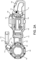
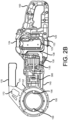
- the exemplary power tool 100 in the form of an exemplary thread forming tool 100, or pipe threader 100, is shown in FIGs. 2A and 2B , in which FIG. 2A is a side view and FIG. 2B is a cross-sectional view of the exemplary pipe threader 100.
- the exemplary pipe threader 100 includes a tool housing 110, including a battery housing 120, a motor housing 130, and a transmission housing 140 sequentially arranged along a longitudinal direction of the pipe threader 100.
- An operating head 150, or head portion 150 is positioned at a working end portion, or forward end portion of the pipe threader 100.
- One of a plurality of different cutting dies 155 see, for example, FIGs.
- a first handle 160, or rear handle 160 may be positioned at a first end portion of the housing 110, adjacent to the battery housing 120.
- a second handle 170, or front handle 170 is positioned at a second end portion of the housing 110, proximate the operating head 150 and/or the transmission housing 140.
- the front handle 170 may include, for example, retaining portion coupled to the operating head 150, including a retaining slot 172, and a grasping portion 175.
- the battery housing 120 defines an internal cavity 122 in which a power storage device, or battery125, may be removably received.
- a cover 124 may be coupled, for example, rotatably coupled, to the battery housing 120 to selectively open and close an opening into the cavity 122 for removal of the battery 125 from the cavity 122, and for replacement of the battery 125 into the cavity 122.
- the cover 124 may prevent unwanted material such as, for example, debris, moisture and the like, from entering the cavity 122 of the battery housing 120.
- the cover 124 may also contribute to the retention of the battery 125 in the cavity 122 of the battery housing 120, for example, during operation, transport, set up, and the like.
- an indicator panel 128 may be provided on the housing 110.
- the indicator panel 128 may provide external indicators to an operator, related to operation of the pipe threader 100.
- the indicator panel 128 may be selectively illuminated and/or selectively display one or more illumination patterns, to indicate an on/off state of the pipe threader 100, a capacity/charge level of the battery 125 received in the battery housing 120, and the like.
- a motor 135 is received in the motor housing 130.
- the motor 135 may be, for example, a brushless, bi-directional motor 135. That is, in some implementations, the motor 135 may be selectively operable in a forward direction, and in a reverse direction.
- an operational speed of the motor 135 may be varied, or changed, based on, for example, user selection.
- an operational speed of the motor 135 may be varied, or changed, based on, for example, an operation direction or mode of the motor 135.
- an operational direction, or operational mode, of the motor 135/pipe threader 100 may be selected by manipulation of a motor control switch 112, or forward/reverse switch 112, allowing for selection of one of a plurality of operational speeds of the motor 135 and/or selection of an operation direction of the motor 135.
- changes in the operational direction of the motor 135 may be achieved mechanically, by a reversing mechanism operably coupled with, for example, the motor 135 and/or the transmission 300 received in the transmission housing 140.
- the cutting die 155 may be removably received in the operating head 150, as shown in more detail in FIG. 3A .
- the operating head 150 may accommodate one of a plurality of different cutting dies 155, as shown in FIG. 3B .
- the plurality of cutting dies 155 may have different sizes, for cutting and/or forming threads on differently sized pipes, conduit, tubes, rods and the like.
- cutting dies 155 may be configured for forming external threads on an outer circumferential portion of a piece of stock.
- cutting dies 155 may be configured for forming internal threads on an inner circumferential portion of a piece of stock.
- one of the plurality of cutting dies 155 may be selected, based on, for example, a size (i.e., a diameter) of a piece of stock to be threaded.
- the selected cutting die 155 may include a plurality of engagement recesses 157 formed in a housing of the cutting die 155.
- the plurality of engagement recesses 157 formed in the housing of the cutting die 155 may receive a respective plurality of die head engagement pins 156 installed in an inner circumferential portion of the operating head 150.
- the plurality of die head engagement pins 156 may be spring biased, for example, in a radially inward direction.
- Engagement of the plurality of engagement pins 156 in the plurality of engagement recesses 157 may retain a position of the cutting die 155 relative to, for example, an output gear installed in the operating head 150, such that the cutting die 155 and the output gear rotate together in the engaged state.
- a piece of stock is inserted into the cutting die 155.
- Power may be applied to the motor 135 by, for example, manipulation of a power switch 114, or trigger 114.
- a force generated by operation of the motor 135 in a first direction (for example, the forward direction) is transmitted to the cutting die 155 via a transmission 300 received in the transmission housing 140. This force , in turn, rotates the cutting die 155 in the first direction, causing the cutting die 155 to engage with an end portion of the piece of stock.
- a direction of operation of the motor 135 may be reversed, for example, by manipulation of the forward/reverse switch 112.
- Operation of the motor 135 in the second direction may cause the cutting die 155 to rotate in the second direction, and the cutting die 155 to move in a second axial direction along the pipe, and through the previously cut threads, releasing the engagement of the pipe and the cutting die 155. This will be described in more detail below.
- the arrangement of the internal components of the pipe threader 100 may provide for ergonomic balance of the pipe threader 100.
- Ergonomic balance of the pipe threader 100 may improve user control during operation of the pipe threader 100, may improve precision of the modifications made to the workpiece/elongated stock during operation, and may enhance safety during operation of the pipe threader 100.
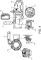
- FIG. 4 illustrates the relative placement of various internal components of the exemplary pipe threader 100, which may contribute to providing for ergonomic balance of the pipe threader 100.
- the battery 125 may be removably received in the internal cavity 122 formed in the battery housing 120.
- the cover 124 may selectively open and close the opening into the internal cavity 122. Enclosure of the battery 125 in the battery housing 120 may retain the battery 125 in a secured state, and/or in a connected state, in the battery housing 120. Enclosure of the battery 125 in the battery housing 120, and in particular, with the cover 124 closed against the internal cavity 122, may preclude the infiltration of external debris into the housing 110, and may preclude damage to the battery 125.
- the motor 135 is received in the motor housing 130.
- the motor 135 may be connected, for example, by wires, to receive power from the battery 125.
- a supply of power from the battery 125 to the motor 135 may be controlled by, for example, a power control board 138 selectively supplying power to the motor 135.
- the power control board 138 may control the supply of power to the motor 135 in response to, for example, manipulation of the motor control switch 112, or forward/reverse switch 112, a position of the power switch 114, or trigger 114, and the like.
- the power control board 138 may include a motion sensing device 138A.
- the motion sensing device 138A may detect a displacement and/or a velocity and/or an acceleration of the pipe threader 100 during operation.
- the motion sensing device 138A may include at least one of an accelerometer, a gyroscope and other such sensors.
- the power control board 138 may control operation of the motor 135 in a protection mode in response to detection of a displacement, and/or a velocity, and/or an acceleration, of the pipe threader 100 that is greater than a corresponding set threshold value.
- the power control board 138 may control the supply of power to the motor 135 to reduce, or suspend, operation of the motor 135, reverse an operation direction of the motor 135, and the like.
- the transmission 300 is received in the transmission housing 140.
- the transmission 300 may transfer power from the motor 135 to the cutting die 155 received in the operating head 150 of the pipe threader 100. That is, as described above, the transmission 300 transmits force from the motor 135 (operating in the first direction) to the cutting die 155, causing the cutting die 155 to rotate in the first direction. Similarly, the transmission 300 may transmit force from the motor 135 (operating in the second direction) to the cutting die 155, causing the cutting die 155 to rotate in the second direction.
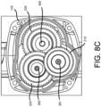
- the transmission 300 will be described in more detail with respect to FIGs. 8A and 8B .
- FIG. 8A is a side view
- FIG. 8B is a perspective view
- FIG. 8C is an end view, of the exemplary transmission 300 to be received in the transmission housing 140 of the exemplary pipe threader 100.
- a support plate 145 may be positioned between the motor housing 130 and the transmission housing 140, to, for example, support a coupling between the motor 145 and the transmission 300.
- the exemplary transmission 300 may be coupled to a motor pinion 137 mounted on an output shaft 136 of the motor 135.
- the exemplary transmission 300 may be, for example, a parallel axis transmission.
- a first reduction gear 310 mounted on a first shaft 391 of the exemplary transmission 300, may mesh with the motor pinion 137 to transfer power from the motor 135 to the transmission 300.
- the fourth reduction gear 340 may be an output gear 340, in the form of, for example, a bevel gear 340 that also changes the direction of rotation by 90 degrees.
- the bevel gear 340, or output gear 340 may transfer the force generated by the motor 135 to the operating head 150 of the pipe threader 100, to provide for the rotation of the cutting die 155.
- the bevel gear 340, or output gear 340 may be housed in a housing of the operating head 150, against a bearing ring. The force, or torque, generated by the motor 135 may be transmitted to the bevel gear 340, or output gear 340, through the parallel axis arrangement described above.
- This arrangement of the components of the transmission 300 may cause the bevel gear 340, or output gear 340, to rotate at a slower speed than the motor 135.
- This transfer of force to the operating head 150 may rotate the cutting die 155 received in the operating head 150.
- Rotation of the cutting die 155 may cause threads to be cut into an outer circumferential portion of a piece of elongated stock, such as, for example, a pipe, received in the cutting die 155 as described above.
- the exemplary transmission 300 shown in FIGs. 8A-3C is a parallel axis transmission, for purposes of discussion and illustration.
- other arrangement(s) of transmission components such as, for example, a planetary transmission design, may transfer force, i.e., rotational force, from the motor 135 to the operating head 150.
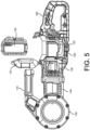
- the arrangement of components shown in FIGs. 3A through 8C may contribute to a positioning of a center of gravity CG of the pipe threader 100 at a location which provides for ergonomic balance of the pipe threader 100. That is, in the exemplary pipe threader 100 having the battery housing 120 (and the battery 125) positioned forward of the rear handle 160, the center of gravity CG of the exemplary pipe threader 100 may be substantially aligned with the front handle 170, as shown in FIG. 9 .
- This arrangement of components may provide for ergonomic balance of the pipe threader 100, which may improve user control of the device, may enhance operational safety, and may improve long term durability of the pipe threader 100.
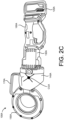
- a pipe threader 100A in accordance with implementations described herein, may have a tool housing 110A including a battery housing 120A, a motor housing 130A, a transmission housing 140A, and a operating head 150A, that are arranged as shown in FIG. 2C .
- the battery 125 may be received in the battery housing 120A
- the motor 135 may be received in the motor housing 130A
- the transmission may be received in the transmission housing 140A, substantially as described above with respect to the pipe threader 100 shown in FIGs. 2A and 2B .
- the arrangement of components of the exemplary pipe threader 100 shown in FIGs. 2A and 2B , with the battery housing 120 (and battery 125) positioned forward of the rear handle 160, and the center of gravity CG substantially aligned with the front handle 170, may provide improved rigidity of the housing 110, and of the pipe threader 100, particularly in a central portion of the pipe threader 100, compared to that of the exemplary pipe threader 100A shown in FIG. 2C .
- the improved rigidity provided by the arrangement shown in FIGs. 2A and 2B may further improve stability of the pipe threader 100 during use, and may further improve user control and operational safety.
- FIG. 10 is a perspective view of the exemplary thread forming system 1000, in accordance with the invention.
- the exemplary thread forming system 1000, shown in FIG. 10 includes the exemplary pipe threader 100 described above with respect to FIGs. 2A and 2B , for purposes of discussion and illustration.
- the exemplary thread forming system 1000, shown in FIG. 10 also includes the support device 200 that maintains, or secures, a position of a piece of elongated stock 10, or pipe 10, relative to the exemplary pipe threader 100.
- the support device 200 in accordance with implementations described herein, withstands relatively high torque during operation of the pipe threader 100.
- the support device 200 allows an axial biasing force to be applied to the cutting die 155 installed in the operating head 150 of the pipe threader 100.
- the axial biasing force applied to the cutting die 155 allows the cutting die 155 to engage an end portion of the elongated stock 10, to initiate threading of the elongated stock 10.
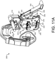
- FIG. 11A is a perspective view of the support device 200, in accordance with implementations described herein.
- FIG. 11B is a perspective view of the support device 200, with a biasing device 270 removed, so that other components of the support device 200 are more easily visible.
- the support device 200 includes a clamping device 230 that provides for coupling of the stock 10, or pipe 10, and the support device 200.
- the clamping device 230 may be selectively adjusted in response to manipulation of an adjustment device 240.
- the clamping device 230 is selectively engaged with the stock 10, or pipe 10, and disengaged from the stock 10, or pipe 10, in response to manipulation of a latching device 250.
- the support device 200 includes a reaction arm device 260 that is configured to abut, the pipe threader 100, to inhibit or restrict rotation of the pipe threader 100.
- the support device 200 also includes a biasing device 270 that may be rotatably coupled to the clamping device 230, and selectively engage the cutting die 155 installed in the operating head 150 of the pipe threader 100.
- An engagement of the biasing device 270 with the cutting die 155 allows an axial force to be safely applied to the cutting die 155, and may allow the cutting die 155 to, in turn, engage the end portion of the pipe 10 held by the clamping device 230 as the cutting die 155 rotates.
- the support device 200 includes a first support bracket 210, or upper support bracket 210, and a second support bracket 220, or lower support bracket 220 rotatably coupled to a first end portion of the upper support bracket 210.
- the clamping device 230 includes a first clamping face 232, or upper clamping face 232, on an upper jaw 233 of the upper support bracket 210, and a second clamping face 234, or lower clamping face 234, on a lower jaw 235 of the lower support bracket 220.
- the upper clamping face 232 and the lower clamping face 234 is configured to engage the piece of elongated stock 10 to be held, or supported, by the support device 200 during operation of the pipe threader 100.
- the upper clamping face 232 and/or the lower clamping face 234 may include pads, which may be removable/replaceable wear items on the support device 200.
- one of the upper clamping face 232 or the lower clamping face 234 may remain stationary, while the other of the upper clamping face 232 or the lower clamping face 234 may be moveable, so that the upper and lower clamping faces 232 and 234 may be moved into contact, or engagement, with a piece of stock 10, or pipe 10.
- the upper clamping face 232 may remain stationary, or fixed, on the upper support bracket 210, and a position of the lower clamping face 234 may be moved, or adjusted, in response to manipulation of the adjustment device 240.
- the adjustment device 240 may include a threaded adjusting knob 242 mounted on a threaded rod 244.
- the lower clamping face 234 may be coupled to an end portion of the threaded rod 244.
- the adjusting knob 242 may move axially along the threaded rod 244.
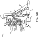
- the lower clamping face 234 may be moved upward, in a direction toward the upper clamping face 232, in response to rotation of the adjusting knob 242 in the first direction and corresponding upward movement of the threaded rod 242, while the lower support bracket 220/side plate 222 remains stationary, as shown in FIG. 12B .
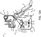
- the lower clamping face 234 may be moved downward, in a direction away from the upper clamping face 232, in response to rotation of the adjusting knob 242 in the second direction and corresponding downward movement of the threaded rod 244, while the lower support bracket 220/side plate 222 remains stationary, as shown in FIG. 12A .
- This type of manipulation of the adjustment device 240 may allow the clamping device 230 to be tightened against the pipe 10, to secure a position of the pipe 10 for threading.
- This type of manipulation of the adjustment device 240 may allow the clamping device 230 to be released from the pipe 10, to allow the pipe 10 to be removed after threading is complete.
- This type of manipulation of the adjustment device 240 may allow the clamping device 230 to accommodate different sizes and/or configurations of elongated stock 10 in the support device 200.
- FIG. 12B illustrates a first pipe 10A secured in the support device 200
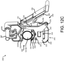
- FIG. 12C illustrates a second pipe 10B secured in the support device 200, a diameter of the second pipe 10B being greater than a diameter of the first pipe 10A.
- the adjustment device 240 has been manipulated to properly position the upper and lower clamping faces 232, 234 of the clamping device 230 to receive and secure the respective pipes 10A and 10B in the support device 200.
- the adjustment device 240 may include a scale indicator 246 that is visible to the operator, to facilitate adjustment of the position of the clamping faces 232, 234.
- the scale indicator 246 is provided on the lower jaw 235.
- the user may read the scale indicator 246 through a slot 224 formed in a side plate 222 of the lower support bracket 220. Reading of the scale indicator 246 in this manner may provide the user with indexing, facilitating the accommodation of a particular size of pipe 10 between the clamping faces 232, 234. This ability to rapidly adjust the spacing between the upper and lower jaws 233, 235 may facilitate the rapid accommodation of pieces of stock 10 within the clamping faces 232, 235 of the jaws 233, 235.
- the thread forming system comprises a latching device 250.
- the latching device 250 may be actuated, or engaged, to selectively inhibit, or restrict, relative rotation of the upper support bracket 210 and the lower support bracket 220, and maintain a secured position of the elongated stock 10 in the support device 200.
- actuation of the latching device 250 may maintain the respective positions of the components of the support device 200, and of the pipes 10 supported in the support device 200, as shown in FIGs. 12B and 12C .
- the latching device 250 may be disengaged, or released, to allow for the relative rotation of the upper support bracket 210 and the lower support bracket 220, and for the release of the stock 10, or pipes 10, from the support device 200.
- the latching mechanism 250 includes a latch handle 254 rotatably coupled to the first end portion of the upper support bracket 210 at a first pivot pin 251.
- a link 256 is rotatably coupled between the latch handle 254 and the lower support bracket 220.
- a first end portion of the link 256 is rotatably coupled to the latch handle 254 at a second pivot pin 252, and a second end portion of the link 256 is rotatably coupled to the lower support bracket 220 at a third pivot pin 253.
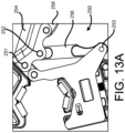
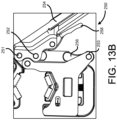
- FIG. 13A illustrates the latching device 250 in a disengaged, or unactuated position. From the position shown in FIG.
- a piece of stock 10 may be positioned in the clamping device 230, i.e., between the first and second clamping faces 232, 234, and the adjustment device 240 may be manipulated to secure the stock 10 in the clamping device 230, as shown in FIG. 12B .
- the latching device 250 may then be actuated to inhibit, or restrict, relative rotation of the upper and lower support brackets 210, 220, and maintain the secured, clamped position of the stock 10 in the clamping device 230.
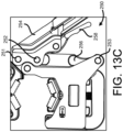
- the latch handle 254 is rotated from the position shown in FIG. 13A , through the interim position shown in FIG. 13B , and into the position shown in FIG. 13C .
- the link 256 is at a top dead center position, in which the first pivot pin 251, the second pivot pin 252 and the third pivot pin 253 are aligned in a straight line.
- the first end portion of the link 256 and the second pivot pin 252 are offset from the first pivot pin 251 and the third pivot pin 253.
- the link 256 may be adjustable in length, to provide for fine adjustment of the latching provided by the latching device 250.
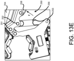
- Actuation of a release lever 258 may release, or disengage, the latching device 250, allowing for rotation of the upper and lower support brackets 210, 220, and removal of the piece of stock 10 from the support device 200. That is, as shown in FIG. 13D , application of an external force on the release lever 258, in the direction of the arrow F, pushing the release lever 258 toward the latch handle 254, may release, or disengage, the latching device 250, as shown in FIG. 13E . In the position shown in FIGs. 13C and 13D , the upper end portion of the release lever 258 is in contact with the link 256. In response to application of the force F, the upper end portion of the release lever 258 cams against the link 256, snapping the link 256 out of the locked, or latched, position, and releasing or disengaging the latching device 250.
- the ability to latch, and unlatch, the support device 200 in the manner described above, may allow for a relatively rapid removal of a completed work piece, and placement of a new work piece in the support device 200, particularly when processing work pieces of essentially the same size (i.e., diameter).
- Manipulation of the adjustment device 240 as described above may provide for fine adjustment of the positioning of the clamping faces 232, 234 in securing the work piece in the support device 200.
- the piece of elongated stock 10 (such as the exemplary pipe 10 referenced above for purposes of description and illustration) may be secured by the support device 10 as described with respect to FIGs. 11A through 13E .
- the exemplary pipe threader 100 may be positioned at the end portion of the pipe 10.
- the end of the pipe 10 may be positioned in the operating head 150 of the pipe threader 100, for example, in the cutting die 155 installed in the operating head 150, so that operation of the pipe threader 100 may cause threads to be formed in the end portion of the pipe 10.
- operation of the motor 135 in the first direction may cause corresponding rotation of the cutting die 155 in the first direction R1 about the axis of rotation A of the cutting die 155 and/or the central longitudinal axis A of the elongated piece of stock 10 received in the cutting die 155.
- this rotation of the cutting die 155 may cause rotation of, essentially the entire pipe threader 100 about the axis of rotation A.
- the reaction arm device 260 includes a reaction arm 262 coupled to the clamping device 230 of the support device 200.
- a first end portion of the reaction arm 262 may be coupled to the upper support bracket 210, and a second end portion of the reaction arm 262 may be configured to abut a portion of the pipe threader 100, so as to inhibit, or restrict, rotation of the pipe threader 100 about the axis of rotation A, during operation of the motor 135 and corresponding rotation of the cutting die 155 engaged with the pipe 10.
- the second end portion of the reaction arm 262 may be configured to engage a retaining portion of the pipe threader 100.
- the retaining portion of the pipe threader 100 is defined by a slot 172 formed in the front handle 170, in which the second end portion of the reaction arm 262 is received.
- the retaining portion may be defined by, for example, a lower surface 174 of the front handle 170, an outer surface 152 of the operating head/housing 110 of the pipe threader 100, and the like, which the second end portion of the reaction arm 262 may abut, or contact, so as to inhibit or restrict rotation of the pipe threader 100.
- the support device 200 may include a slot, similar to the slot 172 shown in FIG. 10 , in which such a reaction arm of the pipe threader 100 may be received. Engagement in this manner may stabilize a relative position of the pipe threader 100, the support device 200, and the piece of stock 10, during operation.
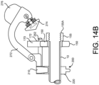
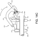
- FIG. 14A is a perspective view of the exemplary support device 200 including the exemplary biasing device 270, with a pipe secured in the support device 200.
- the cutting die 155 is positioned on the end portion of the pipe 10, but not installed in the operating head 150 of the pipe threader 100, simply so that components of the support device 200 are more easily visible.
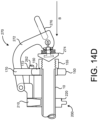
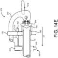
- FIGs. 14B-14E are cross sectional views of operation of the exemplary biasing device 270, in accordance with implementations described herein. In the example shown in FIGs.
- the biasing device 270 is rotatably coupled to the upper support bracket 210 of the clamping device 230, such that an axial biasing force may be applied to the cutting die 155 by a downward application of external force to the biasing device 270.
- Threading of a piece of elongated stock 10, such as, for example a pipe 10, by the exemplary pipe threader 100 may require that an axial force is applied to the cutting die 155, while the cutting die 155 is rotating, to initiate engagement between the cutting die 155 and the outer circumferential surface of the pipe 10, and initiate the cutting of threads into the pipe 10.
- an operator may place a hand directly on the outer facing side of the cutting die 155, while the cutting die 155 is rotating, to urge the rotating cutting die 155 onto the pipe 10 and initiate threading. This direct contact between the hand of the user and the rotating cutting die 155 may present safety hazards during operation, and/or may not yield the desired results.
- this direct contact with the rotating cutting die 155 may expose the hand of the user to burrs, metal debris, burning, blistering and the like. Additionally, depending on the size and/or type of stock 10 being modified, an operator may not be able to produce sufficient axial force in this manner, and/or may cause instability in the mounting of the stock 10 and/or fixture when applying an axial force in this manner. Accordingly, a biasing device 270 allows an operator to apply an axial biasing force to the rotating cutting die 155 safely, and with relatively less effort.
- the biasing device 270 is coupled, for example, rotatably coupled, to the clamping device of the support device 200.
- the biasing device 270 is rotatably coupled to the upper support arm 210, for purposes of discussion and illustration.
- the exemplary biasing device 270 includes a biasing arm 272, with a first end portion of the biasing arm 272 being rotatably coupled to the upper support bracket 210.
- a biasing plate 274 may be coupled to a second end portion of the biasing arm 272.
- the biasing device 270 may include a biasing handle 276 to facilitate the rotation of the biasing device 270, and the application of the axial biasing force.
- the operator may rotate the biasing arm 272, so as to selectively bring the biasing plate 274 into contact with the outward facing side 155A of the cutting die 155.
- the biasing device 270 is in a position that is rotated away from the cutting die 155 and the end portion of the pipe 10 to be threaded by the cutting die 155.
- the pipe 10 may be secured in the support device 200 by the clamping device 230, the adjusting device 240 and the latching device 250, with the reaction arm 262 engaged with the retaining portion of the pipe threader 100, as described above.
- Power may then be supplied to the motor 135, and a force generated by the motor 135 may be transmitted to the cutting die 155, to rotate the cutting die 155 about the axis of rotation A, as described above.
- the operator may rotate the biasing device 270 about the first end of the biasing arm 272, for example, in the direction C, as shown in FIG. 14C .
- Contact between the biasing plate 274 and the (rotating) cutting die 155 may be established by continued rotation of the biasing device 270 in the direction C.
- the operator may apply an axial biasing force B.
- Application of the axial biasing force in the direction B may cause the cutting die 155 to move axially, in the direction A1 along the pipe 10, as the cutting die 155 rotates, and the cutting surfaces of the cutting die 155 are brought into contact with the outer circumferential surface of the pipe 10, as shown in FIG. 14E .
- the cutting surfaces of the cutting die 155 engage the outer circumferential surface of the pipe 10, and the cutting die 155 continues to rotate (for example, in the first direction R1 as described above with respect to FIG. 10 ), the cutting surfaces may cut threads into the end portion of the pipe 10. With the cutting die 155 and the pipe 10 engaged in this manner, the external axial force may no longer be required for the cutting die 155 to continue to move axially in the axial direction A1 and cut threads into the pipe 10.
- an operation direction of the motor 135 may be changed, or reversed, causing the cutting die 155 to rotate in the second direction R2. Rotation of the cutting die 155 in the second direction R2 may cause the cutting die 155 to travel along the pipe 10 in the direction axial A2, back through the previously cut threads, so that the cutting die 155 and the pipe 10 may be disengaged.
- the operational speed of the motor 135 (and the corresponding rotational speed of the cutting die 155) in the second direction R2 may be greater than the operational speed of the motor 135 (and the corresponding rotational speed of the cutting die 155) in the first direction R1.
- the reduced resistance between the cutting die 155 and the previously cut threads during rotation of the cutting die 155 in the second direction R2 may allow for relatively rapid disengagement of the cutting die 155 and the pipe 10 once the threading operation is complete, thus enhancing operator convenience and utility.
- the rotational speed may be set based on a detected operational direction of the motor 135. In some implementations, the rotational speed may be set based on a detected operator manipulation of the motor control switch 112.
- the power control board 138 may include the motion sensing device 138A, including, for example, the gyroscope and/or the accelerometer that may selectively control operation of the motor 135 in a protection mode of operation. That is, in response to detection by the gyroscope and/or the accelerometer of the motion sensing device 138A of a displacement and/or a velocity and/or an acceleration of the pipe threader 100 that exceeds a corresponding preset threshold during operation, the power control board 138 may control the supply of power to the motor 135 to reduce, or suspend, operation of the motor 135. In some implementations, in implementing the protection mode, the power control board 138 may reverse the operation direction of the motor 135. The anti-kickback protection provided by operation in the protection mode may enhance safety both to the operator, and in the surrounding operational environment.
Landscapes
- Engineering & Computer Science (AREA)
- Mechanical Engineering (AREA)
- Sawing (AREA)
- Shearing Machines (AREA)
Claims (5)
- Gewindeformsystem (1000), umfassend:ein Elektrowerkzeug (100), das beinhaltet:ein Werkzeuggehäuse (110); undeinen Schneidkopf (150), der konfiguriert ist, um Gewinde in einem länglichen Halbzeugteil (10) zu formen, wobei der Schneidkopf (150) konfiguriert ist, um das Halbzeugteil (10) aufzunehmen und sich axial entlang einer Längsachse (A) des Halbzeugteils (10) zu bewegen, um die Gewinde zu formen; undeine Stützvorrichtung (200), die beinhaltet:eine Klemmvorrichtung (230), die konfiguriert ist, um eine Position des Halbzeugteils (10) in Bezug zum Elektrowerkzeug (100) für den Schneidkopf (150) zu sichern, um die Gewinde zu formen;eine Reaktionsarmvorrichtung (260), die einen Reaktionsarm (262) beinhaltet, der mit der Klemmvorrichtung (230) gekoppelt ist und konfiguriert ist, um an einem Rückhalteabschnitt des Elektrowerkzeugs (100) anzuliegen, um eine Drehung des Gehäuses (110) in Bezug zum Halbzeugteil zu verhindern, während der Schneidkopf (150) Gewinde formt; undeine Vorspannvorrichtung (270), die einen Vorspannarm (272) beinhaltet, der einen ersten Endabschnitt davon aufweist, der beweglich mit der Klemmvorrichtung (230) gekoppelt ist, wobei die Vorspannvorrichtung (270) konfiguriert ist, um den Schneidkopf (150) selektiv in Eingriff zu bringen, um den Schneidkopf (150) entlang der Längsachse (A) vorzuspannen;dadurch gekennzeichnet, dass die Klemmvorrichtung (230) weiter umfasst:eine obere Stützhalterung (210) mit einer ersten Klemmfläche (232), die konfiguriert ist, um in das Halbzeugteil (10) einzugreifen; undeine untere Stützhalterung (220), die beweglich mit der oberen Stützhalterung (210) gekoppelt ist, mit einer der ersten Klemmfläche (232) gegenüberliegenden zweiten Klemmfläche (234), und konfiguriert, um in das Halbzeugteil (10) einzugreifen;wobei die Klemmvorrichtung (230) weiter eine Verriegelungsvorrichtung (250) umfasst, die einen Riegel über der Mitte beinhaltet, der zwischen der unteren Stützhalterung (220) und der oberen Stützhalterung (210) gekoppelt ist;wobei der Riegel über der Mitte umfasst:einen Riegelgriff (254);einen ersten Drehstift (251), der den Riegelgriff (254) drehbar mit der oberen Stützhalterung (210) koppelt;eine Verbindung (256);einen zweiten Drehstift (252), der ein erstes Ende der Verbindung (256) drehbar mit dem Riegelgriff (254) koppelt; undeinen dritten Drehstift (253), der ein zweites Ende der Verbindung (256) drehbar mit der unteren Stützhalterung (220) koppelt.
- System nach Anspruch 1, wobei in einer ersten Position des Riegelgriffs (254) und der Verbindung (256) die obere Stützhalterung (210) in Bezug zur unteren Stützhalterung (220) drehbar ist.
- System nach Anspruch 2, wobei in einer zweiten Position des Riegelgriffs (254) und der Verbindung (256) eine Drehung der oberen Stützhalterung (210) in Bezug zur unteren Stützhalterung (220) eingeschränkt ist, sodass eine relative Position der oberen Stützhalterung (210) und der unteren Stützhalterung (220) gesichert ist.
- System nach Anspruch 3, wobei der Riegelgriff (254) und die Verbindung (256) als Reaktion auf eine Drehung des Riegelgriffs (254) um den ersten Drehstift (251) in einer ersten Richtung von der ersten Position in die zweite Position beweglich sind, in der der zweite Drehstift (252) und der erste Endabschnitt der Verbindung (256) über eine Ausrichtposition mit dem ersten Drehstift (251) und dem dritten Drehstift (253) hinaus beweglich sind.
- System nach Anspruch 3, das weiter einen vierten Stift umfasst, der einen Endabschnitt eines Lösegriffs (258) drehbar mit dem Riegelgriff (254) koppelt, wobei der Lösegriff (258) in der ersten Position entlang des Riegelgriffs (254) ausgerichtet ist und der Lösegriff (258) in der zweiten Position um den vierten Drehstift drehbar ist, sodass der Lösegriff (258) vom Riegelgriff (254) getrennt wird, und der zweite Drehstift (252) und der erste Endabschnitt der Verbindung (256) als Reaktion auf eine Drehung des Lösegriffs (258) zum Riegel (254) hin von der unteren Stützhalterung (220) weg drehbar sind, um eine Drehung der oberen Stützhalterung (210) und der unteren Stützhalterung (220) zu ermöglichen.
Priority Applications (1)
| Application Number | Priority Date | Filing Date | Title |
|---|---|---|---|
| EP25174513.9A EP4570403A3 (de) | 2018-12-12 | 2019-10-10 | Gewindeformungssystem |
Applications Claiming Priority (1)
| Application Number | Priority Date | Filing Date | Title |
|---|---|---|---|
| US16/218,011 US11344961B2 (en) | 2018-12-12 | 2018-12-12 | Pipe threading or cutting device |
Related Child Applications (2)
| Application Number | Title | Priority Date | Filing Date |
|---|---|---|---|
| EP25174513.9A Division EP4570403A3 (de) | 2018-12-12 | 2019-10-10 | Gewindeformungssystem |
| EP25174513.9A Division-Into EP4570403A3 (de) | 2018-12-12 | 2019-10-10 | Gewindeformungssystem |
Publications (2)
| Publication Number | Publication Date |
|---|---|
| EP3666437A1 EP3666437A1 (de) | 2020-06-17 |
| EP3666437B1 true EP3666437B1 (de) | 2025-06-11 |
Family
ID=68392687
Family Applications (2)
| Application Number | Title | Priority Date | Filing Date |
|---|---|---|---|
| EP19202388.5A Active EP3666437B1 (de) | 2018-12-12 | 2019-10-10 | System zum gewindeschneiden |
| EP25174513.9A Pending EP4570403A3 (de) | 2018-12-12 | 2019-10-10 | Gewindeformungssystem |
Family Applications After (1)
| Application Number | Title | Priority Date | Filing Date |
|---|---|---|---|
| EP25174513.9A Pending EP4570403A3 (de) | 2018-12-12 | 2019-10-10 | Gewindeformungssystem |
Country Status (2)
| Country | Link |
|---|---|
| US (2) | US11344961B2 (de) |
| EP (2) | EP3666437B1 (de) |
Families Citing this family (7)
| Publication number | Priority date | Publication date | Assignee | Title |
|---|---|---|---|---|
| WO2021263147A1 (en) * | 2020-06-26 | 2021-12-30 | Milwaukee Electric Tool Corporation | Die head for pipe threader |
| KR102805174B1 (ko) * | 2020-07-08 | 2025-05-09 | 현대자동차주식회사 | 차량의 화재 확산 방지 시스템 |
| WO2022081945A1 (en) | 2020-10-16 | 2022-04-21 | Milwaukee Electric Tool Corporation | Anti bind-up control for power tools |
| DE112021005790T5 (de) | 2020-11-05 | 2023-09-21 | Emerson Professional Tools, LLC. | Algorithmen und verfahren zur steuerung des gewindeschneidens von rohren |
| EP4341029A4 (de) * | 2021-05-17 | 2025-09-17 | Milwaukee Electric Tool Corp | Rohreinfädler |
| CN113500257B (zh) * | 2021-07-27 | 2022-07-12 | 杭州宏力管道机械有限公司 | 手持电动套丝机与套丝方法 |
| CN113894369B (zh) * | 2021-09-28 | 2024-06-04 | 杭州宏力管道机械有限公司 | 锂电手持式套丝机及套丝方法 |
Family Cites Families (86)
| Publication number | Priority date | Publication date | Assignee | Title |
|---|---|---|---|---|
| US2599696A (en) | 1952-06-10 | Drilling mechanism | ||
| US1705240A (en) | 1926-04-29 | 1929-03-12 | Devine Frank | Pipe-threading machine |
| US1852776A (en) | 1929-11-30 | 1932-04-05 | Walter L Hodeaux | Portable universal power tool |
| US1969854A (en) * | 1932-01-22 | 1934-08-14 | Borden Co | Pipe working tool |
| US2097358A (en) | 1936-05-02 | 1937-10-26 | Whittaker Henry Clay | Metal cutter |
| US2195568A (en) * | 1938-06-25 | 1940-04-02 | Andrew M Hexdall | Multipurpose tool |
| US2205148A (en) * | 1939-05-15 | 1940-06-18 | Frank E Mayotte | Electric die threader |
| US2678453A (en) | 1949-03-25 | 1954-05-18 | George E Rudolph | Supporting structure for portable power tools |
| DE946321C (de) | 1952-11-01 | 1956-07-26 | Albert Roller | Auf Baustellen und in der Werkstatt verwendbares, kraft- oder handangetriebenes Geraet zum Gewindeschneiden an rohr- oder stangenfoermigen Werkstuecken |
| US2770820A (en) | 1953-10-01 | 1956-11-20 | Carol Mary Wiegel | Portable pipe threading tool |
| US2879678A (en) | 1956-07-25 | 1959-03-31 | Design Engineers | Drill stand with adjustable and reversible electro-magnetic base |
| US3170214A (en) | 1961-09-18 | 1965-02-23 | Cochrane William Downie | Toggle clamps |
| US3316571A (en) | 1964-08-06 | 1967-05-02 | John N Cutrone | Portable power threader and vise |
| US3354784A (en) | 1965-11-02 | 1967-11-28 | United States Steel Corp | Portable milling machine |
| US3373637A (en) * | 1966-01-14 | 1968-03-19 | Collins Machinery Corp | Multiple purpose portable rotary drive unit |
| US3521313A (en) * | 1967-12-13 | 1970-07-21 | Slade H Baker | Powered thread cutter |
| JPS4710994U (de) | 1971-02-27 | 1972-10-09 | ||
| US4209274A (en) | 1978-07-12 | 1980-06-24 | Emerson Electric Co. | Portable power drive |
| US4231454A (en) | 1978-07-12 | 1980-11-04 | Raymond Engineering Inc. | Torque wrench with clutches in series |
| JPS5577436A (en) | 1978-12-01 | 1980-06-11 | Retsukisu Kogyo Kk | Cutting machine |
| US4501519A (en) | 1980-05-27 | 1985-02-26 | Leon Harry I | Threading die couple |
| GB2125719B (en) * | 1982-08-25 | 1985-11-27 | Foell Remswerk | Thread cutting tool |
| USD288167S (en) | 1983-06-20 | 1987-02-10 | Albert Roller GmbH & Co. KG Werkzeug- und Maschinenfabrik | Electric pipe threader and pipe clamp combination |
| DE8318378U1 (de) | 1983-06-24 | 1984-05-30 | Albert Roller GmbH & Co KG, Werkzeug- und Maschinenfabrik, 7050 Waiblingen | Elektrische gewindeschneidkluppe |
| US4655108A (en) | 1985-09-16 | 1987-04-07 | The E. H. Wachs Company | Tube-squaring tool and clamping mechanism |
| US4669929A (en) | 1986-01-10 | 1987-06-02 | Olesen Karl R | Joist drill |
| US4720000A (en) | 1986-07-15 | 1988-01-19 | Raymond Engineering Inc. | Torque wrench with clutches |
| US4808047A (en) | 1987-09-24 | 1989-02-28 | Acme-Cleveland Corporation | Variable speed motor tapping attachment |
| GB8725087D0 (en) | 1987-10-27 | 1987-12-02 | Rotabroach Ltd | Drilling machines |
| CN1016856B (zh) | 1988-03-28 | 1992-06-03 | 翟北春 | 撞击调距管工万能工具 |
| JPH0777691B2 (ja) | 1989-04-28 | 1995-08-23 | オ−クマ株式会社 | 数値制御方法及びその装置 |
| USD325504S (en) | 1989-09-19 | 1992-04-21 | Tobey Billey D | Tube cutter |
| US4953292A (en) | 1989-09-26 | 1990-09-04 | Tobey Billy D | Hand-holdable tube cutting device |
| JPH0435842A (ja) | 1990-05-31 | 1992-02-06 | Brother Ind Ltd | 加工ユニット制御装置 |
| JP2661422B2 (ja) | 1991-08-16 | 1997-10-08 | 三菱電機株式会社 | 加工装置および加工方法 |
| ES1018624Y (es) | 1991-10-02 | 1992-11-16 | Super-Ego Tools, S.A. | Maquina portatil electrica para roscar. |
| US5203650A (en) | 1992-01-09 | 1993-04-20 | Everett D. Hougen | Method and apparatus for drilling holes |
| US5528830A (en) | 1994-02-18 | 1996-06-25 | Hansen; Fredrick M. | Rotary cutting tool for tubing, conduit and the like |
| US5495672A (en) | 1994-08-29 | 1996-03-05 | The Pullman Co. | Tube cutter |
| USD365581S (en) | 1995-04-05 | 1995-12-26 | Everett D. Hougen | Rail drill |
| USD383960S (en) * | 1995-07-10 | 1997-09-23 | Tri Tool, Inc. | Tube end squaring tool |
| KR970020270A (ko) | 1995-10-31 | 1997-05-28 | 장관순 | 드링, 탭핑 머시인 주축의 구동 제어장치 |
| JP3375475B2 (ja) | 1995-11-09 | 2003-02-10 | 新日本製鐵株式会社 | 形鋼ウェブの穿孔装置 |
| US5829142A (en) | 1996-08-14 | 1998-11-03 | Rieser; Timothy John | Motorized tool having rotatably driven workpiece accessories |
| JPH11245118A (ja) | 1998-03-03 | 1999-09-14 | Brother Ind Ltd | ネジ加工制御装置 |
| US6202522B1 (en) | 1999-05-27 | 2001-03-20 | Tri Tool Inc. | Portable pipe end preparation machine tool |
| USD427499S (en) * | 1999-11-22 | 2000-07-04 | Donato L. Ricci | Tube squaring machine |
| US6551033B2 (en) | 2000-01-31 | 2003-04-22 | Yoshiaki Kakino | Tapping apparatus and method |
| DE10117121A1 (de) * | 2001-04-06 | 2002-10-17 | Bosch Gmbh Robert | Handwerkzeugmaschine |
| US6698048B1 (en) | 2002-01-25 | 2004-03-02 | R. T. Greene | Motorized device for cutting and cleaning a piece of pipe |
| ITPN20030020A1 (it) | 2003-03-12 | 2004-09-13 | Bordignon Simone | Maschiatore elettromeccanico a comando elettronico. |
| DE102004003202B4 (de) * | 2004-01-22 | 2022-05-25 | Robert Bosch Gmbh | Handgriff mit Erfassungseinrichtung |
| US7406769B1 (en) | 2004-08-02 | 2008-08-05 | Richard Toussaint | Pipe cutting apparatus |
| GB2422800A (en) | 2005-02-04 | 2006-08-09 | Stephen Gilbert | A thread cutting device |
| DE502006000137D1 (de) | 2005-04-28 | 2007-11-29 | Novartec Ag | Rohrschneider |
| JP2007046946A (ja) * | 2005-08-08 | 2007-02-22 | Toshiba Mach Co Ltd | 基板の両面形状測定装置及び基板の両面形状測定方法 |
| US8065938B1 (en) | 2006-04-10 | 2011-11-29 | Kravitch Nick C | Interchangable extension tool for performing operations in limited space work areas |
| DE112008000686B4 (de) | 2007-03-15 | 2016-07-28 | Milwaukee Electric Tool Corp. | Rohrschneider |
| USD568701S1 (en) | 2007-06-08 | 2008-05-13 | Nasiell Gustav M | Automatic tubing cutter |
| USD568702S1 (en) | 2007-06-08 | 2008-05-13 | Nasiell Gustav M | Tubing cutting device |
| US7845080B2 (en) | 2007-12-26 | 2010-12-07 | Nasiell Gustav M | Tubing cutting apparatus |
| WO2009117836A1 (en) | 2008-03-28 | 2009-10-01 | Quanser Consulting Inc. | Drill assembly and method to reduce drill bit plunge |
| US20100269649A1 (en) | 2009-04-28 | 2010-10-28 | Gordon Rantz | Power Threading and Cutting Device with Sliding Support |
| US9266178B2 (en) * | 2010-01-07 | 2016-02-23 | Black & Decker Inc. | Power tool having rotary input control |
| US9138818B2 (en) | 2010-08-16 | 2015-09-22 | Emerson Electric Co. | Systems and devices for performing powered threading operations |
| US9566652B2 (en) | 2011-04-29 | 2017-02-14 | Gustav M. Nasiell | Cordless clamping handle tubing cutter tool |
| US9505067B1 (en) | 2011-04-29 | 2016-11-29 | Gustav M. Nasiell | Pull-cord operated clamping handle tubing cutter tool |
| JP5325949B2 (ja) | 2011-08-08 | 2013-10-23 | ファナック株式会社 | タッピング加工装置 |
| US9095917B2 (en) | 2012-08-06 | 2015-08-04 | Emerson Electric Co. | Die head retaining mechanism |
| US20140166323A1 (en) | 2012-09-16 | 2014-06-19 | J. Carl Cooper | Kickback Reduction for Power Tools and Machines |
| CN203495649U (zh) | 2013-08-14 | 2014-03-26 | 杭州宏力管道机械有限公司 | 手提式电动套丝机的传动结构 |
| US9957744B2 (en) | 2013-09-13 | 2018-05-01 | Gary L. Hamman | Power tool to spring torsioner converter |
| US9434014B1 (en) | 2013-10-18 | 2016-09-06 | Bnsf Railway Company | Field-portable hole broaching machines and methods for using the same |
| US20150165534A1 (en) | 2013-12-13 | 2015-06-18 | Ridge Tool Company | Thread forming using an impact driver |
| DE102014208980A1 (de) | 2014-01-27 | 2015-07-30 | Robert Bosch Gmbh | Werkzeugmaschinenvorrichtung |
| DE102014209009A1 (de) | 2014-01-27 | 2015-07-30 | Robert Bosch Gmbh | Werkzeugmaschinenvorrichtung |
| DE102014209032A1 (de) | 2014-01-27 | 2015-07-30 | Robert Bosch Gmbh | Werkzeugmaschinenvorrichtung |
| US10189136B2 (en) | 2015-09-01 | 2019-01-29 | Jpw Industries Inc. | Power tool with digital variable reluctance motor control |
| US11047528B2 (en) | 2016-02-12 | 2021-06-29 | Black & Decker Inc. | Electronic braking for a power tool having a brushless motor |
| WO2018102487A1 (en) | 2016-11-30 | 2018-06-07 | Ridge Tool Company | Hybrid power tools |
| WO2019177776A1 (en) | 2018-03-16 | 2019-09-19 | Milwaukee Electric Tool Corporation | Pipe threader |
| WO2021263147A1 (en) * | 2020-06-26 | 2021-12-30 | Milwaukee Electric Tool Corporation | Die head for pipe threader |
| DE112021005790T5 (de) * | 2020-11-05 | 2023-09-21 | Emerson Professional Tools, LLC. | Algorithmen und verfahren zur steuerung des gewindeschneidens von rohren |
| US11684986B2 (en) * | 2020-12-18 | 2023-06-27 | Ridge Tool Company | Pipe threading mechanisms and systems |
| EP4341029A4 (de) * | 2021-05-17 | 2025-09-17 | Milwaukee Electric Tool Corp | Rohreinfädler |
| CN113894369B (zh) * | 2021-09-28 | 2024-06-04 | 杭州宏力管道机械有限公司 | 锂电手持式套丝机及套丝方法 |
-
2018
- 2018-12-12 US US16/218,011 patent/US11344961B2/en active Active
-
2019
- 2019-10-10 EP EP19202388.5A patent/EP3666437B1/de active Active
- 2019-10-10 EP EP25174513.9A patent/EP4570403A3/de active Pending
-
2022
- 2022-04-29 US US17/733,426 patent/US20220250180A1/en active Pending
Also Published As
| Publication number | Publication date |
|---|---|
| US11344961B2 (en) | 2022-05-31 |
| EP4570403A3 (de) | 2025-09-17 |
| US20200189017A1 (en) | 2020-06-18 |
| US20220250180A1 (en) | 2022-08-11 |
| EP3666437A1 (de) | 2020-06-17 |
| EP4570403A2 (de) | 2025-06-18 |
Similar Documents
| Publication | Publication Date | Title |
|---|---|---|
| EP3666437B1 (de) | System zum gewindeschneiden | |
| JP5852509B2 (ja) | 電動工具 | |
| US7997835B2 (en) | Multiple chuck hand tool | |
| US4434586A (en) | Machine tool, especially a hand-held power tool with a turnable clamping element for clamping a tool on the tool spindle | |
| US5025548A (en) | Right-angle drive for vertical milling machine | |
| JP2009531182A (ja) | 動力工具保護部 | |
| CA2610033A1 (en) | Power hand tool | |
| CN109789500B (zh) | 具有切割刀片安全特征的台锯 | |
| EP1998919B1 (de) | Revolverkopf-hand-bohrmaschine/antriebsvorrichtung | |
| US5079940A (en) | Roll grooving apparatus | |
| JP5909644B2 (ja) | 押付力調整装置及び動力工具 | |
| JPS6341692B2 (de) | ||
| US20090126960A1 (en) | Portable Power Tool with Drive Shaft Lock Means | |
| JP2007530295A (ja) | パイプ切断装置 | |
| JP2003236729A (ja) | マシニングセンター用の手動操作可能な工具ホルダー | |
| JP6322484B2 (ja) | 工作機械の工具折損検知装置 | |
| JP2008080446A (ja) | 電動式チャック開閉装置 | |
| WO2006043170A3 (en) | A machining head for machine tools with a shaft with low thermal expansion coefficient | |
| US10201864B2 (en) | Guide attachment for a rotary power tool | |
| JP2003181736A (ja) | 工作機械のワーク把持工具 | |
| JP5989453B2 (ja) | 電動回転工具 | |
| JP2004142005A (ja) | 回転工具 | |
| JP2011140082A (ja) | 棒材切断機 | |
| US2927486A (en) | Feed attachment for drills | |
| WO2007093959A1 (en) | Power tool |
Legal Events
| Date | Code | Title | Description |
|---|---|---|---|
| PUAI | Public reference made under article 153(3) epc to a published international application that has entered the european phase |
Free format text: ORIGINAL CODE: 0009012 |
|
| STAA | Information on the status of an ep patent application or granted ep patent |
Free format text: STATUS: THE APPLICATION HAS BEEN PUBLISHED |
|
| AK | Designated contracting states |
Kind code of ref document: A1 Designated state(s): AL AT BE BG CH CY CZ DE DK EE ES FI FR GB GR HR HU IE IS IT LI LT LU LV MC MK MT NL NO PL PT RO RS SE SI SK SM TR |
|
| AX | Request for extension of the european patent |
Extension state: BA ME |
|
| STAA | Information on the status of an ep patent application or granted ep patent |
Free format text: STATUS: REQUEST FOR EXAMINATION WAS MADE |
|
| RIN1 | Information on inventor provided before grant (corrected) |
Inventor name: CAI, YOUWEI Inventor name: RUDOLPH, SCOTT M. Inventor name: PEIFFER, JOHN MICHAEL Inventor name: YE, JINHUA Inventor name: PUZIO, DANIEL Inventor name: CEROLL, WARREN A. Inventor name: GROSS, PAUL G. Inventor name: BI, ZHENYANG |
|
| 17P | Request for examination filed |
Effective date: 20200624 |
|
| RBV | Designated contracting states (corrected) |
Designated state(s): AL AT BE BG CH CY CZ DE DK EE ES FI FR GB GR HR HU IE IS IT LI LT LU LV MC MK MT NL NO PL PT RO RS SE SI SK SM TR |
|
| STAA | Information on the status of an ep patent application or granted ep patent |
Free format text: STATUS: EXAMINATION IS IN PROGRESS |
|
| 17Q | First examination report despatched |
Effective date: 20230421 |
|
| GRAP | Despatch of communication of intention to grant a patent |
Free format text: ORIGINAL CODE: EPIDOSNIGR1 |
|
| STAA | Information on the status of an ep patent application or granted ep patent |
Free format text: STATUS: GRANT OF PATENT IS INTENDED |
|
| INTG | Intention to grant announced |
Effective date: 20250127 |
|
| P01 | Opt-out of the competence of the unified patent court (upc) registered |
Free format text: CASE NUMBER: APP_13484/2025 Effective date: 20250319 |
|
| GRAS | Grant fee paid |
Free format text: ORIGINAL CODE: EPIDOSNIGR3 |
|
| GRAA | (expected) grant |
Free format text: ORIGINAL CODE: 0009210 |
|
| STAA | Information on the status of an ep patent application or granted ep patent |
Free format text: STATUS: THE PATENT HAS BEEN GRANTED |
|
| AK | Designated contracting states |
Kind code of ref document: B1 Designated state(s): AL AT BE BG CH CY CZ DE DK EE ES FI FR GB GR HR HU IE IS IT LI LT LU LV MC MK MT NL NO PL PT RO RS SE SI SK SM TR |
|
| REG | Reference to a national code |
Ref country code: GB Ref legal event code: FG4D |
|
| REG | Reference to a national code |
Ref country code: CH Ref legal event code: EP |
|
| REG | Reference to a national code |
Ref country code: IE Ref legal event code: FG4D |
|
| REG | Reference to a national code |
Ref country code: DE Ref legal event code: R096 Ref document number: 602019070983 Country of ref document: DE |
|
| PG25 | Lapsed in a contracting state [announced via postgrant information from national office to epo] |
Ref country code: FI Free format text: LAPSE BECAUSE OF FAILURE TO SUBMIT A TRANSLATION OF THE DESCRIPTION OR TO PAY THE FEE WITHIN THE PRESCRIBED TIME-LIMIT Effective date: 20250611 Ref country code: ES Free format text: LAPSE BECAUSE OF FAILURE TO SUBMIT A TRANSLATION OF THE DESCRIPTION OR TO PAY THE FEE WITHIN THE PRESCRIBED TIME-LIMIT Effective date: 20250611 |
|
| REG | Reference to a national code |
Ref country code: LT Ref legal event code: MG9D |
|
| PG25 | Lapsed in a contracting state [announced via postgrant information from national office to epo] |
Ref country code: NO Free format text: LAPSE BECAUSE OF FAILURE TO SUBMIT A TRANSLATION OF THE DESCRIPTION OR TO PAY THE FEE WITHIN THE PRESCRIBED TIME-LIMIT Effective date: 20250911 Ref country code: GR Free format text: LAPSE BECAUSE OF FAILURE TO SUBMIT A TRANSLATION OF THE DESCRIPTION OR TO PAY THE FEE WITHIN THE PRESCRIBED TIME-LIMIT Effective date: 20250912 |
|
| REG | Reference to a national code |
Ref country code: NL Ref legal event code: MP Effective date: 20250611 |
|
| PG25 | Lapsed in a contracting state [announced via postgrant information from national office to epo] |
Ref country code: BG Free format text: LAPSE BECAUSE OF FAILURE TO SUBMIT A TRANSLATION OF THE DESCRIPTION OR TO PAY THE FEE WITHIN THE PRESCRIBED TIME-LIMIT Effective date: 20250611 |
|
| PG25 | Lapsed in a contracting state [announced via postgrant information from national office to epo] |
Ref country code: HR Free format text: LAPSE BECAUSE OF FAILURE TO SUBMIT A TRANSLATION OF THE DESCRIPTION OR TO PAY THE FEE WITHIN THE PRESCRIBED TIME-LIMIT Effective date: 20250611 |
|
| PG25 | Lapsed in a contracting state [announced via postgrant information from national office to epo] |
Ref country code: RS Free format text: LAPSE BECAUSE OF FAILURE TO SUBMIT A TRANSLATION OF THE DESCRIPTION OR TO PAY THE FEE WITHIN THE PRESCRIBED TIME-LIMIT Effective date: 20250911 |
|
| PG25 | Lapsed in a contracting state [announced via postgrant information from national office to epo] |
Ref country code: LV Free format text: LAPSE BECAUSE OF FAILURE TO SUBMIT A TRANSLATION OF THE DESCRIPTION OR TO PAY THE FEE WITHIN THE PRESCRIBED TIME-LIMIT Effective date: 20250611 |
|
| PG25 | Lapsed in a contracting state [announced via postgrant information from national office to epo] |
Ref country code: NL Free format text: LAPSE BECAUSE OF FAILURE TO SUBMIT A TRANSLATION OF THE DESCRIPTION OR TO PAY THE FEE WITHIN THE PRESCRIBED TIME-LIMIT Effective date: 20250611 |