EP3666434A1 - Bohrer, bohreinheit und bohrverfahren - Google Patents
Bohrer, bohreinheit und bohrverfahren Download PDFInfo
- Publication number
- EP3666434A1 EP3666434A1 EP19207608.1A EP19207608A EP3666434A1 EP 3666434 A1 EP3666434 A1 EP 3666434A1 EP 19207608 A EP19207608 A EP 19207608A EP 3666434 A1 EP3666434 A1 EP 3666434A1
- Authority
- EP
- European Patent Office
- Prior art keywords
- drill
- flow path
- supply port
- cutting oil
- drilling
- Prior art date
- Legal status (The legal status is an assumption and is not a legal conclusion. Google has not performed a legal analysis and makes no representation as to the accuracy of the status listed.)
- Pending
Links
- 238000005553 drilling Methods 0.000 title claims description 116
- 238000000034 method Methods 0.000 title description 9
- 239000010730 cutting oil Substances 0.000 claims abstract description 105
- 238000005520 cutting process Methods 0.000 claims abstract description 82
- 239000011148 porous material Substances 0.000 claims description 5
- 238000004519 manufacturing process Methods 0.000 claims description 4
- 230000002093 peripheral effect Effects 0.000 claims description 3
- 239000000463 material Substances 0.000 description 21
- 239000003921 oil Substances 0.000 description 10
- 238000007599 discharging Methods 0.000 description 5
- 229910052782 aluminium Inorganic materials 0.000 description 4
- XAGFODPZIPBFFR-UHFFFAOYSA-N aluminium Chemical compound [Al] XAGFODPZIPBFFR-UHFFFAOYSA-N 0.000 description 4
- 239000004918 carbon fiber reinforced polymer Substances 0.000 description 3
- 239000002131 composite material Substances 0.000 description 3
- 239000002648 laminated material Substances 0.000 description 3
- 229910052751 metal Inorganic materials 0.000 description 3
- RTAQQCXQSZGOHL-UHFFFAOYSA-N Titanium Chemical compound [Ti] RTAQQCXQSZGOHL-UHFFFAOYSA-N 0.000 description 2
- 241000276425 Xiphophorus maculatus Species 0.000 description 2
- 238000005461 lubrication Methods 0.000 description 2
- 239000002184 metal Substances 0.000 description 2
- 239000000047 product Substances 0.000 description 2
- 239000010936 titanium Substances 0.000 description 2
- 229910052719 titanium Inorganic materials 0.000 description 2
- 229910000997 High-speed steel Inorganic materials 0.000 description 1
- 230000005540 biological transmission Effects 0.000 description 1
- 230000015556 catabolic process Effects 0.000 description 1
- 239000000919 ceramic Substances 0.000 description 1
- 238000004140 cleaning Methods 0.000 description 1
- 238000001816 cooling Methods 0.000 description 1
- 230000003247 decreasing effect Effects 0.000 description 1
- 238000006731 degradation reaction Methods 0.000 description 1
- 230000006866 deterioration Effects 0.000 description 1
- 230000000694 effects Effects 0.000 description 1
- 239000000835 fiber Substances 0.000 description 1
- 238000003780 insertion Methods 0.000 description 1
- 230000037431 insertion Effects 0.000 description 1
- 239000010687 lubricating oil Substances 0.000 description 1
- 239000007769 metal material Substances 0.000 description 1
- 239000004745 nonwoven fabric Substances 0.000 description 1
- 239000012466 permeate Substances 0.000 description 1
- 239000008262 pumice Substances 0.000 description 1
- 239000011347 resin Substances 0.000 description 1
- 229920005989 resin Polymers 0.000 description 1
- 239000007787 solid Substances 0.000 description 1
- 239000004575 stone Substances 0.000 description 1
Images


Classifications
-
- B—PERFORMING OPERATIONS; TRANSPORTING
- B23—MACHINE TOOLS; METAL-WORKING NOT OTHERWISE PROVIDED FOR
- B23B—TURNING; BORING
- B23B49/00—Measuring or gauging equipment on boring machines for positioning or guiding the drill; Devices for indicating failure of drills during boring; Centering devices for holes to be bored
- B23B49/02—Boring templates or bushings
- B23B49/023—Bushings and their connection to the template
-
- B—PERFORMING OPERATIONS; TRANSPORTING
- B23—MACHINE TOOLS; METAL-WORKING NOT OTHERWISE PROVIDED FOR
- B23B—TURNING; BORING
- B23B51/00—Tools for drilling machines
-
- B—PERFORMING OPERATIONS; TRANSPORTING
- B23—MACHINE TOOLS; METAL-WORKING NOT OTHERWISE PROVIDED FOR
- B23B—TURNING; BORING
- B23B49/00—Measuring or gauging equipment on boring machines for positioning or guiding the drill; Devices for indicating failure of drills during boring; Centering devices for holes to be bored
- B23B49/003—Stops attached to drilling tools, tool holders or drilling machines
- B23B49/006—Attached to drilling machines
- B23B49/008—Attached to the nose of the drilling machines
-
- B—PERFORMING OPERATIONS; TRANSPORTING
- B23—MACHINE TOOLS; METAL-WORKING NOT OTHERWISE PROVIDED FOR
- B23B—TURNING; BORING
- B23B35/00—Methods for boring or drilling, or for working essentially requiring the use of boring or drilling machines; Use of auxiliary equipment in connection with such methods
-
- B—PERFORMING OPERATIONS; TRANSPORTING
- B23—MACHINE TOOLS; METAL-WORKING NOT OTHERWISE PROVIDED FOR
- B23B—TURNING; BORING
- B23B49/00—Measuring or gauging equipment on boring machines for positioning or guiding the drill; Devices for indicating failure of drills during boring; Centering devices for holes to be bored
- B23B49/02—Boring templates or bushings
-
- B—PERFORMING OPERATIONS; TRANSPORTING
- B23—MACHINE TOOLS; METAL-WORKING NOT OTHERWISE PROVIDED FOR
- B23B—TURNING; BORING
- B23B51/00—Tools for drilling machines
- B23B51/06—Drills with lubricating or cooling equipment
-
- B—PERFORMING OPERATIONS; TRANSPORTING
- B23—MACHINE TOOLS; METAL-WORKING NOT OTHERWISE PROVIDED FOR
- B23Q—DETAILS, COMPONENTS, OR ACCESSORIES FOR MACHINE TOOLS, e.g. ARRANGEMENTS FOR COPYING OR CONTROLLING; MACHINE TOOLS IN GENERAL CHARACTERISED BY THE CONSTRUCTION OF PARTICULAR DETAILS OR COMPONENTS; COMBINATIONS OR ASSOCIATIONS OF METAL-WORKING MACHINES, NOT DIRECTED TO A PARTICULAR RESULT
- B23Q11/00—Accessories fitted to machine tools for keeping tools or parts of the machine in good working condition or for cooling work; Safety devices specially combined with or arranged in, or specially adapted for use in connection with, machine tools
- B23Q11/10—Arrangements for cooling or lubricating tools or work
-
- B—PERFORMING OPERATIONS; TRANSPORTING
- B23—MACHINE TOOLS; METAL-WORKING NOT OTHERWISE PROVIDED FOR
- B23B—TURNING; BORING
- B23B2250/00—Compensating adverse effects during turning, boring or drilling
- B23B2250/12—Cooling and lubrication
-
- B—PERFORMING OPERATIONS; TRANSPORTING
- B23—MACHINE TOOLS; METAL-WORKING NOT OTHERWISE PROVIDED FOR
- B23B—TURNING; BORING
- B23B2251/00—Details of tools for drilling machines
- B23B2251/50—Drilling tools comprising cutting inserts
-
- B—PERFORMING OPERATIONS; TRANSPORTING
- B23—MACHINE TOOLS; METAL-WORKING NOT OTHERWISE PROVIDED FOR
- B23B—TURNING; BORING
- B23B51/00—Tools for drilling machines
- B23B51/0002—Drills with connected cutting heads, e.g. with non-exchangeable cutting heads; Drills with a single insert extending across the rotational axis and having at least two radially extending cutting edges in the working position
Definitions
- Embodiments described herein relate generally to a drill, a drilling unit, and a drilling method.
- a drilling method using a drilling jig such as a drilling plate and/or a guide bush
- a drilling method for deep hole processing with high precision using a guide bush which can supply cutting oil inside, has been proposed (for example, refer to Japanese Patent Application Publication JP 2015-120216 A ).
- An object of the present invention is to allow drilling with higher precision in the case of drilling by inserting a drill into a guide bush.
- a drill in general, includes: a body without a back taper and a cutting edge part.
- the body has a flow path of a cutting oil inside.
- the flow path is branched to a first flow path and a second flow path inside the body.
- the cutting edge part is integrated with the body.
- the cutting edge part has a first supply port that supplies the cutting oil toward a workpiece.
- the first supply port is an outlet of the first flow path.
- the body has a second supply port that supplies the cutting oil to a clearance formed between the body and a bush for positioning the body.
- the bush is used by inserting the body inside the bush.
- the second supply port is an outlet of the second flow path.
- the outlet of the second flow path is formed on an outer peripheral surface of the body.
- the second flow path has a pressure loss by which the cutting oil is not scattered from the second supply port in a radial direction of the body but exuded from the second supply port.
- a drilling unit includes the above-mentioned drill and the bush.
- a drilling method for producing a drilled product includes: using at least the above-mentioned drill and the bush for drilling the workpiece; and supplying the cutting oil.
- FIG. 1 shows a structure of a drilling unit including a drill according to the first embodiment of the present invention.
- FIG. 2 shows a state where the drilling unit shown in FIG. 1 is drilling a workpiece.
- a drilling unit 1 drills a workpiece W using a handheld drill driving device, having at least a rotor for rotating a desired cutting tool.
- the drilling unit 1 has a drill 2, a guide bush 3, and a drilling plate 4.
- the guide bush 3 is used for positioning the drill 2, by being inserted into a through hole, for positioning, formed in the drilling plate 4 or another drilling jig.
- the drilling plate 4 should have a structure to be easily placed depending on the structure of the workpiece W, it is often appropriate that the drilling plate 4 is produced by a user of the drilling unit 1. Therefore, the drilling unit 1 may be composed of the drill 2 and the guide bush 3, without the drilling plate 4 being an element of the drilling unit 1.
- the drilling plate 4 shown in the figures has a structure in which a through hole for inserting the guide bush 3 has been formed on a platy member. The guide bush 3 inserted into the through hole of the drilling plate 4 is fixed to the drilling plate 4 by a setscrew 4A.
- the workpiece W is a laminate material composed by overlapping three plate materials W1, W2, and W3.
- the workpiece W composed by overlapping the plate material W1 made of CFRP (carbon fiber reinforced plastics), the plate material W2 made of aluminum, and the plate material W3 made of titanium can be an object to be drilled by the drilling unit 1.
- a laminate material, a simple platy portion, a block-shaped portion or the like, each made of a same material, such as a metal or a composite material, can be an object to be drilled by the drilling unit 1.
- the drill 2 has a body 5, without a back taper, and a cutting edge part 6 forming the desired number of cutting edges.
- the drill 2 held by a handheld drill driving device or the like is also called a drill bit in order to distinguish from a drill driving device.
- One end of the body 5 is used as a shank 5A for holding the drill 2 with a holder of a drill driving device while the other end of the body 5 is integrated with the cutting edge part 6.
- At least the cutting edge part 6 side of the body 5 without a back taper has a constant diameter, and is inserted into the guide bush 3.
- the guide bush 3 has a cylindrical structure having a step through hole consisting of the first hole, having the first diameter, which guides the cutting edge part 6 in the workpiece W side, and the second hole, having the second diameter smaller than the first diameter, which guides the body 5 on the opposite side of the workpiece W.
- the outline of the guide bush 3 in the workpiece W side is determined so that the tolerance between the outline of the guide bush 3 in the workpiece W side and the diameter of the through hole for positioning formed in the drilling plate 4 or the like become a tolerance corresponding to clearance fit.
- the guide bush 3 can be positioned in the tool axis direction by making a ring-shaped stepped surface, perpendicular to the tool axis direction, contact with a surface of the drilling plate 4 or the like, as shown in the figures. Furthermore, the guide bush 3 can be fixed to the drilling plate 4 by holding the ring-shaped convex portion of the guide bush 3 between the setscrew 4A and the drilling plate 4, as shown in the figures.
- the cutting edges of the drill 2 may be attached to the cutting edge part 6 interchangeably.
- a drill whose cutting edge can be exchanged as an insert or a head is also called an insert drill.
- the body 5 and a portion of the cutting edge part 6 except the cutting edges also function as a holder for holding each cutting edge interchangeably.
- a two flute insert which has been on the market for conventional insert drills, can also be used as an insert for the drill 2. Therefore, the drill 2 may be composed of the body 5 and the cutting edge part 6 having a structure, in which each cutting edge can be attached while an existing general-purpose insert may be used as the cutting edges.
- the diameter of the end portion in the holder side of the body 5, which is not inserted in the guide bush 3, may be larger than not only the inside diameter of the guide bush 3 but the diameter of the cutting edge part 6 in order to secure rigidity.
- another connecting member such as the shank 5A or a screw, thicker than the diameter of the body 5 may be coupled to the holder side of the body 5.
- the drill 2 is a non-straight drill in which the diameter of the cutting edge part 6 is larger than the diameter of the body 5 in the cutting edge part 6 side. Also in that case, the diameter of a portion of the body 5 in the cutting edge part 6 side, which is used by being inserted in the guide bush 3, is constant.
- a flute or flutes for discharging chips in the cutting edge part 6 side of the body 5.
- helical flutes can be formed in the cutting edge part 6 side of the body 5 similarly to a twist drill.
- linear flutes may be formed in the cutting edge part 6 side of the body 5 similarly to a straight fluted drill.
- the length of a portion of the body 5, having a constant diameter without a back taper, is determined so that the drill 2 can be fed out in the tool axis direction. Therefore, the longer the length of the portion of the body 5 without a back taper is, the longer a distance that the drill 2 can be fed out in the tool axis direction can be. Accordingly, the diameters of the body 5, including a portion used as the shank 5A for holding with a holder, may be constant as shown in the figures.
- the diameter of the cutting edge part 6 may be same as the diameter of the body 5 to compose a straight drill, or the cutting edge part 6 and the body 5 may be made of a same material to compose a solid type drill. Also in that case, the cutting edge part 6 side of the body 5 does not have a back taper, and a tool diameter is constant.
- the price of the drill 2 can be reduced since only a cutting edge made of an expensive material, such as carbide or ceramics, can be exchanged when the cutting edge is worn while the body 5 is made of a cheap material, such as high-speed steel, similarly to the conventional insert drill. Since there are few straight drills without a back taper in recent years, to manufacture a straight drill newly requires large scale equipment.
- At least one flow path 7 of a cutting oil is formed inside the body 5.
- the cutting oil is supplied to the flow path 7 in the body 5 from the holder side of the body 5. Therefore, it is practical to form an entrance of cutting oil on an end face in the holder side of the body 5.
- the linear flow path 7 of cutting oil has been formed on the tool axis of the body 5 whose diameter is constant.
- the body 5 has a cylindrical structure.
- the flow path 7 of the cutting oil may be formed at a position which is not on the tool axis of the body 5.
- a plurality of the flow paths 7, parallel to the tool axis, may be formed in the body 5.
- the cutting oil supplied to the flow path 7 in the body 5 is mainly supplied from the cutting edge part 6 to the workpiece W through the flow path 7 in the body 5. Therefore, at least one outlet of the cutting oil is formed in the cutting edge part 6.
- Each outlet of the cutting oil is used as the first supply port 8A for supplying the cutting oil toward the workpiece W from the tip of the drill 2.
- the four first supply ports 8A have been formed in the cutting edge part 6 of the drill 2.
- the body 5 has the second supply port 8B or the second supply ports 8B for supplying the cutting oil to the gap formed between the guide bush 3 and the body 5.
- the flow path 7 of the cutting oil can be branched to the first flow paths 7A and the second flow paths 7B inside the drill 2.
- the cutting oil can be supplied to the first supply ports 8A through the first flow paths 7 while the cutting oil can be supplied to the second supply ports 8B through the second flow paths 7B.
- the structure of the body 5 can be simplified with one entrance of the cutting oil into the body 5.
- each second supply port 8B on the outer periphery of the body 5 it is appropriate to open each second supply port 8B on the outer periphery of the body 5 in order to supply sufficient amount of the cutting oil to the clearance gap formed between the guide bush 3 and the body 5.
- the second supply port 8B can be opened on the outer periphery of the body 5 by forming the flow path 7 parallel to the tool axis and branching the second flow path 7B in the direction perpendicular to the tool axis.
- the central axis of the second flow path 7B is made perpendicular to the tool axis, processing for forming the second flow path 7B in the body 5 becomes easy.
- the second flow path 7B oblique toward the workpiece W side may be formed in the body 5 so that the cutting oil promptly permeates the workpiece W side through the clearance formed between the guide bush 3 and the body 5. Therefore, the second flow path 7B can also be formed in the body 5 so that an angle formed between the central axis of the second flow path 7B and the tool axis becomes not less than 10 degrees and not more than 90 degrees.
- the second supply port 8B may be opened in a flute or in a margin portion formed between the flutes.
- the cutting oil supplied toward the workpiece W from the first supply ports 8A formed in the cutting edge part 6 is used for the purpose of discharging chips, reducing cutting resistance, cooling or the like.
- the single second supply port 8B may be formed as shown in the figures, for example. Thereby, the structure of the body 5 can be simplified with allocating appropriate amounts of the cutting oil. Note that, a plurality of the second supply ports 8B may be formed on the body 5 in order to obtain a sufficient amount of supply of the cutting oil to the space between the guide bush 3 and the body 5 regardless of drilling conditions.
- the drill 2 When the workpiece W is drilled by the drill 2, the drill 2 is fed out in the tool axis direction with making the body 5 slidably fit to the guide bush 3 as shown in FIG. 2 . Therefore, a relative position of the second supply port 8B to the guide bush 3 changes. It is desirable to supply the cutting oil to the space formed between the guide bush 3 and the body 5 at the latest by the time drilling starts, i.e., until the cutting edges of the drill 2 contact the workpiece W.
- the second supply port 8B can be formed at the position where the second supply port 8B opens inside the guide bush 3 in the state that the cutting edge part 6 is not protruding from inside the guide bush 3 as exemplified in FIG. 1 . Thereby, the cutting oil can be certainly supplied between the guide bush 3 and the body 5 before drilling starts.
- the second supply port 8B is exposed outside the portion of the guide bush 3, which slidably fits the body 5, as exemplified in FIG. 2 . Nevertheless, the lubricity between the guide bush 3 and the body 5 can be maintained since oil film of the cutting oil remains between the guide bush 3 and the body 5 once the cutting oil is supplied between the guide bush 3 and the body 5.
- a position of the second supply port 8B may be determined in consideration of a distance between the guide bush 3 and the workpiece W.
- a drilled product can be manufactured by drilling the workpiece W with supplying the cutting oil using at least the drill 2 and the guide bush 3 which have the above-mentioned structures.
- the drilling unit 1 and the drilling method use the drill 2, used by being inserted in the guide bush 3, without a back taper and having at least one oil hole for supplying a cutting oil between the guide bush 3 and the drill 2.
- the accuracy in drilling can be improved.
- the reason is as follows.
- FIG. 3 shows an example case of drilling using the conventional straight drill 10 having a back taper and the guide bush 11.
- the typical drill 10 has a back taper.
- the back taper is formed so that the drill 10 does not contact with inner walls of a hole even when the drill 10 expands with heat during drilling.
- the back taper is standardized, and the taper which becomes thin toward the direction of a shank is formed in the drill 10 so that the diameter of the drill 10 is thinned by 0.04 mm to 0.1 mm per 100 mm in length.
- candidates of a material of the workpiece W include a metal, such as aluminum or titanium, a composite material, such as CFRP, which consists of a resin reinforced with a fiber and a laminate material which consists of overlapped metal and composite material.
- a metal such as aluminum or titanium
- CFRP composite material
- CFRP which consists of a resin reinforced with a fiber and a laminate material which consists of overlapped metal and composite material.
- FIG. 4 is an enlarged vertical longitudinal sectional view showing a structure of a body composing a drill according to the second embodiment of the present invention.
- FIG. 5 is a right side view of the body shown in FIG. 4 .
- the drilling unit 1A in the second embodiment shown in FIG. 4 is different from the drilling unit 1 in the first embodiment in the point that the second flow path 7B formed in the body 5 composing the drill 2 is made exchangeable.
- Other structures and functions of the drilling unit 1A in the second embodiment does not substantially differ from those of the drilling unit 1 in the first embodiment. Therefore, only the body 5 composing the drill 2 is illustrated. Then, same signs are attached to the same elements and corresponding elements and explanation thereof is omitted.
- a through hole having a diameter larger than that of the second flow path 7B can be formed at the position of the body 5 at which the second flow path 7B should be formed, and a female screw can be formed inside the through hole.
- a cylindrical member 20 of which outer surface forms a male screw and which has the second flow path 7B along the center can be fastened to the female screw formed in the through hole of the body 5. That is, the cylindrical member 20 in which the second flow path 7B is formed can be inserted into the through hole which has been formed in the body 5.
- the member 20 can be detached and attached from and to the body 5 of the drill 2.
- a groove for a flat-bladed screwdriver is formed in the end surface in the outside of the member 20 so that the member 20 can be easily detached from and attached to the body 5 of the drill 2.
- preparing the members 20 in which the second flow paths 7B and the second supply ports 8B having diameters D different from each other have been formed allows changing the size of the second flow path 7B and the second supply port 8B by exchanging one of the members 20 with another one.
- any one of the members 20 forming the second supply ports 8B and the second flow paths 7B in different sizes respectively is to be attached to the body 5 of the drill 2 so that the member 20 can be exchanged.
- the member 20 of which the diameter D of the second flow path 7B and the second supply port 8B is 0.5 mm and the member 20 of which the diameter D of the second flow path 7B and the second supply port 8B is 1 mm may be prepared, and one of them can be chosen in accordance with the drilling conditions.
- the member 20 in which the second flow path 7B and the second supply port 8B having another diameter D have been formed may be prepared.
- the cutting oil supplied to the flow path 7 of the body 5 from a drill driving device can be distributed to the first flow paths 7A and the second flow path 7B with appropriate amounts. Specifically, supplying an excess quantity of the cutting oil to the gap between the guide bush 3 and the body 5 from the second supply port 8B can be prevented while supplying an insufficient quantity of the cutting oil to the gap between the guide bush 3 and the body 5 from the second supply port 8B can be prevented.
- the important drilling conditions which should be taken into consideration in determining the diameter D of the second flow path 7B and the second supply port 8B as an appropriate size include a cutting resistance and an oil pressure of the cutting oil supplied to the drill 2 from a drill driving device. Specifically, when the oil pressure of the cutting oil supplied to the body 5 of the drill 2 from a drill driving device is high enough, sufficient quantity of the cutting oil can be injected towards the workpiece W from the first supply ports 8A even when the cutting resistance is large.
- the cutting resistance changes in accordance with a depth of hole to be drilled, a material of the workpiece W, and a material of the cutting edges.
- the diameter D of the second flow path 7B and the second supply port 8B can be changed in accordance with a pressure of the cutting oil supplied from a drill driving device to the drill 2, a depth of hole to be drilled, a material of the workpiece W, and a material of the cutting edges.
- the diameter D of the second flow path 7B and the second supply port 8B can be made large so that a sufficient quantity of the cutting oil can be led from the second flow path 7B and the second supply port 8B to the gap between the guide bush 3 and the body 5.
- the diameter D of the second flow path 7B and the second supply port 8B can be made small so that most part of the cutting oil is prevented from being supplied from the second flow path 7B and the second supply port 8B to the gap between the guide bush 3 and the body 5 while the amount of the cutting oil supplied from the first supply ports 8A to the workpiece W can be secured.
- Some drilling examinations can experientially determine a size of the second flow path 7B and the second supply port 8B appropriate for every conditions, such as a pressure of the cutting oil supplied from a drill driving device to the drill 2, a depth of hole to be drilled, a material of the workpiece W and a material of the cutting edges.
- the size of the second flow path 7B and the second supply port 8B for supplying the cutting oil to the space between the guide bush 3 and the body 5 can be adjusted.
- the cutting oil supplied from a drill driving device to the drill 2 can be distributed to a part to be drilled of the workpiece W, and the space between the guide bush 3 and the body 5 with adequate amounts.
- the second flow path 7B and the second supply port 8B may be formed on a flute or a margin of the body 5, similarly to the first embodiment. Therefore, the through hole and the female screw for inserting the member 20 can also be formed on a flute or margin of the body 5. Then, the member 20 can be attached to the flute or margin of the body 5.
- FIG. 6 shows a structure of a drilling unit including a drill according to the third embodiment of the present invention.
- FIG. 7 shows a state where the drilling unit shown in FIG. 6 is drilling a workpiece.
- the drilling unit 1B in the third embodiment shown in FIG. 6 is different from the drilling unit 1A in the second embodiment in the point that members 20 each forming the second flow path 7B and the second supply port 8B can be attached at positions different in the tool axis direction of the drill 2.
- Other structures and functions of the drilling unit 1B in the third embodiment does not substantially differ from those of the drilling unit 1A in the second embodiment. Therefore, same signs are attached to the same elements and corresponding elements and explanation thereof is omitted.
- the through holes and the female screws for inserting the members 20, each forming the second flow path 7B and the second supply port 8B, may be formed at plural positions of the body 5 different in the tool axis direction. Then, the second flow paths 7B and the second supply ports 8B can be formed at different positions in the tool axis direction of the drill 2.
- the members 20 are respectively attached to two different positions of the body 5 in the tool axis direction so that the members 20 can be attached and detached to and from the body 5.
- the cutting oil can be continuously supplied to the space between the guide bush 3 and the body 5 from another second supply port 8B formed at a different position in the tool axis direction. Consequently, the length of the body 5 which can be fed out in the tool axis direction toward the workpiece W with sliding fit to the guide bush 3 by supply of the cutting oil can be increased. As a result, a deep hole can be drilled using the guide bush 3 as shown in FIG. 7 .
- the distance between the adjacent second supply ports 8B can be determined according to a length of the guide bush 3 to which lubricity to the body 5 should be given.
- the cutting oil discharged out from each second supply port 8B remains as an oil film, during a certain length of period, on the surface of the body 5 and inside of the guide bush 3. Accordingly, it is appropriate to determine the distance between the adjacent second supply ports 8B so that an oil film may not break off between the guide bush 3 and the body 5 even when the body 5 is slid relative to the guide bush 3 by sending out the drill 2 in the tool axis direction.
- the second supply ports 8B can be arranged at an interval at which an oil film would not break off between the guide bush 3 and the body 5.
- the distance between the second supply ports 8B can be determined so that the cutting oil discharged out from the second supply port 8B adjacent the shank 5A side of the body 5 may arrive at the space, to which the cutting oil should be supplied, between the guide bush 3 and the body 5 through the body 5 before the second supply port 8B in the cutting edge part 6 side is exposed from the space between the guide bush 3 and the body 5.
- the distance between the second supply ports 8B can be determined so that the second supply port 8B adjacent the shank 5A side of the body 5 may arrive at the space, to which the cutting oil should be supplied, between the guide bush 3 and the body 5 before the second supply port 8B in the cutting edge part 6 side is exposed from the space between the guide bush 3 and the body 5, for example.
- the distance between the second supply ports 8B can be determined to not more than the length in the tool axis direction of the space, to which the cutting oil should be supplied, between the guide bush 3 and the body 5, i.e., the length of the guide bush 3 which slidingly fits to the body 5.
- the single second supply port 8B in the same position in the tool axis direction, as explained in the first embodiment. Accordingly, forming the single second supply port 8B in the same position in the tool axis direction leads to simplification of the structure of the drill 2 and reduction of a manufacturing cost of the drill 2. Nevertheless, the number of the second supply ports 8B formed in the same position in the tool axis direction may be more than one in order to obtain a sufficient amount of supply of a cutting oil to the space between the guide bush 3 and the body 5 regardless of drilling conditions.
- the second supply port B in the shank 5A side of the body 5 may become unnecessary for drilling a shallow hole. Accordingly, a plug member for blockading the second flow path 7B and the second supply port 8B may be inserted to the through hole and the female screw which have been formed in the body 5, instead of the member 20 for forming the second flow path 7B and the second supply port 8B.
- FIG. 8 is a longitudinal sectional view of the body 5 showing an example case where the through hole for inserting the member 20 shown in FIG. 6 is blockaded with the plug member 21.
- the plug member 21 when the columnar plug member 21 of which a male screw has been formed on the outer circumference is produced, the plug member 21 can be attached and detached to and from the body 5. Thereby, the second flow path 7B and the second supply port 8B can be blockaded by fastening the male screw of the plug member 21 to the female screw formed in the through hole for insertion of the member 20, as necessary, such as a case of drilling a shallow hole. As a result, supply of useless cutting oil can be reduced.
- the plug member 21 which blockades the second flow path 7B and the second supply port 8B can be also used to the drill 2 in the second embodiment.
- the drill 2 can be used even in the case of drilling without using the guide bush 3. Namely, flexibility can be given to the drill 2.
- the drilling unit 1B is composed by an insert drill of which cutting edges can be exchanged.
- FIG. 9 is a longitudinal sectional view showing an example case where the drilling unit 1B is composed by an insert drill 2A of which body 5 has helical flutes and cutting edges can be exchanged.
- FIG. 10 is a longitudinal sectional view showing a state where the drilling unit 1B shown in FIG. 9 is drilling a workpiece W.
- FIG. 11 is an enlarged vertical longitudinal sectional view near the tip of the insert drill 2A shown in FIG. 9 .
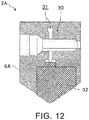
- FIG. 12 is a longitudinal sectional view showing an example of structure in the cutting edge part 6A of the insert drill 2A shown in FIG. 9 .
- the drilling unit 1B can be composed of the insert drill 2A.
- the structure of the cutting edge part 6A of the insert drill 2A can be made to the structure in which the width of the slit 31 can be changed by fastening the bolt 30 as shown in FIG. 12 , for example. Specifically, when the bolt 30 is fastened to make the width of the slit 31 narrow, the cutting edge 32 can be inserted and held by the cutting edge part 6A. On the contrary, when the bolt 30 is loosened to make the width of the slit 31 expanded, the cutting edge 32 can be removed from the cutting edge part 6A.
- the drilling unit 1B can be configured by the insert drill 2A of which the cutting edge part 6A and the body 5 function as a holder of the cutting edge 32.
- the body 5 of the insert drill 2A on which helical flutes have been formed has the six second flow paths 7B and the six second supply ports 8B.
- the two second flow paths 7B and the two second supply ports 8B are formed at each of three positions different in the tool axis direction. Accordingly, a deep hole can be processed using the insert drill 2A.
- the second flow path 7B and the second supply port 8B can be formed in any of a flute portion and a margin portion, as exemplified in FIG. 9 and FIG. 10 .
- the insert drill 2A can be used with being attached to a handheld drill driving device 40.
- the male screw 2B is formed in the back end side of the insert drill 2A so that the male screw 2B of the insert drill 2A is fasten to the female screw 41 which has been formed in the handheld drill driving device 40, thereby the insert drill 2A is held by the drill driving device 40.
- the drill driving device 40 has the cylindrical nosepiece 42 which shields the insert drill 2A, and the nosepiece 42 is connected with the guide bush 3. Specifically, the male screw which has been formed on the external surface of the guide bush 3 is fasten to the female screw which has been formed inside of the tip side of the nosepiece 42, thereby the nosepiece 42 is connected with the guide bush 3.
- the handheld drill driving device 40 having the nosepiece 42 which has a structure connectable to the guide bush 3 may be an element of the drilling unit 1B. This is the same in the first embodiment and the second embodiment.
- the second flow paths 7B and the second supply ports 8B can be formed at different positions in the tool axis direction of the drill 2 so that a deep hole can be processed. Moreover, the second flow path 7B and the second supply port 8B can also be blockaded by the plug member 21 so that a shallow hole can also be processed.
- FIG. 13 is a perspective view showing the first structural example of a member inserted into at least one through hole formed in a body of a drill according to the fourth embodiment of the present invention.
- FIG. 14 is a perspective view showing the second structural example of a member inserted into at least one through hole formed in a body of a drill according to the fourth embodiment of the present invention.
- the drilling unit 1C in the fourth embodiment shown in FIG. 13 or FIG. 14 is different from each of the drilling unit 1, the drilling unit 1A and the drilling unit 1B in the other embodiments in the point that the respective pressure losses of the second flow paths 7B formed in the body 5 of the drill 2 are determined so that the cutting oil may be exuded from the second supply ports 8B formed on the outer peripheral surface of the body 5 as the outlets of the second flow paths 7B respectively without being scattered from the second supply ports 8B in the radial direction of the body 5.
- drilling unit 1C in the fourth embodiment do not substantially differ from those of the drilling unit 1, the drilling unit 1A and the drilling unit 1B in the other embodiments. Therefore, only a member 20A, a member 20B and a member 20C each forming the second flow path 7B are illustrated. Then, the same signs are attached to the same elements and the corresponding elements, and explanation thereof is omitted.
- each second flow path 7B becomes larger as the area of the cross section is smaller since the frictional resistance with the cutting oil increases.
- the cross section area of at least a part of each second flow path 7B can be determined so that the pressure loss of the second flow path 7B becomes one with which the cutting oil is exuded without being scattered from the second supply port 8B in the radial direction of the body 5.
- each second flow path 7B can be increased by inserting the column-shaped member 20A, made of a porous material as exemplified in FIG. 13 , in a hole reaching the first flow path 7A from the outer surface of the body 5.
- forming at least a part of each second flow path 7B with a porous material makes it possible to make the pressure loss of each second flow path 7B be a pressure loss by which the cutting oil is not scattered from the second supply port 8B in the radial direction of the body 5 but exuded from the second supply port 8B.
- porous material examples include porous aluminum in addition to felt (a non-woven fabric), pumice stone and the like.
- porous aluminum when porous aluminum of which workability and wear resistance are preferable is used, it becomes easy to produce the member 20 A, which forms the second flow path 7B, and attach the member 20 A to the body 5.
- the member 20 B forming the second flow path 7B whose cross section area has been adjusted as exemplified in FIG. 14 may also be inserted in each through hole formed in the body 5, similarly to the second embodiment.
- FIG. 14 shows an example case where a slit having a rectangular cross section has been formed, as the second flow path 7B, in the member 20 B, the second flow path 7B having a circular cross section may be formed in the member 20 B.
- the second flow path 7B having an adjusted cross section area may be formed directly in the body 5, similarly to the first embodiment.
- the member 20 B forming the second flow path 7B can be exchanged. Therefore, the plurality of the members 20 B respectively forming the second flow paths 7B having pressure losses different from each other may be prepared so that one of the members 20 B can be interchangeably attached to the body 5.
- a direction of the slit may also be changed. Accordingly, a direction of a slit and/or the size of the second flow path 7B may be changed according to cutting conditions, such as a supply pressure and a kind of the cutting oil, the size and rotation speed of the drill 2, a material of the workpiece W and a depth of a hole to be drilled.
- each second flow path 7B is a small clearance of which inside diameter or width is about not more than 0.5 mm.
- the columnar member 20 which is not hollow and has a male screw on the outer surface, like the plug member 21 shown in FIG. 8 , may be fastened to a female screw formed in each through hole of the body 5 so that a clearance formed between the male screw formed on the columnar member 20 and the female screw formed in each through hole of the body 5 can be used as the second flow path 7B.
- FIG. 15 is an enlarged partial sectional view of the body 5 and the columnar member 20C, showing an example in which a clearance formed between a male screw and a female screw is used as the second flow path 7B.
- a male screw 50A can be formed on the outer surface of the columnar member 20C while a female screw 50B can be formed in each through hole of the body 5.
- a clearance called a crest clearance of the male screw 50A
- a clearance called a root clearance of the male screw 50A
- each of the clearances formed between the male screw 50A and the female screw 50B can be used as the second flow path 7B for discharging and exuding the cutting oil from the body 5.
- the second flow path 7B becomes spiral and the width of the second flow path 7B can be adjusted by selecting tolerance classes of a male screw and a female screw which classify fitting between the male screw and the female screw into classifications including precise, middle and rough.
- At least one of central axes of the second flow paths 7B may be slanted in the workpiece W side so that the cutting oil may be discharged not in the rotating radial direction of the body 5 but toward the workpiece W side.
- the drilling unit 1C in the above-mentioned fourth embodiment it can be prevented that an excess amount of the cutting oil is supplied to the second flow paths 7B and the second supply ports 8B. As a result, it becomes possible to prevent the cutting oil from scattering from the second supply ports 8B which have been exposed to the outside of the guide bush 11. Alternatively, the amount of the cutting oil scattering from the second supply ports 8B which have been exposed to the outside of the guide bush 11 can be reduced.
- a sufficient amount of the cutting oil can be supplied to the first flow paths 7A and the first supply ports 8A. That is, a pressure of the cutting oil supplied to the first flow paths 7A and the first supply ports 8A can be secured since a pressure loss due to scattering of the cutting oil from the second supply ports 8B can be remarkably reduced.
Applications Claiming Priority (1)
| Application Number | Priority Date | Filing Date | Title |
|---|---|---|---|
| JP2018231043A JP7207983B2 (ja) | 2018-12-10 | 2018-12-10 | ドリル、穿孔ユニット及び被穿孔品を製作する方法 |
Publications (1)
| Publication Number | Publication Date |
|---|---|
| EP3666434A1 true EP3666434A1 (de) | 2020-06-17 |
Family
ID=68502846
Family Applications (1)
| Application Number | Title | Priority Date | Filing Date |
|---|---|---|---|
| EP19207608.1A Pending EP3666434A1 (de) | 2018-12-10 | 2019-11-07 | Bohrer, bohreinheit und bohrverfahren |
Country Status (6)
| Country | Link |
|---|---|
| US (1) | US11370038B2 (de) |
| EP (1) | EP3666434A1 (de) |
| JP (1) | JP7207983B2 (de) |
| KR (1) | KR20200070987A (de) |
| CN (1) | CN111283249A (de) |
| TW (1) | TWI793369B (de) |
Cited By (4)
| Publication number | Priority date | Publication date | Assignee | Title |
|---|---|---|---|---|
| EP3695927A1 (de) * | 2019-02-14 | 2020-08-19 | Subaru Corporation | Rotierendes schneidwerkzeug, rotierende schneideinheit und rotierendes schneidverfahren |
| US11213899B2 (en) | 2017-07-28 | 2022-01-04 | Subaru Corporation | Drill, drilling unit, and drilling method |
| US11370038B2 (en) | 2018-12-10 | 2022-06-28 | Subaru Corporation | Drill, drilling unit, and drilling method |
| US11938553B2 (en) | 2020-05-27 | 2024-03-26 | Subaru Corporation | Hole finishing tool and method of producing hole finished product |
Citations (7)
| Publication number | Priority date | Publication date | Assignee | Title |
|---|---|---|---|---|
| US3767315A (en) * | 1971-12-30 | 1973-10-23 | D Burks | Fluid assisted drill construction |
| US6210083B1 (en) * | 1995-08-08 | 2001-04-03 | Dirk Kammermeier | Method of providing a cutting tool with lubricating coolant |
| US20070172323A1 (en) * | 2004-02-02 | 2007-07-26 | Wolfgang Radkowitsch | Drill, and drilling method |
| JP2009083092A (ja) | 2007-05-24 | 2009-04-23 | Mitsubishi Materials Corp | ドリル |
| EP2266733A1 (de) * | 2008-04-17 | 2010-12-29 | Honda Motor Co., Ltd. | Bohrvorrichtung und bohrverfahren |
| JP2015120216A (ja) | 2013-12-23 | 2015-07-02 | 株式会社デンソー | 深穴加工装置および深穴加工方法 |
| EP2979795A1 (de) * | 2013-06-28 | 2016-02-03 | Zhuzhou Cemented Carbide Cutting Tools Co., Ltd. | Bohrmesser |
Family Cites Families (53)
| Publication number | Priority date | Publication date | Assignee | Title |
|---|---|---|---|---|
| US1962241A (en) | 1932-10-12 | 1934-06-12 | Greenlee Bros & Co | Boring tool |
| US3054308A (en) * | 1960-11-15 | 1962-09-18 | Star Cutter Company | Drill |
| US3120766A (en) | 1961-04-14 | 1964-02-11 | Zagar Inc | Gun type drilling means |
| US3071030A (en) | 1961-06-06 | 1963-01-01 | Star Cutter Company | Hole forming or enlarging assembly |
| US3199382A (en) | 1962-12-26 | 1965-08-10 | Rudolf W Andreasson | Reamer with reinforced cooled shank |
| US3320832A (en) | 1964-11-19 | 1967-05-23 | Ritmar Corp | Drill guiding tools |
| US3543613A (en) | 1968-12-13 | 1970-12-01 | Special Drill & Reamer Corp | Rotary cutting tool |
| JPS4734528U (de) * | 1971-05-15 | 1972-12-18 | ||
| US3841417A (en) | 1973-07-26 | 1974-10-15 | L Crawford | Plate boring device |
| US4643621A (en) | 1983-03-21 | 1987-02-17 | The Boeing Company | Quick-change system for power feed and positive feed drill motors |
| US4693642A (en) * | 1986-07-02 | 1987-09-15 | General Motors Corporation | Line boring apparatus |
| DE9016440U1 (de) | 1990-12-04 | 1991-02-21 | Elsaesser, Hannelore, 8431 Pilsach, De | |
| SE502255C2 (sv) * | 1991-12-16 | 1995-09-25 | Sandvik Ab | Borr med spånkanaler, innefattande en första och en andra spånmatande zon, med olika tvärsnitt |
| SE508466C2 (sv) * | 1993-09-14 | 1998-10-12 | Seco Tools Ab | Borr |
| US5540526A (en) * | 1994-09-06 | 1996-07-30 | Leblond Makino Machine Tool Company | Fluid bearing tool and a method for forming the same |
| CN1101744C (zh) * | 1995-07-14 | 2003-02-19 | 克纳门特尔-赫特尔刀具及硬质材料股份有限公司 | 带冷却润滑液通道的钻头 |
| JPH0985533A (ja) | 1995-09-28 | 1997-03-31 | Shimadzu Corp | リーマ |
| US5704739A (en) | 1996-09-10 | 1998-01-06 | Bridenstine; Sam | Portable drill press |
| SE512456C2 (sv) * | 1997-04-11 | 2000-03-20 | Sandvik Ab | Verktyg för framställning av invändiga gängor |
| JPH11138319A (ja) | 1997-10-31 | 1999-05-25 | Fuji Heavy Ind Ltd | 自動送り穿孔機用冷却集塵装置 |
| US6280126B1 (en) | 1999-09-23 | 2001-08-28 | Aesop, Inc. | Damped tool holder and method |
| SE518154C2 (sv) | 1999-12-21 | 2002-09-03 | Sandvik Ab | Borr bestående av borrspetsparti som är löstagbart förenat med ett borrskaft |
| SE516052C2 (sv) | 2000-03-17 | 2001-11-12 | Sandvik Ab | Borrverktyg |
| DE10314889A1 (de) | 2003-04-01 | 2004-10-14 | Komet Group Holding Gmbh | Werkzeug für Werkzeugmaschinen |
| TW200520921A (en) * | 2003-07-30 | 2005-07-01 | Irwin Ind Tool Co | Lockset drilling guide |
| JP4508814B2 (ja) | 2004-10-05 | 2010-07-21 | トヨタ自動車株式会社 | 切削加工装置 |
| SE531842C2 (sv) | 2007-12-12 | 2009-08-25 | Sandvik Intellectual Property | Grundkropp till verktyg för spånavskiljande bearbetning |
| JP2009184036A (ja) | 2008-02-04 | 2009-08-20 | Mitsubishi Materials Corp | 切削工具 |
| JP5169265B2 (ja) * | 2008-02-05 | 2013-03-27 | 株式会社ジェイテクト | 加工システム |
| JP5243073B2 (ja) | 2008-03-26 | 2013-07-24 | ユニタック株式会社 | 深穴切削装置制御システム |
| CN102281979B (zh) | 2008-11-14 | 2016-05-11 | 钴领无限公司 | 多刃切削式孔后加工工具 |
| JP2010188451A (ja) * | 2009-02-16 | 2010-09-02 | Mitsubishi Materials Corp | エンドミル |
| JP5362451B2 (ja) | 2009-06-11 | 2013-12-11 | オーエスジー株式会社 | 加工ヘッド交換式回転工具、ホルダー、および加工ヘッド |
| JP5389584B2 (ja) * | 2009-09-24 | 2014-01-15 | 富士重工業株式会社 | 回転切削装置 |
| DE102010002669A1 (de) | 2010-03-08 | 2011-09-08 | Gühring Ohg | Drehantreibbares spanabhebendes Werkzeug |
| JP5378330B2 (ja) * | 2010-09-03 | 2013-12-25 | 株式会社日研工作所 | 裏座ぐり切削工具 |
| CA2863217C (en) | 2012-02-13 | 2019-07-30 | The Commonwealth Of Australia | An alignment device for drilling or reaming an opening in a structure |
| DE102013205026A1 (de) * | 2013-03-21 | 2014-09-25 | Gühring KG | Drehangetriebenes Schaftwerkzeug |
| JP5801346B2 (ja) | 2013-05-27 | 2015-10-28 | 富士重工業株式会社 | 穿孔装置及び穿孔方法 |
| CN103527097B (zh) | 2013-10-12 | 2015-10-28 | 中国石油大学(北京) | 主动调节型复合钻头 |
| DE102014207507B4 (de) * | 2014-04-17 | 2021-12-16 | Kennametal Inc. | Zerspanungswerkzeug sowie Verfahren zum Herstellen eines Zerspanungswerkzeugs |
| EP3141325B1 (de) * | 2014-05-08 | 2021-04-14 | Daishowa Seiki Kabushiki Kaisha | Bohrwerkzeug |
| DE102014108219B4 (de) | 2014-06-12 | 2020-12-17 | Kennametal Inc. | Rotationswerkzeug sowie Verfahren zur Herstellung eines Rotationswerkzeugs |
| CN104227092A (zh) * | 2014-09-01 | 2014-12-24 | 常州市海伦工具有限公司 | 钻孔倒角刀 |
| US20160263666A1 (en) * | 2015-03-12 | 2016-09-15 | Kennametal Inc. | Cutting member with coolant delivery |
| DE102015106374A1 (de) | 2015-04-24 | 2016-10-27 | Gühring KG | Drehwerkzeug mit sich verjüngendem Kühlmittelkanal sowie versetzt angeordneten Kühlmittelaustrittsleitungen und diesbezügliches Herstellverfahren |
| CN204800016U (zh) * | 2015-06-23 | 2015-11-25 | 宁波友佳精密工具有限公司 | 一种金刚石pcd内冷钻铣成型刀 |
| CN105478866B (zh) | 2015-12-28 | 2018-03-20 | 株洲钻石切削刀具股份有限公司 | 一种高精度孔加工刀具 |
| CN205551566U (zh) * | 2016-02-24 | 2016-09-07 | 温岭市永鑫工具有限公司 | 自润滑麻花钻 |
| DE102017205166B4 (de) | 2017-03-27 | 2021-12-09 | Kennametal Inc. | Modulares Rotationswerkzeug und modulares Werkzeugsystem |
| JP6722153B2 (ja) | 2017-07-28 | 2020-07-15 | 株式会社Subaru | ドリル、穿孔ユニット及び穿孔方法 |
| JP7207983B2 (ja) | 2018-12-10 | 2023-01-18 | 株式会社Subaru | ドリル、穿孔ユニット及び被穿孔品を製作する方法 |
| JP7267766B2 (ja) | 2019-02-14 | 2023-05-02 | 株式会社Subaru | 回転切削工具、回転切削ユニット及び被切削加工品を製作する方法 |
-
2018
- 2018-12-10 JP JP2018231043A patent/JP7207983B2/ja active Active
-
2019
- 2019-09-23 TW TW108134296A patent/TWI793369B/zh active
- 2019-09-25 KR KR1020190118212A patent/KR20200070987A/ko not_active Application Discontinuation
- 2019-10-16 CN CN201910982677.2A patent/CN111283249A/zh active Pending
- 2019-11-01 US US16/671,420 patent/US11370038B2/en active Active
- 2019-11-07 EP EP19207608.1A patent/EP3666434A1/de active Pending
Patent Citations (7)
| Publication number | Priority date | Publication date | Assignee | Title |
|---|---|---|---|---|
| US3767315A (en) * | 1971-12-30 | 1973-10-23 | D Burks | Fluid assisted drill construction |
| US6210083B1 (en) * | 1995-08-08 | 2001-04-03 | Dirk Kammermeier | Method of providing a cutting tool with lubricating coolant |
| US20070172323A1 (en) * | 2004-02-02 | 2007-07-26 | Wolfgang Radkowitsch | Drill, and drilling method |
| JP2009083092A (ja) | 2007-05-24 | 2009-04-23 | Mitsubishi Materials Corp | ドリル |
| EP2266733A1 (de) * | 2008-04-17 | 2010-12-29 | Honda Motor Co., Ltd. | Bohrvorrichtung und bohrverfahren |
| EP2979795A1 (de) * | 2013-06-28 | 2016-02-03 | Zhuzhou Cemented Carbide Cutting Tools Co., Ltd. | Bohrmesser |
| JP2015120216A (ja) | 2013-12-23 | 2015-07-02 | 株式会社デンソー | 深穴加工装置および深穴加工方法 |
Cited By (5)
| Publication number | Priority date | Publication date | Assignee | Title |
|---|---|---|---|---|
| US11213899B2 (en) | 2017-07-28 | 2022-01-04 | Subaru Corporation | Drill, drilling unit, and drilling method |
| US11370038B2 (en) | 2018-12-10 | 2022-06-28 | Subaru Corporation | Drill, drilling unit, and drilling method |
| EP3695927A1 (de) * | 2019-02-14 | 2020-08-19 | Subaru Corporation | Rotierendes schneidwerkzeug, rotierende schneideinheit und rotierendes schneidverfahren |
| US11524346B2 (en) | 2019-02-14 | 2022-12-13 | Subaru Corporation | Rotary cutting tool, rotary cutting unit, and rotary cutting method |
| US11938553B2 (en) | 2020-05-27 | 2024-03-26 | Subaru Corporation | Hole finishing tool and method of producing hole finished product |
Also Published As
| Publication number | Publication date |
|---|---|
| TW202021694A (zh) | 2020-06-16 |
| TWI793369B (zh) | 2023-02-21 |
| KR20200070987A (ko) | 2020-06-18 |
| CN111283249A (zh) | 2020-06-16 |
| US20200180045A1 (en) | 2020-06-11 |
| JP7207983B2 (ja) | 2023-01-18 |
| US11370038B2 (en) | 2022-06-28 |
| JP2020093316A (ja) | 2020-06-18 |
Similar Documents
| Publication | Publication Date | Title |
|---|---|---|
| US11370038B2 (en) | Drill, drilling unit, and drilling method | |
| US11213899B2 (en) | Drill, drilling unit, and drilling method | |
| US11524346B2 (en) | Rotary cutting tool, rotary cutting unit, and rotary cutting method | |
| KR101829079B1 (ko) | Bta 심공 천공을 위한 심공 천공 공구용 드릴 헤드 및 심공 천공 공구 | |
| EP2979795B1 (de) | Bohrmesser | |
| RU2465107C2 (ru) | Вращающийся режущий инструмент | |
| US20130058734A1 (en) | Combined drill and reamer tool | |
| US11938553B2 (en) | Hole finishing tool and method of producing hole finished product | |
| KR20100075931A (ko) | 가공대상물을 가공하는 공구 | |
| JP4982253B2 (ja) | コンビネーションホルダ | |
| CZ286052B6 (cs) | Nástroj pro řezání vnitřních závitů | |
| JP5256240B2 (ja) | リーマを用いた工作物の加工方法 | |
| US11969804B2 (en) | Deep-hole drill having a plurality of chip-forming devices and recesses in the rake face | |
| EP4327969A1 (de) | Spitze und schneidwerkzeug | |
| CN216462205U (zh) | 一种错齿铰刀 | |
| CN219648777U (zh) | 一种高效复合拉毛钻头 | |
| JPH0739524Y2 (ja) | ドリル |
Legal Events
| Date | Code | Title | Description |
|---|---|---|---|
| PUAI | Public reference made under article 153(3) epc to a published international application that has entered the european phase |
Free format text: ORIGINAL CODE: 0009012 |
|
| STAA | Information on the status of an ep patent application or granted ep patent |
Free format text: STATUS: THE APPLICATION HAS BEEN PUBLISHED |
|
| AK | Designated contracting states |
Kind code of ref document: A1 Designated state(s): AL AT BE BG CH CY CZ DE DK EE ES FI FR GB GR HR HU IE IS IT LI LT LU LV MC MK MT NL NO PL PT RO RS SE SI SK SM TR |
|
| AX | Request for extension of the european patent |
Extension state: BA ME |
|
| STAA | Information on the status of an ep patent application or granted ep patent |
Free format text: STATUS: REQUEST FOR EXAMINATION WAS MADE |
|
| 17P | Request for examination filed |
Effective date: 20201216 |
|
| RBV | Designated contracting states (corrected) |
Designated state(s): AL AT BE BG CH CY CZ DE DK EE ES FI FR GB GR HR HU IE IS IT LI LT LU LV MC MK MT NL NO PL PT RO RS SE SI SK SM TR |
|
| STAA | Information on the status of an ep patent application or granted ep patent |
Free format text: STATUS: EXAMINATION IS IN PROGRESS |
|
| 17Q | First examination report despatched |
Effective date: 20231006 |