EP3663727B1 - Procédé de mesure de débit et dispositif de mesure de débit destiné à la mesure optique de débit - Google Patents
Procédé de mesure de débit et dispositif de mesure de débit destiné à la mesure optique de débit Download PDFInfo
- Publication number
- EP3663727B1 EP3663727B1 EP19194877.7A EP19194877A EP3663727B1 EP 3663727 B1 EP3663727 B1 EP 3663727B1 EP 19194877 A EP19194877 A EP 19194877A EP 3663727 B1 EP3663727 B1 EP 3663727B1
- Authority
- EP
- European Patent Office
- Prior art keywords
- flow
- sensor unit
- fluid
- particles
- sensor
- Prior art date
- Legal status (The legal status is an assumption and is not a legal conclusion. Google has not performed a legal analysis and makes no representation as to the accuracy of the status listed.)
- Active
Links
- 238000000034 method Methods 0.000 title claims description 66
- 238000005259 measurement Methods 0.000 title claims description 40
- 230000003287 optical effect Effects 0.000 title claims description 20
- 239000012530 fluid Substances 0.000 claims description 67
- 239000002245 particle Substances 0.000 claims description 51
- 230000033001 locomotion Effects 0.000 claims description 26
- 239000013598 vector Substances 0.000 claims description 18
- 238000005516 engineering process Methods 0.000 claims description 10
- 230000010354 integration Effects 0.000 claims description 10
- 238000012545 processing Methods 0.000 claims description 8
- 238000001914 filtration Methods 0.000 claims description 6
- 238000001228 spectrum Methods 0.000 claims description 2
- 230000036962 time dependent Effects 0.000 claims description 2
- 230000003139 buffering effect Effects 0.000 claims 1
- 238000000917 particle-image velocimetry Methods 0.000 description 14
- 230000008901 benefit Effects 0.000 description 12
- 230000008569 process Effects 0.000 description 8
- 238000003384 imaging method Methods 0.000 description 6
- 238000000691 measurement method Methods 0.000 description 6
- 230000008878 coupling Effects 0.000 description 5
- 238000010168 coupling process Methods 0.000 description 5
- 238000005859 coupling reaction Methods 0.000 description 5
- 238000001514 detection method Methods 0.000 description 4
- 238000003491 array Methods 0.000 description 3
- 238000006243 chemical reaction Methods 0.000 description 3
- 238000005286 illumination Methods 0.000 description 3
- 230000001427 coherent effect Effects 0.000 description 2
- 238000011109 contamination Methods 0.000 description 2
- 238000013461 design Methods 0.000 description 2
- 238000011156 evaluation Methods 0.000 description 2
- 230000003993 interaction Effects 0.000 description 2
- 238000012423 maintenance Methods 0.000 description 2
- 238000000037 particle-tracking velocimetry Methods 0.000 description 2
- 230000002123 temporal effect Effects 0.000 description 2
- 230000009471 action Effects 0.000 description 1
- 230000003044 adaptive effect Effects 0.000 description 1
- 210000004369 blood Anatomy 0.000 description 1
- 239000008280 blood Substances 0.000 description 1
- 239000003086 colorant Substances 0.000 description 1
- 238000010276 construction Methods 0.000 description 1
- 238000012937 correction Methods 0.000 description 1
- 230000001186 cumulative effect Effects 0.000 description 1
- 230000001419 dependent effect Effects 0.000 description 1
- 238000011161 development Methods 0.000 description 1
- 230000018109 developmental process Effects 0.000 description 1
- 210000003743 erythrocyte Anatomy 0.000 description 1
- 239000011521 glass Substances 0.000 description 1
- 238000009434 installation Methods 0.000 description 1
- 238000012432 intermediate storage Methods 0.000 description 1
- 239000007788 liquid Substances 0.000 description 1
- 239000011159 matrix material Substances 0.000 description 1
- 230000004089 microcirculation Effects 0.000 description 1
- 238000001208 nuclear magnetic resonance pulse sequence Methods 0.000 description 1
- 230000005855 radiation Effects 0.000 description 1
- 230000009467 reduction Effects 0.000 description 1
- 239000008399 tap water Substances 0.000 description 1
- 235000020679 tap water Nutrition 0.000 description 1
- 238000000827 velocimetry Methods 0.000 description 1
Images


Classifications
-
- G—PHYSICS
- G01—MEASURING; TESTING
- G01F—MEASURING VOLUME, VOLUME FLOW, MASS FLOW OR LIQUID LEVEL; METERING BY VOLUME
- G01F1/00—Measuring the volume flow or mass flow of fluid or fluent solid material wherein the fluid passes through a meter in a continuous flow
- G01F1/66—Measuring the volume flow or mass flow of fluid or fluent solid material wherein the fluid passes through a meter in a continuous flow by measuring frequency, phase shift or propagation time of electromagnetic or other waves, e.g. using ultrasonic flowmeters
- G01F1/661—Measuring the volume flow or mass flow of fluid or fluent solid material wherein the fluid passes through a meter in a continuous flow by measuring frequency, phase shift or propagation time of electromagnetic or other waves, e.g. using ultrasonic flowmeters using light
-
- G—PHYSICS
- G01—MEASURING; TESTING
- G01F—MEASURING VOLUME, VOLUME FLOW, MASS FLOW OR LIQUID LEVEL; METERING BY VOLUME
- G01F1/00—Measuring the volume flow or mass flow of fluid or fluent solid material wherein the fluid passes through a meter in a continuous flow
- G01F1/704—Measuring the volume flow or mass flow of fluid or fluent solid material wherein the fluid passes through a meter in a continuous flow using marked regions or existing inhomogeneities within the fluid stream, e.g. statistically occurring variations in a fluid parameter
- G01F1/708—Measuring the time taken to traverse a fixed distance
- G01F1/7086—Measuring the time taken to traverse a fixed distance using optical detecting arrangements
-
- G—PHYSICS
- G01—MEASURING; TESTING
- G01F—MEASURING VOLUME, VOLUME FLOW, MASS FLOW OR LIQUID LEVEL; METERING BY VOLUME
- G01F1/00—Measuring the volume flow or mass flow of fluid or fluent solid material wherein the fluid passes through a meter in a continuous flow
- G01F1/66—Measuring the volume flow or mass flow of fluid or fluent solid material wherein the fluid passes through a meter in a continuous flow by measuring frequency, phase shift or propagation time of electromagnetic or other waves, e.g. using ultrasonic flowmeters
- G01F1/662—Constructional details
-
- G—PHYSICS
- G01—MEASURING; TESTING
- G01F—MEASURING VOLUME, VOLUME FLOW, MASS FLOW OR LIQUID LEVEL; METERING BY VOLUME
- G01F5/00—Measuring a proportion of the volume flow
-
- G—PHYSICS
- G01—MEASURING; TESTING
- G01N—INVESTIGATING OR ANALYSING MATERIALS BY DETERMINING THEIR CHEMICAL OR PHYSICAL PROPERTIES
- G01N15/00—Investigating characteristics of particles; Investigating permeability, pore-volume, or surface-area of porous materials
- G01N15/02—Investigating particle size or size distribution
- G01N15/0205—Investigating particle size or size distribution by optical means, e.g. by light scattering, diffraction, holography or imaging
-
- G—PHYSICS
- G01—MEASURING; TESTING
- G01P—MEASURING LINEAR OR ANGULAR SPEED, ACCELERATION, DECELERATION, OR SHOCK; INDICATING PRESENCE, ABSENCE, OR DIRECTION, OF MOVEMENT
- G01P5/00—Measuring speed of fluids, e.g. of air stream; Measuring speed of bodies relative to fluids, e.g. of ship, of aircraft
- G01P5/26—Measuring speed of fluids, e.g. of air stream; Measuring speed of bodies relative to fluids, e.g. of ship, of aircraft by measuring the direct influence of the streaming fluid on the properties of a detecting optical wave
-
- G—PHYSICS
- G01—MEASURING; TESTING
- G01N—INVESTIGATING OR ANALYSING MATERIALS BY DETERMINING THEIR CHEMICAL OR PHYSICAL PROPERTIES
- G01N15/00—Investigating characteristics of particles; Investigating permeability, pore-volume, or surface-area of porous materials
- G01N15/02—Investigating particle size or size distribution
- G01N2015/0294—Particle shape
Definitions
- the invention relates to a flow measuring method for the optical measurement of time-changing flow parameters of a fluid flowing through a closed cross section and a flow measuring device for this purpose, with at least one light source and with at least one sensor unit, with which particles present in the fluid are detected within a measuring plane.
- Non-invasive methods for measuring flow do not disturb the flow of the fluid in the pipe section, as is the case with the use of sensors in the flow, so non-invasive measuring methods are preferable in principle.
- With non-invasive methods for measuring the flow rate of a fluid there is therefore no mechanical interaction or coupling with the fluid, but the measurement effort can be significantly greater than with a flow measurement using mechanical interaction, for example a sensor that protrudes into the flowing fluid.
- Non-invasive flow and volume flow measurement methods that can currently be used in processes are based on different operating principles. Acoustic methods can be used without modifying the pipe, but only provide an integral value. Coriolis methods determine the integral mass flow. Magnetic-inductive methods require a conductive liquid. A process-compatible optical sensor principle for determining the flow or volume flow has not yet been implemented and is also not known in the literature. Flow and volume flow measurements based on a flow profile in a pipe require the continuous, time-resolved and real-time measurement of this flow profile. The currently known optical flow measurement techniques for determining the volume flow cannot determine the flow profile in a pipe section in real time, continuously with time resolution and with comparatively little hardware effort.
- Optical methods for measuring flow are based on the radiation of electromagnetic waves, in particular light, into the fluid, for example when it flows through the pipe section. Basically, a distinction can be made between point-based measuring methods, integral measuring methods and spatially resolving measuring methods.
- An example of a point measurement method is the laser Doppler technique. Only a locally very limited area can be measured, and due to the small resulting measuring range, only an imprecise indication of the total volume flow of the fluid can be made. This particularly applies to flows with pronounced or even dynamically changing flow profiles. Volume flow measurements using laser Doppler technology are typically carried out for stationary flows by scanning the profile.
- the laser Doppler technique was developed in EN 10 2005 042 954 A1 for the spatially resolving determination of flow profiles.
- the profile sensor described here requires a great deal of effort for implementation, adjustment and coupling of the superimposed divergent interference fringe structures.
- the interference structure must also be adapted to the process optically and/or mechanically.
- the laser Doppler technology always requires coherent light and thus a laser beam source.
- the sensor cannot measure directly through curved surfaces, as this would disturb the interference pattern.
- An integral method is the optical transit time or correlation flow meter, for example from the CA 2 439 242 A1 is known. This process integrates the signal across the entire flow profile. The conversion into a volume flow requires a complex process Model assumption for the flow profile. Speed-related or installation-related flow profile changes disadvantageously reduce the measurement accuracy and/or the dynamic range.
- a well-known optical measuring method for determining the spatially resolved flow velocity of a fluid is so-called particle image velocimetry. This determines the local two-dimensional offset of particles present and imaged in the flow. The offset estimate is based either on cross-correlation (particle image velocimetry, PIV for short) or on tracking of image features (particle tracking velocimetry, PTV for short). Due to the very high computing power required for evaluating the image data and determining the local velocity vectors, continuous real-time measurement of the flow velocity of a fluid is not easily possible. The measuring technology required for this, in particular the hardware for providing high computing power, is very cost-intensive.
- particle image velocimetry requires uniform focusing of the image.
- volume flow measurements in, for example, round pipes and/or for oblique observation directions sufficient homogeneity of the focusing is not given and the image quality changes locally.
- particle image velocimetry uses so-called Scheimflug arrangements. These are rather complex in terms of opto-mechanical construction and are not suitable for all image sensors due to microlens arrays.
- particle image velocimetry requires image calibration. Continuous time-resolved real-time volume flow measurements using particle image velocimetry are neither known in the scientific literature nor in the commercial sector.
- the imaging spatial filter technique is implemented as a point technique for the 1-component point velocity determination of surfaces.
- the spatial filter signal results from the superposition of many individual scattered signals.
- the spatial filter technique is also used to determine the velocity in capillaries.
- EN 10 2010 030 835 A1 is a system for determining the single-component velocity along one-dimensional paths, for example along a blood capillary. This is an integral method that determines velocity information of the flow direction.
- the location filter technology is also used Bergeler S, Krambeer H (2004), “Novel optical spatial filtering methods based on two-dimensional photodetector arrays", Meas Sci Technol 15:1309 and in Menn (2010 ); " Optical measurement of the flow velocity of erythrocytes to record microcirculation", Faculty of Mechanical Engineering, University of Rostock , used to determine an integrated 1-component flow profile in a glass capillary. Due to the volumetric illumination and the resulting integration in the direction of observation, a purely one-dimensional flow profile cannot be determined, but only average velocity values over a depth range. The evaluation of the spatial filter signals is also no longer possible in a time-resolved manner due to the temporal integration and the superimposition of many scattered light signals. In this respect, this is also a spatially and temporally integrating method that provides an average profile of a stationary flow. Volumetric illumination was also necessary to produce the homogeneous imaging properties.
- the object of the invention is to further improve a flow measuring device for measuring the volume flow and the flow velocity of a fluid flowing through a closed cross-section by a continuous time-resolved identification of the flow profile and to create a corresponding method for this, wherein the flow measuring device should use an optical measuring method and output signals of the flow measurement should be able to be output in real time.
- the invention includes the technical teaching that at least one measuring plane and the particles present therein are illuminated with the light source, the particles being imaged on the sensor unit and the sensor unit having a CMOS array detector with a directly connected FPGA and the sensor unit being provided with at least two or with a plurality of individual detectors, with which sensor signals relating to pixels and/or image lines are output, and that the sensor signals relating to pixels and/or image lines are converted into at least one speed profile continuously and in real time by means of spatial filtering technology using the sensor unit, without intermediate storage, the sensor unit continuously and in real time calculates the speed profile from the time-dependent speed profile.
- Real-time flow parameters comprising at least two of the following parameters: volume flow, cumulative flow profile, turbulent/laminar flow state, degree of turbulence, turbulence spectrum, swirl
- the sensor unit calculates and outputs one or more integral flow state parameters continuously, time-resolved and in real time, wherein the sensor unit is followed by a computing unit with which the velocity profiles are processed by the computing unit as integral flow parameters on the basis of the integration and weighting of the image points and/or image lines by the FPGA and are output as an output signal by an output module.
- the core idea of the invention is the operation of two or more individual detectors that form the sensor unit, and the a downstream computer unit in real time, i.e. with a defined time delay, can be provided continuously.
- the main advantage lies in the coupling of at least one sensor unit for optical flow measurement with an FPGA as a sensor between the sensor unit and a downstream computer unit. This achieves real-time capability for the provision of the output signal of the flow measuring device and a corresponding method can be carried out with which a real-time output of output signals from the device is possible using the flow measuring device with simple means due to the use of an FPGA between the sensor unit and the computer unit.
- the detector unit is therefore positioned under scattered light areas which have a higher scattered light output, preferably forward scattering, backward scattering or other scattering angle positions.
- Another advantage of this non-vertical observation of the measuring plane is that the detector array records the entire flow cross section in the measuring plane, even with curved, especially circular pipe cross sections.
- volume flows of flows with asymmetrical and/or not fully developed flow profiles are also possible.
- the FPGA has a program configuration with which one or more motion vectors of the fluid are generated based on the moving particles and image points and/or image lines detected by the sensor units.
- the program configuration can be designed to convert multi-dimensional movements of the particles and output them as a one-dimensional output signal using the FPGA.
- An output module is connected downstream of the computer unit, to which the motion vectors of the fluid can be output from the computer unit and through which a flow velocity of the fluid can be specified as an output signal based on the motion vectors.
- the sensor unit has at least one CMOS sensor; alternatively, it is also possible for the sensor unit to have an arrangement of photodiodes and/or at least one cylindrical lens array line sensor arrangement, whereby at least one CCD sensor can also be provided to form the sensor unit.
- the flat measurement plane can be imaged onto the CMOS sensor using appropriate optics, so that movements of the particles in a first direction and in a second direction perpendicular to it can be recorded.
- the recording takes place in particular on the basis of the spatial filter technique, whereby movements of the fluid perpendicular to the flow direction can be recorded and converted to the velocity component in the flow direction using the FPGA.
- the measuring plane is formed within the flow volume, with a first measuring plane being assigned to a first sensor unit and a second measuring plane being assigned to a second sensor unit, with the measuring planes being arranged one after the other in the flow direction of the fluid, with an arrangement one after the other not absolutely necessary but advantageous.
- the accuracy of the flow measurement can be further improved and in particular the measuring planes can be arranged at a known angular offset from one another, for example 60° to 180° and preferably 90°. It is also advantageous if the measuring planes have an angle of between 20° and 50° and in particular 30° to the normal of the sensor units. It can also be advantageous if the angle of the measuring planes to the normal of the assigned sensor unit is 45°.
- the observation direction of the sensor unit is set up at an angular offset opposite to the emission direction of a light source, the angular offset being, as described above, for example 20° to 50° and in particular 30° in forward or backward scattering. This allows a particularly high scattered light intensity to be utilized, which further improves the measurement accuracy.
- a further advantage is achieved when several light sources are arranged in relation to each other and to the sensor unit in such a way that several measurement planes can be detected by one sensor unit.
- Two measuring planes can be formed that are perpendicular to each other.
- at least two light sources can be arranged in relation to each other and to the sensor unit in such a way that at least two measuring planes are created that are located one behind the other with a common intersection line or in the direction of flow and are detected by only one sensor unit.
- One sensor unit is located, for example, in a diametrically opposite arrangement to the two measuring planes, which are generated by the corresponding arrangement of the light sources, so that the scattered light is also detected as backlight with an observation direction that lies in the bisector of the angle between the two light sources.
- the light sources can, for example, emit light with different wavelengths or the light sources are operated in a pulsed manner, and the light pulses are, for example, generated alternately by the light sources. This means that both a first measurement level and a second measurement level can be detected by means of the one sensor unit, in particular designed as a CMOS sensor.
- two measurement planes can also be designed so that they are imaged on different areas of the sensor.
- two or more parallel measurement planes can be imaged with one sensor so that the images do not overlap.
- the invention further relates to a method for measuring the flow of the fluid by means of the flow measuring device described above.
- the invention further relates to a flow measuring device which has a pipe section through which a fluid can flow and which has at least one light source, with which light can be radiated into the pipe section and with which the particles present in the fluid can be illuminated in at least one measuring plane, wherein at least one sensor unit is provided with which particles present in the fluid can be detected within a measuring plane, and wherein the sensor unit has at least two or a plurality of individual detectors with which sensor signals can be output, and wherein the sensor unit is followed by a computing unit with which the sensor signals can be processed in real time with an integration and weighting of the individual signals of the individual detectors using the spatial filter technique and can be output as an output signal.
- a field-programmable gate array is provided in an arrangement between the sensor unit and the computing unit, which can be operated with a program configuration with which image points and/or image lines detected by the sensor unit are motion vectors of the fluid based on the moving particles can be generated.
- the at least one light source outputs continuous or pulsed light and/or it is provided that the at least one light source outputs light with different wavelengths from one another.
- the flow velocity of a fluid can be determined, for example when flowing through a pipe section or through a channel with a closed cross-section, and the spatial filter technique can be used.
- the advantage is the detection of local velocity vectors within the flow of the fluid, so that not only a one-dimensional flow can be determined using the FPGA and the downstream computer unit, but one or more flow profiles can be reconstructed in the cross-sectional direction.
- the vast majority of fluids have a sufficient number of particles that move with the flow in the fluid, so that an optical flow measurement can be carried out.
- the two-dimensionality of the sensor unit which is preferably designed as a CMOS sensor, allows several light sections to be formed, and the sensor units can be assigned to discrete light sources that have different wavelengths or different pulse sequences or emit these or are imaged on different areas of the sensor.
- the light sources can emit light of different colors or temporally offset pulses, which are recorded accordingly by the sensor units.
- measuring planes that are spatially separated from one another can also be recorded with just one sensor unit. The result is the possibility of real-time recording and identification of asymmetrical flow profiles within a flow cross-section, for example within a pipe section.
- Such a method based on spatial filter technology is also suitable for measuring fluids with a very low particle density.
- the advantage is that the use of optical spatial filter technology allows the observation direction to be adjusted in relation to the
- the light coupling direction can be selected so that an optimal intensity of the particle image is achieved through the better scattered light performance, without the compulsory use of an optical prism or a Scheimpflug adapter or a refractive index adjustment, especially in the case of forward or backward scattering with an angular offset of approximately 20° to 50°.
- by setting a 30° angle it is possible to capture several measuring planes from different angles using just one sensor unit, which enables a cost-effective implementation of the flow measuring device with two light sources and just one sensor unit.
- pulsed light is used, especially instead of continuous lighting, higher light outputs of the light source or light sources can be achieved and less motion blur occurs. Multiple levels of observation can also be implemented, and a better signal-to-noise ratio is created in the sensor unit by reducing scattered light and thermal noise.
- the flow measuring device also enables, in particular, the detection of the degree of contamination or the signal quality in individual CMOS sensors to form the sensor units.
- the advantage lies in particular in the detection and thus the reduction of process drift, and contamination in the fluid can be detected; in particular, maintenance messages can be issued, for example for the predictive maintenance of a fluidic system.
- the method does not require any optical calibration, since straight pipe sections in the area of the measuring plane have no distortion along the main flow direction due to curved surfaces is available. If the pipe cross section is typically known and the entire pipe cross section is imaged on the detector array, the imaging scale can be easily determined from the image data.
- the measurement plane is imaged onto the detector array using optics, whereby the optics do not need to produce any additional correction of the sharpness, e.g. typical Scheimflug configuration, or distortion according to the invention.
- the imaging parameters such as focus
- the imaging parameters can be inhomogeneous in the image. Due to the invention, this has no influence on the determination of the flow profile.
- the fluid moves, the entrained and illuminated particles move with the fluid along the flow lines. Due to the oblique observation, the moving particle images on the detector array are defocused to varying degrees.
- the detector array can be implemented as a matrix sensor, e.g. a flat CCD, CMOS or smart pixel sensor, but also as a photodiode array.
- the values of the detector array are multiplied by one or more weighting functions and integrated or summed over partial areas of the detector array, preferably along the flow lines. Despite inhomogeneous defocusing, this enables the determination of velocity-proportional measured values which are representative of the selected sub-areas of the flow.
- the computational implementation also has the advantage of being able to dynamically adapt the selected sub-areas and the weighting to the process or the current process state.
- the sub-areas would be placed in the main flow direction so that each sub-area generates a local flow profile measurement value. If the flow has a large dynamic range, e.g. from laminar to highly turbulent, if the volume flow changes are highly dynamic over time, or if the flow profile is not fully developed, the sub-areas and the weighting functions can be modified, adapted or the number can be changed in order to capture, for example, transverse components in the flow profile or backflows.
- the advantage is that the dynamics of the volume flow measurement is several orders of magnitude.
- the invention includes a specialized computing unit for real-time capable and time-resolved processing of the input data of the array detectors, in particular a field programmable gate array (FPGA).
- the computing unit receives the data from the array detector and implements the weighting function or functions, the summation over the sub-areas, the conversion into velocity values and the calculation of the volume flow and the flow rate.
- the weighting and/or summation can be carried out optically or electronically and/or the speed determination and volume flow calculation after the computing unit in a separate controller.
- Figure 1 shows a schematic view of the components of a flow measuring device 1 according to the invention.
- At least one light source 11 radiates into at least one measuring plane 14 or the light plane of the light source 11 within the fluid forms at least one assigned measuring plane 14.
- a sensor unit 12 is shown schematically, which is used to observe the measuring plane 14 or the irradiated light of the light source 11, and the sensor unit 12 is followed by a field-programmable gate array 15.
- Such field-programmable gate arrays 15 are also generally referred to as FPGAs 15, and the FPGA 15 shown supplies processed information to a computer unit 16.
- the computer unit 16 is designed to provide output signals to an output module 17, which ultimately outputs the velocity information of the fluid as an output signal 18.
- the at least one light source 11 is designed, for example, as a laser light source, whereby light-emitting diodes (LEDs) can also be used for the present measuring method.
- LEDs light-emitting diodes
- the use of coherent light is not fundamentally necessary for the implementation of the spatial filter technology with the flow measuring device 1 according to the invention, so that a light-emitting diode can also serve as the light source 11.
- the light source 11 emits either continuous light or pulsed light, and it is conceivable that the light source 11 or multiple light sources 11 can emit different wavelengths.
- the measuring planes 14 form measuring planes within the flow volume, and each measuring plane 14 is assigned a sensor unit 12, whereby a sensor unit 12 can also have several measuring planes 14 can sense.
- a sensor unit 12 can also have several measuring planes 14 can sense.
- two measuring planes 14 can be provided, which are arranged one after the other in the flow direction of the fluid and form light sections that are rotated relative to one another, for example by 90°.
- the arrangement of two sensor units 12, which are assigned to each of the measuring planes 14, also has a corresponding rotation.
- the sensor unit 12 or the sensor units 12 are formed in particular by CMOS sensors, whereby it is also possible to arrange two photodiodes accordingly, preferably in conjunction with an optical grating which is arranged in front of the sensor unit 12. It is also possible to provide a cylindrical lens array line sensor arrangement to form sensor units 12, whereby the flow measuring device 1 can be designed cost-effectively.
- the FPGA 15 shown below on the sensor unit 12 has a program configuration with which motion vectors of the particles and thus of the fluid can be generated from image points and/or image lines detected by the sensor unit 12 based on the moving particles within the fluid.
- the motion vectors are generated in real time and the corresponding information is output to a downstream computer unit 16.
- the computer unit 16 can finally output the output signal 18 via an output module 17.
- a particular advantage of using the FPGA 15 is that movements of the fluid transverse to the main flow direction of the fluid can be recorded and converted to 2D information, so that a comparison value is finally created with which a corresponding A velocity vector is formed, which results as the final vector information, whereby the flow can also have rotational components or turbulences around the longitudinal axis of the flow direction.
- This conversion takes place in the FPGA 15 and can be output to the computer unit 16 as simple vector information.
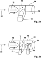
- Figure 2a shows a first example of a pipe section 24 through which a fluid 10 flows in a flow direction 22.
- a single measuring plane 14 is shown, which forms a measuring plane, with the main flow direction 22 lying in the measuring plane.
- the measuring plane 14 is formed by a light source, not shown, for external irradiation of light within the flow volume in the pipe section 24.
- the pipe section 24 has, for example, a light-transparent wall area.
- Particles 13 are present in the fluid 10 and are detected by the sensor unit 12 within the measuring planes 14. The movement of the particles 13 is recorded both in the flow direction 22 and transversely to the flow direction 22 within the measuring plane 14.
- Figure 2b shows a view of the pipe section 24 through which the fluid 10 flows in the flow direction 22, and the arrangement has a first measuring plane 14 and a downstream second measuring plane 14, wherein a first sensor unit 12 is assigned to the first measuring plane 14 and a further sensor unit 12 is assigned to the second measuring plane 14.
- the measuring planes 14 are arranged offset by 90° to one another, wherein in each of the measuring planes 14 the flow direction 22 lies as a vector in the plane.
- the sensor unit 12 can be designed two-dimensionally or several light sections can be provided which have different wavelengths that are offset in time, in particular pulsed or spatially separated from one another. This results in the particular advantage that asymmetrical flow profiles can be measured, so that the downstream FPGA 15 can process the movement vectors of the particles 13 into velocity information of the fluid 10 in the pipe cross-section 24.
- Figure 3 represents a special variant of a flow measuring device 1, and the pipe section 24 is shown in a front view for illustration purposes and has the fluid 10 flowing through it. Particles 13 are located in the fluid 10, with one particle 13 being shown as an example.
- the wall of the pipe section 24 is designed to be transparent, for example, in order to radiate light by means of the light sources 11.
- the arrangement has a first light source 11 and a second light source 11 arranged within the pipe section 24 offset by 90° around its longitudinal axis. Both light sources 11 thus radiate light into the fluid 10 perpendicular to one another, resulting in two measuring planes 14 whose measuring planes are arranged perpendicular to one another.
- the Sensor unit 12 In the bisector between the extension planes of the two measuring planes 14, the Sensor unit 12, so that the observation directions 23 each enclose an angle of 135° to both light propagation directions of the light sources 11. If the flow measuring device 1 is operated and the light sources 11 emit corresponding light, which is received by the sensor unit 12 as scattered light formed on the particle 13, measurements can be taken in two measuring planes 14 with one sensor unit 12.
- Figure 4 shows, by way of example, particles 13 moving in the flow direction 22.
- a light source (not shown in detail) is used to generate scattered light, which first passes through a cylindrical lens array line sensor arrangement 21, whereby the movement of the particles 13 can be detected with the line sensors of the line sensor arrangement.
- photodiodes 20 can be used, which are also shown in the Figure 4 are shown.
- the scattered light alternately reaches the photodiodes 20 shown through the cylindrical lens array, so that a movement of the particles 13 can also be detected.
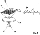
- Figure 5 shows a sensor unit 12, which is designed, for example, as a CMOS sensor 19. If the particles 13 shown as an example move below a lens 25, the individual pixels of the CMOS sensor 19 are illuminated one after the other by means of a light source (not shown) and scattered light generated on the particles 13, so that the backscattered light and the exposure of the CMOS sensor 19 cause a Signal S is generated over time t, which has a waveform. The more particles 13 there are in the fluid, the greater the amplitude of the signal S, whereby a speed of movement and a direction of movement of the particles 13 can be detected over time t.
- a light source not shown
- CMOS sensor 19 Due to the two-dimensionality of the CMOS sensor 19, a movement of the particles 13 in the fluid can occur both in the flow direction 22 and transversely Flow direction 22 can be detected, which is then done with the FPGA 15 (see Figure 1 ) can be reconstructed into a fully reconstructed digitally provided flow profile.
Claims (10)
- Procédé de mesure de débit destiné à la mesure optique de paramètres d'écoulement variables dans le temps d'un fluide (10) s'écoulant à travers une section transversale fermée, au moyen d'au moins une source de lumière (11) et d'au moins un ensemble capteur (12) permettant de détecter des particules (13) présentes dans le fluide (10) dans un plan de mesure (14), dans lequel- au moins un plan de mesure et les particules (13) présentes dans celui-ci sont éclairés au moyen de la source de lumière (11), dans lequel- les particules sont représentées sur l'ensemble capteur (12) et caractérisé en ce que- l'ensemble capteur (12) présente un détecteur CMOS à matrice (19) doté d'un FPGA (15) directement raccordé et l'ensemble capteur (12) étant pourvu d'au moins deux ou d'une pluralité de détecteurs individuels (12a, 12b, 12c, 12b) au moyen desquels des signaux de capteur (S) concernant des points d'image et/ou lignes d'image sont fournis en sortie, et en ce que- les signaux de capteur (S) concernant des points d'image et/ou lignes d'image sont convertis en continu et en temps réel, sans mémorisation temporaire, par technologie de filtrage spatial en au moins un profil de vitesse au moyen de l'ensemble capteur (12),- l'ensemble capteur (12) fournit en sortie, en continu et en temps réel, à partir du profil de vitesse dépendant du temps, des paramètres d'écoulement, comprenant au moins deux des paramètres suivants : débit volumétrique, débit massique cumulé, profil d'écoulement, état d'écoulement turbulent/laminaire, degré de turbulence, spectre de turbulence, écoulement giratoire,- l'ensemble capteur (12) calcule et fournit en sortie, en continu, en temps réel et avec résolution temporelle, un ou plusieurs paramètres d'état d'écoulement intégraux,- dans lequel un ensemble de calcul (16) est placé en aval de l'ensemble capteur (12) et du réseau de portes programmable par l'utilisateur (15), ledit ensemble de calcul permettant de traiter les profils de vitesse sur la base de l'intégration et de la pondération des points d'image et/ou lignes d'image par le FPGA (15) comme paramètres d'écoulement intégraux par l'ensemble de calcul (16) et de les émettre sous la forme d'un signal de sortie (18) à partir d'un module de sortie (17).
- Procédé de mesure de débit selon la revendication 1,
caractérisé en ce que
un réseau de portes programmable par l'utilisateur (15) est placé entre l'ensemble capteur (12) et l'ensemble de calcul (16), ledit réseau de portes programmable par l'utilisateur étant exploité avec une configuration de programme au moyen de laquelle, à partir des points d'image et/ou lignes d'image détectés par l'ensemble capteur (12), des vecteurs de mouvement des particules (13) et ainsi du fluide (10) sont générées sur la base des particules (13) déplacées. - Procédé de mesure de débit selon la revendication 2,
caractérisé en ce que
le module de sortie (17) est placé en aval de l'ensemble de calcul (16), les vecteurs de mouvement des particules (13) et ainsi du fluide (10) étant fournis en sortie par l'ensemble de calcul (16) sur ledit module de sortie et une vitesse d'écoulement du fluide (10) étant fournie en sortie comme signal de sortie (18) sur la base des vecteurs de mouvement des particules (13) au moyen dudit module de sortie. - Procédé de mesure de débit selon l'une des revendications 1 à 3, caractérisé en ce que
l'ensemble capteur (12) est conçu au moyen d'au moins un capteur CMOS (19) et/ou un capteur CCD et/ou un agencement de photodiodes (20). - Procédé de mesure de débit selon l'une des revendications précédentes, caractérisé en ce que
un premier ensemble capteur (12) est associé à un premier plan de mesure (14) et un second ensemble capteur (12) à un second plan de mesure (14), les au moins deux plans de mesure (14) étant réalisés l'un derrière l'autre dans le sens d'écoulement (22) du fluide. - Procédé de mesure de débit selon la revendication 5,
caractérisé en ce que
le sens d'observation (23) de l'ensemble capteur (12) est configuré avec un décalage angulaire dans le sens opposé à la direction d'émission d'une lumière d'une source de lumière (11). - Procédé de mesure de débit selon l'une des revendications précédentes, caractérisé en ce que
au moins deux sources de lumière (11) sont agencées de telle manière l'une par rapport à l'autre et par rapport à l'ensemble capteur (12) qu'au moins deux plans de mesure (14) avec une ligne d'intersection commune ou situés l'un derrière l'autre dans le sens d'écoulement sont créés et détectés par un seul ensemble capteur (12). - Procédé de mesure de débit selon l'une des revendications précédentes, caractérisé en ce que
deux plans de mesure (14) sont formés, lesquels sont orientés parallèlement l'un à l'autre, perpendiculairement l'un à l'autre ou avec un décalage angulaire compris entre 60° et 180° et en particulier de 90° l'un par rapport à l'autre. - Procédé de mesure de débit selon l'une des revendications précédentes, caractérisé en ce que
l'au moins une source de lumière (11) émet de la lumière continue ou pulsée et/ou en ce que l'au moins une source de lumière (11) émet de la lumière avec des longueurs d'onde différentes les unes des autres. - Dispositif de mesure de débit (1) destiné à exécuter un procédé de mesure de débit selon l'une des revendications précédentes, comportant au moins : - une partie de tuyau (24) dans laquelle un fluide (10) peut circuler, - au moins une source de lumière (11) au moyen de laquelle de la lumière peut être irradiée dans la partie de tuyau (24) et au moyen de laquelle les particules (13) présentes dans le fluide (10) peuvent être éclairées dans au moins un plan de mesure, - au moins un ensemble capteur (12) au moyen duquel des particules (13) présentes dans le fluide (10) dans un plan de mesure (14) peuvent être détectées, l'ensemble capteur (12) présentant un détecteur CMOS à matrice (19) doté d'un FPGA (15) directement raccordé qui peut être exploité avec une configuration de programme au moyen de laquelle, à partir de points d'image et/ou lignes d'image détectés par l'ensemble capteur (12), des vecteurs de mouvement des particules (13) et ainsi du fluide (10) peuvent être générés sur la base des particules (13) déplacées, et l'ensemble capteur (12) présentant au moins deux ou une pluralité de détecteurs individuels (12a, 12b, 12c, 12b), au moyen desquels des signaux de capteur (S) concernant des points d'image et/ou lignes d'image peuvent être fournis en sortie, - un ensemble de calcul (16) étant placé en aval de l'ensemble capteur (12) et du réseau de portes programmable par l'utilisateur (15), ledit ensemble de calcul (16) permettant de traiter les profils de vitesse sur la base de l'intégration et de la pondération des points d'image et/ou lignes d'image par le FPGA (15) sous la forme de paramètres d'écoulement intégraux et de les fournir en sortie sous la forme d'un signal de sortie (18) par un module de sortie (17
Applications Claiming Priority (1)
| Application Number | Priority Date | Filing Date | Title |
|---|---|---|---|
| DE102018131059.5A DE102018131059A1 (de) | 2018-12-05 | 2018-12-05 | Strömungsmessverfahren und Strömungsmessvorrichtung zur optischen Strömungsmessung |
Publications (2)
| Publication Number | Publication Date |
|---|---|
| EP3663727A1 EP3663727A1 (fr) | 2020-06-10 |
| EP3663727B1 true EP3663727B1 (fr) | 2024-04-03 |
Family
ID=67840969
Family Applications (1)
| Application Number | Title | Priority Date | Filing Date |
|---|---|---|---|
| EP19194877.7A Active EP3663727B1 (fr) | 2018-12-05 | 2019-09-02 | Procédé de mesure de débit et dispositif de mesure de débit destiné à la mesure optique de débit |
Country Status (6)
| Country | Link |
|---|---|
| US (1) | US11002583B2 (fr) |
| EP (1) | EP3663727B1 (fr) |
| JP (1) | JP6909273B2 (fr) |
| KR (1) | KR102279338B1 (fr) |
| CN (1) | CN111273054A (fr) |
| DE (1) | DE102018131059A1 (fr) |
Family Cites Families (43)
| Publication number | Priority date | Publication date | Assignee | Title |
|---|---|---|---|---|
| US3547540A (en) * | 1967-12-15 | 1970-12-15 | Nasa | Laser fluid velocity detector |
| CH521590A (de) * | 1970-09-25 | 1972-04-15 | Bbc Brown Boveri & Cie | Verfahren und Einrichtung zur Messung der Periodendauer eines elektrischen Signals mit statistisch schwänkenden Signalamplituden |
| US5701172A (en) * | 1995-06-07 | 1997-12-23 | Gas Research Institute | Optical flowmeter |
| US6369881B1 (en) * | 2000-05-19 | 2002-04-09 | Optical Scientific, Inc. | Optical flow sensor |
| JP2001356130A (ja) * | 2000-06-15 | 2001-12-26 | Matsushita Electric Ind Co Ltd | 液流または噴射流可視化装置 |
| WO2002025934A2 (fr) * | 2000-09-25 | 2002-03-28 | Sensovation Ag | Dispositif de detection d'images, appareil et procede de mesures optiques |
| JP2003056826A (ja) * | 2001-08-20 | 2003-02-26 | Takuma Co Ltd | ストーカ式ごみ焼却炉 |
| DE10312696B3 (de) * | 2003-03-21 | 2004-12-23 | Lavision Gmbh | Verfahren zur Bestimmung der Abbildungsgleichung für die Selbstkalibrierung in Bezug auf die Durchführung von Stereo-PIV-Verfahren |
| CA2439242C (fr) | 2003-09-03 | 2008-01-29 | Photon Control Inc. | Debitmetre optique pour mesurer la vitesse des gaz et des liquides dans les pipelines |
| EP1862780A4 (fr) * | 2005-03-23 | 2008-12-31 | Ohm Electric Co Ltd | Dispositif et procede d observation d un etat fluidise |
| US7456960B2 (en) * | 2005-06-06 | 2008-11-25 | Particle Measuring Systems, Inc. | Particle counter with improved image sensor array |
| DE102005042954B4 (de) | 2005-09-05 | 2007-07-12 | Technische Universität Dresden | Vorrichtung und Verfahren zur Bestimmung von Geschwindigkeitsprofilen in beliebig gerichteten Strömungen |
| DE102006039489B3 (de) | 2006-08-21 | 2008-01-31 | B.R. Deutschland, vertr. d. d. Bundesministerium f. Wirtschaft u.Technologie, dieses vertr. d. d. Präs. d. Phys.-Techn. Bundesanstalt | Verfahren zur Messung von Geschwindigkeitsverteilungen eines durch einen Rohrquerschnitt strömenden Fluids und Messanordnung zur Durchführung des Verfahrens |
| US7738084B1 (en) * | 2006-09-29 | 2010-06-15 | The United States Of America As Represented By The Administrator Of The National Aeronautics And Space Administration | Fiber optic liquid mass flow sensor and method |
| ATE466258T1 (de) * | 2007-07-28 | 2010-05-15 | Sika Dr Siebert & Kuehn Gmbh & | Vorrichtung zur überwachung des durchflusses eines mediums in einer durchflusseinrichtung |
| AT505522B1 (de) * | 2007-08-09 | 2011-04-15 | Univ Graz Tech | Vorrichtung zum bestimmen von strömungsparametern einer partikel - fluidum - strömung |
| DE102007040970B3 (de) | 2007-08-28 | 2009-04-16 | Bundesrepublik Deutschland, vertr.d.d. Bundesministerium für Wirtschaft und Technologie, d.vertr.d.d. Präsidenten der Physikalisch-Technischen Bundesanstalt | Messverfahren und Messanordnung zum Ermitteln eines Volumenstroms eines Fluids in einer Rohrleitung |
| DE102009005800A1 (de) | 2009-01-22 | 2010-07-29 | Dues, Michael, Dr.-Ing. | Optische Strömungsmessung |
| WO2010104993A2 (fr) * | 2009-03-10 | 2010-09-16 | The Regents Of The University Of California | Dispositifs de cytométrie de flux fluidiques et détection de particules basée sur le codage de signaux |
| US20100235117A1 (en) * | 2009-03-15 | 2010-09-16 | Lauris Technologies Inc | Optical Gas Flow Meter |
| DE102009047198A1 (de) * | 2009-11-26 | 2011-06-01 | Universität Rostock | Mikroarraybasiertes Ortsfilter |
| EP2333515A1 (fr) * | 2009-12-11 | 2011-06-15 | Bayer Technology Services GmbH | Moyen de détection de particules luminescentes et/ou diffusant de la lumière dans des liquides s'écoulant |
| CN101738489B (zh) * | 2009-12-16 | 2012-01-11 | 清华大学深圳研究生院 | 一种测量散射性流体横向流速的方法 |
| DE102010030835B4 (de) | 2010-07-01 | 2012-12-20 | Universität Rostock | Verfahren und Vorrichtung zur Ortsfiltermessung |
| US8522624B2 (en) | 2011-03-02 | 2013-09-03 | Cameron International Corporation | System and method for pressure balancing a flow meter |
| AT511200B1 (de) * | 2011-10-20 | 2012-10-15 | Isiqiri Interface Tech Gmbh | Echtzeitmessung von relativen positionsdaten und/oder von geometrischen massen eines bewegten körpers unter verwendung optischer messmittel |
| US8830476B2 (en) * | 2012-03-19 | 2014-09-09 | The United States Of America As Represented By The Secretary Of The Army | Methods and apparatuses for contact-free holographic imaging of aerosol particles |
| WO2014173442A1 (fr) * | 2013-04-24 | 2014-10-30 | Schöttler Markus | Dispositif et procédé de détection optique de mouvements d'écoulement dans des milieux liquides et/ou gazeux |
| CN103472255B (zh) * | 2013-09-16 | 2017-01-18 | 南京牧镭激光科技有限公司 | 全光纤多普勒相干激光雷达风速测量装置 |
| CN103472256B (zh) * | 2013-09-25 | 2015-09-16 | 东南大学 | 基于面阵ccd空间滤波器的流动二维速度场测量方法及装置 |
| DE102014205882B3 (de) | 2014-03-28 | 2015-08-27 | Bundesrepublik Deutschland, vertr. durch das Bundesministerium für Wirtschaft und Energie, dieses vertreten durch den Präsidenten der Physikalisch-Technischen Bundesanstalt | Laser-Durchflussmessgerät und Verfahren zum Kalibrieren eines Laser-Durchflussmessgeräts |
| WO2016037236A1 (fr) * | 2014-09-11 | 2016-03-17 | 21 Century Products Limited | Procédé et appareil pour vélocimétrie par suivi d'éléments de trajectoire de particule |
| WO2016054293A1 (fr) * | 2014-09-30 | 2016-04-07 | The Regents Of The University Of California | Cytomètre de flux à imagerie utilisant une transformation spatio-temporelle |
| DE102015001826B3 (de) | 2015-02-16 | 2016-03-31 | Bundesrepublik Deutschland, vertr. durch das Bundesministerium für Wirtschaft und Energie, dieses vertreten durch den Präsidenten der Physikalisch-Technischen Bundesanstalt | Armatur |
| JP2016182842A (ja) * | 2015-03-25 | 2016-10-20 | トヨタ自動車株式会社 | ハイブリッド車両の制御装置 |
| US10613096B2 (en) * | 2015-08-28 | 2020-04-07 | Captl Llc | Multi-spectral microparticle-fluorescence photon cytometry |
| DE102015217022A1 (de) * | 2015-09-04 | 2017-03-09 | Universität Rostock | Ortsfiltermessverfahren und Vorrichtung zur Ortsfiltermessung |
| US10900987B2 (en) * | 2015-11-10 | 2021-01-26 | The Johns Hopkins University | Robust particle velocity measurement |
| US10379136B2 (en) * | 2015-12-10 | 2019-08-13 | Mitsubishi Electric Corporation | Laser radar device |
| KR20180101086A (ko) | 2017-03-03 | 2018-09-12 | 김태용 | 수질측정장치 |
| CN109688837B (zh) * | 2016-09-20 | 2022-08-09 | 日本水产株式会社 | 除去了异物的鱼子酱的制造方法和除去了异物的鱼子酱的制造装置 |
| CN206193021U (zh) * | 2016-11-10 | 2017-05-24 | 华东师范大学 | 一种基于数字微镜的空间滤波测速装置 |
| CN108344879A (zh) * | 2018-02-05 | 2018-07-31 | 上海理工大学 | 泥石流表面速度场分布的非接触测量装置及其测量方法 |
-
2018
- 2018-12-05 DE DE102018131059.5A patent/DE102018131059A1/de active Pending
-
2019
- 2019-09-02 EP EP19194877.7A patent/EP3663727B1/fr active Active
- 2019-10-18 CN CN201910995869.7A patent/CN111273054A/zh active Pending
- 2019-11-26 JP JP2019212869A patent/JP6909273B2/ja active Active
- 2019-12-02 KR KR1020190157908A patent/KR102279338B1/ko active IP Right Grant
- 2019-12-04 US US16/703,335 patent/US11002583B2/en active Active
Non-Patent Citations (1)
| Title |
|---|
| MOTOFUMI KOBATAKE ET AL: "A real-time micro-PIV system using frame-straddling high-speed vision", ROBOTICS AND AUTOMATION (ICRA), 2012 IEEE INTERNATIONAL CONFERENCE ON, IEEE, 14 May 2012 (2012-05-14), pages 397 - 402, XP032450552, ISBN: 978-1-4673-1403-9, DOI: 10.1109/ICRA.2012.6224821 * |
Also Published As
| Publication number | Publication date |
|---|---|
| DE102018131059A1 (de) | 2020-06-10 |
| JP2020091284A (ja) | 2020-06-11 |
| CN111273054A (zh) | 2020-06-12 |
| US20200182671A1 (en) | 2020-06-11 |
| KR20200069233A (ko) | 2020-06-16 |
| EP3663727A1 (fr) | 2020-06-10 |
| JP6909273B2 (ja) | 2021-07-28 |
| US11002583B2 (en) | 2021-05-11 |
| KR102279338B1 (ko) | 2021-07-20 |
Similar Documents
| Publication | Publication Date | Title |
|---|---|---|
| EP3479096B1 (fr) | Procédé permettant de déterminer par dispersion dynamique de la lumière la taille moyenne de particules en suspension dans un milieu liquide ou fluide, et dispositif afférent | |
| DE102009014080A1 (de) | Vorrichtung zum Bestimmen von Partikelgrössen | |
| DE102012102363A1 (de) | Verfahren und Vorrichtung zur Bestimmung der Größe eines transparenten Teilchens | |
| DE3504622A1 (de) | Anordnung zur beruehrungslosen messung der geschwindigkeit eines bewegten mediums | |
| DE102014011480B3 (de) | Verfahren zum Kalibrieren eines Teilchenbild-Velozimeters und Teilchenbild-Velozimeter | |
| DE60036467T2 (de) | Verfahren und vorrichtung zur dopplergeschwindigkeitsmessung | |
| DE19954702A1 (de) | Planares-Interferenz-Partikelgrößenmeßgerät | |
| DE102009060580B4 (de) | Verfahren zur Bestimmung eines Satzes von optischen Abbildungsfunktionen für die 3D-Strömungsmessung | |
| DE102011101384A1 (de) | Verfahren zur Bestimmung der zeitlichen und/oder räumlichen Partikelgrößenverteilung in einem Fluidvolumen | |
| DE102011009675B4 (de) | Verfahren zur Bestimmung von Geschwindigkeiten in Strömungen und Phasen-Frequenz-Gechwindigkeits-Feldsensor | |
| EP3663727B1 (fr) | Procédé de mesure de débit et dispositif de mesure de débit destiné à la mesure optique de débit | |
| DE102010049673B4 (de) | Vorrichtung und Verfahren zur 3D-Bestimmung von Geschwindigkeitsprofilen transparenter fluider Strömungen | |
| DE4321876C1 (de) | Verfahren und Vorrichtung zur Erzeugung einer graphischen Echtzeit-Richtungsinformation für detektierte Objektspuren | |
| DE102005028893B4 (de) | Vorrichtung zur Partikeldetektion in einer tiefenbegrenzten Lichtscheibe | |
| CN115901178A (zh) | 多体海工结构间波浪共振流场特性的测量系统和分析方法 | |
| DE102010030835B4 (de) | Verfahren und Vorrichtung zur Ortsfiltermessung | |
| DE202008003245U1 (de) | Vorrichtung zur Ultraschall-Messung von Blutfluß | |
| DE102006047286B4 (de) | Verfahren zum Bestimmen von lokalen Strömungsgeschwindigkeiten eines Fluids | |
| DE102012214897B3 (de) | Verfahren zur planaren Bestimmung von Zustandsgrößen einer Fluidströmung sowie Messvorrichtung | |
| DE60110341T2 (de) | Anordnung und Verfahren zur Entfernungsmessung | |
| DE102018117776B4 (de) | Vorrichtung zur Ermittlung einer Geschwindigkeitskomponente eines Objekts | |
| DE102018131990A1 (de) | Verfahren und Vorrichtung zur tiefenauflösenden Ortsfiltermessung | |
| DE102017009334B3 (de) | Verfahren zum Prüfen eines optischen Systems | |
| DE4102855C2 (de) | Verfahren und Vorrichtung zur Bestimmung von lokalen Dichteschwankungen in Grenzschichten eines umströmten Körpers | |
| DE102005056409B3 (de) | Verfahren zur Bestimmung des Geschwindigkeitsfeldes in bewegten gasförmigen oder flüssigen Medien mit Hilfe von in das Medium eigebrachten Teilchen |
Legal Events
| Date | Code | Title | Description |
|---|---|---|---|
| PUAI | Public reference made under article 153(3) epc to a published international application that has entered the european phase |
Free format text: ORIGINAL CODE: 0009012 |
|
| STAA | Information on the status of an ep patent application or granted ep patent |
Free format text: STATUS: THE APPLICATION HAS BEEN PUBLISHED |
|
| AK | Designated contracting states |
Kind code of ref document: A1 Designated state(s): AL AT BE BG CH CY CZ DE DK EE ES FI FR GB GR HR HU IE IS IT LI LT LU LV MC MK MT NL NO PL PT RO RS SE SI SK SM TR |
|
| AX | Request for extension of the european patent |
Extension state: BA ME |
|
| STAA | Information on the status of an ep patent application or granted ep patent |
Free format text: STATUS: REQUEST FOR EXAMINATION WAS MADE |
|
| 17P | Request for examination filed |
Effective date: 20201125 |
|
| RBV | Designated contracting states (corrected) |
Designated state(s): AL AT BE BG CH CY CZ DE DK EE ES FI FR GB GR HR HU IE IS IT LI LT LU LV MC MK MT NL NO PL PT RO RS SE SI SK SM TR |
|
| STAA | Information on the status of an ep patent application or granted ep patent |
Free format text: STATUS: EXAMINATION IS IN PROGRESS |
|
| 17Q | First examination report despatched |
Effective date: 20220426 |
|
| REG | Reference to a national code |
Ref document number: 502019010949 Country of ref document: DE Ref country code: DE Ref legal event code: R079 Free format text: PREVIOUS MAIN CLASS: G01F0001660000 Ipc: G01F0001661000 |
|
| GRAP | Despatch of communication of intention to grant a patent |
Free format text: ORIGINAL CODE: EPIDOSNIGR1 |
|
| STAA | Information on the status of an ep patent application or granted ep patent |
Free format text: STATUS: GRANT OF PATENT IS INTENDED |
|
| RIC1 | Information provided on ipc code assigned before grant |
Ipc: G01F 1/66 20060101ALI20231027BHEP Ipc: G01F 1/7086 20220101ALI20231027BHEP Ipc: G01F 1/661 20220101AFI20231027BHEP |
|
| INTG | Intention to grant announced |
Effective date: 20231116 |
|
| GRAS | Grant fee paid |
Free format text: ORIGINAL CODE: EPIDOSNIGR3 |
|
| GRAA | (expected) grant |
Free format text: ORIGINAL CODE: 0009210 |
|
| STAA | Information on the status of an ep patent application or granted ep patent |
Free format text: STATUS: THE PATENT HAS BEEN GRANTED |
|
| AK | Designated contracting states |
Kind code of ref document: B1 Designated state(s): AL AT BE BG CH CY CZ DE DK EE ES FI FR GB GR HR HU IE IS IT LI LT LU LV MC MK MT NL NO PL PT RO RS SE SI SK SM TR |
|
| REG | Reference to a national code |
Ref country code: CH Ref legal event code: EP |
|
| REG | Reference to a national code |
Ref country code: DE Ref legal event code: R096 Ref document number: 502019010949 Country of ref document: DE |