EP3663727B1 - Flow measuring method and flow measuring device for optical flow measurement - Google Patents
Flow measuring method and flow measuring device for optical flow measurement Download PDFInfo
- Publication number
- EP3663727B1 EP3663727B1 EP19194877.7A EP19194877A EP3663727B1 EP 3663727 B1 EP3663727 B1 EP 3663727B1 EP 19194877 A EP19194877 A EP 19194877A EP 3663727 B1 EP3663727 B1 EP 3663727B1
- Authority
- EP
- European Patent Office
- Prior art keywords
- flow
- sensor unit
- fluid
- particles
- sensor
- Prior art date
- Legal status (The legal status is an assumption and is not a legal conclusion. Google has not performed a legal analysis and makes no representation as to the accuracy of the status listed.)
- Active
Links
- 238000000034 method Methods 0.000 title claims description 66
- 238000005259 measurement Methods 0.000 title claims description 40
- 230000003287 optical effect Effects 0.000 title claims description 20
- 239000012530 fluid Substances 0.000 claims description 67
- 239000002245 particle Substances 0.000 claims description 51
- 230000033001 locomotion Effects 0.000 claims description 26
- 239000013598 vector Substances 0.000 claims description 18
- 238000005516 engineering process Methods 0.000 claims description 10
- 230000010354 integration Effects 0.000 claims description 10
- 238000012545 processing Methods 0.000 claims description 8
- 238000001914 filtration Methods 0.000 claims description 6
- 238000001228 spectrum Methods 0.000 claims description 2
- 230000036962 time dependent Effects 0.000 claims description 2
- 230000003139 buffering effect Effects 0.000 claims 1
- 238000000917 particle-image velocimetry Methods 0.000 description 14
- 230000008901 benefit Effects 0.000 description 12
- 230000008569 process Effects 0.000 description 8
- 238000003384 imaging method Methods 0.000 description 6
- 238000000691 measurement method Methods 0.000 description 6
- 230000008878 coupling Effects 0.000 description 5
- 238000010168 coupling process Methods 0.000 description 5
- 238000005859 coupling reaction Methods 0.000 description 5
- 238000001514 detection method Methods 0.000 description 4
- 238000003491 array Methods 0.000 description 3
- 238000006243 chemical reaction Methods 0.000 description 3
- 238000005286 illumination Methods 0.000 description 3
- 230000001427 coherent effect Effects 0.000 description 2
- 238000011109 contamination Methods 0.000 description 2
- 238000013461 design Methods 0.000 description 2
- 238000011156 evaluation Methods 0.000 description 2
- 230000003993 interaction Effects 0.000 description 2
- 238000012423 maintenance Methods 0.000 description 2
- 238000000037 particle-tracking velocimetry Methods 0.000 description 2
- 230000002123 temporal effect Effects 0.000 description 2
- 230000009471 action Effects 0.000 description 1
- 230000003044 adaptive effect Effects 0.000 description 1
- 210000004369 blood Anatomy 0.000 description 1
- 239000008280 blood Substances 0.000 description 1
- 239000003086 colorant Substances 0.000 description 1
- 238000010276 construction Methods 0.000 description 1
- 238000012937 correction Methods 0.000 description 1
- 230000001186 cumulative effect Effects 0.000 description 1
- 230000001419 dependent effect Effects 0.000 description 1
- 238000011161 development Methods 0.000 description 1
- 230000018109 developmental process Effects 0.000 description 1
- 210000003743 erythrocyte Anatomy 0.000 description 1
- 239000011521 glass Substances 0.000 description 1
- 238000009434 installation Methods 0.000 description 1
- 238000012432 intermediate storage Methods 0.000 description 1
- 239000007788 liquid Substances 0.000 description 1
- 239000011159 matrix material Substances 0.000 description 1
- 230000004089 microcirculation Effects 0.000 description 1
- 238000001208 nuclear magnetic resonance pulse sequence Methods 0.000 description 1
- 230000005855 radiation Effects 0.000 description 1
- 230000009467 reduction Effects 0.000 description 1
- 239000008399 tap water Substances 0.000 description 1
- 235000020679 tap water Nutrition 0.000 description 1
- 238000000827 velocimetry Methods 0.000 description 1
Images


Classifications
-
- G—PHYSICS
- G01—MEASURING; TESTING
- G01F—MEASURING VOLUME, VOLUME FLOW, MASS FLOW OR LIQUID LEVEL; METERING BY VOLUME
- G01F1/00—Measuring the volume flow or mass flow of fluid or fluent solid material wherein the fluid passes through a meter in a continuous flow
- G01F1/66—Measuring the volume flow or mass flow of fluid or fluent solid material wherein the fluid passes through a meter in a continuous flow by measuring frequency, phase shift or propagation time of electromagnetic or other waves, e.g. using ultrasonic flowmeters
- G01F1/661—Measuring the volume flow or mass flow of fluid or fluent solid material wherein the fluid passes through a meter in a continuous flow by measuring frequency, phase shift or propagation time of electromagnetic or other waves, e.g. using ultrasonic flowmeters using light
-
- G—PHYSICS
- G01—MEASURING; TESTING
- G01F—MEASURING VOLUME, VOLUME FLOW, MASS FLOW OR LIQUID LEVEL; METERING BY VOLUME
- G01F1/00—Measuring the volume flow or mass flow of fluid or fluent solid material wherein the fluid passes through a meter in a continuous flow
- G01F1/704—Measuring the volume flow or mass flow of fluid or fluent solid material wherein the fluid passes through a meter in a continuous flow using marked regions or existing inhomogeneities within the fluid stream, e.g. statistically occurring variations in a fluid parameter
- G01F1/708—Measuring the time taken to traverse a fixed distance
- G01F1/7086—Measuring the time taken to traverse a fixed distance using optical detecting arrangements
-
- G—PHYSICS
- G01—MEASURING; TESTING
- G01F—MEASURING VOLUME, VOLUME FLOW, MASS FLOW OR LIQUID LEVEL; METERING BY VOLUME
- G01F1/00—Measuring the volume flow or mass flow of fluid or fluent solid material wherein the fluid passes through a meter in a continuous flow
- G01F1/66—Measuring the volume flow or mass flow of fluid or fluent solid material wherein the fluid passes through a meter in a continuous flow by measuring frequency, phase shift or propagation time of electromagnetic or other waves, e.g. using ultrasonic flowmeters
- G01F1/662—Constructional details
-
- G—PHYSICS
- G01—MEASURING; TESTING
- G01F—MEASURING VOLUME, VOLUME FLOW, MASS FLOW OR LIQUID LEVEL; METERING BY VOLUME
- G01F5/00—Measuring a proportion of the volume flow
-
- G—PHYSICS
- G01—MEASURING; TESTING
- G01N—INVESTIGATING OR ANALYSING MATERIALS BY DETERMINING THEIR CHEMICAL OR PHYSICAL PROPERTIES
- G01N15/00—Investigating characteristics of particles; Investigating permeability, pore-volume, or surface-area of porous materials
- G01N15/02—Investigating particle size or size distribution
- G01N15/0205—Investigating particle size or size distribution by optical means, e.g. by light scattering, diffraction, holography or imaging
-
- G—PHYSICS
- G01—MEASURING; TESTING
- G01P—MEASURING LINEAR OR ANGULAR SPEED, ACCELERATION, DECELERATION, OR SHOCK; INDICATING PRESENCE, ABSENCE, OR DIRECTION, OF MOVEMENT
- G01P5/00—Measuring speed of fluids, e.g. of air stream; Measuring speed of bodies relative to fluids, e.g. of ship, of aircraft
- G01P5/26—Measuring speed of fluids, e.g. of air stream; Measuring speed of bodies relative to fluids, e.g. of ship, of aircraft by measuring the direct influence of the streaming fluid on the properties of a detecting optical wave
-
- G—PHYSICS
- G01—MEASURING; TESTING
- G01N—INVESTIGATING OR ANALYSING MATERIALS BY DETERMINING THEIR CHEMICAL OR PHYSICAL PROPERTIES
- G01N15/00—Investigating characteristics of particles; Investigating permeability, pore-volume, or surface-area of porous materials
- G01N15/02—Investigating particle size or size distribution
- G01N2015/0294—Particle shape
Definitions
- the invention relates to a flow measuring method for the optical measurement of time-changing flow parameters of a fluid flowing through a closed cross section and a flow measuring device for this purpose, with at least one light source and with at least one sensor unit, with which particles present in the fluid are detected within a measuring plane.
- Non-invasive methods for measuring flow do not disturb the flow of the fluid in the pipe section, as is the case with the use of sensors in the flow, so non-invasive measuring methods are preferable in principle.
- With non-invasive methods for measuring the flow rate of a fluid there is therefore no mechanical interaction or coupling with the fluid, but the measurement effort can be significantly greater than with a flow measurement using mechanical interaction, for example a sensor that protrudes into the flowing fluid.
- Non-invasive flow and volume flow measurement methods that can currently be used in processes are based on different operating principles. Acoustic methods can be used without modifying the pipe, but only provide an integral value. Coriolis methods determine the integral mass flow. Magnetic-inductive methods require a conductive liquid. A process-compatible optical sensor principle for determining the flow or volume flow has not yet been implemented and is also not known in the literature. Flow and volume flow measurements based on a flow profile in a pipe require the continuous, time-resolved and real-time measurement of this flow profile. The currently known optical flow measurement techniques for determining the volume flow cannot determine the flow profile in a pipe section in real time, continuously with time resolution and with comparatively little hardware effort.
- Optical methods for measuring flow are based on the radiation of electromagnetic waves, in particular light, into the fluid, for example when it flows through the pipe section. Basically, a distinction can be made between point-based measuring methods, integral measuring methods and spatially resolving measuring methods.
- An example of a point measurement method is the laser Doppler technique. Only a locally very limited area can be measured, and due to the small resulting measuring range, only an imprecise indication of the total volume flow of the fluid can be made. This particularly applies to flows with pronounced or even dynamically changing flow profiles. Volume flow measurements using laser Doppler technology are typically carried out for stationary flows by scanning the profile.
- the laser Doppler technique was developed in EN 10 2005 042 954 A1 for the spatially resolving determination of flow profiles.
- the profile sensor described here requires a great deal of effort for implementation, adjustment and coupling of the superimposed divergent interference fringe structures.
- the interference structure must also be adapted to the process optically and/or mechanically.
- the laser Doppler technology always requires coherent light and thus a laser beam source.
- the sensor cannot measure directly through curved surfaces, as this would disturb the interference pattern.
- An integral method is the optical transit time or correlation flow meter, for example from the CA 2 439 242 A1 is known. This process integrates the signal across the entire flow profile. The conversion into a volume flow requires a complex process Model assumption for the flow profile. Speed-related or installation-related flow profile changes disadvantageously reduce the measurement accuracy and/or the dynamic range.
- a well-known optical measuring method for determining the spatially resolved flow velocity of a fluid is so-called particle image velocimetry. This determines the local two-dimensional offset of particles present and imaged in the flow. The offset estimate is based either on cross-correlation (particle image velocimetry, PIV for short) or on tracking of image features (particle tracking velocimetry, PTV for short). Due to the very high computing power required for evaluating the image data and determining the local velocity vectors, continuous real-time measurement of the flow velocity of a fluid is not easily possible. The measuring technology required for this, in particular the hardware for providing high computing power, is very cost-intensive.
- particle image velocimetry requires uniform focusing of the image.
- volume flow measurements in, for example, round pipes and/or for oblique observation directions sufficient homogeneity of the focusing is not given and the image quality changes locally.
- particle image velocimetry uses so-called Scheimflug arrangements. These are rather complex in terms of opto-mechanical construction and are not suitable for all image sensors due to microlens arrays.
- particle image velocimetry requires image calibration. Continuous time-resolved real-time volume flow measurements using particle image velocimetry are neither known in the scientific literature nor in the commercial sector.
- the imaging spatial filter technique is implemented as a point technique for the 1-component point velocity determination of surfaces.
- the spatial filter signal results from the superposition of many individual scattered signals.
- the spatial filter technique is also used to determine the velocity in capillaries.
- EN 10 2010 030 835 A1 is a system for determining the single-component velocity along one-dimensional paths, for example along a blood capillary. This is an integral method that determines velocity information of the flow direction.
- the location filter technology is also used Bergeler S, Krambeer H (2004), “Novel optical spatial filtering methods based on two-dimensional photodetector arrays", Meas Sci Technol 15:1309 and in Menn (2010 ); " Optical measurement of the flow velocity of erythrocytes to record microcirculation", Faculty of Mechanical Engineering, University of Rostock , used to determine an integrated 1-component flow profile in a glass capillary. Due to the volumetric illumination and the resulting integration in the direction of observation, a purely one-dimensional flow profile cannot be determined, but only average velocity values over a depth range. The evaluation of the spatial filter signals is also no longer possible in a time-resolved manner due to the temporal integration and the superimposition of many scattered light signals. In this respect, this is also a spatially and temporally integrating method that provides an average profile of a stationary flow. Volumetric illumination was also necessary to produce the homogeneous imaging properties.
- the object of the invention is to further improve a flow measuring device for measuring the volume flow and the flow velocity of a fluid flowing through a closed cross-section by a continuous time-resolved identification of the flow profile and to create a corresponding method for this, wherein the flow measuring device should use an optical measuring method and output signals of the flow measurement should be able to be output in real time.
- the invention includes the technical teaching that at least one measuring plane and the particles present therein are illuminated with the light source, the particles being imaged on the sensor unit and the sensor unit having a CMOS array detector with a directly connected FPGA and the sensor unit being provided with at least two or with a plurality of individual detectors, with which sensor signals relating to pixels and/or image lines are output, and that the sensor signals relating to pixels and/or image lines are converted into at least one speed profile continuously and in real time by means of spatial filtering technology using the sensor unit, without intermediate storage, the sensor unit continuously and in real time calculates the speed profile from the time-dependent speed profile.
- Real-time flow parameters comprising at least two of the following parameters: volume flow, cumulative flow profile, turbulent/laminar flow state, degree of turbulence, turbulence spectrum, swirl
- the sensor unit calculates and outputs one or more integral flow state parameters continuously, time-resolved and in real time, wherein the sensor unit is followed by a computing unit with which the velocity profiles are processed by the computing unit as integral flow parameters on the basis of the integration and weighting of the image points and/or image lines by the FPGA and are output as an output signal by an output module.
- the core idea of the invention is the operation of two or more individual detectors that form the sensor unit, and the a downstream computer unit in real time, i.e. with a defined time delay, can be provided continuously.
- the main advantage lies in the coupling of at least one sensor unit for optical flow measurement with an FPGA as a sensor between the sensor unit and a downstream computer unit. This achieves real-time capability for the provision of the output signal of the flow measuring device and a corresponding method can be carried out with which a real-time output of output signals from the device is possible using the flow measuring device with simple means due to the use of an FPGA between the sensor unit and the computer unit.
- the detector unit is therefore positioned under scattered light areas which have a higher scattered light output, preferably forward scattering, backward scattering or other scattering angle positions.
- Another advantage of this non-vertical observation of the measuring plane is that the detector array records the entire flow cross section in the measuring plane, even with curved, especially circular pipe cross sections.
- volume flows of flows with asymmetrical and/or not fully developed flow profiles are also possible.
- the FPGA has a program configuration with which one or more motion vectors of the fluid are generated based on the moving particles and image points and/or image lines detected by the sensor units.
- the program configuration can be designed to convert multi-dimensional movements of the particles and output them as a one-dimensional output signal using the FPGA.
- An output module is connected downstream of the computer unit, to which the motion vectors of the fluid can be output from the computer unit and through which a flow velocity of the fluid can be specified as an output signal based on the motion vectors.
- the sensor unit has at least one CMOS sensor; alternatively, it is also possible for the sensor unit to have an arrangement of photodiodes and/or at least one cylindrical lens array line sensor arrangement, whereby at least one CCD sensor can also be provided to form the sensor unit.
- the flat measurement plane can be imaged onto the CMOS sensor using appropriate optics, so that movements of the particles in a first direction and in a second direction perpendicular to it can be recorded.
- the recording takes place in particular on the basis of the spatial filter technique, whereby movements of the fluid perpendicular to the flow direction can be recorded and converted to the velocity component in the flow direction using the FPGA.
- the measuring plane is formed within the flow volume, with a first measuring plane being assigned to a first sensor unit and a second measuring plane being assigned to a second sensor unit, with the measuring planes being arranged one after the other in the flow direction of the fluid, with an arrangement one after the other not absolutely necessary but advantageous.
- the accuracy of the flow measurement can be further improved and in particular the measuring planes can be arranged at a known angular offset from one another, for example 60° to 180° and preferably 90°. It is also advantageous if the measuring planes have an angle of between 20° and 50° and in particular 30° to the normal of the sensor units. It can also be advantageous if the angle of the measuring planes to the normal of the assigned sensor unit is 45°.
- the observation direction of the sensor unit is set up at an angular offset opposite to the emission direction of a light source, the angular offset being, as described above, for example 20° to 50° and in particular 30° in forward or backward scattering. This allows a particularly high scattered light intensity to be utilized, which further improves the measurement accuracy.
- a further advantage is achieved when several light sources are arranged in relation to each other and to the sensor unit in such a way that several measurement planes can be detected by one sensor unit.
- Two measuring planes can be formed that are perpendicular to each other.
- at least two light sources can be arranged in relation to each other and to the sensor unit in such a way that at least two measuring planes are created that are located one behind the other with a common intersection line or in the direction of flow and are detected by only one sensor unit.
- One sensor unit is located, for example, in a diametrically opposite arrangement to the two measuring planes, which are generated by the corresponding arrangement of the light sources, so that the scattered light is also detected as backlight with an observation direction that lies in the bisector of the angle between the two light sources.
- the light sources can, for example, emit light with different wavelengths or the light sources are operated in a pulsed manner, and the light pulses are, for example, generated alternately by the light sources. This means that both a first measurement level and a second measurement level can be detected by means of the one sensor unit, in particular designed as a CMOS sensor.
- two measurement planes can also be designed so that they are imaged on different areas of the sensor.
- two or more parallel measurement planes can be imaged with one sensor so that the images do not overlap.
- the invention further relates to a method for measuring the flow of the fluid by means of the flow measuring device described above.
- the invention further relates to a flow measuring device which has a pipe section through which a fluid can flow and which has at least one light source, with which light can be radiated into the pipe section and with which the particles present in the fluid can be illuminated in at least one measuring plane, wherein at least one sensor unit is provided with which particles present in the fluid can be detected within a measuring plane, and wherein the sensor unit has at least two or a plurality of individual detectors with which sensor signals can be output, and wherein the sensor unit is followed by a computing unit with which the sensor signals can be processed in real time with an integration and weighting of the individual signals of the individual detectors using the spatial filter technique and can be output as an output signal.
- a field-programmable gate array is provided in an arrangement between the sensor unit and the computing unit, which can be operated with a program configuration with which image points and/or image lines detected by the sensor unit are motion vectors of the fluid based on the moving particles can be generated.
- the at least one light source outputs continuous or pulsed light and/or it is provided that the at least one light source outputs light with different wavelengths from one another.
- the flow velocity of a fluid can be determined, for example when flowing through a pipe section or through a channel with a closed cross-section, and the spatial filter technique can be used.
- the advantage is the detection of local velocity vectors within the flow of the fluid, so that not only a one-dimensional flow can be determined using the FPGA and the downstream computer unit, but one or more flow profiles can be reconstructed in the cross-sectional direction.
- the vast majority of fluids have a sufficient number of particles that move with the flow in the fluid, so that an optical flow measurement can be carried out.
- the two-dimensionality of the sensor unit which is preferably designed as a CMOS sensor, allows several light sections to be formed, and the sensor units can be assigned to discrete light sources that have different wavelengths or different pulse sequences or emit these or are imaged on different areas of the sensor.
- the light sources can emit light of different colors or temporally offset pulses, which are recorded accordingly by the sensor units.
- measuring planes that are spatially separated from one another can also be recorded with just one sensor unit. The result is the possibility of real-time recording and identification of asymmetrical flow profiles within a flow cross-section, for example within a pipe section.
- Such a method based on spatial filter technology is also suitable for measuring fluids with a very low particle density.
- the advantage is that the use of optical spatial filter technology allows the observation direction to be adjusted in relation to the
- the light coupling direction can be selected so that an optimal intensity of the particle image is achieved through the better scattered light performance, without the compulsory use of an optical prism or a Scheimpflug adapter or a refractive index adjustment, especially in the case of forward or backward scattering with an angular offset of approximately 20° to 50°.
- by setting a 30° angle it is possible to capture several measuring planes from different angles using just one sensor unit, which enables a cost-effective implementation of the flow measuring device with two light sources and just one sensor unit.
- pulsed light is used, especially instead of continuous lighting, higher light outputs of the light source or light sources can be achieved and less motion blur occurs. Multiple levels of observation can also be implemented, and a better signal-to-noise ratio is created in the sensor unit by reducing scattered light and thermal noise.
- the flow measuring device also enables, in particular, the detection of the degree of contamination or the signal quality in individual CMOS sensors to form the sensor units.
- the advantage lies in particular in the detection and thus the reduction of process drift, and contamination in the fluid can be detected; in particular, maintenance messages can be issued, for example for the predictive maintenance of a fluidic system.
- the method does not require any optical calibration, since straight pipe sections in the area of the measuring plane have no distortion along the main flow direction due to curved surfaces is available. If the pipe cross section is typically known and the entire pipe cross section is imaged on the detector array, the imaging scale can be easily determined from the image data.
- the measurement plane is imaged onto the detector array using optics, whereby the optics do not need to produce any additional correction of the sharpness, e.g. typical Scheimflug configuration, or distortion according to the invention.
- the imaging parameters such as focus
- the imaging parameters can be inhomogeneous in the image. Due to the invention, this has no influence on the determination of the flow profile.
- the fluid moves, the entrained and illuminated particles move with the fluid along the flow lines. Due to the oblique observation, the moving particle images on the detector array are defocused to varying degrees.
- the detector array can be implemented as a matrix sensor, e.g. a flat CCD, CMOS or smart pixel sensor, but also as a photodiode array.
- the values of the detector array are multiplied by one or more weighting functions and integrated or summed over partial areas of the detector array, preferably along the flow lines. Despite inhomogeneous defocusing, this enables the determination of velocity-proportional measured values which are representative of the selected sub-areas of the flow.
- the computational implementation also has the advantage of being able to dynamically adapt the selected sub-areas and the weighting to the process or the current process state.
- the sub-areas would be placed in the main flow direction so that each sub-area generates a local flow profile measurement value. If the flow has a large dynamic range, e.g. from laminar to highly turbulent, if the volume flow changes are highly dynamic over time, or if the flow profile is not fully developed, the sub-areas and the weighting functions can be modified, adapted or the number can be changed in order to capture, for example, transverse components in the flow profile or backflows.
- the advantage is that the dynamics of the volume flow measurement is several orders of magnitude.
- the invention includes a specialized computing unit for real-time capable and time-resolved processing of the input data of the array detectors, in particular a field programmable gate array (FPGA).
- the computing unit receives the data from the array detector and implements the weighting function or functions, the summation over the sub-areas, the conversion into velocity values and the calculation of the volume flow and the flow rate.
- the weighting and/or summation can be carried out optically or electronically and/or the speed determination and volume flow calculation after the computing unit in a separate controller.
- Figure 1 shows a schematic view of the components of a flow measuring device 1 according to the invention.
- At least one light source 11 radiates into at least one measuring plane 14 or the light plane of the light source 11 within the fluid forms at least one assigned measuring plane 14.
- a sensor unit 12 is shown schematically, which is used to observe the measuring plane 14 or the irradiated light of the light source 11, and the sensor unit 12 is followed by a field-programmable gate array 15.
- Such field-programmable gate arrays 15 are also generally referred to as FPGAs 15, and the FPGA 15 shown supplies processed information to a computer unit 16.
- the computer unit 16 is designed to provide output signals to an output module 17, which ultimately outputs the velocity information of the fluid as an output signal 18.
- the at least one light source 11 is designed, for example, as a laser light source, whereby light-emitting diodes (LEDs) can also be used for the present measuring method.
- LEDs light-emitting diodes
- the use of coherent light is not fundamentally necessary for the implementation of the spatial filter technology with the flow measuring device 1 according to the invention, so that a light-emitting diode can also serve as the light source 11.
- the light source 11 emits either continuous light or pulsed light, and it is conceivable that the light source 11 or multiple light sources 11 can emit different wavelengths.
- the measuring planes 14 form measuring planes within the flow volume, and each measuring plane 14 is assigned a sensor unit 12, whereby a sensor unit 12 can also have several measuring planes 14 can sense.
- a sensor unit 12 can also have several measuring planes 14 can sense.
- two measuring planes 14 can be provided, which are arranged one after the other in the flow direction of the fluid and form light sections that are rotated relative to one another, for example by 90°.
- the arrangement of two sensor units 12, which are assigned to each of the measuring planes 14, also has a corresponding rotation.
- the sensor unit 12 or the sensor units 12 are formed in particular by CMOS sensors, whereby it is also possible to arrange two photodiodes accordingly, preferably in conjunction with an optical grating which is arranged in front of the sensor unit 12. It is also possible to provide a cylindrical lens array line sensor arrangement to form sensor units 12, whereby the flow measuring device 1 can be designed cost-effectively.
- the FPGA 15 shown below on the sensor unit 12 has a program configuration with which motion vectors of the particles and thus of the fluid can be generated from image points and/or image lines detected by the sensor unit 12 based on the moving particles within the fluid.
- the motion vectors are generated in real time and the corresponding information is output to a downstream computer unit 16.
- the computer unit 16 can finally output the output signal 18 via an output module 17.
- a particular advantage of using the FPGA 15 is that movements of the fluid transverse to the main flow direction of the fluid can be recorded and converted to 2D information, so that a comparison value is finally created with which a corresponding A velocity vector is formed, which results as the final vector information, whereby the flow can also have rotational components or turbulences around the longitudinal axis of the flow direction.
- This conversion takes place in the FPGA 15 and can be output to the computer unit 16 as simple vector information.
- Figure 2a shows a first example of a pipe section 24 through which a fluid 10 flows in a flow direction 22.
- a single measuring plane 14 is shown, which forms a measuring plane, with the main flow direction 22 lying in the measuring plane.
- the measuring plane 14 is formed by a light source, not shown, for external irradiation of light within the flow volume in the pipe section 24.
- the pipe section 24 has, for example, a light-transparent wall area.
- Particles 13 are present in the fluid 10 and are detected by the sensor unit 12 within the measuring planes 14. The movement of the particles 13 is recorded both in the flow direction 22 and transversely to the flow direction 22 within the measuring plane 14.
- Figure 2b shows a view of the pipe section 24 through which the fluid 10 flows in the flow direction 22, and the arrangement has a first measuring plane 14 and a downstream second measuring plane 14, wherein a first sensor unit 12 is assigned to the first measuring plane 14 and a further sensor unit 12 is assigned to the second measuring plane 14.
- the measuring planes 14 are arranged offset by 90° to one another, wherein in each of the measuring planes 14 the flow direction 22 lies as a vector in the plane.
- the sensor unit 12 can be designed two-dimensionally or several light sections can be provided which have different wavelengths that are offset in time, in particular pulsed or spatially separated from one another. This results in the particular advantage that asymmetrical flow profiles can be measured, so that the downstream FPGA 15 can process the movement vectors of the particles 13 into velocity information of the fluid 10 in the pipe cross-section 24.
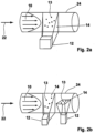
- Figure 3 represents a special variant of a flow measuring device 1, and the pipe section 24 is shown in a front view for illustration purposes and has the fluid 10 flowing through it. Particles 13 are located in the fluid 10, with one particle 13 being shown as an example.
- the wall of the pipe section 24 is designed to be transparent, for example, in order to radiate light by means of the light sources 11.
- the arrangement has a first light source 11 and a second light source 11 arranged within the pipe section 24 offset by 90° around its longitudinal axis. Both light sources 11 thus radiate light into the fluid 10 perpendicular to one another, resulting in two measuring planes 14 whose measuring planes are arranged perpendicular to one another.
- the Sensor unit 12 In the bisector between the extension planes of the two measuring planes 14, the Sensor unit 12, so that the observation directions 23 each enclose an angle of 135° to both light propagation directions of the light sources 11. If the flow measuring device 1 is operated and the light sources 11 emit corresponding light, which is received by the sensor unit 12 as scattered light formed on the particle 13, measurements can be taken in two measuring planes 14 with one sensor unit 12.
- Figure 4 shows, by way of example, particles 13 moving in the flow direction 22.
- a light source (not shown in detail) is used to generate scattered light, which first passes through a cylindrical lens array line sensor arrangement 21, whereby the movement of the particles 13 can be detected with the line sensors of the line sensor arrangement.
- photodiodes 20 can be used, which are also shown in the Figure 4 are shown.
- the scattered light alternately reaches the photodiodes 20 shown through the cylindrical lens array, so that a movement of the particles 13 can also be detected.
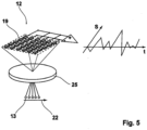
- Figure 5 shows a sensor unit 12, which is designed, for example, as a CMOS sensor 19. If the particles 13 shown as an example move below a lens 25, the individual pixels of the CMOS sensor 19 are illuminated one after the other by means of a light source (not shown) and scattered light generated on the particles 13, so that the backscattered light and the exposure of the CMOS sensor 19 cause a Signal S is generated over time t, which has a waveform. The more particles 13 there are in the fluid, the greater the amplitude of the signal S, whereby a speed of movement and a direction of movement of the particles 13 can be detected over time t.
- a light source not shown
- CMOS sensor 19 Due to the two-dimensionality of the CMOS sensor 19, a movement of the particles 13 in the fluid can occur both in the flow direction 22 and transversely Flow direction 22 can be detected, which is then done with the FPGA 15 (see Figure 1 ) can be reconstructed into a fully reconstructed digitally provided flow profile.
Description
Die Erfindung betrifft ein Strömungsmessverfahren zur optischen Messung von sich zeitlich ändernden Strömungsparametern eines durch einen geschlossenen Querschnitt strömenden Fluids und eine Strömungsmessvorrichtung hierzu, mit wenigstens einer Lichtquelle und mit wenigstens einer Sensoreinheit, mit der im Fluid vorhandene Partikel innerhalb einer Messebene erfasst werden.The invention relates to a flow measuring method for the optical measurement of time-changing flow parameters of a fluid flowing through a closed cross section and a flow measuring device for this purpose, with at least one light source and with at least one sensor unit, with which particles present in the fluid are detected within a measuring plane.
Viele Durchflussmessverfahren sind invasive Messverfahren, die die Strömung beeinflussen und damit beispielsweise eventuelle Messfehler induzieren. Daneben gibt es nicht-invasive Verfahren, die auf unterschiedlichen Wirkprinzipien beruhen.Many flow measurement methods are invasive measurement methods that influence the flow and thus, for example, induce possible measurement errors. There are also non-invasive procedures that are based on different principles of action.
Durch nicht-invasive Verfahren zur Strömungsmessung wird die Strömung des Fluids im Rohrabschnitt nicht gestört, wie dies durch den Einsatz von Messfühlern in der Strömung erfolgt, sodass nicht-invasive Messverfahren prinzipbedingt zu bevorzugen sind. Bei nicht-invasiven Verfahren zur Messung der Fließgeschwindigkeit eines Fluids erfolgt folglich keine mechanische Interaktion oder Kopplung mit dem Fluid, jedoch kann der Messaufwand deutlich größer sein als bei einer Strömungsmessung mittels einer mechanischen Wechselwirkung beispielsweise eines Messfühlers, der in das strömende Fluid hineinragt.Non-invasive methods for measuring flow do not disturb the flow of the fluid in the pipe section, as is the case with the use of sensors in the flow, so non-invasive measuring methods are preferable in principle. With non-invasive methods for measuring the flow rate of a fluid, there is therefore no mechanical interaction or coupling with the fluid, but the measurement effort can be significantly greater than with a flow measurement using mechanical interaction, for example a sensor that protrudes into the flowing fluid.
Derzeitig prozesstauglich einsetzbare nicht-invasive Durchfluss- und Volumenstrommessverfahren basieren auf unterschiedlichen Wirkprinzipien. Akustische Verfahren können ohne Modifikation des Rohres eingesetzt werden, liefern jedoch nur einen integralen Wert. Coriolis-Verfahren bestimmen den integralen Massenfluss. Magnetisch-induktive Verfahren setzen eine leitfähige Flüssigkeit voraus. Ein prozesstaugliches optisches Sensorprinzip zur Bestimmung des Durchflusses oder des Volumenstroms ist derzeit nicht realisiert und auch in der Literatur nicht bekannt. Durchfluss- und Volumenstrommessungen anhand eines Strömungsprofils in einem Rohr erfordern die kontinuierliche, zeitaufgelöste und echtzeitfähige Messung dieses Strömungsprofils. Die derzeit bekannten optischen Strömungsmesstechniken zur Bestimmung des Volumenstroms können nicht in Echtzeit kontinuierlich zeitaufgelöst mit vergleichsweise geringem Hardwareaufwand das Strömungsprofil in einem Rohrabschnitt bestimmen.Non-invasive flow and volume flow measurement methods that can currently be used in processes are based on different operating principles. Acoustic methods can be used without modifying the pipe, but only provide an integral value. Coriolis methods determine the integral mass flow. Magnetic-inductive methods require a conductive liquid. A process-compatible optical sensor principle for determining the flow or volume flow has not yet been implemented and is also not known in the literature. Flow and volume flow measurements based on a flow profile in a pipe require the continuous, time-resolved and real-time measurement of this flow profile. The currently known optical flow measurement techniques for determining the volume flow cannot determine the flow profile in a pipe section in real time, continuously with time resolution and with comparatively little hardware effort.
Optische Verfahren zur Strömungsmessung beispielsweise auch innerhalb eines Rohrabschnittes basieren auf der Einstrahlung von elektromagnetischen Wellen, insbesondere Licht, in das Fluid, beispielsweise wenn dieses durch den Rohrabschnitt fließt. Grundsätzlich lassen sich punktuelle Messverfahren, integrale Messverfahren und ortsauflösende Messverfahren unterscheiden.Optical methods for measuring flow, for example within a pipe section, are based on the radiation of electromagnetic waves, in particular light, into the fluid, for example when it flows through the pipe section. Basically, a distinction can be made between point-based measuring methods, integral measuring methods and spatially resolving measuring methods.
Ein Beispiel für ein punktuelles Messverfahren ist die Laser-Doppler-Technik. Hierbei kann immer nur ein lokal sehr eingeschränkter Bereich vermessen werden, und durch den kleinen sich ergebenden Messbereich kann nur eine ungenaue Angabe über den gesamten Volumenstrom des Fluids getroffen werden. Insbesondere betrifft dies Strömungen mit ausgeprägten oder sogar dynamisch veränderlichen Strömungsprofilen. Volumenstrommessungen mit der Laser-Doppler-Technik erfolgen typischerweise für stationäre Strömungen durch ein Abrastern des Profils.An example of a point measurement method is the laser Doppler technique. Only a locally very limited area can be measured, and due to the small resulting measuring range, only an imprecise indication of the total volume flow of the fluid can be made. This particularly applies to flows with pronounced or even dynamically changing flow profiles. Volume flow measurements using laser Doppler technology are typically carried out for stationary flows by scanning the profile.
Die Laser-Doppler Technik wurde in der
Ein integrales Verfahren ist der optische Laufzeit- oder Korrelations-Durchflussmesser, der z.B. aus der
Ein bekanntes optisches Messverfahren zur Bestimmung der ortsaufgelösten Strömungsgeschwindigkeit eines Fluides ist die sogenannte Particle Image Velocimetery. Diese bestimmt den lokalen zweidimensionalen Versatz von in der Strömung vorhandenen und abgebildeten Partikeln. Die Versatzschätzung basiert entweder auf der Kreuzkorrelation (Particle Image Velocimetry, kurz PIV) oder einem Tracking von Bildmerkmalen (Particle Tracking Velocimetry, kurz PTV). Aufgrund der sehr großen notwendigen Rechenleistung für die Auswertung der Bilddaten und die Bestimmung der lokalen Geschwindigkeitsvektoren ist eine kontinuierliche Echtzeitmessung der Strömungsgeschwindigkeit eines Fluids nicht ohne weiteres möglich. Die hierzu notwendige Messtechnik, insbesondere die Hardware für die Bereitstellung einer großen Rechenleistung, ist sehr kostenintensiv.A well-known optical measuring method for determining the spatially resolved flow velocity of a fluid is so-called particle image velocimetry. This determines the local two-dimensional offset of particles present and imaged in the flow. The offset estimate is based either on cross-correlation (particle image velocimetry, PIV for short) or on tracking of image features (particle tracking velocimetry, PTV for short). Due to the very high computing power required for evaluating the image data and determining the local velocity vectors, continuous real-time measurement of the flow velocity of a fluid is not easily possible. The measuring technology required for this, in particular the hardware for providing high computing power, is very cost-intensive.
Weiterhin erfordert die Particle Image Velocimetry eine gleichmäßige Fokussierung der Abbildung. Für Volumenstrommessungen in beispielweise runden Rohren und/oder für schräge Beobachtungsrichtungen ist eine hinreichende Homogenität der Fokussierung nicht gegeben und die Abbildungsqualität ändert sich lokal. Für eine homogene Abbildungsqualität bei schrägen Beobachtungsrichtungen nutzt die Particle Image Velocimety sogenannte Scheimflug-Anordnungen. Diese sind opto-mechanisch im Aufbau eher aufwendig und aufgrund von Mikrolinsenarrays nicht für alle Bildsensoren geeignet. Weiterhin erfordert die Particle Image Velocimetry eine Bildkalibrierung. Kontinuierliche zeitaufgelöste Echtzeit-Volumenstrommessungen mittels der Particle Image Velocimetry sind weder in der wissenschaftlichen Literatur noch im kommerziellen Bereich bekannt.Furthermore, particle image velocimetry requires uniform focusing of the image. For volume flow measurements in, for example, round pipes and/or for oblique observation directions, sufficient homogeneity of the focusing is not given and the image quality changes locally. For homogeneous image quality in oblique observation directions, particle image velocimetry uses so-called Scheimflug arrangements. These are rather complex in terms of opto-mechanical construction and are not suitable for all image sensors due to microlens arrays. Furthermore, particle image velocimetry requires image calibration. Continuous time-resolved real-time volume flow measurements using particle image velocimetry are neither known in the scientific literature nor in the commercial sector.
Ein weiteres optisches Verfahren zur Bestimmung von Bewegungen ist die abbildende Ortsfiltertechnik. Typischerweise wird die Ortsfiltertechnik als punktuelle Technik für die 1-komponentige punktuelle Geschwindigkeitsbestimmung von Oberflächen realisiert. Das Ortsfiltersignal ergibt sich aus der Überlagerung sehr vieler einzelner Streusignale.Another optical method for determining movements is the imaging spatial filter technique. Typically, the spatial filter technique is implemented as a point technique for the 1-component point velocity determination of surfaces. The spatial filter signal results from the superposition of many individual scattered signals.
Einige wissenschaftliche Arbeiten beschäftigen sich mit dem Einsatz der Ortsfiltertechnik zur Bestimmung von ortsaufgelösten Strömungsgeschwindigkeiten. Beispielsweise wird die Ortsfiltertechnik in
Die Ortsfiltertechnik wird auch zur Geschwindigkeitsbestimmung in Kapillaren eingesetzt. In der
Auch wird die Ortsfiltertechnik in
Aufgrund der volumetrischen Beleuchtung und der damit eingeschlossenen Tiefenintegration ist für eine quantitative Durchflussbestimmung eine Modellannahme für das Strömungsprofil notwendig. In Bergeler und Krambeer (2004) sowie in Menn (2010) wurden dementsprechend nur qualitative Aussagen über die gemessene Form des Strömungsprofils und ein quantitative Skalierung zum theoretischen Verlauf getroffen. Insgesamt ist ein solches Verfahren nicht echtzeitfähig und besitzt keine ausreichende Zeitauflösung und ist ferner auf bekannte Strömungsprofile beschränkt. Weiterhin erfordert das Verfahren sehr hohe Streupartikelkonzentrationen und große Streulichtpartikel und kann keine lokalen Querkomponenten in der Strömung erfassen, die beispielsweise bei Verwirbelungen oder beispielsweise bei einem Drall des Fluids in einem Strömungsquerschnitt entstehen.Due to the volumetric illumination and the depth integration involved, a model assumption for the flow profile is necessary for a quantitative flow determination. Accordingly, in Bergeler and Krambeer (2004) and in Menn (2010), only qualitative statements were made about the measured shape of the flow profile and a quantitative scaling to the theoretical course. Overall, such a method is not real-time capable and does not have sufficient time resolution and is also limited to known flow profiles. Furthermore, the method requires very high scattered particle concentrations and large scattered light particles and cannot determine local cross components in of the flow, which arise, for example, from turbulence or a swirl of the fluid in a flow cross-section.
Aufgabe der Erfindung ist die weitere Verbesserung einer Strömungsmessvorrichtung zur Messung des Volumenstroms und der Fließgeschwindigkeit eines innerhalb eines durch ein geschlossenen Querschnitt strömenden Fluids durch eine kontinuierliche zeitaufgelöste Identifikation des Strömungsprofils und die Schaffung eines entsprechenden Verfahrens hierzu, wobei die Strömungsmessvorrichtung ein optisches Messverfahren nutzen soll und Ausgangssignale der Strömungsmessung sollen in Echtzeit ausgegeben werden können.The object of the invention is to further improve a flow measuring device for measuring the volume flow and the flow velocity of a fluid flowing through a closed cross-section by a continuous time-resolved identification of the flow profile and to create a corresponding method for this, wherein the flow measuring device should use an optical measuring method and output signals of the flow measurement should be able to be output in real time.
Diese Aufgabe wird ausgehend von einem Strömungsmessverfahren gemäß dem Oberbegriff des Anspruches 1 und ausgehend von einem Verfahren gemäß dem Oberbegriff des Anspruches 10 mit den jeweils kennzeichnenden Merkmalen gelöst. Vorteilhafte Weiterbildungen der Erfindung sind in den abhängigen Ansprüchen angegeben.This object is achieved on the basis of a flow measurement method according to the preamble of claim 1 and on the basis of a method according to the preamble of
Die Erfindung schließt die technische Lehre ein, dass mit der Lichtquelle wenigstens eine Messebene und die darin vorhandenen Partikel beleuchtet werden, wobei die Partikel auf der Sensoreinheit abgebildet werden und die Sensoreinheit ein CMOS-Array-Detektor mit einem direkt verbundenen FPGA aufweist und wobei die Sensoreinheit mit wenigstens zwei oder mit einer Vielzahl von Einzeldetektoren bereitgestellt wird, mit der Sensorsignale betreffend Bildpunkte und/oder Bildlinien ausgegeben werden, und dass die Sensorsignale betreffend Bildpunkte und/oder Bildlinien unter Entfall einer Zwischenspeicherung mittels der Sensoreinheit kontinuierlich und in Echtzeit mittels Ortsfiltertechnik in wenigstens ein Geschwindigkeitsprofil umgerechnet werden, die Sensoreinheit aus dem zeitlich abhängigen Geschwindigkeitsprofil kontinuierlich und in Echtzeit Strömungsparameter, umfassend wenigstens zwei der folgenden Parameter: Volumenstrom, kumulierte Durchflussment Strömungsprofil, turbulenter/laminarer Strömungszustand, Turbulenzgrad, Turbulenzspektrum, Drall, die Sensoreinheit einen oder mehrere integrale Strömungszustandsparameter kontinuierlich, zeitaufgelöst und in Echtzeit berechnet und ausgibt, wobei der Sensoreinheit eine Recheneinheit nachgeschaltet wird, mit der die Geschwindigkeitsprofile auf der Grundlage der Integration und der Gewichtung der Bildpunkte und/oder Bildlinien durch das FPGA als integrale Strömungsparameter von der Recheneinheit verarbeitet werden und als Ausgangsignal von einem Ausgabemodul ausgegeben werden.The invention includes the technical teaching that at least one measuring plane and the particles present therein are illuminated with the light source, the particles being imaged on the sensor unit and the sensor unit having a CMOS array detector with a directly connected FPGA and the sensor unit being provided with at least two or with a plurality of individual detectors, with which sensor signals relating to pixels and/or image lines are output, and that the sensor signals relating to pixels and/or image lines are converted into at least one speed profile continuously and in real time by means of spatial filtering technology using the sensor unit, without intermediate storage, the sensor unit continuously and in real time calculates the speed profile from the time-dependent speed profile. Real-time flow parameters, comprising at least two of the following parameters: volume flow, cumulative flow profile, turbulent/laminar flow state, degree of turbulence, turbulence spectrum, swirl, the sensor unit calculates and outputs one or more integral flow state parameters continuously, time-resolved and in real time, wherein the sensor unit is followed by a computing unit with which the velocity profiles are processed by the computing unit as integral flow parameters on the basis of the integration and weighting of the image points and/or image lines by the FPGA and are output as an output signal by an output module.
Kerngedanke der Erfindung ist der Betrieb von zwei oder von mehreren Einzeldetektoren, die die Sensoreinheit bilden, und es können mit der einer nachgeschalteten Rechnereinheit in Echtzeit, also mit definierter zeitlicher Verzögerung, kontinuierlich bereitgestellt werden können.The core idea of the invention is the operation of two or more individual detectors that form the sensor unit, and the a downstream computer unit in real time, i.e. with a defined time delay, can be provided continuously.
Der wesentliche Vorteil liegt in der Kopplung von wenigstens einer Sensoreinheit zur optischen Strömungsmessung mit einem FPGA als Sensor zwischen der Sensoreinheit und einer nachgeschalteten Rechnereinheit. Dadurch wird eine Echtzeitfähigkeit der Bereitstellung des Ausgangssignal der Strömungsmessvorrichtung erreicht und es kann ein entsprechendes Verfahren ausgeführt werden, mit dem unter Nutzung der Strömungsmessvorrichtung mit einfachen Mitteln aufgrund des Einsatzes eines FPGA's zwischen der Sensoreinheit und der Rechnereinheit eine Echtzeit-Ausgabe von Ausgangssignalen der Vorrichtung möglich ist.The main advantage lies in the coupling of at least one sensor unit for optical flow measurement with an FPGA as a sensor between the sensor unit and a downstream computer unit. This achieves real-time capability for the provision of the output signal of the flow measuring device and a corresponding method can be carried out with which a real-time output of output signals from the device is possible using the flow measuring device with simple means due to the use of an FPGA between the sensor unit and the computer unit.
Bei geringen Partikelkonzentrationen bzw. bei sehr kleinen Partikeln in wenig verunreinigten Fluiden, z.B. Leitungswasser, ist die Streulichtleistung sehr gering. Erfindungsgemäß wird daher die Detektoreinheit unter Streulichtbereichen positioniert die eine höhere Streulichtleistung aufweisen, vorzugsweise Vorwärtsstreuung, Rückwärtsstreuung oder andere Streuwinkelpositionen.With low particle concentrations or with very small particles in slightly contaminated fluids, e.g. tap water, the scattered light output is very low. According to the invention, the detector unit is therefore positioned under scattered light areas which have a higher scattered light output, preferably forward scattering, backward scattering or other scattering angle positions.
Weiterer Vorteil dieser nichtsenkrechten Beobachtung der Messebene ist, dass das Detektor-Array den gesamten Strömungsquerschnitt in der Messebene auch bei gekrümmten, speziell auch kreisförmigen Rohrquerschnitten, erfasst. Mittels gewichteter Integration über das gesamte Strömungsprofil sind auch Volumenströme von Strömungen mit unsymmetrischen und/oder nicht voll ausgebildeten Strömungsprofilen möglich.Another advantage of this non-vertical observation of the measuring plane is that the detector array records the entire flow cross section in the measuring plane, even with curved, especially circular pipe cross sections. By means of weighted integration over the entire flow profile, volume flows of flows with asymmetrical and/or not fully developed flow profiles are also possible.
Insbesondere ergibt sich die Möglichkeit, einen FPGA an mehrere Sensoren zu koppeln, sodass nicht nur eine, sondern auch mehrere Messebenen ausgewertet werden können, um eine sehr genaue Erfassung der Fließgeschwindigkeit eines Fluids beispielsweise in einem Rohrabschnitt zu bestimmen, in dem das Fluid keine stationäre Strömung in Strömungsrichtung aufweist. Insbesondere ist erfindungsgemäß vorgesehen, dass das FPGA eine Programmkonfiguration aufweist, mit der von den Sensoreinheiten erfasste Bildpunkte und/oder Bildlinien basierend auf den bewegten Partikeln ein oder mehrere Bewegungsvektoren des Fluids erzeugt werden. Insbesondere kann die Programmkonfiguration dazu ausgebildet sein, mehrdimensionale Bewegungen der Partikel umzurechnen und als eindimensionales Ausgangssignal mittels des FPGA auszugeben. Mit der Verwendung nur eines FPGA's insbesondere in Verbindung mit mehreren Sensoren können Fluidbewegungen in Strömungsrichtung und quer zur Strömungsrichtung erfasst und ausgewertet werden, beispielsweise wenn Turbulenzen oder ein Drall in der Strömung des Fluids vorhanden sind.In particular, there is the possibility of coupling an FPGA to several sensors, so that not only one but also several measurement levels can be evaluated in order to achieve very precise detection to determine the flow velocity of a fluid, for example in a pipe section in which the fluid does not have a stationary flow in the flow direction. In particular, it is provided according to the invention that the FPGA has a program configuration with which one or more motion vectors of the fluid are generated based on the moving particles and image points and/or image lines detected by the sensor units. In particular, the program configuration can be designed to convert multi-dimensional movements of the particles and output them as a one-dimensional output signal using the FPGA. By using only one FPGA, especially in conjunction with several sensors, fluid movements in the direction of flow and transverse to the direction of flow can be recorded and evaluated, for example if turbulence or a swirl is present in the flow of the fluid.
Der Rechnereinheit ist ein Ausgabemodul nachgeschaltet, an das die Bewegungsvektoren des Fluids von der Rechnereinheit ausgebbar sind und durch das basierend auf den Bewegungsvektoren eine Strömungsgeschwindigkeit des Fluids als Ausgangssignal angegeben werden kann.An output module is connected downstream of the computer unit, to which the motion vectors of the fluid can be output from the computer unit and through which a flow velocity of the fluid can be specified as an output signal based on the motion vectors.
Im Rahmen der Erfindung ist es insbesondere vorgesehen, dass die Sensoreinheit wenigstens einen CMOS-Sensor aufweist, alternativ besteht auch die Möglichkeit, dass die Sensoreinheit eine Anordnung von Photodioden und/oder wenigstens eine Zylinderlinsenarray-Zeilensensoranordnung aufweist, wobei auch wenigstens ein CCD-Sensor zur Bildung der Sensoreinheit vorgesehen sein kann. Auf den CMOS-Sensor kann mit einer entsprechenden Optik die flächige Messebene abgebildet werden, sodass Bewegungen der Partikel in einer ersten Richtung und in einer senkrecht dazu ausgebildeten zweiten Richtung erfasst werden können. Die Erfassung erfolgt dabei insbesondere auf Basis der Ortsfiltertechnik, wobei Bewegungen des Fluids quer zur Strömungsrichtung erfasst und mittels des FPGA auf die Geschwindigkeitskomponente in Strömungsrichtung umgerechnet werden können.Within the scope of the invention, it is particularly provided that the sensor unit has at least one CMOS sensor; alternatively, it is also possible for the sensor unit to have an arrangement of photodiodes and/or at least one cylindrical lens array line sensor arrangement, whereby at least one CCD sensor can also be provided to form the sensor unit. The flat measurement plane can be imaged onto the CMOS sensor using appropriate optics, so that movements of the particles in a first direction and in a second direction perpendicular to it can be recorded. The recording takes place in particular on the basis of the spatial filter technique, whereby movements of the fluid perpendicular to the flow direction can be recorded and converted to the velocity component in the flow direction using the FPGA.
Die Messebene ist innerhalb des Strömungsvolumens gebildet, wobei einer ersten Messebene eine erste Sensoreinheit und einer zweiten Messebene eine zweite Sensoreinheit zugeordnet ist, wobei die Messebenen in Strömungsrichtung des Fluids hintereinander folgend angeordnet sind, wobei eine Anordnung hintereinander nicht zwingend notwendig, aber vorteilhaft ist. Durch die Anordnung mehrerer Messebenen kann die Genauigkeit der Strömungsmessung weiter verbessert werden, und insbesondere können die Messebenen unter einem bekannten Winkelversatz zueinander angeordnet sein, beispielsweise 60° bis 180° und bevorzugt 90°. Auch ist es von Vorteil, wenn die Messebenen zur Normalen der Sensoreinheiten einen Winkel zwischen 20° bis 50° und insbesondere von 30° aufweisen. Ebenfalls kann es vorteilhaft sein, wenn der Winkel der Messebenen zur Normalen der zugeordneten Sensoreinheit 45° beträgt.The measuring plane is formed within the flow volume, with a first measuring plane being assigned to a first sensor unit and a second measuring plane being assigned to a second sensor unit, with the measuring planes being arranged one after the other in the flow direction of the fluid, with an arrangement one after the other not absolutely necessary but advantageous. By arranging several measuring planes, the accuracy of the flow measurement can be further improved and in particular the measuring planes can be arranged at a known angular offset from one another, for example 60° to 180° and preferably 90°. It is also advantageous if the measuring planes have an angle of between 20° and 50° and in particular 30° to the normal of the sensor units. It can also be advantageous if the angle of the measuring planes to the normal of the assigned sensor unit is 45°.
Mit besonderem Vorteil ist die Beobachtungsrichtung der Sensoreinheit damit unter einem Winkelversatz entgegen der Emissionsrichtung eines Lichtes einer Lichtquelle eingerichtet, wobei der Winkelversatz wie vorstehen beschreiben beispielsweise 20° bis 50° und insbesondere 30° in Vorwärts- oder Rückwärtsstreuung beträgt. Dadurch kann eine besonders hohe Streulichtintensität ausgenutzt werden, wodurch die Messgenauigkeit weiter verbessert wird.It is particularly advantageous if the observation direction of the sensor unit is set up at an angular offset opposite to the emission direction of a light source, the angular offset being, as described above, for example 20° to 50° and in particular 30° in forward or backward scattering. This allows a particularly high scattered light intensity to be utilized, which further improves the measurement accuracy.
Ein noch weiterer Vorteil wird erreicht, wenn mehrere Lichtquellen so zueinander und zu der Sensoreinheit angeordnet sind, dass mehrere Messebenen von einer Sensoreinheit erfassbar sind. Beispielsweise können zwei Messebenen ausgebildet sein, die senkrecht zueinander stehen. Insbesondere können wenigstens zwei Lichtquellen so zueinander und zu der Sensoreinheit angeordnet werden, dass wenigstens zwei mit einer gemeinsamen Schnittlinie oder in Strömungsrichtung hintereinander liegende Messebenen geschaffen und von nur einer Sensoreinheit erfasst werden.A further advantage is achieved when several light sources are arranged in relation to each other and to the sensor unit in such a way that several measurement planes can be detected by one sensor unit. For example, Two measuring planes can be formed that are perpendicular to each other. In particular, at least two light sources can be arranged in relation to each other and to the sensor unit in such a way that at least two measuring planes are created that are located one behind the other with a common intersection line or in the direction of flow and are detected by only one sensor unit.
Die eine Sensoreinheit befindet sich beispielsweise in diametral gegenüberliegender Anordnung zu den beiden Messebenen, die durch die entsprechende Anordnung der Lichtquellen erzeugt werden, sodass ebenfalls als Gegenlicht das Streulicht mit einer Beobachtungsrichtung erfasst wird, die in der Winkelhalbierenden zwischen den beiden Lichtquellen liegt. Die Lichtquellen können dabei beispielsweise Licht mit unterschiedlichen Wellenlängen aussenden oder die Lichtquellen werden gepulst betrieben, und die Lichtpulse werden beispielsweise abwechselnd von den Lichtquellen erzeugt. Damit kann mittels der einen Sensoreinheit, insbesondere ausgebildet als CMOS-Sensor, sowohl eine erste Messebene als auch eine zweite Messebene erfasst werden.One sensor unit is located, for example, in a diametrically opposite arrangement to the two measuring planes, which are generated by the corresponding arrangement of the light sources, so that the scattered light is also detected as backlight with an observation direction that lies in the bisector of the angle between the two light sources. The light sources can, for example, emit light with different wavelengths or the light sources are operated in a pulsed manner, and the light pulses are, for example, generated alternately by the light sources. This means that both a first measurement level and a second measurement level can be detected by means of the one sensor unit, in particular designed as a CMOS sensor.
Insbesondere können zwei Messebenen auch so ausgebildet sein, dass sie auf unterschiedlichen Bereichen des Sensors abgebildet werden. Beispielsweise können zwei oder mehr parallele Messebenen mit einem Sensor abgebildet werden, sodass sich die Abbildungen nicht überlappen.In particular, two measurement planes can also be designed so that they are imaged on different areas of the sensor. For example, two or more parallel measurement planes can be imaged with one sensor so that the images do not overlap.
Die Erfindung richtet sich weiterhin auf ein Verfahren zur Strömungsmessung des Fluids mittels der vorstehend beschriebenen Strömungsmessvorrichtung.The invention further relates to a method for measuring the flow of the fluid by means of the flow measuring device described above.
Insbesondere richtet sich die Erfindung weiterhin auf eine Strömungsmessvorrichtung, die einen Rohrabschnitt aufweist, der mit einem Fluid durchströmbar ist, und die zumindest eine Lichtquelle aufweist, mit der Licht in den Rohrabschnitt einstrahlbar ist und mit der in wenigstens einer Messebene die im Fluid vorhandenen Partikel beleuchtbar sind, wobei wenigstens eine Sensoreinheit vorgesehen ist, mit der im Fluid vorhandene Partikel innerhalb einer Messebene erfassbar sind, und wobei die Sensoreinheit wenigstens zwei oder eine Vielzahl von Einzeldetektoren aufweist, mit der Sensorsignale ausgebbar sind, und wobei der Sensoreinheit eine Recheneinheit nachgeschaltet ist, mit der die Sensorsignale mit einer Integration und Wichtung der Einzelsignale der Einzeldetektoren unter Anwendung der Ortsfiltertechnik in Echtzeit verarbeitbar und als Ausgangssignal ausgebbar sind.In particular, the invention further relates to a flow measuring device which has a pipe section through which a fluid can flow and which has at least one light source, with which light can be radiated into the pipe section and with which the particles present in the fluid can be illuminated in at least one measuring plane, wherein at least one sensor unit is provided with which particles present in the fluid can be detected within a measuring plane, and wherein the sensor unit has at least two or a plurality of individual detectors with which sensor signals can be output, and wherein the sensor unit is followed by a computing unit with which the sensor signals can be processed in real time with an integration and weighting of the individual signals of the individual detectors using the spatial filter technique and can be output as an output signal.
Weiterhin ist gemäß einer vorteilhaften Ausführungsform ein Feld-programmierbares-Gatter-Array in Anordnung zwischen der Sensoreinheit und der Recheneinheit vorgesehen, das mit einer Programmkonfiguration betreibbar ist, mit der von der Sensoreinheit erfasste Bildpunkte und/oder Bildlinien basierend auf den bewegten Partikeln Bewegungsvektoren des Fluids erzeugbar sind.Furthermore, according to an advantageous embodiment, a field-programmable gate array is provided in an arrangement between the sensor unit and the computing unit, which can be operated with a program configuration with which image points and/or image lines detected by the sensor unit are motion vectors of the fluid based on the moving particles can be generated.
Zusätzlich ist es von Vorteil, dass bei einer Aufbereitung der Daten des oder der Sensoreinheiten mittels des FPGA's mehrdimensionale Bewegungen der Partikel entlang und quer zu einer Strömungsrichtung zu einer Strömungsgeschwindigkeit des Fluids umgerechnet und ausgegeben werden. Insbesondere ist vorgesehen, dass die wenigstens eine Lichtquelle kontinuierliches oder gepulstes Licht ausgibt und/oder es ist vorgesehen, dass die wenigstens eine Lichtquelle Licht mit voneinander unterschiedlichen Wellenlängen ausgibt.In addition, it is advantageous that when the data from the sensor unit(s) is processed using the FPGA, multi-dimensional movements of the particles along and across a flow direction are converted into a flow velocity of the fluid and output. In particular, it is provided that the at least one light source outputs continuous or pulsed light and/or it is provided that the at least one light source outputs light with different wavelengths from one another.
Mit der erfindungsgemäßen Strömungsmessvorrichtung und insbesondere mit dem erfindungsgemäßen Verfahren kann die Strömungsgeschwindigkeit eines Fluids ermittelt werden, beispielsweise bei einem Durchfluss durch einen Rohrabschnitt oder durch einen Kanal mit einem geschlossenen Querschnitt, und es kann die Ortsfiltertechnik Verwendung finden. Der Vorteil sind die Erfassung lokaler Geschwindigkeitsvektoren innerhalb der Strömung des Fluids, damit mittels des FPGA und der nachgeschalteten Rechnereinheit nicht nur eine eindimensionale Strömung ermittelt, sondern ein oder mehrere Strömungsprofile in Querschnittsrichtung rekonstruiert werden kann. Die allermeisten Fluide weisen hinreichend viele Partikel auf, die mit der Strömung im Fluid mitbewegt werden, sodass eine optische Strömungsmessung ausgeführt werden kann.With the flow measuring device according to the invention and in particular with the method according to the invention, the flow velocity of a fluid can be determined, for example when flowing through a pipe section or through a channel with a closed cross-section, and the spatial filter technique can be used. The advantage is the detection of local velocity vectors within the flow of the fluid, so that not only a one-dimensional flow can be determined using the FPGA and the downstream computer unit, but one or more flow profiles can be reconstructed in the cross-sectional direction. The vast majority of fluids have a sufficient number of particles that move with the flow in the fluid, so that an optical flow measurement can be carried out.
Realisiert wird dies insbesondere durch die Bildung mehrerer Messebenen, insbesondere mehrerer Messebene innerhalb des Strömungsvolumens, die zueinander einen Winkel einschließen oder versetzt zueinander liegen. Insbesondere durch die Zweidimensionalität der Sensoreinheit, der vorzugsweise als CMOS- Sensor ausgebildet ist, können mehrere Lichtschnitte gebildet werden, und die Sensoreinheiten können diskreten Lichtquellen zugeordnet sein, die verschiedene Wellenlängen oder verschiedene Pulsfolgen aufweisen oder diese aussenden oder auf unterschiedlichen Bereichen des Sensors abgebildet werden. Insbesondere können die Lichtquellen farblich unterschiedliches Licht oder zeitlich versetzte Pulse aussenden, die mit den Sensoreinheiten entsprechend erfasst werden. Damit können räumlich voneinander getrennt angeordnete Messebenen auch mit nur einer Sensoreinheit erfasst werden. Im Ergebnis ergibt sich die Möglichkeit der Echtzeiterfassung und Identifikation unsymmetrischer Strömungsprofile innerhalb eines Strömungsquerschnitts, beispielsweise innerhalb eines Rohrabschnitts. Auch eignet sich ein solches Verfahren basierend auf der Ortsfiltertechnik dazu, Fluide mit sehr geringer Partikeldichte messen zu können.This is achieved in particular by forming several measuring planes, in particular several measuring planes within the flow volume, which form an angle with one another or are offset from one another. In particular, the two-dimensionality of the sensor unit, which is preferably designed as a CMOS sensor, allows several light sections to be formed, and the sensor units can be assigned to discrete light sources that have different wavelengths or different pulse sequences or emit these or are imaged on different areas of the sensor. In particular, the light sources can emit light of different colors or temporally offset pulses, which are recorded accordingly by the sensor units. This means that measuring planes that are spatially separated from one another can also be recorded with just one sensor unit. The result is the possibility of real-time recording and identification of asymmetrical flow profiles within a flow cross-section, for example within a pipe section. Such a method based on spatial filter technology is also suitable for measuring fluids with a very low particle density.
Insbesondere ergibt sich der Vorteil, dass durch den Einsatz der optischen Ortsfiltertechnik die Beobachtungsrichtung im Verhältnis zur Lichteinkopplungsrichtung so gewählt werden kann, dass eine optimale Intensität der Partikelabbildung durch die bessere Streulichtleistung erreicht wird, ohne dass ein optisches Prisma oder ein Scheimpflugadapter oder eine Brechungsindexanpassung zwangsweise eingesetzt werden muss, insbesondere bei einer Vorwärts- oder Rückwärtsstreuung mit einem Winkelversatz von etwa 20° bis 50°. Insbesondere durch die Einstellung eines 30°-Winkels ist es möglich, mehrere Messebenen aus verschiedenen Winkeln durch nur eine Sensoreinheit zu erfassen, wodurch eine kostengünstige Realisierung der Strömungsmessvorrichtung mit zwei Lichtquellen und nur einer Sensoreinheit ermöglicht wird.In particular, the advantage is that the use of optical spatial filter technology allows the observation direction to be adjusted in relation to the The light coupling direction can be selected so that an optimal intensity of the particle image is achieved through the better scattered light performance, without the compulsory use of an optical prism or a Scheimpflug adapter or a refractive index adjustment, especially in the case of forward or backward scattering with an angular offset of approximately 20° to 50°. In particular, by setting a 30° angle, it is possible to capture several measuring planes from different angles using just one sensor unit, which enables a cost-effective implementation of the flow measuring device with two light sources and just one sensor unit.
Wird gepulstes Licht verwendet, insbesondere anstatt einer Dauerbeleuchtung, können höhere Lichtleistungen der Lichtquelle oder der Lichtquellen realisiert werden, und es entsteht eine geringere Bewegungsunschärfe. Auch sind mehrere Ebenen zur Beobachtung realisierbar, und es entsteht ein besserer Signal-Rausch-Abstand in der Sensoreinheit durch die Reduktion von Streulicht und des thermischen Rauschens.If pulsed light is used, especially instead of continuous lighting, higher light outputs of the light source or light sources can be achieved and less motion blur occurs. Multiple levels of observation can also be implemented, and a better signal-to-noise ratio is created in the sensor unit by reducing scattered light and thermal noise.
Die erfindungsgemäße Strömungsmessvorrichtung ermöglicht insbesondere auch die Detektion des Verschmutzungsgrades beziehungsweise der Signalqualität bei einzelnen CMOS- Sensoren zur Bildung der Sensoreinheiten. Der Vorteil liegt insbesondere in der Detektion und damit der Reduktion eines Prozessdriftes, und es kann eine Verschmutzungserkennung im Fluid erfolgen, insbesondere können Wartungsmeldungen abgegeben werden, beispielsweise zur vorausschauenden Wartung eines fluidischen Systems.The flow measuring device according to the invention also enables, in particular, the detection of the degree of contamination or the signal quality in individual CMOS sensors to form the sensor units. The advantage lies in particular in the detection and thus the reduction of process drift, and contamination in the fluid can be detected; in particular, maintenance messages can be issued, for example for the predictive maintenance of a fluidic system.
Das Verfahren benötigt keine optische Kalibrierung, da bei geraden Rohrstücken im Bereich der Messebene keine Verzeichnung entlang der Hauptströmungsrichtung aufgrund von gekrümmten Oberflächen vorhanden ist. Bei typischerweise bekanntem Rohrquerschnitt und aufgrund der Abbildung des gesamten Rohrquerschnitts auf dem Detektor-Array kann der Abbildungsmaßstab einfach aus den Bilddaten ermittelt werden.The method does not require any optical calibration, since straight pipe sections in the area of the measuring plane have no distortion along the main flow direction due to curved surfaces is available. If the pipe cross section is typically known and the entire pipe cross section is imaged on the detector array, the imaging scale can be easily determined from the image data.
Die Messebene wird mit einer Optik auf das Detektor-Array abgebildet, wobei die Optik erfindungsgemäß keine zusätzlich Korrektur der Schärfe, z.B. typische Scheimflug-Konfiguration, oder Verzeichnung erzeugen muss. Bei Beobachtung unter einem schrägen Winkel können die Abbildungsparameter, wie z.B. Fokus, im Bild inhomogen sein. Aufgrund der Erfindung hat dies keinen Einfluss auf die Bestimmung des Strömungsprofils. Bei Bewegung des Fluids bewegen sich die mitgeführten und beleuchtetet Partikel mit dem Fluid entlang der Strömungslinien. Aufgrund der schrägen Beobachtung sind die bewegten Partikelabbildungen auf dem Detektor-Array unterschiedlich stark defokussiert. Das Detektor-Array kann dabei als Matrixsensor, z.B. flächiger CCD-, CMOS-, oder Smart-Pixel-Sensor, aber auch als Photodioden-Array realisiert werden.The measurement plane is imaged onto the detector array using optics, whereby the optics do not need to produce any additional correction of the sharpness, e.g. typical Scheimflug configuration, or distortion according to the invention. When observing at an oblique angle, the imaging parameters, such as focus, can be inhomogeneous in the image. Due to the invention, this has no influence on the determination of the flow profile. When the fluid moves, the entrained and illuminated particles move with the fluid along the flow lines. Due to the oblique observation, the moving particle images on the detector array are defocused to varying degrees. The detector array can be implemented as a matrix sensor, e.g. a flat CCD, CMOS or smart pixel sensor, but also as a photodiode array.
Erfindungsgemäß werden die Werte des Detektorarrays mit einer oder mehreren Wichtungsfunktionen multipliziert und über Teilbereiche des Detektor-Arrays, vorzugsweise entlang der Strömungslinien, integriert bzw. summiert. Dies ermöglicht trotz inhomogener Defokussierung die Bestimmung von geschwindigkeitsproportionalen Messwerten, welche repräsentativ für die ausgewählten Teilbereiche der Strömung sind.According to the invention, the values of the detector array are multiplied by one or more weighting functions and integrated or summed over partial areas of the detector array, preferably along the flow lines. Despite inhomogeneous defocusing, this enables the determination of velocity-proportional measured values which are representative of the selected sub-areas of the flow.
Vorteil dieses Verfahrens ist, dass für die Geschwindigkeitsbestimmung nur zwei Operationen pro Element des Array-Detektors, eine konstante Wichtung und eine Summation, notwendig sind. Erst dadurch wird, im Vergleich zu anderen Techniken (PIV) eine ausreichende zeitliche Auflösung und eine Echtzeitfähigkeit des Verfahrens möglich.The advantage of this method is that only two operations per element of the array detector are necessary to determine the speed: a constant weighting and a summation. This is the only way to achieve sufficient temporal resolution and real-time capability of the method compared to other techniques (PIV).
Diese Operationen, Wichtung und Integration/Summation, können zweckmäßigerweise optisch, elektronisch oder rechentechnisch erfolgen. Eine optische oder elektronische Wichtung und/oder Integration bedingen Hardwareänderungen oder spezielle Optiken und Sensoren, während die rechentechnische Wichtung und Summation mit einer nachgeschalteten echtzeitfähigen Auswertehardware bzw. Recheneinheit möglich wird.These operations, weighting and integration/summation, can be carried out optically, electronically or computationally. Optical or electronic weighting and/or integration require hardware changes or special optics and sensors, while computational weighting and summation is possible with downstream real-time capable evaluation hardware or computing unit.
Die rechentechnische Realisierung besitzt darüber hinaus den Vorteil, die ausgewählten Teilbereiche und die Wichtung dynamisch an den Prozess oder den momentanen Prozesszustand anzupassen. Zweckmäßigerweise würden die Teilbereiche in Hauptströmungsrichtung gelegt, so dass jeder Teilbereich einen lokalen Strömungsprofilmesswert erzeugt. Bei großem Dynamikbereich der Strömung, z.B. von laminar bis hoch-turbulent, bei zeitlich hochdynamischen Volumenstromänderungen, oder bei nicht vollständig ausgebildeten Strömungsprofilen können die Teilbereich und die Wichtungsfunktionen modifiziert, angepasst oder in der Anzahl verändert werden, um beispielsweise Querkomponenten im Strömungsprofil oder Rückströmungen zu erfassen. Vorteil ist, dass so die Dynamik der Volumenstrommessung mehrere Größenordnungen beträgt.The computational implementation also has the advantage of being able to dynamically adapt the selected sub-areas and the weighting to the process or the current process state. The sub-areas would be placed in the main flow direction so that each sub-area generates a local flow profile measurement value. If the flow has a large dynamic range, e.g. from laminar to highly turbulent, if the volume flow changes are highly dynamic over time, or if the flow profile is not fully developed, the sub-areas and the weighting functions can be modified, adapted or the number can be changed in order to capture, for example, transverse components in the flow profile or backflows. The advantage is that the dynamics of the volume flow measurement is several orders of magnitude.
Die Erfindung schließt eine spezialisierte Recheneinheit zur echtzeitfähigen und zeitaufgelösten Verarbeitung der Eingangsdaten der Array-Detektoren, insbesondere ein Field Programmable Gate Array (FPGA), ein. Die Recheneinheit empfängt die Daten des Array-Detektors und implementiert die Wichtungsfunktion oder Wichtungsfunktionen, die Summation über die Teilbereiche, die Umrechnung in Geschwindigkeitswerte sowie die Berechnung des Volumenstroms und des Durchflusses. Je nach Ausgestaltung des Verfahrens kann die Wichtung und/oder Summation optisch oder elektronisch vor und/oder die Geschwindigkeitsbestimmung und Volumenstromberechnung nach der Recheneinheit in einem separaten Controller erfolgen.The invention includes a specialized computing unit for real-time capable and time-resolved processing of the input data of the array detectors, in particular a field programmable gate array (FPGA). The computing unit receives the data from the array detector and implements the weighting function or functions, the summation over the sub-areas, the conversion into velocity values and the calculation of the volume flow and the flow rate. Depending on the design of the method, the weighting and/or summation can be carried out optically or electronically and/or the speed determination and volume flow calculation after the computing unit in a separate controller.
Weitere, die Erfindung verbessernde Maßnahmen werden nachstehend gemeinsam mit der Beschreibung bevorzugter Ausführungsbeispiele der Erfindung anhand der Figuren näher dargestellt. Es zeigt:
- Figur 1
- eine schematische Ansicht der Komponenten der Strömungsmessvorrichtung,
- Figur 2a
- eine schematische Ansicht eines Rohrabschnittes mit einer einzelnen Messebene und einem der Messebene zugeordneten Sensoreinheit,
- Figur 2b
- eine schematische Ansicht eines Rohrabschnittes mit einer ersten Messebene, mit einer zweiten Messebene und mit zwei den jeweiligen Messebenen zugeordneten Sensoreinheiten,
- Figur 3
- eine schematische Ansicht des Rohrabschnittes mit zwei Lichtquellen und eine Sensoreinheit zur Erkennung von Partikeln,
- Figur 4
- eine schematische Ansicht einer Zylinderlinsenarray-Zeilensensoranordnung sowie von zwei Photodioden und
- Figur 5
- eine schematische Ansicht einer Sensoreinheit, ausgebildet als CMOS- Sensor zur Beobachtung von Partikeln in einem Fluid.
- Figure 1
- a schematic view of the components of the flow measuring device,
- Figure 2a
- a schematic view of a pipe section with a single measuring plane and a sensor unit assigned to the measuring plane,
- Figure 2b
- a schematic view of a pipe section with a first measuring plane, with a second measuring plane and with two sensor units assigned to the respective measuring planes,
- Figure 3
- a schematic view of the pipe section with two light sources and a sensor unit for detecting particles,
- Figure 4
- a schematic view of a cylindrical lens array line sensor arrangement as well as two photodiodes and
- Figure 5
- a schematic view of a sensor unit, designed as a CMOS sensor for observing particles in a fluid.
Derartige Feld-programmierbare-Gatter-Arrays 15 werden allgemein auch als FPGA's 15 bezeichnet, und das dargestellte FPGA 15 liefert eine aufbereitete Information an eine Rechnereinheit 16. Die Rechnereinheit 16 ist dazu ausgebildet, Ausgangssignale an ein Ausgabemodul 17 bereitzustellen, das die Geschwindigkeitsinformation des Fluids schließlich als Ausgangssignal 18 ausgibt.Such field-
Die wenigstens eine Lichtquelle 11 ist beispielsweise als Laserlichtquelle ausgebildet, wobei für das vorliegende Messverfahren auch Leuchtdioden (LED's) zum Einsatz kommen können. Für die Ausführung der Ortsfiltertechnik mit der erfindungsgemäßen Strömungsmessvorrichtung 1 ist nicht grundsätzlich der Einsatz von kohärentem Licht erforderlich, sodass auch eine Leuchtdiode als Lichtquelle 11 dienen kann.The at least one
Die Lichtquelle 11 emittiert entweder kontinuierliches Licht oder gepulstes Licht, und es ist denkbar, dass die Lichtquelle 11 oder mehrere Lichtquellen 11 unterschiedliche Wellenlängen emittieren können.The
Die Messebenen 14 bilden Messebenen innerhalb des Strömungsvolumens, und jeder Messebene 14 ist eine Sensoreinheit 12 zugeordnet, wobei eine Sensoreinheit 12 auch mehrere Messebenen 14 sensieren kann. Innerhalb des Strömungsvolumens können insbesondere zwei Messebenen 14 vorgesehen sein, die in Strömungsrichtung des Fluids aufeinanderfolgend angeordnet sind und Lichtschnitte bilden, die zueinander gedreht sind, beispielsweise um 90°. Eine entsprechende Rotation weist dabei auch die Anordnung von zwei Sensoreinheiten 12 auf, die jedem der Messebenen 14 zugeordnet sind.The measuring planes 14 form measuring planes within the flow volume, and each measuring
Die Sensoreinheit 12 oder die Sensoreinheiten 12 werden insbesondere durch CMOS- Sensoren gebildet, wobei auch die Möglichkeit besteht, beispielsweise zwei Photodioden entsprechend anzuordnen, vorzugsweise in Verbindung mit einem optischen Gitter, das der Sensoreinheit 12 vorgelagert ist. Auch besteht die Möglichkeit, eine Zylinderlinsenarray-Zeilensensoranordnung zur Bildung von Sensoreinheiten 12 vorzusehen, wodurch die Strömungsmessvorrichtung 1 kostengünstig ausgeführt sein kann.The
Das nachfolgend auf der Sensoreinheit 12 gezeigte FPGA 15 weist eine Programmkonfiguration auf, mit der von der Sensoreinheit 12 erfasste Bildpunkte und/oder Bildlinien basierend auf den bewegten Partikeln innerhalb des Fluids Bewegungsvektoren der Partikel und damit des Fluids erzeugt werden können. Die Erzeugung der Bewegungsvektoren erfolgt dabei in Echtzeit, und die entsprechenden Informationen werden an eine nachgeschaltete Rechnereinheit 16 ausgegeben. Mit der Rechnereinheit 16 kann schließlich über ein Ausgabemodul 17 das Ausgangssignal 18 ausgegeben werden.The
Ein besonderer Vorteil des Einsatzes des FPGA 15 liegt darin, dass Bewegungen des Fluids quer zur Hauptströmungsrichtung des Fluids erfasst und auf eine 2D-Information umgerechnet werden können, sodass schließlich ein Vergleichswert geschaffen wird, mit dem über dem gesamten Strömungsquerschnitt ein entsprechender Geschwindigkeitsvektor gebildet wird, der sich als finale Vektorinformation ergibt, wobei die Strömung auch Rotationsanteile oder Verwirbelungen um die Längsachse der Strömungsrichtung aufweisen kann. Diese Umrechnung erfolgt dabei im FPGA 15 und kann als einfache Vektorinformation an die Rechnereinheit 16 ausgegeben werden.A particular advantage of using the
In dem Fluid 10 sind Partikel 13 vorhanden, die innerhalb der Messebenen 14 von der Sensoreinheit 12 erfasst werden. Die Erfassung der Bewegung der Partikel 13 erfolgt dabei sowohl in Strömungsrichtung 22 als auch quer zur Strömungsrichtung 22 innerhalb der Messebene 14.
Werden die Bewegungen der Partikel 13 in den Messebenen 14 erfasst, können auch Rotationen und Verwirbelungen, insbesondere ein Drall, in der Strömung des Fluids 10 erkannt werden, wobei die Informationen aus beiden Sensoreinheiten 12 dem FPGA 15 (siehe
Die Anordnung weist eine erste Lichtquelle 11 und eine innerhalb des Rohrabschnittes 24 um 90° um dessen Längsachse versetzt angeordnete zweite Lichtquelle 11 auf. Beide Lichtquellen 11 strahlen damit senkrecht zueinander Licht in das Fluid 10 ein, sodass sich zwei Messebenen 14 ergeben, deren Messebenen senkrecht aufeinander stehend ausgebildet sind. In der Winkelhalbierenden zwischen den Erstreckungsebenen der beiden Messebenen 14 befindet sich außerhalb des Rohrabschnittes 24 die Sensoreinheit 12, sodass die Beobachtungsrichtungen 23 zu beiden Lichtausbreitungsrichtungen der Lichtquellen 11 jeweils einen Winkel von 135° einschließen. Wird die Strömungsmessvorrichtung 1 betrieben, und emittieren die Lichtquellen 11 entsprechendes Licht, das mit der Sensoreinheit 12 als am Partikel 13 gebildetes Streulicht empfangen wird, so kann mit einer Sensoreinheit 12 in zwei Messebenen 14 gemessen werden.The arrangement has a
Die Erfindung beschränkt sich in ihrer Ausführung nicht auf das vorstehend angegebene, bevorzugte Ausführungsbeispiel. Vielmehr ist eine Anzahl von Varianten denkbar, welche von der dargestellten Lösung auch bei grundsätzlich anders gearteten Ausführungen Gebrauch macht.The implementation of the invention is not limited to the preferred exemplary embodiment specified above. Rather, a number of variants are conceivable, which make use of the solution presented even in fundamentally different designs.
- 11
- StrömungsmessvorrichtungFlow measuring device
- 1010
- FluidFluid
- 1111
- LichtquelleLight source
- 1212
- SensoreinheitSensor unit
- 1313
- PartikelParticles
- 1414
- MessebeneMeasuring level
- 1515
- Feld-programmierbares-Gatter-ArrayField-programmable gate array
- 1616
- RechnereinheitComputing unit
- 1717
- AusgabemodulOutput module
- 1818
- AusgangssignalOutput signal
- 1919
- CMOS- SensorCMOS sensor
- 2020
- Photodiodephotodiode
- 2121
- Zylinderlinsenarray - ZeilensensoranordnungCylindrical lens array - line sensor arrangement
- 2222
- StrömungsrichtungFlow direction
- 2323
- BeobachtungsrichtungDirection of observation
- 2424
- RohrabschnittPipe section
- 2525
- Objektivlens
- SS
- SensorsignalSensor signal
- tt
- ZeitTime
Claims (10)
- A flow measuring method for the optical measurement of time variable flow parameters of a fluid (10) flowing through a closed cross-section having at least one light source (11) and having at least one sensor unit (12) by which particles (13) present within a measurement plane (14) in the fluid (10) are detected, wherein- at least one measurement plane and the particles (13) present therein are illuminated by the light source (11); wherein- the particles are imaged on the sensor unit (12), and characterized in that- the sensor unit (12) has a CMOS array detector (19) having a directly connected FPGA (15) and with the sensor unit (12) being provided with at least two or with a plurality of individual detectors (12a, 12b, 12c, 12b) by which sensor signals (S) relating to picture elements and/or picture lines are output; and in that- the sensor signals (S) relating to picture elements and/or picture lines are converted continuously and in real time by means of the sensor unit (12) by means of spatial filtering technology into at least one speed profile while omitting buffering;- the sensor unit (12) continuously calculates flow parameters in real time from the time dependent speed profile comprising at least two of the following parameters: volume flow, accumulated flow amount, flow profile, turbulent/laminar flow state, degree of turbulence, spectrum of turbulence, spin;- the sensor unit (12) continuously calculates and outputs with time resolution in real time one or more integral flow state parameters;- with the sensor unit (12) and the field programmable gate array (15) having a processing unit (16) connected downstream by which the speed profiles are processed as integral flow parameters by the processing unit (16) on the basis of the integration and weighting of the picture elements and/or picture lines by the FPGA (15) and are output by an output module (17) as an output signal (18).
- A flow measuring method in accordance with claim 1,
characterized in that
a field programmable gate array (15) is introduced between the sensor unit (12) and the processing unit (16) that is operated with a program configuration by which picture elements and/or picture lines detected by the sensor unit (12) based on the moved particles (13), movement vectors of the particles (13) and thus of the fluid (10) are generated. - A flow measuring method in accordance with claim 2,
characterized in that
the processing unit (16) has an output module (17) connected downstream to which the movement vectors of the particles (13) and thus of the fluid (10) are output by the processing unit (16) and by which a flow rate of the fluid (10) is output as an output signal based on the movement vectors of the particles (13). - A flow measuring method in accordance with one of the claims 1 to 3,
characterized in that
the sensor unit (12) is set up by means of at least one CMOS sensor (19) and/or one CCD sensor and/or an arrangement of photodiodes (20). - A flow measuring method in accordance with one of the preceding claims,
characterized in that
a first sensor unit (12) is associated with a first measurement plane (14) and a second sensor unit (12) is associated with a second measurement plane (14), with the at least two measurement planes (14) being formed following after one another in the direction of flow (22) of the fluid. - A flow measuring method in accordance with claim 5,
characterized in that
the direction of observation (23) of the sensor unit (12) is set up at an angular offset against the emission direction of light of a light source (11). - A flow measuring method in accordance with one of the preceding claims,
characterized in that
at least two light sources (11) are arranged with respect to one another and to the sensor unit (12) such that at least two measurement planes (14) having a common cut line or disposed after one another in the direction of flow are provided and are detected by only one sensor unit (12). - A flow measuring method in accordance with one of the preceding claims,
characterized in that
two measurement planes (14) are formed that are aligned in parallel with one another, perpendicular to one another, or with an angular offset with respect to one another of 60° to 180°, and in particular 90°. - A flow measuring method in accordance with one of the preceding claims,
characterized in that
the at least one light source (11) outputs continuous or pulsed light; and/or in that the at least one light source (11) outputs light at wavelengths differing from one another. - A flow measuring device (1) for carrying out a flow measuring method in accordance with one of the preceding claim comprising at least:- a tube section (24) that can be flowed through by fluid (10);- at least one light source (11) by which light can be irradiated into the tube section (24) and by which the particles (13) present in the fluid (10) can be illuminated in at least one measurement plane;- at least one sensor unit (12) by which particles present in the fluid (10) are detectable within a measurement plane (14), with the sensor unit (12) having a CMOS array detector (10) having a directly connected FPGA (15) that is operable with a program configuration by which picture elements and/or picture lines detected by the sensor unit (12) based on the moved particles (13), movement vectors of the particles (13) and thus of the fluid (10) can be generated, and with the sensor unit (12) having at least two or a plurality of individual detectors (12a, 12b, 12c, 12b) by which sensor signals relating to picture elements and/or picture lines can be output; the sensor unit (12) and the field programmable gate array (15) having a processing unit (16) connected downstream by which the speed profiles are processed as integral flow parameters by the processing unit (16) on the basis of the integration and the weighting of the picture elements and/or picture lines by the FPGA (15) and can be output as an output signal (18) by an output module (17).
Applications Claiming Priority (1)
| Application Number | Priority Date | Filing Date | Title |
|---|---|---|---|
| DE102018131059.5A DE102018131059A1 (en) | 2018-12-05 | 2018-12-05 | Flow measuring method and flow measuring device for optical flow measurement |
Publications (2)
| Publication Number | Publication Date |
|---|---|
| EP3663727A1 EP3663727A1 (en) | 2020-06-10 |
| EP3663727B1 true EP3663727B1 (en) | 2024-04-03 |
Family
ID=67840969
Family Applications (1)
| Application Number | Title | Priority Date | Filing Date |
|---|---|---|---|
| EP19194877.7A Active EP3663727B1 (en) | 2018-12-05 | 2019-09-02 | Flow measuring method and flow measuring device for optical flow measurement |
Country Status (6)
| Country | Link |
|---|---|
| US (1) | US11002583B2 (en) |
| EP (1) | EP3663727B1 (en) |
| JP (1) | JP6909273B2 (en) |
| KR (1) | KR102279338B1 (en) |
| CN (1) | CN111273054A (en) |
| DE (1) | DE102018131059A1 (en) |
Families Citing this family (1)
| Publication number | Priority date | Publication date | Assignee | Title |
|---|---|---|---|---|
| CN116793907A (en) * | 2022-03-16 | 2023-09-22 | 上海勘测设计研究院有限公司 | Multidirectional diffraction scattering type particle size analyzer and particle detection method |
Family Cites Families (43)
| Publication number | Priority date | Publication date | Assignee | Title |
|---|---|---|---|---|
| US3547540A (en) * | 1967-12-15 | 1970-12-15 | Nasa | Laser fluid velocity detector |
| CH521590A (en) * | 1970-09-25 | 1972-04-15 | Bbc Brown Boveri & Cie | Method and device for measuring the period of an electrical signal with statistically fluctuating signal amplitudes |
| US5701172A (en) * | 1995-06-07 | 1997-12-23 | Gas Research Institute | Optical flowmeter |
| US6369881B1 (en) * | 2000-05-19 | 2002-04-09 | Optical Scientific, Inc. | Optical flow sensor |
| JP2001356130A (en) * | 2000-06-15 | 2001-12-26 | Matsushita Electric Ind Co Ltd | Liquid flow or jet flow visualizing device |
| ATE369697T1 (en) * | 2000-09-25 | 2007-08-15 | Sensovation Ag | DEVICE AND METHOD FOR OPTICAL MEASURING |
| JP2003056826A (en) * | 2001-08-20 | 2003-02-26 | Takuma Co Ltd | Stoker type refuse incinerator |
| DE10312696B3 (en) * | 2003-03-21 | 2004-12-23 | Lavision Gmbh | Procedure for determining the mapping equation for self-calibration in relation to the implementation of stereo PIV procedures |
| CA2439242C (en) | 2003-09-03 | 2008-01-29 | Photon Control Inc. | Optical flow meter for measuring gases and liquids in pipelines |
| WO2006100814A1 (en) * | 2005-03-23 | 2006-09-28 | Ohm Electric Co., Ltd. | Fluidized state observing device and fluidized state observing method |
| US7456960B2 (en) * | 2005-06-06 | 2008-11-25 | Particle Measuring Systems, Inc. | Particle counter with improved image sensor array |
| DE102005042954B4 (en) | 2005-09-05 | 2007-07-12 | Technische Universität Dresden | Apparatus and method for determining velocity profiles in arbitrarily directed flows |
| DE102006039489B3 (en) | 2006-08-21 | 2008-01-31 | B.R. Deutschland, vertr. d. d. Bundesministerium f. Wirtschaft u.Technologie, dieses vertr. d. d. Präs. d. Phys.-Techn. Bundesanstalt | Method for measurement of speed distributions of fluid flown through tubing cross section and spreading light, involves measuring multiple predetermined measuring points arranged over tubing cross section |
| US7738084B1 (en) * | 2006-09-29 | 2010-06-15 | The United States Of America As Represented By The Administrator Of The National Aeronautics And Space Administration | Fiber optic liquid mass flow sensor and method |
| EP2020592B1 (en) * | 2007-07-28 | 2010-04-28 | SIKA Dr.Siebert & Kühn GmbH & Co. KG. | Device for monitoring the throughflow of a medium in a throughflow device |
| AT505522B1 (en) * | 2007-08-09 | 2011-04-15 | Univ Graz Tech | DEVICE FOR DETERMINING FLOW PARAMETERS OF A PARTICLE FLUIDUM FLOW |
| DE102007040970B3 (en) | 2007-08-28 | 2009-04-16 | Bundesrepublik Deutschland, vertr.d.d. Bundesministerium für Wirtschaft und Technologie, d.vertr.d.d. Präsidenten der Physikalisch-Technischen Bundesanstalt | Measuring method for determining volume flow rate of fluid, involves determining measuring point, where fluid flows in axial longitudinal direction by piping, and reference distribution is selected from reference distributions |
| DE102009005800A1 (en) | 2009-01-22 | 2010-07-29 | Dues, Michael, Dr.-Ing. | Optical flow measurement |
| WO2010104993A2 (en) * | 2009-03-10 | 2010-09-16 | The Regents Of The University Of California | Fluidic flow cytometry devices and particle sensing based on signal-encoding |
| US20100235117A1 (en) * | 2009-03-15 | 2010-09-16 | Lauris Technologies Inc | Optical Gas Flow Meter |
| DE102009047198A1 (en) * | 2009-11-26 | 2011-06-01 | Universität Rostock | Microarray-based spatial filter |
| EP2333515A1 (en) * | 2009-12-11 | 2011-06-15 | Bayer Technology Services GmbH | Device for detecting luminous and/or light-diffusing particles in flowing liquids |
| CN101738489B (en) * | 2009-12-16 | 2012-01-11 | 清华大学深圳研究生院 | Method for measuring transverse flow speed of scattering fluid |
| DE102010030835B4 (en) | 2010-07-01 | 2012-12-20 | Universität Rostock | Method and device for spatial filter measurement |
| US8522624B2 (en) | 2011-03-02 | 2013-09-03 | Cameron International Corporation | System and method for pressure balancing a flow meter |
| AT511200B1 (en) * | 2011-10-20 | 2012-10-15 | Isiqiri Interface Tech Gmbh | REAL TIME MEASUREMENT OF RELATIVE POSITION DATA AND / OR GEOMETRIC MASSES OF A MOVING BODY USING OPTICAL MEASURING AGENTS |
| US8830476B2 (en) * | 2012-03-19 | 2014-09-09 | The United States Of America As Represented By The Secretary Of The Army | Methods and apparatuses for contact-free holographic imaging of aerosol particles |
| WO2014173442A1 (en) * | 2013-04-24 | 2014-10-30 | Schöttler Markus | Apparatus and method for optically detecting flow movements in liquid and/or gaseous media |
| CN103472255B (en) * | 2013-09-16 | 2017-01-18 | 南京牧镭激光科技有限公司 | Full-optical-fiber Doppler coherent laser radar wind speed measuring device |
| CN103472256B (en) * | 2013-09-25 | 2015-09-16 | 东南大学 | Based on flowing two-dimension speed field measurement method and the device of area array CCD spatial filter |
| DE102014205882B3 (en) | 2014-03-28 | 2015-08-27 | Bundesrepublik Deutschland, vertr. durch das Bundesministerium für Wirtschaft und Energie, dieses vertreten durch den Präsidenten der Physikalisch-Technischen Bundesanstalt | Laser flowmeter and method for calibrating a laser flowmeter |
| WO2016037236A1 (en) * | 2014-09-11 | 2016-03-17 | 21 Century Products Limited | Particle streak velocimetry method and apparatus |
| WO2016054293A1 (en) * | 2014-09-30 | 2016-04-07 | The Regents Of The University Of California | Imaging flow cytometer using spatial-temporal transformation |
| DE102015001826B3 (en) | 2015-02-16 | 2016-03-31 | Bundesrepublik Deutschland, vertr. durch das Bundesministerium für Wirtschaft und Energie, dieses vertreten durch den Präsidenten der Physikalisch-Technischen Bundesanstalt | fitting |
| JP2016182842A (en) * | 2015-03-25 | 2016-10-20 | トヨタ自動車株式会社 | Hybrid vehicle control device |
| US10613096B2 (en) * | 2015-08-28 | 2020-04-07 | Captl Llc | Multi-spectral microparticle-fluorescence photon cytometry |
| DE102015217022A1 (en) * | 2015-09-04 | 2017-03-09 | Universität Rostock | Spatial filter measurement method and device for spatial filter measurement |
| US10900987B2 (en) * | 2015-11-10 | 2021-01-26 | The Johns Hopkins University | Robust particle velocity measurement |
| WO2017098623A1 (en) * | 2015-12-10 | 2017-06-15 | 三菱電機株式会社 | Laser radar apparatus |
| KR20180101086A (en) | 2017-03-03 | 2018-09-12 | 김태용 | Device for measuring water quality |
| EP3516968B1 (en) * | 2016-09-20 | 2023-05-10 | Nippon Suisan Kaisha, Ltd. | Method for producing fish roe paste having foreign substances removed therefrom, and apparatus for producing fish roe paste having foreign substances removed therefrom |
| CN206193021U (en) * | 2016-11-10 | 2017-05-24 | 华东师范大学 | Spatial filtering speed sensor based on digit micro mirror |
| CN108344879A (en) * | 2018-02-05 | 2018-07-31 | 上海理工大学 | The non-contact measurement device for measuring and its measurement method of mud-rock flow superficial velocity field distribution |
-
2018
- 2018-12-05 DE DE102018131059.5A patent/DE102018131059A1/en active Pending
-
2019
- 2019-09-02 EP EP19194877.7A patent/EP3663727B1/en active Active
- 2019-10-18 CN CN201910995869.7A patent/CN111273054A/en active Pending
- 2019-11-26 JP JP2019212869A patent/JP6909273B2/en active Active
- 2019-12-02 KR KR1020190157908A patent/KR102279338B1/en active IP Right Grant
- 2019-12-04 US US16/703,335 patent/US11002583B2/en active Active
Non-Patent Citations (1)
| Title |
|---|
| MOTOFUMI KOBATAKE ET AL: "A real-time micro-PIV system using frame-straddling high-speed vision", ROBOTICS AND AUTOMATION (ICRA), 2012 IEEE INTERNATIONAL CONFERENCE ON, IEEE, 14 May 2012 (2012-05-14), pages 397 - 402, XP032450552, ISBN: 978-1-4673-1403-9, DOI: 10.1109/ICRA.2012.6224821 * |
Also Published As
| Publication number | Publication date |
|---|---|
| US11002583B2 (en) | 2021-05-11 |
| CN111273054A (en) | 2020-06-12 |
| EP3663727A1 (en) | 2020-06-10 |
| KR20200069233A (en) | 2020-06-16 |
| DE102018131059A1 (en) | 2020-06-10 |
| KR102279338B1 (en) | 2021-07-20 |
| US20200182671A1 (en) | 2020-06-11 |
| JP6909273B2 (en) | 2021-07-28 |
| JP2020091284A (en) | 2020-06-11 |
Similar Documents
| Publication | Publication Date | Title |
|---|---|---|
| EP3479096B1 (en) | Method for determining the average particle size of particles, which are suspended in a liquid and flowing medium, by means of dynamic light scattering, and a device therefor | |
| DE102009014080A1 (en) | Device for determining particle sizes | |
| DE102012102363A1 (en) | Method and apparatus for determining the size of a transparent particle | |
| DE3504622A1 (en) | ARRANGEMENT FOR THE CONTACTLESS MEASUREMENT OF THE SPEED OF A MOVING MEDIUM | |
| DE102014011480B3 (en) | Method for calibrating a particle image velocimeter and particle image velocimeter | |
| EP3663727B1 (en) | Flow measuring method and flow measuring device for optical flow measurement | |
| DE60036467T2 (en) | METHOD AND DEVICE FOR DOPPLER SPEED MEASUREMENT | |
| DE102011009675B4 (en) | Method for determining velocities in flows and phase-frequency-velocity field sensor | |
| DE19954702A1 (en) | Arrangement to measure particle, drop or bubble size or other characteristic in fluid flow; has light source and detectors for defocused imaging of interference pattern, and particles in bright points | |
| DE102009060580B4 (en) | Method for determining a set of optical imaging functions for 3D flow measurement | |
| DE102011101384A1 (en) | Method for determining temporal and/or spatial particle size distribution in fluid volume of aerosol to measure e.g. flow speed, involves detecting path by shadows of particles, and associating position in measuring space to shadow | |
| DE4321876C1 (en) | Method and device for generating a graphical real-time item of directional information for detected object tracks | |
| DE102005028893B4 (en) | Device for particle detection in a depth-limited lens | |
| DE102010049673B4 (en) | Apparatus and method for 3D determination of velocity profiles of transparent fluid flows | |
| CN115901178A (en) | System and method for measuring and analyzing wave resonance flow field characteristics among multi-body marine structures | |
| DE102010030835B4 (en) | Method and device for spatial filter measurement | |
| DE202008003245U1 (en) | Apparatus for ultrasonic measurement of blood flow | |
| DE102006047286B4 (en) | Method for determining local flow velocities of a fluid | |
| DE102012214897B3 (en) | Method for planar determination of state variables of fluid flow, involves dividing received scattered light signal into light segments for detecting Rayleigh-scattering signal and Mie-scattering signal | |
| DE60110341T2 (en) | Arrangement and method for distance measurement | |
| DE102018117776B4 (en) | Device for determining a speed component of an object | |
| DE102018131990A1 (en) | Method and device for depth resolution spatial filter measurement | |
| DE102017009334B3 (en) | Method for testing an optical system | |
| DE4102855C2 (en) | Method and device for determining local fluctuations in density in boundary layers of a flow-around body | |
| DE102005056409B3 (en) | Method of determining the velocity field in moving gaseous or fluid medium using particles disposed in the medium |
Legal Events
| Date | Code | Title | Description |
|---|---|---|---|
| PUAI | Public reference made under article 153(3) epc to a published international application that has entered the european phase |
Free format text: ORIGINAL CODE: 0009012 |
|
| STAA | Information on the status of an ep patent application or granted ep patent |
Free format text: STATUS: THE APPLICATION HAS BEEN PUBLISHED |
|
| AK | Designated contracting states |
Kind code of ref document: A1 Designated state(s): AL AT BE BG CH CY CZ DE DK EE ES FI FR GB GR HR HU IE IS IT LI LT LU LV MC MK MT NL NO PL PT RO RS SE SI SK SM TR |
|
| AX | Request for extension of the european patent |
Extension state: BA ME |
|
| STAA | Information on the status of an ep patent application or granted ep patent |
Free format text: STATUS: REQUEST FOR EXAMINATION WAS MADE |
|
| 17P | Request for examination filed |
Effective date: 20201125 |
|
| RBV | Designated contracting states (corrected) |
Designated state(s): AL AT BE BG CH CY CZ DE DK EE ES FI FR GB GR HR HU IE IS IT LI LT LU LV MC MK MT NL NO PL PT RO RS SE SI SK SM TR |
|
| STAA | Information on the status of an ep patent application or granted ep patent |
Free format text: STATUS: EXAMINATION IS IN PROGRESS |
|
| 17Q | First examination report despatched |
Effective date: 20220426 |
|
| REG | Reference to a national code |
Ref document number: 502019010949 Country of ref document: DE Ref country code: DE Ref legal event code: R079 Free format text: PREVIOUS MAIN CLASS: G01F0001660000 Ipc: G01F0001661000 |
|
| GRAP | Despatch of communication of intention to grant a patent |
Free format text: ORIGINAL CODE: EPIDOSNIGR1 |
|
| STAA | Information on the status of an ep patent application or granted ep patent |
Free format text: STATUS: GRANT OF PATENT IS INTENDED |
|
| RIC1 | Information provided on ipc code assigned before grant |
Ipc: G01F 1/66 20060101ALI20231027BHEP Ipc: G01F 1/7086 20220101ALI20231027BHEP Ipc: G01F 1/661 20220101AFI20231027BHEP |
|
| INTG | Intention to grant announced |
Effective date: 20231116 |
|
| GRAS | Grant fee paid |
Free format text: ORIGINAL CODE: EPIDOSNIGR3 |
|
| GRAA | (expected) grant |
Free format text: ORIGINAL CODE: 0009210 |
|
| STAA | Information on the status of an ep patent application or granted ep patent |
Free format text: STATUS: THE PATENT HAS BEEN GRANTED |
|
| AK | Designated contracting states |
Kind code of ref document: B1 Designated state(s): AL AT BE BG CH CY CZ DE DK EE ES FI FR GB GR HR HU IE IS IT LI LT LU LV MC MK MT NL NO PL PT RO RS SE SI SK SM TR |
|
| REG | Reference to a national code |
Ref country code: CH Ref legal event code: EP |
|
| REG | Reference to a national code |
Ref country code: DE Ref legal event code: R096 Ref document number: 502019010949 Country of ref document: DE |