EP2333515A1 - Device for detecting luminous and/or light-diffusing particles in flowing liquids - Google Patents
Device for detecting luminous and/or light-diffusing particles in flowing liquids Download PDFInfo
- Publication number
- EP2333515A1 EP2333515A1 EP09015341A EP09015341A EP2333515A1 EP 2333515 A1 EP2333515 A1 EP 2333515A1 EP 09015341 A EP09015341 A EP 09015341A EP 09015341 A EP09015341 A EP 09015341A EP 2333515 A1 EP2333515 A1 EP 2333515A1
- Authority
- EP
- European Patent Office
- Prior art keywords
- light
- window
- particles
- luminescent
- detector
- Prior art date
- Legal status (The legal status is an assumption and is not a legal conclusion. Google has not performed a legal analysis and makes no representation as to the accuracy of the status listed.)
- Withdrawn
Links
Images


Classifications
-
- G—PHYSICS
- G01—MEASURING; TESTING
- G01N—INVESTIGATING OR ANALYSING MATERIALS BY DETERMINING THEIR CHEMICAL OR PHYSICAL PROPERTIES
- G01N15/00—Investigating characteristics of particles; Investigating permeability, pore-volume, or surface-area of porous materials
- G01N15/10—Investigating individual particles
- G01N15/14—Electro-optical investigation, e.g. flow cytometers
-
- G—PHYSICS
- G01—MEASURING; TESTING
- G01N—INVESTIGATING OR ANALYSING MATERIALS BY DETERMINING THEIR CHEMICAL OR PHYSICAL PROPERTIES
- G01N15/00—Investigating characteristics of particles; Investigating permeability, pore-volume, or surface-area of porous materials
- G01N15/02—Investigating particle size or size distribution
- G01N15/0205—Investigating particle size or size distribution by optical means, e.g. by light scattering, diffraction, holography or imaging
- G01N15/0227—Investigating particle size or size distribution by optical means, e.g. by light scattering, diffraction, holography or imaging using imaging, e.g. a projected image of suspension; using holography
-
- G—PHYSICS
- G01—MEASURING; TESTING
- G01N—INVESTIGATING OR ANALYSING MATERIALS BY DETERMINING THEIR CHEMICAL OR PHYSICAL PROPERTIES
- G01N21/00—Investigating or analysing materials by the use of optical means, i.e. using sub-millimetre waves, infrared, visible or ultraviolet light
- G01N21/17—Systems in which incident light is modified in accordance with the properties of the material investigated
- G01N21/47—Scattering, i.e. diffuse reflection
-
- G—PHYSICS
- G01—MEASURING; TESTING
- G01N—INVESTIGATING OR ANALYSING MATERIALS BY DETERMINING THEIR CHEMICAL OR PHYSICAL PROPERTIES
- G01N21/00—Investigating or analysing materials by the use of optical means, i.e. using sub-millimetre waves, infrared, visible or ultraviolet light
- G01N21/62—Systems in which the material investigated is excited whereby it emits light or causes a change in wavelength of the incident light
- G01N21/63—Systems in which the material investigated is excited whereby it emits light or causes a change in wavelength of the incident light optically excited
- G01N21/64—Fluorescence; Phosphorescence
-
- G—PHYSICS
- G01—MEASURING; TESTING
- G01N—INVESTIGATING OR ANALYSING MATERIALS BY DETERMINING THEIR CHEMICAL OR PHYSICAL PROPERTIES
- G01N21/00—Investigating or analysing materials by the use of optical means, i.e. using sub-millimetre waves, infrared, visible or ultraviolet light
- G01N21/84—Systems specially adapted for particular applications
- G01N21/85—Investigating moving fluids or granular solids
-
- G—PHYSICS
- G01—MEASURING; TESTING
- G01N—INVESTIGATING OR ANALYSING MATERIALS BY DETERMINING THEIR CHEMICAL OR PHYSICAL PROPERTIES
- G01N33/00—Investigating or analysing materials by specific methods not covered by groups G01N1/00 - G01N31/00
- G01N33/18—Water
Definitions
- the invention relates to a probe and a method for detecting luminescent and / or light-scattering particles in liquids flowing in a pipeline.
- the monitoring of production processes is crucial to obtaining early information about product quality.
- the number of luminescent or fluorescent particles is a crucial quality factor for the applicability of the plastic for the production of finished products for optical applications, in particular optical storage media such as CD-ROMs, DVDs, optical components, window materials, etc.
- the device should be simple and robust and in particular can withstand temperatures up to 400 ° C at a pressure of 40 bar.
- WO 2006/136147 A2 describes a device for the detection of scattered light particles with a ticfenbe ancestralen lens, in which the passing in an optical limited measurement volume on the device particles are detected by means of a camera.
- uniform illumination without light convergence or divergence is achieved in the measurement volume, wherein the measurement volume is limited in depth by means of a depth-limited lens, so that only the particles flowing in this volume can be seen.
- a video camera is orthogonal to the lens, on the resolution of which only the two dimensions of the aligned orthogonal to the video camera surface of the measuring volume to be discribed.
- Fast, high-resolution image acquisition and storage with the aid of evaluation software enables both particle counting and particle identification. It must be ensured between two images that the measurement volume is 100% replaced.
- a recording of the particles over a longer detection time is in WO 2006/136147 A2 avoided because the particle counting and identification would no longer be reliable.
- the detector since the light emitted by luminescent particles usually has a low intensity, the detector often operates at its detection limit, so that the moving particles must be taken over a longer detection time.
- the object was to provide a means for detecting luminescent particles in a pipeline, which makes it possible to distinguish between the light emitted by the luminescent particles and the noise of the detector.
- the particles may be taken up over a longer detection time as they move in the flowing liquid.
- Each particle has a directional flow and can be picked up over a longer detection time than a light spot or as a directional light trail, allowing for reliable image analysis.
- the solid angle of the particles to the excitation light is in the range of 45 to 135 degrees.
- the integration time is defined as the time required for a particle to flow through the sample volume at a fixed flow rate.
- the detector correspondingly interfaces with an element for controlling the integration time, so that the detector receives the light emitted by the luminescent particles over the time it takes for a particle to flow through the volume of light at a defined flow rate.
- the element for controlling the integration time is usually part of a computer.
- pipes of a diameter of 0.5 to 50 mm, preferably 4 to 30 mm are controlled with the device according to the invention.
- the detection resolution decreases with increasing pipe diameter. Accordingly, the light sources and detectors must be adapted to the pipe diameter or the loss of resolution must be compensated with suitable means such as high-resolution photosensitive cameras, high-performance light sources such as laser light sources or xenon lamps.
- the material of the pipeline is arbitrary, usually metal piping is used.
- Xenon lamps in combination with excitation filters, laser with suitable emission wave or high-power LEDs are typically used as the light source for excitation of luminescent particles.
- the luminescent particles are excited by the light beam at a wavelength of 400 to 500 nm.
- the excitation light beam produced by the light source is usually introduced through a window in the pipe wall over the entire pipe diameter of the pipe duct.
- the dimensions of the excitation light beam define the optically limited measurement volume. The particular advantage of this is that the complete content of a pipeline can be recorded over time by taking a picture of a small section (measuring volume) of a pipeline. If necessary, the geometry of the excitation light beam is designed using cylindrical lenses or LichEleiterqueritesswandmin.
- the perpendicular orientation of the dimensioned excitation light beam to the light emitted by the luminescent particles is ensured by a perpendicular orientation of the light source and the detector to each other.
- the necessary orientation of the respective light beams to each other can be achieved by means of prisms and mirrors.
- a transparent window for illuminating the pipeline channel (illumination window) with the excitation light and a further transparent window for receiving the incident light by means of the detector (detection window) are located in the pipeline wall.
- the pipeline is bent at an angle of 90 °.
- the breather window is located on one side of the tubing in front of the kink and the detection window is on the side of the tubing immediately after the kink so that the detection window is open above the bottom of the tubing duct and the detector receives the liquid flow to it.
- This embodiment has the particular advantage that the current is observed at a fixed angle of 0 degrees to the flow direction, and that each particle is correspondingly detected as a point, provided it moves in a straight line perpendicular to the excitation light during the complete integration time.
- the light volume is at most twice as high as the depth of field of the detector, typically the excitation light beam is focused to a diameter of 100 .mu.m to 10 mm, preferably 150 .mu.m to 3 mm. If the measuring volume is greater than the depth of field, the particles are no longer accurately measured. If only a detection of events is required, the measurement volume should be as large as possible to collect as much light as possible.
- the construction of the measuring cell permits the laminar flow of the particles unhindered within the measuring volume, i. without dead spaces and at constant speed, supported in a straight line.
- different agents can be used individually or combined with each other.
- the window glass is fixed in the pipe wall flush with the pipe duct.
- the shape of the window is arbitrary, usually round with a diameter of 2 to 100 mm.
- a sapphire or quartz glass probe can be made to attach to the tubing.
- the windows For applicability in a plastic production plant, the windows must withstand the flow of a melt at a temperature of up to 400 ° C and a pressure of I to 250 bar.
- the window is made of sapphire or quartz glass, preferably sapphire because of its particular strength, has a thickness of 10 mm and is - as in DE 102 01 541 A1 described - conically shaped.
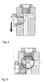
- the distance d from the center of the illumination window and the surface of the detection window for optimal flow of the particles be adapted to the size of the pipeline ( Fig. 4 ).
- the detection window it is also possible to design the detection window so that dead spaces at the 90 ° angle of the pipeline are minimal.
- the structure of the detection window can be adapted, for example in Fig. 5 shown.
- the necessary orientation of the respective light beams to each other is achieved by means of a prism.
- the measuring cell then usually has a single window, which is inserted in the wall of the pipe at the edge of the pipeline and has the prism as window glass ( Fig. 5 and 6 ).
- a sapphire or quartz glass probe with the appropriate prism geometry can be made to attach to the tubing.
- This particular embodiment has the advantage that the liquid flow can flow unhindered past the window.
- the positioning of the light source, the detector and the geometry and optical properties of the prism ensure the proper vertical orientation of the excitation light to the emission light. It is observed at a fixed angle of preferably 45 ° or 135 ° to the flow direction.
- the particle is recorded as a directed stroke.
- the thickness of the excitation light beam is preferably thinner than the diameter of the tubing.
- a thickness of not more than 5 mm is advantageous, but it depends on the diameter of the flow channel. For example, for a flow channel diameter of 5 mm, a light beam thickness of at most 1 mm is preferred. If the measuring volume is greater than the depth of field, the particles are no longer accurately measured. If only a detection of events is required, the measurement volume should be as large as possible to collect as much light as possible.
- Typical heating elements are oil tracing heating via heating channels or electric heating.
- the detector may usually register the intensity of the light emitted from the luminescent particles at a wavelength of 500 to 700 nm. If the intensity of the light emitted by the light-scattering particles is registered by the detector, this usually takes place at the excitation betting length.
- emission filters are used to selectively detect this wavelength range.
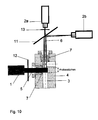
- detectors for the detection of luminescent particles and detectors for the detection of light-scattering particles can be combined (eg as in Fig. 10 shown).
- Possible detectors are, for example, CCD cameras, CMOS cameras, amplifier cameras, photomultipliers, photocells. Suitable cameras are those which are sufficiently sensitive to light in the detection wavelength range (500-700 nm).
- the Stingray camera is used by AVT.
- the advantage of a camera is that not only the luminescence intensity of the particles but also their surface can be detected.
- the light source continuously or over the integration time irradiates the sample volume of the flow channel and stimulates the particles flowing past.
- the integration time is adjusted to the size of the sample volume and to the flow rate.
- the detector records the emission light from the channel interior over the integration time and forwards this information to an image analysis unit, which is usually part of a computer.
- the analysis of the image material is typically done according to the diagram of Fig. 7 , the data is evaluated and output.
- Another object of the present invention is the use of the probe according to the invention and / or the inventive method for online monitoring of a production plant, in particular plastic production plant, sewage treatment plant.
- FIGS. 1 . 3 to 6 show possible embodiments of the device according to the invention, without limiting it thereto.
- FIG. 2 and 7 show the course of the inventive method and the sequence of image analysis in the image analysis unit, without limiting it.
- a pipe with a pipe channel of 8 mm diameter was bent at a 90 ° angle.
- a detection window was milled on one side of the pipe in front of the kink and a detection window on the side of the pipe immediately after the kink so that the detection window was open above the lower part of the piping duct and the detector could receive the liquid flow to it ,
- the distance d from the center of the illumination window and the surface of the detection window was 14 mm.
- the windows were both round with a diameter of 9 mm.
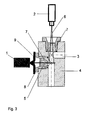
- a 10 mm thick conical sapphire window glass was mounted flush with the duct by pressure through a glass-to-metal seal ( Fig. 3 ).
- the probe was installed in the pipeline of a polycarbonate plant in which a polycarbonate melt flowed at a temperature of 300 ° C at a flow rate of 6 m / min.
- a commercially available xenon lamp (Drelloscop 255, Drello) in combination with excitation filter (HQ450 / 100 M-2P LOT Oriel) and an aperture were mounted in front of the illumination window.
- the excitation wavelength of the light beam was set to 400-500 nm using the excitation filter ,
- the light beam was focused on an average diameter of 2 mm by means of the aperture.
- a camera In front of the detection window was a camera (Stingray from AVT) in combination with an emission filter (HQ600 / 100M-2P from LOT Oriel) and a beam splitter (530DCXRU from LOT Oriel) for the selection of the recording in a wavelength range from 550 to 650 nm attached.
- the camera was mounted perpendicular to the excitation light so that it could accommodate the full diameter of the tubing channel.
- the interface of the camera was connected to an element for controlling the integration time and to an image analysis unit, both elements of a computer.
- the integration time control element In the integration time control element, the height of the sample volume (2 mm) and the flow rate were entered. An integration time of 20 ms was calculated.
- the light source continuously illuminated the sample volume at a wavelength of 400-500 nm.
- the camera took images of the sample volume in a detection wavelength range of 550 to 650 nm over the integration time under the control of the integrator 7 eit.
- the recorded data was transferred from the camera to the image analysis unit and was processed by the image analysis unit according to Fig. 7 processed.
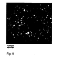
- FIGS. 8 and 9 show possible expenses after editing the data.
Abstract
Description
Die Erfindung bezieht sich auf eine Sonde und ein Verfahren zur Detektion von lumineszierenden und / oder lichtstreuenden Partikeln in Flüssigkeiten, die in einer Rohrleitung strömen.The invention relates to a probe and a method for detecting luminescent and / or light-scattering particles in liquids flowing in a pipeline.
Bei der Produktion von Kunstoffen ist die Überwachung von Produktionsprozessen von entscheidender Bedeutung, um frühzeitige Informationen über die Produktqualität zu erlangen. Insbesondere ist die Anzahl von lumineszierenden bzw. fluoreszierenden Partikeln ein entscheidender Qualitätsfaktor für die Anwendbarkeit des Kunststoffs für die Herstellung von Fertigprodukten für optische Anwendungen insbesondere optischen Speichermedien wie CD-Rom, DVDs, optischen Bauteilen, Fenstermaterialien, usw.In the production of plastics, the monitoring of production processes is crucial to obtaining early information about product quality. In particular, the number of luminescent or fluorescent particles is a crucial quality factor for the applicability of the plastic for the production of finished products for optical applications, in particular optical storage media such as CD-ROMs, DVDs, optical components, window materials, etc.
Aus dem Stand der Technik sind verschiedene Methoden zur Detektion von lumineszierenden Partikeln in CD-Roms bekannt. Z.B. wird das fertige Kunststoffganulat geschmolzen, als CD verspritzt und auf Lumineszenz untersucht. In einer weiteren Methode wird das fertige Kunststoffsgranulat aufgelöst und die Lösung durch ein Sieb gefiltert. Letztlich werden die gefilterten Partikel mittels eines elektronischen Mikroskops bewertet.Various methods for the detection of luminescent particles in CD-ROMs are known from the prior art. For example, the finished Kunststoffganulat is melted, sprayed as a CD and examined for luminescence. In another method, the finished plastic granules are dissolved and the solution is filtered through a sieve. Finally, the filtered particles are evaluated by means of an electronic microscope.
Offensichtlich sind diese Methoden aufwändig und ermöglichen keine On-Line-Kontrolle im Produktionsprozess.Obviously, these methods are laborious and do not provide on-line control in the production process.
Es bestand daher Bedarf nach einem Mittel, das in einer Rohrleitung z.B. aus einer Produktionsanlage strömende Flüssigkeit in Echtzeit alle in einem vorgegebenen Messvolumen auftretenden lumineszierenden Partikel zuverlässig und genau detektieren kann. Dabei soll die Vorrichtung einfach und robust aufgebaut sein und insbesondere Temperaturen bis zu 400 °C bei einem Druck von 40 bar standhalten können.There was therefore a need for an agent that could be used in a pipeline e.g. From a production plant flowing liquid can reliably and accurately detect in real time all occurring in a given measurement volume luminescent particles. The device should be simple and robust and in particular can withstand temperatures up to 400 ° C at a pressure of 40 bar.
Da aber das von lumineszierenden Partikeln emittierte Licht üblicherweise eine geringe Intensität aufweist, arbeitet der Detektor oft an seiner Detektionsgrenze, so dass die sich bewegenden Partikel über eine längere Detektionszeit aufgenommen werden müssen.However, since the light emitted by luminescent particles usually has a low intensity, the detector often operates at its detection limit, so that the moving particles must be taken over a longer detection time.
Ausgehend von
Die Aufgabe wird durch eine Sonde zur Detektion von lumineszierenden und / oder lichtstreuenden Partikeln in strömenden Flüssigkeiten gelöst, die eine Messzelle umfassend folgende Elemente aufweist:
- einen Rohrleitungskanal, durch den die zu vermessende Flüssigkeit strömt,
- mindestens ein transparentes Fenster in einer Wand der Rohrleitung,
- mindestens eine Lichtquelle zur Erzeugung eines dimensionierten Anregungslichtstrahls, der durch das Fenster die lumineszierenden und / oder lichtstreuenden Partikel in dem Rohrleitungskanal in einem optisch begrenzten Messvolumen anregt,
- mindestens einen Detektor, der durch das Fenster oder durch ein weiteres Fenster elektromagnetische Strahlung von den lumineszierenden und / oder lichtstreuenden Partikeln aufnimmt,
- a duct through which the liquid to be measured flows,
- at least one transparent window in a wall of the pipeline,
- at least one light source for generating a dimensioned excitation light beam which excites the luminescent and / or light-scattering particles in the pipeline channel in an optically limited measuring volume through the window,
- at least one detector which receives electromagnetic radiation from the luminescent and / or light-scattering particles through the window or through another window,
Bei der vorliegenden Erfindung können die Partikel über eine längere Detektionszeit aufgenommen werden, während der sie sich in der strömenden Flüssigkeit weiterbewegen. Jedes Partikel weist eine gerichtete Strömung auf und kann über eine längere Detektionszeit als ein Lichtpunkt oder als eine gerichtete Lichtspur aufgenommen werden, was eine zuverlässige Bildanalyse ermöglicht.In the present invention, the particles may be taken up over a longer detection time as they move in the flowing liquid. Each particle has a directional flow and can be picked up over a longer detection time than a light spot or as a directional light trail, allowing for reliable image analysis.
Ein erster Gegenstand der vorliegenden Erfindung ist daher eine Sonde zur Detektion von lumineszierenden und / oder lichtstreuenden Partikeln in strömenden Flüssigkeiten, die eine Messzelle umfassend folgende Element aufweist:
- einen Rohrleitungskanal, durch den die zu vermessende Flüssigkeit strömt,
- mindestens ein transparentes Fenster in einer Wand der Rohrleitung,
- mindestens eine Lichtquelle zur Erzeugung eines dimensionierten Anregungslichtstrahls, der durch das Fenster die lumineszierenden und / oder lichtstreuenden Partikel in dem Rohrleitungskanal in einem optisch begrenzten Lichtvolumen anregt,
- mindestens einen Detektor, der durch das Fenster oder durch ein weiteres Fenster elektromagnetische Strahlung von den lumineszierenden und / oder lichtstreuenden Partikeln aufnimmt,
- a duct through which the liquid to be measured flows,
- at least one transparent window in a wall of the pipeline,
- at least one light source for generating a dimensioned excitation light beam which excites the luminescent and / or light-scattering particles in the pipeline channel in an optically limited volume of light through the window,
- at least one detector which receives electromagnetic radiation from the luminescent and / or light-scattering particles through the window or through another window,
Vorzugsweise liegt der feste Winkel der Partikel zum Anregungslicht im Bereich von 45 bis 135 Grad.Preferably, the solid angle of the particles to the excitation light is in the range of 45 to 135 degrees.
Um eine eindeutige Identifikation eines lumineszierenden Partikels anhand der Intensität seines Emissionslichts zu ermöglichen, wird üblicherweise diese Intensität über eine bestimmte Zeit - auch Integrationszeit genannt - aufsummiert. Die Integrationszeit definiert sich als die Zeit, die ein Partikel benötigt, um das Probevolumen bei einer festen Strömungsgeschwindigkeit zu durchströmen. Bei der vorliegenden Erfindung weist der Detektor entsprechend eine Schnittstelle zu einem Element zur Steuerung der Integrationszeit auf, so dass der Detektor das von den lumineszierenden Partikeln emittierte Licht über die Zeit aufnimmt, die ein Partikel benötigt, um das Lichtvolumen bei einer definierten Strömungsgeschwindigkeit zu durchströmen. Das Element zur Steuerung der Integrationszeit ist üblicherweise Teil eines Computers.In order to enable unambiguous identification of a luminescent particle on the basis of the intensity of its emission light, this intensity is usually summed up over a specific time, also called the integration time. The integration time is defined as the time required for a particle to flow through the sample volume at a fixed flow rate. In the present invention, the detector correspondingly interfaces with an element for controlling the integration time, so that the detector receives the light emitted by the luminescent particles over the time it takes for a particle to flow through the volume of light at a defined flow rate. The element for controlling the integration time is usually part of a computer.
Typischerweise werden Rohrleitungen eines Durchmessers von 0,5 bis 50 mm, bevorzugt 4 bis 30 mm mit der erfindungsgemäßen Vorrichtung kontrolliert. Es ist dabei zu beachten, dass die Detektionsauflösung bei steigendem Rohrleitungsdurchmesser abnimmt. Entsprechend müssen die Lichtquellen und Detektoren an den Rohrleitungsdurchmcsser angepasst werden oder der Auflösungsverlust muss mit geeigneten Mittel wie z.B. hochauflösenden lichtempfindlichen Kameras, leistungsstarken Lichtquellen z.B. Laserlichtquellen oder Xenonlampen kompensiert werden.Typically, pipes of a diameter of 0.5 to 50 mm, preferably 4 to 30 mm are controlled with the device according to the invention. It should be noted that the detection resolution decreases with increasing pipe diameter. Accordingly, the light sources and detectors must be adapted to the pipe diameter or the loss of resolution must be compensated with suitable means such as high-resolution photosensitive cameras, high-performance light sources such as laser light sources or xenon lamps.
Das Material der Rohrleitung ist beliebig, üblicherweise werden Rohrleitungen aus Metall verwendet.The material of the pipeline is arbitrary, usually metal piping is used.
Typischerweise werden als Lichtquelle zur Anregung von lumineszierenden Partikeln XenonLampen in Kombination mit Anregungsftltern, Laser mit geeigneter Emissionswelle oder Hochteistungs-LEDs verwendet.Xenon lamps in combination with excitation filters, laser with suitable emission wave or high-power LEDs are typically used as the light source for excitation of luminescent particles.
Typischerweise werden die lumineszierenden Partikel mittels des Lichtstrahls bei einer Wellenlänge von 400 bis 500 nm angeregt.Typically, the luminescent particles are excited by the light beam at a wavelength of 400 to 500 nm.
Der von der Lichtquelle produzierte Anregungslichtstrahl wird üblicherweise durch ein Fenster eingebracht in der Rohrleitungswand über den kompletten Rohrleitungsdurchmesser des Rohrleitungskanals eingestrahlt. Die Dimensionen des Anregungslichtstrahls definieren das optisch begrenzte Messvolumen. Der besondere Vorteil dabei ist, dass durch die Bildaufnahme eines kleinen Abschnitts (Messvolumen) einer Rohrleitung über die Zeit der komplette Inhalt einer Rohrleitung erfasst werden kann. Bei Bedarf wird die Geometrie des Anregungslichtstrahls mit Hilfe von Zylinderlinsen oder LichEleiterquerschnittswandlern gestaltet.The excitation light beam produced by the light source is usually introduced through a window in the pipe wall over the entire pipe diameter of the pipe duct. The dimensions of the excitation light beam define the optically limited measurement volume. The particular advantage of this is that the complete content of a pipeline can be recorded over time by taking a picture of a small section (measuring volume) of a pipeline. If necessary, the geometry of the excitation light beam is designed using cylindrical lenses or LichEleiterquerschnittswandlern.
Üblicherweise wird die senkrechte Orientierung des dimensionierten Anregungslichtstrahls zu dem von den lumineszierenden Partikeln emittierten Licht durch eine senkrechte Orientierung der Lichtquelle und des Detektors zueinander gewährleistet. Alternativ kann mittels Prismen und Spiegeln die nötige Orientierung der jeweiligen Lichtstrahlen zueinander erreicht werden.Usually, the perpendicular orientation of the dimensioned excitation light beam to the light emitted by the luminescent particles is ensured by a perpendicular orientation of the light source and the detector to each other. Alternatively, the necessary orientation of the respective light beams to each other can be achieved by means of prisms and mirrors.
In einer ersten Ausführungsform der erfindungsgemäßen Sonde befinden sich in der Rohrleitungswand ein transparentes Fenster zur Beleuchtung des Rohrleitungskanals (Beleuchtungsfenster) mit dem Anregungslicht und ein weiteres transparentes Fenster zur Aufnahme des Einissionslichts mittels des Detektors (Detektionsfenster). In dieser besonderen Ausführungsform (siehe
Bei dieser Ausführungsform der Erfindung ist es vorteilhaft, wenn das Lichtvolumen maximal doppelt so hoch wie der Tiefenschärfenbereieli des Detektors ist, typischerweise wird der Anregungslichtstrahl auf einen Durchmesser von 100 µm bis 10 mm, bevorzugt 150 µm bis 3 mm fokussiert. Ist das Messvolumen größer als der Tiefenschärfenbereich, werden die Partikel nicht mehr exakt vermessen. Ist lediglich eine Detektion von Ereignissen gefordert, sollte das Messvolumen so groß wie nur möglich sein, um möglichst viel Licht zu sammeln.In this embodiment of the invention, it is advantageous if the light volume is at most twice as high as the depth of field of the detector, typically the excitation light beam is focused to a diameter of 100 .mu.m to 10 mm, preferably 150 .mu.m to 3 mm. If the measuring volume is greater than the depth of field, the particles are no longer accurately measured. If only a detection of events is required, the measurement volume should be as large as possible to collect as much light as possible.
Da der Winkel der Rohrleitung die Richtung des Flüssigkeitsstroms in der Leitung auch vor dem Knick beeinflusst, ist es vorteilhaft, wenn der Aufbau der Messzelle das laminare Strömen der Partikel unbehindert innerhalb des Messvolumens, d.h. ohne tote Räume und bei konstanter Geschwindigkeit, geradlinig unterstützt. Hierfür können verschiedene Mittel einzeln oder miteinander kombiniert verwendet werden.Since the angle of the pipe affects the direction of the liquid flow in the pipe, even before the bend, it is advantageous if the construction of the measuring cell permits the laminar flow of the particles unhindered within the measuring volume, i. without dead spaces and at constant speed, supported in a straight line. For this purpose, different agents can be used individually or combined with each other.
Es ist z.B. bevorzugt, dass das Fensterglas in die Rohrleitungswand bündig mit dem Rohrleitungskanal befestigt ist. Die Form des Fensters ist beliebig, üblicherweise rund mit einem Durchmesser von 2 bis 100 mm. Alternativ kann eine Sonde aus Saphir oder Quarzglas angefertigt werden, die an die Rohrleitung befestigt wird.It is e.g. preferred that the window glass is fixed in the pipe wall flush with the pipe duct. The shape of the window is arbitrary, usually round with a diameter of 2 to 100 mm. Alternatively, a sapphire or quartz glass probe can be made to attach to the tubing.
Für die Anwendbarkeit in einer Kunststoffsproduktionsanlage müssen die Fenster dem Strömen einer Schmelze bei einer Temperatur von bis zu 400 °C und einem Druck von I bis 250 bar standhalten. Typischerweise besteht das Fenster aus Saphir bzw. Quarzglas, bevorzugt Saphir wegen seiner besonderen Festigkeit, weist eine Dicke von 10 mm auf und ist - wie z.B. in
Es ist außerdem bevorzugt, dass die Distanz d ab dem Zentrum des Beleuchtungsfensters und die Oberfläche des Detektionsfenster für ein optimales Strömen der Partikel an die Größe der Rohrleitung angepasst wird (
Es ist auch möglich, das Detektionsfenster so zu gestalten, dass tote Räume in dem 90°-Winkel der Rohrleitung minimal sind. Hierfür kann der Aufbau des Detektionstensters angepasst werden wie z.B. in
In einer zweiten Ausführungsform der erfindungsgemäßen Sonde wird die nötige Orientierung der jeweiligen Lichtstrahlen zueinander mittels eines Prismas erreicht. Üblicherweise weist dann die Messzelle ein einziges Fenster auf, das am Rand der Rohrleitung in der Rohrleitungswand eingesetzt ist und als Fensterglas das Prisma aufweist (
Diese besondere Ausführungsform hat den Vorteil, dass der Flüssigkeitsstrom unbehindert an dem Fenster vorbei fließen kann. Die Positionierung der Lichtquelle, des Detektors und die Geometrie und optischen Eigenschaften des Prismas sichern die passende senkrechte Orientierung des Anregungslichts zu dem Emissionslicht. Beobachtet wird in einem festen Winkel von bevorzugt 45° bzw. 135° zur Strömungsrichtung. Bei dieser Ausführung wird das Partikel als gerichteter Strich aufgenommen.This particular embodiment has the advantage that the liquid flow can flow unhindered past the window. The positioning of the light source, the detector and the geometry and optical properties of the prism ensure the proper vertical orientation of the excitation light to the emission light. It is observed at a fixed angle of preferably 45 ° or 135 ° to the flow direction. In this embodiment, the particle is recorded as a directed stroke.
Bei der Prismenausführung ist die Dicke des Anregungslichtstrahls vorzugsweise dünner als der Durchmesser der Rohrleitung. Vorteilhaft ist eine Dicke von maximal 5 mm, die aber von dem Durchmesser des Strömungskanal abhängt. Beispielsweise wird für einen Strömungskanaldurchmesser von 5 mm eine Lichtstrahldicke von maximal 1 mm bevorzugt. Ist das Messvolumen größer als der Tiefenschärfenbereich, werden die Partikel nicht mehr exakt vermessen. Ist lediglich eine Detektion von Ereignissen gefordert, sollte das Messvolumen so groß wie nur möglich sein, um möglichst viel Licht zu sammeln.In prismatic design, the thickness of the excitation light beam is preferably thinner than the diameter of the tubing. A thickness of not more than 5 mm is advantageous, but it depends on the diameter of the flow channel. For example, for a flow channel diameter of 5 mm, a light beam thickness of at most 1 mm is preferred. If the measuring volume is greater than the depth of field, the particles are no longer accurately measured. If only a detection of events is required, the measurement volume should be as large as possible to collect as much light as possible.
Für die beschriebenen Ausführungsformen 1 und 2 kann es vorteilhaft sein, die Messzelle direkt mittels Heizungselemente zu temperieren, so dass die Temperatur der vorbei strömenden Flüssigkeit konstant gehalten werden kann. Typische Heizungselemente sind Ölbegleitheizung über Heizkanäle oder elektrische Beheizung.For the described
Bei der vorliegenden Erfindung kann der Detektor die Intensität des von den lumineszierenden Partikeln emittierten Lichts üblicherweise bei einer Wellenlänge von 500 bis 700 nm registrieren. Wird die Intensität des von den lichtstreuenden Partikeln emittierten Lichts vom Detektor registriert, findet dies üblicherweise bei der Anregungswettenlänge statt. Gegebenenfalls werden Emissionsfilter eingesetzt, um diesen Wellenlängenbereich selektiv zu erfassen.In the present invention, the detector may usually register the intensity of the light emitted from the luminescent particles at a wavelength of 500 to 700 nm. If the intensity of the light emitted by the light-scattering particles is registered by the detector, this usually takes place at the excitation betting length. Optionally, emission filters are used to selectively detect this wavelength range.
Es ist auch möglich, mehrere Detektoren einzusetzen, wobei Detektoren zur Detektion von lumineszierenden Partikeln und Detektoren zur Detektion von lichtstreuenden Partikeln kombiniert werden können (z.B. wie in
Mögliche Detektoren sind beispielsweise CCD-Kameras, CMOS-Kameras, Verstärkerkameras, Photomultiplier, Photozellen. Geeignete Kameras sind welche, die in dem Detektionswellenbereich (500-700 nm) ausreichend lichtempfindlich sind. Beispielsweise wird die Kamera Stingray von der Firma AVT verwendet. Der Vorteil einer Kamera besteht darin, dass nicht nur die Lumineszenzintensität der Partikel sondern auch ihre Fläche erfasst werden kann.Possible detectors are, for example, CCD cameras, CMOS cameras, amplifier cameras, photomultipliers, photocells. Suitable cameras are those which are sufficiently sensitive to light in the detection wavelength range (500-700 nm). For example, the Stingray camera is used by AVT. The advantage of a camera is that not only the luminescence intensity of the particles but also their surface can be detected.
Erfindungsgemäß strahlt die Lichtquelle kontinuierlich oder über die Integrationszeit das Probevolumen des Strömungskanals an und regt die vorbei fließenden Partikel an.According to the invention, the light source continuously or over the integration time irradiates the sample volume of the flow channel and stimulates the particles flowing past.
Üblicherweise wird die Integrationszeit an die Größe des Probenvolumens und an die Strömungsgeschwindigkeit angepasst.Usually, the integration time is adjusted to the size of the sample volume and to the flow rate.
Der Detektor nimmt über die Integrationszeit das Emissionslicht aus dem Kanalinneren auf und leitet diese Information an eine Bildanalyseeinheit, welche üblicherweise Teil eines Computers ist, weiter.The detector records the emission light from the channel interior over the integration time and forwards this information to an image analysis unit, which is usually part of a computer.
Die Analyse des Bildmaterials erfolgt typischerweise nach dem Diagramm der
Ein weiterer Gegenstand der vorliegenden Erfindung ist daher ein Verfahren zur Detektion von iumincszierenden und / oder liehtstreuenden Partikeln in strömenden Flüssigkeiten mit folgenden Schritten:
- Eingabe der Höhe des Probevolumens und Eingabe der Strömungsgeschwindigkeit sowie Berechnung der Integrationszeit in ein Element zur Steuerung der Integrationszeit,
- Lichtanregung durch eine Lichtquelle,
- Detektion von Emissionsstrahlung über die lntegrationszeitmittels eines Detektors,
- Analyse der Detektionsdaten mittels einer Bildanalyseeinheil
- Ausgabe der Anzahl von Partikeln und/ oder Größenverteilung von Partikein und/ oder Intensitätsverteilung von Partikeln pro Volumen und / oder pro Gewicht und /oder Ausgabe eines Sammelbildes von lumineszierenden Partikeln über eine bestimmte Zeit.
- Input of the height of the sample volume and input of the flow velocity as well as calculation of the integration time into an element for controlling the integration time,
- Light excitation by a light source,
- Detection of emission radiation over the integration time by means of a detector,
- Analysis of the detection data by means of an image analysis unit
- Output of the number of particles and / or size distribution of particle size and / or intensity distribution of particles per volume and / or weight and / or output of a collection image of luminescent particles over a certain time.
Ein weiterer Gegenstand der vorliegenden Erfindung ist die Verwendung der erfindungsgemäßen Sonde und / oder des erfindungsgemäßen Verfahrens zur Online-Überwachung einer Produktionsanlage, insbesondere Kunststoffsproduktionsanlage, Kläranlage.Another object of the present invention is the use of the probe according to the invention and / or the inventive method for online monitoring of a production plant, in particular plastic production plant, sewage treatment plant.
Die
- Fig. 1:Fig. 1:
- erfindungsgemäße Sonde anhand der Ausführungsfortu 1Probe according to the invention with reference to Ausführungsfortu first
- Fig.2:Figure 2:
- Verfahrensdiagrammprocess diagram
- Fig. 3:3:
-
Ausführungsform 1
Embodiment 1 - Fig. 4:4:
-
Optimierung des Distanz d bei der Ausführungsform 1Optimization of the distance d in the
embodiment 1 - Fig. 5:Fig. 5:
-
Fenstervariante der Ausführungsform 1Window variant of the
embodiment 1 - Fig. 6a:6a:
-
Seitenansicht der Ausführungsform 2 mit dem PrismaSide view of the
embodiment 2 with the prism - Fig. 6b:Fig. 6b:
-
Sicht von oben der Ausführungsform 2 mit dem PrismaView from above of
embodiment 2 with the prism - Fig. 7:Fig. 7:
- Diagramm der Bildanalyse in der BildanalyseeinheitDiagram of the image analysis in the image analysis unit
- Fig. 8:Fig. 8:
- Ausgabe der Anzahl von fluoreszierenden Partikeln pro Gramm Schmelze über die ZeitOutput of the number of fluorescent particles per gram of melt over time
- Fig. 9:Fig. 9:
- Sammelbild der fluoreszierenden Partikeln über 6 Stunden.Collective image of the fluorescent particles over 6 hours.
- Fig. 10:Fig. 10:
- Sonde zur gleichzeitigen Detektion von lumineszierenden Partikeln und lichtstreuenden PartikelnProbe for the simultaneous detection of luminescent particles and light-scattering particles
- 11
- Lichtquellelight source
- 22
- Detektordetector
- 2a2a
- Detektor zur Detektion von lumineszierenden PartikelnDetector for the detection of luminescent particles
- 2b2 B
- Detektor zur Detektion von lichtstreuenden Partikeln Detector for detecting light-scattering particles
- 33
- RohrleitungskanalPipeline channel
- 44
- RohrleitungswandPipe wall
- 55
- AnregungslichtstrahlExcitation light beam
- 66
- Emissionslichtemission light
- 77
- Fensterglaswindow glass
- 88th
- Glas-Metall-DichtungGlass-metal seal
- 99
- Aperturaperture
- 1010
- Prismaprism
- 1111
- Dichriotischer Spiegel 530nmDichroic mirror 530nm
- 1212
- Anregungsfilter 400-500nmExcitation filter 400-500nm
- 1313
- Fluoreszenzfilter 550-650nmFluorescence filter 550-650nm
Eine Rohrleitung mit einem Rohrleitungskanal von 8 mm Durchmesser wurde in einem 90°-Winkel geknickt.A pipe with a pipe channel of 8 mm diameter was bent at a 90 ° angle.
In der Rohrleitungswand wurden an einer Seite der Rohrleitung vor dem Knick ein Beleuchtungsfenster und an der Seite der Rohrleitung unmittelbar nach dem Knick ein Detektionsfenster gefräst, so dass das Detektionsfenster über dem unteren Teil des Rohrleitungsleitungskanals offen war und der Detektor den zu sich fließenden Flüssigkeitsstrom aufnehmen konnte.In the pipe wall, a detection window was milled on one side of the pipe in front of the kink and a detection window on the side of the pipe immediately after the kink so that the detection window was open above the lower part of the piping duct and the detector could receive the liquid flow to it ,
Die Distanz d ab dem Zentrum des Beleuchtungsfensters und die Oberfläche des Detektionsfensters betrug 14 mm.The distance d from the center of the illumination window and the surface of the detection window was 14 mm.
Die Fenster waren beide rund mit einem Durchmesser von 9 mm. In jedem Fenster wurde ein 10 mm dickes konisch geformtes Fensterglas aus Saphir bündig mit dem Rohrleitungskanal durch Druck mittels einer Glas-Metall-Dichtung befestigt (
Die Sonde wurde in die Rohrleitung einer Polycarbonatanlage eingebaut, in der eine Polycarbonatschmelze bei einer Temperatur von 300 °C mit einer Strömungsgeschwindigkeit von 6 m / min floss.The probe was installed in the pipeline of a polycarbonate plant in which a polycarbonate melt flowed at a temperature of 300 ° C at a flow rate of 6 m / min.
Vor dem Beleuchtungsfenster wurden eine kommerziell verfügbare Xenon Lampe (Drelloscop 255, der Firma Drello) in Kombination mit Anregungsfilter (HQ450/100 M-2P LOT Oriel) sowie eine Apertur befestigt Die Anregungswcllcnlänge des Lichtstrahls wurde mit Hilfe des Anregungsfilters auf 400-500 nm eingestellt. Der Lichtstrahl wurde auf einem Durchschnittsdurchmesser von 2 mm mittels der Apertur fokussiert.A commercially available xenon lamp (Drelloscop 255, Drello) in combination with excitation filter (HQ450 / 100 M-2P LOT Oriel) and an aperture were mounted in front of the illumination window. The excitation wavelength of the light beam was set to 400-500 nm using the excitation filter , The light beam was focused on an average diameter of 2 mm by means of the aperture.
Vor dem Detektionsfenster wurde eine Kamera (Stingray von der Firma AVT) in Kombination mit einem Emissionsfilter (HQ600/100M-2P der Firma LOT Oriel) und eines Strahlteilers (530DCXRU der Firma LOT Oriel) zur Selektion der Aufnahme in einem Wellenlängenbereich von 550 bis 650 nm befestigt. Die Kamera wurde senkrecht zum Anregungslicht befestigt, so dass sie den kompletten Durchmesser des Rohrleitungskanals aufnehmen konnte.In front of the detection window was a camera (Stingray from AVT) in combination with an emission filter (HQ600 / 100M-2P from LOT Oriel) and a beam splitter (530DCXRU from LOT Oriel) for the selection of the recording in a wavelength range from 550 to 650 nm attached. The camera was mounted perpendicular to the excitation light so that it could accommodate the full diameter of the tubing channel.
Die Schnittstelle der Kamera wurde mit einem Element zur Steuerung der Integrationszeit und mit einer Bildanalyseeinheit, beide Elemente eines Computers, verbunden.The interface of the camera was connected to an element for controlling the integration time and to an image analysis unit, both elements of a computer.
In dem Element zur Steuerung der Integrationszeit wurden die Höhe des Probevolumens (2 mm) und die Strömungsgeschwindigkeit eingegeben. Eine lntegrationszeit von 20 ms wurde berechnet.In the integration time control element, the height of the sample volume (2 mm) and the flow rate were entered. An integration time of 20 ms was calculated.
Die Lichtquelle beleuchtete das Probenvolumen bei einer Wellenlänge von 400-500 nm kontinuierlich.The light source continuously illuminated the sample volume at a wavelength of 400-500 nm.
Die Kamera nahm Bilder des Probenvolumen in einem Detektionswellenlängenbereich von 550 bis 650 nm über die Integrationszeit gesteuert durch das Element zur Steuerung der Integratiotis7eit auf.The camera took images of the sample volume in a detection wavelength range of 550 to 650 nm over the integration time under the control of the integrator 7 eit.
Die aufgenommenen Daten wurden von der Kamera in die Bildanalyseeinheit übertragen und wurden von der Bildanalyseeinheit gemäß
Die
Claims (12)
wobei die Messzelle so aufgebaut ist, dass der dimensionierte Anregungslichtstrahl und das von den lumineszierenden und / oder lichtstreuenden Partikeln emittierte Licht senkrecht zueinander orientiert sind und jedes Partikel sich innerhalb des Messvolumens parallel zum Flüssigkeitsstrom, geradlinig mit einem festen Winkel zum Anregungslicht bewegt.
wherein the measuring cell is constructed such that the dimensioned excitation light beam and the light emitted by the luminescent and / or light-scattering particles are oriented perpendicular to each other and each particle moves within the measurement volume parallel to the liquid flow, rectilinearly at a fixed angle to the excitation light.
Priority Applications (12)
| Application Number | Priority Date | Filing Date | Title |
|---|---|---|---|
| EP09015341A EP2333515A1 (en) | 2009-12-11 | 2009-12-11 | Device for detecting luminous and/or light-diffusing particles in flowing liquids |
| CN2010800561275A CN102652257A (en) | 2009-12-11 | 2010-12-06 | Means for detecting luminescent and/or light-scattering particles in flowing liquids |
| PCT/EP2010/068998 WO2011069976A1 (en) | 2009-12-11 | 2010-12-06 | Means for detecting luminescent and/or light-scattering particles in flowing liquids |
| SG2012039756A SG181139A1 (en) | 2009-12-11 | 2010-12-06 | Means for detecting luminescent and/or light-scattering particles in flowing liquids |
| EP10790917A EP2510333A1 (en) | 2009-12-11 | 2010-12-06 | Means for detecting luminescent and/or light-scattering particles in flowing liquids |
| CA2783989A CA2783989A1 (en) | 2009-12-11 | 2010-12-06 | Means for detecting luminescent and/or light-scattering particles in flowing liquids |
| AU2010329979A AU2010329979A1 (en) | 2009-12-11 | 2010-12-06 | Means for detecting luminescent and/or light-scattering particles in flowing liquids |
| KR1020127017866A KR20120092188A (en) | 2009-12-11 | 2010-12-06 | Means for detecting luminescent and/or light-scattering particles in flowing liquids |
| US13/514,914 US20120281203A1 (en) | 2009-12-11 | 2010-12-06 | Means for detecting luminescent and/or light-scattering particles in flowing liquids |
| JP2012542498A JP2013513789A (en) | 2009-12-11 | 2010-12-06 | Means for detecting luminescent particles or light scattering particles in a flowing liquid |
| TW099143147A TW201135210A (en) | 2009-12-11 | 2010-12-10 | Means for detecting luminescent and/or light-scattering particles in flowing liquids |
| IN5124DEN2012 IN2012DN05124A (en) | 2009-12-11 | 2012-06-11 |
Applications Claiming Priority (1)
| Application Number | Priority Date | Filing Date | Title |
|---|---|---|---|
| EP09015341A EP2333515A1 (en) | 2009-12-11 | 2009-12-11 | Device for detecting luminous and/or light-diffusing particles in flowing liquids |
Publications (1)
| Publication Number | Publication Date |
|---|---|
| EP2333515A1 true EP2333515A1 (en) | 2011-06-15 |
Family
ID=42077159
Family Applications (2)
| Application Number | Title | Priority Date | Filing Date |
|---|---|---|---|
| EP09015341A Withdrawn EP2333515A1 (en) | 2009-12-11 | 2009-12-11 | Device for detecting luminous and/or light-diffusing particles in flowing liquids |
| EP10790917A Withdrawn EP2510333A1 (en) | 2009-12-11 | 2010-12-06 | Means for detecting luminescent and/or light-scattering particles in flowing liquids |
Family Applications After (1)
| Application Number | Title | Priority Date | Filing Date |
|---|---|---|---|
| EP10790917A Withdrawn EP2510333A1 (en) | 2009-12-11 | 2010-12-06 | Means for detecting luminescent and/or light-scattering particles in flowing liquids |
Country Status (11)
| Country | Link |
|---|---|
| US (1) | US20120281203A1 (en) |
| EP (2) | EP2333515A1 (en) |
| JP (1) | JP2013513789A (en) |
| KR (1) | KR20120092188A (en) |
| CN (1) | CN102652257A (en) |
| AU (1) | AU2010329979A1 (en) |
| CA (1) | CA2783989A1 (en) |
| IN (1) | IN2012DN05124A (en) |
| SG (1) | SG181139A1 (en) |
| TW (1) | TW201135210A (en) |
| WO (1) | WO2011069976A1 (en) |
Cited By (1)
| Publication number | Priority date | Publication date | Assignee | Title |
|---|---|---|---|---|
| CN105143561A (en) * | 2013-03-28 | 2015-12-09 | Ihc系统股份有限公司 | Measurement device for performing measurement on a mixture of water and collected material |
Families Citing this family (18)
| Publication number | Priority date | Publication date | Assignee | Title |
|---|---|---|---|---|
| SE537725C2 (en) * | 2013-04-02 | 2015-10-06 | Btg Instr Ab | Method for determining properties of heterogeneous media |
| US8927922B2 (en) * | 2013-05-21 | 2015-01-06 | Aquionics, Inc. | Fluid diagnostic devices and methods of using the same |
| DE102013211885A1 (en) * | 2013-06-24 | 2014-12-24 | Siemens Aktiengesellschaft | Particle detector and method for the detection of particles |
| CN104931465B (en) * | 2014-03-21 | 2018-02-09 | 中国石油化工股份有限公司 | For the device and method for the dissolved state for monitoring the oil gas water in dissolution kettle |
| JP2015227805A (en) * | 2014-05-30 | 2015-12-17 | アズビル株式会社 | Device and method for detecting particle in liquid |
| CN105181374A (en) * | 2015-10-09 | 2015-12-23 | 绍兴文理学院 | Boiler flue gas tourmalinite purifier scattering online test board |
| CN107091796A (en) * | 2017-06-14 | 2017-08-25 | 中央民族大学 | The optical system that across particle diameter size granule level is matched somebody with somebody and its is distributed in a kind of measurement pipe stream |
| US11187661B2 (en) | 2017-07-05 | 2021-11-30 | Saudi Arabian Oil Company | Detecting black powder levels in flow-lines |
| CN107677686B (en) * | 2017-09-28 | 2021-01-26 | 京东方科技集团股份有限公司 | Light transmission window integrated device and equipment adopting same |
| CN108414480B (en) * | 2018-01-26 | 2023-03-24 | 中国海洋石油集团有限公司 | Crude oil fluorescence measuring device and method |
| US10983044B2 (en) | 2018-06-26 | 2021-04-20 | Arometrix, Inc. | Device, system and method for in-situ optical monitoring and control of extraction and purification of plant materials |
| CN109084683B (en) * | 2018-10-19 | 2023-11-28 | 广东中道创意科技有限公司 | Particulate matter detection device |
| TWI744716B (en) * | 2018-11-16 | 2021-11-01 | 美商粒子監測系統有限公司 | Particle detection system and method for characterizing liquid sample |
| DE102018131059A1 (en) * | 2018-12-05 | 2020-06-10 | SIKA Dr. Siebert & Kühn GmbH & Co. KG | Flow measuring method and flow measuring device for optical flow measurement |
| DE102018221700A1 (en) * | 2018-12-13 | 2020-06-18 | Robert Bosch Gmbh | Method for the detection of particles or aerosol in a flowing fluid, computer program and electrical storage medium |
| CN111323360B (en) * | 2018-12-14 | 2022-07-05 | 中国科学院深圳先进技术研究院 | Image acquisition equipment and detection device for particles in liquid |
| KR102098701B1 (en) * | 2019-03-12 | 2020-04-08 | 주식회사 지씨에스월드 | Apparatus for detecting dust and analyzing shape thereof in liquid using image sensor and method thereof |
| CN113959947A (en) * | 2021-10-25 | 2022-01-21 | 山东大学 | Single-particle multi-modal flow imaging detection device and method based on two-dimensional light scattering |
Citations (9)
| Publication number | Priority date | Publication date | Assignee | Title |
|---|---|---|---|---|
| US5489977A (en) * | 1993-08-11 | 1996-02-06 | Texaco Inc. | Photomeric means for monitoring solids and fluorescent material in waste water using a falling stream water sampler |
| JPH08178831A (en) * | 1994-12-19 | 1996-07-12 | Rion Co Ltd | Light scattering particle detector |
| JPH10115584A (en) * | 1996-10-11 | 1998-05-06 | Dkk Corp | Fluorescent flow cell |
| US6309886B1 (en) * | 1999-06-04 | 2001-10-30 | The Regents Of The University Of California | High throughput analysis of samples in flowing liquid |
| DE10201541A1 (en) | 2002-01-17 | 2003-08-14 | Bayer Ag | Exchangeable process window |
| JP2005300375A (en) * | 2004-04-13 | 2005-10-27 | Sanki Eng Co Ltd | Waste water pollution concentration detection system, waste water pollution detection device, and piping unit for waste water pollution detection |
| WO2006136147A2 (en) | 2005-06-19 | 2006-12-28 | Stiftung Alfred-Wegener-Institut Für Polar- Und Meeresforschung | Device for particle detection in a diffuser with a limited depth |
| JP2007071548A (en) * | 2005-09-02 | 2007-03-22 | Nippon Telegr & Teleph Corp <Ntt> | Prism/liquid reservoir integrated type chip for measuring surface plasmon resonance spectrum, its manufacturing method and surface plasmon resonance measuring instrument using prism/liquid reservoir integrated type chip |
| US20080019658A1 (en) * | 2005-10-03 | 2008-01-24 | Creatv Mictrotech, Inc. | Sensitive emission light gathering and flow through detection system |
Family Cites Families (8)
| Publication number | Priority date | Publication date | Assignee | Title |
|---|---|---|---|---|
| DK66992D0 (en) * | 1992-05-21 | 1992-05-21 | Faxe Kalkbrud Aktieselskabet | SENSOR |
| US5608517A (en) * | 1995-02-28 | 1997-03-04 | Thermo Separation Products Inc. | Flow cell and method for making same |
| US6473176B2 (en) * | 1999-01-25 | 2002-10-29 | Amnis Corporation | Imaging and analyzing parameters of small moving objects such as cells |
| US7280207B2 (en) * | 2001-07-25 | 2007-10-09 | Applera Corporation | Time-delay integration in a flow cytometry system |
| US6809810B2 (en) * | 2001-10-04 | 2004-10-26 | Applera Corporation | Detection cell |
| DE102005021179A1 (en) * | 2005-05-06 | 2006-11-09 | Lt-Research Gmbh | Evaluating signal from light detector in focussed beam reflectance measuring device, by using state machine and increasing secant length while logical one exists at output of detections stage |
| JP2009258071A (en) * | 2008-03-28 | 2009-11-05 | Fujifilm Corp | Particle analyzer and particle analysis method |
| CN101278829A (en) * | 2008-05-26 | 2008-10-08 | 上海理工大学 | Portable in vivo flow cytometry |
-
2009
- 2009-12-11 EP EP09015341A patent/EP2333515A1/en not_active Withdrawn
-
2010
- 2010-12-06 WO PCT/EP2010/068998 patent/WO2011069976A1/en active Application Filing
- 2010-12-06 EP EP10790917A patent/EP2510333A1/en not_active Withdrawn
- 2010-12-06 SG SG2012039756A patent/SG181139A1/en unknown
- 2010-12-06 AU AU2010329979A patent/AU2010329979A1/en not_active Abandoned
- 2010-12-06 US US13/514,914 patent/US20120281203A1/en not_active Abandoned
- 2010-12-06 CA CA2783989A patent/CA2783989A1/en not_active Abandoned
- 2010-12-06 KR KR1020127017866A patent/KR20120092188A/en not_active Application Discontinuation
- 2010-12-06 CN CN2010800561275A patent/CN102652257A/en active Pending
- 2010-12-06 JP JP2012542498A patent/JP2013513789A/en active Pending
- 2010-12-10 TW TW099143147A patent/TW201135210A/en unknown
-
2012
- 2012-06-11 IN IN5124DEN2012 patent/IN2012DN05124A/en unknown
Patent Citations (9)
| Publication number | Priority date | Publication date | Assignee | Title |
|---|---|---|---|---|
| US5489977A (en) * | 1993-08-11 | 1996-02-06 | Texaco Inc. | Photomeric means for monitoring solids and fluorescent material in waste water using a falling stream water sampler |
| JPH08178831A (en) * | 1994-12-19 | 1996-07-12 | Rion Co Ltd | Light scattering particle detector |
| JPH10115584A (en) * | 1996-10-11 | 1998-05-06 | Dkk Corp | Fluorescent flow cell |
| US6309886B1 (en) * | 1999-06-04 | 2001-10-30 | The Regents Of The University Of California | High throughput analysis of samples in flowing liquid |
| DE10201541A1 (en) | 2002-01-17 | 2003-08-14 | Bayer Ag | Exchangeable process window |
| JP2005300375A (en) * | 2004-04-13 | 2005-10-27 | Sanki Eng Co Ltd | Waste water pollution concentration detection system, waste water pollution detection device, and piping unit for waste water pollution detection |
| WO2006136147A2 (en) | 2005-06-19 | 2006-12-28 | Stiftung Alfred-Wegener-Institut Für Polar- Und Meeresforschung | Device for particle detection in a diffuser with a limited depth |
| JP2007071548A (en) * | 2005-09-02 | 2007-03-22 | Nippon Telegr & Teleph Corp <Ntt> | Prism/liquid reservoir integrated type chip for measuring surface plasmon resonance spectrum, its manufacturing method and surface plasmon resonance measuring instrument using prism/liquid reservoir integrated type chip |
| US20080019658A1 (en) * | 2005-10-03 | 2008-01-24 | Creatv Mictrotech, Inc. | Sensitive emission light gathering and flow through detection system |
Cited By (2)
| Publication number | Priority date | Publication date | Assignee | Title |
|---|---|---|---|---|
| CN105143561A (en) * | 2013-03-28 | 2015-12-09 | Ihc系统股份有限公司 | Measurement device for performing measurement on a mixture of water and collected material |
| CN105143561B (en) * | 2013-03-28 | 2017-05-10 | Ihc系统股份有限公司 | Measurement device, related ship and method |
Also Published As
| Publication number | Publication date |
|---|---|
| JP2013513789A (en) | 2013-04-22 |
| IN2012DN05124A (en) | 2015-10-23 |
| CA2783989A1 (en) | 2011-06-16 |
| EP2510333A1 (en) | 2012-10-17 |
| KR20120092188A (en) | 2012-08-20 |
| SG181139A1 (en) | 2012-07-30 |
| WO2011069976A1 (en) | 2011-06-16 |
| TW201135210A (en) | 2011-10-16 |
| AU2010329979A1 (en) | 2012-07-05 |
| CN102652257A (en) | 2012-08-29 |
| US20120281203A1 (en) | 2012-11-08 |
Similar Documents
| Publication | Publication Date | Title |
|---|---|---|
| EP2333515A1 (en) | Device for detecting luminous and/or light-diffusing particles in flowing liquids | |
| DE4437758B4 (en) | Image analysis method and apparatus for flow particles | |
| US20200158545A1 (en) | Automated Set-Up for Cell Sorting | |
| EP2864758B1 (en) | Sensor and methods for measuring particles in media | |
| DE3705876C2 (en) | Flow cytometry method and apparatus | |
| DE69920284T2 (en) | DETECTOR FOR LASER-INDUCED FLUORESCENT AND APPLICATION METHOD FOR THIS DEVICE | |
| DE602005002625T2 (en) | SYSTEM AND METHOD FOR MULTIPLE-LASER TRIGGERING | |
| DE3012242A1 (en) | PARABOLIC CELL ANALYZER | |
| DE112015001461T5 (en) | Microscope viewing container and viewing device | |
| WO2008125204A1 (en) | Method and arrangement for positioning a light sheet in the focal plane of a detection optic | |
| DE60223370T2 (en) | INTERCHANGEABLE FLOW CELL ASSEMBLY WITH HANGING CAPILLARY | |
| DE102004008762B4 (en) | Method and device for detecting and identifying bioparticles | |
| EP3067685B1 (en) | Device for taking images of a measuring volume in a container | |
| DE202019101669U1 (en) | Device for field flux fractionation in combination with Raman spectroscopy | |
| EP2647982A2 (en) | Method and device for determining a critical angle of an excitation light beam | |
| DE19744246A1 (en) | Portable videomicroscopic observation of suspended particles in gas or liquid stream | |
| EP1756547B1 (en) | Device for measuring light emitted by microscopically small particles or biological cells | |
| DE102017119284B4 (en) | particle sensor | |
| DE10221564A1 (en) | Photoluminescence analyzer for chemical and biological sample screening uses a high intensity homogeneous line image as illumination source, and has multiple sensor scanning of the image | |
| DE10239767B4 (en) | Apparatus and method for determining the aerodynamic behavior of particles in aerosols | |
| WO2016074995A1 (en) | Flow measuring method | |
| DE102007059167A1 (en) | Pipette tip for use in e.g. pipetting device in laboratory, has wall comprising transparent region, where transparent region is formed as coplanar measuring windows in optical quality | |
| DE102010012580A1 (en) | Device for time-resolved measurement of fluorescence signals in flow-cytometric investigation of e.g. cells, has detector with measuring point comprising local displacements that are changed during operation of device | |
| DE19906047A1 (en) | Detection of biotic contamination on surfaces in connection with e.g. food, semiconductors or medicine, by measuring indicative fluorescence in a specific waveband | |
| DE102019106194B4 (en) | Device for the spectroscopic determination of the binding kinetics of an analyte |
Legal Events
| Date | Code | Title | Description |
|---|---|---|---|
| PUAI | Public reference made under article 153(3) epc to a published international application that has entered the european phase |
Free format text: ORIGINAL CODE: 0009012 |
|
| AK | Designated contracting states |
Kind code of ref document: A1 Designated state(s): AT BE BG CH CY CZ DE DK EE ES FI FR GB GR HR HU IE IS IT LI LT LU LV MC MK MT NL NO PL PT RO SE SI SK SM TR |
|
| AX | Request for extension of the european patent |
Extension state: AL BA RS |
|
| STAA | Information on the status of an ep patent application or granted ep patent |
Free format text: STATUS: THE APPLICATION IS DEEMED TO BE WITHDRAWN |
|
| 18D | Application deemed to be withdrawn |
Effective date: 20111216 |