CN102652257A - Means for detecting luminescent and/or light-scattering particles in flowing liquids - Google Patents
Means for detecting luminescent and/or light-scattering particles in flowing liquids Download PDFInfo
- Publication number
- CN102652257A CN102652257A CN2010800561275A CN201080056127A CN102652257A CN 102652257 A CN102652257 A CN 102652257A CN 2010800561275 A CN2010800561275 A CN 2010800561275A CN 201080056127 A CN201080056127 A CN 201080056127A CN 102652257 A CN102652257 A CN 102652257A
- Authority
- CN
- China
- Prior art keywords
- light
- particle
- pipeline
- detector
- window
- Prior art date
- Legal status (The legal status is an assumption and is not a legal conclusion. Google has not performed a legal analysis and makes no representation as to the accuracy of the status listed.)
- Pending
Links
Images


Classifications
-
- G—PHYSICS
- G01—MEASURING; TESTING
- G01N—INVESTIGATING OR ANALYSING MATERIALS BY DETERMINING THEIR CHEMICAL OR PHYSICAL PROPERTIES
- G01N15/00—Investigating characteristics of particles; Investigating permeability, pore-volume, or surface-area of porous materials
- G01N15/10—Investigating individual particles
- G01N15/14—Electro-optical investigation, e.g. flow cytometers
-
- G—PHYSICS
- G01—MEASURING; TESTING
- G01N—INVESTIGATING OR ANALYSING MATERIALS BY DETERMINING THEIR CHEMICAL OR PHYSICAL PROPERTIES
- G01N15/00—Investigating characteristics of particles; Investigating permeability, pore-volume, or surface-area of porous materials
- G01N15/02—Investigating particle size or size distribution
- G01N15/0205—Investigating particle size or size distribution by optical means, e.g. by light scattering, diffraction, holography or imaging
- G01N15/0227—Investigating particle size or size distribution by optical means, e.g. by light scattering, diffraction, holography or imaging using imaging, e.g. a projected image of suspension; using holography
-
- G—PHYSICS
- G01—MEASURING; TESTING
- G01N—INVESTIGATING OR ANALYSING MATERIALS BY DETERMINING THEIR CHEMICAL OR PHYSICAL PROPERTIES
- G01N21/00—Investigating or analysing materials by the use of optical means, i.e. using sub-millimetre waves, infrared, visible or ultraviolet light
- G01N21/17—Systems in which incident light is modified in accordance with the properties of the material investigated
- G01N21/47—Scattering, i.e. diffuse reflection
-
- G—PHYSICS
- G01—MEASURING; TESTING
- G01N—INVESTIGATING OR ANALYSING MATERIALS BY DETERMINING THEIR CHEMICAL OR PHYSICAL PROPERTIES
- G01N21/00—Investigating or analysing materials by the use of optical means, i.e. using sub-millimetre waves, infrared, visible or ultraviolet light
- G01N21/62—Systems in which the material investigated is excited whereby it emits light or causes a change in wavelength of the incident light
- G01N21/63—Systems in which the material investigated is excited whereby it emits light or causes a change in wavelength of the incident light optically excited
- G01N21/64—Fluorescence; Phosphorescence
-
- G—PHYSICS
- G01—MEASURING; TESTING
- G01N—INVESTIGATING OR ANALYSING MATERIALS BY DETERMINING THEIR CHEMICAL OR PHYSICAL PROPERTIES
- G01N21/00—Investigating or analysing materials by the use of optical means, i.e. using sub-millimetre waves, infrared, visible or ultraviolet light
- G01N21/84—Systems specially adapted for particular applications
- G01N21/85—Investigating moving fluids or granular solids
-
- G—PHYSICS
- G01—MEASURING; TESTING
- G01N—INVESTIGATING OR ANALYSING MATERIALS BY DETERMINING THEIR CHEMICAL OR PHYSICAL PROPERTIES
- G01N33/00—Investigating or analysing materials by specific methods not covered by groups G01N1/00 - G01N31/00
- G01N33/18—Water
Abstract
The invention relates to a probe for detecting luminescent and/or light-scattering particles in flowing liquids, comprising a measurement cell having a pipeline channel through which the fluid to be measured flows, at least one transparent window in a wall of the pipeline, at least one light source for generating a dimensioned excitation light beam exciting the luminescent and/or light-scattering particles in the pipeline channel through the window in an optically bounded light volume, at least one detector receiving the light emitted by the luminescent and/or light-scattering particles through the window or through a further window, wherein the measurement cell is constructed so that the dimensioned excitation light beam and the emitted light are oriented perpendicular to each other, and each particle is displaced within the measurement volume parallel to the liquid flow, in a straight line at a fixed angle to the excitation light. The invention further relates to a method for detecting luminescent and/or light-scattering particles in flowing liquids as well as to the use of the probe according to the invention and the method for online monitoring of a production system, in particular a plastic production system or a wastewater treatment plant.
Description
Technical field
The present invention relates to be used for surveying photism and/or the probe and the method for light scattering property particle in the pipeline flowing fluid.
Background technology
When producing plastics, monitoring industrial processes is marginal, so that obtain the information early about product quality.Especially, the quantity of photism or fluorescing property particle be used to make the finished product that is used for optical applications, especially like the decisive qualitative factor of the availability of the plastics of the optical storage medium of CD-Rom, DVD, optics, window material or the like.
Survey method by known different being used for of prior art at the photism particle of CD-Rom.The plastic granule of for example accomplishing is melted, and is sprayed and aspect luminous, is studied as CD.In other method, the dissolved and solution of the plastic granule of completion is filtered through filter screen.At last, assessed by electron microscope through the particle that filters.
Be apparent that, these methods be expend and can not realize online supervision in process of production.
Therefore, exist following need for equipment, this device can reliably and accurately be surveyed the photism particle that all occur in real time in given in advance measurement volumes in liquid, and wherein this liquid flows in for example from the pipeline of production equipment.Should be simply and be fabricated steadily and especially can stand under the pressure of 40 crust (bar) at this this equipment until 400 ℃ temperature.
WO 2006/136147 A2 has described and a kind ofly has been used to utilize the restricted mating plate of the degree of depth (Lichtscheibe) to survey the equipment of scattered light particle, and wherein the particle through said equipment detects by camera in the restricted measurement volumes of optics.In this equipment, the even illumination that in measurement volumes, reaches unglazed convergence or disperse, wherein this measurement volumes straitly is limited by the restricted mating plate of the degree of depth on the degree of depth, makes that the particle that only in this volume, flows can be in sight.Video camera is orthogonal to mating plate, only describes two dimensions of the face that is orthogonal to camera orientation of measurement volumes through its resolution.Through quick, high-resolution image detection and storage, not only can realize grain count and can realize particle recognition by analysis software.At this, between two images, must guarantee that measurement volumes is reached 100% by exchange.In WO 2006/136147 A2, avoid on long detection time, writing down particle, because grain count can be no longer reliable with identification.
But, owing to have little intensity usually by the light of photism particle emission, thus detector it surveys border work through being everlasting, thereby the particle of motion must be by record on long detection time.
From as near WO 2006/136147 A2 of prior art; Therefore have following task: a kind of device at the photism particle of pipeline that is used for surveying is provided, and this device can be distinguished between light of being launched by the photism particle and detector noise.
US 2008/0019658 has described the measuring probe that is used to survey the photism fluid, and wherein the wall of this measuring probe is made up of transparent flow waves conduit.Lower end at this flow waves conduit is placed with one or more detectors, and said detector is write down the emission light that is energized luminous particle that gathers through the flow waves conduit.At this, particle detection is impossible.
JP 2005-300375 A has described and has been used for surveying the probe at the light scattering property particle of flowing fluid; Wherein measuring unit has light source and at least one detector that transparent window and at least one in the wall of pipeline passway that fluid to be measured flows through, pipeline is used for producing the exciting light beam (this exciting light beam is radiated at the light scattering property particle of pipeline passway through this window) that size confirms, wherein said detector is through the electromagnetic radiation of this window recording light scattering property particle.But because measuring unit is not to be built as to make exciting light beam that size confirms with directed mutual vertically by the light of light scattering property particle emission, so this equipment can not be implemented in the irradiation on the depth of field of definition.Correspondingly do not shine the plane of delineation of the image recording that can realize pipeline.
US 6,309, and 886 B1 disclose and have been used for surveying the probe at the fluorescing property particle of flowing fluid.In this probe, fluid is transported through the whole diameter of passage, and this fluid is made public by light source, thereby produces perpendicular to the optical plane of the fluid stream of the depth of field with definition, also be the light volume.The fluorescing property particle that in this light volume, flows through is write down on predetermined integral time with the predefined time shutter by the CCD camera by light beam excitation and its emission light.Can or be matched with the transit time this integral time greater than the transit time, so that improve susceptibility and the particle resolution of surveying.This fluid is removed through discharge-channel.In this equipment, do not notice that especially each particle is rectilinear motion in the measurement volumes that is parallel to fluid stream.Correspondingly, in order to improve analysis result, be used for especially on the measured zone at channel edge place, reducing the method that flows and change.For this reason, advise the different methods that is used for image rectification, perhaps by the detector middle body of recording channel only.
Summary of the invention
From as near the US 6 of prior art; 309; 886 B1 set out, and therefore existing of task is to be provided for surveying the device of the photism particle in pipeline; This device can be distinguished between light of being launched by the photism particle and detector noise, can monitor whole pipeline simply and can be matched with the parameter of production equipment.
This task solves through being used for surveying at the photism of flowing fluid and the probe of optional light scattering property particle, and this probe has the measuring unit that comprises following element:
-pipeline passway that fluid to be measured flows through,
-at least one transparent window in the wall of pipeline,
-at least one is used to produce the light source of the exciting light beam that size confirms, and said exciting light beam is activated at photism particle and light scattering property particle in the pipeline passway through window in the restricted measurement volumes of optics,
-at least one detector, it is through this window or pass through the electromagnetic radiation that another window writes down photism particle and optional light scattering property particle,
Wherein said measuring unit is built as the light orientation mutual vertically that makes exciting light beam that size is confirmed and emission; Each particle is parallel to the motion point-blank of fluid stream in measurement volumes; And fluid stream is with the fixing flows at angles of relative exciting light; Wherein fluid stream, detector and light source be in the plane (Fig. 1,3,6b).According to the present invention; Detector has to the interface of the element that is used to control integral time; The height that this element is used to import volume of sample and input flow velocity and calculating and control integral time,, detector writes down the light of being launched by the photism particle on the required time thereby flowing through the light volume at particle under the flow condition of input.
In the present invention, can be at long detection time, also promptly write down particle continuously, wherein particle is moving in the reforwarding of flowing fluid relaying during this detection time.
In another embodiment of the present invention, detector document image series on integral time, said image sequence on this time by addition.The more light activated camera of particle need of tracking servo on said image sequence so that identify particle, but is obviously simpler, so that particle repeatedly is not counted, especially under the situation of the probe with prismatic window.In addition, this method also has the advantage of avoiding noise.
Each particle all has flowing of aligning, and can be on long detection time as luminous point or as the light vestige of aiming at (Lichtspur) by record, this can realize reliable graphical analysis.
Through each particle by the flowing of the aligning that structure determined of probe, the calibration that expends or the correction of image are unwanted.
Therefore first theme of the present invention is to be used for surveying at the photism particle of flowing fluid and the probe of optional light scattering property particle, and this probe has the measuring unit that comprises following element:
-pipeline passway that fluid to be measured flows through,
-at least one transparent window in the wall of pipeline,
-at least one is used to produce the light source of the exciting light beam that size confirms, and said exciting light beam is activated at photism particle and light scattering property particle in the pipeline passway through window in the restricted smooth volume of optics,
-at least one detector, it is through this window or pass through the electromagnetic radiation that another window writes down photism particle and optional light scattering property particle,
-being used to control the element of integral time, the height that this element is used to import volume of sample and input flow velocity and calculating and control integral time, wherein be that particle flows through the required time of light volume integral time under the flow condition of input,
Wherein measuring unit is built as and makes size exciting light beam of confirming and the light of being launched directed mutual vertically,
Wherein each particle is parallel to the motion of fluid stream in measurement volumes, and said fluid flows the fixing flows at angles with relative exciting light,
Wherein fluid stream, detector and light source are in the plane,
Wherein detector has to the interface of the element that is used to control integral time, makes detector under the flow condition of input, flow through the light volume at particle and writes down the light of being launched by the photism particle on the required time.
Preferably, the fixing angle of the relative exciting light of grain flow is in the scope of 45 to 135 degree.
In order to discern the photism particle clearly by its radiative intensity, said intensity went up by addition in definite time (being also referred to as integral time).Be defined as particle integral time and under fixing flow condition, flow through the required time of volume of sample.In the present invention, detector correspondingly has to the interface of the element that is used to control integral time, write down the light of being launched by the photism particle on the required time thereby detector flows through the light volume at particle under the flow condition of definition.The element that is used to control integral time is the part of computing machine normally.
Typically, utilize that equipment of the present invention supervision diameter is 0.5 to 50mm, preferred 4 to 30mm pipeline.At this, it should be noted that detection resolution descends under the situation that pipeline diameter rises.Correspondingly, light source and detector must be matched with pipeline diameter or resolution loss and must utilize suitable device (for example high-resolution light activated camera), powerful light source (for example LASER Light Source or xenon lamp) to compensate.
The material of pipeline is arbitrarily, uses metal pipeline usually.
Typically, use xenon lamp in combination as the light source that is used for excitation luminescence property particle and excitation filtrator, laser instrument or great power LED with suitable transmitted wave.
Typically, the photism particle is that light beam under 400 to the 500nm situation encourages by wavelength.
Exciting light beam by light source production is launched on the whole pipeline diameter of pipeline passway through the window of in pipeline walls, being introduced usually.The dimension definitions of exciting light beam the restricted measurement volumes of optics.Equally, whole pipeline diameter is by the detector record.Be that the image recording of the small fragment (measurement volumes) through pipeline can detect the complete content of pipeline in this special advantage on this time.When needed, the geometry of exciting light beam constitutes by cylindrical lens or waveguide cross-section converter.
Usually, the exciting light beam confirmed of size is guaranteed through light source and detector vertical orientation to each other by the vertical orientation of the light of photism particle emission relatively.Instead, can realize the orientation that corresponding light beam is necessary to each other by prism and catoptron.
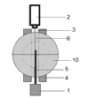
In first embodiment of probe of the present invention, be used for the transparent window (lighting window) of exciting light irradiation pipeline passway and be used for writing down radiative other transparent window (detection window) being in pipeline walls by detector.In this special embodiment (referring to Fig. 1), pipeline is with 90 ° angle bending.Lighting window is before a side of pipeline is in bending, and detection window is after this side of pipeline directly is in this bending, thereby detection window is open in the bottom of pipeline passway, and the detector recorded stream is to the fluid stream of said detector.This embodiment has special advantage: this stream is that the fixing angle of 0 degree is observed with relative flow direction, and each particle correspondingly surveyed as point, and prerequisite is that said particle moves perpendicular to exciting light during whole integral time point-blank.
In this embodiment of the present invention, advantageously, light volume maximum is the twice height of the field depth of detector, and typically, exciting light beam is collected on the thickness of 100 μ m to 10mm, preferred 150 μ m to 3mm.If measurement volumes is greater than field depth, then particles no longer is accurately measured.Iff requires once to survey incident, and then this measurement volumes should be only big as far as possible, so that collect light as much as possible.
Because the angle of pipeline also influences the direction of the fluid stream in the circuit before the bending, therefore advantageously, the structure of measuring unit is supported the not interrupted laminar flow in measurement volumes of particle point-blank, does not also promptly have dead space and under the constant speed situation.For this reason, can perhaps use different devices individually each other in combination.
For example preferably, glass pane is fixed in the pipeline walls with pipeline passway with flushing.The shape of window is arbitrarily, and normally diameter is 2 to 100mm circle.Instead, probe can be by sapphire or quartz glass manufacturing, and said probe is fixed on the pipeline place.
For the availability in plastics-production equipment, window must stand flowing at liquation under the pressure of 400 ℃ of temperature and 1 to 250 crust.Typically, window is made up of sapphire or quartz glass, because its special soundness preferably is made up of sapphire, has the thickness of 10mm and as for example as described in DE 102 01 541 A1, being shaped as taper.Through the pressure by glass-to-metal seal, window element can be fixed to (Fig. 3) in the pipeline walls with pipeline passway with flushing.
In addition, preferably,, be matched with the size (Fig. 4) of pipeline apart from d from the surface of the center of lighting window and detection window for the optimal flow of particle.According to application, in addition advantageously, be matched with the viscosity of flow velocity and the fluid of being studied, so that optimize the laminar flow in measured zone apart from d.
Also possible is, so constitutes detection window, makes that the dead space 90 ° of angles of pipeline is minimum.For this reason, the structure of detection window can be mated like example as shown in fig. 5ly.
In second embodiment of probe of the present invention, realize the orientation that corresponding light beam is necessary to each other by prism.So measuring unit has unique window usually, this window is inserted in pipeline walls and is had prism as glass pane (Fig. 5 and 6) in the edge of pipeline.Instead, the probe of being processed by sapphire or quartz glass can be manufactured to has suitable prismatic geometry, and said probe is fixed on the pipeline place.
This special embodiment has advantage: fluid stream can flow through this window in the clear.The location of light source, detector and the geometry of prism and optical characteristics are guaranteed the radiative relatively suitable vertical orientation of exciting light.On the fixing angle of preferred 45 ° or 135 ° of relative flow direction, observe.In this is implemented, particle as the line of aiming at by record.
In prism was implemented, the thickness of exciting light beam was preferably thin than pipeline diameter.Advantageously, be the thickness of 5mm, preferred 150 μ m to 3mm to the maximum, but it depends on the diameter of flow channel.For example be directed against the flow channel diameter of 5mm, the light beam thickness of preferred maximum 1mm.If measurement volumes is greater than field depth, then particles no longer is accurately measured.Iff need once be surveyed incident, and then this measurement volumes should be only big as far as possible, so that collect light as much as possible.
For described embodiment 1 and 2, maybe be advantageously, directly, constant thereby the temperature of the fluid that flows through can be held by the heating element measuring unit of heating.Typical heating element is through subsidiary heating of the oil of water back or electrical heating.
In the present invention, detector can be write down the light intensity by the emission of photism particle under 500 to 700nm wavelength situation usually.If write down the light intensity by the emission of light scattering property particle by this detector, then this usually occurs in the field wave strong point.In case of necessity, use the emission filtrator, so that optionally detect this wavelength coverage.
Also possible is, uses a plurality of detectors, wherein can be with the detector and the combinations of detectors (for example as shown in Figure 10) that is used to survey light scattering property particle that are used to survey the photism particle.
Possible detector for example is CCD camera, CMOS camera, amplifier camera, photomultiplier cell, photoelectric cell.Suitable camera is an enough light activated camera in probing wave scope (500-700nm).For example, use the camera Stingray (according to model, picture frequency is 9 to 84 fqs) of AVT company.The advantage of camera is, not only can detect the luminous intensity of particle and can detect the face of particle.
According to the present invention, light source perhaps shines the volume of sample of flow channel and the particle that stimulus stream is crossed continuously on integral time.
Usually, be matched with the size and the flow velocity of volume of sample integral time.
Detector writes down on integral time from the emission light of channel interior and with this information and is transmitted to image analyzing unit, and this image analyzing unit is the part of computing machine normally.
Iconographic analysis is typically carried out according to the diagram of Fig. 7, and data are assessed and exported.
Therefore other theme of the present invention is to be used for surveying the method at the photism particle and the optional light scattering property particle of the fluid that flows through probe of the present invention, has following step:
The height of-input light volume and input flow velocity and calculate integral time being used for controlling the element of integral time, wherein be that particle flows through the required time of light volume integral time under the flow condition of definition,
-through light source excitation light, be used to define the light volume,
-on integral time, survey emitted radiation by detector,
-analyze detection data by image analyzing unit,
The granule strength of-output amounts of particles and/or particle size distribution and/or every volume and/or every weight distributes and/or output photism agglomeration of particles image on the time of confirming.
Other theme of the present invention is to use probe of the present invention and/or the inventive method to be used for on-line monitoring production equipment, especially plastics-production equipment, cleaning equipment.
Fig. 1,3 to 6 illustrate the possible enforcement of present device, the invention is not restricted to this.
Fig. 2 and 7 or 11 shows the flow process of the flow process of invention method and the graphical analysis in image analyzing unit, but it is not limited thereto.
If can document image on integral time series, then can continue this analysis with image addition and according to Fig. 7 before the graphical analysis in image analyzing unit.In this case, image is by the image of addition.
Instead, image analyzing unit can come the carries out image analysis according to Figure 11, and in the scope of graphical analysis, carries out addition.
Description of drawings
Fig. 1 shows the probe of the present invention by embodiment 1;
Fig. 2 shows method figure;
Fig. 3 shows embodiment 1;
Fig. 4 shows under embodiment 1 situation the optimization apart from d;
Fig. 5 shows the window modification of embodiment 1;
Fig. 6 a shows the side view of the embodiment 2 with prism;
Fig. 6 b show embodiment 2 with prism from top view;
Fig. 7 shows the diagram of the graphical analysis in the image analyzing unit in this embodiment, is wherein equaling continuous recording particle on the longer detection time of integral time;
Fig. 8 shows the output of quantity of the fluorescing property particle of every gram liquation on this time;
Fig. 9 shows fluorescing property agglomeration of particles image on 6 hours;
Figure 10 shows the probe that is used for surveying simultaneously photism particle and light scattering property particle;
Figure 11 shows the diagram of the graphical analysis in image analyzing unit in this embodiment, wherein document image series on integral time.
Reference numeral:
1 light source
2 detectors
2a is used to survey the detector of photism particle
2b is used to survey the detector of light scattering property particle
3 pipeline passways
4 pipeline walls
5 exciting light beams
6 emission light
7 glass panes
8 glass-to-metal seals
9 apertures
10 prisms
11 dichronic mirror 530nm
12 excitation filtrator 400-500nm
13 fluorescence filter 550-650nm.
Example:
The pipeline of pipeline passway with 8mm diameter is with 90 ° of angle bendings.
In pipeline walls; In a side of pipeline at milling lighting window before this bending and at the direct milling detection window after this bending of this side of pipeline, thereby this detection window be open in the bottom of pipeline passway and this detector can recorded stream to the fluid stream of this detector.
Is 14mm from the surface of the center of lighting window and detection window apart from d.
These windows both is the circle with 9mm diameter.In each window, through pressure by glass-to-metal seal flush with pipeline passway the glass pane of processing by sapphire (Fig. 3) that is shaped of the taper that fixedly 10mm is thick.
Probe is loaded in the pipeline of polycarbonate equipment, wherein the polycarbonate liquation under 300 ℃ temperature with the flow rate of 6m/min.
Before lighting window, with excitation filtrator (HQ450/100 M-2P LOT Oriel) and aperture combination fix commercial available xenon lamp (Drelloscop 255, Drello company).The excitation wavelength of light beam is adjusted on the 400-500nm by the excitation filtrator.This light beam is focused on the mean diameter of 2mm by the aperture.
Before detection window; With emission filtrator (HQ600/100M-2P of LOT Oriel company) and beam splitter (530DCXRU of LOT Oriel company) fixed camera (the Stingray F-033B of AVT company in combination; Until 58 fps), be used for being chosen in 550 to 650nm wavelength coverage record.This camera perpendicular to exciting light be fixed, make this camera can write down the whole diameter of pipeline passway.
The interface of this camera and the element that is used to control integral time and with image analyzing unit, be that two elements of computing machine are connected.
At the element that is used for controlling integral time, the height (2mm) and the flow velocity of input volume of sample.Calculated the integral time of 20ms.Light source is this volume of sample of Continuous irradiation under 400-500nm wavelength situation.
Camera 550 to 650nm survey in the wavelength coverages record volume of sample on the integral time of the element control through being used to control integral time image.
Recorded data is transferred in the image analyzing unit and by image analyzing unit by camera and handles according to Fig. 7.
Fig. 8 and 9 shows output possible after deal with data.
Claims (15)
1. be used for surveying at the photism particle of flowing fluid and the probe of optional light scattering property particle, this probe has the measuring unit that comprises following element:
-pipeline passway that fluid to be measured flows through,
-at least one transparent window in the wall of pipeline,
-at least one is used to produce the light source of the exciting light beam that size confirms, and said exciting light beam is activated at photism particle and light scattering property particle in the pipeline passway through said window in the restricted smooth volume of optics,
-at least one detector, said detector is through said window or pass through the electromagnetic radiation that another window writes down photism particle and optional light scattering property particle,
-being used to control the element of integral time, the height that said element is used to import volume of sample and input flow velocity and calculating and control integral time, wherein be that particle flows through the required time of light volume integral time under the flow condition of input,
Wherein in measuring unit, the exciting light beam that size is confirmed and directed mutual vertically by the light of photism and/or the emission of light scattering property particle,
Wherein each particle is parallel to fluid stream motion in measurement volumes, and fluid stream is with the fixing flows at angles of relative exciting light,
Wherein fluid stream, detector and light source be in the plane and
Wherein detector has to the interface of the element that is used to control integral time, makes detector can on the integral time of being calculated, write down the light of being launched by the photism particle.
2. probe according to claim 1 is characterized in that, the fixing angle of the relative exciting light of grain flow is in the scope of 45 to 135 degree.
3. according to the described probe of one of claim 1 to 2, it is characterized in that exciting light beam is injected on the whole pipeline diameter of pipeline passway.
4. according to the described probe of one of claim 1 to 3; It is characterized in that; Pipeline is with 90 ° of angle bendings, and said pipeline had the transparent lighting window that is used to shine pipeline passway in a side before bending, and directly after this bending, has in this side of this pipeline and to be used for writing down radiative transparent detection window by detector; Thereby detection window is open in the bottom of pipeline passway, and the detector recorded stream is to the fluid stream of said detector.
5. probe according to claim 4 is characterized in that, for flowing of the best of particle, is matched with the size of pipeline from the surface of the center of lighting window and detection window apart from d.
6. according to the described probe in one of claim 4 or 5, it is characterized in that the light volume maximum just in time twice field depth with object lens is the same high.
7. according to the described probe of one of claim 1 to 3; It is characterized in that; Measuring unit has unique window, and said window is inserted in pipeline walls and had prism as glass pane in the edge of pipeline, and it guarantees the radiative relatively vertical orientation of exciting light.
8. probe according to claim 7 is characterized in that the thickness of exciting light beam is 5mm to the maximum.
9. according to the described probe of one of claim 1 to 8, it is characterized in that said probe has detector that is used for the photism particle and the detector that is used for the scattered light particle.
10. be used for surveying and flowing through, have following step according to the photism particle of the fluid of the described probe of one of claim 1 to 9 and the method for optional light scattering property particle:
A. height and the input of importing the light volume in pipeline flow velocity and calculate integral time being used for controlling the element of integral time, wherein be that particle flows through the required time of light volume integral time under the flow condition of definition,
B. through light source exciting light on whole pipeline diameter, be used to define the light volume,
C. emission light is being surveyed on whole pipeline diameter by detector on integral time,
D. analyze detection data by image analyzing unit,
E. the granule strength of exporting amounts of particles and/or particle size distribution and/or every volume and/or every weight distributes and/or output photism or light scattering property agglomeration of particles image on the time of confirming.
11. method according to claim 10 is wherein carried out on whole pipeline diameter in light stimulus on the whole pipeline diameter and emission photodetection.
12. according to the described method of one of claim 11 to 12, wherein detector is high-resolution light activated camera.
13. method according to claim 13 wherein writes down particle on long detection time.
14. method according to claim 13, detector document image series on integral time wherein, said image sequence on this time by addition.
15. be used for the application of on-line monitoring production equipment, especially plastics-production equipment or cleaning equipment according to the described probe of one of claim 1 to 9 or according to the described method of one of claim 11 to 14.
Applications Claiming Priority (3)
| Application Number | Priority Date | Filing Date | Title |
|---|---|---|---|
| EP09015341A EP2333515A1 (en) | 2009-12-11 | 2009-12-11 | Device for detecting luminous and/or light-diffusing particles in flowing liquids |
| EP09015341.2 | 2009-12-11 | ||
| PCT/EP2010/068998 WO2011069976A1 (en) | 2009-12-11 | 2010-12-06 | Means for detecting luminescent and/or light-scattering particles in flowing liquids |
Publications (1)
| Publication Number | Publication Date |
|---|---|
| CN102652257A true CN102652257A (en) | 2012-08-29 |
Family
ID=42077159
Family Applications (1)
| Application Number | Title | Priority Date | Filing Date |
|---|---|---|---|
| CN2010800561275A Pending CN102652257A (en) | 2009-12-11 | 2010-12-06 | Means for detecting luminescent and/or light-scattering particles in flowing liquids |
Country Status (11)
| Country | Link |
|---|---|
| US (1) | US20120281203A1 (en) |
| EP (2) | EP2333515A1 (en) |
| JP (1) | JP2013513789A (en) |
| KR (1) | KR20120092188A (en) |
| CN (1) | CN102652257A (en) |
| AU (1) | AU2010329979A1 (en) |
| CA (1) | CA2783989A1 (en) |
| IN (1) | IN2012DN05124A (en) |
| SG (1) | SG181139A1 (en) |
| TW (1) | TW201135210A (en) |
| WO (1) | WO2011069976A1 (en) |
Cited By (12)
| Publication number | Priority date | Publication date | Assignee | Title |
|---|---|---|---|---|
| CN104931465A (en) * | 2014-03-21 | 2015-09-23 | 中国石油化工股份有限公司 | Apparatus for monitoring dissolving states of oil, gas and water in dissolving kettle, and method thereof |
| CN105136673A (en) * | 2014-05-30 | 2015-12-09 | 阿自倍尔株式会社 | Device for detecting particles in a liquid and method for detecting particles in a liquid |
| CN105264355A (en) * | 2013-05-21 | 2016-01-20 | 圣瑞克斯公司 | Fluid diagnostic devices and methods of using the same |
| CN105324662A (en) * | 2013-04-02 | 2016-02-10 | Btg仪器公司 | A method for determining a property of a heterogeneous medium |
| CN105408734A (en) * | 2013-06-24 | 2016-03-16 | 西门子公司 | Particle detector and method for detecting particles |
| CN107091796A (en) * | 2017-06-14 | 2017-08-25 | 中央民族大学 | The optical system that across particle diameter size granule level is matched somebody with somebody and its is distributed in a kind of measurement pipe stream |
| CN107677686A (en) * | 2017-09-28 | 2018-02-09 | 京东方科技集团股份有限公司 | Equipment of the light through window integrating device and using the device |
| CN108414480A (en) * | 2018-01-26 | 2018-08-17 | 中国海洋石油集团有限公司 | A kind of crude oil fluorescence measuring device and method |
| CN111273054A (en) * | 2018-12-05 | 2020-06-12 | 西卡西伯特博士及屈恩有限及两合公司 | Flow measuring method and flow measuring device for optical flow measurement |
| CN111323360A (en) * | 2018-12-14 | 2020-06-23 | 中国科学院深圳先进技术研究院 | Image acquisition equipment and detection device for particles in liquid |
| CN113015897A (en) * | 2018-11-16 | 2021-06-22 | 粒子监测系统有限公司 | Slurry monitoring and single particle detection in combination with bulk size distribution |
| CN113167682A (en) * | 2018-12-13 | 2021-07-23 | 罗伯特·博世有限公司 | Method, computer program and electronic storage medium for detecting particles or aerosols in a flowing fluid |
Families Citing this family (8)
| Publication number | Priority date | Publication date | Assignee | Title |
|---|---|---|---|---|
| NL2010538C2 (en) * | 2013-03-28 | 2014-09-30 | Ihc Syst Bv | Measurement device for performing measurement on a mixture of water and collected material. |
| CN105181374A (en) * | 2015-10-09 | 2015-12-23 | 绍兴文理学院 | Boiler flue gas tourmalinite purifier scattering online test board |
| US11187661B2 (en) | 2017-07-05 | 2021-11-30 | Saudi Arabian Oil Company | Detecting black powder levels in flow-lines |
| US10983044B2 (en) | 2018-06-26 | 2021-04-20 | Arometrix, Inc. | Device, system and method for in-situ optical monitoring and control of extraction and purification of plant materials |
| CN109084683B (en) * | 2018-10-19 | 2023-11-28 | 广东中道创意科技有限公司 | Particulate matter detection device |
| KR102098701B1 (en) * | 2019-03-12 | 2020-04-08 | 주식회사 지씨에스월드 | Apparatus for detecting dust and analyzing shape thereof in liquid using image sensor and method thereof |
| US11441992B2 (en) * | 2020-05-27 | 2022-09-13 | Applied Materials, Inc. | Method and apparatus for detection of particle size in a fluid |
| CN113959947A (en) * | 2021-10-25 | 2022-01-21 | 山东大学 | Single-particle multi-modal flow imaging detection device and method based on two-dimensional light scattering |
Citations (3)
| Publication number | Priority date | Publication date | Assignee | Title |
|---|---|---|---|---|
| US6309886B1 (en) * | 1999-06-04 | 2001-10-30 | The Regents Of The University Of California | High throughput analysis of samples in flowing liquid |
| CN101278829A (en) * | 2008-05-26 | 2008-10-08 | 上海理工大学 | Portable in vivo flow cytometry |
| JP2009258071A (en) * | 2008-03-28 | 2009-11-05 | Fujifilm Corp | Particle analyzer and particle analysis method |
Family Cites Families (14)
| Publication number | Priority date | Publication date | Assignee | Title |
|---|---|---|---|---|
| DK66992D0 (en) * | 1992-05-21 | 1992-05-21 | Faxe Kalkbrud Aktieselskabet | SENSOR |
| US5489977A (en) * | 1993-08-11 | 1996-02-06 | Texaco Inc. | Photomeric means for monitoring solids and fluorescent material in waste water using a falling stream water sampler |
| JP3124989B2 (en) * | 1994-12-19 | 2001-01-15 | リオン株式会社 | Light scattering particle detector |
| US5608517A (en) * | 1995-02-28 | 1997-03-04 | Thermo Separation Products Inc. | Flow cell and method for making same |
| JPH10115584A (en) * | 1996-10-11 | 1998-05-06 | Dkk Corp | Fluorescent flow cell |
| US6473176B2 (en) * | 1999-01-25 | 2002-10-29 | Amnis Corporation | Imaging and analyzing parameters of small moving objects such as cells |
| US7280207B2 (en) * | 2001-07-25 | 2007-10-09 | Applera Corporation | Time-delay integration in a flow cytometry system |
| US6809810B2 (en) * | 2001-10-04 | 2004-10-26 | Applera Corporation | Detection cell |
| DE10201541A1 (en) | 2002-01-17 | 2003-08-14 | Bayer Ag | Exchangeable process window |
| JP4365258B2 (en) * | 2004-04-13 | 2009-11-18 | 三機工業株式会社 | Drainage pollution concentration detection system, drainage pollution detection device, and drainage pollution detection piping unit |
| DE102005021179A1 (en) * | 2005-05-06 | 2006-11-09 | Lt-Research Gmbh | Evaluating signal from light detector in focussed beam reflectance measuring device, by using state machine and increasing secant length while logical one exists at output of detections stage |
| DE102005028893B4 (en) | 2005-06-19 | 2007-12-06 | Stiftung Alfred-Wegener-Institut für Polar- und Meeresforschung Stiftung des öffentlichen Rechts | Device for particle detection in a depth-limited lens |
| JP4468875B2 (en) * | 2005-09-02 | 2010-05-26 | 日本電信電話株式会社 | Prism / liquid reservoir integrated chip for surface plasmon resonance spectrum measurement, manufacturing method thereof, and surface plasmon resonance measurement apparatus using the same |
| US7565042B2 (en) * | 2005-10-03 | 2009-07-21 | Creatv Microtech, Inc. | Sensitive emission light gathering and flow through detection system |
-
2009
- 2009-12-11 EP EP09015341A patent/EP2333515A1/en not_active Withdrawn
-
2010
- 2010-12-06 US US13/514,914 patent/US20120281203A1/en not_active Abandoned
- 2010-12-06 EP EP10790917A patent/EP2510333A1/en not_active Withdrawn
- 2010-12-06 SG SG2012039756A patent/SG181139A1/en unknown
- 2010-12-06 KR KR1020127017866A patent/KR20120092188A/en not_active Application Discontinuation
- 2010-12-06 JP JP2012542498A patent/JP2013513789A/en active Pending
- 2010-12-06 WO PCT/EP2010/068998 patent/WO2011069976A1/en active Application Filing
- 2010-12-06 CN CN2010800561275A patent/CN102652257A/en active Pending
- 2010-12-06 CA CA2783989A patent/CA2783989A1/en not_active Abandoned
- 2010-12-06 AU AU2010329979A patent/AU2010329979A1/en not_active Abandoned
- 2010-12-10 TW TW099143147A patent/TW201135210A/en unknown
-
2012
- 2012-06-11 IN IN5124DEN2012 patent/IN2012DN05124A/en unknown
Patent Citations (3)
| Publication number | Priority date | Publication date | Assignee | Title |
|---|---|---|---|---|
| US6309886B1 (en) * | 1999-06-04 | 2001-10-30 | The Regents Of The University Of California | High throughput analysis of samples in flowing liquid |
| JP2009258071A (en) * | 2008-03-28 | 2009-11-05 | Fujifilm Corp | Particle analyzer and particle analysis method |
| CN101278829A (en) * | 2008-05-26 | 2008-10-08 | 上海理工大学 | Portable in vivo flow cytometry |
Cited By (16)
| Publication number | Priority date | Publication date | Assignee | Title |
|---|---|---|---|---|
| CN105324662A (en) * | 2013-04-02 | 2016-02-10 | Btg仪器公司 | A method for determining a property of a heterogeneous medium |
| CN105264355B (en) * | 2013-05-21 | 2018-10-30 | 圣瑞克斯公司 | Fluid diagnostic device and its application method |
| CN105264355A (en) * | 2013-05-21 | 2016-01-20 | 圣瑞克斯公司 | Fluid diagnostic devices and methods of using the same |
| CN105408734A (en) * | 2013-06-24 | 2016-03-16 | 西门子公司 | Particle detector and method for detecting particles |
| CN104931465A (en) * | 2014-03-21 | 2015-09-23 | 中国石油化工股份有限公司 | Apparatus for monitoring dissolving states of oil, gas and water in dissolving kettle, and method thereof |
| CN104931465B (en) * | 2014-03-21 | 2018-02-09 | 中国石油化工股份有限公司 | For the device and method for the dissolved state for monitoring the oil gas water in dissolution kettle |
| CN105136673A (en) * | 2014-05-30 | 2015-12-09 | 阿自倍尔株式会社 | Device for detecting particles in a liquid and method for detecting particles in a liquid |
| CN107091796A (en) * | 2017-06-14 | 2017-08-25 | 中央民族大学 | The optical system that across particle diameter size granule level is matched somebody with somebody and its is distributed in a kind of measurement pipe stream |
| CN107677686B (en) * | 2017-09-28 | 2021-01-26 | 京东方科技集团股份有限公司 | Light transmission window integrated device and equipment adopting same |
| CN107677686A (en) * | 2017-09-28 | 2018-02-09 | 京东方科技集团股份有限公司 | Equipment of the light through window integrating device and using the device |
| CN108414480A (en) * | 2018-01-26 | 2018-08-17 | 中国海洋石油集团有限公司 | A kind of crude oil fluorescence measuring device and method |
| CN113015897A (en) * | 2018-11-16 | 2021-06-22 | 粒子监测系统有限公司 | Slurry monitoring and single particle detection in combination with bulk size distribution |
| CN111273054A (en) * | 2018-12-05 | 2020-06-12 | 西卡西伯特博士及屈恩有限及两合公司 | Flow measuring method and flow measuring device for optical flow measurement |
| CN113167682A (en) * | 2018-12-13 | 2021-07-23 | 罗伯特·博世有限公司 | Method, computer program and electronic storage medium for detecting particles or aerosols in a flowing fluid |
| CN111323360A (en) * | 2018-12-14 | 2020-06-23 | 中国科学院深圳先进技术研究院 | Image acquisition equipment and detection device for particles in liquid |
| CN111323360B (en) * | 2018-12-14 | 2022-07-05 | 中国科学院深圳先进技术研究院 | Image acquisition equipment and detection device for particles in liquid |
Also Published As
| Publication number | Publication date |
|---|---|
| EP2510333A1 (en) | 2012-10-17 |
| US20120281203A1 (en) | 2012-11-08 |
| KR20120092188A (en) | 2012-08-20 |
| TW201135210A (en) | 2011-10-16 |
| SG181139A1 (en) | 2012-07-30 |
| CA2783989A1 (en) | 2011-06-16 |
| IN2012DN05124A (en) | 2015-10-23 |
| JP2013513789A (en) | 2013-04-22 |
| EP2333515A1 (en) | 2011-06-15 |
| AU2010329979A1 (en) | 2012-07-05 |
| WO2011069976A1 (en) | 2011-06-16 |
Similar Documents
| Publication | Publication Date | Title |
|---|---|---|
| CN102652257A (en) | Means for detecting luminescent and/or light-scattering particles in flowing liquids | |
| JP5787390B2 (en) | Microorganism detection apparatus and method | |
| CN104919035B (en) | Portable fluorescence detecting system and micro- determination box | |
| EP3382371A1 (en) | Aerosol real time monitor | |
| US8681215B2 (en) | Method and particle analyzer for determining a broad particle size distribution | |
| CN107783242B (en) | Automatic focusing device and block LIBS online detection device adopting same | |
| KR101623787B1 (en) | Portable real-time detecting device for biological aerosol | |
| EP1726940A1 (en) | Light measurement apparatus and light measurement method | |
| WO2017060105A1 (en) | Particle sensor for particle detection | |
| JP6513802B2 (en) | Laser light coupling for nanoparticle detection | |
| EP2526401A1 (en) | Flow cytometry analysis across optical fiber | |
| CN104931474B (en) | The online laser detector of cement slurry quality and method | |
| CN101796391A (en) | Blood examination apparatus | |
| WO2017067971A1 (en) | Measurement cell for saxs measurements and for dls measurements | |
| CN106066320B (en) | Seawater bacteria detection system based on multi-wavelength laser induced bacteria intrinsic fluorescence | |
| US10386284B2 (en) | Device and method for measurement of dispersed objects using fluorescent and non-fluorescent imaging with laser | |
| WO2017060164A1 (en) | Optical sensor for particle detection | |
| CN110554009A (en) | Magnetic powder inspection fluorescence imaging device for detecting steel profiled parts | |
| JP2013526714A (en) | Configuration for measuring the optical properties of dispersed particles | |
| US20220268753A1 (en) | Systems, subsystems and methods for measuring water characteristics in a water facility | |
| EP4040138B1 (en) | Use of a particle measuring device | |
| KR101177285B1 (en) | Fluorescence Measurement Cell Improved By Laser Multi-Reflection For On-Line Monitoring Of Process Materials In High Temperature Molten Salt | |
| CN110554085A (en) | Integrated camera assembly for detecting magnetic powder inspection fluorescence imaging of small-sized special-shaped piece | |
| CN111122527A (en) | In-situ microscopic imaging detection device and detection method for bacteria in water environment | |
| JP2017207336A (en) | Particle detection device and inspection method thereof |
Legal Events
| Date | Code | Title | Description |
|---|---|---|---|
| C06 | Publication | ||
| PB01 | Publication | ||
| ASS | Succession or assignment of patent right |
Owner name: BAYER INTELLECTUAL PROPERTY GMBH Free format text: FORMER OWNER: BAYER AG Effective date: 20120827 |
|
| C41 | Transfer of patent application or patent right or utility model | ||
| TA01 | Transfer of patent application right |
Effective date of registration: 20120827 Address after: German Monheim Applicant after: Bayer Pharma Aktiengesellschaft Address before: Germany Leverkusen Applicant before: Bayer Ag |
|
| C10 | Entry into substantive examination | ||
| SE01 | Entry into force of request for substantive examination | ||
| C02 | Deemed withdrawal of patent application after publication (patent law 2001) | ||
| WD01 | Invention patent application deemed withdrawn after publication |
Application publication date: 20120829 |