EP3663243B1 - Procédé et dispositif d'épissure d'un premier et d'un deuxième films composites - Google Patents
Procédé et dispositif d'épissure d'un premier et d'un deuxième films composites Download PDFInfo
- Publication number
- EP3663243B1 EP3663243B1 EP19212787.6A EP19212787A EP3663243B1 EP 3663243 B1 EP3663243 B1 EP 3663243B1 EP 19212787 A EP19212787 A EP 19212787A EP 3663243 B1 EP3663243 B1 EP 3663243B1
- Authority
- EP
- European Patent Office
- Prior art keywords
- clamping
- film
- composite
- film composite
- splicing
- Prior art date
- Legal status (The legal status is an assumption and is not a legal conclusion. Google has not performed a legal analysis and makes no representation as to the accuracy of the status listed.)
- Active
Links
Images

Classifications
-
- B—PERFORMING OPERATIONS; TRANSPORTING
- B65—CONVEYING; PACKING; STORING; HANDLING THIN OR FILAMENTARY MATERIAL
- B65H—HANDLING THIN OR FILAMENTARY MATERIAL, e.g. SHEETS, WEBS, CABLES
- B65H19/00—Changing the web roll
- B65H19/10—Changing the web roll in unwinding mechanisms or in connection with unwinding operations
- B65H19/18—Attaching, e.g. pasting, the replacement web to the expiring web
- B65H19/1805—Flying splicing, i.e. the expiring web moving during splicing contact
- B65H19/1826—Flying splicing, i.e. the expiring web moving during splicing contact taking place at a distance from the replacement roll
- B65H19/1831—Flying splicing, i.e. the expiring web moving during splicing contact taking place at a distance from the replacement roll the replacement web being stationary prior to splicing contact
-
- B—PERFORMING OPERATIONS; TRANSPORTING
- B29—WORKING OF PLASTICS; WORKING OF SUBSTANCES IN A PLASTIC STATE IN GENERAL
- B29C—SHAPING OR JOINING OF PLASTICS; SHAPING OF MATERIAL IN A PLASTIC STATE, NOT OTHERWISE PROVIDED FOR; AFTER-TREATMENT OF THE SHAPED PRODUCTS, e.g. REPAIRING
- B29C65/00—Joining or sealing of preformed parts, e.g. welding of plastics materials; Apparatus therefor
- B29C65/48—Joining or sealing of preformed parts, e.g. welding of plastics materials; Apparatus therefor using adhesives, i.e. using supplementary joining material; solvent bonding
- B29C65/50—Joining or sealing of preformed parts, e.g. welding of plastics materials; Apparatus therefor using adhesives, i.e. using supplementary joining material; solvent bonding using adhesive tape, e.g. thermoplastic tape; using threads or the like
- B29C65/5042—Joining or sealing of preformed parts, e.g. welding of plastics materials; Apparatus therefor using adhesives, i.e. using supplementary joining material; solvent bonding using adhesive tape, e.g. thermoplastic tape; using threads or the like covering both elements to be joined
-
- B—PERFORMING OPERATIONS; TRANSPORTING
- B29—WORKING OF PLASTICS; WORKING OF SUBSTANCES IN A PLASTIC STATE IN GENERAL
- B29C—SHAPING OR JOINING OF PLASTICS; SHAPING OF MATERIAL IN A PLASTIC STATE, NOT OTHERWISE PROVIDED FOR; AFTER-TREATMENT OF THE SHAPED PRODUCTS, e.g. REPAIRING
- B29C65/00—Joining or sealing of preformed parts, e.g. welding of plastics materials; Apparatus therefor
- B29C65/78—Means for handling the parts to be joined, e.g. for making containers or hollow articles, e.g. means for handling sheets, plates, web-like materials, tubular articles, hollow articles or elements to be joined therewith; Means for discharging the joined articles from the joining apparatus
- B29C65/7858—Means for handling the parts to be joined, e.g. for making containers or hollow articles, e.g. means for handling sheets, plates, web-like materials, tubular articles, hollow articles or elements to be joined therewith; Means for discharging the joined articles from the joining apparatus characterised by the feeding movement of the parts to be joined
- B29C65/7888—Means for handling of moving sheets or webs
- B29C65/7894—Means for handling of moving sheets or webs of continuously moving sheets or webs
-
- B—PERFORMING OPERATIONS; TRANSPORTING
- B29—WORKING OF PLASTICS; WORKING OF SUBSTANCES IN A PLASTIC STATE IN GENERAL
- B29C—SHAPING OR JOINING OF PLASTICS; SHAPING OF MATERIAL IN A PLASTIC STATE, NOT OTHERWISE PROVIDED FOR; AFTER-TREATMENT OF THE SHAPED PRODUCTS, e.g. REPAIRING
- B29C66/00—General aspects of processes or apparatus for joining preformed parts
- B29C66/01—General aspects dealing with the joint area or with the area to be joined
- B29C66/05—Particular design of joint configurations
- B29C66/10—Particular design of joint configurations particular design of the joint cross-sections
- B29C66/11—Joint cross-sections comprising a single joint-segment, i.e. one of the parts to be joined comprising a single joint-segment in the joint cross-section
- B29C66/114—Single butt joints
- B29C66/1142—Single butt to butt joints
-
- B—PERFORMING OPERATIONS; TRANSPORTING
- B29—WORKING OF PLASTICS; WORKING OF SUBSTANCES IN A PLASTIC STATE IN GENERAL
- B29C—SHAPING OR JOINING OF PLASTICS; SHAPING OF MATERIAL IN A PLASTIC STATE, NOT OTHERWISE PROVIDED FOR; AFTER-TREATMENT OF THE SHAPED PRODUCTS, e.g. REPAIRING
- B29C66/00—General aspects of processes or apparatus for joining preformed parts
- B29C66/40—General aspects of joining substantially flat articles, e.g. plates, sheets or web-like materials; Making flat seams in tubular or hollow articles; Joining single elements to substantially flat surfaces
- B29C66/41—Joining substantially flat articles ; Making flat seams in tubular or hollow articles
- B29C66/43—Joining a relatively small portion of the surface of said articles
-
- B—PERFORMING OPERATIONS; TRANSPORTING
- B29—WORKING OF PLASTICS; WORKING OF SUBSTANCES IN A PLASTIC STATE IN GENERAL
- B29C—SHAPING OR JOINING OF PLASTICS; SHAPING OF MATERIAL IN A PLASTIC STATE, NOT OTHERWISE PROVIDED FOR; AFTER-TREATMENT OF THE SHAPED PRODUCTS, e.g. REPAIRING
- B29C66/00—General aspects of processes or apparatus for joining preformed parts
- B29C66/70—General aspects of processes or apparatus for joining preformed parts characterised by the composition, physical properties or the structure of the material of the parts to be joined; Joining with non-plastics material
- B29C66/72—General aspects of processes or apparatus for joining preformed parts characterised by the composition, physical properties or the structure of the material of the parts to be joined; Joining with non-plastics material characterised by the structure of the material of the parts to be joined
- B29C66/723—General aspects of processes or apparatus for joining preformed parts characterised by the composition, physical properties or the structure of the material of the parts to be joined; Joining with non-plastics material characterised by the structure of the material of the parts to be joined being multi-layered
-
- B—PERFORMING OPERATIONS; TRANSPORTING
- B29—WORKING OF PLASTICS; WORKING OF SUBSTANCES IN A PLASTIC STATE IN GENERAL
- B29C—SHAPING OR JOINING OF PLASTICS; SHAPING OF MATERIAL IN A PLASTIC STATE, NOT OTHERWISE PROVIDED FOR; AFTER-TREATMENT OF THE SHAPED PRODUCTS, e.g. REPAIRING
- B29C66/00—General aspects of processes or apparatus for joining preformed parts
- B29C66/80—General aspects of machine operations or constructions and parts thereof
- B29C66/83—General aspects of machine operations or constructions and parts thereof characterised by the movement of the joining or pressing tools
- B29C66/834—General aspects of machine operations or constructions and parts thereof characterised by the movement of the joining or pressing tools moving with the parts to be joined
- B29C66/8351—Jaws mounted on rollers, cylinders, drums, bands, belts or chains; Flying jaws
- B29C66/83511—Jaws mounted on rollers, cylinders, drums, bands, belts or chains; Flying jaws jaws mounted on rollers, cylinders or drums
- B29C66/83513—Jaws mounted on rollers, cylinders, drums, bands, belts or chains; Flying jaws jaws mounted on rollers, cylinders or drums cooperating jaws mounted on rollers, cylinders or drums and moving in a closed path
-
- B—PERFORMING OPERATIONS; TRANSPORTING
- B29—WORKING OF PLASTICS; WORKING OF SUBSTANCES IN A PLASTIC STATE IN GENERAL
- B29C—SHAPING OR JOINING OF PLASTICS; SHAPING OF MATERIAL IN A PLASTIC STATE, NOT OTHERWISE PROVIDED FOR; AFTER-TREATMENT OF THE SHAPED PRODUCTS, e.g. REPAIRING
- B29C66/00—General aspects of processes or apparatus for joining preformed parts
- B29C66/80—General aspects of machine operations or constructions and parts thereof
- B29C66/84—Specific machine types or machines suitable for specific applications
- B29C66/853—Machines for changing web rolls or filaments, e.g. for joining a replacement web to an expiring web
-
- B—PERFORMING OPERATIONS; TRANSPORTING
- B65—CONVEYING; PACKING; STORING; HANDLING THIN OR FILAMENTARY MATERIAL
- B65H—HANDLING THIN OR FILAMENTARY MATERIAL, e.g. SHEETS, WEBS, CABLES
- B65H2301/00—Handling processes for sheets or webs
- B65H2301/40—Type of handling process
- B65H2301/46—Splicing
- B65H2301/462—Form of splice
- B65H2301/4622—Abutting article or web portions, i.e. edge to edge
- B65H2301/46222—Abutting article or web portions, i.e. edge to edge involving double butt splice, i.e. adhesive tape applied on both sides of the article or web portions
-
- B—PERFORMING OPERATIONS; TRANSPORTING
- B65—CONVEYING; PACKING; STORING; HANDLING THIN OR FILAMENTARY MATERIAL
- B65H—HANDLING THIN OR FILAMENTARY MATERIAL, e.g. SHEETS, WEBS, CABLES
- B65H2301/00—Handling processes for sheets or webs
- B65H2301/40—Type of handling process
- B65H2301/46—Splicing
- B65H2301/463—Splicing splicing means, i.e. means by which a web end is bound to another web end
- B65H2301/4631—Adhesive tape
-
- B—PERFORMING OPERATIONS; TRANSPORTING
- B65—CONVEYING; PACKING; STORING; HANDLING THIN OR FILAMENTARY MATERIAL
- B65H—HANDLING THIN OR FILAMENTARY MATERIAL, e.g. SHEETS, WEBS, CABLES
- B65H2301/00—Handling processes for sheets or webs
- B65H2301/40—Type of handling process
- B65H2301/46—Splicing
- B65H2301/464—Splicing effecting splice
- B65H2301/46414—Splicing effecting splice by nipping rollers
-
- B—PERFORMING OPERATIONS; TRANSPORTING
- B65—CONVEYING; PACKING; STORING; HANDLING THIN OR FILAMENTARY MATERIAL
- B65H—HANDLING THIN OR FILAMENTARY MATERIAL, e.g. SHEETS, WEBS, CABLES
- B65H2406/00—Means using fluid
- B65H2406/30—Suction means
- B65H2406/33—Rotary suction means, e.g. roller, cylinder or drum
-
- B—PERFORMING OPERATIONS; TRANSPORTING
- B65—CONVEYING; PACKING; STORING; HANDLING THIN OR FILAMENTARY MATERIAL
- B65H—HANDLING THIN OR FILAMENTARY MATERIAL, e.g. SHEETS, WEBS, CABLES
- B65H2406/00—Means using fluid
- B65H2406/30—Suction means
- B65H2406/35—Other elements with suction surface, e.g. plate or wall
- B65H2406/351—Other elements with suction surface, e.g. plate or wall facing the surface of the handled material
-
- B—PERFORMING OPERATIONS; TRANSPORTING
- B65—CONVEYING; PACKING; STORING; HANDLING THIN OR FILAMENTARY MATERIAL
- B65H—HANDLING THIN OR FILAMENTARY MATERIAL, e.g. SHEETS, WEBS, CABLES
- B65H2701/00—Handled material; Storage means
- B65H2701/10—Handled articles or webs
- B65H2701/17—Nature of material
- B65H2701/172—Composite material
Definitions
- the invention relates to a method and a device for splicing one end of a first composite film to a beginning of a second composite film.
- the first and second film composite are cut end to end, with the end of the first film composite and the beginning of the second film composite being fed to a connecting station at the same time, in which a first connecting element is applied to the joint with a roller. Subsequently, another opposing joining element is applied to the joint with an opposing roller in the joining station.
- a splicing device which is provided for splicing one end of a first composite film to a beginning of a second composite film.
- a joint is cut in a first pair of rollers and a connecting element is applied to one side of this joint and then another connecting element is applied to the joint on another pair of rollers arranged separately therefrom on the opposite side.
- a method of a device for producing a film composite in which the film composite comprises at least one polymer layer that is processed, in particular provided with a hologram.
- a first and a second supply roll for the film composite are provided, which are successively fed to a splicing device. If the first supply roll is used up, the second supply roll is used.
- a butt-to-butt joint is created from the end of the composite film from the first supply roll to the beginning of the second composite film from the second supply roll. During the creation of this butt-to-butt joint, there is a brief standstill. Since the film composite is processed continuously, the splicing device is followed by a storage station, so that during the short-term standstill of the splicing device, the subsequent processing stations are continuously supplied with the film composite from the storage device.
- the invention has for its object to propose a method and a device for splicing one end of a first film composite with a beginning of the second film composite, whereby a It is possible to change the supply rolls from a first film composite to a second film composite without stopping subsequent processing stations.
- This object is achieved by a method for splicing one end of the first film composite to the beginning of the second film composite in a splicing device with the following steps.
- the first composite film is guided through the splicing device.
- the beginning of the second composite film is fed to the splicing device.
- the first composite film and the second composite film are cut to butt.
- the joint formed by the end of the first composite film and the beginning of the second composite film are fed together to a connecting station.
- a connecting element is applied to one or both sides of an outer side of the first and second film composite and covers the joint of the first and second film composite.
- the successive work steps in the splicing device can enable the first and second film composite to be fed through continuously, while at the same time the application of the at least one connecting element on the outside of the first and second film composite enables a simple connection of the butt joint of the first and second film composite.
- the connecting station comprises a holding device and a counter-holding element or two holding devices located opposite one another, which form a working gap and the first and second film composite are guided into the working gap, the connecting element being held by a holding force of the holding device until it is introduced into the working gap becomes.
- the holding device can be designed as a roller.
- the counter-holding element can, for example, take the form of a stop, a plate-shaped element or roller be trained. This arrangement enables the connecting element to be easily transferred into the working gap with a continuous passage of the joint through the working gap and a secure application of the connecting element, so that the connecting element acts both at the end of the first film composite and at the beginning of the second film composite and the joint covered.
- this is designed as a vacuum roller in which a holding force for receiving the at least one connecting element is generated on a peripheral surface of the vacuum roller by applying a negative pressure. This enables both a quick fixation of the connecting element on the vacuum roller and a simple and quick detachment of the connecting element within the working gap for attachment to the first and second film composite.
- the holding device which is preferably designed as a vacuum roller, can be subjected to negative pressure in order to adhere the connecting element and can then be switched off as soon as the connecting element has been transferred into the working gap.
- an adhesive strip is applied as the connecting element.
- This adhesive strip preferably has an adhesive surface on one side.
- the adhesive strip designed as a connecting element is preferably held on its non-sticky outer side by the holding device, in particular a vacuum roller. This enables the connecting element to be fitted easily on the holding device and then to be attached to the first and second film composite.
- An advantageous embodiment of the method provides that a connecting element is applied in the connecting station on both sides and simultaneously on an outer side of the joint. As a result, an unintentional detachment of the connection point can be prevented, in particular also in the event of tension peaks in the web tension occurring during the further processing of the film composite in subsequent processing stations.
- the first film composite is guided through a clamping device and then, in the transport direction, through a clamping device and then through the connecting station, and the second film composite is fed through the clamping device to the clamping device, so that at least the beginning of the second film composite is in the clamping device .
- the clamping device and the clamping holding device are then moved or closed into a working position.
- the first and second composite films are positioned in an overlapping manner between the clamping device and the clamping holding device and are held in contact with one another.
- the joint is then introduced with a cutting device. Both film composites are cut at the same time.
- a cutting blade is provided for introducing the impact.
- the clamping device and the clamping holding device are opened, with one of the two clamping blocks of the clamping holding device being subjected to vacuum and a cut section at the beginning of the second film composite being removed from the cutting point.
- a leftover piece or the cut section of the second composite film can be disposed of in a controlled manner.
- the joint at the beginning of the second composite film is thus free and can be positioned directly at the joint at the end of the first composite film.
- a further advantageous embodiment of the method provides that the joint between the first and second composite film is guided from the clamping device by means of guide plates into the connection station. As a result, the joint can be moved in a controlled manner into the connecting station in order to subsequently attach the at least one connecting element.
- a feed roller or a pair of feed rollers of the second film composite and the vacuum rollers of the connecting station are controlled at a synchronous web speed.
- a continuous transfer of the pile into the connection station can thereby be achieved.
- the feed roller or pair of feed rollers of the first composite film can be driven in the opposite direction to the direction of transport of the pile in order to remove a remainder of the supply roll of the first composite film from the splicing device in order to subsequently change it for a new supply roll.
- a first and second film composite is preferably fed to the splicing device, which composite has one or more layers, in particular a triple composite, which consists of a carrier layer, a polymer layer and a protective layer.
- This polymer layer is formed in particular from a holographically exposed layer which is applied to a data carrier or a data card in subsequent processing stations after the carrier layer and the protective layer have been detached.
- the formation of the joint can enable a virtually non-destructive connection of a film composite as a triple composite.
- a splicing device for splicing an end of a first film composite to a beginning of a second film composite, which comprises at least one cutting device, through which a joint joint between the first film composite and the second Film composite can be produced and with a connecting station that applies at least one connecting element on one or both sides to the joint of the first and second film composite.
- This splicing device enables a change from a used supply roll to a new or full supply roll without standstill. As a result, an automatic connection of a first composite film and a second composite film can be created, so that the processing stations following the splicing device can continuously continue the manufacturing process and the further processing of the composite film.
- the at least one connecting element can be applied during a continuous passage of the joint between the first and second film composite in order to create a quasi-endless film composite.
- the holding device is designed as a vacuum roller, which comprises an outer rubber coating as a lateral surface, which has a large number of openings.
- This enables the connecting element, in particular an adhesive strip, to be securely accommodated and fixed by applying a vacuum, it also being possible for the vacuum roller to accommodate different sizes of the connecting element due to the large number of openings.
- This allows the connecting element to be easily and flexibly adapted to the web width of the first and second film composite to be connected.
- the holding device of the connecting station preferably has a marking and/or an alignment element for equipping the connecting element.
- the alignment element can, for example, be a recess in the lateral surface of the holding device designed as a vacuum roller, so that there is a stop for the connection element to rest and thereby align the connection element on the peripheral surface of the vacuum roller.
- the cutting device comprises at least one cutting blade.
- This cutting blade is preferably fed in at right angles to the plane of extension of the first and second film composite for a clean cut.
- the cutting device can also be designed as a laser cutting device.
- the cutting device as well as the clamping and clamping device can carry out a synchronous displacement movement in the transport direction during the cut.
- the cutting device is assigned a clamping device, which is connected downstream of the cutting device, in particular in the transport direction of the first and second film composite, and which can be moved into an open and closed position.
- the first and second film composite can be clamped on one side to create the joint in the first and second film composite, so that an exact joint is formed by the joint cut in the first and second film composite.
- An advantageous embodiment of the splicing device provides that a clamping device is provided in front of the cutting device, viewed in the transport direction of the first and second film composite. This makes it possible for the first and second composite film to be fixed in a defined manner to one another before and after the cutting device in order to make an exact cut.
- opposite guide plates are provided between the clamping device and the connecting station, which can preferably be acted upon by a vacuum. This will make the Junction point of the first and second film composite transferred from the interface to the connection station.
- the transport of the joint of the first and second film composite from the cutting device to the connecting station is controlled via the guide roller of the second film composite and the at least one vacuum roller of the connecting station, with the guide roller of the second film composite and the vacuum rollers of the connecting station being controlled synchronously.
- the end of the first film composite and the start of the second film composite can run synchronously up to the connecting station, in order then to apply the at least one connecting element to the joint.
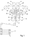
- a splicing device 11 is shown schematically, showing successive work steps.
- This splicing device 11 connects a first composite film 14 to a second composite film 15.
- a composite film 14, 15 can be made available to at least one subsequent processing station for processing or further processing of the composite film 14, 15 without downtime.
- Application-specific can according to figure 1 be provided that the splicing device 11 is connected downstream of a storage device 17, so that the subsequent processing stations can differ in terms of their processing speed from the splicing device 11 and still allow continuous processing of the composite film 14, 15.
- the splicing device 11 includes a first guide roller 21, via which the first composite film 14 is drawn off a supply roll 22 and fed to the splicing device 11.
- a second guide roller 23 can be provided opposite the first guide roller 21 and forms a first pair of guide rollers 24 with the guide roller 21 .
- the splicing device 11 comprises a further guide roller 25 via which the second composite film 15 is drawn off from a supply roll 26 and fed to the splicing device 11 .
- This guide roller 25 can be associated with a second guide roller 27 opposite. These can form a second pair of guide rollers 28 .
- At least the guide roller 21 and the guide roller 25 are driven and arranged at a distance from one another, so that the first composite film 14 and the second composite film 15 can be supplied independently and separately from one another.
- a clamping device 29 is provided downstream of the guide rollers 21, 25, between which a working gap 31 is formed.
- the clamping device 29 consists of mutually associated clamping jaws 30, which figure 1 in an open position 32 are shown. In this open position, the first and/or second composite film 14, 15 can be passed through freely.
- the splicing device 11 also includes a clamping holding device 35 which, viewed in the transport direction of the first and/or second film composite 14, 15, is located downstream of the clamping device 29.
- This clamping holding device 35 has two clamping blocks 36 lying opposite one another. These are in figure 1 in turn arranged in an open position 32, so that a working gap 31 is formed in between and the first and/or second composite film 14, 15 can be guided freely through it.
- the clamping blocks 36 each have vacuum bores aligned with the working gap 31, so that when a vacuum is applied, the first and/or second film composite 14, 15 rests against the clamping block 36 and is held by it.
- a cutting device 38 is provided between the clamping device 29 and the clamping holding device 35 .
- This cutting device 38 is shown in a rest position 39 .
- This cutting device 38 preferably consists of at least one cutting blade.
- This cutting device 38 can preferably be moved perpendicularly to the transport plane of the first and/or second film composite 14, 15.
- Guide plates 41 are provided below the clamping device 35 . These guide plates 41 can each be subjected to a vacuum. These guide plates 41 guide the first or second composite film 14, 15 from the clamping device 35 into a downstream connection station 44.
- the connecting station 44 preferably comprises two holding devices 45 which are arranged opposite one another and in turn form a working gap 31 lying between them.
- the holding devices 45 are preferably designed as vacuum rollers.
- the splicing device 11 is described below using the vacuum rollers 45 as an example, without being limited thereto.
- the vacuum rollers 45 rotate in opposite directions driven to each other, so that the first and / or second composite film 14, 15 can be moved in the transport direction. In particular, the first and/or second composite film 14, 15 is guided out of the splicing device 11 after the connecting station 44.
- a deflection roller 47 can be provided downstream of the splicing device 11 or at the outlet of the splicing device 11 in order to feed the film composite 14, 15 to the storage device 17 and/or to a further processing station, which is not shown.
- the vacuum roller 45 of the connecting station 44 preferably has a rubber coating on its outer circumference.
- the lateral surface of the vacuum roller 45 or the rubber coating of the vacuum roller 45 contains pores or bores, so that the outer lateral surface of the vacuum roller 45 can be subjected to a negative pressure.
- a connecting element 49 can be positioned on this vacuum roller 45 .
- This connecting element 49 can, for example, be in the form of an adhesive strip which, with its non-adhesive rear side, rests against the lateral surface of the vacuum roller 45 and is held in place by the vacuum. The adhesive layer is guided into the working gap 31 during a rotary movement in the transport direction of the vacuum roller 45 .
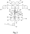
- the first composite film 14 has passed completely through the splicing device 11 .
- a beginning 51 of the second composite film 15 is fed to the splicing device 11 via the guide roller 25 .
- the beginning 51 of the second film composite 15 is fed in such a way that it is guided through the working gap 31 of the clamping device 29 and is positioned in the working gap 31 between the clamping device 35 ( figure 1 ).
- the connecting element 49 is positioned on the vacuum roller 45 before or up to this point in time.
- the connecting element 49 is cut to size in a separate work step that is not shown in detail.
- the length of the connecting element 49 preferably corresponds to the web width of the first and/or second film composite 14, 15.
- the width of the connecting element 49 can be designed depending on the holding force to be applied for the connection point 61 between the first and second film composite 14, 15 ( figure 6 ).
- the clamping device 29 and the clamping holding device 35 are preferably closed at the same time, preferably with a displacement movement according to arrow A, so that the first and second film composite are held clamped to one another in the respective working gap 31 ( figure 2 ).
- the cutting device 38 is activated. According to arrow B, a cutting blade can be moved.
- the first and second composite film 14, 15 are separated by the cutting device 38 and a joint joint 53 is formed.
- a negative pressure is applied to the clamping blocks 36.
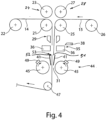
- the clamping device 29 and the clamping holding device 35 are moved back into an open position ( figure 3 ).
- the vacuum in the clamping blocks 36 holds a cut section 54 from the beginning 51 of the second film composite 15 and can then be disposed of in a defined manner. This can prevent this cut-off section 54 from causing a disruption in the further processing of the first and second film composite 14, 15 in subsequent stations.
- the joint 53 formed between the first and second composite film 14, 15 is supplied to the connection station 44 by the guide plates 41 in a supporting manner.
- the connecting element 49 is transferred into the working gap 31 at the same time as the stack 53.
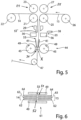
- the connecting elements 49 can each be attached, in particular glued, to the outside of the joint 53 at the end 52 of the first film composite 14 and the start 51 of the second film composite 15 . this is in figure 5 shown.
- the guide roller 27 and the vacuum rollers 45 of the connecting station 44 continue to be driven synchronously, and the connecting point 61, which connects the first and second film composite 14, 15, is guided out of the splicing device 11.
- the supply roll 22 of the first film composite 14 can be wound up so that the remaining second end 55 of the first film composite 14 ( figure 5 ) is led out of the splicing device 11 in order to subsequently change the supply roll with a new composite film.
- the subsequent splicing takes place as a mirror image of the work steps described above Figures 1 to 5 .
- FIG. 6 1 is a schematic sectional view of the splice 61 made with the splicing station 44.
- FIG. Through this connection point 61 is an end 52 of the first composite film 14 connected to the beginning 51 of the second film composite 15.
- the film composite 14, 15 is preferably constructed in three layers.
- This polymer layer 63 can be a photopolymer, in particular a polymer layer with holograms introduced therein.
- This polymer layer 63 is protected from damage by a protective layer 64 .
- This splicing device 11 has the advantage that such triple assemblies are connected to one another simply by lining them up. It is not necessary to detach the protective and/or carrier layer on one or both sides in order to connect the middle polymer layer.
- This splicing device 11 can also process a single-layer web material or a multi-layer film composite in a way that differs from the triple composite shown. ⁇ b>Reference List ⁇ /b> 11.
- Link station 68 21. Guide roller 45. Vacuum roller 69 22. Storage roll 46 70 23. Second leadership role 47. Pulley 71 24. 1st pair of guide rollers 48 72 25. Guide roller 49. Fastener 73 26. Storage roll 50 74 27. Second Guide Roller 51 beginning of 15 75 28. 2nd pair of guide rollers 52. End of 14 76 29. Clamping device 53rd shock 77 30. Jaw 54th section 78 31. Working gap 55 79 32. Opening position 56. Second end of 14 80 33 57 81 34 58 82
Landscapes
- Engineering & Computer Science (AREA)
- Mechanical Engineering (AREA)
- Replacement Of Web Rolls (AREA)
- Lining Or Joining Of Plastics Or The Like (AREA)
Claims (13)
- Procédé destiné à assembler par épissurage, dans un dispositif d'épissurage (11), une extrémité finale (52) d'un premier composite de feuilles (14) à une extrémité initiale (51) d'un deuxième composite de feuilles (15),- lors duquel le premier composite de feuilles (14) passe par le dispositif d'épissurage (11) et l'extrémité initiale (51) du deuxième composite de feuilles (15) est amenée au dispositif d'épissurage (11),- lors duquel le premier et le deuxième composite de feuilles (14, 15) sont coupés de manière à former un joint d'about (53),- lors duquel le joint d'about (53) formé par l'extrémité finale (52) du premier composite de feuilles (14) et l'extrémité initiale (51) du deuxième composite de feuilles (15) est amené à une station d'assemblage (44), et- lors duquel dans la station d'assemblage (44), un élément d'assemblage (49) est appliqué, d'un seul côté ou des deux côtés, sur une face extérieure du premier et du deuxième composite de feuilles (14, 15), et ce de manière à recouvrir le joint d'about (53) formé par ledit premier et ledit deuxième composite de feuilles (14, 15),caractérisé en ce que- le premier composite de feuilles (14) passe par un dispositif de serrage (29) et passe ensuite, dans le sens de transport, par un dispositif de maintien par serrage (35) et par la station d'assemblage (44), et en ce que le deuxième composite de feuilles (15) passe par le dispositif de serrage (29) et est amené au dispositif de maintien par serrage (35) qui vient juste après de sorte qu'au moins l'extrémité initiale (51) du deuxième composite de feuilles (15) est positionnée dans le dispositif de maintien par serrage (35), et- le dispositif de coupe (38) est positionné entre le dispositif de serrage (29) et le dispositif de maintien par serrage (35) et que, après la fermeture du dispositif de serrage (29) et du dispositif de maintien par serrage (35), le premier et le deuxième composite de feuilles (14, 15) sont coupés conjointement par le dispositif de coupe (38) de manière à former le joint d'about (53).
- Procédé selon la revendication 1, caractérisé en ce que la station d'assemblage (44) comprend un dispositif de maintien (45) et un élément de contre-maintien ou deux dispositifs de maintien (45) situés à l'opposé l'un de l'autre qui forment une fente de travail (31) dans laquelle sont introduits le premier et le deuxième composite de feuilles (14, 15), et en ce que ledit au moins un élément d'assemblage (49) est maintenu grâce à une force de maintien contre le dispositif de maintien (45) jusqu'à ce que soit réalisée l'insertion dans la fente de travail (31), et en ce que de préférence la force de maintien appliquée au niveau du dispositif de maintien (45) est mise à l'arrêt dès que l'élément d'assemblage (49) est passé dans la fente de travail (31).
- Procédé selon la revendication 2, caractérisé en ce que le dispositif de maintien (45) est réalisé en tant que cylindre à vide dans lequel la force de maintien destinée à recevoir ledit au moins un élément d'assemblage (49) est générée au niveau d'une surface circonférentielle du cylindre à vide grâce à l'application d'une pression négative.
- Procédé selon la revendication 3, caractérisé en ce qu'une bande adhésive ayant de préférence une surface adhésive sur une seule face est appliquée en tant qu'élément d'assemblage (49) sur le joint d'about (53) formé par le premier et le deuxième composite de feuilles (14, 15), et en ce que de préférence la bande adhésive est maintenue au niveau de sa face extérieure non adhésive par le cylindre à vide (45).
- Procédé selon l'une quelconque des revendications précédentes, caractérisé en ce que dans la station d'assemblage (44), l'élément d'assemblage (49) est appliqué simultanément des deux côtés, et ce respectivement sur la face extérieure du joint d'about (53) formé par le premier et le deuxième composite de feuilles (14, 15).
- Procédé selon la revendication 1, caractérisé en ce qu'après la coupe du joint d'about (53), le dispositif de serrage (29) et le dispositif de maintien par serrage (35) sont ouverts, l'un des deux blocs de serrage (36) du dispositif de maintien par serrage (35) étant soumis à une pression négative et une partie (54) coupée au niveau de l'extrémité initiale (51) du deuxième composite de feuilles (15) étant retirée du point de coupe.
- Procédé selon l'une quelconque des revendications 1 ou 6, caractérisé en ce que le joint d'about (53) entre le premier et le deuxième composite de feuilles (14, 15) quitte le dispositif de maintien par serrage (35) pour passer dans la station d'assemblage (45) grâce à des tôles déflectrices (41) qui sont de préférence soumises à une pression négative.
- Procédé selon l'une quelconque des revendications 3-7, caractérisé en ce que lorsque le joint d'about (53) passe du point de coupe à la station d'assemblage (44), un cylindre d'amenée (27) ou une paire de cylindres d'amenée (28) du deuxième composite de feuilles (15) et les cylindres à vide (45) de la station d'assemblage (44) sont activés de manière à présenter une vitesse de bande synchronisée.
- Procédé selon l'une quelconque des revendications précédentes, caractérisé en ce qu'un premier et un deuxième composite de feuilles (14, 15) formés d'une ou de plusieurs couches, formés en particulier en tant que tricomposites comprenant une couche support (62), une couche de polymère (63) et une couche protectrice (64), sont amenés au dispositif d'épissurage (11).
- Dispositif d'épissurage destiné à assembler par épissurage une extrémité finale d'un premier composite de feuilles (14) à une extrémité initiale (51) d'un deuxième composite de feuilles (15),- pourvu d'au moins un dispositif de coupe (38) grâce auquel il est possible de fabriquer un joint d'about commun (53) entre le premier et le deuxième composite de feuilles (14, 15), et- pourvu d'une station d'assemblage (44) qui amène d'un seul côté ou des deux côtés au moins un élément d'assemblage (49) au joint d'about (53) formé par le premier et le deuxième composite de feuilles (14, 15) et l'applique de manière à recouvrir ledit joint d'about (53),caractérisé en ce que- le premier composite de feuilles (14) peut passer par un dispositif de serrage (29) et peut ensuite passer, dans le sens de transport, par un dispositif de maintien par serrage (35) et par la station d'assemblage (44), et en ce que le deuxième composite de feuilles (15) peut passer par le dispositif de serrage (29) et peut être amené au dispositif de maintien par serrage (35) qui vient juste après de sorte qu'au moins l'extrémité initiale (51) du deuxième composite de feuilles (15) est positionnée dans le dispositif de maintien par serrage (35), et- le dispositif de coupe (38) est positionné entre le dispositif de serrage (29) et le dispositif de maintien par serrage (35) et que le premier et le deuxième composite de feuilles (14, 15) sont maintenus ensemble par serrage par ledit dispositif de serrage (29) et ledit dispositif de maintien par serrage (35) et que le joint d'about (53) peut être réalisé grâce au dispositif de coupe (38).
- Dispositif d'épissurage selon la revendication 10, caractérisé en ce que la station d'assemblage (44) présente un dispositif de maintien (45) et un élément de contre-maintien ou deux dispositifs de maintien (45) disposés à l'opposé l'un de l'autre entre lesquels est formée une fente de travail (31) destiné à appliquer ledit au moins un élément d'assemblage (49) sur le joint d'about (53) formé par le premier et le deuxième composite de feuilles (14, 15), et en ce que de préférence le dispositif de maintien (45) est formé en tant que cylindre à vide qui présente comme surface latérale un revêtement extérieur en caoutchouc qui comprend une pluralité de trous de passage, et/ou en ce que le dispositif de maintien (45) présente un marquage et/ou un élément d'alignement en vue de mettre en place l'élément d'assemblage (49).
- Dispositif d'épissurage selon l'une quelconque des revendications 10 ou 11, caractérisé en ce qu'au dispositif de coupe (38) est affecté un dispositif de maintien par serrage (35) qui est en particulier placé en aval dans le sens de transport du premier et du deuxième composite de feuilles (14, 15) et qui peut passer dans une position d'ouverture ou de fermeture, et en ce qu'un dispositif de serrage (29) qui peut passer dans une position d'ouverture et une position de fermeture est prévu, vu dans le sens de transport du premier et du deuxième composite de feuilles (14, 15), avant le dispositif de coupe (38), et en ce que de préférence entre le dispositif de maintien par serrage (35) et la station d'assemblage (44) sont prévues des tôles déflectrices (41) situées à l'opposé l'une de l'autre qui peuvent être de préférence soumises à une pression négative.
- Dispositif d'épissurage selon l'une quelconque des revendications 11 à 12, caractérisé en ce que pour le premier composite de feuilles (14) et pour le deuxième composite de feuilles (15) est prévu respectivement au moins un cylindre de guidage (21, 15) qui est placé en amont du dispositif de coupe (38), et en ce que le cylindre de guidage (21, 25) et les cylindres à vide (45) de la station d'assemblage (44) peuvent être activés de manière synchronisée.
Applications Claiming Priority (1)
| Application Number | Priority Date | Filing Date | Title |
|---|---|---|---|
| DE102018130674.1A DE102018130674B4 (de) | 2018-12-03 | 2018-12-03 | Verfahren und Vorrichtung zum Spleißen von einem ersten und einem zweiten Folienverbund |
Publications (2)
| Publication Number | Publication Date |
|---|---|
| EP3663243A1 EP3663243A1 (fr) | 2020-06-10 |
| EP3663243B1 true EP3663243B1 (fr) | 2023-09-06 |
Family
ID=68762538
Family Applications (1)
| Application Number | Title | Priority Date | Filing Date |
|---|---|---|---|
| EP19212787.6A Active EP3663243B1 (fr) | 2018-12-03 | 2019-12-02 | Procédé et dispositif d'épissure d'un premier et d'un deuxième films composites |
Country Status (2)
| Country | Link |
|---|---|
| EP (1) | EP3663243B1 (fr) |
| DE (1) | DE102018130674B4 (fr) |
Families Citing this family (6)
| Publication number | Priority date | Publication date | Assignee | Title |
|---|---|---|---|---|
| CN113103728B (zh) * | 2021-05-19 | 2022-10-28 | 上海紫江彩印包装有限公司 | 一种易撕复合膜的在线制备方法、系统装置及其制备的复合膜 |
| CN114408635A (zh) * | 2021-12-22 | 2022-04-29 | 软控股份有限公司 | 胶条自动续料装置 |
| CN115416317B (zh) * | 2022-09-06 | 2025-09-05 | 深圳鑫富艺科技股份有限公司 | 一种bp膜和cop膜拼接设备及拼接工艺方法 |
| CN116902647B (zh) * | 2023-06-02 | 2024-05-03 | 临沂驰禾塑料制品有限公司 | 一种复合包装膜加工工艺及其加工设备 |
| CN119706463A (zh) * | 2023-09-28 | 2025-03-28 | 宁德时代新能源科技股份有限公司 | 切割拼接装置、包膜系统和料带切割拼接方法 |
| DE102024119966A1 (de) * | 2024-07-12 | 2026-01-15 | Mb Automation Gmbh & Co. Kg | Vorrichtung und Verfahren zum Spleißen wenigstens zweilagiger Material-Bahnen |
Family Cites Families (11)
| Publication number | Priority date | Publication date | Assignee | Title |
|---|---|---|---|---|
| JPS5329174B2 (fr) | 1973-11-29 | 1978-08-18 | ||
| FR2679888B1 (fr) | 1991-08-02 | 1993-11-26 | Du Pont De Nemours And Cy | Procede et dispositif pour raccorder en continuite deux feuils minces. |
| US5698060A (en) * | 1995-12-14 | 1997-12-16 | Eastman Kodak Company | Web butt-splicing apparatus |
| DE69941094D1 (de) | 1999-02-03 | 2009-08-20 | Goodyear Tire & Rubber | Stossverbinden von gummibahnen |
| US6533891B1 (en) | 1999-02-03 | 2003-03-18 | The Goodyear Tire & Rubber Company | Butt splicing of elastomeric sheets |
| DE19962413A1 (de) | 1999-12-22 | 2001-06-28 | Kiener Maschinenbau Gmbh | Verfahren und Vorrichtung zum Herstellen eines zumindest eine Polymerfolie mit Informationen und zumindest eine Trägerschicht enthaltenden Verbundes zur Weiterverarbeitung für fälschungssichere Dokumente |
| DE10226148B4 (de) | 2002-06-13 | 2011-11-17 | Tetra Laval Holdings & Finance S.A. | Vorrichtung zum Verkleben zweier Verpackungsmaterialbahnen |
| US7073552B2 (en) | 2002-12-20 | 2006-07-11 | The Goodyear Tire & Rubber Company | Tire preparation ply manufacturing apparatus and method |
| JP4487315B2 (ja) * | 2005-08-31 | 2010-06-23 | 富士フイルム株式会社 | ウエブの突き合わせ接合方法及び装置 |
| DE102011111786A1 (de) | 2011-09-01 | 2013-03-07 | Ovd Kinegram Ag | Verfahren und Vorrichtung zum Verbinden von Transfer- oder Laminierfolienbahnen |
| DE102015210522A1 (de) | 2015-06-09 | 2016-12-15 | Bundesdruckerei Gmbh | Verfahren und Vorrichtung zum Herstellen eines Sicherheitselemente aufweisenden mehrlagigen Wert- oder Sicherheitsdokuments |
-
2018
- 2018-12-03 DE DE102018130674.1A patent/DE102018130674B4/de active Active
-
2019
- 2019-12-02 EP EP19212787.6A patent/EP3663243B1/fr active Active
Also Published As
| Publication number | Publication date |
|---|---|
| DE102018130674B4 (de) | 2021-12-23 |
| DE102018130674A1 (de) | 2020-06-04 |
| EP3663243A1 (fr) | 2020-06-10 |
Similar Documents
| Publication | Publication Date | Title |
|---|---|---|
| EP3663243B1 (fr) | Procédé et dispositif d'épissure d'un premier et d'un deuxième films composites | |
| DE60110653T2 (de) | Vorrichtung und Verfahren zum Verbinden von Folienrollen | |
| DE3811138C2 (fr) | ||
| DE2107677B2 (de) | Vorrichtung zum stampfen Verbinden des Hinterendes eines auslaufenden Bahnmaterials mit dem Vorderende eines neuen Bahnmaterials | |
| DE69208883T2 (de) | Methode und vorrichtung zu auflegen von mit haftkleber versehen blättern | |
| DE3334009C2 (de) | Vorrichtung zum Laminieren eines Folienstückes auf einen plattenförmigen Gegenstand | |
| DE4139586C2 (de) | Verfahren und Vorrichtung zum Bilden und Erfassen eines Bahnanfanges einer Ersatz-Wickelrolle | |
| DE69600379T2 (de) | Verfahren und Vorrichtung zum Aufbringen eines Films auf eine Oberfläche | |
| EP3416905B1 (fr) | Procédé et dispositif d'obtention d'une feuille séparée dans un dispositif d'impression | |
| DE69507674T2 (de) | Verfahren zum Herstellen eines flachen Kabelbaumes | |
| DE2751862A1 (de) | Verfahren und vorrichtung zum abstreifen und entwickeln eines lichtempfindlichen materials | |
| EP1749590B1 (fr) | Procédé d'application d'adhésifs sur une liaison entre deux bandes et applicateur de ruban adhésif | |
| DE2256364C2 (de) | Klebegerät | |
| DE19607495A1 (de) | Verfahren und Vorrichtung zum automatischen Wechsel von Folienrollen, insbesondere bei der Herstellung von Faltschachteln mit Folienfenstern | |
| EP3526497B1 (fr) | Procédé pour produire un matériau en bande continue destiné à la réalisation de joints d'étanchéité et bande continue | |
| DE69230396T2 (de) | Verfahren und Vorrichtung zum Beschichten von Filmen | |
| WO2024028168A1 (fr) | Dispositif et procédé de raccordement de bandes de matériau continues | |
| DE102016206656A1 (de) | Perforierte Etiketten durch Drehbewegung ausrichten und greifen | |
| DE2547699A1 (de) | Verfahren und anlage zur herstellung thermoplastischer folie | |
| DE102020118023A1 (de) | Rollenabwickler, Rollendruckmaschine sowie Verfahren zum Betreiben eines Rollenabwicklers | |
| DE3203644A1 (de) | Verfahren und vorrichtung zum automatischen spleissen bzw. verbinden von folien | |
| EP1014768B1 (fr) | Procédé et dispositif pour la fabrication de multicouches | |
| DE3503715C2 (fr) | ||
| EP3556556A1 (fr) | Dispositif de revêtement | |
| EP4263200B1 (fr) | Dispositif de séparation et procédé pour séparer localement une bande de film |
Legal Events
| Date | Code | Title | Description |
|---|---|---|---|
| PUAI | Public reference made under article 153(3) epc to a published international application that has entered the european phase |
Free format text: ORIGINAL CODE: 0009012 |
|
| STAA | Information on the status of an ep patent application or granted ep patent |
Free format text: STATUS: THE APPLICATION HAS BEEN PUBLISHED |
|
| AK | Designated contracting states |
Kind code of ref document: A1 Designated state(s): AL AT BE BG CH CY CZ DE DK EE ES FI FR GB GR HR HU IE IS IT LI LT LU LV MC MK MT NL NO PL PT RO RS SE SI SK SM TR |
|
| AX | Request for extension of the european patent |
Extension state: BA ME |
|
| STAA | Information on the status of an ep patent application or granted ep patent |
Free format text: STATUS: REQUEST FOR EXAMINATION WAS MADE |
|
| 17P | Request for examination filed |
Effective date: 20201210 |
|
| RBV | Designated contracting states (corrected) |
Designated state(s): AL AT BE BG CH CY CZ DE DK EE ES FI FR GB GR HR HU IE IS IT LI LT LU LV MC MK MT NL NO PL PT RO RS SE SI SK SM TR |
|
| RIC1 | Information provided on ipc code assigned before grant |
Ipc: B29C 65/50 20060101ALI20220820BHEP Ipc: B29C 65/00 20060101ALI20220820BHEP Ipc: B29C 65/78 20060101ALI20220820BHEP Ipc: B65H 19/18 20060101AFI20220820BHEP |
|
| GRAP | Despatch of communication of intention to grant a patent |
Free format text: ORIGINAL CODE: EPIDOSNIGR1 |
|
| STAA | Information on the status of an ep patent application or granted ep patent |
Free format text: STATUS: GRANT OF PATENT IS INTENDED |
|
| INTG | Intention to grant announced |
Effective date: 20221202 |
|
| GRAJ | Information related to disapproval of communication of intention to grant by the applicant or resumption of examination proceedings by the epo deleted |
Free format text: ORIGINAL CODE: EPIDOSDIGR1 |
|
| STAA | Information on the status of an ep patent application or granted ep patent |
Free format text: STATUS: REQUEST FOR EXAMINATION WAS MADE |
|
| INTC | Intention to grant announced (deleted) | ||
| P01 | Opt-out of the competence of the unified patent court (upc) registered |
Effective date: 20230526 |
|
| GRAP | Despatch of communication of intention to grant a patent |
Free format text: ORIGINAL CODE: EPIDOSNIGR1 |
|
| STAA | Information on the status of an ep patent application or granted ep patent |
Free format text: STATUS: GRANT OF PATENT IS INTENDED |
|
| GRAS | Grant fee paid |
Free format text: ORIGINAL CODE: EPIDOSNIGR3 |
|
| INTG | Intention to grant announced |
Effective date: 20230707 |
|
| GRAA | (expected) grant |
Free format text: ORIGINAL CODE: 0009210 |
|
| STAA | Information on the status of an ep patent application or granted ep patent |
Free format text: STATUS: THE PATENT HAS BEEN GRANTED |
|
| AK | Designated contracting states |
Kind code of ref document: B1 Designated state(s): AL AT BE BG CH CY CZ DE DK EE ES FI FR GB GR HR HU IE IS IT LI LT LU LV MC MK MT NL NO PL PT RO RS SE SI SK SM TR |
|
| REG | Reference to a national code |
Ref country code: GB Ref legal event code: FG4D Free format text: NOT ENGLISH |
|
| REG | Reference to a national code |
Ref country code: CH Ref legal event code: EP |
|
| REG | Reference to a national code |
Ref country code: IE Ref legal event code: FG4D Free format text: LANGUAGE OF EP DOCUMENT: GERMAN |
|
| REG | Reference to a national code |
Ref country code: DE Ref legal event code: R096 Ref document number: 502019009239 Country of ref document: DE |
|
| REG | Reference to a national code |
Ref country code: LT Ref legal event code: MG9D |
|
| REG | Reference to a national code |
Ref country code: NL Ref legal event code: MP Effective date: 20230906 |
|
| PG25 | Lapsed in a contracting state [announced via postgrant information from national office to epo] |
Ref country code: GR Free format text: LAPSE BECAUSE OF FAILURE TO SUBMIT A TRANSLATION OF THE DESCRIPTION OR TO PAY THE FEE WITHIN THE PRESCRIBED TIME-LIMIT Effective date: 20231207 |
|
| PG25 | Lapsed in a contracting state [announced via postgrant information from national office to epo] |
Ref country code: SE Free format text: LAPSE BECAUSE OF FAILURE TO SUBMIT A TRANSLATION OF THE DESCRIPTION OR TO PAY THE FEE WITHIN THE PRESCRIBED TIME-LIMIT Effective date: 20230906 Ref country code: RS Free format text: LAPSE BECAUSE OF FAILURE TO SUBMIT A TRANSLATION OF THE DESCRIPTION OR TO PAY THE FEE WITHIN THE PRESCRIBED TIME-LIMIT Effective date: 20230906 Ref country code: NO Free format text: LAPSE BECAUSE OF FAILURE TO SUBMIT A TRANSLATION OF THE DESCRIPTION OR TO PAY THE FEE WITHIN THE PRESCRIBED TIME-LIMIT Effective date: 20231206 Ref country code: LV Free format text: LAPSE BECAUSE OF FAILURE TO SUBMIT A TRANSLATION OF THE DESCRIPTION OR TO PAY THE FEE WITHIN THE PRESCRIBED TIME-LIMIT Effective date: 20230906 Ref country code: LT Free format text: LAPSE BECAUSE OF FAILURE TO SUBMIT A TRANSLATION OF THE DESCRIPTION OR TO PAY THE FEE WITHIN THE PRESCRIBED TIME-LIMIT Effective date: 20230906 Ref country code: HR Free format text: LAPSE BECAUSE OF FAILURE TO SUBMIT A TRANSLATION OF THE DESCRIPTION OR TO PAY THE FEE WITHIN THE PRESCRIBED TIME-LIMIT Effective date: 20230906 Ref country code: GR Free format text: LAPSE BECAUSE OF FAILURE TO SUBMIT A TRANSLATION OF THE DESCRIPTION OR TO PAY THE FEE WITHIN THE PRESCRIBED TIME-LIMIT Effective date: 20231207 Ref country code: FI Free format text: LAPSE BECAUSE OF FAILURE TO SUBMIT A TRANSLATION OF THE DESCRIPTION OR TO PAY THE FEE WITHIN THE PRESCRIBED TIME-LIMIT Effective date: 20230906 |
|
| PG25 | Lapsed in a contracting state [announced via postgrant information from national office to epo] |
Ref country code: NL Free format text: LAPSE BECAUSE OF FAILURE TO SUBMIT A TRANSLATION OF THE DESCRIPTION OR TO PAY THE FEE WITHIN THE PRESCRIBED TIME-LIMIT Effective date: 20230906 |
|
| PG25 | Lapsed in a contracting state [announced via postgrant information from national office to epo] |
Ref country code: IS Free format text: LAPSE BECAUSE OF FAILURE TO SUBMIT A TRANSLATION OF THE DESCRIPTION OR TO PAY THE FEE WITHIN THE PRESCRIBED TIME-LIMIT Effective date: 20240106 |
|
| PG25 | Lapsed in a contracting state [announced via postgrant information from national office to epo] |
Ref country code: ES Free format text: LAPSE BECAUSE OF FAILURE TO SUBMIT A TRANSLATION OF THE DESCRIPTION OR TO PAY THE FEE WITHIN THE PRESCRIBED TIME-LIMIT Effective date: 20230906 |
|
| PG25 | Lapsed in a contracting state [announced via postgrant information from national office to epo] |
Ref country code: SM Free format text: LAPSE BECAUSE OF FAILURE TO SUBMIT A TRANSLATION OF THE DESCRIPTION OR TO PAY THE FEE WITHIN THE PRESCRIBED TIME-LIMIT Effective date: 20230906 Ref country code: RO Free format text: LAPSE BECAUSE OF FAILURE TO SUBMIT A TRANSLATION OF THE DESCRIPTION OR TO PAY THE FEE WITHIN THE PRESCRIBED TIME-LIMIT Effective date: 20230906 Ref country code: IS Free format text: LAPSE BECAUSE OF FAILURE TO SUBMIT A TRANSLATION OF THE DESCRIPTION OR TO PAY THE FEE WITHIN THE PRESCRIBED TIME-LIMIT Effective date: 20240106 Ref country code: ES Free format text: LAPSE BECAUSE OF FAILURE TO SUBMIT A TRANSLATION OF THE DESCRIPTION OR TO PAY THE FEE WITHIN THE PRESCRIBED TIME-LIMIT Effective date: 20230906 Ref country code: EE Free format text: LAPSE BECAUSE OF FAILURE TO SUBMIT A TRANSLATION OF THE DESCRIPTION OR TO PAY THE FEE WITHIN THE PRESCRIBED TIME-LIMIT Effective date: 20230906 Ref country code: CZ Free format text: LAPSE BECAUSE OF FAILURE TO SUBMIT A TRANSLATION OF THE DESCRIPTION OR TO PAY THE FEE WITHIN THE PRESCRIBED TIME-LIMIT Effective date: 20230906 Ref country code: SK Free format text: LAPSE BECAUSE OF FAILURE TO SUBMIT A TRANSLATION OF THE DESCRIPTION OR TO PAY THE FEE WITHIN THE PRESCRIBED TIME-LIMIT Effective date: 20230906 Ref country code: PT Free format text: LAPSE BECAUSE OF FAILURE TO SUBMIT A TRANSLATION OF THE DESCRIPTION OR TO PAY THE FEE WITHIN THE PRESCRIBED TIME-LIMIT Effective date: 20240108 |
|
| PG25 | Lapsed in a contracting state [announced via postgrant information from national office to epo] |
Ref country code: PL Free format text: LAPSE BECAUSE OF FAILURE TO SUBMIT A TRANSLATION OF THE DESCRIPTION OR TO PAY THE FEE WITHIN THE PRESCRIBED TIME-LIMIT Effective date: 20230906 Ref country code: IT Free format text: LAPSE BECAUSE OF FAILURE TO SUBMIT A TRANSLATION OF THE DESCRIPTION OR TO PAY THE FEE WITHIN THE PRESCRIBED TIME-LIMIT Effective date: 20230906 |
|
| REG | Reference to a national code |
Ref country code: DE Ref legal event code: R097 Ref document number: 502019009239 Country of ref document: DE |
|
| PG25 | Lapsed in a contracting state [announced via postgrant information from national office to epo] |
Ref country code: DK Free format text: LAPSE BECAUSE OF FAILURE TO SUBMIT A TRANSLATION OF THE DESCRIPTION OR TO PAY THE FEE WITHIN THE PRESCRIBED TIME-LIMIT Effective date: 20230906 |
|
| PLBE | No opposition filed within time limit |
Free format text: ORIGINAL CODE: 0009261 |
|
| STAA | Information on the status of an ep patent application or granted ep patent |
Free format text: STATUS: NO OPPOSITION FILED WITHIN TIME LIMIT |
|
| PG25 | Lapsed in a contracting state [announced via postgrant information from national office to epo] |
Ref country code: DK Free format text: LAPSE BECAUSE OF FAILURE TO SUBMIT A TRANSLATION OF THE DESCRIPTION OR TO PAY THE FEE WITHIN THE PRESCRIBED TIME-LIMIT Effective date: 20230906 Ref country code: SI Free format text: LAPSE BECAUSE OF FAILURE TO SUBMIT A TRANSLATION OF THE DESCRIPTION OR TO PAY THE FEE WITHIN THE PRESCRIBED TIME-LIMIT Effective date: 20230906 |
|
| REG | Reference to a national code |
Ref country code: CH Ref legal event code: PL |
|
| 26N | No opposition filed |
Effective date: 20240607 |
|
| PG25 | Lapsed in a contracting state [announced via postgrant information from national office to epo] |
Ref country code: LU Free format text: LAPSE BECAUSE OF NON-PAYMENT OF DUE FEES Effective date: 20231202 |
|
| PG25 | Lapsed in a contracting state [announced via postgrant information from national office to epo] |
Ref country code: MC Free format text: LAPSE BECAUSE OF FAILURE TO SUBMIT A TRANSLATION OF THE DESCRIPTION OR TO PAY THE FEE WITHIN THE PRESCRIBED TIME-LIMIT Effective date: 20230906 |
|
| REG | Reference to a national code |
Ref country code: BE Ref legal event code: MM Effective date: 20231231 |
|
| PG25 | Lapsed in a contracting state [announced via postgrant information from national office to epo] |
Ref country code: MC Free format text: LAPSE BECAUSE OF FAILURE TO SUBMIT A TRANSLATION OF THE DESCRIPTION OR TO PAY THE FEE WITHIN THE PRESCRIBED TIME-LIMIT Effective date: 20230906 Ref country code: LU Free format text: LAPSE BECAUSE OF NON-PAYMENT OF DUE FEES Effective date: 20231202 |
|
| REG | Reference to a national code |
Ref country code: IE Ref legal event code: MM4A |
|
| PG25 | Lapsed in a contracting state [announced via postgrant information from national office to epo] |
Ref country code: IE Free format text: LAPSE BECAUSE OF NON-PAYMENT OF DUE FEES Effective date: 20231202 |
|
| PG25 | Lapsed in a contracting state [announced via postgrant information from national office to epo] |
Ref country code: BE Free format text: LAPSE BECAUSE OF NON-PAYMENT OF DUE FEES Effective date: 20231231 |
|
| PG25 | Lapsed in a contracting state [announced via postgrant information from national office to epo] |
Ref country code: CH Free format text: LAPSE BECAUSE OF NON-PAYMENT OF DUE FEES Effective date: 20231231 |
|
| PG25 | Lapsed in a contracting state [announced via postgrant information from national office to epo] |
Ref country code: IE Free format text: LAPSE BECAUSE OF NON-PAYMENT OF DUE FEES Effective date: 20231202 Ref country code: CH Free format text: LAPSE BECAUSE OF NON-PAYMENT OF DUE FEES Effective date: 20231231 Ref country code: BE Free format text: LAPSE BECAUSE OF NON-PAYMENT OF DUE FEES Effective date: 20231231 |
|
| PG25 | Lapsed in a contracting state [announced via postgrant information from national office to epo] |
Ref country code: BG Free format text: LAPSE BECAUSE OF FAILURE TO SUBMIT A TRANSLATION OF THE DESCRIPTION OR TO PAY THE FEE WITHIN THE PRESCRIBED TIME-LIMIT Effective date: 20230906 |
|
| PG25 | Lapsed in a contracting state [announced via postgrant information from national office to epo] |
Ref country code: BG Free format text: LAPSE BECAUSE OF FAILURE TO SUBMIT A TRANSLATION OF THE DESCRIPTION OR TO PAY THE FEE WITHIN THE PRESCRIBED TIME-LIMIT Effective date: 20230906 |
|
| PG25 | Lapsed in a contracting state [announced via postgrant information from national office to epo] |
Ref country code: CY Free format text: LAPSE BECAUSE OF FAILURE TO SUBMIT A TRANSLATION OF THE DESCRIPTION OR TO PAY THE FEE WITHIN THE PRESCRIBED TIME-LIMIT; INVALID AB INITIO Effective date: 20191202 |
|
| PG25 | Lapsed in a contracting state [announced via postgrant information from national office to epo] |
Ref country code: HU Free format text: LAPSE BECAUSE OF FAILURE TO SUBMIT A TRANSLATION OF THE DESCRIPTION OR TO PAY THE FEE WITHIN THE PRESCRIBED TIME-LIMIT; INVALID AB INITIO Effective date: 20191202 |
|
| PG25 | Lapsed in a contracting state [announced via postgrant information from national office to epo] |
Ref country code: TR Free format text: LAPSE BECAUSE OF FAILURE TO SUBMIT A TRANSLATION OF THE DESCRIPTION OR TO PAY THE FEE WITHIN THE PRESCRIBED TIME-LIMIT Effective date: 20230906 |
|
| PGFP | Annual fee paid to national office [announced via postgrant information from national office to epo] |
Ref country code: GB Payment date: 20251218 Year of fee payment: 7 |
|
| PGFP | Annual fee paid to national office [announced via postgrant information from national office to epo] |
Ref country code: FR Payment date: 20251217 Year of fee payment: 7 |
|
| REG | Reference to a national code |
Ref country code: AT Ref legal event code: MM01 Ref document number: 1608315 Country of ref document: AT Kind code of ref document: T Effective date: 20241202 |
|
| PGFP | Annual fee paid to national office [announced via postgrant information from national office to epo] |
Ref country code: DE Payment date: 20251222 Year of fee payment: 7 |
|
| PG25 | Lapsed in a contracting state [announced via postgrant information from national office to epo] |
Ref country code: AT Free format text: LAPSE BECAUSE OF NON-PAYMENT OF DUE FEES Effective date: 20241202 |
|
| PGFP | Annual fee paid to national office [announced via postgrant information from national office to epo] |
Ref country code: AT Payment date: 20260410 Year of fee payment: 5 |