EP3663243A1 - Procédé et dispositif d'épissure d'un premier et d'un deuxième films composites - Google Patents
Procédé et dispositif d'épissure d'un premier et d'un deuxième films composites Download PDFInfo
- Publication number
- EP3663243A1 EP3663243A1 EP19212787.6A EP19212787A EP3663243A1 EP 3663243 A1 EP3663243 A1 EP 3663243A1 EP 19212787 A EP19212787 A EP 19212787A EP 3663243 A1 EP3663243 A1 EP 3663243A1
- Authority
- EP
- European Patent Office
- Prior art keywords
- film composite
- clamping
- joint
- holding
- splicing
- Prior art date
- Legal status (The legal status is an assumption and is not a legal conclusion. Google has not performed a legal analysis and makes no representation as to the accuracy of the status listed.)
- Granted
Links
Images


Classifications
-
- B—PERFORMING OPERATIONS; TRANSPORTING
- B65—CONVEYING; PACKING; STORING; HANDLING THIN OR FILAMENTARY MATERIAL
- B65H—HANDLING THIN OR FILAMENTARY MATERIAL, e.g. SHEETS, WEBS, CABLES
- B65H19/00—Changing the web roll
- B65H19/10—Changing the web roll in unwinding mechanisms or in connection with unwinding operations
- B65H19/18—Attaching, e.g. pasting, the replacement web to the expiring web
- B65H19/1805—Flying splicing, i.e. the expiring web moving during splicing contact
- B65H19/1826—Flying splicing, i.e. the expiring web moving during splicing contact taking place at a distance from the replacement roll
- B65H19/1831—Flying splicing, i.e. the expiring web moving during splicing contact taking place at a distance from the replacement roll the replacement web being stationary prior to splicing contact
-
- B—PERFORMING OPERATIONS; TRANSPORTING
- B29—WORKING OF PLASTICS; WORKING OF SUBSTANCES IN A PLASTIC STATE IN GENERAL
- B29C—SHAPING OR JOINING OF PLASTICS; SHAPING OF MATERIAL IN A PLASTIC STATE, NOT OTHERWISE PROVIDED FOR; AFTER-TREATMENT OF THE SHAPED PRODUCTS, e.g. REPAIRING
- B29C65/00—Joining or sealing of preformed parts, e.g. welding of plastics materials; Apparatus therefor
- B29C65/48—Joining or sealing of preformed parts, e.g. welding of plastics materials; Apparatus therefor using adhesives, i.e. using supplementary joining material; solvent bonding
- B29C65/50—Joining or sealing of preformed parts, e.g. welding of plastics materials; Apparatus therefor using adhesives, i.e. using supplementary joining material; solvent bonding using adhesive tape, e.g. thermoplastic tape; using threads or the like
- B29C65/5042—Joining or sealing of preformed parts, e.g. welding of plastics materials; Apparatus therefor using adhesives, i.e. using supplementary joining material; solvent bonding using adhesive tape, e.g. thermoplastic tape; using threads or the like covering both elements to be joined
-
- B—PERFORMING OPERATIONS; TRANSPORTING
- B29—WORKING OF PLASTICS; WORKING OF SUBSTANCES IN A PLASTIC STATE IN GENERAL
- B29C—SHAPING OR JOINING OF PLASTICS; SHAPING OF MATERIAL IN A PLASTIC STATE, NOT OTHERWISE PROVIDED FOR; AFTER-TREATMENT OF THE SHAPED PRODUCTS, e.g. REPAIRING
- B29C65/00—Joining or sealing of preformed parts, e.g. welding of plastics materials; Apparatus therefor
- B29C65/78—Means for handling the parts to be joined, e.g. for making containers or hollow articles, e.g. means for handling sheets, plates, web-like materials, tubular articles, hollow articles or elements to be joined therewith; Means for discharging the joined articles from the joining apparatus
- B29C65/7858—Means for handling the parts to be joined, e.g. for making containers or hollow articles, e.g. means for handling sheets, plates, web-like materials, tubular articles, hollow articles or elements to be joined therewith; Means for discharging the joined articles from the joining apparatus characterised by the feeding movement of the parts to be joined
- B29C65/7888—Means for handling of moving sheets or webs
- B29C65/7894—Means for handling of moving sheets or webs of continuously moving sheets or webs
-
- B—PERFORMING OPERATIONS; TRANSPORTING
- B29—WORKING OF PLASTICS; WORKING OF SUBSTANCES IN A PLASTIC STATE IN GENERAL
- B29C—SHAPING OR JOINING OF PLASTICS; SHAPING OF MATERIAL IN A PLASTIC STATE, NOT OTHERWISE PROVIDED FOR; AFTER-TREATMENT OF THE SHAPED PRODUCTS, e.g. REPAIRING
- B29C66/00—General aspects of processes or apparatus for joining preformed parts
- B29C66/01—General aspects dealing with the joint area or with the area to be joined
- B29C66/05—Particular design of joint configurations
- B29C66/10—Particular design of joint configurations particular design of the joint cross-sections
- B29C66/11—Joint cross-sections comprising a single joint-segment, i.e. one of the parts to be joined comprising a single joint-segment in the joint cross-section
- B29C66/114—Single butt joints
- B29C66/1142—Single butt to butt joints
-
- B—PERFORMING OPERATIONS; TRANSPORTING
- B29—WORKING OF PLASTICS; WORKING OF SUBSTANCES IN A PLASTIC STATE IN GENERAL
- B29C—SHAPING OR JOINING OF PLASTICS; SHAPING OF MATERIAL IN A PLASTIC STATE, NOT OTHERWISE PROVIDED FOR; AFTER-TREATMENT OF THE SHAPED PRODUCTS, e.g. REPAIRING
- B29C66/00—General aspects of processes or apparatus for joining preformed parts
- B29C66/40—General aspects of joining substantially flat articles, e.g. plates, sheets or web-like materials; Making flat seams in tubular or hollow articles; Joining single elements to substantially flat surfaces
- B29C66/41—Joining substantially flat articles ; Making flat seams in tubular or hollow articles
- B29C66/43—Joining a relatively small portion of the surface of said articles
-
- B—PERFORMING OPERATIONS; TRANSPORTING
- B29—WORKING OF PLASTICS; WORKING OF SUBSTANCES IN A PLASTIC STATE IN GENERAL
- B29C—SHAPING OR JOINING OF PLASTICS; SHAPING OF MATERIAL IN A PLASTIC STATE, NOT OTHERWISE PROVIDED FOR; AFTER-TREATMENT OF THE SHAPED PRODUCTS, e.g. REPAIRING
- B29C66/00—General aspects of processes or apparatus for joining preformed parts
- B29C66/70—General aspects of processes or apparatus for joining preformed parts characterised by the composition, physical properties or the structure of the material of the parts to be joined; Joining with non-plastics material
- B29C66/72—General aspects of processes or apparatus for joining preformed parts characterised by the composition, physical properties or the structure of the material of the parts to be joined; Joining with non-plastics material characterised by the structure of the material of the parts to be joined
- B29C66/723—General aspects of processes or apparatus for joining preformed parts characterised by the composition, physical properties or the structure of the material of the parts to be joined; Joining with non-plastics material characterised by the structure of the material of the parts to be joined being multi-layered
-
- B—PERFORMING OPERATIONS; TRANSPORTING
- B29—WORKING OF PLASTICS; WORKING OF SUBSTANCES IN A PLASTIC STATE IN GENERAL
- B29C—SHAPING OR JOINING OF PLASTICS; SHAPING OF MATERIAL IN A PLASTIC STATE, NOT OTHERWISE PROVIDED FOR; AFTER-TREATMENT OF THE SHAPED PRODUCTS, e.g. REPAIRING
- B29C66/00—General aspects of processes or apparatus for joining preformed parts
- B29C66/80—General aspects of machine operations or constructions and parts thereof
- B29C66/83—General aspects of machine operations or constructions and parts thereof characterised by the movement of the joining or pressing tools
- B29C66/834—General aspects of machine operations or constructions and parts thereof characterised by the movement of the joining or pressing tools moving with the parts to be joined
- B29C66/8351—Jaws mounted on rollers, cylinders, drums, bands, belts or chains; Flying jaws
- B29C66/83511—Jaws mounted on rollers, cylinders, drums, bands, belts or chains; Flying jaws jaws mounted on rollers, cylinders or drums
- B29C66/83513—Jaws mounted on rollers, cylinders, drums, bands, belts or chains; Flying jaws jaws mounted on rollers, cylinders or drums cooperating jaws mounted on rollers, cylinders or drums and moving in a closed path
-
- B—PERFORMING OPERATIONS; TRANSPORTING
- B29—WORKING OF PLASTICS; WORKING OF SUBSTANCES IN A PLASTIC STATE IN GENERAL
- B29C—SHAPING OR JOINING OF PLASTICS; SHAPING OF MATERIAL IN A PLASTIC STATE, NOT OTHERWISE PROVIDED FOR; AFTER-TREATMENT OF THE SHAPED PRODUCTS, e.g. REPAIRING
- B29C66/00—General aspects of processes or apparatus for joining preformed parts
- B29C66/80—General aspects of machine operations or constructions and parts thereof
- B29C66/84—Specific machine types or machines suitable for specific applications
- B29C66/853—Machines for changing web rolls or filaments, e.g. for joining a replacement web to an expiring web
-
- B—PERFORMING OPERATIONS; TRANSPORTING
- B65—CONVEYING; PACKING; STORING; HANDLING THIN OR FILAMENTARY MATERIAL
- B65H—HANDLING THIN OR FILAMENTARY MATERIAL, e.g. SHEETS, WEBS, CABLES
- B65H2301/00—Handling processes for sheets or webs
- B65H2301/40—Type of handling process
- B65H2301/46—Splicing
- B65H2301/462—Form of splice
- B65H2301/4622—Abutting article or web portions, i.e. edge to edge
- B65H2301/46222—Abutting article or web portions, i.e. edge to edge involving double butt splice, i.e. adhesive tape applied on both sides of the article or web portions
-
- B—PERFORMING OPERATIONS; TRANSPORTING
- B65—CONVEYING; PACKING; STORING; HANDLING THIN OR FILAMENTARY MATERIAL
- B65H—HANDLING THIN OR FILAMENTARY MATERIAL, e.g. SHEETS, WEBS, CABLES
- B65H2301/00—Handling processes for sheets or webs
- B65H2301/40—Type of handling process
- B65H2301/46—Splicing
- B65H2301/463—Splicing splicing means, i.e. means by which a web end is bound to another web end
- B65H2301/4631—Adhesive tape
-
- B—PERFORMING OPERATIONS; TRANSPORTING
- B65—CONVEYING; PACKING; STORING; HANDLING THIN OR FILAMENTARY MATERIAL
- B65H—HANDLING THIN OR FILAMENTARY MATERIAL, e.g. SHEETS, WEBS, CABLES
- B65H2301/00—Handling processes for sheets or webs
- B65H2301/40—Type of handling process
- B65H2301/46—Splicing
- B65H2301/464—Splicing effecting splice
- B65H2301/46414—Splicing effecting splice by nipping rollers
-
- B—PERFORMING OPERATIONS; TRANSPORTING
- B65—CONVEYING; PACKING; STORING; HANDLING THIN OR FILAMENTARY MATERIAL
- B65H—HANDLING THIN OR FILAMENTARY MATERIAL, e.g. SHEETS, WEBS, CABLES
- B65H2406/00—Means using fluid
- B65H2406/30—Suction means
- B65H2406/33—Rotary suction means, e.g. roller, cylinder or drum
-
- B—PERFORMING OPERATIONS; TRANSPORTING
- B65—CONVEYING; PACKING; STORING; HANDLING THIN OR FILAMENTARY MATERIAL
- B65H—HANDLING THIN OR FILAMENTARY MATERIAL, e.g. SHEETS, WEBS, CABLES
- B65H2406/00—Means using fluid
- B65H2406/30—Suction means
- B65H2406/35—Other elements with suction surface, e.g. plate or wall
- B65H2406/351—Other elements with suction surface, e.g. plate or wall facing the surface of the handled material
-
- B—PERFORMING OPERATIONS; TRANSPORTING
- B65—CONVEYING; PACKING; STORING; HANDLING THIN OR FILAMENTARY MATERIAL
- B65H—HANDLING THIN OR FILAMENTARY MATERIAL, e.g. SHEETS, WEBS, CABLES
- B65H2701/00—Handled material; Storage means
- B65H2701/10—Handled articles or webs
- B65H2701/17—Nature of material
- B65H2701/172—Composite material
Definitions
- the invention relates to a method and a device for splicing an end of a first film composite with a start of a second film composite.
- a method of a device for producing a film composite in which the film composite comprises at least one polymer layer which is processed, in particular provided with a hologram.
- a first and second supply roll for the film composite are provided, which are successively fed to a splicing device. If the first supply roll is used up, the second supply roll is used.
- a butt-to-butt connection is produced in the splicing device from the end of the film composite of the first supply roll to the beginning of the second film assembly from the second supply roll. There is a brief standstill during the creation of this butt-to-butt connection. Since the processing of the film composite takes place continuously, the splicing device is followed by a storage station, so that the subsequent processing stations are continuously supplied with the film composite from the storage device during the brief stoppage of the splicing device.
- the invention is based on the object of proposing a method and a device for splicing one end of a first film composite with a start of the second film composite, thereby making it possible to change the supply rolls from a first film composite to a second film composite without the subsequent processing stations being stopped.
- This object is achieved by a method for splicing the one end of the first film composite with the beginning of the second film composite in a splicing device with the following steps.
- the first film composite is passed through the splicer.
- the start of the second film composite is fed to the splicer.
- the first film composite and the second film composite are cut together.
- the joint formed by the end of the first film composite and by the beginning of the second film composite are jointly fed to a connection station.
- a connecting element is applied on one or both sides to an outside of the first and second film composite and covers the joint of the first and second film composite.
- the successive work steps in the splicing device can enable the first and second film composites to be passed through continuously, while at the same time a simple connection of the joint from the first and second film composites is made possible by the application of the at least one connecting element on the outside of the first and second film composites.
- connection station comprises a holding device and a counter holding element or two mutually opposite holding devices, which form a working gap and the first and second film composite are guided into the working gap, the connecting element being held by a holding force of the holding device until it is introduced into the working gap becomes.
- the holding device can be designed as a roller.
- the counter-holding element can be designed, for example, as a stop, a plate-shaped element or a roller. This arrangement enables a simple transfer of the connecting element into the working gap with a continuous passage of the joint through the working gap and a secure application of the connecting element, so that the connecting element engages both at the end of the first film compound and at the beginning of the second film compound and the joint covered.
- the holding device is designed as a vacuum roller, in which a holding force for receiving the at least one connecting element is generated on a peripheral surface of the vacuum roller by applying a negative pressure. This enables both a quick fixation of the connecting element on the vacuum roller and a simple and quick detachment of the connecting element within the working gap for attachment to the first and second film composite.
- the holding device which is preferably designed as a vacuum roller, can be subjected to negative pressure to adhere the connecting element and can then be switched off as soon as the connecting element is transferred into the working gap.
- an adhesive strip is applied as the connecting element.
- This adhesive strip preferably has a one-sided adhesive surface. This enables a direct connection or adhesion of the connecting element to the first and second film composite to be achieved.
- the adhesive strip designed as a connecting element is preferably held on its non-sticky outside by the holding device, in particular a vacuum roller. This enables a simple assembly of the connecting element on the holding device and subsequently an attachment to the first and second film composite.
- An advantageous embodiment of the method provides that a connecting element is applied to both sides of the connecting station and simultaneously to an outer side of the joint. In this way, an unintentional loosening of the connection point can be prevented, in particular also in the event of tension peaks in the web tension that may occur during further processing of the film composite in subsequent processing stations.
- the first film assembly is passed through a clamping device and subsequently in the transport direction through a clamping device and this subsequently through the connecting station, and the second film assembly is fed through the clamping device to the clamping device, so that at least the beginning of the second film composite lies in the clamping device.
- the clamping device and the clamping holding device are transferred to a working position or closed.
- the first and second film composite are positioned overlapping between the clamping device and the clamping holding device and held against one another.
- the impact is then introduced with a cutting device. Both film composites are cut at the same time.
- a cutting knife is provided for introducing the joint.
- the clamping device and the clamping holding device are opened, one of the two clamping blocks of the clamping holding device being subjected to vacuum and a cut section at the beginning of the second film composite being removed from the interface.
- This allows controlled disposal of a remnant or the cut section of the second film composite.
- the joint at the beginning of the second film assembly is thus free and can be positioned directly at the joint at the end of the first film assembly.
- a further advantageous embodiment of the method provides that the joint between the first and second film composite is guided into the connection station by the clamp holding device by means of guide plates. A controlled movement of the joint into the connection station can thereby take place in order to subsequently attach the at least one connection element.
- a feed roller or a pair of feed rollers of the second film composite and the vacuum rollers of the connection station are controlled with a synchronous web speed.
- a continuous transfer of the joint into the connection station can thereby be achieved.
- the feed roller or pair of feed rollers of the first The composite film can be driven in the opposite direction to the transport direction of the joint in order to lead a remainder of the supply roll of the first composite film out of the splicing device in order to subsequently change for a new supply roll.
- a first and second film composite is preferably fed to the splicing device, which is formed in one or more layers, in particular comprises a triple composite, which consists of a carrier layer, a polymer layer and a protective layer.
- This polymer layer is formed in particular from a holographically exposed layer, which is applied in subsequent processing stations to a data carrier or a data card after the carrier layer and the protective layer have been detached.
- the formation of the butt joint enables a virtually non-destructive connection of a film composite as a triple composite.
- a splicing device for splicing one end of a first film composite with a start of a second film composite, which comprises at least one cutting device, by means of which a joint can be produced between the first film composite and the second film composite and with a connecting station which applies at least one connecting element on one or both sides to the joint of the first and second film composite.
- This splicing device enables a change from a used supply roll to a new or full supply roll without standstill. As a result, an automatic connection of a first film composite and a second film composite can be created, so that the processing stations following the splicing device can continue the manufacturing process and the further processing of the film composite.
- connection station of the splicing device has a holding device and a counter-holding element or two holding devices lying opposite one another, between which a working gap is formed for applying the at least one connecting element to the joint of the first film composite and second film composite.
- the at least one connecting element can be applied during a continuous passage of the joint between the first and second film composite in order to create a quasi-endless film composite.
- the holding device is designed as a vacuum roller, which comprises an outer rubber coating as the outer surface, which has a plurality of openings.
- the connection element in particular an adhesive strip
- the vacuum roller also being able to accommodate different sizes of the connection element due to the large number of openings. This allows a simple and flexible adaptation of the connecting element to the web width of the first and second film composite to be connected.
- the holding device of the connection station preferably has a marking and / or an alignment element for equipping the connection element.
- the alignment element can be, for example, a depression in the lateral surface, so that there is a stop for the connection of the connecting element and thereby the alignment of the connecting element on the peripheral surface of the vacuum roller.
- the cutting device comprises at least one cutting knife.
- This cutting knife is preferably fed at right angles to the plane of extent of the first and second film composite for a clean cut.
- the cutting device can also be designed as a laser cutting device.
- the cutting device as well as the clamping and clamping holding device can be synchronous during the cut Carry out traversing movement in the direction of transport.
- the clamping device is assigned a clamping holding device which is connected in particular in the transport direction of the first and second film composite to the cutting device and which can be transferred into an opening and closing position.
- a clamping holding device which is connected in particular in the transport direction of the first and second film composite to the cutting device and which can be transferred into an opening and closing position.
- An advantageous embodiment of the splicing device provides that a clamping device is provided in front of the cutting device, as seen in the transport direction of the first and second film composite. This enables the first and second film composites to be fixed to one another in a defined manner before and after the cutting device in order to make an exact cut.
- opposite baffles are provided between the clamp holding device and the connecting station, which can preferably be acted upon by vacuum.
- the joint of the first and second film composite is transferred from the interface to the connection station.
- the transport of the joint of the first and second film assemblies from the cutting device to the connection station is controlled via the guide roller of the second film assembly and the at least one vacuum roller of the connection station, the guide roller of the second film assembly and the vacuum rollers of the connection station being controlled synchronously.
- the end of the first film composite and the beginning of the second film composite can be synchronized up to the connecting station in order to then apply the at least one connecting element to the joint.
- a splicing device 11 is shown schematically, which shows successive work steps.
- This splicing device 11 connects a first film composite 14 to a second film composite 15.
- a film composite 14, 15 can be made available to at least one subsequent processing station for processing or further processing of the film composite 14, 15 without having to stand still.
- Figure 1 it can be provided that the splicing device 11 is followed by a storage device 17, so that the subsequent processing stations can differ in terms of their processing speed from the splicing device 11 and still enable continuous processing of the film composite 14, 15.
- the splicer 11 comprises a first guide roller 21, via which the first film composite 14 is drawn off from a supply roll 22 and fed to the splicing device 11.
- a second guide roller 23 can be provided, which engages with the guide roller 21 forms first pair of guide rollers 24.
- the splicing device 11 comprises a further guide roller 25, via which the second film composite 15 is drawn off from a supply roll 26 and fed to the splicing device 11.
- a second guide roller 27 can be assigned opposite this guide roller 25. These can form a second pair of guide rollers 28.
- At least the guide roller 21 and the guide roller 25 are driven and arranged at a distance from one another, so that the first film composite 14 and the second film composite 15 can be fed independently and separately from one another.
- Downstream of the guide rollers 21, 25 there is a clamping device 26, between which a working gap 31 is formed.
- the clamping device 26 consists of mutually assigned clamping jaws 30, which in Figure 1 are shown in an open position 32. In this opening position, the first and / or second film composite 14, 15 can be passed freely.
- the splicing device 11 furthermore comprises a clamping holding device 35, which, viewed in the transport direction of the first and / or second film composite 14, 15, is connected downstream of the clamping device 29.
- This clamp holding device 35 has two mutually opposite clamping blocks 36. These are in Figure 1 again arranged in an opening position 32, so that a working gap 31 forms between them and the first and / or second film composite 14, 15 can be passed freely.
- the clamping blocks 36 each have vacuum bores aligned with the working gap 31, so that when a vacuum is applied, the first and / or second film composite 14, 15 bears against the clamping block 36 and is held by the latter.
- a cutting device 38 is provided between the clamping device 29 and the clamping holding device 35. This cutting device 38 is shown in a rest position 39. This cutting device 38 preferably consists of at least one cutting knife. This cutting device 38 can preferably be moved perpendicular to the transport plane of the first and / or second film composite 14, 15.
- baffles 41 intended. These baffles 41 can each be subjected to a vacuum. These guide plates 41 guide the first or second film composite 14, 15 from the clamp holding device 35 into a downstream connection station 44.
- the connecting station 44 preferably comprises two holding devices 45 which are arranged opposite one another and in turn form a working gap 31 in between.
- the holding devices 45 are preferably designed as vacuum rollers.
- the splicing device 11 is described below using the vacuum rollers 45 as an example, without being limited thereto.
- the vacuum rollers 45 are driven in opposite directions to one another, so that the first and / or second film composite 14, 15 can be moved in the transport direction. In particular, the first and / or second film composite 14, 15 is led out of the splicing device 11 after the connecting station 44.
- a splicing roller 47 can be provided downstream of the splicing device 11 or at the outlet of the splicing device 11 in order to feed the film composite 14, 15 to the storage device 17 and / or to a further processing station, which is not shown.
- the vacuum roller 45 of the connecting station 44 preferably has a rubber coating on its outer circumference. Pores or bores are contained in the outer surface of the vacuum roller 45 or in the rubber coating of the vacuum roller 45, so that a vacuum can be applied to the outer outer surface of the vacuum roller 45.
- a connecting element 49 can be positioned on this vacuum roller 45. This connecting element 49 can be designed, for example, as an adhesive strip which bears with its adhesive-free back on the outer surface of the vacuum roller 45 and is held by the vacuum. The adhesive layer is guided into the working gap 31 during a rotational movement in the transport direction of the vacuum roller 45.
- the first film composite 14 is completed by the splicing device 11 passed through.
- a start 51 of the second film composite 15 is fed to the splicing device 11 via the guide roller 25.
- the start 51 of the second film composite is fed in such a way that it is passed through the working gap 31 of the clamping device 39 and is positioned in the working gap 31 between the clamping holding device 35 ( Figure 1 ).
- the connecting element 49 is preferably positioned on the vacuum roller 45 before or up to this point in time.
- the connecting element 49 is cut to size in a separate and not shown step.
- the length of the connecting element 49 preferably corresponds to the web width of the first and / or second film composite 14, 15.
- the width of the connecting element 49 can be designed depending on the holding force to be applied for the connection point 61 between the first and second film composite 14, 15 ( Figure 6 ).
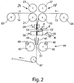
- the clamping device 29 and the clamping holding device 35 are preferably closed at the same time, preferably with a movement according to arrow A, so that the first and second film composite are clamped to one another in the respective working gap 31 ( Figure 2 ).
- the cutting device 38 is then activated.
- a cutting knife can be moved according to arrow B.
- the first and second film composite 14, 15 are separated by the cutting device 38 and a joint 53 is formed.
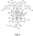
- a vacuum is applied to the clamping blocks 36.
- the joint 53 formed between the first and second film composite 14, 15 is supplied to the connecting station 44 in a supportive manner by the guide plates 41.
- the connecting elements 49 can each be attached, in particular glued, to the end 52 of the first film composite 14 and the beginning 51 of the second film composite 15, bridging the joint 53. This is in Figure 5 shown.
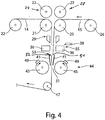
- the guide roller 27 and the vacuum rollers 45 of the connection station 44 continue to be driven synchronously, and the connection point 61, which connects the first and second film composite 14, 15, is led out of the splicing device 11.
- the supply roll 22 of the first film composite 14 can be wound up so that the remaining second end 55 of the first film composite 14 ( Figure 5 ) is led out of the splicing device 11 in order to subsequently change the supply roll with a new film composite.
- the subsequent splicing is carried out in mirror image to the previously described work steps Figures 1 to 5 .
- connection point 61 a schematic sectional view of the connection point 61 is shown, which is produced with the connection station 44.
- An end 52 of the first film composite 14 is connected to the start 51 of the second film composite 15 by this connection point 61.
- the film composite 14, 15 is preferably constructed in three layers. This comprises a carrier layer 62 on which a polymer layer 63 is applied.
- This polymer layer 63 can be a photopolymer, in particular a polymer layer with holograms incorporated therein. This polymer layer 63 is protected from damage by a protective layer 64.
- This splicing device 11 has the advantage that such triple assemblies are connected to one another by simply stringing them together. It is not necessary to detach the protective and / or carrier layer on one or both sides to connect the middle polymer layer.
- This splicing device 11 can also process a single-layer web material or a multi-layer film composite in a departure from the triple composite shown. ⁇ b> List of reference numbers ⁇ /b> 11.
- Splicer 35 Clamping device 59. 12. 36. Terminal blocks 60. 13. 37. 61. Liaison office 14.
Landscapes
- Engineering & Computer Science (AREA)
- Mechanical Engineering (AREA)
- Replacement Of Web Rolls (AREA)
- Lining Or Joining Of Plastics Or The Like (AREA)
Applications Claiming Priority (1)
| Application Number | Priority Date | Filing Date | Title |
|---|---|---|---|
| DE102018130674.1A DE102018130674B4 (de) | 2018-12-03 | 2018-12-03 | Verfahren und Vorrichtung zum Spleißen von einem ersten und einem zweiten Folienverbund |
Publications (2)
| Publication Number | Publication Date |
|---|---|
| EP3663243A1 true EP3663243A1 (fr) | 2020-06-10 |
| EP3663243B1 EP3663243B1 (fr) | 2023-09-06 |
Family
ID=68762538
Family Applications (1)
| Application Number | Title | Priority Date | Filing Date |
|---|---|---|---|
| EP19212787.6A Active EP3663243B1 (fr) | 2018-12-03 | 2019-12-02 | Procédé et dispositif d'épissure d'un premier et d'un deuxième films composites |
Country Status (2)
| Country | Link |
|---|---|
| EP (1) | EP3663243B1 (fr) |
| DE (1) | DE102018130674B4 (fr) |
Cited By (6)
| Publication number | Priority date | Publication date | Assignee | Title |
|---|---|---|---|---|
| CN113103728A (zh) * | 2021-05-19 | 2021-07-13 | 上海紫江彩印包装有限公司 | 一种易撕复合膜的在线制备方法、系统装置及其制备的复合膜 |
| CN115416317A (zh) * | 2022-09-06 | 2022-12-02 | 深圳鑫富艺科技股份有限公司 | 一种bp膜和cop膜拼接设备及拼接工艺方法 |
| WO2023116842A1 (fr) * | 2021-12-22 | 2023-06-29 | 软控股份有限公司 | Dispositif d'alimentation automatique en bande de caoutchouc |
| CN116902647A (zh) * | 2023-06-02 | 2023-10-20 | 宁波晶天塑胶科技有限公司 | 一种复合包装膜加工工艺及其加工设备 |
| WO2025066267A1 (fr) * | 2023-09-28 | 2025-04-03 | 宁德时代新能源科技股份有限公司 | Appareil de coupe et de jonction, système de revêtement par film et procédé de coupe et de jonction de bande de matériau |
| WO2026012669A1 (fr) * | 2024-07-12 | 2026-01-15 | Mb Automation Gmbh & Co. Kg | Appareil et procédé de raccordement de bandes d'au moins des bandes de matériaux bicouches |
Citations (3)
| Publication number | Priority date | Publication date | Assignee | Title |
|---|---|---|---|---|
| US5698060A (en) * | 1995-12-14 | 1997-12-16 | Eastman Kodak Company | Web butt-splicing apparatus |
| DE19962413A1 (de) | 1999-12-22 | 2001-06-28 | Kiener Maschinenbau Gmbh | Verfahren und Vorrichtung zum Herstellen eines zumindest eine Polymerfolie mit Informationen und zumindest eine Trägerschicht enthaltenden Verbundes zur Weiterverarbeitung für fälschungssichere Dokumente |
| US20070044898A1 (en) * | 2005-08-31 | 2007-03-01 | Fuji Photo Film Co., Ltd. | Apparatus and method for matching and splicing webs |
Family Cites Families (8)
| Publication number | Priority date | Publication date | Assignee | Title |
|---|---|---|---|---|
| JPS5329174B2 (fr) | 1973-11-29 | 1978-08-18 | ||
| FR2679888B1 (fr) | 1991-08-02 | 1993-11-26 | Du Pont De Nemours And Cy | Procede et dispositif pour raccorder en continuite deux feuils minces. |
| DE69941094D1 (de) | 1999-02-03 | 2009-08-20 | Goodyear Tire & Rubber | Stossverbinden von gummibahnen |
| US6533891B1 (en) | 1999-02-03 | 2003-03-18 | The Goodyear Tire & Rubber Company | Butt splicing of elastomeric sheets |
| DE10226148B4 (de) | 2002-06-13 | 2011-11-17 | Tetra Laval Holdings & Finance S.A. | Vorrichtung zum Verkleben zweier Verpackungsmaterialbahnen |
| US7073552B2 (en) | 2002-12-20 | 2006-07-11 | The Goodyear Tire & Rubber Company | Tire preparation ply manufacturing apparatus and method |
| DE102011111786A1 (de) | 2011-09-01 | 2013-03-07 | Ovd Kinegram Ag | Verfahren und Vorrichtung zum Verbinden von Transfer- oder Laminierfolienbahnen |
| DE102015210522A1 (de) | 2015-06-09 | 2016-12-15 | Bundesdruckerei Gmbh | Verfahren und Vorrichtung zum Herstellen eines Sicherheitselemente aufweisenden mehrlagigen Wert- oder Sicherheitsdokuments |
-
2018
- 2018-12-03 DE DE102018130674.1A patent/DE102018130674B4/de active Active
-
2019
- 2019-12-02 EP EP19212787.6A patent/EP3663243B1/fr active Active
Patent Citations (3)
| Publication number | Priority date | Publication date | Assignee | Title |
|---|---|---|---|---|
| US5698060A (en) * | 1995-12-14 | 1997-12-16 | Eastman Kodak Company | Web butt-splicing apparatus |
| DE19962413A1 (de) | 1999-12-22 | 2001-06-28 | Kiener Maschinenbau Gmbh | Verfahren und Vorrichtung zum Herstellen eines zumindest eine Polymerfolie mit Informationen und zumindest eine Trägerschicht enthaltenden Verbundes zur Weiterverarbeitung für fälschungssichere Dokumente |
| US20070044898A1 (en) * | 2005-08-31 | 2007-03-01 | Fuji Photo Film Co., Ltd. | Apparatus and method for matching and splicing webs |
Cited By (7)
| Publication number | Priority date | Publication date | Assignee | Title |
|---|---|---|---|---|
| CN113103728A (zh) * | 2021-05-19 | 2021-07-13 | 上海紫江彩印包装有限公司 | 一种易撕复合膜的在线制备方法、系统装置及其制备的复合膜 |
| WO2023116842A1 (fr) * | 2021-12-22 | 2023-06-29 | 软控股份有限公司 | Dispositif d'alimentation automatique en bande de caoutchouc |
| CN115416317A (zh) * | 2022-09-06 | 2022-12-02 | 深圳鑫富艺科技股份有限公司 | 一种bp膜和cop膜拼接设备及拼接工艺方法 |
| CN116902647A (zh) * | 2023-06-02 | 2023-10-20 | 宁波晶天塑胶科技有限公司 | 一种复合包装膜加工工艺及其加工设备 |
| CN116902647B (zh) * | 2023-06-02 | 2024-05-03 | 临沂驰禾塑料制品有限公司 | 一种复合包装膜加工工艺及其加工设备 |
| WO2025066267A1 (fr) * | 2023-09-28 | 2025-04-03 | 宁德时代新能源科技股份有限公司 | Appareil de coupe et de jonction, système de revêtement par film et procédé de coupe et de jonction de bande de matériau |
| WO2026012669A1 (fr) * | 2024-07-12 | 2026-01-15 | Mb Automation Gmbh & Co. Kg | Appareil et procédé de raccordement de bandes d'au moins des bandes de matériaux bicouches |
Also Published As
| Publication number | Publication date |
|---|---|
| DE102018130674B4 (de) | 2021-12-23 |
| EP3663243B1 (fr) | 2023-09-06 |
| DE102018130674A1 (de) | 2020-06-04 |
Similar Documents
| Publication | Publication Date | Title |
|---|---|---|
| EP3663243B1 (fr) | Procédé et dispositif d'épissure d'un premier et d'un deuxième films composites | |
| DE3751754T2 (de) | Vorrichtung zum Befestigen einer Ersatzbahn an einer Bahn, die eine programmierte Bewegung durchführt, ohne eine solche Bewegung zu unterbrechen | |
| DE2107677B2 (de) | Vorrichtung zum stampfen Verbinden des Hinterendes eines auslaufenden Bahnmaterials mit dem Vorderende eines neuen Bahnmaterials | |
| DE3811138A1 (de) | Verfahren und vorrichtung zum behandeln des endabschnitts von aufgerolltem papier | |
| DE3536509A1 (de) | Verfahren und vorrichtung zum einbringen von compact-discs (cd) in cd-boxen | |
| DE4139586C2 (de) | Verfahren und Vorrichtung zum Bilden und Erfassen eines Bahnanfanges einer Ersatz-Wickelrolle | |
| DE3244966C1 (de) | Verfahren und Trenneinrichtung zum Durchtrennen von bahnfoermigem Zellstoff beim Anwickeln auf Wickelhuelsen | |
| EP3416905B1 (fr) | Procédé et dispositif d'obtention d'une feuille séparée dans un dispositif d'impression | |
| DE69606448T2 (de) | Abwickelvorrichtung für bandförmiges Material | |
| DE2751862A1 (de) | Verfahren und vorrichtung zum abstreifen und entwickeln eines lichtempfindlichen materials | |
| EP1749590B1 (fr) | Procédé d'application d'adhésifs sur une liaison entre deux bandes et applicateur de ruban adhésif | |
| EP0299180A2 (fr) | Dispositif de déroulage pour bande de papier ou de carton | |
| DE2256364C2 (de) | Klebegerät | |
| DE69112646T2 (de) | Verfahren und vorrichtung zur herstellung von etiketten. | |
| DE69230396T2 (de) | Verfahren und Vorrichtung zum Beschichten von Filmen | |
| WO2024028168A1 (fr) | Dispositif et procédé de raccordement de bandes de matériau continues | |
| DE3203644A1 (de) | Verfahren und vorrichtung zum automatischen spleissen bzw. verbinden von folien | |
| DE2805076A1 (de) | Vorrichtung zum spleissen zweier streifen | |
| DE3503715C2 (fr) | ||
| DE102014211818A1 (de) | Verfahren zum Herstellen eines Kabels mit einer flexiblen Hülse, insbesondere einer Markierungshülse, und Kabelmarkiervorrichtung | |
| EP3556556A1 (fr) | Dispositif de revêtement | |
| DE102023125195A1 (de) | Vorrichtung zum Verbinden von Etikettenbändern | |
| EP0368027A2 (fr) | Méthode et dispositif de fabrication de produits stratifiés en partant de bandes autocollantes | |
| DE102022125536A1 (de) | Vorrichtung zum Verbinden von Materialbahnen für die Herstellung von Energiezellen | |
| DE102022125535A1 (de) | Vorrichtung und Verfahren zum Verbinden von Materialbahnen für die Herstellung von Energiezellen |
Legal Events
| Date | Code | Title | Description |
|---|---|---|---|
| PUAI | Public reference made under article 153(3) epc to a published international application that has entered the european phase |
Free format text: ORIGINAL CODE: 0009012 |
|
| STAA | Information on the status of an ep patent application or granted ep patent |
Free format text: STATUS: THE APPLICATION HAS BEEN PUBLISHED |
|
| AK | Designated contracting states |
Kind code of ref document: A1 Designated state(s): AL AT BE BG CH CY CZ DE DK EE ES FI FR GB GR HR HU IE IS IT LI LT LU LV MC MK MT NL NO PL PT RO RS SE SI SK SM TR |
|
| AX | Request for extension of the european patent |
Extension state: BA ME |
|
| STAA | Information on the status of an ep patent application or granted ep patent |
Free format text: STATUS: REQUEST FOR EXAMINATION WAS MADE |
|
| 17P | Request for examination filed |
Effective date: 20201210 |
|
| RBV | Designated contracting states (corrected) |
Designated state(s): AL AT BE BG CH CY CZ DE DK EE ES FI FR GB GR HR HU IE IS IT LI LT LU LV MC MK MT NL NO PL PT RO RS SE SI SK SM TR |
|
| RIC1 | Information provided on ipc code assigned before grant |
Ipc: B29C 65/50 20060101ALI20220820BHEP Ipc: B29C 65/00 20060101ALI20220820BHEP Ipc: B29C 65/78 20060101ALI20220820BHEP Ipc: B65H 19/18 20060101AFI20220820BHEP |
|
| GRAP | Despatch of communication of intention to grant a patent |
Free format text: ORIGINAL CODE: EPIDOSNIGR1 |
|
| STAA | Information on the status of an ep patent application or granted ep patent |
Free format text: STATUS: GRANT OF PATENT IS INTENDED |
|
| INTG | Intention to grant announced |
Effective date: 20221202 |
|
| GRAJ | Information related to disapproval of communication of intention to grant by the applicant or resumption of examination proceedings by the epo deleted |
Free format text: ORIGINAL CODE: EPIDOSDIGR1 |
|
| STAA | Information on the status of an ep patent application or granted ep patent |
Free format text: STATUS: REQUEST FOR EXAMINATION WAS MADE |
|
| INTC | Intention to grant announced (deleted) | ||
| P01 | Opt-out of the competence of the unified patent court (upc) registered |
Effective date: 20230526 |
|
| GRAP | Despatch of communication of intention to grant a patent |
Free format text: ORIGINAL CODE: EPIDOSNIGR1 |
|
| STAA | Information on the status of an ep patent application or granted ep patent |
Free format text: STATUS: GRANT OF PATENT IS INTENDED |
|
| GRAS | Grant fee paid |
Free format text: ORIGINAL CODE: EPIDOSNIGR3 |
|
| INTG | Intention to grant announced |
Effective date: 20230707 |
|
| GRAA | (expected) grant |
Free format text: ORIGINAL CODE: 0009210 |
|
| STAA | Information on the status of an ep patent application or granted ep patent |
Free format text: STATUS: THE PATENT HAS BEEN GRANTED |
|
| AK | Designated contracting states |
Kind code of ref document: B1 Designated state(s): AL AT BE BG CH CY CZ DE DK EE ES FI FR GB GR HR HU IE IS IT LI LT LU LV MC MK MT NL NO PL PT RO RS SE SI SK SM TR |
|
| REG | Reference to a national code |
Ref country code: GB Ref legal event code: FG4D Free format text: NOT ENGLISH |
|
| REG | Reference to a national code |
Ref country code: CH Ref legal event code: EP |
|
| REG | Reference to a national code |
Ref country code: IE Ref legal event code: FG4D Free format text: LANGUAGE OF EP DOCUMENT: GERMAN |
|
| REG | Reference to a national code |
Ref country code: DE Ref legal event code: R096 Ref document number: 502019009239 Country of ref document: DE |
|
| REG | Reference to a national code |
Ref country code: LT Ref legal event code: MG9D |
|
| REG | Reference to a national code |
Ref country code: NL Ref legal event code: MP Effective date: 20230906 |
|
| PG25 | Lapsed in a contracting state [announced via postgrant information from national office to epo] |
Ref country code: GR Free format text: LAPSE BECAUSE OF FAILURE TO SUBMIT A TRANSLATION OF THE DESCRIPTION OR TO PAY THE FEE WITHIN THE PRESCRIBED TIME-LIMIT Effective date: 20231207 |
|
| PG25 | Lapsed in a contracting state [announced via postgrant information from national office to epo] |
Ref country code: SE Free format text: LAPSE BECAUSE OF FAILURE TO SUBMIT A TRANSLATION OF THE DESCRIPTION OR TO PAY THE FEE WITHIN THE PRESCRIBED TIME-LIMIT Effective date: 20230906 Ref country code: RS Free format text: LAPSE BECAUSE OF FAILURE TO SUBMIT A TRANSLATION OF THE DESCRIPTION OR TO PAY THE FEE WITHIN THE PRESCRIBED TIME-LIMIT Effective date: 20230906 Ref country code: NO Free format text: LAPSE BECAUSE OF FAILURE TO SUBMIT A TRANSLATION OF THE DESCRIPTION OR TO PAY THE FEE WITHIN THE PRESCRIBED TIME-LIMIT Effective date: 20231206 Ref country code: LV Free format text: LAPSE BECAUSE OF FAILURE TO SUBMIT A TRANSLATION OF THE DESCRIPTION OR TO PAY THE FEE WITHIN THE PRESCRIBED TIME-LIMIT Effective date: 20230906 Ref country code: LT Free format text: LAPSE BECAUSE OF FAILURE TO SUBMIT A TRANSLATION OF THE DESCRIPTION OR TO PAY THE FEE WITHIN THE PRESCRIBED TIME-LIMIT Effective date: 20230906 Ref country code: HR Free format text: LAPSE BECAUSE OF FAILURE TO SUBMIT A TRANSLATION OF THE DESCRIPTION OR TO PAY THE FEE WITHIN THE PRESCRIBED TIME-LIMIT Effective date: 20230906 Ref country code: GR Free format text: LAPSE BECAUSE OF FAILURE TO SUBMIT A TRANSLATION OF THE DESCRIPTION OR TO PAY THE FEE WITHIN THE PRESCRIBED TIME-LIMIT Effective date: 20231207 Ref country code: FI Free format text: LAPSE BECAUSE OF FAILURE TO SUBMIT A TRANSLATION OF THE DESCRIPTION OR TO PAY THE FEE WITHIN THE PRESCRIBED TIME-LIMIT Effective date: 20230906 |
|
| PG25 | Lapsed in a contracting state [announced via postgrant information from national office to epo] |
Ref country code: NL Free format text: LAPSE BECAUSE OF FAILURE TO SUBMIT A TRANSLATION OF THE DESCRIPTION OR TO PAY THE FEE WITHIN THE PRESCRIBED TIME-LIMIT Effective date: 20230906 |
|
| PG25 | Lapsed in a contracting state [announced via postgrant information from national office to epo] |
Ref country code: IS Free format text: LAPSE BECAUSE OF FAILURE TO SUBMIT A TRANSLATION OF THE DESCRIPTION OR TO PAY THE FEE WITHIN THE PRESCRIBED TIME-LIMIT Effective date: 20240106 |
|
| PG25 | Lapsed in a contracting state [announced via postgrant information from national office to epo] |
Ref country code: ES Free format text: LAPSE BECAUSE OF FAILURE TO SUBMIT A TRANSLATION OF THE DESCRIPTION OR TO PAY THE FEE WITHIN THE PRESCRIBED TIME-LIMIT Effective date: 20230906 |
|
| PG25 | Lapsed in a contracting state [announced via postgrant information from national office to epo] |
Ref country code: SM Free format text: LAPSE BECAUSE OF FAILURE TO SUBMIT A TRANSLATION OF THE DESCRIPTION OR TO PAY THE FEE WITHIN THE PRESCRIBED TIME-LIMIT Effective date: 20230906 Ref country code: RO Free format text: LAPSE BECAUSE OF FAILURE TO SUBMIT A TRANSLATION OF THE DESCRIPTION OR TO PAY THE FEE WITHIN THE PRESCRIBED TIME-LIMIT Effective date: 20230906 Ref country code: IS Free format text: LAPSE BECAUSE OF FAILURE TO SUBMIT A TRANSLATION OF THE DESCRIPTION OR TO PAY THE FEE WITHIN THE PRESCRIBED TIME-LIMIT Effective date: 20240106 Ref country code: ES Free format text: LAPSE BECAUSE OF FAILURE TO SUBMIT A TRANSLATION OF THE DESCRIPTION OR TO PAY THE FEE WITHIN THE PRESCRIBED TIME-LIMIT Effective date: 20230906 Ref country code: EE Free format text: LAPSE BECAUSE OF FAILURE TO SUBMIT A TRANSLATION OF THE DESCRIPTION OR TO PAY THE FEE WITHIN THE PRESCRIBED TIME-LIMIT Effective date: 20230906 Ref country code: CZ Free format text: LAPSE BECAUSE OF FAILURE TO SUBMIT A TRANSLATION OF THE DESCRIPTION OR TO PAY THE FEE WITHIN THE PRESCRIBED TIME-LIMIT Effective date: 20230906 Ref country code: SK Free format text: LAPSE BECAUSE OF FAILURE TO SUBMIT A TRANSLATION OF THE DESCRIPTION OR TO PAY THE FEE WITHIN THE PRESCRIBED TIME-LIMIT Effective date: 20230906 Ref country code: PT Free format text: LAPSE BECAUSE OF FAILURE TO SUBMIT A TRANSLATION OF THE DESCRIPTION OR TO PAY THE FEE WITHIN THE PRESCRIBED TIME-LIMIT Effective date: 20240108 |
|
| PG25 | Lapsed in a contracting state [announced via postgrant information from national office to epo] |
Ref country code: PL Free format text: LAPSE BECAUSE OF FAILURE TO SUBMIT A TRANSLATION OF THE DESCRIPTION OR TO PAY THE FEE WITHIN THE PRESCRIBED TIME-LIMIT Effective date: 20230906 Ref country code: IT Free format text: LAPSE BECAUSE OF FAILURE TO SUBMIT A TRANSLATION OF THE DESCRIPTION OR TO PAY THE FEE WITHIN THE PRESCRIBED TIME-LIMIT Effective date: 20230906 |
|
| REG | Reference to a national code |
Ref country code: DE Ref legal event code: R097 Ref document number: 502019009239 Country of ref document: DE |
|
| PG25 | Lapsed in a contracting state [announced via postgrant information from national office to epo] |
Ref country code: DK Free format text: LAPSE BECAUSE OF FAILURE TO SUBMIT A TRANSLATION OF THE DESCRIPTION OR TO PAY THE FEE WITHIN THE PRESCRIBED TIME-LIMIT Effective date: 20230906 |
|
| PLBE | No opposition filed within time limit |
Free format text: ORIGINAL CODE: 0009261 |
|
| STAA | Information on the status of an ep patent application or granted ep patent |
Free format text: STATUS: NO OPPOSITION FILED WITHIN TIME LIMIT |
|
| PG25 | Lapsed in a contracting state [announced via postgrant information from national office to epo] |
Ref country code: DK Free format text: LAPSE BECAUSE OF FAILURE TO SUBMIT A TRANSLATION OF THE DESCRIPTION OR TO PAY THE FEE WITHIN THE PRESCRIBED TIME-LIMIT Effective date: 20230906 Ref country code: SI Free format text: LAPSE BECAUSE OF FAILURE TO SUBMIT A TRANSLATION OF THE DESCRIPTION OR TO PAY THE FEE WITHIN THE PRESCRIBED TIME-LIMIT Effective date: 20230906 |
|
| REG | Reference to a national code |
Ref country code: CH Ref legal event code: PL |
|
| 26N | No opposition filed |
Effective date: 20240607 |
|
| PG25 | Lapsed in a contracting state [announced via postgrant information from national office to epo] |
Ref country code: LU Free format text: LAPSE BECAUSE OF NON-PAYMENT OF DUE FEES Effective date: 20231202 |
|
| PG25 | Lapsed in a contracting state [announced via postgrant information from national office to epo] |
Ref country code: MC Free format text: LAPSE BECAUSE OF FAILURE TO SUBMIT A TRANSLATION OF THE DESCRIPTION OR TO PAY THE FEE WITHIN THE PRESCRIBED TIME-LIMIT Effective date: 20230906 |
|
| REG | Reference to a national code |
Ref country code: BE Ref legal event code: MM Effective date: 20231231 |
|
| PG25 | Lapsed in a contracting state [announced via postgrant information from national office to epo] |
Ref country code: MC Free format text: LAPSE BECAUSE OF FAILURE TO SUBMIT A TRANSLATION OF THE DESCRIPTION OR TO PAY THE FEE WITHIN THE PRESCRIBED TIME-LIMIT Effective date: 20230906 Ref country code: LU Free format text: LAPSE BECAUSE OF NON-PAYMENT OF DUE FEES Effective date: 20231202 |
|
| REG | Reference to a national code |
Ref country code: IE Ref legal event code: MM4A |
|
| PG25 | Lapsed in a contracting state [announced via postgrant information from national office to epo] |
Ref country code: IE Free format text: LAPSE BECAUSE OF NON-PAYMENT OF DUE FEES Effective date: 20231202 |
|
| PG25 | Lapsed in a contracting state [announced via postgrant information from national office to epo] |
Ref country code: BE Free format text: LAPSE BECAUSE OF NON-PAYMENT OF DUE FEES Effective date: 20231231 |
|
| PG25 | Lapsed in a contracting state [announced via postgrant information from national office to epo] |
Ref country code: CH Free format text: LAPSE BECAUSE OF NON-PAYMENT OF DUE FEES Effective date: 20231231 |
|
| PG25 | Lapsed in a contracting state [announced via postgrant information from national office to epo] |
Ref country code: IE Free format text: LAPSE BECAUSE OF NON-PAYMENT OF DUE FEES Effective date: 20231202 Ref country code: CH Free format text: LAPSE BECAUSE OF NON-PAYMENT OF DUE FEES Effective date: 20231231 Ref country code: BE Free format text: LAPSE BECAUSE OF NON-PAYMENT OF DUE FEES Effective date: 20231231 |
|
| PG25 | Lapsed in a contracting state [announced via postgrant information from national office to epo] |
Ref country code: BG Free format text: LAPSE BECAUSE OF FAILURE TO SUBMIT A TRANSLATION OF THE DESCRIPTION OR TO PAY THE FEE WITHIN THE PRESCRIBED TIME-LIMIT Effective date: 20230906 |
|
| PG25 | Lapsed in a contracting state [announced via postgrant information from national office to epo] |
Ref country code: BG Free format text: LAPSE BECAUSE OF FAILURE TO SUBMIT A TRANSLATION OF THE DESCRIPTION OR TO PAY THE FEE WITHIN THE PRESCRIBED TIME-LIMIT Effective date: 20230906 |
|
| PG25 | Lapsed in a contracting state [announced via postgrant information from national office to epo] |
Ref country code: CY Free format text: LAPSE BECAUSE OF FAILURE TO SUBMIT A TRANSLATION OF THE DESCRIPTION OR TO PAY THE FEE WITHIN THE PRESCRIBED TIME-LIMIT; INVALID AB INITIO Effective date: 20191202 |
|
| PG25 | Lapsed in a contracting state [announced via postgrant information from national office to epo] |
Ref country code: HU Free format text: LAPSE BECAUSE OF FAILURE TO SUBMIT A TRANSLATION OF THE DESCRIPTION OR TO PAY THE FEE WITHIN THE PRESCRIBED TIME-LIMIT; INVALID AB INITIO Effective date: 20191202 |
|
| PG25 | Lapsed in a contracting state [announced via postgrant information from national office to epo] |
Ref country code: TR Free format text: LAPSE BECAUSE OF FAILURE TO SUBMIT A TRANSLATION OF THE DESCRIPTION OR TO PAY THE FEE WITHIN THE PRESCRIBED TIME-LIMIT Effective date: 20230906 |
|
| PGFP | Annual fee paid to national office [announced via postgrant information from national office to epo] |
Ref country code: GB Payment date: 20251218 Year of fee payment: 7 |
|
| PGFP | Annual fee paid to national office [announced via postgrant information from national office to epo] |
Ref country code: FR Payment date: 20251217 Year of fee payment: 7 |
|
| REG | Reference to a national code |
Ref country code: AT Ref legal event code: MM01 Ref document number: 1608315 Country of ref document: AT Kind code of ref document: T Effective date: 20241202 |
|
| PGFP | Annual fee paid to national office [announced via postgrant information from national office to epo] |
Ref country code: DE Payment date: 20251222 Year of fee payment: 7 |
|
| PG25 | Lapsed in a contracting state [announced via postgrant information from national office to epo] |
Ref country code: AT Free format text: LAPSE BECAUSE OF NON-PAYMENT OF DUE FEES Effective date: 20241202 |
|
| PGFP | Annual fee paid to national office [announced via postgrant information from national office to epo] |
Ref country code: AT Payment date: 20260410 Year of fee payment: 5 |