EP3662749A1 - Device for discharging flowable material and method for operating a device for discharging flowable material - Google Patents
Device for discharging flowable material and method for operating a device for discharging flowable material Download PDFInfo
- Publication number
- EP3662749A1 EP3662749A1 EP19213722.2A EP19213722A EP3662749A1 EP 3662749 A1 EP3662749 A1 EP 3662749A1 EP 19213722 A EP19213722 A EP 19213722A EP 3662749 A1 EP3662749 A1 EP 3662749A1
- Authority
- EP
- European Patent Office
- Prior art keywords
- spray
- devices
- spraying
- carrier
- actuating
- Prior art date
- Legal status (The legal status is an assumption and is not a legal conclusion. Google has not performed a legal analysis and makes no representation as to the accuracy of the status listed.)
- Granted
Links
- 230000009969 flowable effect Effects 0.000 title claims abstract description 23
- 238000000034 method Methods 0.000 title claims description 6
- 239000000463 material Substances 0.000 title description 5
- 238000007599 discharging Methods 0.000 title 2
- 239000007921 spray Substances 0.000 claims abstract description 103
- 238000005507 spraying Methods 0.000 claims abstract description 26
- 239000011814 protection agent Substances 0.000 claims abstract description 11
- 230000008878 coupling Effects 0.000 claims description 12
- 238000010168 coupling process Methods 0.000 claims description 12
- 238000005859 coupling reaction Methods 0.000 claims description 12
- 241000196324 Embryophyta Species 0.000 description 13
- 239000003795 chemical substances by application Substances 0.000 description 5
- 238000006073 displacement reaction Methods 0.000 description 3
- 239000007788 liquid Substances 0.000 description 3
- 238000011282 treatment Methods 0.000 description 3
- 244000188595 Brassica sinapistrum Species 0.000 description 1
- 235000004977 Brassica sinapistrum Nutrition 0.000 description 1
- 230000009286 beneficial effect Effects 0.000 description 1
- 230000000903 blocking effect Effects 0.000 description 1
- 230000001419 dependent effect Effects 0.000 description 1
- 238000011161 development Methods 0.000 description 1
- 230000018109 developmental process Effects 0.000 description 1
- 230000000694 effects Effects 0.000 description 1
- 239000003337 fertilizer Substances 0.000 description 1
- 238000001746 injection moulding Methods 0.000 description 1
- 239000002917 insecticide Substances 0.000 description 1
- 239000002184 metal Substances 0.000 description 1
- 239000000575 pesticide Substances 0.000 description 1
- 239000004476 plant protection product Substances 0.000 description 1
- 230000001105 regulatory effect Effects 0.000 description 1
- 230000009528 severe injury Effects 0.000 description 1
- 239000000243 solution Substances 0.000 description 1
Images
Classifications
-
- A—HUMAN NECESSITIES
- A01—AGRICULTURE; FORESTRY; ANIMAL HUSBANDRY; HUNTING; TRAPPING; FISHING
- A01M—CATCHING, TRAPPING OR SCARING OF ANIMALS; APPARATUS FOR THE DESTRUCTION OF NOXIOUS ANIMALS OR NOXIOUS PLANTS
- A01M7/00—Special adaptations or arrangements of liquid-spraying apparatus for purposes covered by this subclass
- A01M7/005—Special arrangements or adaptations of the spraying or distributing parts, e.g. adaptations or mounting of the spray booms, mounting of the nozzles, protection shields
- A01M7/006—Mounting of the nozzles
-
- A—HUMAN NECESSITIES
- A01—AGRICULTURE; FORESTRY; ANIMAL HUSBANDRY; HUNTING; TRAPPING; FISHING
- A01C—PLANTING; SOWING; FERTILISING
- A01C23/00—Distributing devices specially adapted for liquid manure or other fertilising liquid, including ammonia, e.g. transport tanks or sprinkling wagons
- A01C23/008—Tanks, chassis or related parts
-
- A—HUMAN NECESSITIES
- A01—AGRICULTURE; FORESTRY; ANIMAL HUSBANDRY; HUNTING; TRAPPING; FISHING
- A01C—PLANTING; SOWING; FERTILISING
- A01C23/00—Distributing devices specially adapted for liquid manure or other fertilising liquid, including ammonia, e.g. transport tanks or sprinkling wagons
- A01C23/04—Distributing under pressure; Distributing mud; Adaptation of watering systems for fertilising-liquids
- A01C23/047—Spraying of liquid fertilisers
-
- A—HUMAN NECESSITIES
- A01—AGRICULTURE; FORESTRY; ANIMAL HUSBANDRY; HUNTING; TRAPPING; FISHING
- A01M—CATCHING, TRAPPING OR SCARING OF ANIMALS; APPARATUS FOR THE DESTRUCTION OF NOXIOUS ANIMALS OR NOXIOUS PLANTS
- A01M7/00—Special adaptations or arrangements of liquid-spraying apparatus for purposes covered by this subclass
- A01M7/0025—Mechanical sprayers
- A01M7/0032—Pressure sprayers
- A01M7/0042—Field sprayers, e.g. self-propelled, drawn or tractor-mounted
-
- A—HUMAN NECESSITIES
- A01—AGRICULTURE; FORESTRY; ANIMAL HUSBANDRY; HUNTING; TRAPPING; FISHING
- A01M—CATCHING, TRAPPING OR SCARING OF ANIMALS; APPARATUS FOR THE DESTRUCTION OF NOXIOUS ANIMALS OR NOXIOUS PLANTS
- A01M7/00—Special adaptations or arrangements of liquid-spraying apparatus for purposes covered by this subclass
- A01M7/005—Special arrangements or adaptations of the spraying or distributing parts, e.g. adaptations or mounting of the spray booms, mounting of the nozzles, protection shields
- A01M7/0071—Construction of the spray booms
- A01M7/0075—Construction of the spray booms including folding means
-
- A—HUMAN NECESSITIES
- A01—AGRICULTURE; FORESTRY; ANIMAL HUSBANDRY; HUNTING; TRAPPING; FISHING
- A01M—CATCHING, TRAPPING OR SCARING OF ANIMALS; APPARATUS FOR THE DESTRUCTION OF NOXIOUS ANIMALS OR NOXIOUS PLANTS
- A01M7/00—Special adaptations or arrangements of liquid-spraying apparatus for purposes covered by this subclass
- A01M7/0082—Undercarriages, frames, mountings, couplings, tanks
-
- B—PERFORMING OPERATIONS; TRANSPORTING
- B05—SPRAYING OR ATOMISING IN GENERAL; APPLYING FLUENT MATERIALS TO SURFACES, IN GENERAL
- B05B—SPRAYING APPARATUS; ATOMISING APPARATUS; NOZZLES
- B05B15/00—Details of spraying plant or spraying apparatus not otherwise provided for; Accessories
- B05B15/60—Arrangements for mounting, supporting or holding spraying apparatus
- B05B15/65—Mounting arrangements for fluid connection of the spraying apparatus or its outlets to flow conduits
- B05B15/652—Mounting arrangements for fluid connection of the spraying apparatus or its outlets to flow conduits whereby the jet can be oriented
Definitions
- the present invention relates to a device for dispensing flowable media and in particular to a device for dispensing crop protection agents, insecticides and the like.
- flowable that is to say in particular liquid or also gaseous, agents, such as crop protection agents, liquid fertilizers or the like, are applied to plants.
- spray rods are known, for which the Dropleg® brand name is also used by the applicant.
- Such spray bars have a tubular body, which is used to guide the respective agent to be applied, and an application device, such as a nozzle, which applies the agent to the plants.
- Such spray bars are arranged, for example, next to one another on a carrier and can thus be transported through the individual rows of the respective plant material. If a repositioning is necessary, for example if a further row is to be loaded, it is common in the prior art that these rods are dismantled and then reassembled in a new position. However, this procedure is relatively complex. Particularly when treating the underblosses, for example of rapeseed, there are increasing demands on crop protection.
- the above-mentioned rods are used, which do not spray in the flower area of the plants and guarantee a high level of bee protection. If the farmer has to drive in a new row, the boom must also be folded in. As mentioned above, this requires dismantling of the linkage each time. As a result, such a system loses acceptance.
- the syringe may be refilled on site.
- dispensing devices arranged on such rods are connected to one another by cable pulls. In this case, however, it may happen that the movement of the individual dispensing devices is no longer completely free, but that they are each coupled to neighboring dispensing devices. If one of the spreading devices is now strongly deflected, this is transferred to the spreading device guided next to it and this can in turn lead to severe damage to the plants or make the treatments in the row impossible.
- the present invention is therefore based on the object, on the one hand, of facilitating a simplified movement of the dispensing devices into a rest position and, on the other hand, of preventing at least too strong a coupling between the individual rods. According to the invention, these objects are achieved by the subject matter of the independent claims. Advantageous embodiments and further developments are the subject of the dependent claims.
- a device according to the invention for spraying plants with flowable media and in particular with crop protection agents has at least a first spray device and a second spray device, the spray devices each having a tubular conduit device which extends in a predetermined longitudinal direction and which is used to conduct a flowable medium and in particular a pesticide are suitable and determined and the spray devices each have at least one spray head which is in flow connection with the line device assigned to it.
- the spray devices are arranged pivotably on a carrier with respect to a predetermined pivot axis, and the device has an actuating device which enables both the first spray device and the second spray device to be pivoted between a working position and a rest position.
- the individual spray devices in particular the spray devices referred to above as droplegs, are arranged pivotably on a carrier and in particular pivotably in an area so that they can be pivoted or folded from a working mode into a sleep mode.
- the spray devices could also be referred to as application devices which are suitable and intended for applying a flowable medium to plants.
- the flowable medium can preferably be applied at least in the working position of the spray devices.
- transport of the same is preferably possible, and in particular transport between different areas to be sprayed.
- the spray device is in a rest position, its respective spray head is at a higher position (in relation to a vertical direction) than in a working position.
- the spray devices or their tubular line devices are oriented essentially vertically in the rest position, whereby essentially vertical means in particular that the longitudinal directions of the line devices are not more than 20 ° from the exactly vertical orientation, preferably not deviate by more than 15 °, preferably by no more than 10 ° and particularly preferably by no more than 5 °.
- the device has a drive device for the actuating device.
- an electrical or magnetic or also hydraulic drive device would also be conceivable.
- the device has more than two spray devices, preferably more than three and preferably more than 4 spray devices, preferably more than 10 spray devices, preferably more than 20 spray devices and preferably more than 30 spray devices. Particularly preferably, several and particularly preferably all of these spray devices can be pivoted, as mentioned above, in order to be brought from a working position into a rest position.
- the spray devices are made of different materials, for example metal or plastic.
- the spray devices can also be made from several different materials.
- a pivoting movement of the first spray device in at least one pivoting direction is not coupled to the pivoting movement of the second spray device.
- the pivoting movement of the first spraying device is particularly preferably not coupled to the pivoting movement of the second spraying device and / or the first spraying device can be pivoted independently of the second spraying device.
- the spray devices preferably have a certain pivotability, but the pivoting movements are not coupled to one another.
- the first spray device and the second spray device are not coupled to one another.
- the device preferably has a plurality of spray devices. These individual spray devices are advantageously not coupled to one another. In this way, a pivoting movement of the first spray device does not influence the pivoting movement the second spray device and these are preferably completely freely movable with respect to each other.
- the invention thus relates to a unit which makes it possible, in an assembled state, to apply the spray devices at one position, for example a linkage.
- the pivot axis of the spray devices is perpendicular to the longitudinal direction of the line device.
- a longitudinal device of the spray device is particularly preferably located in the swivel plane.
- the swivel plane is also perpendicular to a direction of travel, for example of a tractor which carries the present invention.
- the spray device can be pivoted through an angle which is greater than 10 °, preferably greater than 20 °, preferably greater than 30 ° and preferably greater than 40 °.
- the spray device can be pivoted by a pivot angle which is less than 180 °, preferably less than 160 °, preferably less than 140 °, preferably less than 120 ° and particularly preferably less than 100 ° and preferably less than 90 ° and preferred less than 80 °.
- the actuating device is movable relative to the carrier.
- the actuating device is particularly preferably linearly movable relative to the carrier.
- a distance between the actuating device and the carrier can be changed by moving the actuating device relative to the carrier. It is possible for the carrier to extend in a width direction (which is perpendicular to a direction of travel of a vehicle on which the spray devices are arranged) and for the actuating device to also be perpendicular to this direction.
- This width direction can be a direction that is perpendicular to a direction of movement or direction of travel of a tractor.
- the adjusting device particularly preferably also extends in said width direction.
- the direction in which the adjusting device extends and the width direction and the direction in which the carrier extends are particularly preferably parallel to one another.
- the actuating device is particularly preferably movable in the width direction relative to the carrier.
- a linear translational movement along the linkage or the carrier is particularly preferably carried out. This particularly preferably triggers a lifting movement in height.
- the vertical direction is understood to mean in particular a vertical direction.
- Small lugs or projections can be attached to an upper end of the spraying devices and are carried along by the actuating device.
- the actuating device is designed as a web-like, elongated element.
- the actuating device is connected to the carrier via at least one coupling element and preferably via at least two coupling elements. It is possible that these coupling elements are arranged pivotably on the carrier. In addition, these coupling elements are preferably also pivotally arranged on the actuating device. For example, it can be connecting webs which are connected in an articulated manner both to the carrier and to the actuating device.
- a projection is arranged on at least one spray device, which contacts the actuating device, in particular in at least one position of the actuating device. This projection (at least temporarily or in particular while moving the spraying device from the working position to the rest position) can rest on an upper edge of the adjusting device.
- This projection is advantageously designed as a pin-shaped or rod-shaped body.
- This projection is particularly preferably designed such that there is a rest position of the adjusting device in which there is no contact between the adjusting device and the projection. In this position, the spray devices can therefore pivot freely and in particular are not prevented from pivoting by the actuating device.
- the big advantage is that the spray devices can be moved freely in the culture during use and do not influence each other.
- the displacement unit can be actuated and the spraying devices can be carried along by the lower crossmember, that is to say in particular the actuating device, and can preferably also be applied to the carrier or linkage.
- the entire linkage can be folded up. In this way, the expansion in the width direction can also be reduced.
- the carrier therefore particularly preferably has a first carrier part and a second carrier part which can be pivoted and / or folded with respect to one another.
- a shaft is advantageously provided for this purpose, on which in turn the lugs or projections described above, which are arranged on the spray devices, rest.
- Eccentrically designed actuating devices could also be used, which, for example, can be rotated or pivoted about an axis which runs parallel to the carrier. These actuating devices could each contact the above-mentioned projections in order to achieve the pivoting of the spray devices.
- the projection is arranged on the spray device via a cantilever. In this way, the pivoting movement of the spray device can be simplified.
- the spray device has a connection device in order to connect a supply line for supplying a crop protection agent or generally the flowable medium.
- the connection device can be a coupling element which can be coupled or uncoupled without the aid of tools. This coupling element could be designed, for example, as a plug-in coupling or as a bayonet coupling.
- the device has a feed device and in particular a feed line which feeds the flowable medium to the individual spray devices. It is possible that this supply line supplies several spray devices with the flowable medium.
- connecting lines are provided which connect this feed line to the individual spray devices.
- these connecting lines can be flexible lines, in particular, but not exclusively, hose connections. The flexibility of these hoses can in particular be designed such that they allow the spraying devices to pivot.
- it can be provided between the feed line and the individual spray devices and / or between regulating and / or blocking devices, which is suitable and intended to block or regulate a liquid flow reaching the spray devices.
- regulating and / or blocking devices which is suitable and intended to block or regulate a liquid flow reaching the spray devices.
- flow regulators and / or valves could be provided.
- the drive device for carrying out the movement can be a pneumatic drive means, in particular a drive means which has pneumatic cylinders.
- the spray device and / or also further elements, such as in particular the carrier and / or the actuating device are made of one
- the present invention is further directed to a method for operating a device for spraying plants with flowable media and in particular with plant protection agents (PSM), the flowable medium being applied to the plants in a working position with at least a first spraying device and a second spraying device, wherein the spray devices each have a tubular line device which extends in a predetermined longitudinal direction and which conduct the flowable medium, and wherein the spray devices each have at least one spray head for dispensing the flowable medium, which is in flow connection with the line device assigned to it.
- PSM plant protection agents
- the spray devices for transferring the device are pivoted from the working position into a rest position with respect to a predetermined pivot axis, the spray devices being pivotably arranged on a carrier and with an actuating device pivoting both the first spray device and the second spray device between a working position and the Rest position is carried out.
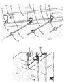
- FIG. 1 shows an illustration of a device 1 according to the invention.
- Reference numeral 6 relates to a carrier which can be mounted, for example, on an agricultural machine, such as a tractor.
- a plurality of spray devices 2, 4 are arranged on this carrier 6. These spray devices can be pivoted here in a plane that is essentially in the plane of the figure.
- Reference numeral 32 indicates a fastening means with which the swivel devices for swiveling the spray device 2, 4 are fastened to the carrier. This fastening means can be fastened to the carrier 6, for example screwed on.
- the reference numerals 24 and 44 each relate to spray heads which are arranged on line devices 22, 42. These line devices can also consist of plastic and have a certain flexibility. It would also be possible for two or more spray heads to be arranged on each line device. In this way, the plants can be supplied with the respective agent at different heights.
- the reference numeral 8 denotes an actuating device which serves to pivot the spray devices 2, 4.
- the spray devices 2, 4 have projections 26, 46 which rest on an upper side of the actuating device 8.
- the reference symbol L denotes a longitudinal direction of the spray devices or their line device.
- the adjusting device 8 can be moved in the direction of the double arrow B, B being the width direction of the support and also the adjusting device at the same time.
- coupling elements or webs are arranged between the carrier 6 and the actuating device 8 via joints 16 and 18. Therefore, moving the actuating device 8 also leads to a raising or lowering of this actuating device and in this way the pivoting process of the spray devices 2, 4 can be initiated.
- Figure 2 shows a representation in which the adjusting device 8 is in the lowest position. It can be seen that here the coupling element 12 is also oriented vertically. In this case, the upper edge 8a does not contact the projections 26 and 46. For this reason, the spray devices 2, 4 can pivot freely and also not coupled to one another.
Landscapes
- Life Sciences & Earth Sciences (AREA)
- Engineering & Computer Science (AREA)
- Environmental Sciences (AREA)
- Insects & Arthropods (AREA)
- Pest Control & Pesticides (AREA)
- Wood Science & Technology (AREA)
- Zoology (AREA)
- Water Supply & Treatment (AREA)
- Soil Sciences (AREA)
- Mechanical Engineering (AREA)
- Catching Or Destruction (AREA)
Abstract
Vorrichtung (1) zum Besprühen von Pflanzen mit fließfähigen Medien und insbesondere mit Pflanzenschutzmitteln (PSM), mit wenigstens einer ersten Sprüheinrichtung (2) und einer zweiten Sprüheinrichtung (4), wobei die Sprüheinrichtungen (2, 4) jeweils eine rohrförmige Leitungseinrichtung (22, 42) aufweisen welche sich in einer vorgegebenen Längsrichtung (L) erstrecken und welche zum Leiten eines fließfähigen Pflanzenschutzmittels geeignet und bestimmt sind und wobei die Sprüheinrichtungen jeweils wenigstens einen Sprühkopf (24. 44) aufweisen, der jeweils mit der ihm zugeordneten Leitungseinrichtung in Strömungsverbindung steht,dadurch gekennzeichnet, dassdie Sprüheinrichtungen (2, 4) schwenkbar bezüglich einer vorgegebenen Schwenkachse (S) an einem Träger (6) angeordnet sind und die Vorrichtung eine Stelleinrichtung (8) aufweist, welche ein Schwenken sowohl der ersten Sprüheinrichtung (2) als auch der zweiten Sprüheinrichtung (4) zwischen einer Arbeitsstellung und einer Ruhestellung erlauben.Device (1) for spraying plants with flowable media and in particular with crop protection agents (PSM), with at least a first spray device (2) and a second spray device (4), the spray devices (2, 4) each having a tubular line device (22, 42) which extend in a predetermined longitudinal direction (L) and which are suitable and intended for conducting a flowable crop protection agent and the spraying devices each have at least one spray head (24.44) which is in flow connection with the line device assigned to it, characterized in that the spray devices (2, 4) are arranged pivotably with respect to a predetermined pivot axis (S) on a carrier (6) and the device has an adjusting device (8) which pivots both the first spray device (2) and the second one Spray device (4) between a working position and a rest position to practice.
Description
Die vorliegende Erfindung bezieht sich auf eine Vorrichtung zum Ausbringen von fließfähigen Medien und insbesondere auf eine Vorrichtung zum Ausbringen von Pflanzenschutzmitteln, Insektiziden und dergleichen. Im Bereich der Landwirtschaft ist es seit Langem bekannt, dass fließfähige, also insbesondere flüssige oder auch gasförmige Mittel, wie beispielsweise Pflanzenschutzmittel, flüssiger Dünger oder dergleichen an Pflanzen ausgebracht werden.The present invention relates to a device for dispensing flowable media and in particular to a device for dispensing crop protection agents, insecticides and the like. In the field of agriculture, it has long been known that flowable, that is to say in particular liquid or also gaseous, agents, such as crop protection agents, liquid fertilizers or the like, are applied to plants.
Bei einigen Anwendungen ist es dabei erforderlich, dass bei vergleichsweise hohen Pflanzen in der Landwirtschaft diese Mittel an untere Bereiche der Pflanzen ausgebracht werden. Zu diesem Zweck sind Sprühgestänge bekannt, für welche durch die Anmelderin auch die Markenbezeichnung Dropleg® verwendet wird.In some applications, it is necessary that in the case of comparatively high plants in agriculture, these agents are applied to lower areas of the plants. For this purpose, spray rods are known, for which the Dropleg® brand name is also used by the applicant.
Diese weisen einen rohrförmigen Körper auf, der zum Leiten des jeweiligen auszubringenden Mittels dient, sowie eine Beaufschlagungseinrichtung, wie beispielsweise eine Düse, welche das Mittel auf die Pflanzen aufbringt. Dabei sind derartige Sprühstangen beispielsweise nebeneinander an einem Träger angeordnet und können so durch die einzelnen Reihen des jeweiligen Pflanzenguts transportiert werden. Wenn eine Umpositionierung erforderlich ist, beispielsweise wenn eine weitere Reihe beaufschlagt werden soll, ist es im Stand der Technik üblich, dass diese Gestänge demontiert und anschließend in einer neuen Position wieder anmontiert werden. Diese Vorgehensweise ist jedoch relativ aufwendig. Insbesondere bei der Unterblütenbehandlung, beispielsweise von Raps, werden immer höhere Anforderungen an den Pflanzenschutz gestellt. Daher werden die oben erwähnten Gestänge eingesetzt, die nicht in dem Blütenbereich der Pflanzen spritzen und einen hohen Bienenschutz garantieren. Muss der Landwirt in eine neue Reihe fahren, muss auch das Gestänge eingeklappt werden. Dies erfordert, wie oben erwähnt, jedes Mal eine Demontage der Gestänge. Hierdurch verliert ein solches System an Akzeptanz.These have a tubular body, which is used to guide the respective agent to be applied, and an application device, such as a nozzle, which applies the agent to the plants. Such spray bars are arranged, for example, next to one another on a carrier and can thus be transported through the individual rows of the respective plant material. If a repositioning is necessary, for example if a further row is to be loaded, it is common in the prior art that these rods are dismantled and then reassembled in a new position. However, this procedure is relatively complex. Particularly when treating the underblosses, for example of rapeseed, there are increasing demands on crop protection. Therefore, the above-mentioned rods are used, which do not spray in the flower area of the plants and guarantee a high level of bee protection. If the farmer has to drive in a new row, the boom must also be folded in. As mentioned above, this requires dismantling of the linkage each time. As a result, such a system loses acceptance.
Der Eintrag derartiger von der Anmelderin auch als Droplegs bezeichneter Ausbringeinrichtungen ist schon lange bekannt, auch bei Sonderkulturen. Bei Sonderkulturen wird auch ein höherer Zeitaufwand akzeptiert, da eine PSM (Pflanzenschutzmittel) - Behandlung nicht anders möglich ist. Die Gestänge werden vor Ort montiert, etwa an einer Spritzeinrichtung montiert und die Pflanzenschutzbehandlung wird durchgeführt.The entry of such spreading devices, which the applicant also calls droplegs, has been known for a long time, even in the case of special crops. In the case of special crops, more time is also accepted, since a PSM (plant protection product) treatment is not possible otherwise. The rods are assembled on site, for example on a sprayer, and the crop protection treatment is carried out.
Eventuell wird die Spritze vor Ort nachgefüllt. Bei aus dem Stand der Technik bekannten Lösungen sind an derartigen Gestänge angeordnete Ausbringeinrichtungen durch Seilzüge miteinander verbunden. In diesem Fall kann es allerdings dazu kommen, dass die Bewegung der einzelnen Ausbringeinrichtungen nicht mehr vollkommen frei ist, sondern diese jeweils mit benachbarten Ausbringeinrichtungen gekoppelt sind. Wird nun eine der Ausbringeinrichtungen stark ausgelenkt, überträgt sich dies auf die daneben geführte Ausbringeinrichtung und dies kann wiederum zu starken Beschädigungen der Pflanzen führen bzw. die Behandlungen in der Reihe unmöglich machen.The syringe may be refilled on site. In the case of solutions known from the prior art, dispensing devices arranged on such rods are connected to one another by cable pulls. In this case, however, it may happen that the movement of the individual dispensing devices is no longer completely free, but that they are each coupled to neighboring dispensing devices. If one of the spreading devices is now strongly deflected, this is transferred to the spreading device guided next to it and this can in turn lead to severe damage to the plants or make the treatments in the row impossible.
Der vorliegenden Erfindung liegt daher die Aufgabe zugrunde, einerseits eine vereinfachte Bewegung der Ausbringeinrichtungen in eine Ruheposition zu ermöglichen und andererseits auch eine zumindest allzu starke Kopplung zwischen den einzelnen Gestängen zu verhindern. Diese Aufgaben werden erfindungsgemäß durch die Gegenstände der unabhängigen Patentansprüche erreicht. Vorteilhafte Ausführungsformen und Weiterbildungen sind Gegenstand der Unteransprüche.The present invention is therefore based on the object, on the one hand, of facilitating a simplified movement of the dispensing devices into a rest position and, on the other hand, of preventing at least too strong a coupling between the individual rods. According to the invention, these objects are achieved by the subject matter of the independent claims. Advantageous embodiments and further developments are the subject of the dependent claims.
Eine erfindungsgemäße Vorrichtung zum Besprühen von Pflanzen mit fließfähigen Medien und insbesondere mit Pflanzenschutzmitteln weist wenigstens eine erste Sprüheinrichtung und eine zweite Sprüheinrichtung auf, wobei die Sprüheinrichtungen jeweils eine rohrförmige Leitungseinrichtung aufweisen, welche sich in einer vorgegebenen Längsrichtung erstreckt und welche zum Leiten eines fließfähigen Mediums und insbesondere eines Pflanzenschutzmittels geeignet und bestimmt sind und wobei die Sprüheinrichtungen jeweils wenigstens einen Sprühkopf aufweisen, der jeweils mit der ihm zugeordneten Leitungseinrichtung in Strömungsverbindung steht.A device according to the invention for spraying plants with flowable media and in particular with crop protection agents has at least a first spray device and a second spray device, the spray devices each having a tubular conduit device which extends in a predetermined longitudinal direction and which is used to conduct a flowable medium and in particular a pesticide are suitable and determined and the spray devices each have at least one spray head which is in flow connection with the line device assigned to it.
Erfindungsgemäß sind die Sprüheinrichtungen schwenkbar bezüglich einer vorgegebenen Schwenkachse an einem Träger angeordnet und die Vorrichtung weist eine Stelleinrichtung auf, welche ein Schwenken sowohl der ersten Sprüheinrichtung als auch der zweiten Sprüheinrichtung zwischen einer Arbeitsstellung und einer Ruhestellung ermöglicht.According to the invention, the spray devices are arranged pivotably on a carrier with respect to a predetermined pivot axis, and the device has an actuating device which enables both the first spray device and the second spray device to be pivoted between a working position and a rest position.
Es wird daher vorgeschlagen, dass die einzelnen Sprüheinrichtungen, insbesondere die oben als Droplegs bezeichneten Sprüheinrichtungen schwenkbar an einem Träger angeordnet sind und insbesondere schwenkbar in einem Bereich, so dass diese von einem Arbeitsmodus in einen Ruhemodus geschwenkt bzw. geklappt werden können.It is therefore proposed that the individual spray devices, in particular the spray devices referred to above as droplegs, are arranged pivotably on a carrier and in particular pivotably in an area so that they can be pivoted or folded from a working mode into a sleep mode.
Allgemein könnten die Sprüheinrichtungen auch als Beaufschlagungseinrichtungen bezeichnet werden, welche dazu geeignet und bestimmt sind, ein fließfähiges Medium auf Pflanzen aufzubringen.In general, the spray devices could also be referred to as application devices which are suitable and intended for applying a flowable medium to plants.
Bevorzugt kann zumindest in der Arbeitsstellung der Sprüheinrichtungen das fließfähige Medium ausgebracht werden. Bevorzugt ist in der Ruhestellung der Sprüheinrichtungen ein Transport derselben möglich und insbesondere ein Transport zwischen unterschiedlichen zu besprühenden Bereichen. Besonders bevorzugt befindet sich in einer Ruhestellung der Sprüheinrichtung deren jeweiliger Sprühkopf an einer (bezogen auf eine vertikale Richtung) höheren Position als in einer Arbeitsstellung.The flowable medium can preferably be applied at least in the working position of the spray devices. In the rest position of the spray devices, transport of the same is preferably possible, and in particular transport between different areas to be sprayed. Particularly preferably, when the spray device is in a rest position, its respective spray head is at a higher position (in relation to a vertical direction) than in a working position.
Bei einer weiteren bevorzugten Ausführungsform sind in der Ruhestellung die Sprüheinrichtungen bzw. deren rohrförmige Leitungseinrichtungen im Wesentlichen vertikal ausgerichtet, wobei unter im Wesentlichen vertikal insbesondere verstanden wird, dass die Längsrichtungen der Leitungseinrichtungen von der exakt vertikalen Ausrichtung um nicht mehr als 20°, bevorzugt um nicht mehr als 15°, bevorzugt um nicht mehr als 10° und besonders bevorzugt um nicht mehr als 5° abweichen.In a further preferred embodiment, the spray devices or their tubular line devices are oriented essentially vertically in the rest position, whereby essentially vertical means in particular that the longitudinal directions of the line devices are not more than 20 ° from the exactly vertical orientation, preferably not deviate by more than 15 °, preferably by no more than 10 ° and particularly preferably by no more than 5 °.
Bei einer weiteren vorteilhaften Ausführungsform weist die Vorrichtung eine Antriebseinrichtung für die Stelleinrichtung auf. Hierbei könnte es sich beispielsweise um eine pneumatisehe Antriebseinrichtung handeln. Dies wäre besonders günstig, da moderne Traktoren oft Druckluftanschlüsse aufweisen. Es wäre jedoch auch eine elektrische oder magnetische oder auch hydraulische Antriebseinrichtung denkbar.In a further advantageous embodiment, the device has a drive device for the actuating device. This could, for example, be pneumatic Act drive device. This would be particularly beneficial since modern tractors often have compressed air connections. However, an electrical or magnetic or also hydraulic drive device would also be conceivable.
Bei einer weiteren vorteilhaften Ausführungsform weist die Vorrichtung mehr als zwei Sprüheinrichtungen auf, bevorzugt mehr als drei und bevorzugt mehr als 4 Sprüheinrichtungen, bevorzugt mehr als 10 Sprüheinrichtungen, bevorzugt mehr als 20 Sprüheinrichtungen und bevorzugt mehr als 30 Sprüheinrichtungen. Besonders bevorzugt sind mehrere und besonders bevorzugt sämtliche dieser Sprüheinrichtungen wie oben erwähnt schwenkbar, um von einer Arbeitsstellung in eine Ruhestellung gebracht zu werden.In a further advantageous embodiment, the device has more than two spray devices, preferably more than three and preferably more than 4 spray devices, preferably more than 10 spray devices, preferably more than 20 spray devices and preferably more than 30 spray devices. Particularly preferably, several and particularly preferably all of these spray devices can be pivoted, as mentioned above, in order to be brought from a working position into a rest position.
Dabei ist es möglich, dass die Sprüheinrichtungen aus unterschiedlichen Materialien hergestellt sind, beispielsweise aus Metall oder auch aus Kunststoff. Daneben können die Sprüheinrichtungen auch aus mehreren unterschiedlichen Materialien hergestellt sein.It is possible that the spray devices are made of different materials, for example metal or plastic. In addition, the spray devices can also be made from several different materials.
Bei einer besonders bevorzugten Ausführungsform ist eine Schwenkbewegung der ersten Sprüheinrichtung in wenigstens einer Schwenkrichtung nicht mit der Schwenkbewegung der zweiten Sprüheinrichtung gekoppelt.In a particularly preferred embodiment, a pivoting movement of the first spray device in at least one pivoting direction is not coupled to the pivoting movement of the second spray device.
Besonders bevorzugt ist in wenigstens einer Stellung der Stelleinrichtung die Schwenkbewegung der ersten Sprüheinrichtung nicht mit der Schwenkbewegung der zweiten Sprüheinrichtung gekoppelt und/oder die erste Sprüheinrichtung kann unabhängig von der zweiten Sprüheinrichtung geschwenkt werden.In at least one position of the actuating device, the pivoting movement of the first spraying device is particularly preferably not coupled to the pivoting movement of the second spraying device and / or the first spraying device can be pivoted independently of the second spraying device.
Hierbei handelt es sich insbesondere um die Arbeitsstellung der erfindungsgemäßen Vorrichtung, in der die Sprüheinrichtungen bevorzugt eine gewisse Schwenkbarkeit aufweisen, jedoch die Schwenkbewegungen nicht miteinander gekoppelt sind. Bei einer weiteren vorteilhaften Ausführungsform sind die erste Sprüheinrichtung und die zweite Sprüheinrichtung nicht miteinander gekoppelt.This is particularly the working position of the device according to the invention, in which the spray devices preferably have a certain pivotability, but the pivoting movements are not coupled to one another. In a further advantageous embodiment, the first spray device and the second spray device are not coupled to one another.
Wie oben erwähnt weist die Vorrichtung bevorzugt mehrere Sprüheinrichtungen auf. Vorteilhaft sind diese einzelnen Sprüheinrichtungen nicht miteinander gekoppelt. Auf diese Weise beeinflusst eine Schwenkbewegung der ersten Sprüheinrichtung nicht die Schwenkbewegung der zweiten Sprüheinrichtung und diese sind bevorzugt bezüglich einander vollkommen frei beweglich.As mentioned above, the device preferably has a plurality of spray devices. These individual spray devices are advantageously not coupled to one another. In this way, a pivoting movement of the first spray device does not influence the pivoting movement the second spray device and these are preferably completely freely movable with respect to each other.
Damit betrifft die Erfindung eine Einheit, die es ermöglicht, in einem montierten Zustand die Sprüheinrichtungen an einer Position, beispielsweise einem Gestänge anzulegen.The invention thus relates to a unit which makes it possible, in an assembled state, to apply the spray devices at one position, for example a linkage.
Dabei ist es möglich, dass je Teilbreite eine Verschiebeeinheit angebracht wird. Bei einer weiteren vorteilhaften Ausführungsform ist die Schwenkachse der Sprüheinrichtungen senkrecht zu der Längsrichtung der Leitungseinrichtung. Besonders bevorzugt liegt eine Längseinrichtung der Sprüheinrichtung in der Schwenkebene. Bei einer weiteren vorteilhaften Ausführungsform liegt die Schwenkebene auch senkrecht zu einer Fahrtrichtung, etwa eines Traktors, der die vorliegende Erfindung trägt.It is possible that a displacement unit is attached for each section. In a further advantageous embodiment, the pivot axis of the spray devices is perpendicular to the longitudinal direction of the line device. A longitudinal device of the spray device is particularly preferably located in the swivel plane. In a further advantageous embodiment, the swivel plane is also perpendicular to a direction of travel, for example of a tractor which carries the present invention.
Bei einer weiteren vorteilhaften Ausführungsform ist die Sprüheinrichtung um einen Winkel schwenkbar, der größer ist als 10°, bevorzugt größer als 20°, bevorzugt größer als 30° und bevorzugt größer als 40°.In a further advantageous embodiment, the spray device can be pivoted through an angle which is greater than 10 °, preferably greater than 20 °, preferably greater than 30 ° and preferably greater than 40 °.
Bei einer weiteren vorteilhaften Ausführungsform ist die Sprüheinrichtung um einen Schwenkwinkel schwenkbar, der kleiner ist als 180°, bevorzugt kleiner als 160°, bevorzugt kleiner 140°, bevorzugt kleiner 120° und besonders bevorzugt kleiner als 100° und bevorzugt kleiner als 90° und bevorzugt kleiner als 80°.In a further advantageous embodiment, the spray device can be pivoted by a pivot angle which is less than 180 °, preferably less than 160 °, preferably less than 140 °, preferably less than 120 ° and particularly preferably less than 100 ° and preferably less than 90 ° and preferred less than 80 °.
Bei einer weiteren vorteilhaften Ausführungsform ist die Stelleinrichtung beweglich gegenüber dem Träger. Besonders bevorzugt ist die Stelleinrichtung linear beweglich gegenüber dem Träger.In a further advantageous embodiment, the actuating device is movable relative to the carrier. The actuating device is particularly preferably linearly movable relative to the carrier.
Bei einer weiteren vorteilhaften Ausführungsform ist durch eine Bewegung der Stelleinrichtung gegenüber dem Träger ein Abstand zwischen der Stelleinrichtung und dem Träger veränderbar. Dabei ist es möglich, dass sich der Träger in einer Breitenrichtung (welche senkrecht zu einer Fahrtrichtung eines Fahrzeugs, an dem die Sprüheinrichtungen angeordnet sind) erstreckt und ebenso die Stelleinrichtung senkrecht zu dieser Richtung ist. Bei dieser Breitenrichtung kann es sich etwa um eine Richtung handeln, die senkrecht zu einer Bewegungsrichtung bzw. Fahrtrichtung eines Traktors steht.In a further advantageous embodiment, a distance between the actuating device and the carrier can be changed by moving the actuating device relative to the carrier. It is possible for the carrier to extend in a width direction (which is perpendicular to a direction of travel of a vehicle on which the spray devices are arranged) and for the actuating device to also be perpendicular to this direction. This width direction can be a direction that is perpendicular to a direction of movement or direction of travel of a tractor.
Besonders bevorzugt erstreckt sich auch die Stelleinrichtung in der besagten Breitenrichtung. Besonders bevorzugt sind die Richtung, in der sich die Stelleinrichtung erstreckt, und die Breitenrichtung und die Richtung, in der sich der Träger erstreckt, zueinander parallel. Besonders bevorzugt ist die Stelleinrichtung gegenüber dem Träger in der Breitenrichtung bewegbar. Besonders bevorzugt wird eine lineare translatorische Bewegung entlang dem Gestänge bzw. dem Träger durchgeführt. Diese löst besonders bevorzugt auch in der Höhe eine Hubbewegung aus. Unter der Höhenrichtung wird dabei insbesondere eine vertikale Richtung verstanden.The adjusting device particularly preferably also extends in said width direction. The direction in which the adjusting device extends and the width direction and the direction in which the carrier extends are particularly preferably parallel to one another. The actuating device is particularly preferably movable in the width direction relative to the carrier. A linear translational movement along the linkage or the carrier is particularly preferably carried out. This particularly preferably triggers a lifting movement in height. The vertical direction is understood to mean in particular a vertical direction.
An einem oberen Ende der Sprüheinrichtungen können kleine Nasen bzw. Vorsprünge angebracht sein, die von der Stelleinrichtung mitgenommen werden.Small lugs or projections can be attached to an upper end of the spraying devices and are carried along by the actuating device.
Bei einer bevorzugten Ausführungsform ist die Stelleinrichtung als stegartiges langgestrecktes Element ausgebildet.In a preferred embodiment, the actuating device is designed as a web-like, elongated element.
Bei einer besonders bevorzugten Ausführungsform steht die Stelleinrichtung mit dem Träger über wenigstens ein Kopplungselement und bevorzugt über wenigstens zwei Kopplungselemente in Verbindung. Dabei ist es möglich, dass diese Kopplungselemente schwenkbar an dem Träger angeordnet sind. Daneben sind bevorzugt diese Kopplungselemente auch schwenkbar an der Stelleinrichtung angeordnet. So kann es sich beispielsweise um Verbindungsstege handeln, die gelenkig sowohl mit dem Träger als auch mit der Stelleinrichtung verbunden sind.In a particularly preferred embodiment, the actuating device is connected to the carrier via at least one coupling element and preferably via at least two coupling elements. It is possible that these coupling elements are arranged pivotably on the carrier. In addition, these coupling elements are preferably also pivotally arranged on the actuating device. For example, it can be connecting webs which are connected in an articulated manner both to the carrier and to the actuating device.
Bei einer weiteren vorteilhaften Ausführungsform ist an wenigstens einer Sprüheinrichtung ein Vorsprung angeordnet, der die Stelleinrichtung - insbesondere in wenigstens einer Position der Stelleinrichtung - kontaktiert. Dabei kann dieser Vorsprung (zumindest zeitweise bzw. insbesondere während zum Verbringen der Sprüheinrichtung von der Arbeitsposition in die Ruheposition) an einer Oberkante der Stelleinrichtung aufliegen.In a further advantageous embodiment, a projection is arranged on at least one spray device, which contacts the actuating device, in particular in at least one position of the actuating device. This projection (at least temporarily or in particular while moving the spraying device from the working position to the rest position) can rest on an upper edge of the adjusting device.
Vorteilhaft ist dieser Vorsprung als stift- oder stangenförmiger Körper ausgebildet.This projection is advantageously designed as a pin-shaped or rod-shaped body.
Bei einer bevorzugten Ausführungsform besteht in der Arbeitsposition kein mechanischer Kontakt zwischen der Stelleinrichtung und der Sprüheinrichtung und/oder zwischen der Stelleinrichtung und dem Vorsprung besteht.In a preferred embodiment, there is no mechanical contact between the actuating device and the spraying device and / or between the actuating device and the projection in the working position.
Besonders bevorzugt ist dieser Vorsprung derart ausgebildet, dass eine Ruhestellung der Stelleinrichtung existiert, in der kein Kontakt zwischen der Stelleinrichtung und dem Vorsprung besteht. In dieser Position können daher die Sprüheinrichtungen frei schwenken und werden insbesondere nicht durch die Stelleinrichtung an dem Schwenkvorgang gehindert.This projection is particularly preferably designed such that there is a rest position of the adjusting device in which there is no contact between the adjusting device and the projection. In this position, the spray devices can therefore pivot freely and in particular are not prevented from pivoting by the actuating device.
Damit besteht der große Vorteil darin, dass die Sprüheinrichtungen während des Einsatzes frei in der Kultur bewegt werden können und sich gegenseitig nicht beeinflussen.The big advantage is that the spray devices can be moved freely in the culture during use and do not influence each other.
Wird nun das Gestänge bzw. die Stelleinrichtung insbesondere am Vorgewende oder am Ende eines Spritzvorgangs angehoben, hängen alle Sprüheinrichtungen senkrecht nach unten. In einem weiteren Schritt kann die Verschiebeeinheit betätigt werden und die Sprüheinrichtungen können von der unteren Quertraverse, das heißt insbesondere der Stelleinrichtung, mitgenommen werden und bevorzugt auch an dem Träger bzw. Gestänge angelegt werden.If the linkage or the actuating device is raised in particular at the headlands or at the end of a spraying process, all spraying devices hang vertically downwards. In a further step, the displacement unit can be actuated and the spraying devices can be carried along by the lower crossmember, that is to say in particular the actuating device, and can preferably also be applied to the carrier or linkage.
Danach kann wie aus dem Stand der Technik bekannt, das gesamte Gestänge zusammengeklappt werden. Auf diese Weise kann auch die Ausdehnung in der Breitenrichtung reduziert werden.Then, as is known from the prior art, the entire linkage can be folded up. In this way, the expansion in the width direction can also be reduced.
Besonders bevorzugt weist daher der Träger ein erstes Trägerteil und ein zweites Trägerteil auf, die bezüglich einander schwenkbar und/ oder klappbar sind.The carrier therefore particularly preferably has a first carrier part and a second carrier part which can be pivoted and / or folded with respect to one another.
Durch die unterschiedliche Gestaltung der Gestänge bzw. des Trägers und/ oder der Stelleinrichtung kann es auch von Vorteil sein, die Verschiebebewegung nicht translatorisch auszuführen, sondern in einer Rotationsbewegung. Vorteilhaft ist hierzu eine Welle vorgesehen, an der wiederum die oben beschriebenen Nasen bzw. Vorsprünge, die an den Sprüheinrichtungen angeordnet sind, anliegen.Due to the different design of the linkage or of the carrier and / or the actuating device, it can also be advantageous not to carry out the displacement movement in a translatory manner, but in a rotational movement. A shaft is advantageously provided for this purpose, on which in turn the lugs or projections described above, which are arranged on the spray devices, rest.
Auch könnten exzentrisch ausgebildete Stelleinrichtungen verwendet werden, die beispielsweise um eine Achse drehbar oder schwenkbar sind, welche parallel zu dem Träger verläuft. Diese Stelleinrichtungen könnten jeweils die oben genannten Vorsprünge kontaktieren, um so das Schwenken der Sprüheinrichtungen zu erreichen.Eccentrically designed actuating devices could also be used, which, for example, can be rotated or pivoted about an axis which runs parallel to the carrier. These actuating devices could each contact the above-mentioned projections in order to achieve the pivoting of the spray devices.
Bei einer weiteren vorteilhaften Ausführungsform ist der Vorsprung über einen Ausleger an der Sprüheinrichtung angeordnet. Auf diese Weise kann die Schwenkbewegung der Sprüheinrichtung vereinfacht werden. Bei einer weiteren vorteilhaften Ausführungsform weist die Sprüheinrichtung eine Anschlusseinrichtung auf, um eine Zuführleitung zur Zuführung eines Pflanzenschutzmittels oder allgemein des fließfähigen Mediums anzuschließen. Dabei kann es sich bei der Anschlusseinrichtung um ein Kopplungselement handeln, welches ohne die Zuhilfenahme von Werkzeug an- oder abgekoppelt werden kann. Dieses Kopplungselement könnte beispielsweise als Steckkupplung oder als Bajonettkupplung ausgebildet sein.In a further advantageous embodiment, the projection is arranged on the spray device via a cantilever. In this way, the pivoting movement of the spray device can be simplified. In a further advantageous embodiment, the spray device has a connection device in order to connect a supply line for supplying a crop protection agent or generally the flowable medium. The connection device can be a coupling element which can be coupled or uncoupled without the aid of tools. This coupling element could be designed, for example, as a plug-in coupling or as a bayonet coupling.
Bei einer weiteren bevorzugten Ausführungsform die Vorrichtung eine Zuführeinrichtung und insbesondere eine Zuführleitung auf, welche den einzelnen Sprüheinrichtungen das fließfähige Medium zuführt. Dabei ist es möglich, dass diese Zuführleitung mehrere Sprüheinrichtungen mit dem fließfähigen Medium versorgt.In a further preferred embodiment, the device has a feed device and in particular a feed line which feeds the flowable medium to the individual spray devices. It is possible that this supply line supplies several spray devices with the flowable medium.
Bei einer bevorzugten Ausführungsform sind Verbindungsleitungen vorgesehen, welche diese Zuführleitung mit den einzelnen Sprüheinrichtungen verbinden. Bei einer bevorzugten Ausführungsform kann es sich bei diesen Verbindungsleitungen um flexible Leitungen wie insbesondere aber nicht ausschließlich um Schlauchverbindungen handeln. Diese Schläuche können dabei in ihrer Flexibilität insbesondere derart ausgelegt sein, dass sie ein Schwenken der Sprüheinrichtungen erlauben.In a preferred embodiment, connecting lines are provided which connect this feed line to the individual spray devices. In a preferred embodiment, these connecting lines can be flexible lines, in particular, but not exclusively, hose connections. The flexibility of these hoses can in particular be designed such that they allow the spraying devices to pivot.
Bei einer weiteren bevorzugten Ausführungsform können zwischen der Zuführleitung und den einzelnen Sprüheinrichtungen und/oder zwischen Regulierungs- und/oder Sperreinrichtungen vorgesehen sein, welche dazu geeignet und bestimmt ist, eine zu den Sprüheinrichtungen gelangenden Flüssigkeitsstrom zu sperren oder zu regulieren. So könnten beispielsweise Durchflussregler und/oder Ventile vorgesehen sein.In a further preferred embodiment, it can be provided between the feed line and the individual spray devices and / or between regulating and / or blocking devices, which is suitable and intended to block or regulate a liquid flow reaching the spray devices. For example, flow regulators and / or valves could be provided.
Wie oben erwähnt, kann es sich bei der Antriebseinrichtung zur Durchführung der Bewegung um ein pneumatisches Antriebsmittel handeln, insbesondere ein Antriebsmittel, welches pneumatische Zylinder aufweist.As mentioned above, the drive device for carrying out the movement can be a pneumatic drive means, in particular a drive means which has pneumatic cylinders.
Bei einer weiteren besonderen Ausführungsform sind die Sprüheinrichtung und/ oder auch weitere Elemente, wie insbesondere der Träger und/ oder die Stelleinrichtung, aus einemIn a further particular embodiment, the spray device and / or also further elements, such as in particular the carrier and / or the actuating device, are made of one
Kunststoff gefertigt. Insbesondere handelt es sich dabei um Teile, die in einem Spritzgussverfahren gefertigt sind.Made of plastic. In particular, these are parts that are manufactured in an injection molding process.
Die vorliegende Erfindung ist weiterhin auf ein Verfahren zum Betreiben einer Vorrichtung zum Besprühen von Pflanzen mit fließfähigen Medien und insbesondere mit Pflanzenschutzmitteln (PSM) gerichtet, wobei in einer Arbeitsstellung mit wenigstens einer ersten Sprüheinrichtung und einer zweiten Sprüheinrichtung das fließfähige Medium auf die Pflanzen aufgebracht wird, wobei die Sprüheinrichtungen jeweils eine rohrförmige Leitungseinrichtung aufweisen welche sich in einer vorgegebenen Längsrichtung erstrecken und welche das fließfähigen Medium leiten und wobei die Sprüheinrichtungen jeweils wenigstens einen Sprühkopf zum Ausbringen des fließfähigen Mediums aufweisen, der jeweils mit der ihm zugeordneten Leitungseinrichtung in Strömungsverbindung steht.The present invention is further directed to a method for operating a device for spraying plants with flowable media and in particular with plant protection agents (PSM), the flowable medium being applied to the plants in a working position with at least a first spraying device and a second spraying device, wherein the spray devices each have a tubular line device which extends in a predetermined longitudinal direction and which conduct the flowable medium, and wherein the spray devices each have at least one spray head for dispensing the flowable medium, which is in flow connection with the line device assigned to it.
Erfindungsgemäß werden die Sprüheinrichtungen zum Überführen der Vorrichtung von der Arbeitsstellung in eine Ruhestellung bezüglich einer vorgegebenen Schwenkachse geschwenkt, wobei die Sprüheinrichtungen schwenkbar an einem Träger angeordnet sind und wobei mittels einer Stelleinrichtung ein Schwenken sowohl der ersten Sprüheinrichtung als auch der zweiten Sprüheinrichtung zwischen einer Arbeitsstellung und der Ruhestellung durchgeführt wird.According to the invention, the spray devices for transferring the device are pivoted from the working position into a rest position with respect to a predetermined pivot axis, the spray devices being pivotably arranged on a carrier and with an actuating device pivoting both the first spray device and the second spray device between a working position and the Rest position is carried out.
Weitere Vorteile und Ausführungsformen ergeben sich aus den beigefügten Figuren:
Darin zeigen:
- Fig. 1
- Eine Darstellung einer erfindungsgemäßen Vorrichtung; und
- Fig. 2
- Eine Detaildarstellung der in
Figur 1
In it show:
- Fig. 1
- An illustration of a device according to the invention; and
- Fig. 2
- A detailed representation of the in
Figure 1 shown device.
Die Bezugszeichen 24 und 44 beziehen sich jeweils auf Sprühköpfe, die an Leitungseinrichtungen 22, 42 angeordnet sind. Diese Leitungseinrichtungen können dabei ebenso aus Kunststoff bestehen und eine gewisse Flexibilität aufweisen. Es wäre auch möglich, dass an jeder Leitungseinrichtung zwei oder auch mehrere Sprühköpfe angeordnet sind. Auf diese Weise können die Pflanzen auf unterschiedlichen Höhen mit dem jeweiligen Mittel beaufschlagt werden.The reference numerals 24 and 44 each relate to spray heads which are arranged on
Das Bezugszeichen 8 kennzeichnet eine Stelleinrichtung, die zum Schwenken der Sprüheinrichtungen 2, 4 dient. Zu diesem Zweck weisen die Sprüheinrichtungen 2, 4 Vorsprünge 26, 46 auf, die an einer Oberseite der Stelleinrichtung 8 anliegen. Das Bezugszeichen L kennzeichnet eine Längsrichtung der Sprüheinrichtungen bzw. deren Leitungseinrichtung.The
Die Stelleinrichtung 8 ist in Richtung des Doppelpfeils B bewegbar, wobei B gleichzeitig die Breitenrichtung des Trägers und auch der Stelleinrichtung ist. Zu diesem Zweck sind über Gelenke 16 und 18 Kopplungselemente bzw. Stege zwischen dem Träger 6 und der Stelleinrichtung 8 angeordnet. Daher führt ein Bewegen der Stelleinrichtung 8 auch zu einem Anheben oder Absenken dieser Stelleinrichtung und auf diese Weise kann der Schwenkvorgang der Sprüheinrichtungen 2, 4 eingeleitet werden.The adjusting
Der in
Die Anmelderin behält sich vor sämtliche in den Anmeldungsunterlagen offenbarten Merkmale als erfindungswesentlich zu beanspruchen, sofern sie einzeln oder in Kombination gegenüber dem Stand der Technik neu sind. Es wird weiterhin darauf hingewiesen, dass in den einzelnen Figuren auch Merkmale beschrieben wurden, welche für sich genommen vorteilhaft sein können. Der Fachmann erkennt unmittelbar, dass ein bestimmtes in einer Figur beschriebenes Merkmal auch ohne die Übernahme weiterer Merkmale aus dieser Figur vorteilhaft sein kann. Ferner erkennt der Fachmann, dass sich auch Vorteile durch eine Kombination mehrerer in einzelnen oder in unterschiedlichen Figuren gezeigter Merkmale ergeben können.The applicant reserves the right to claim all of the features disclosed in the application documents as essential to the invention, provided that they are new to the prior art, individually or in combination. It is further pointed out that features that may be advantageous in themselves were also described in the individual figures. The person skilled in the art immediately recognizes that a certain feature described in a figure can be advantageous even without the adoption of further features from this figure. The person skilled in the art also recognizes that advantages can also result from a combination of several features shown in individual or in different figures.
- 22nd
- SprüheinrichtungenSpraying devices
- 44th
- SprüheinrichtungenSpraying devices
- 66
- Trägercarrier
- 88th
- StelleinrichtungActuator
- 1616
- GelenkeJoints
- 1818th
- GelenkeJoints
- 1818th
- Auslegerboom
- 2222
- LeitungseinrichtungenManagement facilities
- 2424th
- SprühköpfeSpray heads
- 2626
- Vorsprunghead Start
- 3232
- BefestigungsmittelFasteners
- 4242
- LeitungseinrichtungenManagement facilities
- 4444
- SprühköpfeSpray heads
- 4646
- Vorsprunghead Start
- 8a8a
- OberkanteTop edge
- BB
- Breitenrichtung des Trägers und der StelleinrichtungWidth direction of the carrier and the adjusting device
- LL
- LängsrichtungLongitudinal direction
Claims (12)
dadurch gekennzeichnet, dass
die Sprüheinrichtungen (2, 4) schwenkbar bezüglich einer vorgegebenen Schwenkachse (S) an einem Träger (6) angeordnet sind und die Vorrichtung eine Stelleinrichtung (8) aufweist, welche ein Schwenken sowohl der ersten Sprüheinrichtung (2) als auch der zweiten Sprüheinrichtung (4) zwischen einer Arbeitsstellung und einer Ruhestellung erlaubt.Device (1) for spraying plants with flowable media and in particular with crop protection agents (PSM), with at least a first spray device (2) and a second spray device (4), the spray devices (2, 4) each having a tubular line device (22, 42) which extend in a predetermined longitudinal direction (L) and which are suitable and intended for conducting a flowable crop protection agent and the spraying devices each have at least one spray head (24. 44) which is in flow connection with the line device assigned to it,
characterized in that
the spray devices (2, 4) are arranged on a support (6) so as to be pivotable with respect to a predetermined pivot axis (S) and the device has an adjusting device (8) which swivels both the first spray device (2) and the second spray device (4 ) allowed between a working position and a rest position.
dadurch gekennzeichnet, dass
eine Schwenkbewegung der ersten Sprüheinrichtung (2) in wenigstens einer Schwenkrichtung nicht mit der Schwenkbewegung der zweiten Sprüheinrichtung (4) gekoppelt ist.Device (1) according to claim 1,
characterized in that
a pivoting movement of the first spray device (2) in at least one pivoting direction is not coupled to the pivoting movement of the second spray device (4).
dadurch gekennzeichnet, dass
die Schwenkachse senkrecht zu der Längsrichtung (L) der Leitungseinrichtung ist.Device (1) according to at least one of the preceding claims,
characterized in that
the pivot axis is perpendicular to the longitudinal direction (L) of the line device.
dadurch gekennzeichnet, dass
die Sprüheinrichtung (2) um einen Schwenkwinkel schwenkbar ist, der größer ist als 10°, bevorzugt größer als 20°, bevorzugt größer als 30° und bevorzugt größer als 40°.Device (1) according to at least one of the preceding claims,
characterized in that
the spray device (2) can be swiveled by a swivel angle which is greater than 10 °, preferably greater than 20 °, preferably greater than 30 ° and preferably greater than 40 °.
dadurch gekennzeichnet, dass
das Stelleinrichtung (8) beweglich gegenüber dem Träger (6) ist.Device (1) according to at least one of the preceding claims,
characterized in that
the actuating device (8) is movable relative to the carrier (6).
dadurch gekennzeichnet, dass
durch eine Bewegung der Stelleinrichtung (8) gegenüber dem Träger (6) ein Abstand zwischen der Stelleinrichtung (8) und dem Träger (6) veränderbar ist.Device (1) according to the preceding claim,
characterized in that
a distance between the actuating device (8) and the carrier (6) can be changed by moving the actuating device (8) relative to the carrier (6).
dadurch gekennzeichnet, dass
die Stelleinrichtung (8) mit dem Träger (6) über wenigstens zwei Kopplungselemente (12) in Verbindung steht.Device (1) according to at least one of the preceding claims,
characterized in that
the actuating device (8) is connected to the carrier (6) via at least two coupling elements (12).
dadurch gekennzeichnet, dass
an wenigstens einer Sprüheinrichtung (2, 4) ein Vorsprung (26, 46) angeordnet ist, welcher die Stelleinrichtung (8), insbesondere in Abhängigkeit von einer Position der Stelleinrichtung kontaktiert.Device (1) according to at least one of the preceding claims,
characterized in that
A projection (26, 46) is arranged on at least one spray device (2, 4), which contacts the actuating device (8), in particular as a function of a position of the actuating device.
dadurch gekennzeichnet, dass
in der Arbeitsposition kein mechanischer Kontakt zwischen der Stelleinrichtung (8) und der Sprüheinrichtung und/oder zwischen der Stelleinrichtung (8) und dem Vorsprung (26, 46) besteht.Device (1) according to at least one of the preceding claims,
characterized in that
there is no mechanical contact between the actuating device (8) and the spray device and / or between the actuating device (8) and the projection (26, 46) in the working position.
dadurch gekennzeichnet, dass
der Vorsprung über einen Ausleger (14) an der Sprüheinrichtung angeordnet ist.Device (1) according to the preceding claim,
characterized in that
the projection is arranged on the spray device via a boom (14).
dadurch gekennzeichnet, dass
die Sprüheinrichtung (2, 4) eine Anschlusseinrichtung aufweist, um eine Zuführleitung zur Zuführung des Pflanzenschutzmittels anzuschließen.Device (1) according to at least one of the preceding claims,
characterized in that
the spray device (2, 4) has a connection device in order to connect a supply line for supplying the crop protection agent.
dadurch gekennzeichnet, dass
die Sprüheinrichtungen zum Überführen der Vorrichtung von der Arbeitsstellung in eine Ruhestellung bezüglich einer vorgegebenen Schwenkachse geschwenkt werden, wobei die Sprüheinrichtungen schwenkbar an einem Träger (6) angeordnet sind und wobei mittels einer Stelleinrichtung ein Schwenken sowohl der ersten Sprüheinrichtung (2) als auch der zweiten Sprüheinrichtung (4) zwischen einer Arbeitsstellung und der Ruhestellung durchgeführt wird.Method for operating a device (1) for spraying plants with flowable media and in particular with crop protection agents (PSM), the flowable medium being applied to the plants in a working position with at least a first spray device (2) and a second spray device (4) , wherein the spray devices (2, 4) each have a tubular line device (22, 42) which extend in a predetermined longitudinal direction (L) and which conduct the flowable medium, and wherein the spray devices each have at least one spray head (24. 44) for dispensing of the flowable medium, which is in flow connection with the associated line device,
characterized in that
the spraying devices for transferring the device are pivoted from the working position into a rest position with respect to a predetermined pivot axis, the spraying devices being pivotably arranged on a support (6) and wherein the first spraying device (2) and the second spraying device are pivoted by means of an actuating device (4) is carried out between a working position and the rest position.
Applications Claiming Priority (1)
| Application Number | Priority Date | Filing Date | Title |
|---|---|---|---|
| DE102018130941.4A DE102018130941A1 (en) | 2018-12-05 | 2018-12-05 | Device for dispensing flowable media and method for operating a device for dispensing flowable media |
Publications (2)
| Publication Number | Publication Date |
|---|---|
| EP3662749A1 true EP3662749A1 (en) | 2020-06-10 |
| EP3662749B1 EP3662749B1 (en) | 2024-04-17 |
Family
ID=68806597
Family Applications (1)
| Application Number | Title | Priority Date | Filing Date |
|---|---|---|---|
| EP19213722.2A Active EP3662749B1 (en) | 2018-12-05 | 2019-12-05 | Device for discharging flowable material and method for operating a device for discharging flowable material |
Country Status (3)
| Country | Link |
|---|---|
| US (1) | US11533900B2 (en) |
| EP (1) | EP3662749B1 (en) |
| DE (1) | DE102018130941A1 (en) |
Families Citing this family (1)
| Publication number | Priority date | Publication date | Assignee | Title |
|---|---|---|---|---|
| DE102019121536B4 (en) * | 2019-08-09 | 2022-11-24 | Horsch Leeb Application Systems Gmbh | Drag hose assembly and agricultural field sprayer |
Citations (4)
| Publication number | Priority date | Publication date | Assignee | Title |
|---|---|---|---|---|
| FR2409003A1 (en) * | 1977-11-18 | 1979-06-15 | Bobard Jeune Sa Ets | Spray boom for agricultural and horticultural use - has boom which can be pivotally raised and from which rods and suspended to carry spray nozzles |
| FR2508273A1 (en) * | 1981-06-25 | 1982-12-31 | Tecnoma | AGRICULTURAL SPRAYER |
| FR2921543A1 (en) * | 2007-10-02 | 2009-04-03 | Pierre Corpel | Phytosanitary product spraying device for e.g. vineyard, has slider block slid on spray boom to take two extreme positions such that cylinder of one arm presents higher displacement course than course of cylinder of another arm |
| US20170354137A1 (en) * | 2016-06-10 | 2017-12-14 | 360 Yield Center, Llc | Liquid placement apparatus |
Family Cites Families (4)
| Publication number | Priority date | Publication date | Assignee | Title |
|---|---|---|---|---|
| US3625428A (en) * | 1969-11-24 | 1971-12-07 | Int Harvester Co | Swing away guide arm |
| US3874593A (en) * | 1973-10-23 | 1975-04-01 | Theodore G Wilt | Spray support frame |
| US4350294A (en) * | 1980-10-14 | 1982-09-21 | Martin Gaspard | Spray cultivator for spraying weeds under crops of varying heights growing on level and non-level fields |
| US10455824B2 (en) * | 2014-11-03 | 2019-10-29 | Rick Eugene LAWRENCE | Agricultural crop application system |
-
2018
- 2018-12-05 DE DE102018130941.4A patent/DE102018130941A1/en active Pending
-
2019
- 2019-12-05 US US16/704,814 patent/US11533900B2/en active Active
- 2019-12-05 EP EP19213722.2A patent/EP3662749B1/en active Active
Patent Citations (4)
| Publication number | Priority date | Publication date | Assignee | Title |
|---|---|---|---|---|
| FR2409003A1 (en) * | 1977-11-18 | 1979-06-15 | Bobard Jeune Sa Ets | Spray boom for agricultural and horticultural use - has boom which can be pivotally raised and from which rods and suspended to carry spray nozzles |
| FR2508273A1 (en) * | 1981-06-25 | 1982-12-31 | Tecnoma | AGRICULTURAL SPRAYER |
| FR2921543A1 (en) * | 2007-10-02 | 2009-04-03 | Pierre Corpel | Phytosanitary product spraying device for e.g. vineyard, has slider block slid on spray boom to take two extreme positions such that cylinder of one arm presents higher displacement course than course of cylinder of another arm |
| US20170354137A1 (en) * | 2016-06-10 | 2017-12-14 | 360 Yield Center, Llc | Liquid placement apparatus |
Also Published As
| Publication number | Publication date |
|---|---|
| DE102018130941A1 (en) | 2020-06-10 |
| US20200178512A1 (en) | 2020-06-11 |
| EP3662749B1 (en) | 2024-04-17 |
| US11533900B2 (en) | 2022-12-27 |
Similar Documents
| Publication | Publication Date | Title |
|---|---|---|
| EP3058820B1 (en) | Method for motion control, and/or regulation of an agricultural distribution device | |
| EP3056083B1 (en) | Agricultural sprayer | |
| EP2839740B1 (en) | Method for motion control, and/or regulation of an agricultural distribution device | |
| EP1477610B1 (en) | Apparatus for the maintenance of riding grounds | |
| EP0163154B1 (en) | Sprayer for spraying fluids | |
| DE102018124626A1 (en) | Agricultural distribution device and method for transferring it between a working position and a transport position | |
| EP3662749B1 (en) | Device for discharging flowable material and method for operating a device for discharging flowable material | |
| EP3912468B1 (en) | Method for motion control, and/or regulation of an agricultural distribution device | |
| EP2705750B1 (en) | Drag hose unit | |
| DE102018203755A1 (en) | Method for flushing a drain section of an agricultural spray device by means of a carrier liquid | |
| WO2018050170A1 (en) | Device for spraying fruit trees | |
| DE102020124792A1 (en) | Agricultural sprayer, method of applying spray liquid and agricultural sprayer | |
| EP2100493B1 (en) | Vehicle for distributing liquid manure | |
| DE2625496A1 (en) | Irrigation system nozzle assembly - has mushroom-shaped carrier with nozzles arrayed in two concentric rings at top | |
| EP3785522A1 (en) | Clearance device, vehicle for clearing wood and method for clearing wood | |
| DE102018218490A1 (en) | Agricultural spray nozzle unit | |
| DE102019121536B4 (en) | Drag hose assembly and agricultural field sprayer | |
| DE3247048C2 (en) | Arrangement for changing the total spray area in spray systems | |
| DE2734318C3 (en) | Device for spraying plant cultures | |
| DE102019201578B4 (en) | Device and method in each case for providing connecting elements | |
| DE102019121537A1 (en) | Agricultural sprayer | |
| DE102021121733A1 (en) | Agricultural spray device and method for applying a spray liquid | |
| DE102020117749A1 (en) | Field sprayer system with a mounted field sprayer and a mounted tank | |
| DE10011734A1 (en) | Procedure for operation of spray device entails using computer and sensor for recording spray operation, and at least one operating component is activated or deactivated automatically depending upon operating information recorded | |
| DE102018203787A1 (en) | Agricultural sprayer |
Legal Events
| Date | Code | Title | Description |
|---|---|---|---|
| PUAI | Public reference made under article 153(3) epc to a published international application that has entered the european phase |
Free format text: ORIGINAL CODE: 0009012 |
|
| STAA | Information on the status of an ep patent application or granted ep patent |
Free format text: STATUS: THE APPLICATION HAS BEEN PUBLISHED |
|
| AK | Designated contracting states |
Kind code of ref document: A1 Designated state(s): AL AT BE BG CH CY CZ DE DK EE ES FI FR GB GR HR HU IE IS IT LI LT LU LV MC MK MT NL NO PL PT RO RS SE SI SK SM TR |
|
| AX | Request for extension of the european patent |
Extension state: BA ME |
|
| STAA | Information on the status of an ep patent application or granted ep patent |
Free format text: STATUS: REQUEST FOR EXAMINATION WAS MADE |
|
| 17P | Request for examination filed |
Effective date: 20201208 |
|
| RBV | Designated contracting states (corrected) |
Designated state(s): AL AT BE BG CH CY CZ DE DK EE ES FI FR GB GR HR HU IE IS IT LI LT LU LV MC MK MT NL NO PL PT RO RS SE SI SK SM TR |
|
| STAA | Information on the status of an ep patent application or granted ep patent |
Free format text: STATUS: EXAMINATION IS IN PROGRESS |
|
| 17Q | First examination report despatched |
Effective date: 20221220 |
|
| P01 | Opt-out of the competence of the unified patent court (upc) registered |
Effective date: 20230521 |
|
| GRAP | Despatch of communication of intention to grant a patent |
Free format text: ORIGINAL CODE: EPIDOSNIGR1 |
|
| STAA | Information on the status of an ep patent application or granted ep patent |
Free format text: STATUS: GRANT OF PATENT IS INTENDED |
|
| INTG | Intention to grant announced |
Effective date: 20231113 |
|
| GRAS | Grant fee paid |
Free format text: ORIGINAL CODE: EPIDOSNIGR3 |
|
| GRAA | (expected) grant |
Free format text: ORIGINAL CODE: 0009210 |
|
| STAA | Information on the status of an ep patent application or granted ep patent |
Free format text: STATUS: THE PATENT HAS BEEN GRANTED |
|
| AK | Designated contracting states |
Kind code of ref document: B1 Designated state(s): AL AT BE BG CH CY CZ DE DK EE ES FI FR GB GR HR HU IE IS IT LI LT LU LV MC MK MT NL NO PL PT RO RS SE SI SK SM TR |
|
| REG | Reference to a national code |
Ref country code: GB Ref legal event code: FG4D Free format text: NOT ENGLISH |
|
| REG | Reference to a national code |
Ref country code: CH Ref legal event code: EP |
|
| REG | Reference to a national code |
Ref country code: DE Ref legal event code: R096 Ref document number: 502019011052 Country of ref document: DE |
|
| REG | Reference to a national code |
Ref country code: IE Ref legal event code: FG4D Free format text: LANGUAGE OF EP DOCUMENT: GERMAN |