EP3662454B1 - Ensemble de portillons automatiques comprenant des ensembles moteurs sensiblement identiques et procédé de production d'un tel ensemble - Google Patents
Ensemble de portillons automatiques comprenant des ensembles moteurs sensiblement identiques et procédé de production d'un tel ensemble Download PDFInfo
- Publication number
- EP3662454B1 EP3662454B1 EP18748918.2A EP18748918A EP3662454B1 EP 3662454 B1 EP3662454 B1 EP 3662454B1 EP 18748918 A EP18748918 A EP 18748918A EP 3662454 B1 EP3662454 B1 EP 3662454B1
- Authority
- EP
- European Patent Office
- Prior art keywords
- obstacle
- leaf
- motor
- passage
- motor assembly
- Prior art date
- Legal status (The legal status is an assumption and is not a legal conclusion. Google has not performed a legal analysis and makes no representation as to the accuracy of the status listed.)
- Active
Links
Images


Classifications
-
- E—FIXED CONSTRUCTIONS
- E06—DOORS, WINDOWS, SHUTTERS, OR ROLLER BLINDS IN GENERAL; LADDERS
- E06B—FIXED OR MOVABLE CLOSURES FOR OPENINGS IN BUILDINGS, VEHICLES, FENCES OR LIKE ENCLOSURES IN GENERAL, e.g. DOORS, WINDOWS, BLINDS, GATES
- E06B11/00—Means for allowing passage through fences, barriers or the like, e.g. stiles
- E06B11/08—Turnstiles; Gates for control of entry or exit of persons, e.g. in supermarkets
- E06B11/085—Turnstiles; Gates for control of entry or exit of persons, e.g. in supermarkets non-rotary or with a limited angle of rotation, e.g. 90°
-
- E—FIXED CONSTRUCTIONS
- E05—LOCKS; KEYS; WINDOW OR DOOR FITTINGS; SAFES
- E05F—DEVICES FOR MOVING WINGS INTO OPEN OR CLOSED POSITION; CHECKS FOR WINGS; WING FITTINGS NOT OTHERWISE PROVIDED FOR, CONCERNED WITH THE FUNCTIONING OF THE WING
- E05F15/00—Power-operated mechanisms for wings
- E05F15/60—Power-operated mechanisms for wings using electrical actuators
- E05F15/603—Power-operated mechanisms for wings using electrical actuators using rotary electromotors
- E05F15/611—Power-operated mechanisms for wings using electrical actuators using rotary electromotors for swinging wings
- E05F15/614—Power-operated mechanisms for wings using electrical actuators using rotary electromotors for swinging wings operated by meshing gear wheels, one of which being mounted at the wing pivot axis; operated by a motor acting directly on the wing pivot axis
-
- E—FIXED CONSTRUCTIONS
- E05—LOCKS; KEYS; WINDOW OR DOOR FITTINGS; SAFES
- E05F—DEVICES FOR MOVING WINGS INTO OPEN OR CLOSED POSITION; CHECKS FOR WINGS; WING FITTINGS NOT OTHERWISE PROVIDED FOR, CONCERNED WITH THE FUNCTIONING OF THE WING
- E05F17/00—Special devices for shifting a plurality of wings operated simultaneously
- E05F17/004—Special devices for shifting a plurality of wings operated simultaneously for wings which abut when closed
-
- G—PHYSICS
- G07—CHECKING-DEVICES
- G07C—TIME OR ATTENDANCE REGISTERS; REGISTERING OR INDICATING THE WORKING OF MACHINES; GENERATING RANDOM NUMBERS; VOTING OR LOTTERY APPARATUS; ARRANGEMENTS, SYSTEMS OR APPARATUS FOR CHECKING NOT PROVIDED FOR ELSEWHERE
- G07C9/00—Individual registration on entry or exit
-
- E—FIXED CONSTRUCTIONS
- E05—LOCKS; KEYS; WINDOW OR DOOR FITTINGS; SAFES
- E05Y—INDEXING SCHEME ASSOCIATED WITH SUBCLASSES E05D AND E05F, RELATING TO CONSTRUCTION ELEMENTS, ELECTRIC CONTROL, POWER SUPPLY, POWER SIGNAL OR TRANSMISSION, USER INTERFACES, MOUNTING OR COUPLING, DETAILS, ACCESSORIES, AUXILIARY OPERATIONS NOT OTHERWISE PROVIDED FOR, APPLICATION THEREOF
- E05Y2400/00—Electronic control; Electrical power; Power supply; Power or signal transmission; User interfaces
- E05Y2400/10—Electronic control
- E05Y2400/40—Control units therefor
- E05Y2400/41—Control units therefor for multiple motors
- E05Y2400/415—Control units therefor for multiple motors for multiple wings
-
- E—FIXED CONSTRUCTIONS
- E05—LOCKS; KEYS; WINDOW OR DOOR FITTINGS; SAFES
- E05Y—INDEXING SCHEME ASSOCIATED WITH SUBCLASSES E05D AND E05F, RELATING TO CONSTRUCTION ELEMENTS, ELECTRIC CONTROL, POWER SUPPLY, POWER SIGNAL OR TRANSMISSION, USER INTERFACES, MOUNTING OR COUPLING, DETAILS, ACCESSORIES, AUXILIARY OPERATIONS NOT OTHERWISE PROVIDED FOR, APPLICATION THEREOF
- E05Y2800/00—Details, accessories and auxiliary operations not otherwise provided for
- E05Y2800/15—Applicability
- E05Y2800/17—Universally applicable
- E05Y2800/176—Universally applicable on different wing types, weights or sizes
-
- E—FIXED CONSTRUCTIONS
- E05—LOCKS; KEYS; WINDOW OR DOOR FITTINGS; SAFES
- E05Y—INDEXING SCHEME ASSOCIATED WITH SUBCLASSES E05D AND E05F, RELATING TO CONSTRUCTION ELEMENTS, ELECTRIC CONTROL, POWER SUPPLY, POWER SIGNAL OR TRANSMISSION, USER INTERFACES, MOUNTING OR COUPLING, DETAILS, ACCESSORIES, AUXILIARY OPERATIONS NOT OTHERWISE PROVIDED FOR, APPLICATION THEREOF
- E05Y2900/00—Application of doors, windows, wings or fittings thereof
- E05Y2900/10—Application of doors, windows, wings or fittings thereof for buildings or parts thereof
- E05Y2900/13—Type of wing
-
- G—PHYSICS
- G07—CHECKING-DEVICES
- G07C—TIME OR ATTENDANCE REGISTERS; REGISTERING OR INDICATING THE WORKING OF MACHINES; GENERATING RANDOM NUMBERS; VOTING OR LOTTERY APPARATUS; ARRANGEMENTS, SYSTEMS OR APPARATUS FOR CHECKING NOT PROVIDED FOR ELSEWHERE
- G07C9/00—Individual registration on entry or exit
- G07C9/20—Individual registration on entry or exit involving the use of a pass
Definitions
- the invention also relates to a method of producing such an assembly.
- Such sets of automatic gates are typically intended for use in systems for controlling access to reserved areas such as pedestrian areas, building interiors, public transport networks, etc. They allow users to be filtered on entering and, where applicable, on leaving these reserved areas so as to limit access to said reserved areas to authorized users only.
- the obstacles of these automatic gates are usually positioned in a deployed position, in which they extend across an access passage to the reserved area, and are moved by the motor assemblies of these automatic gates in a retracted position away from the passage when an authorized user presents himself at the entrance to the passage.
- each leaf is kinematically connected to the motor assembly by an intermediate mechanical device which converts the rotational movement of the motor shaft at the output of the motor assembly into a movement of movement of the leaf between its retracted positions. and deployed.
- This intermediate mechanical device generally formed of numerous parts, has a role of transmission of the movement and of adaptation of the latter both in terms of torque, speed and geometry. It also usually allows a resumption of forces which could not be supported by the output shaft of the motor assembly.
- the access restriction facility comprises: a gateway delimited laterally by first and second terminals; a tourniquet comprising a plurality of arms, connected to the first terminal and adapted to ensure the separation of individuals; a door (P1) disposed at a selected distance from the turnstile, rotatably mounted about a predetermined vertical axis, and comprising an intermediate part with a cutout of predetermined shape and dimensions allowing the arms of the turnstile to pass; and a processing device adapted to enable the turnstile and the gate to operate.
- the vertical axis of rotation of the door is located near the second post, and the shape and dimensions of the door cutout are selected to prevent anyone of average height from passing through.
- An objective of the invention thus consists in simplifying the mechanical design of new automatic gates. Other goals are to reduce production costs, and minimize the number of spare parts required.
- the invention relates, according to a first aspect, to an assembly of automatic gates of the aforementioned type, in which the first and second motor assemblies are substantially identical to one another.
- first and second motor assemblies have the same electromechanical design.
- the parts used in the composition of these engine assemblies may vary, however, up to production tolerances.
- an automatic gate comprising a frame defining a passage, at least one tilting leaf for selectively obstructing and freeing the passage, and a motor assembly for driving the leaf. tilting, in which the motor assembly consists of a geared motor coupled directly to the tilting leaf.
- the gates 10, 12, 14, shown on the Figures 1 to 5 comprise a first automatic gate 10, a second automatic gate 12, and a third automatic gate 14.
- Each comprises a gate, respectively 20A, 20B, 20C, and at least one motor assembly, respectively 22A, 22B, 22C.
- the door 20A, 20B, 20C comprises a frame, respectively 24A, 24B, 24C, defining a passage, respectively 26A, 26B, 26C, extending along a longitudinal axis of circulation C-C '.
- the door 20A, 20B, 20C also comprises at least one obstacle, respectively 28A, 28B, 28C, mounted movably relative to the frame 24A, 24B, 24C between a deployed position, in which the obstacle 28A, 28B, 28C extends across passage 26A, 26B, 26C, and a retracted position, in which obstacle 28A, 28B, 28C is clear of passage 26A, 26B, 26C.
- each door 20A, 20B, 20C comprises two obstacles 28A, 28B, 28C, as shown in the Figures.
- each obstacle 28A, 28B, 28C is constituted by a leaf 30, 32, 34, that is to say a movable panel relative to the frame 24A, 24B, 24C.
- This leaf 30, 32, 34 is chosen from the following list: tilting leaf, side-opening leaf, pivoting leaf. It is different from the leaves 30, 32, 34 fitted to the other gates 10, 12, 14; in other words, for each type of leaf listed in the aforementioned list, only one of the gates 10, 12, 14 is equipped with leaves of this type.
- each obstacle 28A is in particular constituted by a tilting leaf 30, that is to say by a leaf mounted to pivot relative to the frame 24A about a longitudinal axis of rotation A-A '.
- the leaf 30 is integral with a longitudinal shaft 40 mounted to move about its axis relative to the frame 24A.
- the leaf 30 comprises in particular a first section 42 in the form of a disc sector centered on the axis A-A '.
- the leaf 30 also comprises a second section (not shown), also in the form of a disc sector centered on the axis A-A ', movable relative to the first section 42 between a retracted position inside the first section 42 when the leaf 30 is in the retracted position and an extended position outside the first section 42 when the leaf 30 is in the deployed position.
- each obstacle 28B is constituted by a side-retracting leaf 32, that is to say by a leaf mounted to move in translation with respect to the frame 24B along an arc of a circle centered on a longitudinal axis B-B '.
- This axis BB ' is the axis on which the arc of a circle described by the center of gravity of the leaf 32 is centered when the leaf 32 moves between its retracted and deployed positions.
- the leaf 32 is articulated to said frame 24B by means of an articulation parallelogram 44.
- This articulation parallelogram 44 comprises, in known manner, at least two connecting rods 46, 48, 50 substantially parallel to one another.
- Each of said connecting rods 46, 48, 50 is mounted to pivot about a primary longitudinal axis of rotation II 'relative to the frame 24B and about a secondary longitudinal axis of rotation JJ' relative to the leaf 32.
- the distance between the primary rotation axes II 'and secondary JJ' of said connecting rod 46, 48, 50 is substantially equal to the distance between the primary rotation axes II 'and secondary JJ' of each other connecting rod 46, 48, 50.
- each connecting rod 46, 48, 50 the distance from its primary axis of rotation II 'to the primary axis of rotation II' of each other connecting rod 46, 48, 50 is substantially equal to the distance from its secondary axis of rotation JJ 'to the secondary axis of rotation JJ' of said other connecting rod 46, 48, 50.
- the connecting rods 46, 48, 50 are in particular, in the example shown, three in number. They include retaining rods 46, 48 and a drive rod 50.
- Each retaining rod 46, 48 is mounted to the frame 24B by means of a first pivot link 52 of axis I-I '. It is also mounted on the leaf 32 by means of a second pivot link 54 of axis J-J '.
- the drive rod 50 is for its part mounted to the frame 24B by means of a pivot connection 56 of axis I-I ', and to the leaf 32 by means of a pivot connection of axis JJ'. associated with a slide 58 of direction orthogonal to that of the pivot JJ 'and, of preferably, approximately orthogonal to the force applied by the connecting rod 50 when the leaf 32 is halfway between its retracted and deployed positions.
- the drive rod 50 is in particular interposed between the retaining rods 46, 48.
- each obstacle 28C is constituted by a pivoting leaf 34, that is to say by a leaf mounted to pivot relative to the frame 24C about a vertical axis of rotation D-D '.
- the leaf 34 is integral with a vertical shaft 60 mounted to move about its axis relative to the frame 24C.
- the door 20A, 20B, 20C of each gate 10, 12, 14 also comprises, in a known manner, a device (not shown) for controlling the access authorizations of users arriving at the entrance to the passage 26A, 26B, 26C and control of the motor assembly 22A, 22B, 22C.
- a device typically comprises a ticket reader suitable for communicating with an access ticket of a user, and a control module programmed to control or not the actuation of the motor assembly 22A, 22B, 22C according to the requirements. data read by the ticket reader in an access ticket memory.
- Each gate 10, 12, 14 includes a motor assembly 22A, 22B, 22C for each obstacle 28A, 28B, 28C.
- This motor assembly 22A, 22B, 22C is suitable for moving the obstacle 28A, 28B, 28C with which it is associated between its retracted and deployed positions.
- the motor assembly 22A, 22B, 22C comprises an output shaft 62 and a motor 64 for driving the output shaft 62 in rotation about its axis, the output shaft 62 being kinematically linked to the obstacle 28A, 28B, 28C so that the rotation of the output shaft 62 about its axis causes the movement of the obstacle 28A, 28B, 28C between its retracted and deployed positions.
- This motor assembly 22A, 22B, 22C is substantially identical for all the gates 10, 12, 14.
- the motor assemblies 22A, 22B, 22C of the various gates 10, 12, 14 all have the same electromechanical design, the parts entering into the composition of these engine assemblies 22A, 22B, 22C may vary, however, within production tolerances.
- the motor assembly 22A, 22B, 22C also comprises a reduction gear 66 ensuring a reduction in the speed of rotation and an increase in the torque between the rotor of the motor 64 and the output shaft 62, and an electronic card 68 for controlling the motor.
- motor 64, said reduction gear 66 and said electronic card 68 forming with motor 64 and shaft 62 a geared motor 67.
- the motor assembly 22A, 22B, 22C is in particular constituted by this geared motor 67.
- the electronic card 68 is programmed and configurable, that is to say it is provided with executable software comprising algorithms based on parameters, at least part of which can be modified in a data table stored in a rewritable memory. of the card 68.
- These modifiable parameters typically include speeds, torques, directions of rotation and / or servo constants in one or more positions of the rotor of the motor 64.
- this electronic card 68 is different from one gate 10, 12, 14 to another.
- the motor assembly 22A, 22B, 22C is assembled to the door 20A, 20B, 20C so as to minimize the intermediate mechanisms between the motor assembly 22A, 22B, 22C and the obstacle 28A, 28B, 28C.
- the motor assemblies 22A, 22C of the first and third gates 10, 14 are each coupled directly to the obstacle 28A, 28B, 28C, that is to say that each drives the shaft 40, 60 of which is integral with the obstacle 28A, 28B, 28C without conversion of movement between the movement of the output shaft 62 and the movement of said shaft 40, 60.
- the output shaft 62 of the the motor assembly 22A is coaxial with the shaft 40 and integral with the latter
- the output shaft 62 of the motor assembly 22C is coaxial with the shaft 60 and integral with the latter .
- the motor assembly 22B is coupled directly to one of the connecting rods 46, 48, 50 of the articulation parallelogram 44, in particular to the drive connecting rod 50.
- the shaft output 62 of the motor assembly 22B is coaxial with the axis of rotation II 'of said connecting rod 50 and is integral with this connecting rod 50.
- each obstacle 28A is adapted to absorb the longitudinal shocks likely to be received by the leaf 30.
- the leaf 30 comprises a rigid structure 70 integral with the shaft 40, a panel 72 mounted on the rigid structure 70 and, interposed between the panel 72 and the rigid structure 70, a shock absorption device 74 suitable to deform elastically in the longitudinal direction.
- the shock absorption device 74 is typically formed by a plurality of elastic members 76 each interposed between the panel 72 and the rigid structure 70, each elastic member 76 typically being formed by a sandwich of elastic strips (not shown) and of rubber gaskets (not shown), the elastic lamellae and the rubber gaskets succeeding one another in the longitudinal direction.
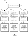
- a method 100 for producing the set of gates 10, 12, 14 will now be described, with reference to Figure 6 .
- the motor assemblies 22A, 22B, 22C of the gates 10, 12, 14 are provided. As has been described above, these motor assemblies 22A, 22B, 22C are substantially identical to each other.
- the doors 20A, 20B, 20C of the gates 10, 12, 14 are supplied.
- the door 20A of the wicket 10 is supplied equipped with tilting leaves 30 during step 120
- the door 20B of the wicket 12 is supplied equipped with side-retracting leaves 32 during step 122
- gate 14 is supplied equipped with pivoting leaves 34 during step 124.
- motor assemblies 22A, 22B, 22C are each configured according to their own operating mode during steps 130, 132, 134, respectively.
- the motor assembly 22A is assembled to the door 20A during a first assembly step 140 so as to form the first automatic gate 10
- the motor assembly 22B is assembled to the door 20B during a second assembly step 142 so as to form the second automatic gate 12
- the motor assembly 22C is assembled to the door 20C during a third assembly step 144 so as to form the third automatic gate 14.
- the motor assembly 22A is coupled directly to the leaf 30
- the motor assembly 22B is coupled directly to the connecting rod 50
- the motor assembly 22C is coupled directly to the leaf 34.
- the motor assemblies 22A, 22B, 22C are configured after having been assembled at their respective door 20A, 20B, 20C, that is to say that the steps 130, 132, 134 take place after the steps 140, 142, 144.
- each gate 10, 12, 14 is simplified since, rather than having to design for each gate 10, 12, 14 a transmission mechanism specific to said gate 10, 12, 14, it suffices to modify the setting of the motor assembly 22A, 22B, 22C so as to adapt the speed of rotation and the output torque of the motor assembly 22A, 22B, 22C to the needs. This also allows a reduction in production costs.
- the set of gates according to the invention does not necessarily include a single first gate 10, a single second gate 12 and only a third gate 14, as has been described above, but may include a plurality of each of the gates 10, 12, 14.
Landscapes
- Engineering & Computer Science (AREA)
- Civil Engineering (AREA)
- Structural Engineering (AREA)
- Physics & Mathematics (AREA)
- General Physics & Mathematics (AREA)
- Power-Operated Mechanisms For Wings (AREA)
- Devices For Checking Fares Or Tickets At Control Points (AREA)
- Moulds For Moulding Plastics Or The Like (AREA)
Priority Applications (1)
| Application Number | Priority Date | Filing Date | Title |
|---|---|---|---|
| PL18748918T PL3662454T3 (pl) | 2017-08-01 | 2018-08-01 | Zespół furtek automatycznych zawierający zasadniczo identyczne zespoły silnikowe i sposób produkcji takiego zespołu |
Applications Claiming Priority (2)
| Application Number | Priority Date | Filing Date | Title |
|---|---|---|---|
| FR1700810A FR3069867B1 (fr) | 2017-08-01 | 2017-08-01 | Ensemble de portillons automatiques comprenant des ensembles moteurs sensiblement identiques et procede de production d'un tel ensemble |
| PCT/EP2018/070847 WO2019025482A1 (fr) | 2017-08-01 | 2018-08-01 | Ensemble de portillons automatiques comprenant des ensembles moteurs sensiblement identiques et procédé de production d'un tel ensemble |
Publications (2)
| Publication Number | Publication Date |
|---|---|
| EP3662454A1 EP3662454A1 (fr) | 2020-06-10 |
| EP3662454B1 true EP3662454B1 (fr) | 2021-05-26 |
Family
ID=60302152
Family Applications (1)
| Application Number | Title | Priority Date | Filing Date |
|---|---|---|---|
| EP18748918.2A Active EP3662454B1 (fr) | 2017-08-01 | 2018-08-01 | Ensemble de portillons automatiques comprenant des ensembles moteurs sensiblement identiques et procédé de production d'un tel ensemble |
Country Status (7)
| Country | Link |
|---|---|
| US (1) | US11840876B2 (pl) |
| EP (1) | EP3662454B1 (pl) |
| CN (1) | CN110998676B (pl) |
| DK (1) | DK3662454T3 (pl) |
| FR (1) | FR3069867B1 (pl) |
| PL (1) | PL3662454T3 (pl) |
| WO (1) | WO2019025482A1 (pl) |
Families Citing this family (5)
| Publication number | Priority date | Publication date | Assignee | Title |
|---|---|---|---|---|
| CN114457722A (zh) * | 2020-11-09 | 2022-05-10 | 熵基科技股份有限公司 | 摆闸机芯 |
| EP4239602A1 (en) * | 2022-03-02 | 2023-09-06 | Skidata GmbH | Blocking element, access control device and system |
| CN114717990B (zh) * | 2022-04-22 | 2024-06-25 | 永旭(上海)通讯科技有限公司 | 一种活动闸机 |
| CN116752468B (zh) * | 2023-05-09 | 2025-11-14 | 山东锐达物联科技有限公司 | 一种具有闸板鞘的闸机 |
| US20250389144A1 (en) * | 2023-07-24 | 2025-12-25 | Bruce SCHMUTTER | System and method for weapons detection while maintaining originally-intended egress capacity |
Citations (11)
| Publication number | Priority date | Publication date | Assignee | Title |
|---|---|---|---|---|
| GB2305204A (en) | 1995-09-15 | 1997-04-02 | Dassault Automatismes | Installation for controlling access |
| DE19613178A1 (de) | 1996-04-02 | 1997-10-09 | Heinrich Landert | Verfahren zum Betrieb einer Türanlage und eine nach dem Verfahren arbeitende Türanlage |
| US6184641B1 (en) | 1998-04-21 | 2001-02-06 | The Chamberlain Group, Inc. | Controller for a door operator |
| DE10353366B3 (de) | 2003-11-14 | 2004-11-18 | Magnetic Autocontrol Gmbh | Antriebsvorrichtung für Durchgangs- oder Durchfahrtssperren und Tür- oder Torantriebe |
| DE102004048403A1 (de) | 2004-10-01 | 2006-04-06 | Kaba Gallenschütz GmbH | Zugangskontrollvorrichtung |
| DE102008016516B3 (de) | 2008-01-24 | 2009-05-20 | Kaba Gallenschütz GmbH | Zugangskontrollvorrichtung |
| DE202009010858U1 (de) | 2009-08-11 | 2009-10-22 | Magnetic Autocontrol Gmbh | Durchgangs- oder Durchfahrtssperranlage mit einer Vorrichtung zur Überwachung des Durchgangs- oder Durchfahrtsbereichs |
| DE102008025757A1 (de) | 2008-04-28 | 2009-10-29 | Kaba Gallenschütz GmbH | Türantrieb |
| CN201406648Y (zh) | 2009-04-24 | 2010-02-17 | 黄国胜 | 翼闸机或摆闸机或臂闸机或道闸机的传动机构 |
| WO2010078856A1 (de) | 2009-01-07 | 2010-07-15 | Magnetic Autocontrol Gmbh | Vorrichtung zur personendurchgangskontrolle |
| US8405337B2 (en) | 2008-11-12 | 2013-03-26 | Globe Motors, Inc. | Method of controlling an automatic door system |
Family Cites Families (43)
| Publication number | Priority date | Publication date | Assignee | Title |
|---|---|---|---|---|
| US732982A (en) * | 1903-04-06 | 1903-07-07 | Julius Wendler | Apparatus for closing entrances. |
| US1406788A (en) * | 1921-03-12 | 1922-02-14 | Weinmann Frederick | Apparatus for trapping bank robbers |
| SE305304B (pl) * | 1964-06-15 | 1968-10-21 | Barracuda Center Ab | |
| US3478467A (en) * | 1967-05-03 | 1969-11-18 | Ibm | Fare operated gate assembly |
| GB1263542A (en) * | 1968-06-14 | 1972-02-09 | Omron Tateisi Electronics Co | An automatic ticket gate |
| GB1264468A (pl) * | 1968-10-23 | 1972-02-23 | ||
| FR2273930A1 (fr) * | 1974-06-06 | 1976-01-02 | Lagarrigue Serge | Dispositif de protection installe dans la zone exterieure d'un local |
| GB2041053B (en) * | 1979-01-31 | 1983-01-12 | Pretini Gisberto | Protective door systems |
| US4586441A (en) * | 1982-06-08 | 1986-05-06 | Related Energy & Security Systems, Inc. | Security system for selectively allowing passage from a non-secure region to a secure region |
| US5195448A (en) * | 1991-12-02 | 1993-03-23 | Sims Allen G | Security system |
| US5311166A (en) * | 1992-08-18 | 1994-05-10 | Frye Filmore O | Security vestibule |
| NL9201723A (nl) * | 1992-10-06 | 1994-05-02 | Boon Edam Bv | Draaideursluis. |
| DE69401516T2 (de) * | 1993-08-27 | 1997-07-03 | Boon Edam Bv | Eingangsvorrichtung |
| US6308644B1 (en) * | 1994-06-08 | 2001-10-30 | William Diaz | Fail-safe access control chamber security system |
| US5694867A (en) * | 1994-06-08 | 1997-12-09 | Diaz-Lopez; William | Fail-safe access control chamber security system |
| FR2742185B1 (fr) * | 1995-12-08 | 1999-05-14 | D Fi | Dispositif d'entree a ouverture automatique pour zone controlee |
| ES2114501B1 (es) * | 1996-07-25 | 1999-02-01 | Dassault Automatismes | Instalacion de control de acceso por torniquete, seguido de una puerta. |
| US20020050098A1 (en) * | 2000-10-28 | 2002-05-02 | Chan Kwon Kyong | Rotary access locking apparatus |
| FR2849519B1 (fr) * | 2002-12-31 | 2005-03-11 | Automatic Systems | Porte automatisee pour permettre ou interdire l'acces a un espace ou un vehicule de transport, en particulier a une salle d'embarquement ou a un avion |
| FR2872537B1 (fr) * | 2004-07-05 | 2006-09-29 | Avidsen Soc Par Actions Simpli | Dispositif de commande automatisee d'ouverture et de fermeture de portail ou fenetre a double battant |
| DE202005015373U1 (de) * | 2005-09-29 | 2005-12-15 | Magnetic Autocontrol Gmbh | Sperrelement, insbesondere für eine Durchgangssperre |
| US8638904B2 (en) * | 2010-03-14 | 2014-01-28 | Rapiscan Systems, Inc. | Personnel screening system |
| US11326387B2 (en) * | 2008-07-18 | 2022-05-10 | Robert Osann, Jr. | Automatic access control devices and clusters thereof |
| TWM366590U (en) * | 2009-03-03 | 2009-10-11 | xin-da Chen | Auxiliary device for entrance gate |
| NL2002818C2 (en) * | 2009-04-29 | 2010-11-01 | Royal Boon Edam Group Holding B V | Revolving door lock. |
| CN201406651Y (zh) * | 2009-05-08 | 2010-02-17 | 殷新荣 | 通道翼闸机芯装置 |
| CN101871292A (zh) * | 2010-03-23 | 2010-10-27 | 张建新 | 安全通道的翼门伸缩控制方法 |
| US8766764B2 (en) * | 2010-09-23 | 2014-07-01 | Rapiscan Systems, Inc. | Automated personnel screening system and method |
| CN102108686B (zh) * | 2010-12-17 | 2012-05-02 | 上海华铭智能终端设备股份有限公司 | 可调节扇门阻拦宽度的剪式门阻拦装置 |
| CN202108358U (zh) * | 2011-04-21 | 2012-01-11 | 张建新 | 一种安全通道摆动式门翼 |
| CN203307749U (zh) * | 2012-06-29 | 2013-11-27 | 车玉萍 | 一种高效安全低噪音的翼闸机装置 |
| CN203007868U (zh) * | 2012-12-10 | 2013-06-19 | 深圳市威捷机电技术有限公司 | 平移门连动平行摆动机构 |
| FR3015746B1 (fr) * | 2013-12-20 | 2016-02-05 | Thales Sa | Systeme de controle d'acces |
| AU2015227069B2 (en) * | 2014-03-07 | 2020-05-14 | Rapiscan Systems, Inc. | Ultra wide band detectors |
| CN105155964B (zh) * | 2015-08-06 | 2017-03-29 | 北京中软万维网络技术有限公司 | 一种闸机通道拍打门装置和控制方法 |
| US9922515B2 (en) * | 2015-10-02 | 2018-03-20 | Marian Alice Hoy | Security, monitoring and safety system with containment and method of use |
| CN205591150U (zh) * | 2016-04-21 | 2016-09-21 | 苏金月 | 一种停车场道闸 |
| CN206329209U (zh) * | 2016-10-31 | 2017-07-14 | 曾文德 | 一种平移闸门机构 |
| CN206233142U (zh) * | 2016-11-25 | 2017-06-09 | 深圳科装智能电子技术有限公司 | 平移闸机芯 |
| CN206290169U (zh) * | 2016-12-27 | 2017-06-30 | 梦天木门集团有限公司 | 木镶板抗冲击实木复合门 |
| US10378268B2 (en) * | 2018-01-09 | 2019-08-13 | Jose Portilla | Building security assembly |
| US11053729B2 (en) * | 2018-06-29 | 2021-07-06 | Overhead Door Corporation | Door system and method with early warning sensors |
| US11047099B2 (en) * | 2018-09-14 | 2021-06-29 | Koei Industry Co., Ltd. | Pass blocking apparatus |
-
2017
- 2017-08-01 FR FR1700810A patent/FR3069867B1/fr active Active
-
2018
- 2018-08-01 PL PL18748918T patent/PL3662454T3/pl unknown
- 2018-08-01 DK DK18748918.2T patent/DK3662454T3/da active
- 2018-08-01 EP EP18748918.2A patent/EP3662454B1/fr active Active
- 2018-08-01 US US16/634,535 patent/US11840876B2/en active Active
- 2018-08-01 WO PCT/EP2018/070847 patent/WO2019025482A1/fr not_active Ceased
- 2018-08-01 CN CN201880054449.2A patent/CN110998676B/zh active Active
Patent Citations (11)
| Publication number | Priority date | Publication date | Assignee | Title |
|---|---|---|---|---|
| GB2305204A (en) | 1995-09-15 | 1997-04-02 | Dassault Automatismes | Installation for controlling access |
| DE19613178A1 (de) | 1996-04-02 | 1997-10-09 | Heinrich Landert | Verfahren zum Betrieb einer Türanlage und eine nach dem Verfahren arbeitende Türanlage |
| US6184641B1 (en) | 1998-04-21 | 2001-02-06 | The Chamberlain Group, Inc. | Controller for a door operator |
| DE10353366B3 (de) | 2003-11-14 | 2004-11-18 | Magnetic Autocontrol Gmbh | Antriebsvorrichtung für Durchgangs- oder Durchfahrtssperren und Tür- oder Torantriebe |
| DE102004048403A1 (de) | 2004-10-01 | 2006-04-06 | Kaba Gallenschütz GmbH | Zugangskontrollvorrichtung |
| DE102008016516B3 (de) | 2008-01-24 | 2009-05-20 | Kaba Gallenschütz GmbH | Zugangskontrollvorrichtung |
| DE102008025757A1 (de) | 2008-04-28 | 2009-10-29 | Kaba Gallenschütz GmbH | Türantrieb |
| US8405337B2 (en) | 2008-11-12 | 2013-03-26 | Globe Motors, Inc. | Method of controlling an automatic door system |
| WO2010078856A1 (de) | 2009-01-07 | 2010-07-15 | Magnetic Autocontrol Gmbh | Vorrichtung zur personendurchgangskontrolle |
| CN201406648Y (zh) | 2009-04-24 | 2010-02-17 | 黄国胜 | 翼闸机或摆闸机或臂闸机或道闸机的传动机构 |
| DE202009010858U1 (de) | 2009-08-11 | 2009-10-22 | Magnetic Autocontrol Gmbh | Durchgangs- oder Durchfahrtssperranlage mit einer Vorrichtung zur Überwachung des Durchgangs- oder Durchfahrtsbereichs |
Non-Patent Citations (9)
| Title |
|---|
| ANONYMOUS: "FOTOGRAFIE EINER ÖFFENTLICH ZUGÄNGLICHEN ANLAGE ZUR PERSONENZUGANGS- KONTROLLE IN SAO PAULO, BRASILIEN", GALERIA DA ARGUITETURA, 18 February 2022 (2022-02-18), pages 1 - 3, XP055905228, Retrieved from the Internet <URL:https://www.galeriadaarguitetura.com.br/projeto/dal-pian-arquitetos/nasp-sede-administrativa-natura-sao-paulo/2834> |
| ANONYMOUS: "Info KPR Kit Set", PROSPEKT MAGENTIC AUTOCONTROL, July 2006 (2006-07-01), pages 1 - 4, XP055905208 |
| ANONYMOUS: "Parameter (Informatik)", WIKIPEDIA (ACCESSED VIA THE WAYBACK MACHINE), XP093256179, Retrieved from the Internet <URL:https://web.archive.org/web/20170319002438/https://de.wikipedia.org/wiki/Parameter_(Informatik)#expand> |
| ANONYMOUS: "Pedestrian Gates MPH 112", PROSPEKT MAGNETIC AUTOCONTROL:, November 2014 (2014-11-01), pages 1 - 2, XP055904944 |
| ANONYMOUS: "Pedestrian Gates MPS 122", PROSPEKT MAGENTIC AUTOCONTROL, November 2014 (2014-11-01), pages 1 - 2, XP055904944 |
| ANONYMOUS: "Pedestrian Gates MRP 112", PROSPEKT MAGNETIC AUTOCONTROL, November 2014 (2014-11-01), pages 1 - 2, XP055904936 |
| ANONYMOUS: "Was ist der Unterschied zwischen Parametrierung, Konguration und Programmierung?", GUTEFRAGE.NET, XP093256174, Retrieved from the Internet <URL:https://www.gutefrage.net/frage/was-ist-der-unterschied-zwischen-parametrierung-konfiguration-und-programmierung#google_vignette> |
| ANONYMOUS: "X-Bar Automatic barrier ", NICE SPA, vol. 94, no. 3, pages 506 - 511, XP093256181, Retrieved from the Internet <URL:https://www.niceforyou.com/sites/default/files/upload/manuals/ISTXBARR01.4851.pdf> DOI: 10.1002/cjce.22400 |
| D19 - INSTALLATIONS-UND GEBRAUCHSANLEITUNG „DEIMOS ULTRA BT A 400/600 (no date to be found) |
Also Published As
| Publication number | Publication date |
|---|---|
| PL3662454T3 (pl) | 2021-11-22 |
| EP3662454A1 (fr) | 2020-06-10 |
| CN110998676A (zh) | 2020-04-10 |
| CN110998676B (zh) | 2022-04-01 |
| FR3069867A1 (fr) | 2019-02-08 |
| DK3662454T3 (da) | 2021-07-05 |
| US20200181977A1 (en) | 2020-06-11 |
| WO2019025482A1 (fr) | 2019-02-07 |
| US11840876B2 (en) | 2023-12-12 |
| FR3069867B1 (fr) | 2021-04-09 |
Similar Documents
| Publication | Publication Date | Title |
|---|---|---|
| EP3662454B1 (fr) | Ensemble de portillons automatiques comprenant des ensembles moteurs sensiblement identiques et procédé de production d'un tel ensemble | |
| FR2899886A1 (fr) | Ensemble actionneur de portes a galets entraines par moteur. | |
| CN108688452B (zh) | 举升式车门总成 | |
| CN1534159A (zh) | 可活动家具部件在其关闭区域的运动阻尼装置 | |
| GB2329931A (en) | Aircraft door : compound movement : drive : lock | |
| CA2768180A1 (fr) | Systeme d'ouvrant pour un engin a moteur, en particulier pour un vehicule automobile | |
| EP1247675A1 (en) | Wing opening and closing device for truck | |
| WO2022223649A1 (fr) | Dispositif d'obturation d'entree d'air de face avant de vehicule automobile | |
| EP2622157B1 (fr) | Poignée d'ouvrant de véhicule comprenant deux leviers | |
| WO1997021898A1 (fr) | Dispositif d'entree a ouverture automatique pour zone controlee | |
| US6053451A (en) | Remote-control flight vehicle structure | |
| CN118375360A (zh) | 用于车辆的车门铰接装置 | |
| EP2829470A1 (fr) | Dispositif d'entraînement en rotation d'une roue d'aéronef | |
| US6513285B2 (en) | Device for opening and closing a vehicle slide door window | |
| EP0484258A1 (fr) | Dispositif de commande d'ouverture et de fermeture d'un vantail pivotant sur 180 degrés et installation incluant un tel dispositif | |
| FR3056959A1 (fr) | Mecanisme pour un element de carrosserie de vehicule | |
| US5724198A (en) | Retractable rear under view mirror device for an automotive vehicle | |
| WO2017042391A1 (fr) | Système d'ouverture de hayon présentant plusieurs cinématiques d'ouverture | |
| EP3874112B1 (fr) | Coffre latéral à vantail basculant pour portillon de contrôle d'accès à une zone réservée | |
| HK40027215A (en) | Assembly of automatic gates comprising substantially identical motor assemblies and method for producing such an assembly | |
| HK40027215B (en) | Assembly of automatic gates comprising substantially identical motor assemblies and method for producing such an assembly | |
| CN212716270U (zh) | 后背门铰链机构及汽车 | |
| WO2023104816A1 (fr) | Dispositif d'obstruction de passage et portillon d'accès associé | |
| FR2983510A1 (fr) | Systeme de charniere pour le reglage de la position d'un volet sur la caisse d'un vehicule. | |
| KR20020093233A (ko) | 자동차의 도어 힌지 조립체 |
Legal Events
| Date | Code | Title | Description |
|---|---|---|---|
| STAA | Information on the status of an ep patent application or granted ep patent |
Free format text: STATUS: UNKNOWN |
|
| STAA | Information on the status of an ep patent application or granted ep patent |
Free format text: STATUS: THE INTERNATIONAL PUBLICATION HAS BEEN MADE |
|
| PUAI | Public reference made under article 153(3) epc to a published international application that has entered the european phase |
Free format text: ORIGINAL CODE: 0009012 |
|
| STAA | Information on the status of an ep patent application or granted ep patent |
Free format text: STATUS: REQUEST FOR EXAMINATION WAS MADE |
|
| 17P | Request for examination filed |
Effective date: 20200130 |
|
| AK | Designated contracting states |
Kind code of ref document: A1 Designated state(s): AL AT BE BG CH CY CZ DE DK EE ES FI FR GB GR HR HU IE IS IT LI LT LU LV MC MK MT NL NO PL PT RO RS SE SI SK SM TR |
|
| AX | Request for extension of the european patent |
Extension state: BA ME |
|
| DAV | Request for validation of the european patent (deleted) | ||
| DAX | Request for extension of the european patent (deleted) | ||
| REG | Reference to a national code |
Ref country code: HK Ref legal event code: DE Ref document number: 40027215 Country of ref document: HK |
|
| GRAP | Despatch of communication of intention to grant a patent |
Free format text: ORIGINAL CODE: EPIDOSNIGR1 |
|
| STAA | Information on the status of an ep patent application or granted ep patent |
Free format text: STATUS: GRANT OF PATENT IS INTENDED |
|
| INTG | Intention to grant announced |
Effective date: 20210119 |
|
| GRAS | Grant fee paid |
Free format text: ORIGINAL CODE: EPIDOSNIGR3 |
|
| GRAA | (expected) grant |
Free format text: ORIGINAL CODE: 0009210 |
|
| STAA | Information on the status of an ep patent application or granted ep patent |
Free format text: STATUS: THE PATENT HAS BEEN GRANTED |
|
| AK | Designated contracting states |
Kind code of ref document: B1 Designated state(s): AL AT BE BG CH CY CZ DE DK EE ES FI FR GB GR HR HU IE IS IT LI LT LU LV MC MK MT NL NO PL PT RO RS SE SI SK SM TR |
|
| REG | Reference to a national code |
Ref country code: GB Ref legal event code: FG4D Free format text: NOT ENGLISH |
|
| REG | Reference to a national code |
Ref country code: CH Ref legal event code: EP |
|
| REG | Reference to a national code |
Ref country code: AT Ref legal event code: REF Ref document number: 1396991 Country of ref document: AT Kind code of ref document: T Effective date: 20210615 |
|
| REG | Reference to a national code |
Ref country code: DE Ref legal event code: R096 Ref document number: 602018017758 Country of ref document: DE |
|
| REG | Reference to a national code |
Ref country code: IE Ref legal event code: FG4D Free format text: LANGUAGE OF EP DOCUMENT: FRENCH |
|
| REG | Reference to a national code |
Ref country code: DK Ref legal event code: T3 Effective date: 20210630 |
|
| REG | Reference to a national code |
Ref country code: SE Ref legal event code: TRGR |
|
| REG | Reference to a national code |
Ref country code: NL Ref legal event code: FP |
|
| REG | Reference to a national code |
Ref country code: LT Ref legal event code: MG9D |
|
| REG | Reference to a national code |
Ref country code: AT Ref legal event code: MK05 Ref document number: 1396991 Country of ref document: AT Kind code of ref document: T Effective date: 20210526 |
|
| PG25 | Lapsed in a contracting state [announced via postgrant information from national office to epo] |
Ref country code: FI Free format text: LAPSE BECAUSE OF FAILURE TO SUBMIT A TRANSLATION OF THE DESCRIPTION OR TO PAY THE FEE WITHIN THE PRESCRIBED TIME-LIMIT Effective date: 20210526 Ref country code: HR Free format text: LAPSE BECAUSE OF FAILURE TO SUBMIT A TRANSLATION OF THE DESCRIPTION OR TO PAY THE FEE WITHIN THE PRESCRIBED TIME-LIMIT Effective date: 20210526 Ref country code: LT Free format text: LAPSE BECAUSE OF FAILURE TO SUBMIT A TRANSLATION OF THE DESCRIPTION OR TO PAY THE FEE WITHIN THE PRESCRIBED TIME-LIMIT Effective date: 20210526 Ref country code: BG Free format text: LAPSE BECAUSE OF FAILURE TO SUBMIT A TRANSLATION OF THE DESCRIPTION OR TO PAY THE FEE WITHIN THE PRESCRIBED TIME-LIMIT Effective date: 20210826 Ref country code: AT Free format text: LAPSE BECAUSE OF FAILURE TO SUBMIT A TRANSLATION OF THE DESCRIPTION OR TO PAY THE FEE WITHIN THE PRESCRIBED TIME-LIMIT Effective date: 20210526 |
|
| PG25 | Lapsed in a contracting state [announced via postgrant information from national office to epo] |
Ref country code: NO Free format text: LAPSE BECAUSE OF FAILURE TO SUBMIT A TRANSLATION OF THE DESCRIPTION OR TO PAY THE FEE WITHIN THE PRESCRIBED TIME-LIMIT Effective date: 20210826 Ref country code: LV Free format text: LAPSE BECAUSE OF FAILURE TO SUBMIT A TRANSLATION OF THE DESCRIPTION OR TO PAY THE FEE WITHIN THE PRESCRIBED TIME-LIMIT Effective date: 20210526 Ref country code: RS Free format text: LAPSE BECAUSE OF FAILURE TO SUBMIT A TRANSLATION OF THE DESCRIPTION OR TO PAY THE FEE WITHIN THE PRESCRIBED TIME-LIMIT Effective date: 20210526 Ref country code: PT Free format text: LAPSE BECAUSE OF FAILURE TO SUBMIT A TRANSLATION OF THE DESCRIPTION OR TO PAY THE FEE WITHIN THE PRESCRIBED TIME-LIMIT Effective date: 20210927 Ref country code: IS Free format text: LAPSE BECAUSE OF FAILURE TO SUBMIT A TRANSLATION OF THE DESCRIPTION OR TO PAY THE FEE WITHIN THE PRESCRIBED TIME-LIMIT Effective date: 20210926 Ref country code: GR Free format text: LAPSE BECAUSE OF FAILURE TO SUBMIT A TRANSLATION OF THE DESCRIPTION OR TO PAY THE FEE WITHIN THE PRESCRIBED TIME-LIMIT Effective date: 20210827 |
|
| PG25 | Lapsed in a contracting state [announced via postgrant information from national office to epo] |
Ref country code: CZ Free format text: LAPSE BECAUSE OF FAILURE TO SUBMIT A TRANSLATION OF THE DESCRIPTION OR TO PAY THE FEE WITHIN THE PRESCRIBED TIME-LIMIT Effective date: 20210526 Ref country code: SM Free format text: LAPSE BECAUSE OF FAILURE TO SUBMIT A TRANSLATION OF THE DESCRIPTION OR TO PAY THE FEE WITHIN THE PRESCRIBED TIME-LIMIT Effective date: 20210526 Ref country code: RO Free format text: LAPSE BECAUSE OF FAILURE TO SUBMIT A TRANSLATION OF THE DESCRIPTION OR TO PAY THE FEE WITHIN THE PRESCRIBED TIME-LIMIT Effective date: 20210526 Ref country code: EE Free format text: LAPSE BECAUSE OF FAILURE TO SUBMIT A TRANSLATION OF THE DESCRIPTION OR TO PAY THE FEE WITHIN THE PRESCRIBED TIME-LIMIT Effective date: 20210526 Ref country code: ES Free format text: LAPSE BECAUSE OF FAILURE TO SUBMIT A TRANSLATION OF THE DESCRIPTION OR TO PAY THE FEE WITHIN THE PRESCRIBED TIME-LIMIT Effective date: 20210526 Ref country code: SK Free format text: LAPSE BECAUSE OF FAILURE TO SUBMIT A TRANSLATION OF THE DESCRIPTION OR TO PAY THE FEE WITHIN THE PRESCRIBED TIME-LIMIT Effective date: 20210526 |
|
| REG | Reference to a national code |
Ref country code: DE Ref legal event code: R026 Ref document number: 602018017758 Country of ref document: DE |
|
| PLBI | Opposition filed |
Free format text: ORIGINAL CODE: 0009260 |
|
| PLAX | Notice of opposition and request to file observation + time limit sent |
Free format text: ORIGINAL CODE: EPIDOSNOBS2 |
|
| REG | Reference to a national code |
Ref country code: CH Ref legal event code: PL |
|
| PG25 | Lapsed in a contracting state [announced via postgrant information from national office to epo] |
Ref country code: MC Free format text: LAPSE BECAUSE OF FAILURE TO SUBMIT A TRANSLATION OF THE DESCRIPTION OR TO PAY THE FEE WITHIN THE PRESCRIBED TIME-LIMIT Effective date: 20210526 |
|
| 26 | Opposition filed |
Opponent name: MAGNETIC AUTOCONTROL GMBH Effective date: 20220228 |
|
| REG | Reference to a national code |
Ref country code: BE Ref legal event code: MM Effective date: 20210831 |
|
| PG25 | Lapsed in a contracting state [announced via postgrant information from national office to epo] |
Ref country code: LI Free format text: LAPSE BECAUSE OF NON-PAYMENT OF DUE FEES Effective date: 20210831 Ref country code: CH Free format text: LAPSE BECAUSE OF NON-PAYMENT OF DUE FEES Effective date: 20210831 |
|
| PG25 | Lapsed in a contracting state [announced via postgrant information from national office to epo] |
Ref country code: IS Free format text: LAPSE BECAUSE OF FAILURE TO SUBMIT A TRANSLATION OF THE DESCRIPTION OR TO PAY THE FEE WITHIN THE PRESCRIBED TIME-LIMIT Effective date: 20210926 Ref country code: LU Free format text: LAPSE BECAUSE OF NON-PAYMENT OF DUE FEES Effective date: 20210801 Ref country code: AL Free format text: LAPSE BECAUSE OF FAILURE TO SUBMIT A TRANSLATION OF THE DESCRIPTION OR TO PAY THE FEE WITHIN THE PRESCRIBED TIME-LIMIT Effective date: 20210526 |
|
| PLBB | Reply of patent proprietor to notice(s) of opposition received |
Free format text: ORIGINAL CODE: EPIDOSNOBS3 |
|
| PG25 | Lapsed in a contracting state [announced via postgrant information from national office to epo] |
Ref country code: IE Free format text: LAPSE BECAUSE OF NON-PAYMENT OF DUE FEES Effective date: 20210801 Ref country code: BE Free format text: LAPSE BECAUSE OF NON-PAYMENT OF DUE FEES Effective date: 20210831 |
|
| GBPC | Gb: european patent ceased through non-payment of renewal fee |
Effective date: 20220801 |
|
| P01 | Opt-out of the competence of the unified patent court (upc) registered |
Effective date: 20230425 |
|
| PG25 | Lapsed in a contracting state [announced via postgrant information from national office to epo] |
Ref country code: CY Free format text: LAPSE BECAUSE OF FAILURE TO SUBMIT A TRANSLATION OF THE DESCRIPTION OR TO PAY THE FEE WITHIN THE PRESCRIBED TIME-LIMIT Effective date: 20210526 |
|
| PG25 | Lapsed in a contracting state [announced via postgrant information from national office to epo] |
Ref country code: HU Free format text: LAPSE BECAUSE OF FAILURE TO SUBMIT A TRANSLATION OF THE DESCRIPTION OR TO PAY THE FEE WITHIN THE PRESCRIBED TIME-LIMIT; INVALID AB INITIO Effective date: 20180801 |
|
| PG25 | Lapsed in a contracting state [announced via postgrant information from national office to epo] |
Ref country code: GB Free format text: LAPSE BECAUSE OF NON-PAYMENT OF DUE FEES Effective date: 20220801 |
|
| PG25 | Lapsed in a contracting state [announced via postgrant information from national office to epo] |
Ref country code: MK Free format text: LAPSE BECAUSE OF FAILURE TO SUBMIT A TRANSLATION OF THE DESCRIPTION OR TO PAY THE FEE WITHIN THE PRESCRIBED TIME-LIMIT Effective date: 20210526 |
|
| PG25 | Lapsed in a contracting state [announced via postgrant information from national office to epo] |
Ref country code: TR Free format text: LAPSE BECAUSE OF FAILURE TO SUBMIT A TRANSLATION OF THE DESCRIPTION OR TO PAY THE FEE WITHIN THE PRESCRIBED TIME-LIMIT Effective date: 20210526 |
|
| PG25 | Lapsed in a contracting state [announced via postgrant information from national office to epo] |
Ref country code: MT Free format text: LAPSE BECAUSE OF FAILURE TO SUBMIT A TRANSLATION OF THE DESCRIPTION OR TO PAY THE FEE WITHIN THE PRESCRIBED TIME-LIMIT Effective date: 20210526 |
|
| PGFP | Annual fee paid to national office [announced via postgrant information from national office to epo] |
Ref country code: NL Payment date: 20250724 Year of fee payment: 8 |
|
| PGFP | Annual fee paid to national office [announced via postgrant information from national office to epo] |
Ref country code: DE Payment date: 20250812 Year of fee payment: 8 Ref country code: DK Payment date: 20250729 Year of fee payment: 8 |
|
| PGFP | Annual fee paid to national office [announced via postgrant information from national office to epo] |
Ref country code: PL Payment date: 20250722 Year of fee payment: 8 Ref country code: IT Payment date: 20250808 Year of fee payment: 8 |
|
| PGFP | Annual fee paid to national office [announced via postgrant information from national office to epo] |
Ref country code: FR Payment date: 20250828 Year of fee payment: 8 |
|
| PGFP | Annual fee paid to national office [announced via postgrant information from national office to epo] |
Ref country code: SE Payment date: 20250826 Year of fee payment: 8 |
|
| PUAH | Patent maintained in amended form |
Free format text: ORIGINAL CODE: 0009272 |
|
| STAA | Information on the status of an ep patent application or granted ep patent |
Free format text: STATUS: PATENT MAINTAINED AS AMENDED |
|
| REG | Reference to a national code |
Ref country code: CH Ref legal event code: M12 Free format text: ST27 STATUS EVENT CODE: U-0-0-M10-M12 (AS PROVIDED BY THE NATIONAL OFFICE) Effective date: 20260204 |