EP3662278B1 - System, verfahren und computerprogrammprodukt zur gasanalyse - Google Patents
System, verfahren und computerprogrammprodukt zur gasanalyse Download PDFInfo
- Publication number
- EP3662278B1 EP3662278B1 EP19748382.9A EP19748382A EP3662278B1 EP 3662278 B1 EP3662278 B1 EP 3662278B1 EP 19748382 A EP19748382 A EP 19748382A EP 3662278 B1 EP3662278 B1 EP 3662278B1
- Authority
- EP
- European Patent Office
- Prior art keywords
- gas
- average
- target
- attenuation
- sensor
- Prior art date
- Legal status (The legal status is an assumption and is not a legal conclusion. Google has not performed a legal analysis and makes no representation as to the accuracy of the status listed.)
- Active
Links
Images


Classifications
-
- G—PHYSICS
- G01—MEASURING; TESTING
- G01N—INVESTIGATING OR ANALYSING MATERIALS BY DETERMINING THEIR CHEMICAL OR PHYSICAL PROPERTIES
- G01N29/00—Investigating or analysing materials by the use of ultrasonic, sonic or infrasonic waves; Visualisation of the interior of objects by transmitting ultrasonic or sonic waves through the object
- G01N29/22—Details, e.g. general constructional or apparatus details
- G01N29/24—Probes
- G01N29/2462—Probes with waveguides, e.g. SAW devices
-
- G—PHYSICS
- G01—MEASURING; TESTING
- G01N—INVESTIGATING OR ANALYSING MATERIALS BY DETERMINING THEIR CHEMICAL OR PHYSICAL PROPERTIES
- G01N29/00—Investigating or analysing materials by the use of ultrasonic, sonic or infrasonic waves; Visualisation of the interior of objects by transmitting ultrasonic or sonic waves through the object
- G01N29/02—Analysing fluids
- G01N29/022—Fluid sensors based on microsensors, e.g. quartz crystal-microbalance [QCM], surface acoustic wave [SAW] devices, tuning forks, cantilevers, flexural plate wave [FPW] devices
-
- G—PHYSICS
- G01—MEASURING; TESTING
- G01N—INVESTIGATING OR ANALYSING MATERIALS BY DETERMINING THEIR CHEMICAL OR PHYSICAL PROPERTIES
- G01N29/00—Investigating or analysing materials by the use of ultrasonic, sonic or infrasonic waves; Visualisation of the interior of objects by transmitting ultrasonic or sonic waves through the object
- G01N29/02—Analysing fluids
- G01N29/032—Analysing fluids by measuring attenuation of acoustic waves
-
- G—PHYSICS
- G01—MEASURING; TESTING
- G01N—INVESTIGATING OR ANALYSING MATERIALS BY DETERMINING THEIR CHEMICAL OR PHYSICAL PROPERTIES
- G01N29/00—Investigating or analysing materials by the use of ultrasonic, sonic or infrasonic waves; Visualisation of the interior of objects by transmitting ultrasonic or sonic waves through the object
- G01N29/22—Details, e.g. general constructional or apparatus details
- G01N29/221—Arrangements for directing or focusing the acoustical waves
-
- G—PHYSICS
- G01—MEASURING; TESTING
- G01N—INVESTIGATING OR ANALYSING MATERIALS BY DETERMINING THEIR CHEMICAL OR PHYSICAL PROPERTIES
- G01N29/00—Investigating or analysing materials by the use of ultrasonic, sonic or infrasonic waves; Visualisation of the interior of objects by transmitting ultrasonic or sonic waves through the object
- G01N29/22—Details, e.g. general constructional or apparatus details
- G01N29/222—Constructional or flow details for analysing fluids
-
- G—PHYSICS
- G01—MEASURING; TESTING
- G01N—INVESTIGATING OR ANALYSING MATERIALS BY DETERMINING THEIR CHEMICAL OR PHYSICAL PROPERTIES
- G01N29/00—Investigating or analysing materials by the use of ultrasonic, sonic or infrasonic waves; Visualisation of the interior of objects by transmitting ultrasonic or sonic waves through the object
- G01N29/34—Generating the ultrasonic, sonic or infrasonic waves, e.g. electronic circuits specially adapted therefor
- G01N29/348—Generating the ultrasonic, sonic or infrasonic waves, e.g. electronic circuits specially adapted therefor with frequency characteristics, e.g. single frequency signals, chirp signals
-
- G—PHYSICS
- G01—MEASURING; TESTING
- G01N—INVESTIGATING OR ANALYSING MATERIALS BY DETERMINING THEIR CHEMICAL OR PHYSICAL PROPERTIES
- G01N29/00—Investigating or analysing materials by the use of ultrasonic, sonic or infrasonic waves; Visualisation of the interior of objects by transmitting ultrasonic or sonic waves through the object
- G01N29/44—Processing the detected response signal, e.g. electronic circuits specially adapted therefor
- G01N29/4409—Processing the detected response signal, e.g. electronic circuits specially adapted therefor by comparison
- G01N29/4436—Processing the detected response signal, e.g. electronic circuits specially adapted therefor by comparison with a reference signal
-
- G—PHYSICS
- G01—MEASURING; TESTING
- G01N—INVESTIGATING OR ANALYSING MATERIALS BY DETERMINING THEIR CHEMICAL OR PHYSICAL PROPERTIES
- G01N29/00—Investigating or analysing materials by the use of ultrasonic, sonic or infrasonic waves; Visualisation of the interior of objects by transmitting ultrasonic or sonic waves through the object
- G01N29/44—Processing the detected response signal, e.g. electronic circuits specially adapted therefor
- G01N29/4472—Mathematical theories or simulation
-
- G—PHYSICS
- G01—MEASURING; TESTING
- G01N—INVESTIGATING OR ANALYSING MATERIALS BY DETERMINING THEIR CHEMICAL OR PHYSICAL PROPERTIES
- G01N33/00—Investigating or analysing materials by specific methods not covered by groups G01N1/00 - G01N31/00
- G01N33/0004—Gaseous mixtures, e.g. polluted air
- G01N33/0009—General constructional details of gas analysers, e.g. portable test equipment
- G01N33/0027—General constructional details of gas analysers, e.g. portable test equipment concerning the detector
- G01N33/0036—General constructional details of gas analysers, e.g. portable test equipment concerning the detector specially adapted to detect a particular component
- G01N33/005—H2
-
- G—PHYSICS
- G01—MEASURING; TESTING
- G01N—INVESTIGATING OR ANALYSING MATERIALS BY DETERMINING THEIR CHEMICAL OR PHYSICAL PROPERTIES
- G01N2291/00—Indexing codes associated with group G01N29/00
- G01N2291/02—Indexing codes associated with the analysed material
- G01N2291/021—Gases
- G01N2291/0212—Binary gases
-
- G—PHYSICS
- G01—MEASURING; TESTING
- G01N—INVESTIGATING OR ANALYSING MATERIALS BY DETERMINING THEIR CHEMICAL OR PHYSICAL PROPERTIES
- G01N2291/00—Indexing codes associated with group G01N29/00
- G01N2291/02—Indexing codes associated with the analysed material
- G01N2291/021—Gases
- G01N2291/0215—Mixtures of three or more gases, e.g. air
-
- G—PHYSICS
- G01—MEASURING; TESTING
- G01N—INVESTIGATING OR ANALYSING MATERIALS BY DETERMINING THEIR CHEMICAL OR PHYSICAL PROPERTIES
- G01N2291/00—Indexing codes associated with group G01N29/00
- G01N2291/02—Indexing codes associated with the analysed material
- G01N2291/025—Change of phase or condition
- G01N2291/0255—(Bio)chemical reactions, e.g. on biosensors
-
- G—PHYSICS
- G01—MEASURING; TESTING
- G01N—INVESTIGATING OR ANALYSING MATERIALS BY DETERMINING THEIR CHEMICAL OR PHYSICAL PROPERTIES
- G01N2291/00—Indexing codes associated with group G01N29/00
- G01N2291/02—Indexing codes associated with the analysed material
- G01N2291/025—Change of phase or condition
- G01N2291/0256—Adsorption, desorption, surface mass change, e.g. on biosensors
-
- G—PHYSICS
- G01—MEASURING; TESTING
- G01N—INVESTIGATING OR ANALYSING MATERIALS BY DETERMINING THEIR CHEMICAL OR PHYSICAL PROPERTIES
- G01N2291/00—Indexing codes associated with group G01N29/00
- G01N2291/04—Wave modes and trajectories
- G01N2291/042—Wave modes
- G01N2291/0423—Surface waves, e.g. Rayleigh waves, Love waves
-
- G—PHYSICS
- G01—MEASURING; TESTING
- G01N—INVESTIGATING OR ANALYSING MATERIALS BY DETERMINING THEIR CHEMICAL OR PHYSICAL PROPERTIES
- G01N2291/00—Indexing codes associated with group G01N29/00
- G01N2291/10—Number of transducers
- G01N2291/101—Number of transducers one transducer
Definitions
- composition in background gases In oil and gas industry, trace moisture sensors in natural gas are used, but variation of composition in background gases degrades the precision of the sensors. The composition variation takes place when the gas production condition is changed. Also, the composition of background gases is an important parameter for evaluating the heat value. Thus, the composition of background gases is usually measured by gas chromatography (GC), but GC is large and expensive apparatus.
- GC gas chromatography
- NPL non patent literature 1
- a ball SAW sensor has been developed and applied to a trace moisture sensor.
- the SAW excited on a spherical surface with a specific condition may be naturally collimated, and multiple roundtrips along the equator of the ball can be realized.
- the ball sensor based on the multiple-roundtrips effect of the SAW may provide high performance, such as high sensitivity and wide sensing range.
- SAW attenuation due to propagation at the boundary between a solid and a monatomic gas is described.
- frequency dependence of SAW attenuation by a gas is described.
- a second aspect of the present invention inheres in a method for gas analysis, as defined in claim 9.
- Preferred features are defined in the dependent claims.
- a third aspect of the present invention inheres in a computer program product, as defined in claim 17.
- ⁇ , ⁇ , ⁇ , ⁇ and ⁇ represent Greek alphabet characters, respectively.
- the "horizontal” direction or the "vertical” direction is simply assigned for convenience of explanation and does not limit the technical spirit of the present invention. Therefore, for example, when the plane of paper is rotated 90 degrees, the "horizontal” direction is changed to the “vertical” direction and the “vertical” direction is changed to the “horizontal” direction. When the plane of paper is rotated 180 degrees, the "left” side is changed to the "right” side and the “right” side is changed to the “left” side. Therefore, various changes can be added to the technical ideas of the present invention, within the technical scope prescribed by claims.
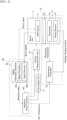
- a system for gas analysis, or a gas analyzer includes a sensor unit 1, a temperature controller 16, a gas supply unit 17, a velocity measurement unit 18 and a signal processing unit 40.
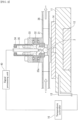
- the sensor unit 1 as illustrated in Fig. 2 , has a SAW sensor 2, which is a ball SAW sensor, embedded in a tubular sensor cell 31, wherein the tubular sensor cell 31 is fixed on a plate-shaped adapter 14 disposed on a block-shaped holder 11.
- the inner structure of the sensor cell 31 has a concave configuration for mounting a lower portion of the SAW sensor 2 in a tubular topology of the sensor cell 31.
- An electrode-holder base 32 is fixed on the sensor cell 31, such that the bottom of the electrode-holder base 32 is inserted in an inner wall of a window, which is vertically cut at the top wall of the sensor cell 31.
- a top of the electrode-holder base 32 is capped by a sensor-cell cap 33.
- the SAW sensor 2 is connected to a rod-shaped external electrode 35 through a contact pin 35a along a vertical direction via the canal at the bottom of the electrode-holder base 32.
- the external electrode 35 is held in a hollow space of a vertically aligned cylindrical electrode holder 34, the bottom of which is inserted in an inner portion of the sensor-cell cap 33.
- a sensing gas containing in a background gas for example, a humid gas, is introduced into the sensor cell 31 through a horizontally aligned tubing 36 with a gas flow rate v, so that the humid gas can touch the surface of the SAW sensor 2.
- the gas flow rate v is typically 0.1 L/min to 1 L/min.
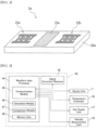
- the SAW sensor 2 may have a sensor electrode 22 and a sensitive film 23 arranged in predetermined areas on the surface of a homogeneous piezoelectric ball 20.
- the piezoelectric ball 20 provides a homogeneous material sphere, on which a circular orbital band for propagating a SAW can be defined.
- the sensor electrode 22 generates a collimated beam 21 of the SAW, which includes a fundamental wave of a first frequency and a harmonic wave of a second frequency, propagates repeatedly through the circular orbital path defined on the piezoelectric ball 20 while passing through the sensitive film 23 deposited on the orbital path.
- the sensitive film 23 can be formed on almost the entire surface of the orbital band, which defines the orbital path on the three-dimensional base body. Because the sensitive film 21 is configured to react with specific gas molecules, the sensitive film 21 adsorbs water vapor in the sensing gas-to-be-measured.
- a crystal sphere such as quartz, langasite (La 3 Ga 5 SiO 14 ), lithium niobate (LiNbO 3 ), lithium tantalate (LiTaO 3 ), piezoelectric ceramics (PZT), bismuth germanium oxide (Bi 12 GeO 20 ) and the like, may be used.
- a silica (SiO x ) film and the like may be used.
- the sensor electrode 22 may be deposited in an opening of the sensitive film 23, the opening exposes a part of the surface of the piezoelectric ball 20, in a configuration such that the opening is formed on a part of the equator of the homogeneous piezoelectric ball 20.
- an interdigital electrode (IDT) using a chromium (Cr) film and the like may be used as an electroacoustic transducer.
- IDT interdigital electrode
- Cr chromium
- a SAW orbiting route is limited to a specific orbital band having a constant width, depending on type of crystal material. The width of the orbital band may be increased or decreased depending on anisotropy of the crystal.
- the collimated beam 21 is scheduled to propagate many turns passing through the sensitive film 23, which is configured to adsorb water molecules. Because the adsorbed water molecules change the propagation characteristic of the SAW, the changes due to adsorbed water molecules in the humid gas on the sensitive film 23 can be integrated every turn through the multiple roundtrips. Thus, even though the sensitive film 23 may be so thin as to adsorb the small amount of the water vapor, measurement accuracy of gas analysis may be increased.
- the second frequency f 2 is 240 MHz for the third-order harmonic wave or 400 MHz for the fifth-order harmonic wave.
- Appropriate range of the first frequency f 1 for the piezoelectric ball 20 of 3.3 millimeters diameter may be from 60 MHz to 100 MHz, and the most suitable first frequency f 1 may be 80 MHz.
- the first frequency f1 is inversely proportional to the diameter of the piezoelectric ball 20.
- the SAW sensor 2 may be fabricated as described below.
- a pattern of an IDT of about 150 nanometers thick Cr film is deposited on a surface of a quartz ball having a diameter of 3.3 millimeters.
- the IDT has a pair of bus bars, and a plurality of electrode fingers extending from the bas bars, respectively.
- the electrode fingers overlap each other with a cross width Wc, and each electrode finger has a width Wf and a periodicity P.
- the cross width Wc, the width Wf and the periodicity P are designed as 364 micrometers, 6.51 micrometers and 10.0 micrometers, respectively, for the natural collimation of 80 MHz SAW (refer to NPL 1).
- the IDT on the quartz ball having 3.3 millimeters diameter can generate 80 MHz SAW as a fundamental wave and 240 MHz SAW as a third-order harmonic wave.
- a silica film is synthesized by using a sol-gel method and coated on the surface of the quartz ball as follows: 3.47 grams of tetraethoxysilane (TEOS), 0.75 grams of isopropanol (IPA), and 1.50 grams of 0.1N hydrochloric acid (HCl) are mixed and stirred by sonication (27, 45, 100 kHz, 60 minutes).
- TEOS is polymerized by hydrolysis and resulted in SiO x .
- the mixture is diluted with IPA and 0.5 mass% SiO x solution is obtained.
- the surface of propagation route of SAW is coated with the SiO x solution using a spin coating. Condition of the spin coating is 3000 rpm for 20 seconds.
- the thickness of SiO x film is confirmed as 1029 nanometers from measurement using interference microscope.
- An RF voltage is applied to the sensor electrode 22 via an electrode pad (not illustrated) arranged around the north-pole, which is a top of the piezoelectric ball 20 in Fig. 3 , using the contact pin 35a attached on the bottom of the external electrode 35.
- Another electrode pad (not illustrated) arranged around the south-pole, which is a bottom of the piezoelectric ball 20 in Fig. 3 is in contact with the grounded sensor cell 31.
- a ball SAW sensor is used as the SAW sensor 2.
- a planar SAW sensor 2a illustrated in Fig. 4 may be used.
- the planar SAW sensor 2a have an input electrode 22a, a sensitive film 23a and an output electrode 22b, which are arranged in predetermined areas on the surface of a homogeneous piezoelectric substrate 20a.
- the temperature controller 16 is connected to a Peltier element 12, which is held in a lower portion of the holder 11 at a position just below the SAW sensor 2, and a thermistor 13 is inserted in the holder 11 at a side position of the holder 11. Furthermore, the temperature controller 16 is connected to the thermistor 13.
- the Peltier element 12 is used for heating and cooling the SAW sensor 2 in the sensor cell 31 through the adapter 14.
- the thermistor 13 is used for detecting a monitoring temperature T th of the holder 11.
- the temperature controller 16 controls the Peltier element 12 by using the monitoring temperature T th . As illustrated in Fig.
- the thermistor 13 cannot be directly inserted into the sensor cell 31 to prevent leakage of gases through the sensor cell 31. Note that, although the thermistor 13 is used for detecting the monitoring temperature T th in the first embodiment, but other thermometers, such as a thermocouple and the like, may be used.
- the signal processing unit 40 includes a signal generator and a signal receiver (hereinafter the set of the signal generator and the signal receiver is referred as the "signal generator/receiver") 42 and a waveform data processor 44.
- the signal generator/receiver 42 includes a signal generator 42a, and a signal receiver 42b.
- the waveform data processor 44 includes a communication module (communication logical circuit) 45, a calculation module (calculation logical circuit) 46, a comparison module (comparison logical circuit) 47, and a memory unit 48 for logical hardware resources of a computer system.
- the communication module 45 of the waveform data processor 44 sends a predetermined "set temperature” or a control temperature for the Peltier element 12 to the temperature controller 16, which are illustrated in Figs. 1 and 2 . And, the communication module 45 sends instructions for flowing a gas into the sensor cell 31 to the sensor unit 1 and the gas supply unit 17 illustrated in Figs. 5 and 6 . Moreover, the communication module 45 sends instructions for measuring a sound velocity in the gas supplied from the gas supply unit 17 to the velocity measurement unit 18. In addition, when the velocity measurement of the gas is not necessary, the gas may be directly supplied to the sensor unit 1 from the gas supply unit 17.
- the communication module 45 sends instructions to the signal generator/receiver 42 so that the signal generator 42a illustrated in Fig. 1 transmits an exciting burst signal to the sensor electrode 22 of the SAW sensor 2 and the sensor electrode 22 can excite the collimated beam 21 of a SAW propagating around the piezoelectric ball 20 illustrated in Fig. 3 .
- the communication module 45 sends instructions to the signal generator/receiver 42 so that the signal receiver 42b illustrated in Fig. 1 can receive returned burst signals of the collimated beam 21 through the sensor electrode 22 after the collimated beam 21 has propagated a predetermined number of turns around the piezoelectric ball 20 illustrated in Fig. 3 .
- the signal generator/receiver 42 transmits waveform data of the returned burst signals to the waveform data processor 44.
- the calculation module 46 of the waveform data processor 44 calculates a gas parameter by using first and second attenuations in amplitudes of the SAWs of the first and second frequencies, respectively, using the waveform data of the returned burst signals.
- the comparison module 47 of the waveform data processor 44 compares the calculated gas parameter with data of gas parameters for various gases in order to determine gas species.
- the memory unit 48 of the waveform data processor 44 stores a program for driving the waveform data processor 44 to implement processing of the waveform data for calculating the gas parameter. Also, the memory unit 48 stores the data of gas parameters for various gases, and data obtained during the calculation and analysis of the gas during the operation of the waveform data processor 44.
- the waveform data processor 44 may be a part of central processing unit (CPU) of a general purpose computer system, such as a personal computer (PC) and the like.
- the waveform data processor 44 may include an arithmetic logic unit (ALU) that performs arithmetic and logic operations, a plurality of registers that supply operands to the ALU and store the results of ALU operations, and a control unit that orchestrates the fetching (from memory) and execution of instructions by directing the coordinated operations of the ALU.
- ALU arithmetic logic unit
- the communication module 45, the calculation module 46, and the comparison module 47 implementing the ALU may be discrete hardware resources such as logical circuit blocks or the electronic circuitry contained on a single integrated circuit (IC) chip, or alternatively, may be provided by virtually equivalent logical functions achieved by software, using the CPU of the general purpose computer system.
- IC integrated circuit
- the program for the waveform data processor 44 for the gas analysis is not limited to being stored in the memory unit 48 installed in the waveform data processor 44.
- the program may be stored in an external memory.
- the program may be stored in a computer readable medium.
- the waveform data processor 44 implements coordinated operations for the gas analysis, in accordance with a sequence of instructions recited in the program.
- the "computer readable medium” refers to a recording medium or a storage medium, such as an external memory unit of a computer, a semiconductor memory, a magnetic disk, an optical disk, a magneto optical disk, and a magnetic tape, on which the program can be recorded.
- f is a frequency
- ⁇ s is a density of the piezoelectric ball 20
- V s is a SAW velocity of the piezoelectric ball 20
- ⁇ is a density of the gas
- K G is a compressibility of the gas.
- ⁇ L fP ⁇ S V S 2 ⁇ M RT , where M is a molecular weight of the gas, P is a pressure of the gas, R is a gas constant, T is a temperature and ⁇ is the heat capacity ratio which is ratio of the specific heat at constant pressure to the specific heat at constant volume of the gas.
- a leakage factor ⁇ L is defined as ⁇ ⁇ L ⁇ f 2 / f 1 x ⁇ 1 ⁇ ⁇ 2 / l , where the superscript "u" is an index to describe the frequency dependence of the attenuation by the sensing gas, which is 1.8 or more and 2.3 or less, and l is the SAW propagation length.
- [ ⁇ M] 1/2 in Eq. (7) is an important parameter describing property of the background gas, and thus it is defined as a gas parameter, here.
- gas parameters G or "reference gas parameters”, for typical light gasses, each of which is calculated by molecular weight M and heat capacity ratio ⁇ of each gas, are listed in a table of Fig. 8 . It is noted that the order of magnitude of the gas parameter is not identical to that of molecular weight, nor that of heat capacity ratio.
- F 2 3F 1
- F 1 1
- Coefficient A and term d caused by device loss can be determined by calibration.
- the leakage factor ⁇ L is first measured at T 1 and P 1 for a gas having a gas parameter G 1 and secondly at T 2 and P 2 for a gas having a gas parameter G 2 .
- the gas supply unit 17 used for the test measurement includes a plurality of gas sources 52a, 52b, 52c, 52d, a gas controller 50 and a moisture generator 54.
- Each of the gas sources 52a, 52b, 52c, 52d includes a gas container of a background gas and a flow controller for controlling a flow rate of the background gas, and supplies the background gas to the sensor unit 1 through the gas-switching valve 50 and the moisture generator 54.
- the velocity measurement unit 18 is omitted for convenience of explanation.
- the gas source 52a supplies a nitrogen (N 2 ) gas
- the gas source 52b supplies an argon (Ar) gas
- the gas source 52c supplies a methane (CH 4 ) gas
- the gas source 52d supplies air.
- the gas-switching valve 50 switches to select the background gas from the gas sources 52a, 52b, 52c, 52d by instructions of the communication module 45 of the waveform data processor 44.
- the moisture generator 54 generates the trace moisture as the sensing gas in the background gas at a predetermined concentration by instructions of the communication module 45 illustrated in Fig. 5 .
- the humid gas at a predetermined frost point, or a predetermined water concentration can be supplied to the sensor unit 1.
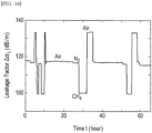
- the background gases X3, X4, X5, X6 have been used as target gases.
- the background gas has been changed in order of X6, X3, X5 and X4, as illustrated in Fig. 13 , and the leakage factor ⁇ L has been measured as illustrated in Fig. 14 . Since the measured gas parameters G* of the background gases X3, X4, X5, X6, listed in a table of Fig.
- the gas analyzer it is also possible to measure a concentration of the sensing gas in the background gas with high precision using the viscoelastic factor ⁇ V , even when composition of the background gas is changed.
- the leakage factor ⁇ L evaluated using Eq. (4) and the viscoelastic factor ⁇ V evaluated using Eq. (15) have been compared in a wide time range of about 65 hours using humid gases having the frost points of -60°C, -50°C and -40°C, which correspond to 10.7 ppmv, 38.8 ppmv and -127 ppmv, as illustrated in Figs.
- the leakage factor ⁇ L is independent of the moisture content, as illustrated in Fig. 18 .
- the viscoelastic factor ⁇ V is almost independent on the change in the background composition and represents only the change in moisture content.
- the viscoelastic factor ⁇ V is useful for the moisture measurement under different background gases without time-consuming recalibration procedure for each background gas.
- each of M(bar), G(bar), ⁇ (bar) , C p (bar) and C v (bar), etc. represents a symbol labeled with an horizontal over line, or an over bar on the top of the characters of M, ⁇ , C p and C v , etc.
- x is the concentration by mole percentage, or mol%, of gas XA
- M A , C PA and C VA are molecular weight, specific heat at a constant pressure and specific heat at constant volume of the gas XA
- M B , C PB , C VB are molecular weight, specific heat at a constant pressure and specific heat at constant volume of the gas XB, respectively.
- the measured leakage factor ⁇ L in the measurement sequence is plotted against time in Fig. 21 .
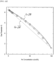
- the average gas parameter G(bar) has been calculated over the last ten minutes of each step, and plotted by open circles against the He concentration in Fig. 22 .
- the measured values of the average gas parameter G(bar) agree well with a calculated curve, illustrated by solid curve in Fig. 22 , using Eq. (19) with parameters listed in Fig. 20 .
- the concentration of He can be measured by the average gas parameter G(bar) with using a calibration curve.
- the calibration curve may be calculated by replacing C PB with ⁇ C PB and C VB with ⁇ C VB in Eq. (19) where the ⁇ is an adjustable parameter.
- the adjustable parameter ⁇ has no physical meaning, the adjustable parameter ⁇ helps to improve the agreement between the experimental data and the calibration curve when the adjustable parameter ⁇ is set to 3.0, as illustrated by dotted curve in Fig. 22 , which is slightly deformed and shifted from the solid curve.
- He concentration has been measured as illustrated in Fig. 23 , where set concentration has been increased in order from 0 mol% to 10 mol% by 2 mol% steps, decreased from 10 mol% to 0 mol% by 2 mol% steps, increased from 0 mol% to 100 mol% by 10 mol% steps and decreased from 100 mol% to 0 mol% by 10 mol% steps.
- the measured concentration has been compared with the set concentration and it has been confirmed that good agreement between the set concentration and measured concentration has been obtained as illustrated in Fig. 24 .
- the standard deviation of the measured concentration from the set concentration has been about 0.96% in the measurement of He 0 mol% to 100 mol%.
- the gas analyzer for checking whether an interior of a glove box has been replaced with a purge-gas.
- the glove box used for Li-ion batteries or for 3D printers of metal objects it is required to replace air and moisture in the glove box with the purge-gas.
- an inert gas such as argon, helium, N 2 and the like, or a mixture of inert gases may be preferably used to avoid unwanted chemical reactions with oxygen (O 2 ) in the air and the moisture.
- the purge-gas and the air may be implemented by the mix gas and concentration of the purge-gas may increase with time.
- concentration of the purge-gas as a component gas, which is mixed with the air in the glove box, using the gas parameter G(bar) of Eq. (19).
- concentration of the moisture in the glove box may be also measured as the sensing gas using the viscoelastic factor ⁇ V of Eq. (15).
- the average molecular weight M(bar) and the average specific heat ratio ⁇ (bar) are useful for calculation of many physical/chemical property of the mix gas.
- the gas analyzer can measure a sound velocity of the gas by the velocity measurement unit 18 using an ultrasonic wave having a frequency in a range of 10kHz to 100kHz.
- V bar 1 / ⁇ bar K G bar 1 / 2
- it is useful to express the average leaky attenuation coefficient ⁇ L (bar) as ⁇ L bar f ⁇ bar / K G bar 1 / 2 / ⁇ S V S 2 similarly to Eq. (1). Then, from Eqs.
- the average molecular weight and the average specific heat ratio can not be separated by merely measuring the average gas parameter. However, by adding measurement of the average sound velocity of the mix gas, it is possible to independently measure the average molecular weight and the average specific heat ratio. Thus, there is an advantage that other thermodynamic quantities can be calculated by independently measuring the average molecular weight and the average specific heat ratio.
Landscapes
- Physics & Mathematics (AREA)
- Chemical & Material Sciences (AREA)
- Health & Medical Sciences (AREA)
- Life Sciences & Earth Sciences (AREA)
- General Physics & Mathematics (AREA)
- Pathology (AREA)
- Biochemistry (AREA)
- General Health & Medical Sciences (AREA)
- Analytical Chemistry (AREA)
- Immunology (AREA)
- Acoustics & Sound (AREA)
- Engineering & Computer Science (AREA)
- Signal Processing (AREA)
- Combustion & Propulsion (AREA)
- Food Science & Technology (AREA)
- Medicinal Chemistry (AREA)
- Mathematical Analysis (AREA)
- Mathematical Optimization (AREA)
- Mathematical Physics (AREA)
- Pure & Applied Mathematics (AREA)
- Algebra (AREA)
- Investigating Or Analyzing Materials By The Use Of Ultrasonic Waves (AREA)
Claims (17)
- System zur Gasanalyse, Folgendes umfassend:
Sensor (1), der Folgendes umfasst:ein piezoelektrisches Substrat, das eine piezoelektrische Kugel (20) ist,eine Sensorelektrode (22), die konfiguriert ist, einen kollimierten Strahl (21) einer akustischen Oberflächenwelle erster, f1, und zweiter, f2, Frequenzen zu erzeugen, der sich auf der piezoelektrischen Kugel (20) ausbreitet, wobei f2 = nf1 und n 3 oder 5 ist, undeinen empfindlichen Film (23, 23a), der konfiguriert ist, ein in einem Hintergrundgas enthaltenes Sensorgas zu adsorbieren, wobei der empfindliche Film (23, 23a) auf der Kugel (20) an einer Stelle aufgetragen ist, an der der kollimierte Strahl (21) hindurchtritt; undeine Signalverarbeitungseinheit (40), die Folgendes umfasst:einen Signalgenerator (42a), der konfiguriert ist, ein Burstsignal an die Sensorelektrode (22) zu senden, um den kollimierten Strahl (21) zu erregen,einen Signalempfänger (42b), der konfiguriert ist, erste und zweite zurückgesendete Burstsignale des kollimierten Strahls (21) durch die Sensorelektrode (22) zu empfangen, nachdem sich der kollimierte Strahl (21) auf der piezoelektrischen Kugel (20) ausgebreitet hat, wobei das erste zurückgesendete Burstsignal die erste Frequenz und das zweite zurückgesendete Burstsignal die zweite Frequenz aufweist; undeinen Datenprozessor (44), der konfiguriert ist, einen Zielgasparameter durch einen Zielleckfaktor des Hintergrundgases und durch eine Beziehung zwischen Referenzgasparametern und Referenzleckfaktoren von Referenzgasen zu berechnen, wobei der Zielleckfaktor durch eine erste Dämpfung des ersten zurückgeführten Burstsignals und eine zweite Dämpfung des zweiten zurückgeführten Burstsignals unter Verwendung von Wellenformdaten des ersten und zweiten zurückgeführten Burstsignals bereitgestellt wird, wobei der Zielleckfaktor und der Zielgasparameter gegeben sind durch,
 ΔαL der Zielleckagefaktor und G ist der Zielgasparameter ist,f1 und f2 die erste bzw. zweite Frequenz ist,α1 und α2 die erste bzw. zweite Dämpfung ist,u eine reelle Zahl ist, die 1,8 ≦ u ≦ 2,3 genügt, und I eine Ausbreitungslänge der akustischen Oberflächenwelle ist,T und P die Temperatur bzw. der Druck des Hintergrundgases ist, undA und d ein Koeffizient bzw. ein Ausdruck ist, der durch einen Sensorausfall verursacht wird.
 - System nach Anspruch 1, wobei die Signalverarbeitungseinheit (40) Folgendes umfasst:eine Speichereinheit (48), die jeden der Referenzgasparameter als Quadratwurzel eines Produkts aus dem Molekulargewicht jedes der Referenzgase und einem Verhältnis der spezifischen Wärme bei konstantem Druck zu spezifischer Wärme bei konstantem Volumen jedes der Referenzgase speichert, undjeden der Referenzleckagefaktoren durch eine erste Referenzdämpfung eines ersten Referenzburstsignals und eine zweite Referenzdämpfung eines zweiten Referenzburstsignals unter Verwendung von Wellenformdaten eines Referenzburstsignals speichert.
- System nach Anspruch 1, wobei der Datenprozessor konfiguriert ist, den Zielgasparameter mit den Referenzgasparametern zu vergleichen, um eine Gasspezies des Hintergrundgases zu bewerten.
- System nach Anspruch 1, wobei der Datenprozessor konfiguriert ist, einen viskoelastischen Faktor des Hintergrundgases zu messen, um eine Konzentration des Sensorgases zu berechnen, wobei der viskoelastische Faktor durch die erste Dämpfung und die zweite Dämpfung bereitgestellt wird; wobei der viskoelastische Faktor gegeben ist durch:
 wobei Δαv als der viskoelastische Faktor gilt,f1 und f2 die erste bzw. zweite Frequenz ist,α1 und α2 die erste bzw. zweite Dämpfung ist,z eine reelle Zahl ist, die 0,8 ≦ z ≦ 1,3 erfüllt, und I eine Ausbreitungslänge der akustischen Oberflächenwelle ist.
 - System nach Anspruch 1, wobei die Signalverarbeitungseinheit (40) eine Speichereinheit (48) umfasst, die jeden der Referenzgasparameter als Quadratwurzel eines Produkts eines durchschnittlichen Molekulargewichts und eines Verhältnisses einer durchschnittlichen spezifischen Wärme bei konstantem Druck zu einer durchschnittlichen spezifischen Wärme bei konstantem Volumen jedes der Komponentengase speichert.
- System nach Anspruch 5, wobei der Datenprozessor (44) konfiguriert ist, eine Konzentration eines beliebigen der Komponentengase durch die Referenzgasparameter zu berechnen.
- System nach Anspruch 5, ferner umfassend eine Geschwindigkeitsmesseinheit (18), die konfiguriert ist, eine Schallgeschwindigkeit des Hintergrundgases zu messen, wobei der Datenprozessor (44) konfiguriert ist, einen mittleren Leckschwächungskoeffizienten durch den Zielleckfaktor und eine mittlere Schallgeschwindigkeit des Hintergrundgases, gemessen mit der Geschwindigkeitsmesseinheit, zu berechnen, und der Datenprozessor eine mittlere Kompressibilität des Hintergrundgases und eine mittlere Dichte des Hintergrundgases durch den mittleren Leckschwächungskoeffizienten und die mittlere Schallgeschwindigkeit berechnet.
- System nach Anspruch 7, wobei der Datenprozessor (44) konfiguriert ist, ferner ein mittleres Molekulargewicht und ein mittleres Verhältnis von spezifischer Wärme durch den mittleren Gasparameter und die mittlere Schallgeschwindigkeit zu berechnen.
- Verfahren zur Gasanalyse unter Verwendung eines akustischen Oberflächenwellensensors (2) mit einer Sensorelektrode (22), die eine akustische Oberflächenwelle erzeugt, und einem empfindlichen Film (23, 23a), der ein Sensorgas adsorbiert, auf einem piezoelektrischen Substrat (20), das eine piezoelektrische Kugel ist, Folgendes umfassend:Einleiten eines Gases, das das zu erfassende Gas enthält, als Hintergrund in eine Sensorzelle (31), in der sich der Oberflächenwellensensor (2) befindet;Übertragen eines anregenden Burstsignals an die Sensorelektrode (22), um einen kollimierten Strahl (21) der akustischen Oberflächenwelle erster, f1, und zweiter, f2, Frequenzen anzuregen, der sich auf dem piezoelektrischen Substrat (20) ausbreitet, während er durch den empfindlichen Film (23, 23a) hindurchgeht, der an einer Stelle aufgebracht ist, an der der kollimierte Strahl hindurchgeht, wobei f2 = nf1 und n 3 oder 5 ist;Empfangen des ersten und zweiten zurückgesendeten Burstsignals des kollimierten Strahls durch die Sensorelektrode (22), nachdem sich der kollimierte Strahl (21) auf dem piezoelektrischen Substrat (20) ausgebreitet hat, wobei das erste zurückgesendete Burstsignal die erste Frequenz und das zweite zurückgesendete Burstsignal die zweite Frequenz aufweist; undBerechnen eines Zielgasparameters durch einen Zielleckagefaktor des Hintergrundgases und einer Beziehung zwischen Referenzgasparametern und Referenzleckagefaktoren von Referenzgasen, wobei der Leckagefaktor durch eine erste Dämpfung des ersten rückgeführten Burstsignals und eine zweite Dämpfung des zweiten rückgeführten Burstsignals unter Verwendung von Wellenformdaten des ersten und zweiten rückgeführten Burstsignals bereitgestellt wird,wobei der Zielleckagefaktor und der Zielgasparameter gegeben sind durch,

 ΔαL der Zielleckagefaktor und G ist der Zielgasparameter ist,f1 und f2 die erste bzw. zweite Frequenz ist,α1 und α2 die erste bzw. zweite Dämpfung ist,u eine reelle Zahl ist, die 1,8 ≦ u ≦ 2,3 genügt, und I eine Ausbreitungslänge der akustischen Oberflächenwelle ist,T und P die Temperatur bzw. der Druck des Hintergrundgases ist, undA und d ein Koeffizient bzw. ein Ausdruck ist, der durch einen Sensorausfall verursacht wird.
 - Verfahren nach Anspruch 9, wobeijede der Referenzgasparameter als Quadratwurzel eines Produkts aus dem Molekulargewicht jedes der Referenzgase und einem Verhältnis der spezifischen Wärme bei konstantem Druck zu spezifischer Wärme bei konstantem Volumen jedes der Referenzgase bereitgestellt wird, undjeder der Referenzleckagefaktoren durch eine erste Referenzdämpfung eines ersten Referenzburstsignals und eine zweite Referenzdämpfung eines zweiten Referenzburstsignals unter Verwendung von Wellenformdaten eines Referenzburstsignals bereitsgestellt wird.
- Verfahren nach Anspruch 9, das ferner das Vergleichen des Zielgasparameters mit den Referenzgasparametern umfasst, um eine Gasspezies des Hintergrundgases zu bewerten.
- Verfahren nach Anspruch 10, das ferner das Messen eines viskoelastischen Faktors des Hintergrundgases umfasst, um eine Konzentration des Sensorgases zu berechnen, wobei der viskoelastische Faktor durch die erste Dämpfung und die zweite Dämpfung bereitgestellt wird; wobei der viskoelastische Faktor gegeben ist durch,
 wobei Δαv als der viskoelastische Faktor gilt,f1 und f2 die erste bzw. zweite Frequenz ist,α1 und α2 die erste bzw. zweite Dämpfung ist,z eine reelle Zahl ist, die 0,8 ≦ z ≦ 1,3 erfüllt, und I eine Ausbreitungslänge der akustischen Oberflächenwelle ist.
 - Verfahren nach Anspruch 9, wobeidas Hintergrundgas eine Vielzahl von Komponentengasen umfasst, undjeder der Referenzgasparameter als Quadratwurzel eines Produkts aus einem durchschnittlichen Molekulargewicht und einem Verhältnis einer durchschnittlichen spezifischen Wärme bei konstantem Druck zu einer durchschnittlichen spezifischen Wärme bei konstantem Volumen jedes der Komponentengase definiert ist.
- Verfahren nach Anspruch 13, wobei das Hintergrundgas ein Gemisch aus zwei Komponentengasen ist und ferner umfassend:
Berechnen einer Konzentration eines beliebigen der Komponentengase durch die Referenzgasparameter. - Verfahren nach Anspruch 9, ferner umfassend:Messen einer mittleren Schallgeschwindigkeit des Hintergrundgases unter Verwendung einer Geschwindigkeitsmesseinheit (18); undBerechnen einer mittleren Kompressibilität des Hintergrundgases und einer mittleren Dichte des Hintergrundgases durch einen mittleren Leckschwächungskoeffizienten und die mittlere Schallgeschwindigkeit.
- Verfahren nach Anspruch 15, das ferner das Berechnen eines mittleren Molekulargewichts und eines mittleren Verhältnisses von spezifischer Wärme durch den mittleren Gasparameter und die mittlere Schallgeschwindigkeit umfasst.
- Computerprogrammprodukt, enthalten auf einem computerlesbaren Medium für die Gasanalyse unter Verwendung eines Sensors für akustische Oberflächenwellen (2), der eine Sensorelektrode (22), die eine akustische Oberflächenwelle erzeugt, und einen empfindlichen Film (23, 23a), der ein Messgas adsorbiert, auf einem piezoelektrischen Substrat (20), das eine piezoelektrische Kugel ist, aufweist, wobei das Computerprogrammprodukt umfasst:Einleiten eines Gases, das das zu erfassende Gas enthält, als Hintergrund in eine Sensorzelle (31), in der sich der Oberflächenwellensensor (2) befindet;Anweisungen für das Übertragen eines anregenden Burstsignals an die Sensorelektrode (22), um einen kollimierten Strahl der akustischen Oberflächenwelle erster, f1, und zweiter, f2, Frequenzen anzuregen, der sich auf dem piezoelektrischen Substrat (20) ausbreitet, während er durch den empfindlichen Film (23, 23a) hindurchgeht, der an einer Stelle aufgebracht ist, an der der kollimierte Strahl (21) hindurchgeht, wobei f2 = nf1 und n 3 oder 5 ist;Anweisungen für das Empfangen des ersten und zweiten zurückgesendeten Burstsignals des kollimierten Strahls (21) durch die Sensorelektrode, nachdem sich der kollimierte Strahl (21) auf dem piezoelektrischen Substrat (20a) ausgebreitet hat, wobei das erste zurückgesendete Burstsignal die erste Frequenz und das zweite zurückgesendete Burstsignal die zweite Frequenz aufweist; undAnweisungen für das Berechnen eines Zielgasparameters durch einen Zielleckfaktor des Hintergrundgases und durch eine Beziehung zwischen Referenzgasparametern und Referenzleckfaktoren von Referenzgasen, wobei der Zielleckfaktor durch eine erste Dämpfung des ersten zurückgeführten Burstsignals und eine zweite Dämpfung des zweiten zurückgeführten Burstsignals unter Verwendung von Wellenformdaten des ersten und zweiten zurückgeführten Burstsignals bereitgestellt wird, wobei der Zielleckfaktor und der Zielgasparameter gegeben sind durch,

 ΔαL der Zielleckagefaktor und G ist der Zielgasparameter ist,f1 und f2 die erste bzw. zweite Frequenz ist,α1 und α2 die erste bzw. zweite Dämpfung ist,u eine reelle Zahl ist, die 1,8 ≦ u ≦ 2,3 genügt, und I eine Ausbreitungslänge der akustischen Oberflächenwelle ist,T und P Temperatur und Druck des Hintergrundgases sind, und A und d ein Koeffizient bzw. ein Ausdruck sind, der durch einen Sensorverlust verursacht wird.
Applications Claiming Priority (2)
| Application Number | Priority Date | Filing Date | Title |
|---|---|---|---|
| US201862624139P | 2018-01-31 | 2018-01-31 | |
| PCT/JP2019/003269 WO2019151362A1 (en) | 2018-01-31 | 2019-01-30 | System, method and computer program product for gas analysis |
Publications (3)
| Publication Number | Publication Date |
|---|---|
| EP3662278A1 EP3662278A1 (de) | 2020-06-10 |
| EP3662278A4 EP3662278A4 (de) | 2021-03-31 |
| EP3662278B1 true EP3662278B1 (de) | 2025-03-05 |
Family
ID=67478320
Family Applications (1)
| Application Number | Title | Priority Date | Filing Date |
|---|---|---|---|
| EP19748382.9A Active EP3662278B1 (de) | 2018-01-31 | 2019-01-30 | System, verfahren und computerprogrammprodukt zur gasanalyse |
Country Status (7)
| Country | Link |
|---|---|
| US (1) | US11313836B2 (de) |
| EP (1) | EP3662278B1 (de) |
| JP (1) | JP7057480B2 (de) |
| KR (1) | KR102399765B1 (de) |
| CN (1) | CN111094968B (de) |
| FI (1) | FI3662278T3 (de) |
| WO (1) | WO2019151362A1 (de) |
Families Citing this family (5)
| Publication number | Priority date | Publication date | Assignee | Title |
|---|---|---|---|---|
| JP7438051B2 (ja) * | 2020-07-31 | 2024-02-26 | 日立グローバルライフソリューションズ株式会社 | 光音響センサ、光音響センサの校正方法、及び空調システム |
| EP4194540A4 (de) * | 2020-08-17 | 2024-09-11 | Ball Wave Inc. | Virustestvorrichtung, virustestsystem, virustestverfahren und virustestprogramm |
| FR3114153B1 (fr) * | 2020-09-11 | 2025-04-18 | Agence Nat Pour La Gestion Des Dechets Radioactifs | dispositif et procédé d’identification d’une contamination gazeuse |
| FR3114152A1 (fr) * | 2020-09-11 | 2022-03-18 | Agence Nationale Pour La Gestion Des Dechets Radioactifs | Dispositif et procédé de détection d’hydrogène |
| KR102825697B1 (ko) * | 2024-11-22 | 2025-06-25 | 강정민 | 도시가스의 수소 혼입용 믹서 노즐장치 |
Family Cites Families (10)
| Publication number | Priority date | Publication date | Assignee | Title |
|---|---|---|---|---|
| US5076094A (en) * | 1990-10-03 | 1991-12-31 | The United States Of America As Represented By The United States Department Of Energy | Dual output acoustic wave sensor for molecular identification |
| JPH09210975A (ja) | 1996-01-30 | 1997-08-15 | Kurita Water Ind Ltd | ガス検出装置 |
| AU2002310031A1 (en) * | 2001-05-23 | 2002-12-03 | University Of Florida | Method and apparatus for detecting illicit substances |
| US20070041870A1 (en) * | 2003-03-26 | 2007-02-22 | Kazushi Yamanaka | Sensor head, gas sensor and sensor unit |
| JP4780771B2 (ja) * | 2006-05-17 | 2011-09-28 | 凸版印刷株式会社 | 匂いセンシングシステム |
| WO2008056458A1 (fr) * | 2006-11-10 | 2008-05-15 | Tohoku University | Analyseur de gaz et méthode d'analyse de gaz |
| JP5092490B2 (ja) | 2007-03-28 | 2012-12-05 | 凸版印刷株式会社 | 球状弾性表面波素子の複数周波数駆動計測装置 |
| WO2016084917A1 (ja) | 2014-11-28 | 2016-06-02 | 国立大学法人東北大学 | 電気信号処理装置 |
| CN105020591B (zh) * | 2015-06-17 | 2018-01-02 | 常州大学 | 一种城市燃气管道不开挖泄漏检测定位方法 |
| JP6805418B2 (ja) * | 2016-11-07 | 2020-12-23 | ボールウェーブ株式会社 | ガス濃度測定システム、ガス濃度測定方法及びガス濃度測定用コンピュータプログラム |
-
2019
- 2019-01-30 CN CN201980004546.5A patent/CN111094968B/zh active Active
- 2019-01-30 US US16/650,404 patent/US11313836B2/en active Active
- 2019-01-30 WO PCT/JP2019/003269 patent/WO2019151362A1/en not_active Ceased
- 2019-01-30 FI FIEP19748382.9T patent/FI3662278T3/fi active
- 2019-01-30 JP JP2020541474A patent/JP7057480B2/ja active Active
- 2019-01-30 KR KR1020207010802A patent/KR102399765B1/ko active Active
- 2019-01-30 EP EP19748382.9A patent/EP3662278B1/de active Active
Also Published As
| Publication number | Publication date |
|---|---|
| EP3662278A1 (de) | 2020-06-10 |
| KR20200053578A (ko) | 2020-05-18 |
| FI3662278T3 (fi) | 2025-05-15 |
| CN111094968B (zh) | 2022-09-06 |
| US20200225190A1 (en) | 2020-07-16 |
| JP2021511518A (ja) | 2021-05-06 |
| CN111094968A (zh) | 2020-05-01 |
| JP7057480B2 (ja) | 2022-04-20 |
| EP3662278A4 (de) | 2021-03-31 |
| KR102399765B1 (ko) | 2022-05-20 |
| US11313836B2 (en) | 2022-04-26 |
| WO2019151362A1 (en) | 2019-08-08 |
Similar Documents
| Publication | Publication Date | Title |
|---|---|---|
| EP3662278B1 (de) | System, verfahren und computerprogrammprodukt zur gasanalyse | |
| Cumpson et al. | The quartz crystal microbalance; radial/polar dependence of mass sensitivity both on and off the electrodes | |
| JP2007524853A (ja) | 層状表面弾性波センサ | |
| Mccann et al. | A lateral-field-excited LiTaO 3 high-frequency bulk acoustic wave sensor | |
| CN101198865A (zh) | 无线声学滤油器传感器 | |
| CN102625906A (zh) | 用于使用压电谐振器的流体介质中的纳米重量测定的方法和设备 | |
| WO2005095947A1 (ja) | 環境差異検出装置 | |
| Rabus et al. | High-overtone bulk-acoustic resonator gravimetric sensitivity: Towards wideband acoustic spectroscopy | |
| EP3545293B1 (de) | System, verfahren und computerprogrammprodukt zur messung der gaskonzentration | |
| US20050069864A1 (en) | Measurement method and biosensor apparatus using resonator | |
| Esmeryan et al. | Temperature behavior of solid polymer film coated quartz crystal microbalance for sensor applications | |
| EP3752814B1 (de) | Standardfeuchtigkeitsgenerator, system mit dem standardfeuchtigkeitsgenerator, verfahren zum erkennen von anomalien in standardfeuchtigkeit und computerprogrammprodukt zum erkennen der anomalie | |
| Dultsev et al. | QCM operating in threshold mode as a gas sensor | |
| US11307176B2 (en) | Standard-moisture generator, system using the standard-moisture generator, method for detecting abnormality in standard-moisture and computer program product for detecting the abnormality | |
| Fischerauer et al. | A simple model for the effect of nonuniform mass loading on the response of gravimetric chemical sensors | |
| Takeda et al. | Deep Sub-micro mol· mol-1 Water-Vapor Measurement by Dual-Ball SAW Sensors for Temperature Compensation | |
| KR102258668B1 (ko) | 레조네이터 검증 방법 | |
| Yoo et al. | Surface acoustic wave sensors to detect volatile gases by measuring output phase shift | |
| Matsuda et al. | Fast-response algorithm for calculating polyatomic gas concentration using ultrasound | |
| Kryshtal et al. | Sensors based on saw resonator with “nontraditional formats” of output signal | |
| Dey et al. | Design and Simulation of Portable Fuel Adulteration Detection Kit | |
| Moutoulas | Surface acoustic wave corrosion sensors for liquified natural gas tank monitoring | |
| Yamanaka et al. | Principle and application of ball SAW devices | |
| JP2006337314A (ja) | 物質検出装置 |
Legal Events
| Date | Code | Title | Description |
|---|---|---|---|
| STAA | Information on the status of an ep patent application or granted ep patent |
Free format text: STATUS: THE INTERNATIONAL PUBLICATION HAS BEEN MADE |
|
| PUAI | Public reference made under article 153(3) epc to a published international application that has entered the european phase |
Free format text: ORIGINAL CODE: 0009012 |
|
| STAA | Information on the status of an ep patent application or granted ep patent |
Free format text: STATUS: REQUEST FOR EXAMINATION WAS MADE |
|
| 17P | Request for examination filed |
Effective date: 20200303 |
|
| AK | Designated contracting states |
Kind code of ref document: A1 Designated state(s): AL AT BE BG CH CY CZ DE DK EE ES FI FR GB GR HR HU IE IS IT LI LT LU LV MC MK MT NL NO PL PT RO RS SE SI SK SM TR |
|
| AX | Request for extension of the european patent |
Extension state: BA ME |
|
| A4 | Supplementary search report drawn up and despatched |
Effective date: 20210303 |
|
| RIC1 | Information provided on ipc code assigned before grant |
Ipc: G01N 29/24 20060101ALI20210225BHEP Ipc: G01N 29/02 20060101AFI20210225BHEP Ipc: G01N 29/44 20060101ALI20210225BHEP |
|
| DAV | Request for validation of the european patent (deleted) | ||
| DAX | Request for extension of the european patent (deleted) | ||
| STAA | Information on the status of an ep patent application or granted ep patent |
Free format text: STATUS: EXAMINATION IS IN PROGRESS |
|
| 17Q | First examination report despatched |
Effective date: 20230803 |
|
| GRAP | Despatch of communication of intention to grant a patent |
Free format text: ORIGINAL CODE: EPIDOSNIGR1 |
|
| STAA | Information on the status of an ep patent application or granted ep patent |
Free format text: STATUS: GRANT OF PATENT IS INTENDED |
|
| INTG | Intention to grant announced |
Effective date: 20241108 |
|
| GRAS | Grant fee paid |
Free format text: ORIGINAL CODE: EPIDOSNIGR3 |
|
| GRAA | (expected) grant |
Free format text: ORIGINAL CODE: 0009210 |
|
| STAA | Information on the status of an ep patent application or granted ep patent |
Free format text: STATUS: THE PATENT HAS BEEN GRANTED |
|
| AK | Designated contracting states |
Kind code of ref document: B1 Designated state(s): AL AT BE BG CH CY CZ DE DK EE ES FI FR GB GR HR HU IE IS IT LI LT LU LV MC MK MT NL NO PL PT RO RS SE SI SK SM TR |
|
| REG | Reference to a national code |
Ref country code: GB Ref legal event code: FG4D |
|
| REG | Reference to a national code |
Ref country code: CH Ref legal event code: EP |
|
| REG | Reference to a national code |
Ref country code: IE Ref legal event code: FG4D |
|
| REG | Reference to a national code |
Ref country code: DE Ref legal event code: R096 Ref document number: 602019066879 Country of ref document: DE |
|
| REG | Reference to a national code |
Ref country code: FI Ref legal event code: FGE |
|
| PG25 | Lapsed in a contracting state [announced via postgrant information from national office to epo] |
Ref country code: RS Free format text: LAPSE BECAUSE OF FAILURE TO SUBMIT A TRANSLATION OF THE DESCRIPTION OR TO PAY THE FEE WITHIN THE PRESCRIBED TIME-LIMIT Effective date: 20250605 |
|
| REG | Reference to a national code |
Ref country code: NL Ref legal event code: MP Effective date: 20250305 |
|
| PG25 | Lapsed in a contracting state [announced via postgrant information from national office to epo] |
Ref country code: ES Free format text: LAPSE BECAUSE OF FAILURE TO SUBMIT A TRANSLATION OF THE DESCRIPTION OR TO PAY THE FEE WITHIN THE PRESCRIBED TIME-LIMIT Effective date: 20250305 |
|
| REG | Reference to a national code |
Ref country code: LT Ref legal event code: MG9D |
|
| PG25 | Lapsed in a contracting state [announced via postgrant information from national office to epo] |
Ref country code: NO Free format text: LAPSE BECAUSE OF FAILURE TO SUBMIT A TRANSLATION OF THE DESCRIPTION OR TO PAY THE FEE WITHIN THE PRESCRIBED TIME-LIMIT Effective date: 20250605 |
|
| PG25 | Lapsed in a contracting state [announced via postgrant information from national office to epo] |
Ref country code: HR Free format text: LAPSE BECAUSE OF FAILURE TO SUBMIT A TRANSLATION OF THE DESCRIPTION OR TO PAY THE FEE WITHIN THE PRESCRIBED TIME-LIMIT Effective date: 20250305 |
|
| PG25 | Lapsed in a contracting state [announced via postgrant information from national office to epo] |
Ref country code: LV Free format text: LAPSE BECAUSE OF FAILURE TO SUBMIT A TRANSLATION OF THE DESCRIPTION OR TO PAY THE FEE WITHIN THE PRESCRIBED TIME-LIMIT Effective date: 20250305 |
|
| PG25 | Lapsed in a contracting state [announced via postgrant information from national office to epo] |
Ref country code: GR Free format text: LAPSE BECAUSE OF FAILURE TO SUBMIT A TRANSLATION OF THE DESCRIPTION OR TO PAY THE FEE WITHIN THE PRESCRIBED TIME-LIMIT Effective date: 20250606 Ref country code: BG Free format text: LAPSE BECAUSE OF FAILURE TO SUBMIT A TRANSLATION OF THE DESCRIPTION OR TO PAY THE FEE WITHIN THE PRESCRIBED TIME-LIMIT Effective date: 20250305 |
|
| REG | Reference to a national code |
Ref country code: AT Ref legal event code: MK05 Ref document number: 1773327 Country of ref document: AT Kind code of ref document: T Effective date: 20250305 |
|
| PG25 | Lapsed in a contracting state [announced via postgrant information from national office to epo] |
Ref country code: NL Free format text: LAPSE BECAUSE OF FAILURE TO SUBMIT A TRANSLATION OF THE DESCRIPTION OR TO PAY THE FEE WITHIN THE PRESCRIBED TIME-LIMIT Effective date: 20250305 |
|
| PG25 | Lapsed in a contracting state [announced via postgrant information from national office to epo] |
Ref country code: SE Free format text: LAPSE BECAUSE OF FAILURE TO SUBMIT A TRANSLATION OF THE DESCRIPTION OR TO PAY THE FEE WITHIN THE PRESCRIBED TIME-LIMIT Effective date: 20250305 |
|
| PG25 | Lapsed in a contracting state [announced via postgrant information from national office to epo] |
Ref country code: SM Free format text: LAPSE BECAUSE OF FAILURE TO SUBMIT A TRANSLATION OF THE DESCRIPTION OR TO PAY THE FEE WITHIN THE PRESCRIBED TIME-LIMIT Effective date: 20250305 |
|
| PG25 | Lapsed in a contracting state [announced via postgrant information from national office to epo] |
Ref country code: PT Free format text: LAPSE BECAUSE OF FAILURE TO SUBMIT A TRANSLATION OF THE DESCRIPTION OR TO PAY THE FEE WITHIN THE PRESCRIBED TIME-LIMIT Effective date: 20250707 |
|
| PG25 | Lapsed in a contracting state [announced via postgrant information from national office to epo] |
Ref country code: IT Free format text: LAPSE BECAUSE OF FAILURE TO SUBMIT A TRANSLATION OF THE DESCRIPTION OR TO PAY THE FEE WITHIN THE PRESCRIBED TIME-LIMIT Effective date: 20250305 Ref country code: PL Free format text: LAPSE BECAUSE OF FAILURE TO SUBMIT A TRANSLATION OF THE DESCRIPTION OR TO PAY THE FEE WITHIN THE PRESCRIBED TIME-LIMIT Effective date: 20250305 |
|
| PG25 | Lapsed in a contracting state [announced via postgrant information from national office to epo] |
Ref country code: AT Free format text: LAPSE BECAUSE OF FAILURE TO SUBMIT A TRANSLATION OF THE DESCRIPTION OR TO PAY THE FEE WITHIN THE PRESCRIBED TIME-LIMIT Effective date: 20250305 |
|
| PG25 | Lapsed in a contracting state [announced via postgrant information from national office to epo] |
Ref country code: CZ Free format text: LAPSE BECAUSE OF FAILURE TO SUBMIT A TRANSLATION OF THE DESCRIPTION OR TO PAY THE FEE WITHIN THE PRESCRIBED TIME-LIMIT Effective date: 20250305 Ref country code: EE Free format text: LAPSE BECAUSE OF FAILURE TO SUBMIT A TRANSLATION OF THE DESCRIPTION OR TO PAY THE FEE WITHIN THE PRESCRIBED TIME-LIMIT Effective date: 20250305 |
|
| PG25 | Lapsed in a contracting state [announced via postgrant information from national office to epo] |
Ref country code: RO Free format text: LAPSE BECAUSE OF FAILURE TO SUBMIT A TRANSLATION OF THE DESCRIPTION OR TO PAY THE FEE WITHIN THE PRESCRIBED TIME-LIMIT Effective date: 20250305 |
|
| PG25 | Lapsed in a contracting state [announced via postgrant information from national office to epo] |
Ref country code: SK Free format text: LAPSE BECAUSE OF FAILURE TO SUBMIT A TRANSLATION OF THE DESCRIPTION OR TO PAY THE FEE WITHIN THE PRESCRIBED TIME-LIMIT Effective date: 20250305 |
|
| PG25 | Lapsed in a contracting state [announced via postgrant information from national office to epo] |
Ref country code: IS Free format text: LAPSE BECAUSE OF FAILURE TO SUBMIT A TRANSLATION OF THE DESCRIPTION OR TO PAY THE FEE WITHIN THE PRESCRIBED TIME-LIMIT Effective date: 20250705 |
|
| REG | Reference to a national code |
Ref country code: DE Ref legal event code: R097 Ref document number: 602019066879 Country of ref document: DE |
|
| PLBE | No opposition filed within time limit |
Free format text: ORIGINAL CODE: 0009261 |
|
| STAA | Information on the status of an ep patent application or granted ep patent |
Free format text: STATUS: NO OPPOSITION FILED WITHIN TIME LIMIT |
|
| PG25 | Lapsed in a contracting state [announced via postgrant information from national office to epo] |
Ref country code: DK Free format text: LAPSE BECAUSE OF FAILURE TO SUBMIT A TRANSLATION OF THE DESCRIPTION OR TO PAY THE FEE WITHIN THE PRESCRIBED TIME-LIMIT Effective date: 20250305 |
|
| PGFP | Annual fee paid to national office [announced via postgrant information from national office to epo] |
Ref country code: FI Payment date: 20251224 Year of fee payment: 8 |
|
| REG | Reference to a national code |
Ref country code: CH Ref legal event code: L10 Free format text: ST27 STATUS EVENT CODE: U-0-0-L10-L00 (AS PROVIDED BY THE NATIONAL OFFICE) Effective date: 20260114 |
|
| 26N | No opposition filed |
Effective date: 20251208 |