EP3659834A2 - Dispositif palier pour un compresseur d'air d'un véhicule - Google Patents
Dispositif palier pour un compresseur d'air d'un véhicule Download PDFInfo
- Publication number
- EP3659834A2 EP3659834A2 EP19203283.7A EP19203283A EP3659834A2 EP 3659834 A2 EP3659834 A2 EP 3659834A2 EP 19203283 A EP19203283 A EP 19203283A EP 3659834 A2 EP3659834 A2 EP 3659834A2
- Authority
- EP
- European Patent Office
- Prior art keywords
- air
- bearing device
- compressed air
- air compressor
- bearing
- Prior art date
- Legal status (The legal status is an assumption and is not a legal conclusion. Google has not performed a legal analysis and makes no representation as to the accuracy of the status listed.)
- Withdrawn
Links
Images


Classifications
-
- B—PERFORMING OPERATIONS; TRANSPORTING
- B60—VEHICLES IN GENERAL
- B60G—VEHICLE SUSPENSION ARRANGEMENTS
- B60G11/00—Resilient suspensions characterised by arrangement, location or kind of springs
- B60G11/26—Resilient suspensions characterised by arrangement, location or kind of springs having fluid springs only, e.g. hydropneumatic springs
- B60G11/27—Resilient suspensions characterised by arrangement, location or kind of springs having fluid springs only, e.g. hydropneumatic springs wherein the fluid is a gas
-
- B—PERFORMING OPERATIONS; TRANSPORTING
- B60—VEHICLES IN GENERAL
- B60G—VEHICLE SUSPENSION ARRANGEMENTS
- B60G17/00—Resilient suspensions having means for adjusting the spring or vibration-damper characteristics, for regulating the distance between a supporting surface and a sprung part of vehicle or for locking suspension during use to meet varying vehicular or surface conditions, e.g. due to speed or load
- B60G17/02—Spring characteristics, e.g. mechanical springs and mechanical adjusting means
- B60G17/04—Spring characteristics, e.g. mechanical springs and mechanical adjusting means fluid spring characteristics
- B60G17/052—Pneumatic spring characteristics
- B60G17/0521—Pneumatic spring characteristics the spring having a flexible wall
-
- B—PERFORMING OPERATIONS; TRANSPORTING
- B60—VEHICLES IN GENERAL
- B60G—VEHICLE SUSPENSION ARRANGEMENTS
- B60G17/00—Resilient suspensions having means for adjusting the spring or vibration-damper characteristics, for regulating the distance between a supporting surface and a sprung part of vehicle or for locking suspension during use to meet varying vehicular or surface conditions, e.g. due to speed or load
- B60G17/02—Spring characteristics, e.g. mechanical springs and mechanical adjusting means
- B60G17/04—Spring characteristics, e.g. mechanical springs and mechanical adjusting means fluid spring characteristics
- B60G17/052—Pneumatic spring characteristics
- B60G17/0523—Regulating distributors or valves for pneumatic springs
- B60G17/0526—Distributor units, e.g. for retractable wheels
-
- B—PERFORMING OPERATIONS; TRANSPORTING
- B60—VEHICLES IN GENERAL
- B60G—VEHICLE SUSPENSION ARRANGEMENTS
- B60G2202/00—Indexing codes relating to the type of spring, damper or actuator
- B60G2202/10—Type of spring
- B60G2202/15—Fluid spring
- B60G2202/152—Pneumatic spring
-
- B—PERFORMING OPERATIONS; TRANSPORTING
- B60—VEHICLES IN GENERAL
- B60G—VEHICLE SUSPENSION ARRANGEMENTS
- B60G2204/00—Indexing codes related to suspensions per se or to auxiliary parts
- B60G2204/10—Mounting of suspension elements
- B60G2204/20—Mounting of accessories, e.g. pump, compressor
-
- B—PERFORMING OPERATIONS; TRANSPORTING
- B60—VEHICLES IN GENERAL
- B60G—VEHICLE SUSPENSION ARRANGEMENTS
- B60G2400/00—Indexing codes relating to detected, measured or calculated conditions or factors
- B60G2400/50—Pressure
- B60G2400/51—Pressure in suspension unit
- B60G2400/512—Pressure in suspension unit in spring
- B60G2400/5122—Fluid spring
- B60G2400/51222—Pneumatic
-
- B—PERFORMING OPERATIONS; TRANSPORTING
- B60—VEHICLES IN GENERAL
- B60G—VEHICLE SUSPENSION ARRANGEMENTS
- B60G2500/00—Indexing codes relating to the regulated action or device
- B60G2500/20—Spring action or springs
- B60G2500/203—Distributor valve units comprising several elements, e.g. valves, pump or accumulators
-
- B—PERFORMING OPERATIONS; TRANSPORTING
- B60—VEHICLES IN GENERAL
- B60G—VEHICLE SUSPENSION ARRANGEMENTS
- B60G2500/00—Indexing codes relating to the regulated action or device
- B60G2500/20—Spring action or springs
- B60G2500/205—Air-compressor operation
-
- F—MECHANICAL ENGINEERING; LIGHTING; HEATING; WEAPONS; BLASTING
- F16—ENGINEERING ELEMENTS AND UNITS; GENERAL MEASURES FOR PRODUCING AND MAINTAINING EFFECTIVE FUNCTIONING OF MACHINES OR INSTALLATIONS; THERMAL INSULATION IN GENERAL
- F16F—SPRINGS; SHOCK-ABSORBERS; MEANS FOR DAMPING VIBRATION
- F16F15/00—Suppression of vibrations in systems; Means or arrangements for avoiding or reducing out-of-balance forces, e.g. due to motion
- F16F15/02—Suppression of vibrations of non-rotating, e.g. reciprocating systems; Suppression of vibrations of rotating systems by use of members not moving with the rotating systems
- F16F15/023—Suppression of vibrations of non-rotating, e.g. reciprocating systems; Suppression of vibrations of rotating systems by use of members not moving with the rotating systems using fluid means
- F16F15/027—Suppression of vibrations of non-rotating, e.g. reciprocating systems; Suppression of vibrations of rotating systems by use of members not moving with the rotating systems using fluid means comprising control arrangements
- F16F15/0275—Control of stiffness
-
- F—MECHANICAL ENGINEERING; LIGHTING; HEATING; WEAPONS; BLASTING
- F16—ENGINEERING ELEMENTS AND UNITS; GENERAL MEASURES FOR PRODUCING AND MAINTAINING EFFECTIVE FUNCTIONING OF MACHINES OR INSTALLATIONS; THERMAL INSULATION IN GENERAL
- F16F—SPRINGS; SHOCK-ABSORBERS; MEANS FOR DAMPING VIBRATION
- F16F2230/00—Purpose; Design features
- F16F2230/18—Control arrangements
- F16F2230/183—Control arrangements fluid actuated
-
- F—MECHANICAL ENGINEERING; LIGHTING; HEATING; WEAPONS; BLASTING
- F16—ENGINEERING ELEMENTS AND UNITS; GENERAL MEASURES FOR PRODUCING AND MAINTAINING EFFECTIVE FUNCTIONING OF MACHINES OR INSTALLATIONS; THERMAL INSULATION IN GENERAL
- F16F—SPRINGS; SHOCK-ABSORBERS; MEANS FOR DAMPING VIBRATION
- F16F9/00—Springs, vibration-dampers, shock-absorbers, or similarly-constructed movement-dampers using a fluid or the equivalent as damping medium
- F16F9/02—Springs, vibration-dampers, shock-absorbers, or similarly-constructed movement-dampers using a fluid or the equivalent as damping medium using gas only or vacuum
- F16F9/04—Springs, vibration-dampers, shock-absorbers, or similarly-constructed movement-dampers using a fluid or the equivalent as damping medium using gas only or vacuum in a chamber with a flexible wall
Definitions
- the present invention relates to a bearing device of an air compressor of a vehicle, by means of which the air compressor is connected to a body of the vehicle in a vibration-isolating manner.
- An air compressor in a vehicle is used to provide compressed air for a variety of pneumatic tasks.
- wheel suspensions are equipped with pneumatic wheel springs, which are also referred to as air springs, in order to set a different spring characteristic depending on the driving situation and the desired vehicle behavior.
- decoupling devices for the air compressor of a vehicle are therefore necessary, one or more such decoupling devices being arranged between a body of the vehicle and the air compressor.
- the decoupling devices have the task of isolating or damping natural vibrations of the air compressor from a body in such a way that structure-borne sound propagation of the air compressor is largely suppressed.
- the decoupling device transfers as few dynamic forces as possible that are generated by the air compressor during operation into the body.
- shocks and vibrations of the body are isolated from the air compressor or only passed on to it in a dampened manner, so that is exposed to reduced external shock loads and can therefore achieve a longer service life.
- bearing devices with spiral springs are known from the prior art as decoupling devices, and a high degree of decoupling of the compressor from the vehicle can be achieved via the spiral springs with a low spring stiffness.
- the problem arises that the air compressor constantly encounters limiting elements during travel or the decoupling or spring device transmits shocks and vibrations, so that the working noises in the body are acoustically noticeable and noise is thus generated.
- an undesirable resonance behavior of the decoupling device can result at certain speeds of the air compressor, which leads to increased noise.
- the vibration decoupling can be used for suspending vibration-generating machines, such as motors on a surface, for example a vehicle chassis.
- the bearing is based on the principle of an air spring.
- This vibration decoupling comprises a rubber body in which compressed air is enclosed. This ensures that the vibration decoupling is as equally effective as possible in all directions and can be subjected to the same load in all directions.
- the vibration decoupling comprises a ring on which a groove is attached, with which different variants of connectors can be clicked in.
- the EP 3 181 944 A1 discloses a vibration isolator used to store semiconductor industry devices.
- the vibration isolator is included a work space designed as an air spring and has a base part and a head part. The base and head part are connected to a load to be insulated.
- the air spring consists of an outer housing and an inner housing, both housings being sealed with one another via an elastic membrane.
- a magnetic actuator consisting of coils and magnets is provided for an insulation effect in the vertical direction.
- a bending rod is provided, which is connected to the head part by a screw and to the inner housing by a screw.
- a pressure in the work area can be regulated via a pneumatic control valve, and the work area can move in the vertical direction due to the elasticity of the membrane.
- the German utility model DE 78 17 348 U introduces a rubber-elastic bearing that includes a hollow rubber spring, a plate valve, a mounting flange and metal end walls.
- the end wall is connected to a motor housing on the motor side and the end wall is arranged facing away from the motor, the end walls being rigidly connected to one another by a centrally provided bolt.
- two chambers are separated by the plate valve, into which a liquid is filled. The chambers are connected to one another via valve openings of the plate valve.
- the GB 2 124 731 A shows an inflatable vibration damper comprising two annular elements.
- a gas, a liquid or a combination of a gas and a liquid can be filled into the annular elements.
- a spring of the vibration damper can be replaced by another ring-shaped element or a soft rubber element.
- the vibration damper can be used for a heavy machine, for example a diesel engine, to dampen the vibrations during operation.
- each air spring is arranged between a mounting of the engine and a mounting of the body 38, the air spring being made of rubber.
- the air springs are connected on one side to the body and on the other side to the engine to dampen the vibrations of the engine .
- the US 5,018,698 A shows a vibration-isolating holder for a pump, with which the vibrations of the pump occurring during operation can be reduced. Vibrations of an air compressor in relation to a body cannot be reduced in this way.
- the JP S59-13 698 A represents a device comprising an air compressor and an air tank, wherein the compressed air generated by the air compressor can be admitted into the air tank.
- an air spring is attached to a bottom of the air tank. Accordingly, an air spring for damping a moving wheel is arranged on the body.
- a bearing device for an air compressor with a body of a vehicle is proposed, by means of which the air compressor is connected to a body of a vehicle in a vibration-isolating manner.
- the bearing device comprises at least one air spring with an elastic air bellows, the air bellows being connected to a compressed air line of the air compressor for controllable compressed air filling.
- an air spring having an elastic air bellows is proposed, the air bellows preferably being made of rubber or a flexible, flexible material, wherein the rigidity of the bearing device can be changed by the elasticity and the introduced air pressure volume of the air bellows.
- Vibration-isolating property means that the air bellows has a higher rigidity when unpressurized and therefore has less vibration isolation.
- the bearing device consisting of at least one air spring is provided for decoupling the air compressor from the body.
- the bearing device is arranged between the air compressor and the body. During operation of the air compressor, no noise is generated due to impacts between the air compressor and the limiting elements surrounding the coil springs.
- the use of the bearing device which is connected on one side to the air compressor and on the other side to the body, can reduce the transmission of dynamic forces into the body and thus better decoupling can be achieved.
- the air bellows has a connection for connecting to a compressed air line of a mounted air compressor, which preferably provides compressed air for a vehicle suspension.
- the air bellows can thus be filled and inflated with compressed air via the compressed air line during operation of the air compressor.
- a valve contained in the compressed air line can be controlled via a control device such as an electronic unit, the valve being controlled in the open position when inflated. Uncontrolled inflation during operation and a depressurized state in the idle state of the air compressor can enable relatively simple adaptive storage.
- the air bellows is connected to a compressed air accumulator of a vehicle suspension system via a compressed air line.
- the excess compressed air generated by the air compressor is introduced into the compressed air reservoir via another pressure line, so that the compressed air reservoir can be inflated.
- the air bellows can be connected to the compressed air reservoir and thus the compressed air can be directed into the air bellows.
- a valve can be present in the compressed air line connected to the air bellows, the valve being able to be controlled by the control device. The valve can be adjusted between an open position and a closed position as required. As a result, the air bellows can be inflated and blown out in a controllable manner.
- the bearing device can comprise a plurality of air springs, in particular three or more, each air spring each having an elastic air bellows.
- the air compressor is connected to the body exclusively by air springs. Different types of position devices with a different number of air springs can be used for different air compressors to reduce the transmission of force when the air compressor vibrates.
- the air spring can be formed at least in two stages and preferably comprise an upper plate and a lower plate, the upper plate and the lower plate being respectively arranged on an upper part and lower part of the air bellows.
- the upper plate and the lower plate can be made of a dimensionally stable, hard material, for example made of metal or plastic, and can in each case be fastened to an upper end face and a lower end face of the air bellows with different connection options, for example by gluing. If the valve arranged on the air bellows is switched off, the air compressor can be lifted out of an elastic seat which is formed from the elastic air bellows.
- the air bellows can be completely filled with the compressed air, so that the air compressor can be decoupled from the body via the air spring formed.
- the air bellows advantageously has a self-resetting initial shape in which the two plates lie opposite one another and the air bellows material in between provides a reduced decoupling property.
- the two-stage air spring can be in a mechanically defined starting position in the idle state.
- a position of the two-stage air spring can be designed as the starting position if there is no air in the air bellows.
- the air compressor can be mounted on the elastic material of the air bellows, whereby a mechanical tight fit - at least in a preferred direction vertically between the body and the air compressor - can be achieved between the upper part and the lower part of the air bellows.
- the upper plate - due to a self-resetting spring action of the air bellows material - can engage mechanically in a form-fitting manner in the lower plate as soon as the air bellows is depressurized, so that the air compressor moves in a horizontal direction between the air compressor and the body is mechanically fixed and a spring tension is exerted by the air bellows wall in the vertical direction as the preferred direction from the air compressor to the body.
- a compressed air line can be provided for connecting the air bellows to the atmosphere via the valve, the compressed air line on one side, ie. h on one side, be connected to the connection of the air bellows and the air bellows on the other side, d.
- the pressureless air bellows can be provided. This can result in a horizontal tight fit of the air bellows, so that in the idle state the bearing of the air compressor is fixed in the horizontal direction between the air compressor and the body and is mounted relatively stiffly.
- a spring tension from the material of the air bellows is provided in the vertical direction from the air compressor to the body. With the spring tension, the air compressor can be stored sufficiently decoupled from the body in the idle state.
- the lower plate can have at least one recess and the upper plate has at least one complementary projection, the projection and the recess preferably being formed in the central region of the corresponding plate.
- the top and bottom plates are used to attach the air compressor to the body.
- fastening holes can be provided in the edge region of both plates, for example, through which screws or rivets for fastening the upper plate and lower plate can be guided accordingly on the air compressor and the body.
- the projection can be complementary to the inner profile of the recess, so that the upper plate can be inserted into the lower plate in a mechanically fixed manner.
- the inner surface portion of the air bladder with respect to the protrusion of the upper plate can contact the inner surface portion of the air bladder with respect to the recess of the lower plate.
- the air spring can be in a mechanically fixed starting position.
- a resilient mounting can be formed both in the horizontal direction and in the vertical direction in the operating state by pressurizing the air bellows.
- the valve can be controlled by the control device and be in the open position, so that the compressed air compressed by the air compressor can be guided through the compressed air line to the air bellows.
- the more compressed air there is in the air bellows the greater the spring tension that can be provided by the air spring.
- a complete storage of the air bellows enables a soft bearing to be achieved, which is formed both in the horizontal direction and in the vertical direction, so that undesired vibrations or structure-borne noise can be optimally reduced by operating the air compressor.
- An increase in the air pressure can lead to an increase in the spring stiffness and a decrease in the air pressure to a decrease in the spring stiffness, so that different stiffness values can be achieved on the basis of the air pressure.
- a controllable bearing directional control valve can be connected to the two-stage air spring.
- a 3/2-way valve can be arranged as a storage directional control valve, so that the storage directional control valve can be switched to different switching positions for pressurization, pressure relief and pressure locking.
- the storage directional control valve can be arranged on the air bellows via a connecting line, the compressed air being able to be provided either by the air compressor or by the compressed air reservoir via the pressure line. This provides a stepless regulation of the rigidity.
- controllable bearing directional control valve can activate the air spring before activating the air compressor.
- a hysteresis over time can thereby be formed, wherein the activation of the air bearing or the activation of the air compressor can be achieved before switching on and a deflation of the air spring after switching off the air compressor in order to suppress start-up and discharge noises of the air compressor.
- the air compressor can be stored in air before the air compressor starts. Suppression of working noises can be ensured in a particularly advantageous manner since different types of starting noises of the air compressor can also be compensated for.
- a control unit can be set up to draw compressed air from a compressed air reservoir for activating the air spring before activation of the air compressor and to actuate the controllable storage directional control valve upstream and / or afterwards, in particular to release the air spring afterwards.
- the compressed air reservoir can, for example, be an additional compressed air tank or an already existing compressed air tank.
- compressed air from a compressed air reservoir in particular from a compressed air line of the vehicle, from an air spring for a wheel, from a compressed air connection system of the vehicle, from a compressed air reservoir and / or from an additional compressed air reservoir, can be supplied to the air spring by the controllable bearing directional control valve .
- the compressed air can therefore be obtained from different air sources.
- the compressed air feeds to the air compressor can preferably be switched off or blocked at the time at which compressed air is supplied to the air spring as described above. Additional valves can be provided for this.
- the air spring can be filled with compressed air for 1-10 seconds, in particular 2-5 seconds, before the air compressor is activated, or depressurized after the air compressor has been switched off.
- the periods just described can also be less than 1 second.
- the bearing directional control valve can be electrically controllable.
- the bearing directional control valve is also referred to as an electrically operated valve.
- the storage directional control valve can be connected to an electrical connection of the control device.
- the bearing directional control valve can be actuated in such a way that an electromagnet as an actuating element can be actuated with the electrical voltage and the switching of the valve can thus be initiated.
- the storage directional control valve can be controlled electrically and no complicated mechanical connection or extensive pneumatic pilot controls are provided to actuate the storage directional control valve.
- the use of an electrically operated valve can lead to a significantly easier installation at lower costs.
- the bearing directional control valve can be controlled pneumatically.
- the storage valve is called a pneumatic valve.
- a connection for the compressed air is provided instead of an electrical connection, and the bearing directional control valve can be switched by means of a control compressed air of the air pressure system.
- a pneumatic valve enables a low cost and there is no need for additional electrical components that are at risk of failure.
- the storage directional control valve can have two connections, a first connection being connected to the compressed air outlet of the air compressor or to a compressed air outlet of a compressed air store, a second connection being connected to the atmosphere via an outlet line.
- a first switching position and a second switching position are provided. If the storage valve is switched to the first switching position, the air bellows can be filled with the compressed air generated directly by the air compressor or the compressed air received in the compressed air reservoir depending on the connection, so that the air spring can be in the operating state. If the storage valve is switched to the second switching position, the compressed air in the air bellows can be blown out to the atmosphere via the outlet line, so that the air spring can be in the idle state. This enables simple pressure control of an adjustable spring stiffness.
- a vibration sensor can be arranged on the compressor for monitoring the vibration of the air compressor, wherein a variable amount of the compressed air guided into the air bellows can be regulated via the bearing directional control valve according to the vibration intensity of the air compressor.
- the vibration sensor can be connected to an electrical connection of the control device, wherein the vibration sensor can detect the vibration intensity of the air compressor and can generate a vibration signal responsive to it.
- the vibration signal is sent to the control device and thus the control device controls the storage directional control valve in order to switch the storage directional control valve to an open position or a closed position.
- the amount of compressed air in the air bellows can be changed according to the vibration level of the air compressor and, if necessary, correlated with it via a characteristic curve.
- the vibration sensor can be used to provide an adaptive suspension property of the bearing device, in particular one or more adapted air springs for different vibration levels of the air compressor, so that an improved decoupling of the air compressor is made possible.
- compressed air adapted for this can be introduced into the air bellows.
- This does not necessarily have to be a maximum compressed air strength, but can e.g. based on the characteristic curve, a quantity of compressed air that provides optimum spring stiffness for decoupling. In this way, an optimal decoupling of the air compressor can be achieved.
- a pressure sensor for detecting the air pressure in the air bellows and for generating a pressure signal responsive thereto can be included, the pressure sensor being arranged at the inlet of the air bellows.
- the pressure sensor can be arranged in the connection channel between the air spring and the bearing directional control valve in order to detect the air pressure at a compressed air inlet or compressed air outlet of the air bellows.
- the pressure sensor can pass on its signal to a connection of the control device, so that the pressure signal is transmitted to the control device and the storage directional control valve can hereby be controlled adaptively by the control device.
- a pressure sensor is advantageously arranged on the compressed air inlet of the air bellows and a vibration sensor on the air compressor.
- An error message can be output with the two sensors, whereby even with adjusted air pressure in the air bellows, e.g. to suppress resonance, the air compressor vibrates unexpectedly strongly. This means that if an unexpected vibration occurs, an error can be determined by the two sensors in combination.
- a quantity of the compressed air in the air bellows can be changed in a controllable manner via the storage directional valve.
- the pressure sensor can detect the air pressure in the air bellows in real time; the amount of compressed air can hereby be changed according to the pressure strength via the bearing directional control valve, which can be controlled by the control device.
- the air compressor can thus be optimally decoupled during operation.
- an air compressor of a vehicle which is connected to a body of a vehicle in a vibration-isolating manner by means of a bearing device as described above.
- the air compressor according to the invention comprises a bearing device according to one of the aforementioned exemplary embodiments.
- Such a bearing device can also be used advantageously as a spare part for replacing or further developing an air compressor.
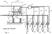
- FIG. 1 schematically shows a compressed air supply device 10 with a bearing device known from the prior art, which consists of three spiral springs 46, of which only two are visible in the illustration.
- the compressed air supply device 10 has an air compressor 20 which comprises a motor-operated air pressure cylinder, preferably a two-stage air pressure cylinder, which is connected to a feed line 11 on the intake side.
- a check valve 18 is provided in the feed line 11, which opens in the suction direction and towards the air compressor 20 and closes in opposite directions by means of spring loading.
- An air dryer 24 is arranged in a pressure line 12 with the pressure side of the air compressor 20.
- a 2/2-way valve 26 is arranged as the first directional valve 26
- a 3/2-way valve 30 as the second way valve 30 via a pressure line 12 with a pneumatic Control input 28 of the first directional valve 26 is connected.
- the pneumatic control input 28 of the first directional valve 26 is connected to the atmosphere by the second directional valve 30 via a connecting line 32.
- each air spring for a wheel 40 of a vehicle is connected to a pressure line 12, in which a 2/2-way valve 38 is arranged as a third directional valve 38, the control input of which is connected to a control device 16 via a control line 14.
- the suspension characteristic of the vehicle wheel can be set via the control line 14.
- a compressed air reservoir 36 is switched on in a pressure line 12, a 2/2-way valve 34 being arranged as a changeover valve 34 at the compressed air inlet of the compressed air reservoir 36.
- a housing 42 comprising the air compressor 20 can be connected to a body 44 of a vehicle.
- the spiral springs 46 are intended to achieve mechanical decoupling of the body, so that vibrations occurring during operation are passed on to the body in a reduced manner. Adjusting the spring characteristics is not possible.
- a compressed air supply device 10 according to a first embodiment of a bearing device 76 according to the invention is shown schematically.
- a housing 42 comprising an air compressor 20 can be connected to a body 44 of a vehicle by the bearing device 76, the bearing device 76 being connected via a pressure line 12 to a 3/2-way valve 50 as a bearing directional valve 50.
- Compressed air can be introduced or removed into the pneumatically operated bearing device 76 via the storage directional control valve 50, so that a spring characteristic of the bearing device 76 can be set depending on the operating state of the air compressor 20.
- the storage directional control valve 50 has a first connection 68 and a second connection 70. Compressed air can be blown out of the bearing device 76 to the atmosphere via an outlet line 66.
- compressed air can be supplied, for example, from the pressure line 12, from the compressed air reservoir 36 and / or from the air spring 40 for a wheel of the air spring 48. While compressed air is supplied to the air spring 48 from at least one of the compressed air sources 12, 36 or 40, the connections of the air spring 48 to the other compressed air sources 12, 36 or 40 can be switched off. For this purpose, for example, further valves can be provided in the system. It is still conceivable to do more Feed compressed air from an additional compressed air reservoir, for example an additional, rechargeable compressed air cartridge (not shown) to the air spring 48.
- the control of the supply of compressed air into the air spring 48 before the activation of the air compressor 20 or the control of the discharge of compressed air after the deactivation of the air compressor 20 can be carried out by a control unit (not shown).
- a motor-operated air pressure cylinder of the air compressor 12 is connected to a feed line 11 on the intake side.
- a check valve 18 is provided in front of the air compressor 20.
- An air dryer 24 is arranged in the pressure line 12 with the pressure side of the air compressor 20. Between the air compressor 20 and the air dryer 24, a 2/2-way valve 26 is provided as the first directional valve 26 in a branch, a 3/2-way valve 30 as the second directional valve 30 via a pressure line 12 to a pneumatic control input 28 of the first directional valve 26 connected.
- the compressed air generated by the compressed air supply device 10 can be fed via a pressure line 12 into four air springs for wheels 40, each air spring 40 being connected to a 2/2-way valve 38, the control input of which is connected to a control device 16 via a control line 14. Furthermore, a compressed air reservoir 36 is provided in a pressure line 12, a 2/2-way valve 34 being arranged as a changeover valve 34 at the compressed air inlet of the compressed air reservoir 36.
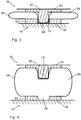
- FIG. 3 and 4 is a side view of the in Fig. 2 bearing device 76 shown in detail accordingly in the idle state ( Fig. 3 ) and in the operating state ( Fig. 4 ) shown.
- the bearing device 76 comprises an upper plate 60 and a lower plate 62 and an air spring 48 with an air bellows 58, the upper plate 60 having a projection 74 and the lower plate 62 having a shape-complementary recess 64.
- An upper part 54 of the bearing device 76 and a lower part 56 of the bearing device 76 can correspondingly be connected to the air compressor 20 and the body 44.
- a decoupling of the air compressor 20 can be achieved by the bearing device 76 both in the idle state and in the operating state.
- the bearing device 76 is in the idle state, in which the upper plate 50 engages in a mechanically positive manner in a damping direction vertically between the body 44 and the air compressor 20 in the lower plate 62. This can result in a horizontal tight fit of the air compressor 20 in the idle state, and in the vertical direction a rigid mounting of the air compressor 20 is brought about by a self-elastic property of the unpressurized air bellows 58.
- Fig. 4 represents the bearing device 76 in the operating state, wherein compressed air can be introduced into the air spring 48 or the air bellows 58 via the recess 64, so that an effective decoupling of the air compressor 20 from the body 44 can be achieved via the air spring 48.
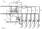
- Fig. 5 schematically shows a compressed air supply device 10 with a second embodiment of a bearing device 76, through which a housing 42 of an air compressor 20 can be connected to a body 44.
- An air compressor 20, an air dryer 24, a 2/2-way valve 26 as a first directional valve 26 and a 3/2-way valve 30 as a second directional valve 30 are arranged in the housing 42, the second directional valve 30 via a pressure line 12 to a pneumatic control input 28 of the first directional valve 26 is connected.
- a check valve 18 is provided in front of the air compressor 20.
- the compressed air generated by the air compressor 20 can be fed into four air springs for wheels 40, wherein a quantity of the compressed air in each air spring for wheel 40 can be controlled by a 2/2-way valve 38 which is designed as a third directional valve 38.
- a control input of the third directional valve 38 is connected to a control device 16 via a control line 14.
- a compressed air reservoir 36 is provided in a pressure line 12, a 2/2-way valve 34 being arranged as a changeover valve 34 at the compressed air inlet of the compressed air reservoir 36.
- a 3/2-way valve serving as a bearing directional valve 50 between the bearing device 76 and the compressed air reservoir 36 is used, which has a first connection 68 and a second connection 70.
- the compressed air can be blown out of the bearing device 76 to the atmosphere via an outlet line 66.
- a vibration sensor 52 is arranged on the housing 42, the vibration sensor 52 being connected to the control device 16, so that vibration signals can be transmitted to the control device 16.
- an air pressure can be set via the bearing directional valve 50 in the bearing device 76 to control the damper characteristic.
- the Fig. 6 illustrates schematically a compressed air supply device 10 with a third embodiment of a bearing device 76.
- An air compressor 20 is arranged in a housing 42.
- An air dryer 24 is provided with the pressure side of the air compressor 20 in a pressure line 12.
- a check valve 17 is arranged in front of the air compressor 20.
- the output side of the air compressor 20 is connected to a 2/2-way valve 26, a second 3/2-way valve 30 being connected to a pneumatic control input 28 of the 2/2-way valve 26.
- the compressed air can be fed via a pressure line 12 into four air springs for wheels 40, whereby a quantity of the compressed air in the air springs for wheels 40 can be changed by a 2/2-way valve 38.
- a control input of the 2/2-way valve 38 is connected to a control device 16 via a control line 14.
- the bearing device 76 is connected to the air compressor 20 via a pressure line 12, so that the compressed air can be provided by the air compressor 20 for the bearing device 76.
- a 3/2-way valve 50 can be used to regulate a variable amount of compressed air in the bearing device 76, which is designed as a bearing directional valve 50.
- a vibration sensor 52 is provided for the bearing device 76.
- the pressure sensor 72 is set up to increase the pressure prevailing in the air bellows 58 determine.
- the vibration sensor 52 is arranged on the housing 42 and the pressure sensor 72 at the compressed air inlet of the bearing device 76 in order to monitor on the one hand a vibration level of the air compressor 20 and on the other hand an air pressure in the bearing device 76.
- an error message can be output with the two sensors if an unexpected vibration occurs.
- the sensor signals of both sensors 52, 72 can be used to improve the position control of the air compressor 20 relative to the body 44.
- the two sensors 52, 72 are connected to the control device 16, so that vibration signals and pressure signals of the control device 16 can be monitored in order to optimize the damping stiffness of the bearing device 76 and to be able to carry out an error monitoring.
Landscapes
- Engineering & Computer Science (AREA)
- Mechanical Engineering (AREA)
- Vehicle Body Suspensions (AREA)
- Compressor (AREA)
Applications Claiming Priority (1)
| Application Number | Priority Date | Filing Date | Title |
|---|---|---|---|
| DE102018125503.9A DE102018125503A1 (de) | 2018-10-15 | 2018-10-15 | Lagervorrichtung für einen Luftkompressor eines Fahrzeugs |
Publications (2)
| Publication Number | Publication Date |
|---|---|
| EP3659834A2 true EP3659834A2 (fr) | 2020-06-03 |
| EP3659834A3 EP3659834A3 (fr) | 2020-08-12 |
Family
ID=68281050
Family Applications (1)
| Application Number | Title | Priority Date | Filing Date |
|---|---|---|---|
| EP19203283.7A Withdrawn EP3659834A3 (fr) | 2018-10-15 | 2019-10-15 | Dispositif palier pour un compresseur d'air d'un véhicule |
Country Status (2)
| Country | Link |
|---|---|
| EP (1) | EP3659834A3 (fr) |
| DE (2) | DE102018125503A1 (fr) |
Cited By (1)
| Publication number | Priority date | Publication date | Assignee | Title |
|---|---|---|---|---|
| CN113898695A (zh) * | 2021-09-30 | 2022-01-07 | 深圳中科飞测科技股份有限公司 | 一种隔振装置的启动控制方法、装置及自动隔振设备 |
Citations (16)
| Publication number | Priority date | Publication date | Assignee | Title |
|---|---|---|---|---|
| DE7817348U1 (de) | 1978-06-09 | 1978-10-19 | Boge Gmbh, 5208 Eitorf | Gummielastisches Lager |
| EP0049741A1 (fr) | 1980-10-10 | 1982-04-21 | Boge GmbH | Support axial élastique |
| JPS5913698A (ja) | 1982-07-14 | 1984-01-24 | Semiconductor Res Found | ZnSeのエピタキシヤル成長法及び成長装置 |
| GB2124731A (en) | 1982-06-22 | 1984-02-22 | Gordon Lloyd Pumphrey | Inflatable anti-vibration mounting |
| JPS59175641A (ja) | 1983-03-25 | 1984-10-04 | Hino Motors Ltd | 車両に使用されるエンジン・マウント |
| US4564177A (en) | 1983-04-21 | 1986-01-14 | The Firestone Tire & Rubber Company | Clamp for non-beaded pneumatic assemblies |
| US5018698A (en) | 1989-09-29 | 1991-05-28 | Jaromir Tobias | Motor vehicle vibration isolation support mounting system |
| JPH06227309A (ja) | 1993-02-02 | 1994-08-16 | Shin Caterpillar Mitsubishi Ltd | サービスカー |
| JPH08296558A (ja) | 1995-04-26 | 1996-11-12 | Nippondenso Co Ltd | 圧縮機の防振支持構造 |
| DE29817737U1 (de) | 1998-10-05 | 1999-01-07 | Sixt Margit | Fahrzeugservice-Einrichtung |
| US6123325A (en) | 1998-05-26 | 2000-09-26 | The Goodyear Tire & Rubber Company | Airtight end retainer for an airspring |
| DE102006025055A1 (de) | 2006-05-26 | 2007-11-29 | Linke, Sander | Multi-Direktionaler Schwingungsentkoppler |
| EP1979177A1 (fr) | 2006-08-08 | 2008-10-15 | SAF-HOLLAND GmbH | Ressort pneumatique pour un véhicule |
| US20150345490A1 (en) | 2012-12-13 | 2015-12-03 | Wabco Gmbh | Compressor for Producing Compressed Air, Compressed Air Supply System, Pneumatic System and Method for Operating a Compressor |
| DE102016224081A1 (de) | 2015-12-03 | 2017-06-08 | Continental Teves Ag & Co. Ohg | Luftfeder mit einem integrierten Luftverdichter |
| EP3181944A1 (fr) | 2015-12-16 | 2017-06-21 | Integrated Dynamics Engineering GmbH | Isolateur de vibrations doté d'un ressort pneumatique vertical |
Family Cites Families (16)
| Publication number | Priority date | Publication date | Assignee | Title |
|---|---|---|---|---|
| JPS5913692U (ja) * | 1982-07-19 | 1984-01-27 | トキコ株式会社 | 空気圧縮機 |
| DE10006024C1 (de) * | 2000-02-11 | 2001-10-25 | Continental Ag | Verfahren zum Auffüllen einer Druckmittelkammer einer Niveauregelanlage aus einem Druckmittelspeicher |
| JP2002019475A (ja) * | 2000-07-07 | 2002-01-23 | Toyota Motor Corp | 車載エンジンの懸架装置 |
| EP1243447B1 (fr) * | 2001-03-24 | 2005-12-21 | Continental Aktiengesellschaft | Dispositif fermé de réglage du niveau pour véhicules |
| DE10122567C1 (de) * | 2001-05-10 | 2002-11-21 | Continental Ag | Verfahren zur Regelung des Speicherdruckes in einer geschlossenen Niveauregelanlage |
| AT501224A1 (de) * | 2003-07-15 | 2006-07-15 | Siemens Sgp Verkehrstech Gmbh | Zentrierende notfederabstützung |
| DE102005045269A1 (de) * | 2005-09-22 | 2007-03-29 | Continental Aktiengesellschaft | Verfahren und Vorrichtung zur Erkennung von Leckagen in einer Kraftfahrzeug-Luftfederanordnung |
| DE102006005459A1 (de) * | 2006-02-07 | 2007-08-09 | Continental Aktiengesellschaft | Luftfeder mit Außenführung |
| SE531808C2 (sv) * | 2007-10-26 | 2009-08-11 | Scania Cv Abp | Förfarande för att uppskatta tillförd mängd tryckluft till en luftbälg i ett fordon |
| FI123240B (fi) * | 2011-04-19 | 2012-12-31 | Waertsilae Finland Oy | Järjestely ja menetelmä polttomoottorin suuntauksen säilyttämiseksi sekä menetelmä polttomoottorin suuntaamiseksi ja sen suuntauksen säilyttämiseksi |
| US10138972B2 (en) * | 2013-10-07 | 2018-11-27 | Sumitomo Electric Industries, Ltd. | Air spring and carriage for vehicle |
| EP3172070B1 (fr) * | 2014-07-21 | 2018-06-27 | Firestone Industrial Products Company, LLC | Ensembles d'élément d'extrémité, ainsi qu'ensembles de ressort à gaz et systèmes de suspension les comprenant |
| JP6486629B2 (ja) * | 2014-09-05 | 2019-03-20 | 株式会社ブリヂストン | 空気ばね装置 |
| JP2016070503A (ja) * | 2014-09-30 | 2016-05-09 | 株式会社フコク | 防振支持装置及びエアスプリングの製造方法 |
| EP3495176B1 (fr) * | 2015-03-27 | 2020-03-18 | Haldex Brake Products Aktiebolag | Dispositif de commande et installation de compression d'air de véhicule utilitaire |
| DE102016223707A1 (de) * | 2016-11-29 | 2018-05-30 | Audi Ag | Lageranordnung für ein Fahrzeug sowie Verfahren zur Steuerung einer solchen Lageranordnung |
-
2018
- 2018-10-15 DE DE102018125503.9A patent/DE102018125503A1/de active Pending
-
2019
- 2019-10-15 EP EP19203283.7A patent/EP3659834A3/fr not_active Withdrawn
- 2019-10-15 DE DE202019005587.8U patent/DE202019005587U1/de active Active
Patent Citations (16)
| Publication number | Priority date | Publication date | Assignee | Title |
|---|---|---|---|---|
| DE7817348U1 (de) | 1978-06-09 | 1978-10-19 | Boge Gmbh, 5208 Eitorf | Gummielastisches Lager |
| EP0049741A1 (fr) | 1980-10-10 | 1982-04-21 | Boge GmbH | Support axial élastique |
| GB2124731A (en) | 1982-06-22 | 1984-02-22 | Gordon Lloyd Pumphrey | Inflatable anti-vibration mounting |
| JPS5913698A (ja) | 1982-07-14 | 1984-01-24 | Semiconductor Res Found | ZnSeのエピタキシヤル成長法及び成長装置 |
| JPS59175641A (ja) | 1983-03-25 | 1984-10-04 | Hino Motors Ltd | 車両に使用されるエンジン・マウント |
| US4564177A (en) | 1983-04-21 | 1986-01-14 | The Firestone Tire & Rubber Company | Clamp for non-beaded pneumatic assemblies |
| US5018698A (en) | 1989-09-29 | 1991-05-28 | Jaromir Tobias | Motor vehicle vibration isolation support mounting system |
| JPH06227309A (ja) | 1993-02-02 | 1994-08-16 | Shin Caterpillar Mitsubishi Ltd | サービスカー |
| JPH08296558A (ja) | 1995-04-26 | 1996-11-12 | Nippondenso Co Ltd | 圧縮機の防振支持構造 |
| US6123325A (en) | 1998-05-26 | 2000-09-26 | The Goodyear Tire & Rubber Company | Airtight end retainer for an airspring |
| DE29817737U1 (de) | 1998-10-05 | 1999-01-07 | Sixt Margit | Fahrzeugservice-Einrichtung |
| DE102006025055A1 (de) | 2006-05-26 | 2007-11-29 | Linke, Sander | Multi-Direktionaler Schwingungsentkoppler |
| EP1979177A1 (fr) | 2006-08-08 | 2008-10-15 | SAF-HOLLAND GmbH | Ressort pneumatique pour un véhicule |
| US20150345490A1 (en) | 2012-12-13 | 2015-12-03 | Wabco Gmbh | Compressor for Producing Compressed Air, Compressed Air Supply System, Pneumatic System and Method for Operating a Compressor |
| DE102016224081A1 (de) | 2015-12-03 | 2017-06-08 | Continental Teves Ag & Co. Ohg | Luftfeder mit einem integrierten Luftverdichter |
| EP3181944A1 (fr) | 2015-12-16 | 2017-06-21 | Integrated Dynamics Engineering GmbH | Isolateur de vibrations doté d'un ressort pneumatique vertical |
Cited By (1)
| Publication number | Priority date | Publication date | Assignee | Title |
|---|---|---|---|---|
| CN113898695A (zh) * | 2021-09-30 | 2022-01-07 | 深圳中科飞测科技股份有限公司 | 一种隔振装置的启动控制方法、装置及自动隔振设备 |
Also Published As
| Publication number | Publication date |
|---|---|
| EP3659834A3 (fr) | 2020-08-12 |
| DE102018125503A1 (de) | 2020-04-16 |
| DE202019005587U1 (de) | 2021-02-24 |
Similar Documents
| Publication | Publication Date | Title |
|---|---|---|
| EP2780607B1 (fr) | Ressort pneumatique | |
| WO2015165912A1 (fr) | Agencement d'un amortisseur de vibrations associé à une roue d'un véhicule | |
| DE102014109191B4 (de) | Federungssystem für Fahrzeugsitze und Verfahren zum Federn von Fahrzeugsitzteilen | |
| DE102013016078A1 (de) | Feder-Dämpfer-System zur Verwendung in Lagern oder als Dämpfer | |
| EP0775844A2 (fr) | Support | |
| EP3487718A1 (fr) | Système de ressort et d'amortissement destiné à une motocyclette | |
| EP0480460A1 (fr) | Méthode de variation de la rigidité d'un support en élastomère et du support correspondant | |
| WO2006136452A1 (fr) | Systeme et procede pour creer un logement compensateur pour un organe | |
| EP1063446B1 (fr) | Amortisseur à air | |
| EP3659834A2 (fr) | Dispositif palier pour un compresseur d'air d'un véhicule | |
| WO2015075270A1 (fr) | Élément de palier fortement amorti | |
| DE102014211954A1 (de) | Hydrolager sowie Kraftfahrzeug mit einem derartigen Hydrolager | |
| DE2652501A1 (de) | Elastisches lager | |
| EP2820322B1 (fr) | Palier hydraulique | |
| DE102005004928B4 (de) | Hydrolager | |
| DE102014101090B4 (de) | Stromabnehmer-Feder-Dämpfer-Baueinheit | |
| DE102012001655A1 (de) | Hydraulisch dämpfendes Lager für ein Fahrwerk eines Fahrzeuges, insbesondere eines Kraftfahrzeugs, sowie Verfahren zur Veränderung der Position eines Fahrwerklagers | |
| DE102008057577A1 (de) | Elastomer-Lager und Verfahren zur Variation seiner Federsteifigkeit | |
| DE102020211178A1 (de) | Vorrichtung zur Dämpfung von Druckpulsationen und/oder Volumenstromschwankungen in einer Druckmittelströmung und Hydraulikaggregat für eine elektronisch schlupfregelbare Bremsanlage eines Kraftfahrzeugs mit einer derartigen Vorrichtung | |
| DE10137760C2 (de) | Luftlager | |
| EP1785291B1 (fr) | Jambe de suspension pour amortisseur d'un véhicule | |
| DE10330877A1 (de) | Fahrwerkslager | |
| DE102011055707A1 (de) | Federbein | |
| DE102008050084B3 (de) | Verfahren zur Schwingungsdämpfung und Schwingungsdämpfer | |
| DE102014226092A1 (de) | Hydrolager sowie Kraftfahrzeug mit einem derartigen Hydrolager |
Legal Events
| Date | Code | Title | Description |
|---|---|---|---|
| PUAI | Public reference made under article 153(3) epc to a published international application that has entered the european phase |
Free format text: ORIGINAL CODE: 0009012 |
|
| STAA | Information on the status of an ep patent application or granted ep patent |
Free format text: STATUS: THE APPLICATION HAS BEEN PUBLISHED |
|
| AK | Designated contracting states |
Kind code of ref document: A2 Designated state(s): AL AT BE BG CH CY CZ DE DK EE ES FI FR GB GR HR HU IE IS IT LI LT LU LV MC MK MT NL NO PL PT RO RS SE SI SK SM TR |
|
| AX | Request for extension of the european patent |
Extension state: BA ME |
|
| PUAL | Search report despatched |
Free format text: ORIGINAL CODE: 0009013 |
|
| AK | Designated contracting states |
Kind code of ref document: A3 Designated state(s): AL AT BE BG CH CY CZ DE DK EE ES FI FR GB GR HR HU IE IS IT LI LT LU LV MC MK MT NL NO PL PT RO RS SE SI SK SM TR |
|
| AX | Request for extension of the european patent |
Extension state: BA ME |
|
| RIC1 | Information provided on ipc code assigned before grant |
Ipc: F16F 15/023 20060101ALI20200706BHEP Ipc: F16F 15/027 20060101ALI20200706BHEP Ipc: B60G 11/27 20060101AFI20200706BHEP Ipc: B60G 17/052 20060101ALI20200706BHEP Ipc: F16F 9/02 20060101ALI20200706BHEP |
|
| STAA | Information on the status of an ep patent application or granted ep patent |
Free format text: STATUS: THE APPLICATION IS DEEMED TO BE WITHDRAWN |
|
| 18D | Application deemed to be withdrawn |
Effective date: 20210213 |