EP3659834A2 - Storage device for an air compressor of a vehicle - Google Patents
Storage device for an air compressor of a vehicle Download PDFInfo
- Publication number
- EP3659834A2 EP3659834A2 EP19203283.7A EP19203283A EP3659834A2 EP 3659834 A2 EP3659834 A2 EP 3659834A2 EP 19203283 A EP19203283 A EP 19203283A EP 3659834 A2 EP3659834 A2 EP 3659834A2
- Authority
- EP
- European Patent Office
- Prior art keywords
- air
- bearing device
- compressed air
- air compressor
- bearing
- Prior art date
- Legal status (The legal status is an assumption and is not a legal conclusion. Google has not performed a legal analysis and makes no representation as to the accuracy of the status listed.)
- Withdrawn
Links
Images


Classifications
-
- B—PERFORMING OPERATIONS; TRANSPORTING
- B60—VEHICLES IN GENERAL
- B60G—VEHICLE SUSPENSION ARRANGEMENTS
- B60G11/00—Resilient suspensions characterised by arrangement, location or kind of springs
- B60G11/26—Resilient suspensions characterised by arrangement, location or kind of springs having fluid springs only, e.g. hydropneumatic springs
- B60G11/27—Resilient suspensions characterised by arrangement, location or kind of springs having fluid springs only, e.g. hydropneumatic springs wherein the fluid is a gas
-
- B—PERFORMING OPERATIONS; TRANSPORTING
- B60—VEHICLES IN GENERAL
- B60G—VEHICLE SUSPENSION ARRANGEMENTS
- B60G17/00—Resilient suspensions having means for adjusting the spring or vibration-damper characteristics, for regulating the distance between a supporting surface and a sprung part of vehicle or for locking suspension during use to meet varying vehicular or surface conditions, e.g. due to speed or load
- B60G17/02—Spring characteristics, e.g. mechanical springs and mechanical adjusting means
- B60G17/04—Spring characteristics, e.g. mechanical springs and mechanical adjusting means fluid spring characteristics
- B60G17/052—Pneumatic spring characteristics
- B60G17/0521—Pneumatic spring characteristics the spring having a flexible wall
-
- B—PERFORMING OPERATIONS; TRANSPORTING
- B60—VEHICLES IN GENERAL
- B60G—VEHICLE SUSPENSION ARRANGEMENTS
- B60G17/00—Resilient suspensions having means for adjusting the spring or vibration-damper characteristics, for regulating the distance between a supporting surface and a sprung part of vehicle or for locking suspension during use to meet varying vehicular or surface conditions, e.g. due to speed or load
- B60G17/02—Spring characteristics, e.g. mechanical springs and mechanical adjusting means
- B60G17/04—Spring characteristics, e.g. mechanical springs and mechanical adjusting means fluid spring characteristics
- B60G17/052—Pneumatic spring characteristics
- B60G17/0523—Regulating distributors or valves for pneumatic springs
- B60G17/0526—Distributor units, e.g. for retractable wheels
-
- B—PERFORMING OPERATIONS; TRANSPORTING
- B60—VEHICLES IN GENERAL
- B60G—VEHICLE SUSPENSION ARRANGEMENTS
- B60G2202/00—Indexing codes relating to the type of spring, damper or actuator
- B60G2202/10—Type of spring
- B60G2202/15—Fluid spring
- B60G2202/152—Pneumatic spring
-
- B—PERFORMING OPERATIONS; TRANSPORTING
- B60—VEHICLES IN GENERAL
- B60G—VEHICLE SUSPENSION ARRANGEMENTS
- B60G2204/00—Indexing codes related to suspensions per se or to auxiliary parts
- B60G2204/10—Mounting of suspension elements
- B60G2204/20—Mounting of accessories, e.g. pump, compressor
-
- B—PERFORMING OPERATIONS; TRANSPORTING
- B60—VEHICLES IN GENERAL
- B60G—VEHICLE SUSPENSION ARRANGEMENTS
- B60G2400/00—Indexing codes relating to detected, measured or calculated conditions or factors
- B60G2400/50—Pressure
- B60G2400/51—Pressure in suspension unit
- B60G2400/512—Pressure in suspension unit in spring
- B60G2400/5122—Fluid spring
- B60G2400/51222—Pneumatic
-
- B—PERFORMING OPERATIONS; TRANSPORTING
- B60—VEHICLES IN GENERAL
- B60G—VEHICLE SUSPENSION ARRANGEMENTS
- B60G2500/00—Indexing codes relating to the regulated action or device
- B60G2500/20—Spring action or springs
- B60G2500/203—Distributor valve units comprising several elements, e.g. valves, pump or accumulators
-
- B—PERFORMING OPERATIONS; TRANSPORTING
- B60—VEHICLES IN GENERAL
- B60G—VEHICLE SUSPENSION ARRANGEMENTS
- B60G2500/00—Indexing codes relating to the regulated action or device
- B60G2500/20—Spring action or springs
- B60G2500/205—Air-compressor operation
-
- F—MECHANICAL ENGINEERING; LIGHTING; HEATING; WEAPONS; BLASTING
- F16—ENGINEERING ELEMENTS AND UNITS; GENERAL MEASURES FOR PRODUCING AND MAINTAINING EFFECTIVE FUNCTIONING OF MACHINES OR INSTALLATIONS; THERMAL INSULATION IN GENERAL
- F16F—SPRINGS; SHOCK-ABSORBERS; MEANS FOR DAMPING VIBRATION
- F16F15/00—Suppression of vibrations in systems; Means or arrangements for avoiding or reducing out-of-balance forces, e.g. due to motion
- F16F15/02—Suppression of vibrations of non-rotating, e.g. reciprocating systems; Suppression of vibrations of rotating systems by use of members not moving with the rotating systems
- F16F15/023—Suppression of vibrations of non-rotating, e.g. reciprocating systems; Suppression of vibrations of rotating systems by use of members not moving with the rotating systems using fluid means
- F16F15/027—Suppression of vibrations of non-rotating, e.g. reciprocating systems; Suppression of vibrations of rotating systems by use of members not moving with the rotating systems using fluid means comprising control arrangements
- F16F15/0275—Control of stiffness
-
- F—MECHANICAL ENGINEERING; LIGHTING; HEATING; WEAPONS; BLASTING
- F16—ENGINEERING ELEMENTS AND UNITS; GENERAL MEASURES FOR PRODUCING AND MAINTAINING EFFECTIVE FUNCTIONING OF MACHINES OR INSTALLATIONS; THERMAL INSULATION IN GENERAL
- F16F—SPRINGS; SHOCK-ABSORBERS; MEANS FOR DAMPING VIBRATION
- F16F2230/00—Purpose; Design features
- F16F2230/18—Control arrangements
- F16F2230/183—Control arrangements fluid actuated
-
- F—MECHANICAL ENGINEERING; LIGHTING; HEATING; WEAPONS; BLASTING
- F16—ENGINEERING ELEMENTS AND UNITS; GENERAL MEASURES FOR PRODUCING AND MAINTAINING EFFECTIVE FUNCTIONING OF MACHINES OR INSTALLATIONS; THERMAL INSULATION IN GENERAL
- F16F—SPRINGS; SHOCK-ABSORBERS; MEANS FOR DAMPING VIBRATION
- F16F9/00—Springs, vibration-dampers, shock-absorbers, or similarly-constructed movement-dampers using a fluid or the equivalent as damping medium
- F16F9/02—Springs, vibration-dampers, shock-absorbers, or similarly-constructed movement-dampers using a fluid or the equivalent as damping medium using gas only or vacuum
- F16F9/04—Springs, vibration-dampers, shock-absorbers, or similarly-constructed movement-dampers using a fluid or the equivalent as damping medium using gas only or vacuum in a chamber with a flexible wall
Definitions
- the present invention relates to a bearing device of an air compressor of a vehicle, by means of which the air compressor is connected to a body of the vehicle in a vibration-isolating manner.
- An air compressor in a vehicle is used to provide compressed air for a variety of pneumatic tasks.
- wheel suspensions are equipped with pneumatic wheel springs, which are also referred to as air springs, in order to set a different spring characteristic depending on the driving situation and the desired vehicle behavior.
- decoupling devices for the air compressor of a vehicle are therefore necessary, one or more such decoupling devices being arranged between a body of the vehicle and the air compressor.
- the decoupling devices have the task of isolating or damping natural vibrations of the air compressor from a body in such a way that structure-borne sound propagation of the air compressor is largely suppressed.
- the decoupling device transfers as few dynamic forces as possible that are generated by the air compressor during operation into the body.
- shocks and vibrations of the body are isolated from the air compressor or only passed on to it in a dampened manner, so that is exposed to reduced external shock loads and can therefore achieve a longer service life.
- bearing devices with spiral springs are known from the prior art as decoupling devices, and a high degree of decoupling of the compressor from the vehicle can be achieved via the spiral springs with a low spring stiffness.
- the problem arises that the air compressor constantly encounters limiting elements during travel or the decoupling or spring device transmits shocks and vibrations, so that the working noises in the body are acoustically noticeable and noise is thus generated.
- an undesirable resonance behavior of the decoupling device can result at certain speeds of the air compressor, which leads to increased noise.
- the vibration decoupling can be used for suspending vibration-generating machines, such as motors on a surface, for example a vehicle chassis.
- the bearing is based on the principle of an air spring.
- This vibration decoupling comprises a rubber body in which compressed air is enclosed. This ensures that the vibration decoupling is as equally effective as possible in all directions and can be subjected to the same load in all directions.
- the vibration decoupling comprises a ring on which a groove is attached, with which different variants of connectors can be clicked in.
- the EP 3 181 944 A1 discloses a vibration isolator used to store semiconductor industry devices.
- the vibration isolator is included a work space designed as an air spring and has a base part and a head part. The base and head part are connected to a load to be insulated.
- the air spring consists of an outer housing and an inner housing, both housings being sealed with one another via an elastic membrane.
- a magnetic actuator consisting of coils and magnets is provided for an insulation effect in the vertical direction.
- a bending rod is provided, which is connected to the head part by a screw and to the inner housing by a screw.
- a pressure in the work area can be regulated via a pneumatic control valve, and the work area can move in the vertical direction due to the elasticity of the membrane.
- the German utility model DE 78 17 348 U introduces a rubber-elastic bearing that includes a hollow rubber spring, a plate valve, a mounting flange and metal end walls.
- the end wall is connected to a motor housing on the motor side and the end wall is arranged facing away from the motor, the end walls being rigidly connected to one another by a centrally provided bolt.
- two chambers are separated by the plate valve, into which a liquid is filled. The chambers are connected to one another via valve openings of the plate valve.
- the GB 2 124 731 A shows an inflatable vibration damper comprising two annular elements.
- a gas, a liquid or a combination of a gas and a liquid can be filled into the annular elements.
- a spring of the vibration damper can be replaced by another ring-shaped element or a soft rubber element.
- the vibration damper can be used for a heavy machine, for example a diesel engine, to dampen the vibrations during operation.
- each air spring is arranged between a mounting of the engine and a mounting of the body 38, the air spring being made of rubber.
- the air springs are connected on one side to the body and on the other side to the engine to dampen the vibrations of the engine .
- the US 5,018,698 A shows a vibration-isolating holder for a pump, with which the vibrations of the pump occurring during operation can be reduced. Vibrations of an air compressor in relation to a body cannot be reduced in this way.
- the JP S59-13 698 A represents a device comprising an air compressor and an air tank, wherein the compressed air generated by the air compressor can be admitted into the air tank.
- an air spring is attached to a bottom of the air tank. Accordingly, an air spring for damping a moving wheel is arranged on the body.
- a bearing device for an air compressor with a body of a vehicle is proposed, by means of which the air compressor is connected to a body of a vehicle in a vibration-isolating manner.
- the bearing device comprises at least one air spring with an elastic air bellows, the air bellows being connected to a compressed air line of the air compressor for controllable compressed air filling.
- an air spring having an elastic air bellows is proposed, the air bellows preferably being made of rubber or a flexible, flexible material, wherein the rigidity of the bearing device can be changed by the elasticity and the introduced air pressure volume of the air bellows.
- Vibration-isolating property means that the air bellows has a higher rigidity when unpressurized and therefore has less vibration isolation.
- the bearing device consisting of at least one air spring is provided for decoupling the air compressor from the body.
- the bearing device is arranged between the air compressor and the body. During operation of the air compressor, no noise is generated due to impacts between the air compressor and the limiting elements surrounding the coil springs.
- the use of the bearing device which is connected on one side to the air compressor and on the other side to the body, can reduce the transmission of dynamic forces into the body and thus better decoupling can be achieved.
- the air bellows has a connection for connecting to a compressed air line of a mounted air compressor, which preferably provides compressed air for a vehicle suspension.
- the air bellows can thus be filled and inflated with compressed air via the compressed air line during operation of the air compressor.
- a valve contained in the compressed air line can be controlled via a control device such as an electronic unit, the valve being controlled in the open position when inflated. Uncontrolled inflation during operation and a depressurized state in the idle state of the air compressor can enable relatively simple adaptive storage.
- the air bellows is connected to a compressed air accumulator of a vehicle suspension system via a compressed air line.
- the excess compressed air generated by the air compressor is introduced into the compressed air reservoir via another pressure line, so that the compressed air reservoir can be inflated.
- the air bellows can be connected to the compressed air reservoir and thus the compressed air can be directed into the air bellows.
- a valve can be present in the compressed air line connected to the air bellows, the valve being able to be controlled by the control device. The valve can be adjusted between an open position and a closed position as required. As a result, the air bellows can be inflated and blown out in a controllable manner.
- the bearing device can comprise a plurality of air springs, in particular three or more, each air spring each having an elastic air bellows.
- the air compressor is connected to the body exclusively by air springs. Different types of position devices with a different number of air springs can be used for different air compressors to reduce the transmission of force when the air compressor vibrates.
- the air spring can be formed at least in two stages and preferably comprise an upper plate and a lower plate, the upper plate and the lower plate being respectively arranged on an upper part and lower part of the air bellows.
- the upper plate and the lower plate can be made of a dimensionally stable, hard material, for example made of metal or plastic, and can in each case be fastened to an upper end face and a lower end face of the air bellows with different connection options, for example by gluing. If the valve arranged on the air bellows is switched off, the air compressor can be lifted out of an elastic seat which is formed from the elastic air bellows.
- the air bellows can be completely filled with the compressed air, so that the air compressor can be decoupled from the body via the air spring formed.
- the air bellows advantageously has a self-resetting initial shape in which the two plates lie opposite one another and the air bellows material in between provides a reduced decoupling property.
- the two-stage air spring can be in a mechanically defined starting position in the idle state.
- a position of the two-stage air spring can be designed as the starting position if there is no air in the air bellows.
- the air compressor can be mounted on the elastic material of the air bellows, whereby a mechanical tight fit - at least in a preferred direction vertically between the body and the air compressor - can be achieved between the upper part and the lower part of the air bellows.
- the upper plate - due to a self-resetting spring action of the air bellows material - can engage mechanically in a form-fitting manner in the lower plate as soon as the air bellows is depressurized, so that the air compressor moves in a horizontal direction between the air compressor and the body is mechanically fixed and a spring tension is exerted by the air bellows wall in the vertical direction as the preferred direction from the air compressor to the body.
- a compressed air line can be provided for connecting the air bellows to the atmosphere via the valve, the compressed air line on one side, ie. h on one side, be connected to the connection of the air bellows and the air bellows on the other side, d.
- the pressureless air bellows can be provided. This can result in a horizontal tight fit of the air bellows, so that in the idle state the bearing of the air compressor is fixed in the horizontal direction between the air compressor and the body and is mounted relatively stiffly.
- a spring tension from the material of the air bellows is provided in the vertical direction from the air compressor to the body. With the spring tension, the air compressor can be stored sufficiently decoupled from the body in the idle state.
- the lower plate can have at least one recess and the upper plate has at least one complementary projection, the projection and the recess preferably being formed in the central region of the corresponding plate.
- the top and bottom plates are used to attach the air compressor to the body.
- fastening holes can be provided in the edge region of both plates, for example, through which screws or rivets for fastening the upper plate and lower plate can be guided accordingly on the air compressor and the body.
- the projection can be complementary to the inner profile of the recess, so that the upper plate can be inserted into the lower plate in a mechanically fixed manner.
- the inner surface portion of the air bladder with respect to the protrusion of the upper plate can contact the inner surface portion of the air bladder with respect to the recess of the lower plate.
- the air spring can be in a mechanically fixed starting position.
- a resilient mounting can be formed both in the horizontal direction and in the vertical direction in the operating state by pressurizing the air bellows.
- the valve can be controlled by the control device and be in the open position, so that the compressed air compressed by the air compressor can be guided through the compressed air line to the air bellows.
- the more compressed air there is in the air bellows the greater the spring tension that can be provided by the air spring.
- a complete storage of the air bellows enables a soft bearing to be achieved, which is formed both in the horizontal direction and in the vertical direction, so that undesired vibrations or structure-borne noise can be optimally reduced by operating the air compressor.
- An increase in the air pressure can lead to an increase in the spring stiffness and a decrease in the air pressure to a decrease in the spring stiffness, so that different stiffness values can be achieved on the basis of the air pressure.
- a controllable bearing directional control valve can be connected to the two-stage air spring.
- a 3/2-way valve can be arranged as a storage directional control valve, so that the storage directional control valve can be switched to different switching positions for pressurization, pressure relief and pressure locking.
- the storage directional control valve can be arranged on the air bellows via a connecting line, the compressed air being able to be provided either by the air compressor or by the compressed air reservoir via the pressure line. This provides a stepless regulation of the rigidity.
- controllable bearing directional control valve can activate the air spring before activating the air compressor.
- a hysteresis over time can thereby be formed, wherein the activation of the air bearing or the activation of the air compressor can be achieved before switching on and a deflation of the air spring after switching off the air compressor in order to suppress start-up and discharge noises of the air compressor.
- the air compressor can be stored in air before the air compressor starts. Suppression of working noises can be ensured in a particularly advantageous manner since different types of starting noises of the air compressor can also be compensated for.
- a control unit can be set up to draw compressed air from a compressed air reservoir for activating the air spring before activation of the air compressor and to actuate the controllable storage directional control valve upstream and / or afterwards, in particular to release the air spring afterwards.
- the compressed air reservoir can, for example, be an additional compressed air tank or an already existing compressed air tank.
- compressed air from a compressed air reservoir in particular from a compressed air line of the vehicle, from an air spring for a wheel, from a compressed air connection system of the vehicle, from a compressed air reservoir and / or from an additional compressed air reservoir, can be supplied to the air spring by the controllable bearing directional control valve .
- the compressed air can therefore be obtained from different air sources.
- the compressed air feeds to the air compressor can preferably be switched off or blocked at the time at which compressed air is supplied to the air spring as described above. Additional valves can be provided for this.
- the air spring can be filled with compressed air for 1-10 seconds, in particular 2-5 seconds, before the air compressor is activated, or depressurized after the air compressor has been switched off.
- the periods just described can also be less than 1 second.
- the bearing directional control valve can be electrically controllable.
- the bearing directional control valve is also referred to as an electrically operated valve.
- the storage directional control valve can be connected to an electrical connection of the control device.
- the bearing directional control valve can be actuated in such a way that an electromagnet as an actuating element can be actuated with the electrical voltage and the switching of the valve can thus be initiated.
- the storage directional control valve can be controlled electrically and no complicated mechanical connection or extensive pneumatic pilot controls are provided to actuate the storage directional control valve.
- the use of an electrically operated valve can lead to a significantly easier installation at lower costs.
- the bearing directional control valve can be controlled pneumatically.
- the storage valve is called a pneumatic valve.
- a connection for the compressed air is provided instead of an electrical connection, and the bearing directional control valve can be switched by means of a control compressed air of the air pressure system.
- a pneumatic valve enables a low cost and there is no need for additional electrical components that are at risk of failure.
- the storage directional control valve can have two connections, a first connection being connected to the compressed air outlet of the air compressor or to a compressed air outlet of a compressed air store, a second connection being connected to the atmosphere via an outlet line.
- a first switching position and a second switching position are provided. If the storage valve is switched to the first switching position, the air bellows can be filled with the compressed air generated directly by the air compressor or the compressed air received in the compressed air reservoir depending on the connection, so that the air spring can be in the operating state. If the storage valve is switched to the second switching position, the compressed air in the air bellows can be blown out to the atmosphere via the outlet line, so that the air spring can be in the idle state. This enables simple pressure control of an adjustable spring stiffness.
- a vibration sensor can be arranged on the compressor for monitoring the vibration of the air compressor, wherein a variable amount of the compressed air guided into the air bellows can be regulated via the bearing directional control valve according to the vibration intensity of the air compressor.
- the vibration sensor can be connected to an electrical connection of the control device, wherein the vibration sensor can detect the vibration intensity of the air compressor and can generate a vibration signal responsive to it.
- the vibration signal is sent to the control device and thus the control device controls the storage directional control valve in order to switch the storage directional control valve to an open position or a closed position.
- the amount of compressed air in the air bellows can be changed according to the vibration level of the air compressor and, if necessary, correlated with it via a characteristic curve.
- the vibration sensor can be used to provide an adaptive suspension property of the bearing device, in particular one or more adapted air springs for different vibration levels of the air compressor, so that an improved decoupling of the air compressor is made possible.
- compressed air adapted for this can be introduced into the air bellows.
- This does not necessarily have to be a maximum compressed air strength, but can e.g. based on the characteristic curve, a quantity of compressed air that provides optimum spring stiffness for decoupling. In this way, an optimal decoupling of the air compressor can be achieved.
- a pressure sensor for detecting the air pressure in the air bellows and for generating a pressure signal responsive thereto can be included, the pressure sensor being arranged at the inlet of the air bellows.
- the pressure sensor can be arranged in the connection channel between the air spring and the bearing directional control valve in order to detect the air pressure at a compressed air inlet or compressed air outlet of the air bellows.
- the pressure sensor can pass on its signal to a connection of the control device, so that the pressure signal is transmitted to the control device and the storage directional control valve can hereby be controlled adaptively by the control device.
- a pressure sensor is advantageously arranged on the compressed air inlet of the air bellows and a vibration sensor on the air compressor.
- An error message can be output with the two sensors, whereby even with adjusted air pressure in the air bellows, e.g. to suppress resonance, the air compressor vibrates unexpectedly strongly. This means that if an unexpected vibration occurs, an error can be determined by the two sensors in combination.
- a quantity of the compressed air in the air bellows can be changed in a controllable manner via the storage directional valve.
- the pressure sensor can detect the air pressure in the air bellows in real time; the amount of compressed air can hereby be changed according to the pressure strength via the bearing directional control valve, which can be controlled by the control device.
- the air compressor can thus be optimally decoupled during operation.
- an air compressor of a vehicle which is connected to a body of a vehicle in a vibration-isolating manner by means of a bearing device as described above.
- the air compressor according to the invention comprises a bearing device according to one of the aforementioned exemplary embodiments.
- Such a bearing device can also be used advantageously as a spare part for replacing or further developing an air compressor.
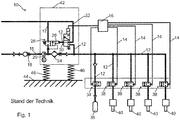
- FIG. 1 schematically shows a compressed air supply device 10 with a bearing device known from the prior art, which consists of three spiral springs 46, of which only two are visible in the illustration.
- the compressed air supply device 10 has an air compressor 20 which comprises a motor-operated air pressure cylinder, preferably a two-stage air pressure cylinder, which is connected to a feed line 11 on the intake side.
- a check valve 18 is provided in the feed line 11, which opens in the suction direction and towards the air compressor 20 and closes in opposite directions by means of spring loading.
- An air dryer 24 is arranged in a pressure line 12 with the pressure side of the air compressor 20.
- a 2/2-way valve 26 is arranged as the first directional valve 26
- a 3/2-way valve 30 as the second way valve 30 via a pressure line 12 with a pneumatic Control input 28 of the first directional valve 26 is connected.
- the pneumatic control input 28 of the first directional valve 26 is connected to the atmosphere by the second directional valve 30 via a connecting line 32.
- each air spring for a wheel 40 of a vehicle is connected to a pressure line 12, in which a 2/2-way valve 38 is arranged as a third directional valve 38, the control input of which is connected to a control device 16 via a control line 14.
- the suspension characteristic of the vehicle wheel can be set via the control line 14.
- a compressed air reservoir 36 is switched on in a pressure line 12, a 2/2-way valve 34 being arranged as a changeover valve 34 at the compressed air inlet of the compressed air reservoir 36.
- a housing 42 comprising the air compressor 20 can be connected to a body 44 of a vehicle.
- the spiral springs 46 are intended to achieve mechanical decoupling of the body, so that vibrations occurring during operation are passed on to the body in a reduced manner. Adjusting the spring characteristics is not possible.
- a compressed air supply device 10 according to a first embodiment of a bearing device 76 according to the invention is shown schematically.
- a housing 42 comprising an air compressor 20 can be connected to a body 44 of a vehicle by the bearing device 76, the bearing device 76 being connected via a pressure line 12 to a 3/2-way valve 50 as a bearing directional valve 50.
- Compressed air can be introduced or removed into the pneumatically operated bearing device 76 via the storage directional control valve 50, so that a spring characteristic of the bearing device 76 can be set depending on the operating state of the air compressor 20.
- the storage directional control valve 50 has a first connection 68 and a second connection 70. Compressed air can be blown out of the bearing device 76 to the atmosphere via an outlet line 66.
- compressed air can be supplied, for example, from the pressure line 12, from the compressed air reservoir 36 and / or from the air spring 40 for a wheel of the air spring 48. While compressed air is supplied to the air spring 48 from at least one of the compressed air sources 12, 36 or 40, the connections of the air spring 48 to the other compressed air sources 12, 36 or 40 can be switched off. For this purpose, for example, further valves can be provided in the system. It is still conceivable to do more Feed compressed air from an additional compressed air reservoir, for example an additional, rechargeable compressed air cartridge (not shown) to the air spring 48.
- the control of the supply of compressed air into the air spring 48 before the activation of the air compressor 20 or the control of the discharge of compressed air after the deactivation of the air compressor 20 can be carried out by a control unit (not shown).
- a motor-operated air pressure cylinder of the air compressor 12 is connected to a feed line 11 on the intake side.
- a check valve 18 is provided in front of the air compressor 20.
- An air dryer 24 is arranged in the pressure line 12 with the pressure side of the air compressor 20. Between the air compressor 20 and the air dryer 24, a 2/2-way valve 26 is provided as the first directional valve 26 in a branch, a 3/2-way valve 30 as the second directional valve 30 via a pressure line 12 to a pneumatic control input 28 of the first directional valve 26 connected.
- the compressed air generated by the compressed air supply device 10 can be fed via a pressure line 12 into four air springs for wheels 40, each air spring 40 being connected to a 2/2-way valve 38, the control input of which is connected to a control device 16 via a control line 14. Furthermore, a compressed air reservoir 36 is provided in a pressure line 12, a 2/2-way valve 34 being arranged as a changeover valve 34 at the compressed air inlet of the compressed air reservoir 36.
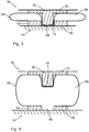
- FIG. 3 and 4 is a side view of the in Fig. 2 bearing device 76 shown in detail accordingly in the idle state ( Fig. 3 ) and in the operating state ( Fig. 4 ) shown.
- the bearing device 76 comprises an upper plate 60 and a lower plate 62 and an air spring 48 with an air bellows 58, the upper plate 60 having a projection 74 and the lower plate 62 having a shape-complementary recess 64.
- An upper part 54 of the bearing device 76 and a lower part 56 of the bearing device 76 can correspondingly be connected to the air compressor 20 and the body 44.
- a decoupling of the air compressor 20 can be achieved by the bearing device 76 both in the idle state and in the operating state.
- the bearing device 76 is in the idle state, in which the upper plate 50 engages in a mechanically positive manner in a damping direction vertically between the body 44 and the air compressor 20 in the lower plate 62. This can result in a horizontal tight fit of the air compressor 20 in the idle state, and in the vertical direction a rigid mounting of the air compressor 20 is brought about by a self-elastic property of the unpressurized air bellows 58.
- Fig. 4 represents the bearing device 76 in the operating state, wherein compressed air can be introduced into the air spring 48 or the air bellows 58 via the recess 64, so that an effective decoupling of the air compressor 20 from the body 44 can be achieved via the air spring 48.
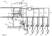
- Fig. 5 schematically shows a compressed air supply device 10 with a second embodiment of a bearing device 76, through which a housing 42 of an air compressor 20 can be connected to a body 44.
- An air compressor 20, an air dryer 24, a 2/2-way valve 26 as a first directional valve 26 and a 3/2-way valve 30 as a second directional valve 30 are arranged in the housing 42, the second directional valve 30 via a pressure line 12 to a pneumatic control input 28 of the first directional valve 26 is connected.
- a check valve 18 is provided in front of the air compressor 20.
- the compressed air generated by the air compressor 20 can be fed into four air springs for wheels 40, wherein a quantity of the compressed air in each air spring for wheel 40 can be controlled by a 2/2-way valve 38 which is designed as a third directional valve 38.
- a control input of the third directional valve 38 is connected to a control device 16 via a control line 14.
- a compressed air reservoir 36 is provided in a pressure line 12, a 2/2-way valve 34 being arranged as a changeover valve 34 at the compressed air inlet of the compressed air reservoir 36.
- a 3/2-way valve serving as a bearing directional valve 50 between the bearing device 76 and the compressed air reservoir 36 is used, which has a first connection 68 and a second connection 70.
- the compressed air can be blown out of the bearing device 76 to the atmosphere via an outlet line 66.
- a vibration sensor 52 is arranged on the housing 42, the vibration sensor 52 being connected to the control device 16, so that vibration signals can be transmitted to the control device 16.
- an air pressure can be set via the bearing directional valve 50 in the bearing device 76 to control the damper characteristic.
- the Fig. 6 illustrates schematically a compressed air supply device 10 with a third embodiment of a bearing device 76.
- An air compressor 20 is arranged in a housing 42.
- An air dryer 24 is provided with the pressure side of the air compressor 20 in a pressure line 12.
- a check valve 17 is arranged in front of the air compressor 20.
- the output side of the air compressor 20 is connected to a 2/2-way valve 26, a second 3/2-way valve 30 being connected to a pneumatic control input 28 of the 2/2-way valve 26.
- the compressed air can be fed via a pressure line 12 into four air springs for wheels 40, whereby a quantity of the compressed air in the air springs for wheels 40 can be changed by a 2/2-way valve 38.
- a control input of the 2/2-way valve 38 is connected to a control device 16 via a control line 14.
- the bearing device 76 is connected to the air compressor 20 via a pressure line 12, so that the compressed air can be provided by the air compressor 20 for the bearing device 76.
- a 3/2-way valve 50 can be used to regulate a variable amount of compressed air in the bearing device 76, which is designed as a bearing directional valve 50.
- a vibration sensor 52 is provided for the bearing device 76.
- the pressure sensor 72 is set up to increase the pressure prevailing in the air bellows 58 determine.
- the vibration sensor 52 is arranged on the housing 42 and the pressure sensor 72 at the compressed air inlet of the bearing device 76 in order to monitor on the one hand a vibration level of the air compressor 20 and on the other hand an air pressure in the bearing device 76.
- an error message can be output with the two sensors if an unexpected vibration occurs.
- the sensor signals of both sensors 52, 72 can be used to improve the position control of the air compressor 20 relative to the body 44.
- the two sensors 52, 72 are connected to the control device 16, so that vibration signals and pressure signals of the control device 16 can be monitored in order to optimize the damping stiffness of the bearing device 76 and to be able to carry out an error monitoring.
Abstract
Die Erfindung betrifft eine Lagervorrichtung (76) für einen Luftkompressor (20) eines Fahrzeugs, durch die der Luftkompressor mit einer Karosserie (44) eines Fahrzeugs schwingungsisolierend verbunden ist.Es wird vorgeschlagen, dass die Lagervorrichtung (76) zumindest eine Luftfeder (48) mit einem elastischen Luftbalg (58) umfasst, wobei die Lagervorrichtung (76) zwischen dem Luftkompressor (20) und der Karosserie (44) angeordnet ist und der Luftbalg (58) an eine Druckluftleitung des Luftkompressors (20) zur Druckluftbefüllung angeschlossen ist.In einem nebengeordneten Aspekt betrifft die Erfindung einen Luftkompressor (20) eines Fahrzeugs, der über eine vorgenannte Lagervorrichtung (76) mit einer Karosserie (44) des Fahrzeugs pneumatisch einstellbar schwingungsisolierend verbunden ist.The invention relates to a bearing device (76) for an air compressor (20) of a vehicle, by means of which the air compressor is connected to a body (44) of a vehicle in a vibration-isolating manner. It is proposed that the bearing device (76) have at least one air spring (48) an elastic air bellows (58), the bearing device (76) being arranged between the air compressor (20) and the body (44) and the air bellows (58) being connected to a compressed air line of the air compressor (20) for filling compressed air The invention relates to an air compressor (20) of a vehicle, which is connected to a body (44) of the vehicle in a pneumatically adjustable, vibration-isolating manner via a bearing device (76).
Description
Die vorliegende Erfindung betrifft eine Lagervorrichtung eines Luftkompressors eines Fahrzeugs, durch die der Luftkompressor mit einer Karosserie des Fahrzeugs schwingungsisolierend verbunden ist.The present invention relates to a bearing device of an air compressor of a vehicle, by means of which the air compressor is connected to a body of the vehicle in a vibration-isolating manner.
Ein Luftkompressor in einem Fahrzeug dient der Bereitstellung von Druckluft für vielfältige pneumatische Aufgaben. Insbesondere in höherwertigen Personenkraftwagen und Lastfahrzeugen werden Radaufhängungen mit pneumatischen Radfedern, die auch als Luftfedern bezeichnet werden, ausgerüstet, um je nach Fahrsituation und gewünschtem Fahrzeugverhalten eine unterschiedliche Federkennlinie einzustellen.An air compressor in a vehicle is used to provide compressed air for a variety of pneumatic tasks. In higher-quality passenger cars and trucks in particular, wheel suspensions are equipped with pneumatic wheel springs, which are also referred to as air springs, in order to set a different spring characteristic depending on the driving situation and the desired vehicle behavior.
In der Regel sind derartige Luftkompressoren an einer Stelle des Fahrzeugs mit der Karosserie verbunden, die Betriebsgeräusche und Vibrationen, die beim Betrieb des Kompressors auftreten, gegenüber der Fahrgastzelle zu minimieren. Dennoch konnte bisher keine vollständige geräuschlose und vibrationsarme Anordnung des Kompressors im Fahrzeug erreicht werden.As a rule, such air compressors are connected to the body at one point of the vehicle in order to minimize the operating noises and vibrations which occur when the compressor is in operation with respect to the passenger compartment. However, it has so far not been possible to achieve a completely silent and low-vibration arrangement of the compressor in the vehicle.
Um dynamische Kraftübertragungen und/oder Schwingungen zu reduzieren, die von einem Luftkompressor im Betrieb erzeugt werden, sind daher Entkopplungsvorrichtungen für den Luftkompressor eines Fahrzeugs notwendig, wobei eine oder mehrere derartige Entkopplungsvorrichtungen zwischen einer Karosserie des Fahrzeugs und dem Luftkompressor angeordnet ist. Die Entkopplungsvorrichtungen haben die Aufgabe, Eigenschwingungen des Luftkompressors derart von einer Karosserie zu isolieren bzw. zu dämpfen, dass eine Körperschallausbreitung des Luftkompressors weitgehend unterdrückt wird. Durch die Entkopplungsvorrichtung werden möglichst wenige dynamische Kräfte, die vom Luftkompressor im Betrieb erzeugt werden, in die Karosserie übertragen. Auf der anderen Seite werden Stöße und Vibrationen der Karosserie vom Luftkompressor isoliert bzw. nur gedämpft an diesen weitergegeben, so dass dieser verringerten äußeren Stoßbelastungen ausgesetzt ist und somit eine höhere Lebensdauer erreichen kann.In order to reduce dynamic force transmissions and / or vibrations that are generated by an air compressor during operation, decoupling devices for the air compressor of a vehicle are therefore necessary, one or more such decoupling devices being arranged between a body of the vehicle and the air compressor. The decoupling devices have the task of isolating or damping natural vibrations of the air compressor from a body in such a way that structure-borne sound propagation of the air compressor is largely suppressed. The decoupling device transfers as few dynamic forces as possible that are generated by the air compressor during operation into the body. On the other hand, shocks and vibrations of the body are isolated from the air compressor or only passed on to it in a dampened manner, so that is exposed to reduced external shock loads and can therefore achieve a longer service life.
Aus dem Stand der Technik sind beispielsweise Lagervorrichtungen mit Spiralfedern als Entkopplungsvorrichtungen bekannt, wobei über die Spiralfedern mit einer geringen Federsteifigkeit ein hoher Entkopplungsgrad des Kompressors zum Fahrzeug erreicht werden kann.For example, bearing devices with spiral springs are known from the prior art as decoupling devices, and a high degree of decoupling of the compressor from the vehicle can be achieved via the spiral springs with a low spring stiffness.
Bei der bekannten Vorrichtung ergibt sich das Problem, dass während der Fahrt der Luftkompressor ständig an Begrenzungselementen stößt oder die Entkopplungs- bzw. Federvorrichtung Stöße und Vibrationen weiterleitet, so dass sich die Arbeitsgeräusche in der Karosserie akustisch bemerkbar machen und somit Lärm generiert wird. Daneben ist es unmöglich, dass unterschiedliche Reduktionseffekte der dynamischen Kraftübertragung insbesondere im Betrieb des Luftkompressors je nach Vibrationsstärke des Luftkompressors erreicht werden, um eine bessere Entkopplung zu ermöglichen. Letztlich kann sich ein unerwünschtes Resonanzverhalten der Entkopplungsvorrichtung bei bestimmten Drehzahlen des Luftkompressors ergeben, die zu einer erhöhten Lärmentwicklung führt.In the known device, the problem arises that the air compressor constantly encounters limiting elements during travel or the decoupling or spring device transmits shocks and vibrations, so that the working noises in the body are acoustically noticeable and noise is thus generated. In addition, it is impossible for different reduction effects of the dynamic power transmission to be achieved, in particular during operation of the air compressor, depending on the vibration level of the air compressor, in order to enable better decoupling. Ultimately, an undesirable resonance behavior of the decoupling device can result at certain speeds of the air compressor, which leads to increased noise.
So ist beispielsweise aus der
Die
Das deutsche Gebrauchsmuster
Die
In der
Weiterhin zeigt die
In der
Die
Die
Weitere gattungsgemäße Vorrichtungen sind in der
Ausgehend von dem obigen Stand der Technik ist es Aufgabe der Erfindung, eine Lagerungsvorrichtung mit einer Luftfeder für einen Luftkompressor eines Fahrzeugs vorzuschlagen, wobei das Volumen der Luftfeder durch Ändern der Druckluftmenge der Luftfeder variierbar ist. Somit werden unterschiedliche Entkopplungseffekte ermöglicht, wobei die Betriebsdruckluft aus dem Luftkompressors selbst entnommen werden kann und eine vereinfachte Federsteuerung erreicht werden kann.Starting from the above prior art, it is an object of the invention to propose a mounting device with an air spring for an air compressor of a vehicle, the volume of the air spring being variable by changing the amount of compressed air in the air spring. Different decoupling effects are thus made possible, the operating compressed air being able to be taken from the air compressor itself and simplified spring control being achieved.
Diese Aufgabe wird durch eine Lagervorrichtung für einen Luftkompressor eines Fahrzeugs nach dem unabhängigen Anspruch gelöst. Vorteilhafte Weiterbildungen der Erfindung sind Gegenstand der Unteransprüche.This object is achieved by a bearing device for an air compressor of a vehicle according to the independent claim. Advantageous developments of the invention are the subject of the dependent claims.
Es wird eine Lagervorrichtung für einen Luftkompressor mit einer Karosserie eines Fahrzeugs vorgeschlagen, durch die der Luftkompressor mit einer Karosserie eines Fahrzeugs schwingungsisolierend verbunden ist.A bearing device for an air compressor with a body of a vehicle is proposed, by means of which the air compressor is connected to a body of a vehicle in a vibration-isolating manner.
Erfindungsgemäß wird vorgeschlagen, dass die Lagervorrichtung zumindest eine Luftfeder mit einem elastischen Luftbalg umfasst, wobei der Luftbalg an eine Druckluftleitung des Luftkompressors zu steuerbaren Druckluftbefüllung angeschlossen ist.It is proposed according to the invention that the bearing device comprises at least one air spring with an elastic air bellows, the air bellows being connected to a compressed air line of the air compressor for controllable compressed air filling.
Mit anderen Worten wird eine einen elastischen Luftbalg aufweisende Luftfeder vorgeschlagen, wobei der Luftbalg vorzugsweise aus Gummi oder einem formschlaffen, flexiblen Material vorgeschlagen wird, wobei die Steifigkeit der Lagervorrichtung durch die Elastizität und das eingeführte Luftdruckvolumen des Luftbalgs geändert werden kann. Schwingungsisolierende Eigenschaft bedeutet, dass der Luftbalg im drucklosen Zustand eine höhere Steifigkeit besitzt, und somit eine geringere Schwingungsisolation aufweist.In other words, an air spring having an elastic air bellows is proposed, the air bellows preferably being made of rubber or a flexible, flexible material, wherein the rigidity of the bearing device can be changed by the elasticity and the introduced air pressure volume of the air bellows. Vibration-isolating property means that the air bellows has a higher rigidity when unpressurized and therefore has less vibration isolation.
Erfindungsgemäß wird vorteilhaft erreicht, dass die aus zumindest einer Luftfeder bestehende Lagervorrichtung zur Entkopplung des Luftkompressors von der Karosserie vorgesehen ist. Die Lagervorrichtung ist dabei zwischen dem Luftkompressor und der Karosserie angeordnet. Im Betrieb des Luftkompressors wird kein Lärm aufgrund von Stößen zwischen dem Luftkompressor und den Spiralfedern umschließenden Begrenzungselementen generiert. Daneben ist durch Einsatz der Lagervorrichtung, die auf der einen Seite mit dem Luftkompressor und auf der anderen Seite mit der Karosserie verbunden ist, die Übertragung von dynamischen Kräften in die Karosserie reduzierbar und somit kann eine bessere Entkopplung erreicht werden.According to the invention it is advantageously achieved that the bearing device consisting of at least one air spring is provided for decoupling the air compressor from the body. The bearing device is arranged between the air compressor and the body. During operation of the air compressor, no noise is generated due to impacts between the air compressor and the limiting elements surrounding the coil springs. In addition, the use of the bearing device, which is connected on one side to the air compressor and on the other side to the body, can reduce the transmission of dynamic forces into the body and thus better decoupling can be achieved.
Weiterhin weist der Luftbalg einen Anschluss zum Verbinden mit einer Druckluftleitung eines gelagerten Luftkompressors auf, der vorzugsweise Druckluft für eine Fahrzeugfederung bereitstellt. Somit kann der Luftbalg im Betrieb des Luftkompressors über die Druckluftleitung mit Druckluft gefüllt und aufgeblasen werden. Hierzu kann beispielsweise über eine Steuereinrichtung wie zum Beispiel eine Elektronikeinheit ein in der Druckluftleitung enthaltenes Ventil angesteuert werden, wobei beim Aufblasen das Ventil in Öffnungsstellung angesteuert wird. Auch kann ungesteuert ein Aufblasen im Betrieb und ein druckloser Zustand im Ruhezustand des Luftkompressors eine relativ einfache adaptive Lagerung ermöglichen.Furthermore, the air bellows has a connection for connecting to a compressed air line of a mounted air compressor, which preferably provides compressed air for a vehicle suspension. The air bellows can thus be filled and inflated with compressed air via the compressed air line during operation of the air compressor. For this purpose, for example, a valve contained in the compressed air line can be controlled via a control device such as an electronic unit, the valve being controlled in the open position when inflated. Uncontrolled inflation during operation and a depressurized state in the idle state of the air compressor can enable relatively simple adaptive storage.
Alternativ denkbar ist, dass der Luftbalg über eine Druckluftleitung an einen Druckluftspeicher eines Fahrzeugabfederungssystems angeschlossen ist. Über eine andere Druckleitung wird die vom Luftkompressor erzeugte überschüssige Druckluft in den Druckluftspeicher eingebracht, so dass der Druckluftspeicher aufgeblasen werden kann. Um Schwingungen zu isolieren, kann der Luftbalg an den Druckluftspeicher angeschlossen und somit die Druckluft in den Luftbalg geleitet werden. Zum Ansteuern eines Aufblasprozesses kann ein Ventil in der mit dem Luftbalg verbundenen Druckluftleitung vorhanden sein, wobei das Ventil von der Steuereinrichtung kontrolliert werden kann. Je nach Bedarf ist das Ventil zwischen einer Öffnungsstellung und einer Schließstellung verstellbar. Hierdurch kann der Luftbalg steuerbar aufgeblasen und ausgeblasen werden.Alternatively, it is conceivable that the air bellows is connected to a compressed air accumulator of a vehicle suspension system via a compressed air line. The excess compressed air generated by the air compressor is introduced into the compressed air reservoir via another pressure line, so that the compressed air reservoir can be inflated. In order to isolate vibrations, the air bellows can be connected to the compressed air reservoir and thus the compressed air can be directed into the air bellows. To control an inflation process, a valve can be present in the compressed air line connected to the air bellows, the valve being able to be controlled by the control device. The valve can be adjusted between an open position and a closed position as required. As a result, the air bellows can be inflated and blown out in a controllable manner.
Es ist vorteilhaft, dass die Lagervorrichtung mehrere Luftfedern, insbesondere drei und mehr umfassen kann, wobei jede Luftfeder je einen elastischen Luftbalg aufweist. Insbesondere ist der Luftkompressor ausschließlich durch Luftfedern mit der Karosserie verbunden. Für verschiedene Luftkompressoren können unterschiedliche Typen von Lagevorrichtungen mit einer unterschiedlichen Anzahl von Luftfedern zur Reduktion der Kraftübertragung bei Schwingung bzw. Vibration des Luftkompressors eingesetzt werden.It is advantageous that the bearing device can comprise a plurality of air springs, in particular three or more, each air spring each having an elastic air bellows. In particular, the air compressor is connected to the body exclusively by air springs. Different types of position devices with a different number of air springs can be used for different air compressors to reduce the transmission of force when the air compressor vibrates.
In einer vorteilhaften Weiterbildung kann die Luftfeder zumindest zweistufig ausgebildet sein, und vorzugsweise eine obere Platte und eine untere Platte umfassen, wobei die obere Platte und die untere Platte jeweils entsprechend an einem Oberteil und Unterteil des Luftbalgs angeordnet ist. Die obere Platte und die untere Platte können aus einem formstabilen, harten Material, beispielsweise aus Metall oder Plastik hergestellt werden, und jeweils entsprechend an einer oberen Stirnfläche und einer unteren Stirnfläche des Luftbalgs mit verschiedenen Verbindungsmöglichkeiten wie zum Beispiel durch Ankleben befestigt sein kann. Ist das am Luftbalg angeordnete Ventil ausgeschaltet, kann der Luftkompressor aus einem elastischen Sitz gehoben werden, der aus dem elastischen Luftbalg gebildet ist. Ist das Ventil eingeschaltet, kann der Luftbalg mit der Druckluft vollständig gefüllt werden, so dass der Luftkompressor über die gebildete Luftfeder von der Karosserie entkoppelt sein kann. Im drucklosen Zustand weist der Luftbalg vorteilhaft eine selbstrückstellende Ausgangsform auf, in der die beiden Platten sich gegenüberliegen, und das dazwischenliegende Luftbalgmaterial eine verringerte Entkopplungseigenschaft bereitstellt.In an advantageous further development, the air spring can be formed at least in two stages and preferably comprise an upper plate and a lower plate, the upper plate and the lower plate being respectively arranged on an upper part and lower part of the air bellows. The upper plate and the lower plate can be made of a dimensionally stable, hard material, for example made of metal or plastic, and can in each case be fastened to an upper end face and a lower end face of the air bellows with different connection options, for example by gluing. If the valve arranged on the air bellows is switched off, the air compressor can be lifted out of an elastic seat which is formed from the elastic air bellows. If the valve is switched on, the air bellows can be completely filled with the compressed air, so that the air compressor can be decoupled from the body via the air spring formed. In the depressurized state, the air bellows advantageously has a self-resetting initial shape in which the two plates lie opposite one another and the air bellows material in between provides a reduced decoupling property.
In einer weiteren vorteilhaften Weiterbildung kann sich die zweistufige Luftfeder im Ruhezustand in einer mechanisch festgelegten Ausgangsstellung befinden. Mit anderen Worten kann eine derart Stellung der zweistufigen Luftfeder als die Ausgangsstellung ausgebildet sein, wenn keine Luft im Luftbalg vorhanden ist. In diesem Fall kann die Lagerung des Luftkompressors über das elastische Material des Luftbalgs erfolgen, wobei ein mechanischer Festsitz - zumindest in einer Vorzugsrichtung vertikal zwischen Karosserie und Luftkompressor - zwischen dem Oberteil und dem Unterteil des Luftbalgs erreicht werden kann.In a further advantageous development, the two-stage air spring can be in a mechanically defined starting position in the idle state. In other words, such a position of the two-stage air spring can be designed as the starting position if there is no air in the air bellows. In this case, the air compressor can be mounted on the elastic material of the air bellows, whereby a mechanical tight fit - at least in a preferred direction vertically between the body and the air compressor - can be achieved between the upper part and the lower part of the air bellows.
In einer weiteren vorteilhaften Weiterbildung kann in der Ausgangsstellung die obere Platte - bedingt durch eine selbstrückstellende Federwirkung des Luftbalgmaterials - mechanisch formschlüssig in die untere Platte eingreifen, sobald der Luftbalg drucklos ist, so dass in horizontaler Richtung zwischen dem Luftkompressor und der Karosserie eine Bewegung des Luftkompressors mechanisch festgelegt ist und in vertikaler Richtung als Vorzugsrichtung vom Luftkompressor zur Karosserie eine Federspannung von dem Luftbalgwandung ausgeübt wird. In dieser Weiterbildung kann eine Druckluftleitung zum Verbinden des Luftbalgs mit der Atmosphäre über das Ventil vorgesehen sein, wobei die Druckluftleitung einseitig, d. h auf der einen Seite, mit dem Anschluss des Luftbalgs verbunden sein und der Luftbalg anderseitig, d. h auf der anderen Seite, über diese Druckluftleitung zur Atmosphäre entlüftet werden kann. Dadurch, dass die obere und untere Platte ineinander eingreifen und sich zeitgleich das Ventil in Schließstellung befindet, kann der drucklose Luftbalg bereitgestellt sein. Hierdurch kann sich ein horizontaler Festsitz des Luftbalgs ergeben, so dass im Ruhezustand die Lagerung des Luftkompressors in horizontaler Richtung zwischen dem Luftkompressor und der Karosserie fest ist und relativ steif gelagert ist. Dagegen ist eine Federspannung vom Material des Luftbalgs in vertikaler Richtung vom Luftkompressor zur Karosserie bereitgestellt. Mit der Federspannung kann der Luftkompressor von der Karosserie im Ruhezustand hinreichend entkoppelt gelagert werden.In a further advantageous development, in the starting position, the upper plate - due to a self-resetting spring action of the air bellows material - can engage mechanically in a form-fitting manner in the lower plate as soon as the air bellows is depressurized, so that the air compressor moves in a horizontal direction between the air compressor and the body is mechanically fixed and a spring tension is exerted by the air bellows wall in the vertical direction as the preferred direction from the air compressor to the body. In this development, a compressed air line can be provided for connecting the air bellows to the atmosphere via the valve, the compressed air line on one side, ie. h on one side, be connected to the connection of the air bellows and the air bellows on the other side, d. h on the other hand, can be vented to the atmosphere via this compressed air line. Because the upper and lower plates engage in one another and the valve is in the closed position at the same time, the pressureless air bellows can be provided. This can result in a horizontal tight fit of the air bellows, so that in the idle state the bearing of the air compressor is fixed in the horizontal direction between the air compressor and the body and is mounted relatively stiffly. In contrast, a spring tension from the material of the air bellows is provided in the vertical direction from the air compressor to the body. With the spring tension, the air compressor can be stored sufficiently decoupled from the body in the idle state.
In einer weiteren vorteilhaften Weiterbildung kann die untere Platte zumindest eine Ausnehmung und die obere Platte zumindest einen formkomplementären Vorsprung aufweisen, wobei bevorzugt der Vorsprung und die Ausnehmung im Zentralbereich der entsprechenden Platte ausgeformt sind. Die obere und die untere Platte dienen zur Befestigung des Luftkompressors an der Karosserie. Im Randbereich beider Platten können hierzu wie zum Beispiel Befestigungslöcher vorgesehen sein, durch die Schrauben oder Nieten zur Befestigung der oberen Platte und unteren Platte entsprechend an dem Luftkompressor und der Karosserie geführt werden können. Vorteilhafterweise kann der Vorsprung formkomplementär zum Innenprofil der Ausnehmung ausgebildet sein, so dass die obere Platte in die untere Platte mechanisch festgelegt eingesteckt werden kann. Beim Einstecken kann der Innenoberflächenabschnitt des Luftbalgs bezüglich des Vorsprungs der oberen Platte den innenoberflächenabschnitt des Luftbalgs bezüglich der Ausnehmung der unteren Platte kontaktieren. Hierdurch kann sich die Luftfeder in einer mechanisch festgelegten Ausgangsstellung befinden.In a further advantageous development, the lower plate can have at least one recess and the upper plate has at least one complementary projection, the projection and the recess preferably being formed in the central region of the corresponding plate. The top and bottom plates are used to attach the air compressor to the body. For this purpose, fastening holes can be provided in the edge region of both plates, for example, through which screws or rivets for fastening the upper plate and lower plate can be guided accordingly on the air compressor and the body. Advantageously, the projection can be complementary to the inner profile of the recess, so that the upper plate can be inserted into the lower plate in a mechanically fixed manner. When inserted, the inner surface portion of the air bladder with respect to the protrusion of the upper plate can contact the inner surface portion of the air bladder with respect to the recess of the lower plate. As a result, the air spring can be in a mechanically fixed starting position.
In einer weiteren vorteilhaften Weiterbildung kann im Betriebszustand durch eine Druckbeaufschlagung des Luftbalgs eine federnde Lagerung sowohl in horizontaler Richtung als auch in vertikaler Richtung gebildet sein. Im Betrieb des Luftkompressors kann das Ventil von der Steuereinrichtung gesteuert werden und sich in Öffnungsstellung befinden, so dass die vom Luftkompressor verdichtete Druckluft durch die Druckluftleitung zum Luftbalg geführt werden kann. Je mehr Druckluft im Luftbalg ist, desto größere Federspannung kann von der Luftfeder bereitgestellt sein. Vorteilhafterweise kann durch eine vollständige Füllung des Luftbalgs eine weiche Lagerung erreicht werden, die sowohl in horizontaler Richtung als auch in vertikaler Richtung gebildet ist, so dass unerwünschte Vibrationen oder Körperschall durch Betrieb des Luftkompressors optimal reduziert werden können. Eine Erhöhung des Luftdrucks kann zu einer Erhöhung der Federsteifigkeit und ein Absenken des Luftdrucks zu einer Verringerung der Federsteifigkeit führen, so dass auf Basis des Luftdrucks unterschiedliche Steifigkeitswerte erreicht werden können.In a further advantageous development, a resilient mounting can be formed both in the horizontal direction and in the vertical direction in the operating state by pressurizing the air bellows. When the air compressor is operating, the valve can be controlled by the control device and be in the open position, so that the compressed air compressed by the air compressor can be guided through the compressed air line to the air bellows. The more compressed air there is in the air bellows, the greater the spring tension that can be provided by the air spring. Advantageously, a complete storage of the air bellows enables a soft bearing to be achieved, which is formed both in the horizontal direction and in the vertical direction, so that undesired vibrations or structure-borne noise can be optimally reduced by operating the air compressor. An increase in the air pressure can lead to an increase in the spring stiffness and a decrease in the air pressure to a decrease in the spring stiffness, so that different stiffness values can be achieved on the basis of the air pressure.
In einer weiteren vorteilhaften Ausführungsform kann ein steuerbares Lagerungswegeventil mit der zweistufigen Luftfeder verbunden sein. Vorteilhafterweise kann ein 3/2-Wegeventil als Lagerungswegeventil angeordnet sein, so dass das Lagerungswegeventil auf verschiedene Schaltungsstellung zur Druckbeaufschlagung, Druckentleerung und Druckverriegelung umgeschaltet werden kann. Das Lagerungswegeventil kann über eine Anschlussleitung an dem Luftbalg angeordnet sein, wobei die Druckluft entweder von dem Luftkompressor oder von dem Druckluftspeicher über die Druckleitung bereitgestellt werden kann. Hierdurch ist eine stufenlose Regelung der Steifigkeit gegeben.In a further advantageous embodiment, a controllable bearing directional control valve can be connected to the two-stage air spring. Advantageously, a 3/2-way valve can be arranged as a storage directional control valve, so that the storage directional control valve can be switched to different switching positions for pressurization, pressure relief and pressure locking. The storage directional control valve can be arranged on the air bellows via a connecting line, the compressed air being able to be provided either by the air compressor or by the compressed air reservoir via the pressure line. This provides a stepless regulation of the rigidity.
In einer vorteilhaften Ausführungsform kann das steuerbare Lagerungswegeventil zeitlich vorgelagert eine Aktivierung der Luftfeder vor Aktivierung des Luftkompressors erzielen. Dadurch kann eine zeitliche Hysterese gebildet werden, wobei die Aktivierung des Luftlagers bzw. die Aktivierung des Luftkompressors zeitlich vor Einschalten und ein Ablassen der Luftfeder nach Abschalten des Luftkompressors erreicht werden, um auch An- und Ablaufgeräusche des Luftkompressors zu unterdrücken. Somit kann bereits vor dem Start des Luftkompressors eine Luftlagerung des Luftkompressors erfolgen. Eine Unterdrückung von Arbeitsgeräuschen kann so besonders vorteilhaft sichergestellt werden, da auch unterschiedliche Arten von Anfahrgeräuschen des Luftkompressors kompensiert werden können.In an advantageous embodiment, the controllable bearing directional control valve can activate the air spring before activating the air compressor. A hysteresis over time can thereby be formed, wherein the activation of the air bearing or the activation of the air compressor can be achieved before switching on and a deflation of the air spring after switching off the air compressor in order to suppress start-up and discharge noises of the air compressor. This means that the air compressor can be stored in air before the air compressor starts. Suppression of working noises can be ensured in a particularly advantageous manner since different types of starting noises of the air compressor can also be compensated for.
In einer vorteilhaften Ausführungsform kann eine Steuereinheit eingerichtet sein, zeitlich vor Aktivierung des Luftkompressors aus einem Druckluftreservoir Druckluft zur Aktivierung der Luftfeder zu ziehen und das steuerbare Lagerungswegeventil zeitlich vorgelagert und/oder zeitlich nachgelagert zu betätigen, insbesondere zeitlich nachgelagert die Luftfeder wieder abzulassen. Auch dadurch kann bereits vor dem Start des Luftkompressors durch das Druckluftreservoir die Luftlagerung des Luftkompressors aktiviert werden. Das Druckluftreservoir kann beispielsweise ein zusätzlicher Drucklufttank oder auch ein bereits im System vorhandener Drucklufttank sein. Durch die zeitlich vorgelagerte Aktivierung und / oder zeitlich nachgelagerte Deaktivierung des Lagerungswegeventils kann besonders vorteilhaft eine akustische Entkopplung zur Karosserie und Unterdrückung von Arbeitsgeräuschen des Luftkompressors erfolgen. Durch eine zeitlich nachgelagerte Deaktivierung des Lagerungswegeventils kann die Luftfedern beim Ausschalten des Luftkompressors verzögert in Ruhestellung gelangen, wodurch beispielsweise Abfahrgeräusche des Luftkompressors kompensiert werden können.In an advantageous embodiment, a control unit can be set up to draw compressed air from a compressed air reservoir for activating the air spring before activation of the air compressor and to actuate the controllable storage directional control valve upstream and / or afterwards, in particular to release the air spring afterwards. This also enables the air storage of the air compressor to be activated by the compressed air reservoir before the air compressor starts. The compressed air reservoir can, for example, be an additional compressed air tank or an already existing compressed air tank. By activating and / or deactivating the storage directional control valve in advance, acoustic decoupling from the body and suppression of working noises of the air compressor can take place particularly advantageously. By deactivating the storage directional control valve at a later time, the air springs can come to a rest position with a delay when the air compressor is switched off, as a result of which, for example, the noise from the air compressor can be compensated.
In einer vorteilhaften Ausführungsform kann durch das steuerbare Lagerungswegeventil Druckluft aus einem Druckluftreservoir, insbesondere aus einer Druckluftleitung des Fahrzeugs, aus einer Luftfeder für ein Rad, aus einem Druckluftverbindungssystem des Fahrzeugs, aus einem Druckluftspeicher und/oder aus einem Zusatz-Druckluftspeicher, der Luftfeder zugeführt werden. Die Druckluft kann folglich aus unterschiedlichen Luftquellen bezogen werden. Bevorzugt können zu dem Zeitpunkt, zu welchem der Luftfeder wie oben beschrieben Druckluft zugeführt wird, die Druckluftzuführungen zum Luftkompressor abgeschaltet bzw. blockiert sein. Dafür können weitere Ventile vorgesehen sein.In an advantageous embodiment, compressed air from a compressed air reservoir, in particular from a compressed air line of the vehicle, from an air spring for a wheel, from a compressed air connection system of the vehicle, from a compressed air reservoir and / or from an additional compressed air reservoir, can be supplied to the air spring by the controllable bearing directional control valve . The compressed air can therefore be obtained from different air sources. The compressed air feeds to the air compressor can preferably be switched off or blocked at the time at which compressed air is supplied to the air spring as described above. Additional valves can be provided for this.
Beispielsweise kann die Luftfeder 1-10 Sekunden, insbesondere 2-5 Sekunden, vor der Aktivierung des Luftkompressors mit Druckluft befüllt bzw. nach Abschaltung des Luftkompressors drucklos geschaltet werden. Die eben beschriebenen Zeiträume können ebenso unter 1 Sekunde liegen.For example, the air spring can be filled with compressed air for 1-10 seconds, in particular 2-5 seconds, before the air compressor is activated, or depressurized after the air compressor has been switched off. The periods just described can also be less than 1 second.
In einer weiteren vorteilhaften Weiterbildung kann das Lagerungswegeventil elektrisch steuerbar sein. Das Lagerungswegeventil wird auch als elektrisch betätigtes Ventil bezeichnet. Das Lagerungswegeventil kann an einen elektrischen Anschluss der Steuereinrichtung angeschlossen sein. Mittels einer elektrischen Spannung, die von der Steuereinrichtung ausgegeben wird, kann das Lagerungswegeventil derart betätigt werden, dass ein Elektromagnet als Betätigungselement mit der elektrischen Spannung angesteuert und somit das Umschalten des Ventils eingeleitet werden kann. Es ist vorteilhaft, dass das Lagerungswegeventil elektrisch ansteuerbar ist und keine komplizierte mechanische Verbindung oder umfangreiche pneumatische Vorsteuerungen vorgesehen sind, um das Lagerungswegeventil zu betätigen. Des Weiteren kann der Einsatz eines elektrisch betätigten Ventils zu einer deutlich einfacheren Installation bei geringeren Kosten führen.In a further advantageous development, the bearing directional control valve can be electrically controllable. The bearing directional control valve is also referred to as an electrically operated valve. The storage directional control valve can be connected to an electrical connection of the control device. By means of an electrical voltage that is output by the control device, the bearing directional control valve can be actuated in such a way that an electromagnet as an actuating element can be actuated with the electrical voltage and the switching of the valve can thus be initiated. It is advantageous that the storage directional control valve can be controlled electrically and no complicated mechanical connection or extensive pneumatic pilot controls are provided to actuate the storage directional control valve. Furthermore, the use of an electrically operated valve can lead to a significantly easier installation at lower costs.
In einer weiteren vorteilhaften Weiterbildung kann das Lagerungswegeventil pneumatisch steuerbar sein. Das Lagerungsventil wird als Pneumatikventil bezeichnet. Im Vergleich zur vorigen Weiterbildung ist anstelle eines elektrischen Anschlusses ein Anschluss für die Druckluft vorgesehen, wobei das Lagerungswegeventil mittels einer Steuerdruckluft des Luftdrucksystems umgeschaltet werden kann. Mit einem Pneumatikventil wird ein niedriger Kostenaufwand ermöglicht, und es kann auf zusätzliche, ausfallgefährdete elektrische Komponenten verzichtet werden.In a further advantageous development, the bearing directional control valve can be controlled pneumatically. The storage valve is called a pneumatic valve. In comparison to the previous development, a connection for the compressed air is provided instead of an electrical connection, and the bearing directional control valve can be switched by means of a control compressed air of the air pressure system. A pneumatic valve enables a low cost and there is no need for additional electrical components that are at risk of failure.
In einer weiteren vorteilhaften Weiterbildung kann das Lagerungswegeventil zwei Anschlüsse aufweisen, wobei ein erster Anschluss mit dem Druckluftausgang des Luftkompressors oder mit einem Druckluftausgang eines Druckluftspeichers verbunden ist, wobei ein zweiter Anschluss über eine Ausgangsleitung mit der Atmosphäre verbunden ist. Hierzu sind eine erste Schaltstellung und eine zweite Schaltstellung vorgesehen. Wird das Lagerungsventil auf die erste Schaltstellung umgeschaltet, kann der Luftbalg mit der unmittelbar vom Luftkompressor erzeugten Druckluft oder der im Druckluftspeicher erhaltenen Druckluft je nach der Verbindung gefüllt werden, so dass sich die Luftfeder im Betriebszustand befinden kann. Wird das Lagerungsventil auf die zweite Schaltstellung umgeschaltet, kann die Druckluft im Luftbalg über die Ausgangsleitung zur Atmosphäre ausgeblasen werden, so dass sich die Luftfeder in den Ruhezustand befinden kann. Hierdurch wird eine einfache Drucksteuerung einer einstellbaren Federsteifigkeit ermöglicht.In a further advantageous development, the storage directional control valve can have two connections, a first connection being connected to the compressed air outlet of the air compressor or to a compressed air outlet of a compressed air store, a second connection being connected to the atmosphere via an outlet line. For this purpose, a first switching position and a second switching position are provided. If the storage valve is switched to the first switching position, the air bellows can be filled with the compressed air generated directly by the air compressor or the compressed air received in the compressed air reservoir depending on the connection, so that the air spring can be in the operating state. If the storage valve is switched to the second switching position, the compressed air in the air bellows can be blown out to the atmosphere via the outlet line, so that the air spring can be in the idle state. This enables simple pressure control of an adjustable spring stiffness.
In einer weiteren vorteilhaften Ausführungsform kann ein Vibrationssensor an dem Kompressor zur Überwachung von Vibration des Luftkompressors angeordnet sein, wobei eine variierbare Menge der in den Luftbalg geleiteten Druckluft gemäß der Vibrationsstärke des Luftkompressors über das Lagerungswegeventil regulierbar ist. Der Vibrationssensor kann an einen elektrischen Anschluss der Steuereinrichtung angeschlossen sein, wobei der Vibrationssensor die Vibrationsstärke des Luftkompressors erfassen und ein darauf ansprechendes Vibrationssignal erzeugen kann. Das Vibrationssignal wird der Steuereinrichtung übersendet und somit steuert die Steuereinrichtung das Lagerungswegeventil an, um das Lagerungswegeventil auf eine Öffnungsstellung oder eine Schließstellung umzuschalten. Vorteilhafterweise ist die Menge der Druckluft im Luftbalg gemäß der Vibrationsstärke des Luftkompressors änderbar, und ggf. über eine Kennlinie mit dieser korreliert. Mit dem Vibrationssensor können eine adaptive Federungseigenschaft der Lagervorrichtung, insbesondere eine oder mehrere angepasste Luftfedern für verschiedene Vibrationsstärke des Luftkompressors bereitgestellt sein, so dass eine verbesserte Entkopplung des Luftkompressors ermöglicht wird.In a further advantageous embodiment, a vibration sensor can be arranged on the compressor for monitoring the vibration of the air compressor, wherein a variable amount of the compressed air guided into the air bellows can be regulated via the bearing directional control valve according to the vibration intensity of the air compressor. The vibration sensor can be connected to an electrical connection of the control device, wherein the vibration sensor can detect the vibration intensity of the air compressor and can generate a vibration signal responsive to it. The vibration signal is sent to the control device and thus the control device controls the storage directional control valve in order to switch the storage directional control valve to an open position or a closed position. Advantageously, the amount of compressed air in the air bellows can be changed according to the vibration level of the air compressor and, if necessary, correlated with it via a characteristic curve. The vibration sensor can be used to provide an adaptive suspension property of the bearing device, in particular one or more adapted air springs for different vibration levels of the air compressor, so that an improved decoupling of the air compressor is made possible.
Anschließend an das vorherige Ausführungsbeispiel kann in einer weiteren vorteilhaften Weiterbildung bei hoher Vibrationsstärke des Luftkompressors eine dafür angepasste Druckluft in den Luftbalg einbringbar sein. Dies muss nicht unbedingt eine maximale Druckluftstärke sein, sondern kann z.B. kennlinienbasiert eine Druckluftmenge sein, die eine optimale Federsteifigkeit zur Entkopplung bereitstellt. Hierdurch kann eine optimale Entkopplung des Luftkompressors erreicht werden.Following the previous exemplary embodiment, in a further advantageous development with a high vibration level of the air compressor, compressed air adapted for this can be introduced into the air bellows. This does not necessarily have to be a maximum compressed air strength, but can e.g. based on the characteristic curve, a quantity of compressed air that provides optimum spring stiffness for decoupling. In this way, an optimal decoupling of the air compressor can be achieved.
In einer weiteren vorteilhaften Ausführungsform kann ein Drucksensor zum Erfassen des Luftdrucks im Luftbalg und zum Erzeugen eines Darauf ansprechenden Drucksignals umfasst sein, wobei der Drucksensor am Eingang des Luftbalgs angeordnet ist. Der Drucksensor kann im Anschlusskanal zwischen der Luftfeder und dem Lagerungswegeventil angeordnet sein, um der Luftdruck an einem Drucklufteingang bzw. Druckluftausgang des Luftbalgs zu erfassen. Der Drucksensor kann sein Signal an einen Anschluss der Steuereinrichtung weitergeben, so dass das Drucksignal der Steuereinrichtung übersendet wird und hiermit das Lagerungswegeventil von der Steuereinrichtung adaptiv angesteuert werden kann.In a further advantageous embodiment, a pressure sensor for detecting the air pressure in the air bellows and for generating a pressure signal responsive thereto can be included, the pressure sensor being arranged at the inlet of the air bellows. The pressure sensor can be arranged in the connection channel between the air spring and the bearing directional control valve in order to detect the air pressure at a compressed air inlet or compressed air outlet of the air bellows. The pressure sensor can pass on its signal to a connection of the control device, so that the pressure signal is transmitted to the control device and the storage directional control valve can hereby be controlled adaptively by the control device.
Vorteilhafterweise sind ein Drucksensor am Drucklufteingang des Luftbalgs und ein Vibrationssensor am Luftkompressor angeordnet. Mit den beiden Sensoren kann eine Fehlermeldung ausgegeben werden, wobei selbst bei angepasstem Luftdruck im Luftbalg, z.B. zur Resonanzunterdrückung, der Luftkompressor unerwartet stark vibriert. Das heißt, wenn eine unerwartete Vibration auftritt, kann ein Fehlerfall durch die beiden Sensoren in Kombination festgestellt werden.A pressure sensor is advantageously arranged on the compressed air inlet of the air bellows and a vibration sensor on the air compressor. An error message can be output with the two sensors, whereby even with adjusted air pressure in the air bellows, e.g. to suppress resonance, the air compressor vibrates unexpectedly strongly. This means that if an unexpected vibration occurs, an error can be determined by the two sensors in combination.
Anschließend an das vorherige Ausführungsbeispiel kann in einer weiteren vorteilhaften Weiterbildung durch Messen des Luftdrucks im Luftbalg eine Menge der Druckluft in den Luftbalg über das Lagerungswegeventil steuerbar geändert sein. Der Drucksensor kann in Echtzeit den Luftdruck im Luftbalg erfassen, hiermit ist die Menge der Druckluft entsprechend der Druckstärke über das Lagerungswegeventil änderbar, das von der Steuereinrichtung gesteuert werden kann. Somit kann der Luftkompressor im Betrieb optimiert entkoppelt werden.Following the previous exemplary embodiment, in a further advantageous development, by measuring the air pressure in the air bellows, a quantity of the compressed air in the air bellows can be changed in a controllable manner via the storage directional valve. The pressure sensor can detect the air pressure in the air bellows in real time; the amount of compressed air can hereby be changed according to the pressure strength via the bearing directional control valve, which can be controlled by the control device. The air compressor can thus be optimally decoupled during operation.
In einem nebengeordneten Aspekt wird ein Luftkompressor eines Fahrzeugs vorgeschlagen, der über eine vorbeschriebene Lagervorrichtung mit einer Karosserie eines Fahrzeugs schwingungsisolierend verbunden ist. Der erfindungsgemäße Luftkompressor umfasst eine Lagervorrichtung nach einem der vorgenannten Ausführungsbeispiele. Eine derartige Lagervorrichtung ist auch als Ersatzteil zum Austausch oder zur Weiterbildung bereits vorhandenes Luftkompressors vorteilhaft einsetzbar.In a secondary aspect, an air compressor of a vehicle is proposed, which is connected to a body of a vehicle in a vibration-isolating manner by means of a bearing device as described above. The air compressor according to the invention comprises a bearing device according to one of the aforementioned exemplary embodiments. Such a bearing device can also be used advantageously as a spare part for replacing or further developing an air compressor.
Weitere Vorteile ergeben sich aus den vorliegenden Zeichnungsbeschreibungen. In den Zeichnungen sind Ausführungsbeispiele der Erfindung dargestellt. Die Zeichnungen, die Beschreibung und die Ansprüche enthalten zahlreiche Merkmale in Kombination. Der Fachmann wird die Merkmale zweckmäßigerweise auch einzeln betrachten und zu sinnvollen weiteren Kombinationen zusammenfassen.Further advantages result from the present description of the drawings. Exemplary embodiments of the invention are shown in the drawings. The drawings, description, and claims contain numerous features in combination. The person skilled in the art will expediently also consider the features individually and combine them into useful further combinations.
Es zeigen:
- Fig. 1
- eine schematische Darstellung einer Druckluftversorgungsvorrichtung mit einer Lagervorrichtung gemäß dem Stand der Technik;
- Fig. 2
- eine schematische Darstellung einer Druckluftversorgungsvorrichtung mit einer ersten Ausführungsform einer Lagervorrichtung gemäß der Erfindung;
- Fig. 3
- Seitenansicht der in
Fig. 2 im Ruhezustand dargestellten Lagervorrichtung; - Fig. 4
- Seitenansicht der in
Fig. 2 im Betriebszustand dargestellten Lagervorrichtung; - Fig. 5
- eine schematische Darstellung einer Druckluftversorgungsvorrichtung mit einer zweiten Ausführungsform einer Lagervorrichtung der Erfindung;
- Fig. 6
- eine schematische Darstellung einer Druckluftversorgungsvorrichtung mit einer dritten Ausführungsform einer Lagervorrichtung der Erfindung.
- Fig. 1
- is a schematic representation of a compressed air supply device with a storage device according to the prior art;
- Fig. 2
- is a schematic representation of a compressed air supply device with a first embodiment of a storage device according to the invention;
- Fig. 3
- Side view of the in
Fig. 2 bearing device shown in the idle state; - Fig. 4
- Side view of the in
Fig. 2 bearing device shown in the operating state; - Fig. 5
- is a schematic representation of a compressed air supply device with a second embodiment of a storage device of the invention;
- Fig. 6
- is a schematic representation of a compressed air supply device with a third embodiment of a storage device of the invention.
In den Figuren sind gleichartige Elemente mit gleichen Bezugszeichen beziffert. Die Figuren zeigen lediglich Beispiele und sind nicht beschränkend zu verstehen.In the figures, elements of the same type are numbered with the same reference numerals. The figures only show examples and are not to be understood as limiting.
In
Zwischen dem Luftkompressor 20 und dem Lufttrockner 24 zweigt eine weitere Druckleitung 12 ab, in der ein 2/2-Wegeventil 26 als erstes Wegeventil 26 angeordnet ist, wobei ein 3/2-Wegeventil 30 als zweites Wegeventil 30 über eine Druckleitung 12 mit einem pneumatischen Steuereingang 28 des ersten Wegeventils 26 verbunden ist. Bei einem Schaltzustand des zweiten Wegeventils ist der pneumatische Steuereingang 28 des ersten Wegeventils 26 durch das zweite Wegeventil 30 über eine Anschlussleitung 32 mit der Atmosphäre verbunden.Between the
Weiterhin ist jede Luftfeder für ein Rad 40 eines Fahrzeugs an je eine Druckleitung 12 angeschlossen, in der ein 2/2-Wegenventil 38 als drittes Wegeventil 38 angeordnet ist, dessen Steuereingang über eine Steuerleitung 14 mit einer Steuereinrichtung 16 verbunden ist. Über die Steuerleitung 14 kann die Federungscharakteristik des Fahrzeugrades eingestellt werden.Furthermore, each air spring for a
In einer Druckleitung 12 ist ein Druckluftspeicher 36 eingeschaltet, wobei ein 2/2-Wegeventil 34 als Umschaltventil 34 am Drucklufteingang des Druckluftspeichers 36 angeordnet ist.A
Durch die Spiralfedern 46, die eine Lagervorrichtung des Stands der Technik darstellen, kann ein den Luftkompressor 20 umfassendes Gehäuse 42 mit einer Karosserie 44 eines Fahrzeugs verbunden sein. Die Spiralfedern 46 sollen eine mechanische Entkopplung der Karosserie erreichen, so dass im Betrieb auftretende Vibrationen reduziert an die Karosserie weitergeleitet werden. Eine Einstellung der Federcharakteristik ist dabei nicht möglich.By means of the spiral springs 46, which represent a bearing device of the prior art, a
In
Abweichend von der
Weiterhin ist es beispielsweise möglich, zeitlich vor der Aktivierung des Luftkompressors 20 Druckluft der Luftfeder 48 zuzuführen. Diese Druckluft kann beispielsweise aus der Druckleitung 12, aus dem Druckluftspeicher 36 und/oder aus der Luftfeder 40 für ein Rad der Luftfeder 48 zugeführt werden. Während Druckluft aus zumindest einer der Druckluftquellen 12, 36 oder 40 der Luftfeder 48 zugeführt wird, können die Verbindungen der Luftfeder 48 zu den anderen Druckluftquellen 12, 36 oder 40 abgeschaltet sein. Dafür können beispielsweise weitere Ventile im System vorgesehen sein. Es ist weiterhin denkbar, weitere Druckluft aus einem Zusatz-Druckluftspeicher, beispielsweise einer zusätzlichen, wiederaufladbaren Druckluftpatrone (nicht dargestellt) der Luftfeder 48 zuzuführen. Die Steuerung der Zuführung von Druckluft in die Luftfeder 48 vor der Aktivierung des Luftkompressors 20, bzw. die Steuerung des Ablasses von Druckluft nach der Deaktivierung des Luftkompressors 20 kann durch eine Steuereinheit (nicht dargestellt) erfolgen.Furthermore, it is possible, for example, to supply compressed air to the
Ein motorbetriebener Luftdruckzylinder des Luftkompressors 12 ist auf der Ansaugseite mit einer Zuleitung 11 verbunden. Vor dem Luftkompressor 20 ist ein Rückschlagventil 18 vorgesehen. Mit der Druckseite des Luftkompressors 20 ist in der Druckleitung 12 ein Lufttrockner 24 angeordnet. Zwischen dem Luftkompressor 20 und dem Lufttrockner 24 ist ein 2/2-Wegeventil 26 als erstes Wegeventil 26 in einer Abzweigung vorgesehen, wobei ein 3/2-Wegeventil 30 als zweites Wegeventil 30 über eine Druckleitung 12 an einen pneumatischen Steuereingang 28 des ersten Wegeventils 26 angeschlossen ist. Die von der Druckluftversorgungsvorrichtung 10 erzeugte Druckluft kann über eine Druckleitung 12 in vier Luftfedern für Räder 40 eingespeist werden, wobei jede Luftfeder 40 mit einem 2/2-Wegeventil 38 verbunden ist, dessen Steuereingang über eine Steuerleitung 14 mit einer Steuereinrichtung 16 verbunden ist. Weiterhin ist in einer Druckleitung 12 ein Druckluftspeicher 36 vorgesehen, wobei ein 2/2-Wegeventil 34 als Umschaltventil 34 am Drucklufteingang des Druckluftspeichers 36 angeordnet ist.A motor-operated air pressure cylinder of the
In
Wie in der
In dem Gehäuse 42 ist ein Luftkompressor 20, ein Lufttrockner 24, ein 2/2-Wegeventil 26 als erstes Wegeventil 26 und 3/2-Wegeventil 30 als zweites Wegeventil 30 angeordnet, wobei das zweite Wegeventil 30 über eine Druckleitung 12 an einen pneumatischen Steuereingang 28 des ersten Wegeventils 26 angeschlossen ist. Vor dem Luftkompressor 20 ist ein Rückschlagventil 18 vorgesehen. Die von dem Luftkompressor 20 erzeugte Druckluft kann in vier Luftfedern für Räder 40 eingespeist werden, wobei eine Menge der Druckluft in jeder Luftfeder für Rad 40 durch ein 2/2-Wegeventil 38 steuerbar ist, das als drittes Wegeventil 38 ausgebildet ist. Ein Steuereingang des dritten Wegeventils 38 ist über eine Steuerleitung 14 mit einer Steuereinrichtung 16 verbunden. Weiterhin ist in einer Druckleitung 12 ein Druckluftspeicher 36 vorgesehen, wobei ein 2/2-Wegeventil 34 als Umschaltventil 34 am Drucklufteingang des Druckluftspeichers 36 angeordnet ist.An
Abweichend von der
Die
Abweichend von der
- 1010th
- DruckluftversorgungsvorrichtungCompressed air supply device
- 1111
- ZuleitungSupply
- 1212th
- DruckleitungPressure line
- 1414
- SteuerleitungControl line
- 1616
- SteuereinrichtungControl device
- 1818th
- Rückschlagventilcheck valve
- 2020th
- LuftkompressorAir compressor
- 2424th
- LufttrocknerAir dryer
- 2626
- 2/2-Wegeventil, erstes Wegeventil2/2-way valve, first directional valve
- 2828
- Pneumatischer SteuereingangPneumatic control input
- 3030th
- 3/2-Wegeventil, zweites Wegeventil3/2-way valve, second directional valve
- 3232
- AnschlussleitungConnecting cable
- 3434
- 2/2-Wegeventil, Umschaltventil2/2-way valve, changeover valve
- 3636
- DruckluftspeicherCompressed air reservoir
- 3838
- 2/2-Wegeventil, drittes Wegeventil2/2-way valve, third way valve
- 4040
- Luftfeder für ein RadAir spring for one wheel
- 4242
- Gehäusecasing
- 4444
- Karosseriebody
- 4646
- SpiralfederCoil spring
- 4848
- LuftfederAir spring
- 5050
- 3/2-Wegeventil, Lagerungswegeventil3/2-way valve, storage directional valve
- 5252
- VibrationssensorVibration sensor
- 5454
- OberteilTop
- 5656
- UnterteilLower part
- 5858
- LuftbalgAir bellows
- 6060
- Obere PlatteUpper plate
- 6262
- Untere PlatteLower plate
- 6464
- AusnehmungRecess
- 6666
- AusgangsleitungOutput line
- 6868
- Erster AnschlussFirst connection
- 7070
- Zweiter AnschlussSecond connection
- 7272
- DrucksensorPressure sensor
- 7474
- Vorsprunghead Start
- 7676
- LagervorrichtungStorage device
Claims (18)
Applications Claiming Priority (1)
| Application Number | Priority Date | Filing Date | Title |
|---|---|---|---|
| DE102018125503.9A DE102018125503A1 (en) | 2018-10-15 | 2018-10-15 | Bearing device for an air compressor of a vehicle |
Publications (2)
| Publication Number | Publication Date |
|---|---|
| EP3659834A2 true EP3659834A2 (en) | 2020-06-03 |
| EP3659834A3 EP3659834A3 (en) | 2020-08-12 |
Family
ID=68281050
Family Applications (1)
| Application Number | Title | Priority Date | Filing Date |
|---|---|---|---|
| EP19203283.7A Withdrawn EP3659834A3 (en) | 2018-10-15 | 2019-10-15 | Storage device for an air compressor of a vehicle |
Country Status (2)
| Country | Link |
|---|---|
| EP (1) | EP3659834A3 (en) |
| DE (2) | DE102018125503A1 (en) |
Cited By (1)
| Publication number | Priority date | Publication date | Assignee | Title |
|---|---|---|---|---|
| CN113898695A (en) * | 2021-09-30 | 2022-01-07 | 深圳中科飞测科技股份有限公司 | Starting control method and device of vibration isolation device and automatic vibration isolation equipment |
Citations (16)
| Publication number | Priority date | Publication date | Assignee | Title |
|---|---|---|---|---|
| DE7817348U1 (en) | 1978-06-09 | 1978-10-19 | Boge Gmbh, 5208 Eitorf | Rubber elastic bearing |
| EP0049741A1 (en) | 1980-10-10 | 1982-04-21 | Boge GmbH | Elastic axial support |
| JPS5913698A (en) | 1982-07-14 | 1984-01-24 | Semiconductor Res Found | Method and device for epitaxial growth of znse |
| GB2124731A (en) | 1982-06-22 | 1984-02-22 | Gordon Lloyd Pumphrey | Inflatable anti-vibration mounting |
| JPS59175641A (en) | 1983-03-25 | 1984-10-04 | Hino Motors Ltd | Engine mount available for vehicle |
| US4564177A (en) | 1983-04-21 | 1986-01-14 | The Firestone Tire & Rubber Company | Clamp for non-beaded pneumatic assemblies |
| US5018698A (en) | 1989-09-29 | 1991-05-28 | Jaromir Tobias | Motor vehicle vibration isolation support mounting system |
| JPH06227309A (en) | 1993-02-02 | 1994-08-16 | Shin Caterpillar Mitsubishi Ltd | Service car |
| JPH08296558A (en) | 1995-04-26 | 1996-11-12 | Nippondenso Co Ltd | Vibration control support structure for compressor |
| DE29817737U1 (en) | 1998-10-05 | 1999-01-07 | Sixt Margit | Vehicle service facility |
| US6123325A (en) | 1998-05-26 | 2000-09-26 | The Goodyear Tire & Rubber Company | Airtight end retainer for an airspring |
| DE102006025055A1 (en) | 2006-05-26 | 2007-11-29 | Linke, Sander | Multi-directional vibration coupler has ring with variable fastening medium, spring body made of permanent elastic material and flat disk unit of two rigid flat disks |
| EP1979177A1 (en) | 2006-08-08 | 2008-10-15 | SAF-HOLLAND GmbH | Air spring for a vehicle |
| US20150345490A1 (en) | 2012-12-13 | 2015-12-03 | Wabco Gmbh | Compressor for Producing Compressed Air, Compressed Air Supply System, Pneumatic System and Method for Operating a Compressor |
| DE102016224081A1 (en) | 2015-12-03 | 2017-06-08 | Continental Teves Ag & Co. Ohg | Air spring with an integrated air compressor |
| EP3181944A1 (en) | 2015-12-16 | 2017-06-21 | Integrated Dynamics Engineering GmbH | Vibration isolator with a vertically active pneumatic spring |
Family Cites Families (16)
| Publication number | Priority date | Publication date | Assignee | Title |
|---|---|---|---|---|
| JPS5913692U (en) * | 1982-07-19 | 1984-01-27 | トキコ株式会社 | air compressor |
| DE10006024C1 (en) * | 2000-02-11 | 2001-10-25 | Continental Ag | Method for filling pressure chambers of level regulator used in car suspension comprises feeding hydraulic fluid from reservoir to chambers while pressure difference exceeds threshold value and intermittently afterwards |
| JP2002019475A (en) * | 2000-07-07 | 2002-01-23 | Toyota Motor Corp | Suspension of on-vehicle engine |
| EP1243447B1 (en) * | 2001-03-24 | 2005-12-21 | Continental Aktiengesellschaft | Closed height control device for vehicles |
| DE10122567C1 (en) * | 2001-05-10 | 2002-11-21 | Continental Ag | Process for regulating the storage pressure in a closed level control system |
| AT501224A1 (en) * | 2003-07-15 | 2006-07-15 | Siemens Sgp Verkehrstech Gmbh | CENTERING EMERGENCY SUPPORT |
| DE102005045269A1 (en) * | 2005-09-22 | 2007-03-29 | Continental Aktiengesellschaft | Method and device for detecting leaks in a motor vehicle air spring arrangement |
| DE102006005459A1 (en) * | 2006-02-07 | 2007-08-09 | Continental Aktiengesellschaft | Air spring with external guide |
| SE531808C2 (en) * | 2007-10-26 | 2009-08-11 | Scania Cv Abp | A method for estimating the amount of compressed air supplied to an air bellows in a vehicle |
| FI123240B (en) * | 2011-04-19 | 2012-12-31 | Waertsilae Finland Oy | Arrangement and method for preserving the alignment of an internal combustion engine and method for aligning an internal combustion engine and maintaining its alignment |
| WO2015053231A1 (en) * | 2013-10-07 | 2015-04-16 | 住友電気工業株式会社 | Assembly for air spring, air spring, and bogie for moving body |
| AU2015292796C1 (en) * | 2014-07-21 | 2019-08-29 | Firestone Industrial Products Company, Llc | End member assemblies as well as gas spring assemblies and suspension systems including same |
| JP6486629B2 (en) * | 2014-09-05 | 2019-03-20 | 株式会社ブリヂストン | Air spring device |
| JP2016070503A (en) * | 2014-09-30 | 2016-05-09 | 株式会社フコク | Method for manufacturing vibration-proof support device and air spring |
| EP3495176B1 (en) * | 2015-03-27 | 2020-03-18 | Haldex Brake Products Aktiebolag | Control device and commercial vehicle compressed air installation |
| DE102016223707A1 (en) * | 2016-11-29 | 2018-05-30 | Audi Ag | Bearing arrangement for a vehicle and method for controlling such a bearing assembly |
-
2018
- 2018-10-15 DE DE102018125503.9A patent/DE102018125503A1/en active Pending
-
2019
- 2019-10-15 EP EP19203283.7A patent/EP3659834A3/en not_active Withdrawn
- 2019-10-15 DE DE202019005587.8U patent/DE202019005587U1/en active Active
Patent Citations (16)
| Publication number | Priority date | Publication date | Assignee | Title |
|---|---|---|---|---|
| DE7817348U1 (en) | 1978-06-09 | 1978-10-19 | Boge Gmbh, 5208 Eitorf | Rubber elastic bearing |
| EP0049741A1 (en) | 1980-10-10 | 1982-04-21 | Boge GmbH | Elastic axial support |
| GB2124731A (en) | 1982-06-22 | 1984-02-22 | Gordon Lloyd Pumphrey | Inflatable anti-vibration mounting |
| JPS5913698A (en) | 1982-07-14 | 1984-01-24 | Semiconductor Res Found | Method and device for epitaxial growth of znse |
| JPS59175641A (en) | 1983-03-25 | 1984-10-04 | Hino Motors Ltd | Engine mount available for vehicle |
| US4564177A (en) | 1983-04-21 | 1986-01-14 | The Firestone Tire & Rubber Company | Clamp for non-beaded pneumatic assemblies |
| US5018698A (en) | 1989-09-29 | 1991-05-28 | Jaromir Tobias | Motor vehicle vibration isolation support mounting system |
| JPH06227309A (en) | 1993-02-02 | 1994-08-16 | Shin Caterpillar Mitsubishi Ltd | Service car |
| JPH08296558A (en) | 1995-04-26 | 1996-11-12 | Nippondenso Co Ltd | Vibration control support structure for compressor |
| US6123325A (en) | 1998-05-26 | 2000-09-26 | The Goodyear Tire & Rubber Company | Airtight end retainer for an airspring |
| DE29817737U1 (en) | 1998-10-05 | 1999-01-07 | Sixt Margit | Vehicle service facility |
| DE102006025055A1 (en) | 2006-05-26 | 2007-11-29 | Linke, Sander | Multi-directional vibration coupler has ring with variable fastening medium, spring body made of permanent elastic material and flat disk unit of two rigid flat disks |
| EP1979177A1 (en) | 2006-08-08 | 2008-10-15 | SAF-HOLLAND GmbH | Air spring for a vehicle |
| US20150345490A1 (en) | 2012-12-13 | 2015-12-03 | Wabco Gmbh | Compressor for Producing Compressed Air, Compressed Air Supply System, Pneumatic System and Method for Operating a Compressor |
| DE102016224081A1 (en) | 2015-12-03 | 2017-06-08 | Continental Teves Ag & Co. Ohg | Air spring with an integrated air compressor |
| EP3181944A1 (en) | 2015-12-16 | 2017-06-21 | Integrated Dynamics Engineering GmbH | Vibration isolator with a vertically active pneumatic spring |
Cited By (1)
| Publication number | Priority date | Publication date | Assignee | Title |
|---|---|---|---|---|
| CN113898695A (en) * | 2021-09-30 | 2022-01-07 | 深圳中科飞测科技股份有限公司 | Starting control method and device of vibration isolation device and automatic vibration isolation equipment |
Also Published As
| Publication number | Publication date |
|---|---|
| EP3659834A3 (en) | 2020-08-12 |
| DE202019005587U1 (en) | 2021-02-24 |
| DE102018125503A1 (en) | 2020-04-16 |
Similar Documents
| Publication | Publication Date | Title |
|---|---|---|
| EP2857716B1 (en) | Spring-damper system used in a support or a damper | |
| EP2780607B1 (en) | Air spring | |
| WO2015165912A1 (en) | Assembly of a vibration damper associated with a wheel of a vehicle | |
| DE102014109191B4 (en) | Suspension system for vehicle seats and method for springing vehicle seat parts | |
| EP0775844A2 (en) | Support | |
| EP3487718A1 (en) | Spring- and damping arrangement for a motorcycle | |
| EP0480460A1 (en) | Means for variation of the stiffness for a rubber support and the corresponding support | |
| WO2006136452A1 (en) | System and method for compensating bearings of an assembly | |
| EP1063446B1 (en) | Air damper | |
| EP3659834A2 (en) | Storage device for an air compressor of a vehicle | |
| WO2015075270A1 (en) | Highly damped bearing element | |
| DE102014211954A1 (en) | Hydro bearing and motor vehicle with such a hydraulic bearing | |
| DE2652501A1 (en) | Automotive engine resilient mounting - has rubber body supported by bonded ring on throttle chamber partition | |
| EP2820322B1 (en) | Hydrobearing | |
| DE102005004928B4 (en) | hydromount | |
| DE102014101090B4 (en) | Pantograph-spring-damper assembly | |
| DE102012001655A1 (en) | Hydraulically damping bearing for a chassis of a vehicle, in particular a motor vehicle, and methods for changing the position of a chassis bearing | |
| DE19812837C2 (en) | Hydraulically damping engine mount | |
| DE102020211178A1 (en) | Device for damping pressure pulsations and/or volume flow fluctuations in a pressure medium flow and hydraulic unit for an electronically slip-controllable brake system of a motor vehicle with such a device | |
| DE10137760C2 (en) | air bearing | |
| EP1785291B1 (en) | Shock absorber suspension strut for a vehicle | |
| DE102011055707A1 (en) | Spring strut for motor vehicles, has body-sided attachment, wheel-sided attachment, damper with housing, damping cap, piston rod and supporting spring, where supporting spring is arranged between wheel-sided bearing and body-sided bearing | |
| DE102008050084B3 (en) | High frequency excitation compensating method for telescopic vibration damper of motor vehicle, involves deforming upper piezoelectric actuator against lower piezoelectric actuator, when mechanical force acts on lower actuator | |
| DE102014226092A1 (en) | Hydro bearing and motor vehicle with such a hydraulic bearing | |
| EP3790747A1 (en) | Damper unit for a chassis of a vehicle with levelling |
Legal Events
| Date | Code | Title | Description |
|---|---|---|---|
| PUAI | Public reference made under article 153(3) epc to a published international application that has entered the european phase |
Free format text: ORIGINAL CODE: 0009012 |
|
| STAA | Information on the status of an ep patent application or granted ep patent |
Free format text: STATUS: THE APPLICATION HAS BEEN PUBLISHED |
|
| AK | Designated contracting states |
Kind code of ref document: A2 Designated state(s): AL AT BE BG CH CY CZ DE DK EE ES FI FR GB GR HR HU IE IS IT LI LT LU LV MC MK MT NL NO PL PT RO RS SE SI SK SM TR |
|
| AX | Request for extension of the european patent |
Extension state: BA ME |
|
| PUAL | Search report despatched |
Free format text: ORIGINAL CODE: 0009013 |
|
| AK | Designated contracting states |
Kind code of ref document: A3 Designated state(s): AL AT BE BG CH CY CZ DE DK EE ES FI FR GB GR HR HU IE IS IT LI LT LU LV MC MK MT NL NO PL PT RO RS SE SI SK SM TR |
|
| AX | Request for extension of the european patent |
Extension state: BA ME |
|
| RIC1 | Information provided on ipc code assigned before grant |
Ipc: F16F 15/023 20060101ALI20200706BHEP Ipc: F16F 15/027 20060101ALI20200706BHEP Ipc: B60G 11/27 20060101AFI20200706BHEP Ipc: B60G 17/052 20060101ALI20200706BHEP Ipc: F16F 9/02 20060101ALI20200706BHEP |
|
| STAA | Information on the status of an ep patent application or granted ep patent |
Free format text: STATUS: THE APPLICATION IS DEEMED TO BE WITHDRAWN |
|
| 18D | Application deemed to be withdrawn |
Effective date: 20210213 |