EP3659720B1 - Sortiervorrichtung - Google Patents
Sortiervorrichtung Download PDFInfo
- Publication number
- EP3659720B1 EP3659720B1 EP19206085.3A EP19206085A EP3659720B1 EP 3659720 B1 EP3659720 B1 EP 3659720B1 EP 19206085 A EP19206085 A EP 19206085A EP 3659720 B1 EP3659720 B1 EP 3659720B1
- Authority
- EP
- European Patent Office
- Prior art keywords
- area
- material type
- injection
- type object
- specific material
- Prior art date
- Legal status (The legal status is an assumption and is not a legal conclusion. Google has not performed a legal analysis and makes no representation as to the accuracy of the status listed.)
- Active
Links
Images


Classifications
-
- B—PERFORMING OPERATIONS; TRANSPORTING
- B07—SEPARATING SOLIDS FROM SOLIDS; SORTING
- B07C—POSTAL SORTING; SORTING INDIVIDUAL ARTICLES, OR BULK MATERIAL FIT TO BE SORTED PIECE-MEAL, e.g. BY PICKING
- B07C5/00—Sorting according to a characteristic or feature of the articles or material being sorted, e.g. by control effected by devices which detect or measure such characteristic or feature; Sorting by manually actuated devices, e.g. switches
- B07C5/36—Sorting apparatus characterised by the means used for distribution
- B07C5/363—Sorting apparatus characterised by the means used for distribution by means of air
- B07C5/367—Sorting apparatus characterised by the means used for distribution by means of air using a plurality of separation means
- B07C5/368—Sorting apparatus characterised by the means used for distribution by means of air using a plurality of separation means actuated independently
-
- B—PERFORMING OPERATIONS; TRANSPORTING
- B07—SEPARATING SOLIDS FROM SOLIDS; SORTING
- B07C—POSTAL SORTING; SORTING INDIVIDUAL ARTICLES, OR BULK MATERIAL FIT TO BE SORTED PIECE-MEAL, e.g. BY PICKING
- B07C5/00—Sorting according to a characteristic or feature of the articles or material being sorted, e.g. by control effected by devices which detect or measure such characteristic or feature; Sorting by manually actuated devices, e.g. switches
- B07C5/34—Sorting according to other particular properties
- B07C5/342—Sorting according to other particular properties according to optical properties, e.g. colour
-
- B—PERFORMING OPERATIONS; TRANSPORTING
- B07—SEPARATING SOLIDS FROM SOLIDS; SORTING
- B07C—POSTAL SORTING; SORTING INDIVIDUAL ARTICLES, OR BULK MATERIAL FIT TO BE SORTED PIECE-MEAL, e.g. BY PICKING
- B07C5/00—Sorting according to a characteristic or feature of the articles or material being sorted, e.g. by control effected by devices which detect or measure such characteristic or feature; Sorting by manually actuated devices, e.g. switches
- B07C5/02—Measures preceding sorting, e.g. arranging articles in a stream orientating
-
- B—PERFORMING OPERATIONS; TRANSPORTING
- B07—SEPARATING SOLIDS FROM SOLIDS; SORTING
- B07C—POSTAL SORTING; SORTING INDIVIDUAL ARTICLES, OR BULK MATERIAL FIT TO BE SORTED PIECE-MEAL, e.g. BY PICKING
- B07C5/00—Sorting according to a characteristic or feature of the articles or material being sorted, e.g. by control effected by devices which detect or measure such characteristic or feature; Sorting by manually actuated devices, e.g. switches
- B07C5/34—Sorting according to other particular properties
- B07C5/342—Sorting according to other particular properties according to optical properties, e.g. colour
- B07C5/3425—Sorting according to other particular properties according to optical properties, e.g. colour of granular material, e.g. ore particles, grain
-
- B—PERFORMING OPERATIONS; TRANSPORTING
- B07—SEPARATING SOLIDS FROM SOLIDS; SORTING
- B07C—POSTAL SORTING; SORTING INDIVIDUAL ARTICLES, OR BULK MATERIAL FIT TO BE SORTED PIECE-MEAL, e.g. BY PICKING
- B07C5/00—Sorting according to a characteristic or feature of the articles or material being sorted, e.g. by control effected by devices which detect or measure such characteristic or feature; Sorting by manually actuated devices, e.g. switches
- B07C5/36—Sorting apparatus characterised by the means used for distribution
- B07C5/363—Sorting apparatus characterised by the means used for distribution by means of air
- B07C5/365—Sorting apparatus characterised by the means used for distribution by means of air using a single separation means
- B07C5/366—Sorting apparatus characterised by the means used for distribution by means of air using a single separation means during free fall of the articles
-
- B—PERFORMING OPERATIONS; TRANSPORTING
- B29—WORKING OF PLASTICS; WORKING OF SUBSTANCES IN A PLASTIC STATE IN GENERAL
- B29B—PREPARATION OR PRETREATMENT OF THE MATERIAL TO BE SHAPED; MAKING GRANULES OR PREFORMS; RECOVERY OF PLASTICS OR OTHER CONSTITUENTS OF WASTE MATERIAL CONTAINING PLASTICS
- B29B17/00—Recovery of plastics or other constituents of waste material containing plastics
- B29B17/02—Separating plastics from other materials
-
- B—PERFORMING OPERATIONS; TRANSPORTING
- B07—SEPARATING SOLIDS FROM SOLIDS; SORTING
- B07C—POSTAL SORTING; SORTING INDIVIDUAL ARTICLES, OR BULK MATERIAL FIT TO BE SORTED PIECE-MEAL, e.g. BY PICKING
- B07C2501/00—Sorting according to a characteristic or feature of the articles or material to be sorted
- B07C2501/0018—Sorting the articles during free fall
-
- B—PERFORMING OPERATIONS; TRANSPORTING
- B29—WORKING OF PLASTICS; WORKING OF SUBSTANCES IN A PLASTIC STATE IN GENERAL
- B29B—PREPARATION OR PRETREATMENT OF THE MATERIAL TO BE SHAPED; MAKING GRANULES OR PREFORMS; RECOVERY OF PLASTICS OR OTHER CONSTITUENTS OF WASTE MATERIAL CONTAINING PLASTICS
- B29B17/00—Recovery of plastics or other constituents of waste material containing plastics
- B29B17/02—Separating plastics from other materials
- B29B2017/0203—Separating plastics from plastics
-
- B—PERFORMING OPERATIONS; TRANSPORTING
- B29—WORKING OF PLASTICS; WORKING OF SUBSTANCES IN A PLASTIC STATE IN GENERAL
- B29B—PREPARATION OR PRETREATMENT OF THE MATERIAL TO BE SHAPED; MAKING GRANULES OR PREFORMS; RECOVERY OF PLASTICS OR OTHER CONSTITUENTS OF WASTE MATERIAL CONTAINING PLASTICS
- B29B17/00—Recovery of plastics or other constituents of waste material containing plastics
- B29B17/02—Separating plastics from other materials
- B29B2017/0213—Specific separating techniques
- B29B2017/0279—Optical identification, e.g. cameras or spectroscopy
Definitions
- the present disclosure relates to a sorting apparatus that sorts small pieces made of a specific material type from a sorting target in which a plurality of small pieces are recovered, and particularly, to a sorting apparatus that sorts small pieces made of a specific resin type from a sorting target obtained by crushing used home appliances and the like.
- a sorting apparatus reflecting the preamble of present claim 1 is disclosed by the document EP 2 418 020 .
- a sorting method for recycling a resin material is proposed in Japanese Patent No. 6283958 .
- FIG. 6 is a schematic view of a conventional sorting apparatus according to Japanese Patent No. 6283958 .
- This sorting apparatus is a sorting apparatus that sorts a specific material object and the other material type object from a sorting target in which the specific material object and the other material object other than the specific material object coexist.
- Resin piece 102 that has reached conveyor tip end portion 104 of conveyor 101 in a transport direction horizontally jumps out at the same speed V0 as a transport speed of conveyor 101.
- Conveyor 101 transports resin piece 102 to be sorted placed on conveyor 101 in one direction.
- the sorting apparatus obtains position information on conveyor 101 simultaneously while identifying a composition of resin piece 102.
- First assist nozzle 106 as an example of a first air blower unit that generates first air flow 109 is disposed above conveyor tip end portion 104. Flight path T of resin piece 102 that is gradually curved downward is formed along a blowing direction of a blowing port of first assist nozzle 106 from conveyor tip end portion 104 of conveyor 101.
- Plurality of flat first upper rectifying plates 107A extending from a tip end portion of first assist nozzle 106 toward a downstream side of flight path T are arranged along flight path T above flight path T of resin piece 102 to be adjacent to each other.
- Flat lower rectifying plate 107B is disposed along flight path T below flight path T of resin piece 102 and obliquely below conveyor tip end portion 104.
- a plurality of nozzles of first nozzle group 105A as an example of an upstream injection unit of which a blowing port is directed to flight path T are arranged between plurality of adjacent first upper rectifying plates 107A.
- a plurality of nozzles of second nozzle group 105B as an example of an intermediate injection unit of which a blowing port is directed to flight path T are arranged at a downstream side end portion of first upper rectifying plate 107A on a downstream side among plurality of first upper rectifying plates 107A.
- Flat second upper rectifying plate 107C is arranged along flight path T further at a downstream of the nozzles of second nozzle group 105B.
- a plurality of nozzles of third nozzle group 105C as an example of a downstream injection unit of which a blowing port is directed to flight path T are arranged at a downstream side end portion of second upper rectifying plate 107C.
- Three partition plates 108 having different heights are arranged below flight path T.
- Four first to fourth sections 120A, 120B, 120C, and 120D are provided by three partition plates 108. Resin piece 102 jumping out from conveyor 101 along flight path T is recovered to one of first to fourth sections 120A, 120B, 120C, and 120D according to types by controlling first to third nozzle groups 105A to 105C.
- second assist nozzle 110 as an example of a second air blower unit is disposed at a position behind first assist nozzle 106 and is configured to supply second air flow 111 from a blowing port of second assist nozzle 110 toward the surface of conveyor 101 at the same wind speed as conveyor transport speed V0.
- First air flow 109 and second air flow 111 function as an example of an air flow for forming flight path T.
- First assist nozzle 106 above conveyor tip end portion 104 is disposed such that a nozzle tip end of first assist nozzle 106 is located near the surface of first upper rectifying plate 107A on an upstream side. According to such arrangement, due to the Coanda effect, first air flow 109 supplied from first assist nozzle 106 flows along the surface of first upper rectifying plate 107A immediately after being blown out and is gradually diffused as first air flow 109 flows downstream.
- second air flow 111 supplied from second assist nozzle 110 flows on the surface of conveyor 101 in the transport direction of conveyor 101 at the same wind speed as conveyor transport speed V0, is blown out from conveyor tip end portion 104 toward flight path T of resin piece 102, and is gradually diffused as second air flow 111 flows downstream.
- wind speed distribution of combined air flow of first air flow 109 and second air flow 111 in the Z axis direction with respect to position x in the X axis direction including flight path T is wind speed distribution of combined air flow formed by combining first air flow 109 supplied from first assist nozzle 106 in conveyor tip end portion 104 and second air flow 111 supplied from second assist nozzle 110 in conveyor tip end portion 104.
- Second air flow 111 is supplied from second assist nozzle 110 such that second air flow 111 has the same wind speed as conveyor transport speed V0 in conveyor tip end portion 104.
- resin piece 102 jumping out from conveyor tip end portion 104 does not receive substantially air resistance at a relative speed of zero immediately after jumping out.
- first air flow 109 flows along the surface of first upper rectifying plate 107A on an upstream side.
- first air flow 109 passes through the top of resin piece 102 immediately after jumping out and is gradually diffused downstream.
- the wind speed of the combined air flow along flight path T can increase by such wind speed distribution of the combined air flow obtained by combining first air flow 109 and second air flow 111. Accordingly, resin piece 102 does not receive substantially air resistance at a relative speed of zero at all positions of flight path T.
- the corresponding specific material type resin among resin piece 102 can pass through a position where pulse air of the nozzles of third nozzle group 105C is received.
- the pulse air can be injected from third nozzle group 105C, and only the corresponding specific material type resin can be knocked down from flight path T with high accuracy.
- the present invention concerns a sorting apparatus as defined in the appended claims.
- an aspect of the present disclosure provides a sorting apparatus that can perform sorting without reducing the purity and the recovery rate of the recovered material even when small-sized resin pieces are supplied onto a conveyor in a dense state.
- FIG. 1A is a schematic view of a sorting apparatus according to an exemplary embodiment.
- Sorting apparatus 40 includes a transport unit, identification unit 3, an injection unit, and controller 90.
- An example of the transport unit is conveyor 1.
- An example of the injection unit is injection nozzle 10 such as an air nozzle.
- Injection nozzle 10 is actually configured with an injection nozzle group in which a plurality of nozzles are arranged. Basically, the injection nozzle group performs an injection operation or an injection stop operation at the same timing.
- injection nozzle 10 will be described as a single injection nozzle.
- Sorting apparatus 40 illustrated in FIG. 1 includes one injection unit 10 and sorts resin piece 2 to be sorted into two types.
- sorting apparatus 40 may include two or more injection units 10 and may sort resin piece 2 into three or more types.
- a sorting target to be sorted by sorting apparatus 40 is mainly resin
- the sorting target is resin piece 2
- the present disclosure is not limited thereto.
- the sorting target may include a composite of a resin and another material (metal, glass, and the like).
- conveyor 1 transports resin piece 2 which is an example of the sorting target placed on conveyor 1 in one transport direction.
- Specific material type object 2a and other material type object 2b other than specific material type object 2a coexist in resin piece 2.
- Conveyor 1 transports resin piece 2 from one end of resin piece 2 on a charging side toward the other end (that is, conveyor tip end portion 4) of resin piece 2 on a flying side.
- Identification unit 3 is disposed above an intermediate portion of conveyor 1. When resin piece 2 passes through a lower side of identification unit 3 by the transport of conveyor 1, identification unit 3 identifies a composition of resin piece 2 and also generates position information indicating the position of resin piece 2 on conveyor 1.
- Identification unit 3 identifies a composition of resin piece 2.
- identification unit 3 is a device that identifies a material type of resin (plastic) from reflected light when irradiated with infrared light.
- the information identified by identification unit 3 is sent to controller 90.
- identification unit 3 also acquires existence area information of resin piece 2.
- identification unit 3 identifies the position (on the X-Y plane) of resin piece 2 on transport unit 1 and the size (on the X-Y plane) of resin piece 2. Based on information on an existence area of resin piece 2, it is possible to know the size on the X-Y plane, the area, the length in the transport direction, and the length in a width direction that is perpendicular to the transport direction and a vertical direction of resin piece 2.
- Injection nozzle 10 is disposed above flight path 20 of resin piece 2 to be sorted along the transport direction along flight path 20 toward flight path 20. Injection nozzle 10 injects the pulse air onto specific material type object 2a flying from conveyor 1.
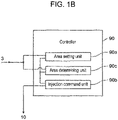
- Controller 90 controls opening and closing of injection nozzle 10 based on the material type, the position, and the size of resin piece 2 identified by identification unit 3. As illustrated in FIG. 1B , controller 90 includes area setting unit 90a, injection command unit 90b, and area determining unit 90c.
- Area setting unit 90a sets a setting injection area or a non-injection area for resin piece 2 based on the composition and the position information identified by identification unit 3. In detail, area setting unit 90a sets the setting injection area for specific material type object 2a, and sets the non-injection area for other material type object 2b.
- Injection command unit 90b outputs, to injection nozzle 10, a command of injecting the pulse air to an injection area set by area determining unit 90c, and injects the pulse air from injection nozzle 10 to the injection area.
- Injection nozzle 10 drives or stops driving of the pulse air according to widely-known opening and closing control of an opening and closing valve.
- Area determining unit 90c determines whether or not the setting injection area and the non-injection area overlap each other. When the setting injection area and the non-injection area overlap each other, area determining unit 90c sets the setting injection area other than the non-injection area as an injection area. In other words, a portion of the setting injection area where the setting injection area and the non-injection area do not overlap each other is set as the injection area. When the setting injection area and the non-injection area do not overlap each other, area determining unit 90c sets the setting injection area as the injection area.
- Resin piece 2 which is transported by conveyor 1 and reaches conveyor tip end portion 4 of conveyor 1 in the transport direction, jumps out from conveyor tip end portion 4 in the transport direction, for example, the horizontal direction, at the same speed as the transport speed of conveyor 1.
- Resin piece 2 thrown out from conveyor 1 in the horizontal direction falls freely.
- specific material type object 2a which is the corresponding specific material type resin, among resin piece 2
- the pulse air is injected from injection nozzle 10 according to a command from controller 90 based on the information from identification unit 3.
- controller 90 based on the information from identification unit 3.
- Other material type object 2b which are resins of the other material type object other than specific material type object 2a, are recovered in section 81B without the pulse air being injected and without being knocked down by the pulse air.
- range of resin piece 2 controller 90 outputs an injection command to injection nozzle 10 such that the pulse air is injected, based on the information obtained by identification unit 3, by area setting unit 90a, injection command unit 90b, and area determining unit 90c.
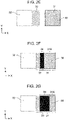
- FIG. 2A is a view of resin piece 30 of the specific material type placed on conveyor 1 when identification unit 3 identifies rectangular resin piece 30 of the specific material type, as viewed downward from the upper side of conveyor 1.
- the X axis of FIGS. 2A to 2G which will be described below, is the transport direction of conveyor 1, which is like FIG. 1A .
- area setting unit 90a of controller 90 sets rectangular setting injection area 31 as indicated by oblique lines for the entire range of resin piece 30.
- area setting unit 90a sets rectangular injection area 31 as indicated by oblique lines for the entire rectangular range.
- area setting unit 90a specifies the size and the position of resin piece 30 (corresponding to the specific material type object 2a in FIG. 1 ) of the specific material type, based on the information obtained by identification unit 3.
- area setting unit 90a specifies the size of resin piece 30 as the size of an area surrounded by solid line 30a.
- Area setting unit 90a sets setting injection area 31 as an area having the same size as resin piece 30 of the specific material type and as an oblique shaded area that is not surrounded by a line. Since there is no non-target resin piece on the rear side, area determining unit 90c determines that setting injection area 31 and non-injection area do not overlap each other. Therefore, area determining unit 90c sets setting injection area 31 set by area setting unit 90a as the injection area.
- Injection command unit 90b issues, to injection nozzle 10, a command for injecting the pulse air to the injection area set by area determining unit 90c.
- area setting unit 90a sets, as the setting injection area, a range having the same size as the size of specific material type object 2a.
- area setting unit 90a may set, as the setting injection area, a range that is larger or smaller than the size of specific material type object 2a.
- FIG. 2C is a schematic view of a case where rectangular non-target resin piece 32 is located behind resin piece 30 of the specific material type on conveyor 1 (in other words, on the left side of FIG. 2C (in a negative direction of the X axis)).
- area setting unit 90a specifics the size and the position of non-target resin piece 32 based on the information obtained by identification unit 3.
- the size of resin piece 32 on the X-Y plane is set as the size of an area surrounded by a broken line 32a.
- area setting unit 90a sets setting injection area 31 of rectangular resin piece 30 to be sorted of the specific material type, which is like FIG. 2B .
- Area setting unit 90a sets rectangular non-injection area 33 in front of non-target resin piece 32 (in other words, on the right side of FIG. 2E (in a positive direction of the X axis)).
- non-injection area 33 is set as an oblique shaded area that is not surrounded by a line.
- area setting unit 90a of controller 90 sets setting injection area 31 and non-injection area 33.
- Area determining unit 90c determines whether or not setting injection area 31 and non-injection area 33 set by area setting unit 90a overlap each other. In an example illustrated in FIG. 2E , area determining unit 90c determines that setting injection area 31 and non-injection area 33 do not overlap each other. Therefore, area determining unit 90c sets setting injection area 31 set by area setting unit 90a as the injection area.
- Injection command unit 90b issues, to injection nozzle 10, a command to inject the pulse air to the injection area set by area determining unit 90c.
- FIG. 2F illustrates an example where setting injection area 31 and non-injection area 33 overlap each other.
- area setting unit 90a sets setting injection area 31 and non-injection area 33, based on the upper side from identification unit 3.
- area determining unit 90c determines that setting injection area 31 and non-injection area 33 set by area setting unit 90a overlap each other. Therefore, area determining unit 90c determines that interference area 34 (corresponding to a black area of FIG. 2F ) where setting injection area 31 and non-injection area 33 overlap each other is an area that is not injected even in the setting injection area. That is, area determining unit 90c sets, as an injection area, area 31X obtained by removing interference area 34 from setting injection area 31.
- interference area 34 where setting injection area 31 and non-injection area 33 overlap each other may occupy most of the length of resin piece 30 of the specific material type in a flight direction.
- interference area 34 is an area that is not injected, injection area 31X with respect to an area of resin piece 30 of the specific material type on the X-Y plane is narrowed. Therefore, there is a possibility that resin piece 30 of the specific material type cannot be knocked down with high accuracy.
- injection command unit 90b can also perform injection control so as not to inject the pulse air even to resin piece 30 of the specific material type.
- the length of non-injection area 33 in the flight direction is determined by a ratio between the size of front and rear resin pieces 30 and the size of resin piece 32.
- the injection area becomes wide, and the amount of the pulse air injected toward resin piece 30 of the specific material type increases. Therefore, influence on rear non-target resin piece 32 increases.
- the size of rear non-target resin piece 32 is large, the momentum of resin piece 32 itself is large, and thus it is difficult that resin piece 32 is affected by the pulse air that is injected toward resin piece 30 of the specific material type.
- area setting unit 90a sets non-injection area 33 based on a ratio between the size of front and rear resin pieces 30 and the size of resin piece 32.
- FIG. 3 is a graph depicting a relationship between the length of non-injection area 33 in the flight direction and the size ratio between front resin piece 30 and rear resin piece 32.
- FIG. 3 illustrates a result of an experiment using an actual sorting apparatus. The graph illustrated in FIG. 3 was made by changing a ratio R between the size of resin piece 30 and the size of resin piece 32 and length L of non-injection area 33 in the flight direction and by identifying a range that does not affect the sorting.
- a horizontal axis R denotes a (front/rear) resin size ratio and is a value obtained by dividing the length of rear non-target resin piece 32 in the flight direction by the length of front resin piece 30 of the specific material type in the flight direction.
- a vertical axis L denotes the length of non-injection area 33 in the flight direction.
- a medium value is derived by logarithmically approximating an experimental value.
- the length of non-injection area 33 in the flight direction has a value obtained by adding 30% to the medium value, as an upper limit value, and has a value obtained by subtracting 30% from the medium value, as a lower limit value.
- This is a range in which even while non-target resin piece 32 is affected by the pulse air injected to the resin piece of the specific material type, non-target resin piece 32 continues to fly without being knocked down. Accordingly, non-target resin piece 32 is not mixed in section 81A illustrated in FIG. 1A . As a result, the purity of resin piece 30 of the specific material type sorted and recovered in section 81A is improved.
- area setting unit 90a may set a value obtained by adding 15% to the medium value as an upper limit value and a value obtained by subtracting 15% from the medium value as a lower limit value, as the length of non-injection area 33 in the flight direction.
- non-target resin piece 32 is not affected by the pulse air injected to the resin piece of the specific material type.
- the purity of resin piece 30 of the specific material type can be improved, and an area where non-injection area 33 overlaps setting injection area 31 can be reduced. Therefore, a probability that the pulse air can surely knock down resin piece 30 of the specific material type increases, and a recovery rate of resin piece 30 of the specific material type sorted and recovered in section 81A is improved.
- Area setting unit 90a of controller 90 firstly calculates an R that is the (rear/front) resin size ratio obtained by dividing the length of rear resin piece 32 in the flight direction measured by identification unit 3 by the length of front resin piece 30 in the flight direction. Then, area setting unit 90a calculates L that is the length of non-injection area 33 in the flight direction by substituting R into an equation of the medium value, based on the graph of FIG. 3
- area setting unit 90a may simply derive L using a conversion table with discrete values.
- area setting unit 90a may set non-injection area 33 substantially by setting a value of the (rear/front) resin size ratio R to 0.4 or more and 2.5 or less.
- a target value of a certain size is set and the resin is crushed into resin pieces. Therefore, in the crushing process, it is difficult to generate a resin piece having a small size or a large size that unintentionally departs from the target value. Therefore, with regard to the particle size of the resin piece, stochastically, the number of resin pieces having a size of the target value is the largest, and the number of resin pieces is gradually reduced as the sizes of the resin pieces become farther from the target value.
- the length of the non-injection area in the width direction (the Y axis direction) is set as the length of other material type object 2b (resin piece 32) in the width direction.
- area determining unit 90c makes the injection area of specific material type object 2a smaller than the area of specific material type object 2a.
- area determining unit 90c makes the injection area of specific material type object 2a on a placement plane smaller than the area of specific material type object 2a on the placement plane.
- the placement plane is the surface of conveyor 1, is a plane obtained by extending the surface on which resin piece 2 is placed, and is an X-Y plane.
- area determining unit 90c sets, as the injection area, an area obtained by removing a rear portion from an area of specific material type object 2a on the placement plane.
- FIG. 4 is a schematic view of sorting apparatus 41 having first nozzle group 11 and second nozzle group 12.
- a difference between the apparatus of FIG. 1A and the apparatus of FIG. 4 is that specific material type object 2a of a first specific material type is sorted using first nozzle group 11, specific material type object 2c of a second specific material type that is different from the first specific material type of first nozzle group 11 is knocked down using second nozzle group 12 and is recovered and sorted in section 81C.
- Other material type object 2b other than the specific material type object is not knocked down by first nozzle group 11 and second nozzle group 12 and is recovered in section 81B.
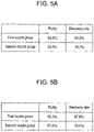
- FIGS. 5A and 5B are views illustrating examples where the purity and the recovery rate are improved by experiments using sorting apparatus 41 according to the exemplary embodiment of the present disclosure.
- FIG. 5A illustrates an experimental result when the non-injection area is not controlled in the same sorting apparatus as sorting apparatus 41 according to the exemplary embodiment of the present disclosure.
- FIG. 5B illustrates an experimental result when the non-injection area is controlled in the same sorting apparatus as sorting apparatus 41 according to the exemplary embodiment of the present disclosure.
- the purity (%) (the weight of the resin pieces of the specific material type among the resin pieces recovered in the partitioned sections/the weight of the resin pieces recovered in the partitioned sections) ⁇ 100.
- the recovery rate (%) (the weight of the resin pieces of the specific material type among the resin pieces recovered in the partitioned sections/the weight of the resin pieces of the specific material type contained in all the resin pieces before the sorting) ⁇ 100
- both the first nozzle group and the second nozzle group result in the improved purity and the improved recovery rate by applying the present disclosure.
- non-injection area 33 is provided at least in front of other material type object 2b other than the specific material type object on a rear extension line of specific material type object 2a in the transport direction, and injection nozzle 10 can be controlled to inject the pulse air from injection nozzle 10 to injection area 31 other than non-injection area 33.
- the sorting apparatus Accordingly, as compared to the related art, it is possible to recover a resin crushed to a smaller size, and it is possible to further promote the sorting and utilization of the resin.
Landscapes
- Engineering & Computer Science (AREA)
- Environmental & Geological Engineering (AREA)
- Mechanical Engineering (AREA)
- Sorting Of Articles (AREA)
Claims (5)
- Sortiervorrichtung (40), die ein Objekt (2a) eines spezifischen Materialtyps und ein Objekt (2b) eines anderen Materialtyps als das Objekt (2a) des spezifischen Materialtyps aus einem Sortierziel, in dem das Objekt (2a) des spezifischen Materialtyps und das Objekt (2b) des anderen Materialtyps gemischt sind, sortiert, wobei die Sortiervorrichtung (40) Folgendes umfasst:eine Transporteinheit (1), die das Sortierziel, das auf die Transporteinheit geladen ist, in eine Transportrichtung transportiert und das Sortierziel veranlasst, an einem Spitzenendabschnitt der Transporteinheit (1) zu fliegen;eine Identifikationseinheit (3), die über der Transporteinheit (1) angeordnet ist, zum Identifizieren eines Materialtyps, einer Position und einer Größe des Sortierziels;eine Injektionseinheit (10), die Luftimpulse zum Objekt (2a) des spezifischen Materialtyps injiziert; undeine Steuerung (90), die auf Basis des Materialtyps, der Position und der Größe, die durch die Identifikationseinheit (3) identifiziert werden, einen Injektionsbereich (31) der Luftimpulse, die zum Objekt (2a) des spezifischen Materialtyps zu injizieren sind, einstellt und die Injektionseinheit zum Injizieren der Luftimpulse in den Injektionsbereich (31) steuert,wobei die Steuerung (90) einen Bereich, der durch Entfernen eines hinteren Abschnitts aus einem Bereich des Objekts (2a, 30) des spezifischen Materialtyps auf einer Platzierungsebene, wenn das Objekt (2b, 32) des anderen Materialtyps in einem vorbestimmten Abstand von einer Rückseite des Objekts (2a, 30) des spezifischen Materialtyps vorhanden ist, erhalten wird, als den Injektionsbereich (31) einstellt,dadurch gekennzeichnet, dassdie Steuerung (90) einen Nichtinjektionsbereich (33) vor dem Objekt (2b, 32) des anderen Materialtyps auf einer hinteren Verlängerungslinie des Objekts (2a, 30) des spezifischen Materialtyps einstellt und einen Bereich (31X), der durch Entfernen des Nichtinjektionsbereichs (33) aus dem Bereich des Objekts (2a, 30) des spezifischen Materialtyps auf der Platzierungsebene erhalten wird, als den Injektionsbereich einstellt.
- Sortiervorrichtung nach Anspruch 1,wobei die Steuerung (90) Folgendes beinhalteteine Bereichseinstelleinheit (90a), die den Nichtinjektionsbereich einstellt, undeine Injektionsbefehlseinheit (90b), die die Injektionseinheit zum Injizieren der Luftimpulse in den Injektionsbereich steuert.
- Sortiervorrichtung nach Anspruch 2,wobei die Steuerung (90) ferner eine Bereichsbestimmungseinheit (90c) beinhaltet, die bestimmt, ob der Bereich des Objekts (2a, 30) des spezifischen Materialtyps auf der Platzierungsebene und der Nichtinjektionsbereich (33) einander überlappen oder nicht, unddie Bereichsbestimmungseinheit (90c) stellt einen Bereich, der durch Entfernen eines Überlappungsbereichs (34) aus dem Bereich (31) des Objekts (2a, 30) des spezifischen Materialtyps auf der Platzierungsebene, wenn bestimmt wird, dass der Bereich des Objekts (2a, 30) des spezifischen Materialtyps auf der Platzierungsebene und der Nichtinjektionsbereich (33) einander überlappen, erhalten wird, als den Injektionsbereich ein.
- Sortiervorrichtung nach einem der Ansprüche 1 bis 3,
wobei die Steuerung (90) eine Region des Nichtinjektionsbereichs (33) gemäß einem Verhältnis zwischen einer Größe des Objekts (2a, 30) des spezifischen Materialtyps und einer Größe des Objekts (2b, 32) des anderen Materialtyps einstellt, wobei sich das Objekt (2a, 30) des spezifischen Materialtyps in der einen Transportrichtung vor dem Objekt (2b, 32) des anderen Materialtyps befindet. - Sortiervorrichtung nach Anspruch 4,
wobei die Steuerung (90) unter Verwendung einer Logarithmusfunktion für R, das ein Wert ist, der durch Teilen einer Länge des hinteren Objekts (2b, 32) des anderen Materialtyps in der einen Transportrichtung durch eine Länge des vorderen Objekts (2a, 30) des spezifischen Materialtyps in der einen Transportrichtung erhalten wird, einen Mittelwert einer Länge L des Nichtinjektionsbereichs (33) in der einen Transportrichtung einstellt und die Länge L in einer Region einstellt, in der ein oberer Grenzwert der Länge L der Mittelwert + 30 % ist und der untere Grenzwert der Länge L der Mittelwert - 30 % ist.
Applications Claiming Priority (1)
| Application Number | Priority Date | Filing Date | Title |
|---|---|---|---|
| JP2018220863A JP6931805B2 (ja) | 2018-11-27 | 2018-11-27 | 選別装置 |
Publications (2)
| Publication Number | Publication Date |
|---|---|
| EP3659720A1 EP3659720A1 (de) | 2020-06-03 |
| EP3659720B1 true EP3659720B1 (de) | 2022-06-22 |
Family
ID=68392845
Family Applications (1)
| Application Number | Title | Priority Date | Filing Date |
|---|---|---|---|
| EP19206085.3A Active EP3659720B1 (de) | 2018-11-27 | 2019-10-30 | Sortiervorrichtung |
Country Status (3)
| Country | Link |
|---|---|
| EP (1) | EP3659720B1 (de) |
| JP (1) | JP6931805B2 (de) |
| CN (1) | CN111215354B (de) |
Families Citing this family (4)
| Publication number | Priority date | Publication date | Assignee | Title |
|---|---|---|---|---|
| CN114082682B (zh) * | 2022-01-18 | 2022-04-22 | 北矿机电科技有限责任公司 | 矿石分选分料器及拣选机 |
| CN116140243B (zh) * | 2023-04-18 | 2023-08-15 | 北京霍里思特科技有限公司 | 一种矿用喷吹的分选方法、分选系统、设备和存储介质 |
| WO2024217407A1 (zh) * | 2023-04-18 | 2024-10-24 | 北京霍里思特科技有限公司 | 一种矿用喷吹的分选方法、分选系统、分选设备 |
| CN118594975A (zh) * | 2023-12-20 | 2024-09-06 | 北京霍里思特科技有限公司 | 物块分选系统的控制方法及物块分选系统 |
Family Cites Families (25)
| Publication number | Priority date | Publication date | Assignee | Title |
|---|---|---|---|---|
| JPH0641876U (ja) * | 1992-11-17 | 1994-06-03 | 鐘紡株式会社 | 選別装置 |
| US5659624A (en) * | 1995-09-01 | 1997-08-19 | Fazzari; Rodney J. | High speed mass flow food sorting appartus for optically inspecting and sorting bulk food products |
| JP4461520B2 (ja) * | 1998-11-04 | 2010-05-12 | 株式会社サタケ | 粒状物色彩選別方法及び粒状物色彩選別装置 |
| JP4023331B2 (ja) * | 2002-06-03 | 2007-12-19 | ソニー株式会社 | 液体吐出装置及び液体吐出方法 |
| JP2004049991A (ja) * | 2002-07-17 | 2004-02-19 | Shin Meiwa Ind Co Ltd | 容器選別装置 |
| DE102004015468A1 (de) * | 2004-03-26 | 2005-10-20 | Hauni Primary Gmbh | Verfahren und Vorrichtung zur Fremdkörperabscheidung aus einem Tabakstrom |
| JP2010094634A (ja) * | 2008-10-17 | 2010-04-30 | Canon Inc | プラスチックの分別装置および分別方法 |
| JP2010247154A (ja) * | 2009-04-13 | 2010-11-04 | Ackley Machine Corp | 排出システム |
| JP5569799B2 (ja) * | 2010-06-18 | 2014-08-13 | 株式会社サタケ | 色彩選別機 |
| NL2005216C2 (nl) * | 2010-08-11 | 2012-02-20 | Optiserve B V | Sorteerinrichting en werkwijze voor het scheiden van producten in een bulkstroom van niet-homogene producten. |
| AT13420U1 (de) * | 2010-12-20 | 2013-12-15 | Binder Co Ag | Verfahren und vorrichtung zur sortierung |
| CN102680491B (zh) * | 2012-05-04 | 2014-05-14 | 新昌县航达机械制造有限公司 | 一种剔除式智能胶囊检测机 |
| JP6098881B2 (ja) * | 2013-05-30 | 2017-03-22 | パナソニックIpマネジメント株式会社 | 選別装置 |
| KR20150039544A (ko) * | 2013-10-02 | 2015-04-10 | 조연상 | 제설장비 |
| CN204148153U (zh) * | 2014-10-09 | 2015-02-11 | 沈阳溯元智能装备有限公司 | 一种多通道色选机 |
| JP6283958B2 (ja) | 2015-05-14 | 2018-02-28 | パナソニックIpマネジメント株式会社 | 選別装置 |
| CN204769593U (zh) * | 2015-07-06 | 2015-11-18 | 汤小牛 | 气动打料的检重秤 |
| JP6472058B2 (ja) * | 2016-03-29 | 2019-02-20 | 富士フイルム株式会社 | 画像形成装置及び画像補正方法 |
| JP6732561B2 (ja) * | 2016-06-23 | 2020-07-29 | ワイエムシステムズ株式会社 | 豆類選別装置、及び豆類選別方法 |
| US9785851B1 (en) * | 2016-06-30 | 2017-10-10 | Huron Valley Steel Corporation | Scrap sorting system |
| CN206199715U (zh) * | 2016-11-04 | 2017-05-31 | 临武县华湘再生资源回收有限公司 | 塑料瓶片色选机 |
| CN108393278B (zh) * | 2017-02-06 | 2019-08-30 | 合肥美亚光电技术股份有限公司 | 色选机的象元划分装置及色选机 |
| DE112018001148T5 (de) * | 2017-03-30 | 2019-12-05 | Fujifilm Corporation | Bildverarbeitungsverfahren, bildverarbeitungsvorrichtung und bildaufzeichnungsvorrichtung |
| CN107138432B (zh) * | 2017-04-05 | 2020-03-13 | 杭州迦智科技有限公司 | 非刚性物体分拣方法和装置 |
| CN108499904A (zh) * | 2018-03-28 | 2018-09-07 | 合肥欣畅源光电科技有限公司 | 建筑垃圾砖砼骨料分选装置及方法 |
-
2018
- 2018-11-27 JP JP2018220863A patent/JP6931805B2/ja active Active
-
2019
- 2019-10-30 EP EP19206085.3A patent/EP3659720B1/de active Active
- 2019-11-22 CN CN201911163695.4A patent/CN111215354B/zh active Active
Also Published As
| Publication number | Publication date |
|---|---|
| CN111215354A (zh) | 2020-06-02 |
| EP3659720A1 (de) | 2020-06-03 |
| JP6931805B2 (ja) | 2021-09-08 |
| JP2020081974A (ja) | 2020-06-04 |
| CN111215354B (zh) | 2021-10-08 |
Similar Documents
| Publication | Publication Date | Title |
|---|---|---|
| EP3659720B1 (de) | Sortiervorrichtung | |
| CN105710998B (zh) | 分选装置 | |
| EP3093076B1 (de) | Sortiervorrichtung | |
| US6696655B2 (en) | Device and method for sorting out metal fractions from a stream of bulk material | |
| CN105358266B (zh) | 物质的分选装置、分选方法 | |
| EP2808096B1 (de) | Trennverfahren | |
| WO2023202258A1 (zh) | 一种物料分选系统及分选方法 | |
| CN113500015B (zh) | 一种基于分级阵列式智能分选进行矿石预选的方法及系统 | |
| KR101965425B1 (ko) | 비파쇄 재활용 플라스틱 선별장치 | |
| CN206578043U (zh) | 三产品智能干选机 | |
| CN104858154A (zh) | 一种金属拣选装置 | |
| CN117443748A (zh) | 一种物块分选系统的控制方法及物块分选系统 | |
| WO2023202260A1 (zh) | 一种物料分选系统及分选方法 | |
| TWM655317U (zh) | 一種飲料瓶分選裝置 | |
| CN208882801U (zh) | 一种物流分拣机的进料输送线 | |
| JP2011173049A (ja) | 分別方法、および、分別装置 | |
| CN105818300A (zh) | 混合塑料红外识别分选设备 | |
| US3750881A (en) | Color sorter | |
| CN112588613A (zh) | 矿物智能分选系统及方法 | |
| CN223717722U (zh) | 一种物料分拣执行系统 | |
| CN219581091U (zh) | 用于物料分选机的分类回收装置及物料分选机 | |
| CN108554646A (zh) | 一种浮选机的差异化配置系统 | |
| Kravtsova et al. | An effective system for recycling polyethyleneterephthalate | |
| Clarke | Sorting it out: tackling the problem of packaging waste | |
| CN117157150A (zh) | 材料分离系统 |
Legal Events
| Date | Code | Title | Description |
|---|---|---|---|
| PUAI | Public reference made under article 153(3) epc to a published international application that has entered the european phase |
Free format text: ORIGINAL CODE: 0009012 |
|
| STAA | Information on the status of an ep patent application or granted ep patent |
Free format text: STATUS: THE APPLICATION HAS BEEN PUBLISHED |
|
| AK | Designated contracting states |
Kind code of ref document: A1 Designated state(s): AL AT BE BG CH CY CZ DE DK EE ES FI FR GB GR HR HU IE IS IT LI LT LU LV MC MK MT NL NO PL PT RO RS SE SI SK SM TR |
|
| AX | Request for extension of the european patent |
Extension state: BA ME |
|
| STAA | Information on the status of an ep patent application or granted ep patent |
Free format text: STATUS: REQUEST FOR EXAMINATION WAS MADE |
|
| 17P | Request for examination filed |
Effective date: 20201008 |
|
| RBV | Designated contracting states (corrected) |
Designated state(s): AL AT BE BG CH CY CZ DE DK EE ES FI FR GB GR HR HU IE IS IT LI LT LU LV MC MK MT NL NO PL PT RO RS SE SI SK SM TR |
|
| STAA | Information on the status of an ep patent application or granted ep patent |
Free format text: STATUS: EXAMINATION IS IN PROGRESS |
|
| 17Q | First examination report despatched |
Effective date: 20210914 |
|
| GRAP | Despatch of communication of intention to grant a patent |
Free format text: ORIGINAL CODE: EPIDOSNIGR1 |
|
| STAA | Information on the status of an ep patent application or granted ep patent |
Free format text: STATUS: GRANT OF PATENT IS INTENDED |
|
| INTG | Intention to grant announced |
Effective date: 20220331 |
|
| GRAS | Grant fee paid |
Free format text: ORIGINAL CODE: EPIDOSNIGR3 |
|
| GRAA | (expected) grant |
Free format text: ORIGINAL CODE: 0009210 |
|
| STAA | Information on the status of an ep patent application or granted ep patent |
Free format text: STATUS: THE PATENT HAS BEEN GRANTED |
|
| AK | Designated contracting states |
Kind code of ref document: B1 Designated state(s): AL AT BE BG CH CY CZ DE DK EE ES FI FR GB GR HR HU IE IS IT LI LT LU LV MC MK MT NL NO PL PT RO RS SE SI SK SM TR |
|
| REG | Reference to a national code |
Ref country code: GB Ref legal event code: FG4D |
|
| REG | Reference to a national code |
Ref country code: CH Ref legal event code: EP |
|
| REG | Reference to a national code |
Ref country code: DE Ref legal event code: R096 Ref document number: 602019016115 Country of ref document: DE |
|
| REG | Reference to a national code |
Ref country code: AT Ref legal event code: REF Ref document number: 1499429 Country of ref document: AT Kind code of ref document: T Effective date: 20220715 |
|
| REG | Reference to a national code |
Ref country code: IE Ref legal event code: FG4D |
|
| REG | Reference to a national code |
Ref country code: LT Ref legal event code: MG9D |
|
| REG | Reference to a national code |
Ref country code: NL Ref legal event code: MP Effective date: 20220622 |
|
| PG25 | Lapsed in a contracting state [announced via postgrant information from national office to epo] |
Ref country code: SE Free format text: LAPSE BECAUSE OF FAILURE TO SUBMIT A TRANSLATION OF THE DESCRIPTION OR TO PAY THE FEE WITHIN THE PRESCRIBED TIME-LIMIT Effective date: 20220622 Ref country code: NO Free format text: LAPSE BECAUSE OF FAILURE TO SUBMIT A TRANSLATION OF THE DESCRIPTION OR TO PAY THE FEE WITHIN THE PRESCRIBED TIME-LIMIT Effective date: 20220922 Ref country code: LT Free format text: LAPSE BECAUSE OF FAILURE TO SUBMIT A TRANSLATION OF THE DESCRIPTION OR TO PAY THE FEE WITHIN THE PRESCRIBED TIME-LIMIT Effective date: 20220622 Ref country code: HR Free format text: LAPSE BECAUSE OF FAILURE TO SUBMIT A TRANSLATION OF THE DESCRIPTION OR TO PAY THE FEE WITHIN THE PRESCRIBED TIME-LIMIT Effective date: 20220622 Ref country code: GR Free format text: LAPSE BECAUSE OF FAILURE TO SUBMIT A TRANSLATION OF THE DESCRIPTION OR TO PAY THE FEE WITHIN THE PRESCRIBED TIME-LIMIT Effective date: 20220923 Ref country code: FI Free format text: LAPSE BECAUSE OF FAILURE TO SUBMIT A TRANSLATION OF THE DESCRIPTION OR TO PAY THE FEE WITHIN THE PRESCRIBED TIME-LIMIT Effective date: 20220622 Ref country code: BG Free format text: LAPSE BECAUSE OF FAILURE TO SUBMIT A TRANSLATION OF THE DESCRIPTION OR TO PAY THE FEE WITHIN THE PRESCRIBED TIME-LIMIT Effective date: 20220922 |
|
| REG | Reference to a national code |
Ref country code: AT Ref legal event code: MK05 Ref document number: 1499429 Country of ref document: AT Kind code of ref document: T Effective date: 20220622 |
|
| PG25 | Lapsed in a contracting state [announced via postgrant information from national office to epo] |
Ref country code: RS Free format text: LAPSE BECAUSE OF FAILURE TO SUBMIT A TRANSLATION OF THE DESCRIPTION OR TO PAY THE FEE WITHIN THE PRESCRIBED TIME-LIMIT Effective date: 20220622 Ref country code: LV Free format text: LAPSE BECAUSE OF FAILURE TO SUBMIT A TRANSLATION OF THE DESCRIPTION OR TO PAY THE FEE WITHIN THE PRESCRIBED TIME-LIMIT Effective date: 20220622 |
|
| PG25 | Lapsed in a contracting state [announced via postgrant information from national office to epo] |
Ref country code: NL Free format text: LAPSE BECAUSE OF FAILURE TO SUBMIT A TRANSLATION OF THE DESCRIPTION OR TO PAY THE FEE WITHIN THE PRESCRIBED TIME-LIMIT Effective date: 20220622 |
|
| PG25 | Lapsed in a contracting state [announced via postgrant information from national office to epo] |
Ref country code: SM Free format text: LAPSE BECAUSE OF FAILURE TO SUBMIT A TRANSLATION OF THE DESCRIPTION OR TO PAY THE FEE WITHIN THE PRESCRIBED TIME-LIMIT Effective date: 20220622 Ref country code: SK Free format text: LAPSE BECAUSE OF FAILURE TO SUBMIT A TRANSLATION OF THE DESCRIPTION OR TO PAY THE FEE WITHIN THE PRESCRIBED TIME-LIMIT Effective date: 20220622 Ref country code: RO Free format text: LAPSE BECAUSE OF FAILURE TO SUBMIT A TRANSLATION OF THE DESCRIPTION OR TO PAY THE FEE WITHIN THE PRESCRIBED TIME-LIMIT Effective date: 20220622 Ref country code: PT Free format text: LAPSE BECAUSE OF FAILURE TO SUBMIT A TRANSLATION OF THE DESCRIPTION OR TO PAY THE FEE WITHIN THE PRESCRIBED TIME-LIMIT Effective date: 20221024 Ref country code: ES Free format text: LAPSE BECAUSE OF FAILURE TO SUBMIT A TRANSLATION OF THE DESCRIPTION OR TO PAY THE FEE WITHIN THE PRESCRIBED TIME-LIMIT Effective date: 20220622 Ref country code: EE Free format text: LAPSE BECAUSE OF FAILURE TO SUBMIT A TRANSLATION OF THE DESCRIPTION OR TO PAY THE FEE WITHIN THE PRESCRIBED TIME-LIMIT Effective date: 20220622 Ref country code: CZ Free format text: LAPSE BECAUSE OF FAILURE TO SUBMIT A TRANSLATION OF THE DESCRIPTION OR TO PAY THE FEE WITHIN THE PRESCRIBED TIME-LIMIT Effective date: 20220622 Ref country code: AT Free format text: LAPSE BECAUSE OF FAILURE TO SUBMIT A TRANSLATION OF THE DESCRIPTION OR TO PAY THE FEE WITHIN THE PRESCRIBED TIME-LIMIT Effective date: 20220622 |
|
| PG25 | Lapsed in a contracting state [announced via postgrant information from national office to epo] |
Ref country code: PL Free format text: LAPSE BECAUSE OF FAILURE TO SUBMIT A TRANSLATION OF THE DESCRIPTION OR TO PAY THE FEE WITHIN THE PRESCRIBED TIME-LIMIT Effective date: 20220622 Ref country code: IS Free format text: LAPSE BECAUSE OF FAILURE TO SUBMIT A TRANSLATION OF THE DESCRIPTION OR TO PAY THE FEE WITHIN THE PRESCRIBED TIME-LIMIT Effective date: 20221022 |
|
| REG | Reference to a national code |
Ref country code: DE Ref legal event code: R097 Ref document number: 602019016115 Country of ref document: DE |
|
| PG25 | Lapsed in a contracting state [announced via postgrant information from national office to epo] |
Ref country code: AL Free format text: LAPSE BECAUSE OF FAILURE TO SUBMIT A TRANSLATION OF THE DESCRIPTION OR TO PAY THE FEE WITHIN THE PRESCRIBED TIME-LIMIT Effective date: 20220622 |
|
| PG25 | Lapsed in a contracting state [announced via postgrant information from national office to epo] |
Ref country code: DK Free format text: LAPSE BECAUSE OF FAILURE TO SUBMIT A TRANSLATION OF THE DESCRIPTION OR TO PAY THE FEE WITHIN THE PRESCRIBED TIME-LIMIT Effective date: 20220622 |
|
| PLBE | No opposition filed within time limit |
Free format text: ORIGINAL CODE: 0009261 |
|
| STAA | Information on the status of an ep patent application or granted ep patent |
Free format text: STATUS: NO OPPOSITION FILED WITHIN TIME LIMIT |
|
| 26N | No opposition filed |
Effective date: 20230323 |
|
| PG25 | Lapsed in a contracting state [announced via postgrant information from national office to epo] |
Ref country code: MC Free format text: LAPSE BECAUSE OF FAILURE TO SUBMIT A TRANSLATION OF THE DESCRIPTION OR TO PAY THE FEE WITHIN THE PRESCRIBED TIME-LIMIT Effective date: 20220622 |
|
| REG | Reference to a national code |
Ref country code: CH Ref legal event code: PL |
|
| REG | Reference to a national code |
Ref country code: BE Ref legal event code: MM Effective date: 20221031 |
|
| PG25 | Lapsed in a contracting state [announced via postgrant information from national office to epo] |
Ref country code: LU Free format text: LAPSE BECAUSE OF NON-PAYMENT OF DUE FEES Effective date: 20221030 |
|
| PG25 | Lapsed in a contracting state [announced via postgrant information from national office to epo] |
Ref country code: LI Free format text: LAPSE BECAUSE OF NON-PAYMENT OF DUE FEES Effective date: 20221031 Ref country code: FR Free format text: LAPSE BECAUSE OF NON-PAYMENT OF DUE FEES Effective date: 20221031 Ref country code: CH Free format text: LAPSE BECAUSE OF NON-PAYMENT OF DUE FEES Effective date: 20221031 |
|
| PG25 | Lapsed in a contracting state [announced via postgrant information from national office to epo] |
Ref country code: SI Free format text: LAPSE BECAUSE OF FAILURE TO SUBMIT A TRANSLATION OF THE DESCRIPTION OR TO PAY THE FEE WITHIN THE PRESCRIBED TIME-LIMIT Effective date: 20220622 |
|
| PG25 | Lapsed in a contracting state [announced via postgrant information from national office to epo] |
Ref country code: BE Free format text: LAPSE BECAUSE OF NON-PAYMENT OF DUE FEES Effective date: 20221031 |
|
| PG25 | Lapsed in a contracting state [announced via postgrant information from national office to epo] |
Ref country code: IE Free format text: LAPSE BECAUSE OF NON-PAYMENT OF DUE FEES Effective date: 20221030 |
|
| PG25 | Lapsed in a contracting state [announced via postgrant information from national office to epo] |
Ref country code: IT Free format text: LAPSE BECAUSE OF FAILURE TO SUBMIT A TRANSLATION OF THE DESCRIPTION OR TO PAY THE FEE WITHIN THE PRESCRIBED TIME-LIMIT Effective date: 20220622 |
|
| PG25 | Lapsed in a contracting state [announced via postgrant information from national office to epo] |
Ref country code: HU Free format text: LAPSE BECAUSE OF FAILURE TO SUBMIT A TRANSLATION OF THE DESCRIPTION OR TO PAY THE FEE WITHIN THE PRESCRIBED TIME-LIMIT; INVALID AB INITIO Effective date: 20191030 |
|
| PG25 | Lapsed in a contracting state [announced via postgrant information from national office to epo] |
Ref country code: CY Free format text: LAPSE BECAUSE OF FAILURE TO SUBMIT A TRANSLATION OF THE DESCRIPTION OR TO PAY THE FEE WITHIN THE PRESCRIBED TIME-LIMIT Effective date: 20220622 |
|
| PG25 | Lapsed in a contracting state [announced via postgrant information from national office to epo] |
Ref country code: MK Free format text: LAPSE BECAUSE OF FAILURE TO SUBMIT A TRANSLATION OF THE DESCRIPTION OR TO PAY THE FEE WITHIN THE PRESCRIBED TIME-LIMIT Effective date: 20220622 |
|
| GBPC | Gb: european patent ceased through non-payment of renewal fee |
Effective date: 20231030 |
|
| PG25 | Lapsed in a contracting state [announced via postgrant information from national office to epo] |
Ref country code: TR Free format text: LAPSE BECAUSE OF FAILURE TO SUBMIT A TRANSLATION OF THE DESCRIPTION OR TO PAY THE FEE WITHIN THE PRESCRIBED TIME-LIMIT Effective date: 20220622 |
|
| PG25 | Lapsed in a contracting state [announced via postgrant information from national office to epo] |
Ref country code: GB Free format text: LAPSE BECAUSE OF NON-PAYMENT OF DUE FEES Effective date: 20231030 |
|
| PG25 | Lapsed in a contracting state [announced via postgrant information from national office to epo] |
Ref country code: GB Free format text: LAPSE BECAUSE OF NON-PAYMENT OF DUE FEES Effective date: 20231030 |
|
| PG25 | Lapsed in a contracting state [announced via postgrant information from national office to epo] |
Ref country code: MT Free format text: LAPSE BECAUSE OF FAILURE TO SUBMIT A TRANSLATION OF THE DESCRIPTION OR TO PAY THE FEE WITHIN THE PRESCRIBED TIME-LIMIT Effective date: 20220622 |
|
| PG25 | Lapsed in a contracting state [announced via postgrant information from national office to epo] |
Ref country code: BG Free format text: LAPSE BECAUSE OF FAILURE TO SUBMIT A TRANSLATION OF THE DESCRIPTION OR TO PAY THE FEE WITHIN THE PRESCRIBED TIME-LIMIT Effective date: 20220622 |
|
| PG25 | Lapsed in a contracting state [announced via postgrant information from national office to epo] |
Ref country code: BG Free format text: LAPSE BECAUSE OF FAILURE TO SUBMIT A TRANSLATION OF THE DESCRIPTION OR TO PAY THE FEE WITHIN THE PRESCRIBED TIME-LIMIT Effective date: 20220622 |
|
| PGFP | Annual fee paid to national office [announced via postgrant information from national office to epo] |
Ref country code: DE Payment date: 20251021 Year of fee payment: 7 |