EP3093076B1 - Sortiervorrichtung - Google Patents
Sortiervorrichtung Download PDFInfo
- Publication number
- EP3093076B1 EP3093076B1 EP16166693.8A EP16166693A EP3093076B1 EP 3093076 B1 EP3093076 B1 EP 3093076B1 EP 16166693 A EP16166693 A EP 16166693A EP 3093076 B1 EP3093076 B1 EP 3093076B1
- Authority
- EP
- European Patent Office
- Prior art keywords
- conveyor
- wind velocity
- airflow
- flight path
- resin pieces
- Prior art date
- Legal status (The legal status is an assumption and is not a legal conclusion. Google has not performed a legal analysis and makes no representation as to the accuracy of the status listed.)
- Active
Links
Images


Classifications
-
- B—PERFORMING OPERATIONS; TRANSPORTING
- B07—SEPARATING SOLIDS FROM SOLIDS; SORTING
- B07C—POSTAL SORTING; SORTING INDIVIDUAL ARTICLES, OR BULK MATERIAL FIT TO BE SORTED PIECE-MEAL, e.g. BY PICKING
- B07C5/00—Sorting according to a characteristic or feature of the articles or material being sorted, e.g. by control effected by devices which detect or measure such characteristic or feature; Sorting by manually actuated devices, e.g. switches
- B07C5/34—Sorting according to other particular properties
- B07C5/342—Sorting according to other particular properties according to optical properties, e.g. colour
- B07C5/3422—Sorting according to other particular properties according to optical properties, e.g. colour using video scanning devices, e.g. TV-cameras
-
- B—PERFORMING OPERATIONS; TRANSPORTING
- B07—SEPARATING SOLIDS FROM SOLIDS; SORTING
- B07C—POSTAL SORTING; SORTING INDIVIDUAL ARTICLES, OR BULK MATERIAL FIT TO BE SORTED PIECE-MEAL, e.g. BY PICKING
- B07C5/00—Sorting according to a characteristic or feature of the articles or material being sorted, e.g. by control effected by devices which detect or measure such characteristic or feature; Sorting by manually actuated devices, e.g. switches
- B07C5/36—Sorting apparatus characterised by the means used for distribution
- B07C5/363—Sorting apparatus characterised by the means used for distribution by means of air
- B07C5/367—Sorting apparatus characterised by the means used for distribution by means of air using a plurality of separation means
- B07C5/368—Sorting apparatus characterised by the means used for distribution by means of air using a plurality of separation means actuated independently
-
- B—PERFORMING OPERATIONS; TRANSPORTING
- B07—SEPARATING SOLIDS FROM SOLIDS; SORTING
- B07C—POSTAL SORTING; SORTING INDIVIDUAL ARTICLES, OR BULK MATERIAL FIT TO BE SORTED PIECE-MEAL, e.g. BY PICKING
- B07C5/00—Sorting according to a characteristic or feature of the articles or material being sorted, e.g. by control effected by devices which detect or measure such characteristic or feature; Sorting by manually actuated devices, e.g. switches
- B07C5/02—Measures preceding sorting, e.g. arranging articles in a stream orientating
-
- B—PERFORMING OPERATIONS; TRANSPORTING
- B07—SEPARATING SOLIDS FROM SOLIDS; SORTING
- B07C—POSTAL SORTING; SORTING INDIVIDUAL ARTICLES, OR BULK MATERIAL FIT TO BE SORTED PIECE-MEAL, e.g. BY PICKING
- B07C5/00—Sorting according to a characteristic or feature of the articles or material being sorted, e.g. by control effected by devices which detect or measure such characteristic or feature; Sorting by manually actuated devices, e.g. switches
- B07C5/34—Sorting according to other particular properties
-
- B—PERFORMING OPERATIONS; TRANSPORTING
- B07—SEPARATING SOLIDS FROM SOLIDS; SORTING
- B07C—POSTAL SORTING; SORTING INDIVIDUAL ARTICLES, OR BULK MATERIAL FIT TO BE SORTED PIECE-MEAL, e.g. BY PICKING
- B07C5/00—Sorting according to a characteristic or feature of the articles or material being sorted, e.g. by control effected by devices which detect or measure such characteristic or feature; Sorting by manually actuated devices, e.g. switches
- B07C5/36—Sorting apparatus characterised by the means used for distribution
- B07C5/361—Processing or control devices therefor, e.g. escort memory
- B07C5/362—Separating or distributor mechanisms
-
- B—PERFORMING OPERATIONS; TRANSPORTING
- B07—SEPARATING SOLIDS FROM SOLIDS; SORTING
- B07C—POSTAL SORTING; SORTING INDIVIDUAL ARTICLES, OR BULK MATERIAL FIT TO BE SORTED PIECE-MEAL, e.g. BY PICKING
- B07C5/00—Sorting according to a characteristic or feature of the articles or material being sorted, e.g. by control effected by devices which detect or measure such characteristic or feature; Sorting by manually actuated devices, e.g. switches
- B07C5/36—Sorting apparatus characterised by the means used for distribution
- B07C5/363—Sorting apparatus characterised by the means used for distribution by means of air
- B07C5/365—Sorting apparatus characterised by the means used for distribution by means of air using a single separation means
- B07C5/366—Sorting apparatus characterised by the means used for distribution by means of air using a single separation means during free fall of the articles
Definitions
- the present disclosure relates to a sorting device that sorts small pieces made of a specific material type from sorting objects constituted by collecting a plurality of small pieces, and particularly, relates to a sorting device that sorts small pieces of a specific resin type from sorting objects obtained by crushing used home electric appliances or the like.
- a useless home electric appliance is crushed into small pieces in a home electric recycling factory, and then the small pieces are separated by material type, using magnetism, wind power, vibration or the like for resource recovery.
- a specific gravity sorting device or a magnetic sorting device allows small pieces made of metal to be separated with high purity by material type such as iron, copper, aluminum and the like, which realizes a high resource recovery rate.
- Patent Literature 1 A sorting method in view of the above-described problems regarding the resource recovery of the resin materials has been proposed in Patent Literature 1.
- a material type is detected by an identification device, which enables two types of small pieces made of resin materials that cannot be sorted in the specific gravity sorting to be simultaneously sorted.
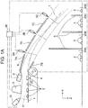
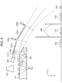
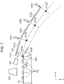
- FIG. 6 is a schematic configuration diagram of a conventional sorting device according to Patent Literature 1.
- This sorting device sorts a specific material type matter and another material type matter from sorting objects in which the specific material type matter and the other material type matter other than the specific material type matter are mixed.
- Conveyor 101 conveys small resin pieces 102 as the sorting objects placed on conveyor 101 in one direction. Composition of small resin pieces 102 is identified, and at the same time, position information on conveyor 101 is acquired when small resin pieces 102 pass under identification device 103.
- Small resin pieces 102 that have reached conveyor forefront portion 104 in a conveyance direction of conveyor 101 fly out horizontally at the same velocity as conveyance velocity V100 of conveyor 101.
- first assist nozzle 106 that generates airflow 109 at wind velocity V101 that matches conveyance velocity V100 of conveyor 101 is disposed.
- First upper rectifying plates 107A are disposed along a flight path of small resin pieces 102 above the flight path, and lower rectifying plate 107B is disposed along the flight path obliquely below conveyor forefront portion 104 under the flight path of small resin pieces 102.
- the above-described configuration enables airflow 109 at the wind velocity that matches the conveyance velocity of conveyor 101 to flow along the flight path of small resin pieces 102 inside the flight path.
- first assist nozzle 106, first upper rectifying plates 107A, and lower rectifying plate 107B are absent, small resin pieces 102 receive the same wind velocity V100 as the conveyance velocity of conveyor 101 from a front in a travelling direction immediately after flying out from conveyor 101, and they receive air resistive force differently, depending on shapes, areas, or weights of small resin pieces 102. In this case, since the flight path differs in respective small resin pieces 102, flight variation is caused, which decreases shooting accuracy at the positions where small resin pieces 102 receive the pulse air of first nozzle group 105A and second nozzle group 105B described later.
- first assist nozzle 106 supplies airflow 109 at window velocity V101 matching the conveyance velocity of conveyor 101 in the flying-out direction of small resin pieces 102, and thus, a relative velocity between small resin pieces 102 and airflow 109 at the time of flying-out is almost 0, and the air resistance is also almost 0.
- first upper rectifying plates 107A and lower rectifying plate 107B maintain airflow 109 at window velocity V101 matching conveyance velocity V100 of conveyor 101 along the flight path, the flight in a state where the air resistance is almost 0 is realized across the flight path.
- This action can prevent small resin pieces 102 from receiving the air resistive force inside the flight path regardless of the shapes, the areas, or weights of the resin, thereby suppressing the flight variation of the resin.
- the above configuration enables two types of the specific material type matters and the other material type matter to be simultaneously sorted with high accuracy from the sorting objects in which the specific material type matters and the other material type matter are mixed.
- second upper rectifying plate 107C is installed next to first upper rectifying plate 107A along flight path to extend a rectifying effect, and third nozzle group 105C is installed to consider the sorting accuracy.
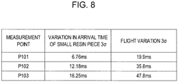
- small resin pieces 102 resins different in size that are 10 mm squares to 100 mm squares are used, because the resins having small grain sizes produced when home electric appliance resins are crushed into small pieces by a crusher are objects.
- HAS-L1M 500FPS by DITECT high-speed camera
- a shift by up to 19.9 mm is caused at position P101 where the pulse air of first nozzle group 105A is received
- a shift by up to 35.8 mm is caused at position P102 where the pulse air of second nozzle group 105B is received
- a shift by up to 47.8 mm is caused at position P103 where the pulse air of third nozzle group 105C is received.
- the flight distance to third nozzle group 105C is required to be at least 600 mm, and across this flight distance, the flight variation needs to be suppressed.
- the inventors have considered that for this, wind velocity V101 of airflow 109 inside the flight path needs to be further controlled.
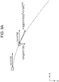
- FIG. 9A is a schematic diagram showing gravity and fall velocity acting when an object is thrown out in the horizontal direction from conveyor 101 if a gravitational acceleration is g and there is no air resistance.
- the horizontal direction is an X axis on which a right hand in the horizontal direction is positive
- the vertical direction is a Z axis on which a downward direction in the vertical direction is positive.
- Vx a velocity of the object thrown out in the horizontal direction from conveyor 101
- Vx in the X axis direction
- Vz V100
- Vz g (X/V100)
- the present disclosure is to solve the conventional problem, and an object thereof is to provide a sorting device that enables three types of resin to be sorted simultaneously.
- a sorting device that sorts a specific material type matter and another material type matter from sorting objects, and includes a conveyor, an identification part, an air blower, an upper rectifying plate, a lower rectifying plate, and a plurality of injectors.
- the conveyor conveys the sorting objects in a placed state in one direction, the sorting objects having the specific material type matter and the other material type matter other than the specific material type matter mixed, and causes the sorting objects to fly at a forefront portion of the conveyor.
- the identification part identifies composition of the specific material type matter placed on the conveyor.
- the air blower generates an airflow in a flying-out direction of the sorting objects.
- the upper rectifying plate is disposed along a flight path of the sorting objects above the flight path.
- the lower rectifying plate is disposed along the flight path obliquely below the forefront portion of the conveyor under the flight path.
- the plurality of injectors are disposed above the flight path so as to be directed to the flight path, and inject pulse air to the specific material type matter flying from the conveyor.
- a sorting device in which at least three nozzle groups that inject pulse air can be installed, and flight variation is suppressed can be realized, and three types of resin can be simultaneously sorted.
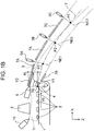
- FIG. 1A is a side view of a sorting device in one exemplary embodiment of the present disclosure.
- the sorting device includes conveyor 1 as one example of a conveyance device, first assist nozzle 6 as one example of a first air blower, identification device 3 as one example of an identification part, first upper rectifying plates 7A, second upper rectifying plate 7C, lower rectifying plate 7B, first nozzle group 5A, second nozzle group 5B, and third nozzle group 5C as one example of a plurality of injectors, and second assist nozzle 10 as one example of a second air blower. Furthermore, the identification device also includes control device 90. Control device 90 controls operations of conveyor 1, first assist nozzle 6, identification device 3, and the plurality of nozzle groups 5A, 5B, 5C, and second assist nozzle 10.
- the sorting device is a sorting device that sorts a specific material type matter and another material type matter from sorting objects in which the specific material type matter and the other material type matter other than the specific material type matter are mixed.
- the first air blower and the second air blower function as one example of an air blower.
- First upper rectifying plates 7A and second upper rectifying plate 7C function as examples of an upper rectifying plate.
- conveyor 1 conveys small resin pieces 2, which are the sorting objects placed on conveyor 1, in one direction (in a right direction in FIG.1A ). Small resin pieces 2 that reach conveyor forefront portion 4 in a conveyance direction of conveyor 1 fly out in a horizontal direction at the same velocity as conveyance velocity V0 of conveyor 1.
- identification device 3 Above a forefront vicinity of conveyor 1 is disposed identification device 3.
- composition of the relevant small resin piece 2 is identified by identification device 3, and at the same time, position information on conveyor 1 is also acquired by identification device 3.
- first assist nozzle 6 as one example of the first air blower that generates first airflow 9.
- the plurality of planar first upper rectifying plates 7A are disposed adjacent to one another along flight path T from a forefront portion of first assist nozzle 6 to a downstream side of flight path T.
- planer lower rectifying plate 7B is disposed along flight path T.
- first upper rectifying plates 7A Between the adjacent plurality of first upper rectifying plates 7A are disposed a plurality of nozzles of first nozzle group 5A as an example of an upstream-side injector, whose blowing-out ports are directed to flight path T.
- a downstream-side end portion of first upper rectifying plate 7A on the downstream side of the plurality of first upper rectifying plates 7A are disposed a plurality of nozzles of second nozzle group 5B as one example of an injector in an intermediate portion, whose blowing-out ports are directed to flight path T.
- planar second upper rectifying plate 7C is disposed along flight path T.
- a downstream-side end portion of second upper rectifying plate 7C are disposed a plurality of nozzles of third nozzle group 5C as one example of a downstream-side injector, whose blowing-out ports are directed to flight path T.
- Small resin pieces 2 shot from flight path T are collected in any of four of first to fourth sections 20A, 20B, 20C, 20D partitioned by type by three partition plates 8 different in height and disposed below flight path T.
- a configuration is such that second assist nozzle 10 as one example of the second air blower is disposed at a position behind first assist nozzle 6 outside flight path T (in FIG. 1A , at the position further behind identification device 3 behind first assist nozzle 6), and that second airflow 11 at a wind velocity equivalent to conveyor conveyance velocity V0 is supplied from a blowing-out port of second assist nozzle 10 to a surface of conveyor 1.
- First airflow 9 and second airflow 11 function as examples of an airflow.
- First assist nozzle 6 above conveyor forefront portion 4 is disposed so that a nozzle forefront of fist assist nozzle 6 is located in the vicinity of a surface of first upper rectifying plate 7A on the upstream side. This disposition allows first airflow 9 supplied from first assist nozzle 6 to flow along the surface of first upper rectifying plate 7A immediately after the blowing-out by Coanda effect, and to gradually spread as it flows downstream.
- second airflow 11 supplied from second assist nozzle 10 flows along the surface of conveyor 1 in the conveyance direction of conveyor 1 at the wind velocity equivalent to conveyor conveyance velocity V0, flows out from conveyor forefront portion 4 toward flight path T of small resin pieces 2, and gradually spreads as it flows downstream.
- wind velocity distribution of a combined airflow of first airflow 9 and second airflow 11 in the Z axis direction at position x in the X axis direction including flight path T is wind velocity distribution of a combined airflow formed by combining, at conveyor forefront portion 4, first airflow 9 from first assist nozzle 6 at conveyor forefront portion 4 and second airflow 11 supplied from second assist nozzle 10.
- first airflow 9 at the wind velocity higher than second airflow 11 at conveyor forefront portion 4 is supplied to the surface vicinity of first upper rectifying plate 7A on the upstream side from first assist nozzle 6, by which first airflow 9 flows along the surface of first upper rectifying plate 7A on the upstream side by the Coanda effect.
- first airflow 9 passes above small resin pieces 2 immediately after the flying-out, and gradually spreads downstream.
- the wind velocity distribution of the combined airflow resulting from combining first airflow 9 and second airflow 11 can increase the wind velocity of the combined airflow along flight path T, and at all positions on flight path T, small resin pieces 2 have the relative velocity 0, and can be substantially prevented from receiving the air resistance.
- small resin pieces 2 of PS among small resin pieces 2 are shot from flight path T by first nozzle group 5A
- small resin pieces 2 of PP among small resin pieces 2 are shot from flight path T by second nozzle group 5B
- only small resin pieces 2 of ABS among small resin pieces 2 are shot from flight path T by third nozzle group 5C.
- small resin pieces 2 shot from flight path T small resin pieces 2 of PS are collected in first section 20A
- small resin pieces 2 of PP are collected in second section 20B
- small resin pieces 2 of ABS are collected in third section 20C
- small resin pieces 2 of the resin of the other types are collected in fourth section 20D.
- This can increase the wind velocity of the combined airflow along flight path T so that small resin pieces 2 as the sorting objects substantially do not receive the air resistance. This substantially prevents small resin pieces 2 from receiving the air resistance regardless of the shapes, the areas, or the weights of small resin pieces 2 even if the flight distance is long. Therefore, the flight variation of small resin pieces 2 can be suppressed, the shooting accuracy is improved, so that only the relevant specific material type can be sorted from the other material types to be collected in the relevant section.
- the times when small resin pieces 2 pass the positions where they receive the pulse air of first nozzle group 5A, second nozzle group 5B, and third nozzle group 5C, respectively are calculated or measured in a passage time acquiring part such as an arithmetic operation part inside control device 90.
- relevant small resin pieces 2 are shot from flight path T by the pulse air, and the shot resin from flight path T is collected by type in any of the four sections of first to fourth sections 20A, 20B, 20C, 20D partitioned by three partition plates 8.
- the wind velocity distribution of the combined airflow from the conveyor surface to the surface of first upper rectifying plate 7A at conveyor forefront portion 4 is made proper distribution described later, which can increase the wind velocity along flight path T so that small resin pieces 2 as the sorting objects substantially do not receive the air resistance.
- the three types of specific material type matters and the other material type matters can be simultaneously sorted with high accuracy from the sorting objects in which the specific material type matters and the other material type matters are mixed.
- a sorting purity and a collection yield of small resin pieces 2 of the desired specific material type can be increased.
- the conveyance velocity of conveyor 1 is defined as V0
- a wind velocity in the vicinity of the conveyor surface at conveyor forefront portion 4 is defined as V1
- a maximum wind velocity in the wind velocity distribution in the Z axis direction from the surface of first upper rectifying plate 7A to the surface of conveyor 1 at conveyor forefront portion 4 is defined as V2
- a shortest distance between the surface of first upper rectifying plate 7A and the surface of conveyor 1 at conveyor forefront portion 4 is defined as H.
- the wind velocity distribution from the conveyor surface at conveyor forefront portion 4 to the surface of first upper rectifying plate 7A is made the proper distribution, by which the wind velocity distribution on flight path T of small resin pieces 2 that matches flight path T of small resin pieces 2, and matches the fall velocity of small resin pieces 2 can be obtained.
- measurement points on flight path T are defined as follows. First, a point of conveyor forefront portion 4 on flight path T is defined as P0. A point where small resin pieces 2 pass the position where they receive the pulse air of first nozzle group 5A on flight path T, that is, an intersection point between flight path T and nozzle extension line NE1 of first nozzle group 5A is defined as P1.
- a point where small resin pieces 2 pass the position where they receive the pulse air of second nozzle group 5B on flight path T, that is, an intersection point between flight path T and nozzle extension line NE2 of second nozzle group 5B is defined as P2.
- a point where small resin pieces 2 pass the position where they receive the pulse air of third nozzle group 5C on flight path T, that is, an intersection point between flight path T and nozzle extension line NE3 of third nozzle group 5C is defined as P3.
- a wind velocity/wind temperature prove made by Tohnic (QA-30) is used.
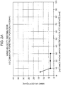
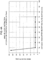
- FIG. 2A is a graph showing the wind velocity distribution in the Z axis direction from the surface of first upper rectifying plate 7A to the surface of conveyor 1 at conveyor forefront portion 4.
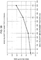
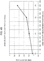
- FIG. 2B is a graph showing wind velocity results at points P0, P1, P2, P3 at this time.
- the wind velocity distribution becomes maximum value V2 at a point of 5mm in the Z axis direction from the surface of first upper rectifying plate 7A.
- FIG. 3A is a graph showing the wind velocity distribution in the Z axis direction from the surface of first upper rectifying plate 7A to the surface of conveyor 1 at conveyor forefront portion 4.
- FIG. 3B is a graph showing wind velocity results at points P0, P1, P2, P3 at this time.
- FIG. 4A is a graph showing the wind velocity distribution in the Z axis direction from the surface of first upper rectifying plate 7A to the surface of conveyor 1 at conveyor forefront portion 4.
- FIG. 4B is a graph showing wind velocity results at points P0, P1, P2, P3 at this time.
- the wind velocity distribution in the Z axis direction (the vertical direction) of the combined airflow from the surface of first upper rectifying plate 7A to the surface of conveyor 1 at conveyor forefront portion 4 has maximum value V2 in the range of less than 10 mm in the Z axis direction (downward of the vertical direction) from the surface of first upper rectifying plate 7A.
- the ratio (V2/V1) obtained by dividing maximum value V2 by wind velocity V1 in the vicinity of the surface of conveyor 1 at conveyor forefront portion 4 is 4 or more, and 12 or less.
- the combined airflow is equal to the wind velocity in the vicinity of the surface of conveyor 1 at conveyor forefront portion 4, the combined airflow spreads as it flows downstream, and the wind velocity of small resin pieces 2 on flight path T matches the increase in the fall velocity. It can be understood that with the foregoing configuration, the proper wind velocity distribution can be realized. Thus, the above-described wind velocity distribution is the proper wind velocity distribution of the combined airflow.
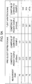
- FIG. 5B is a table in which the comparative example and the example are compared, wherein sorting accuracy in the conditions that result in the best wind velocity distribution as the best conditions of this example is measured, and the relevant sorting accuracy is compared with the sorting accuracy in the conditions when the example is not carried out in the configuration in FIG. 7 as the conditions of the comparative example.
- small resin pieces 2 made of small resin pieces 2 whose material type is PS, small resin pieces 2 whose material type is PP, and small resin pieces 2 whose material type is ABS small resin pieces 2 of PS are shot by first nozzle group 5A, small resin pieces 2 of PP are shot by second nozzle group 5B, and small resin pieces 2 of ABS are shot by third nozzle group 5C.
- the sorting purity and a collection rate when small resin pieces 2 are collected in first to third sections 20A, 20B, 20C partitioned by partition plates 8 are shown.
- the wind velocity distribution along flight path T of small resin pieces 2 increases from about 3m/s to about 3.6 m/s, while under the conditions of the comparative example in which the example is not carried out, the wind velocity distribution decreases from about 3 m/s to 2.4 m/s.
- flight variation 3 ⁇ is kept to be 39 mm or less, while under the conditions of the comparative example in which the example is not carried out, flight variation 3 ⁇ disadvantageously becomes 45 mm or more. From this, it can be said that the configuration in which the wind velocity is increased along flight path T can reduce the flight variation.
- the sorting purity of 99% or more, and the collection rate of 90% or more are assured, while under the conditions of the comparative example in which the example is not carried out, although as to PS, PP, the sorting purity of 99% or more, and the collection rate 75% or more are assured, as for ABS, the sorting purity is 92.3%, and the collection rate is 35.3%.
- the use of the sorting device in the exemplary embodiment of the present disclosure reduces the flight variation and improves the sorting accuracy by increasing the wind velocity along flight path T.
- the conventional sorting device has had the flight variation of resin, which enables at most two nozzle groups that inject pulse air to be installed.
- the wind velocity can be increased along flight path T so that small resin pieces 2 as the sorting objects substantially do not receive air resistance. This almost substantially prevents small resin pieces 2 from receiving the air resistance regardless of the shapes, the areas, the weights of small resin pieces 2 even if the flight distance of small resin pieces 2 becomes long, and the flight variation can be suppressed, so that the shooting accuracy can be improved.
- the wind velocity is increased along flight path T so that small resin pieces 2 as the sorting objects substantially do not receive the air resistance, at least three nozzle groups 5A, 5B, 5C that inject the pulse air can be installed, the sorting device that suppresses the flight variation can be realized, and three types of resins can be simultaneously sorted.
- the sorting device of the present disclosure can increase sorting purity and collection yield of small pieces of desired specific material types even when small pieces as sorting objects made of three material types are sorted individually in a series of flight path, and can be applied to resource circulation of materials as a sorting device that recycles small pieces of specific material types included in waste home electric appliances or general wastes.
Landscapes
- Engineering & Computer Science (AREA)
- Multimedia (AREA)
- Sorting Of Articles (AREA)
Claims (3)
- Sortiervorrichtung, die ein spezifisches Material vom Feststofftyp von einem anderen Material vom Feststofftyp von Sortierobjekten (2) sortiert, wobei die Sortiervorrichtung Folgendes aufweist:einen Förderer (1), der die Sortierobjekte (2) in einem platzierten Zustand in einer Richtung fördert, wobei die Sortierobjekte (2) das spezifische Material vom Feststofftyp und das sich vom spezifischen Material vom Feststofftyp unterscheidende andere Material vom Feststofftyp gemischt aufweist und bewirkt, dass die Sortierobjekte (2) an einem vorderen Teil des Förderers (1) fliegen;ein Identifikationsteil (3), das die Zusammensetzung des auf dem Förderer (1) platzierten spezifischen Materials vom Feststofftyp identifiziert;ein Luftgebläse (6, 10), das einen Luftstrom in einer Ausflugrichtung der Sortierobjekte (2) erzeugt;eine obere Gleichrichtplatte (7A), die entlang einer Flugbahn (T) der Sortierobjekte (2) oberhalb der Flugbahn angeordnet ist;eine untere Gleichrichtplatte (7B), die entlang einer Flugbahn (T) schräg unterhalb des vorderen Teils des Förderers (1) unterhalb der Flugbahn (T) angeordnet ist;mehrere Injektoren (5A, 5B, 5C), die oberhalb der Flugbahn (T) angeordnet sind, um auf die Flugbahn (T) gerichtet zu werden und Impulsluft an das vom Förderer (1) fliegende spezifische Material vom Feststofftyp einzuspritzen,dadurch gekennzeichnet, dass eine Windgeschwindigkeitsverteilung in einer senkrechten Richtung des Luftstroms von einer Oberfläche der oberen Gleichrichtplatte (7A) zu einer Oberfläche des Förderers (1) am vorderen Teil des Förderers (1) einen Höchstwert in einem Bereich von weniger als 10 mm nach unten in der senkrechten Richtung von der Oberfläche der oberen Gleichrichtplatte (7A) aufweist, wobei ein durch Division des Höchstwertes mit einer Windgeschwindigkeit in der Nähe der Oberfläche des Förderers erhaltenes Verhältnis 4 oder mehr und 12 oder weniger beträgt, und in einem anderen Bereich als dem Bereich von weniger als 10 mm der Luftstrom eine Windgeschwindigkeit hat, die gleich der Windgeschwindigkeit in der Nähe der Oberfläche des Förderers (1) ist.
- Sortiervorrichtung nach Anspruch 1, wobei angenommen, dass die Windgeschwindigkeit in der Nähe der Oberfläche des Förderers (1) als V1 (mm/s) definiert ist,
der Höchstwert der Windgeschwindigkeitsverteilung von der Oberfläche des Förderers (1) zur Oberfläche der oberen Gleichrichtplatte (7A) am vorderen Teil des Förderers (1) als V2 (mm/s) definiert ist, und
ein kürzester Abstand zwischen der Oberfläche des Förderers (1) und der Oberfläche der oberen Gleichrichtungsplatte (7A) am vorderen Teil des Förderers (1) als H (mm) definiert ist,
- Sortiervorrichtung nach Anspruch 1 oder Anspruch 2, wobei
das Luftgebläse aus einem ersten Luftgebläse (6) besteht, das so oberhalb des vorderen Teils des Förderers (1) angeordnet ist, dass sich eine Düsenvorderseite in der Nähe der Oberfläche der oberen Gleichrichtplatte (7A) befindet um einen ersten Luftstrom (9) zu liefern, und
einem zweiten Luftgebläse (10), das außerhalb der Flugbahn (T) an einer Stelle hinter dem ersten Luftgebläse (6) angeordnet ist, um von einer Ausblasöffnung einen zweiten Luftstrom (11) bei einer Windgeschwindigkeit zu liefern, die einer Fördergeschwindigkeit des Förderers in Richtung zur Oberfläche des Förderers (1) entspricht, und
die Windgeschwindigkeitsverteilung in der senkrechten Richtung des Luftstroms die Windgeschwindigkeitsverteilung in der senkrechten Richtung eines durch Kombinieren des ersten Luftstroms (9) und des zweiten (11) Luftstroms erhaltenen Luftstroms ist.
Applications Claiming Priority (1)
| Application Number | Priority Date | Filing Date | Title |
|---|---|---|---|
| JP2015099349A JP6283958B2 (ja) | 2015-05-14 | 2015-05-14 | 選別装置 |
Publications (2)
| Publication Number | Publication Date |
|---|---|
| EP3093076A1 EP3093076A1 (de) | 2016-11-16 |
| EP3093076B1 true EP3093076B1 (de) | 2017-10-25 |
Family
ID=55808993
Family Applications (1)
| Application Number | Title | Priority Date | Filing Date |
|---|---|---|---|
| EP16166693.8A Active EP3093076B1 (de) | 2015-05-14 | 2016-04-22 | Sortiervorrichtung |
Country Status (4)
| Country | Link |
|---|---|
| US (1) | US9808835B2 (de) |
| EP (1) | EP3093076B1 (de) |
| JP (1) | JP6283958B2 (de) |
| CN (1) | CN106140653B (de) |
Families Citing this family (11)
| Publication number | Priority date | Publication date | Assignee | Title |
|---|---|---|---|---|
| JP2017164722A (ja) * | 2016-03-18 | 2017-09-21 | 株式会社イシダ | 振分装置 |
| GB201613068D0 (en) * | 2016-07-28 | 2016-09-14 | Univ Of Manchester The | Transfer of granular materials |
| JP6778874B2 (ja) * | 2017-01-10 | 2020-11-04 | パナソニックIpマネジメント株式会社 | 選別装置 |
| JP6785475B2 (ja) | 2017-11-15 | 2020-11-18 | パナソニックIpマネジメント株式会社 | 選別装置 |
| AT520798B1 (de) * | 2018-01-10 | 2024-08-15 | Insort Gmbh | Vorrichtung zum Ausschleusen von Schlechtprodukten aus einem Produktstrom |
| JP6931805B2 (ja) | 2018-11-27 | 2021-09-08 | パナソニックIpマネジメント株式会社 | 選別装置 |
| CN112403942A (zh) * | 2020-12-08 | 2021-02-26 | 合肥泰禾智能科技集团股份有限公司 | 一种实现多类分选的色选机 |
| IT202200016842A1 (it) * | 2022-08-05 | 2024-02-05 | Pal S R L | Macchina e procedimento di separazione materiali a base di legno da altri materiali |
| KR102610194B1 (ko) * | 2023-10-28 | 2023-12-05 | (주)대주개발 | 폐기물처리 및 순환골재생산 시스템 |
| CN118594975A (zh) * | 2023-12-20 | 2024-09-06 | 北京霍里思特科技有限公司 | 物块分选系统的控制方法及物块分选系统 |
| EP4635640A1 (de) * | 2024-04-19 | 2025-10-22 | Okimation Inc. | Pelletsortierverfahren und -vorrichtung und pelletströmungskanal dafür |
Family Cites Families (25)
| Publication number | Priority date | Publication date | Assignee | Title |
|---|---|---|---|---|
| CA1242260A (en) | 1986-04-24 | 1988-09-20 | Leonard Kelly | Multisorting method and apparatus |
| US5297667A (en) * | 1992-11-12 | 1994-03-29 | Simco/Ramic Corporation | System for stabilizing articles on conveyors |
| DE29604552U1 (de) * | 1995-05-05 | 1996-05-23 | Trützschler GmbH & Co KG, 41199 Mönchengladbach | Vorrichtung in einer Spinnereivorbereitungseinrichtung (Putzerei) zum Erkennen und Ausscheiden von Fremdstoffen, z.B. Gewebestücke, Bänder, Schnüre, Folienstücke, in bzw. aus Fasergut |
| JP3806163B2 (ja) | 1995-09-22 | 2006-08-09 | 三菱重工業株式会社 | 廃プラスチックの材質識別装置 |
| US6003681A (en) * | 1996-06-03 | 1999-12-21 | Src Vision, Inc. | Off-belt stabilizing system for light-weight articles |
| US5862919A (en) | 1996-10-10 | 1999-01-26 | Src Vision, Inc. | High throughput sorting system |
| WO2000058035A1 (en) | 1999-03-29 | 2000-10-05 | Src Vision, Inc. | Multi-band spectral sorting system for light-weight articles |
| US6374998B1 (en) * | 1999-04-29 | 2002-04-23 | Advanced Sorting Technologies Llc | “Acceleration conveyor” |
| JP2001327923A (ja) | 2000-05-24 | 2001-11-27 | Yanmar Diesel Engine Co Ltd | 風選別装置 |
| US8857621B2 (en) * | 2001-10-02 | 2014-10-14 | Emerging Acquisitions, Llc | De-inking screen with air knife |
| JP3647799B2 (ja) | 2001-12-03 | 2005-05-18 | 株式会社御池鐵工所 | 使用済みボトルの色別・材質別選別装置 |
| JP4023190B2 (ja) | 2002-03-26 | 2007-12-19 | 株式会社Ihi | 光学式材質選別装置 |
| US20040245156A1 (en) * | 2003-06-06 | 2004-12-09 | Gaddis Paul G. | Sorting system for sheeted material |
| US7326871B2 (en) * | 2004-08-18 | 2008-02-05 | Mss, Inc. | Sorting system using narrow-band electromagnetic radiation |
| US7775370B2 (en) | 2005-03-21 | 2010-08-17 | Utah State University | Particle sorting by fluidic vectoring |
| US7584856B2 (en) * | 2006-11-03 | 2009-09-08 | Emerging Acquisitions, Llc | Air separation of recyclable material |
| DE102009007481A1 (de) * | 2009-01-30 | 2010-09-02 | Fraunhofer-Gesellschaft zur Förderung der angewandten Forschung e.V. | Fördersystem zum Transport von Materialien, insbesondere von Schüttgut |
| JP5528014B2 (ja) * | 2009-06-08 | 2014-06-25 | ダイオーエンジニアリング株式会社 | プラスチック選別装置 |
| JP5496367B2 (ja) * | 2011-12-15 | 2014-05-21 | パナソニック株式会社 | 選別装置、選別方法 |
| JP6341630B2 (ja) | 2013-03-27 | 2018-06-13 | 国立研究開発法人産業技術総合研究所 | 選別装置 |
| US9381546B2 (en) * | 2013-04-25 | 2016-07-05 | Panasonic Intellectual Property Management Co., Ltd. | Apparatus and method for separating material |
| CN204365593U (zh) * | 2014-11-20 | 2015-06-03 | 四川克莱迪商贸有限责任公司 | 花生仁筛选机 |
| CN204470129U (zh) * | 2014-12-15 | 2015-07-15 | 北国鲜米坊(天津)食品销售连锁有限公司 | 大豆色选机 |
| CN104525503A (zh) * | 2014-12-16 | 2015-04-22 | 核工业理化工程研究院华核新技术开发公司 | 防水型色选机 |
| JP6217985B2 (ja) * | 2014-12-22 | 2017-10-25 | パナソニックIpマネジメント株式会社 | 選別装置 |
-
2015
- 2015-05-14 JP JP2015099349A patent/JP6283958B2/ja active Active
-
2016
- 2016-04-15 US US15/099,594 patent/US9808835B2/en active Active
- 2016-04-22 EP EP16166693.8A patent/EP3093076B1/de active Active
- 2016-05-09 CN CN201610301190.XA patent/CN106140653B/zh active Active
Non-Patent Citations (1)
| Title |
|---|
| None * |
Also Published As
| Publication number | Publication date |
|---|---|
| US20160332200A1 (en) | 2016-11-17 |
| JP2016215085A (ja) | 2016-12-22 |
| US9808835B2 (en) | 2017-11-07 |
| EP3093076A1 (de) | 2016-11-16 |
| CN106140653B (zh) | 2018-08-28 |
| JP6283958B2 (ja) | 2018-02-28 |
| CN106140653A (zh) | 2016-11-23 |
Similar Documents
| Publication | Publication Date | Title |
|---|---|---|
| EP3093076B1 (de) | Sortiervorrichtung | |
| JP6217985B2 (ja) | 選別装置 | |
| JP5496367B2 (ja) | 選別装置、選別方法 | |
| JP5873989B2 (ja) | 物質の選別装置、選別方法 | |
| US8286800B2 (en) | Separation method and separation apparatus | |
| EP2808096A1 (de) | Trennvorrichtung und Trennverfahren | |
| EP3659720B1 (de) | Sortiervorrichtung | |
| WO2023280302A1 (zh) | 一种基于分级阵列式智能分选进行矿石预选的方法及系统 | |
| CN118594975A (zh) | 物块分选系统的控制方法及物块分选系统 | |
| WO2013149293A1 (en) | Separating mined material | |
| JP2011173049A (ja) | 分別方法、および、分別装置 | |
| CN113787025A (zh) | 一种高速分拣设备 | |
| JP6778874B2 (ja) | 選別装置 | |
| KR102818430B1 (ko) | 광학선별기를 이용한 재활용 폐기물의 선별 방법 및 그 장치 | |
| EP3563939A1 (de) | Pneumatisches verfahren zur trennung mineralischer rohmaterialien | |
| Kasiemkhan | Sensor based optimisation of eddy current separation |
Legal Events
| Date | Code | Title | Description |
|---|---|---|---|
| PUAI | Public reference made under article 153(3) epc to a published international application that has entered the european phase |
Free format text: ORIGINAL CODE: 0009012 |
|
| AK | Designated contracting states |
Kind code of ref document: A1 Designated state(s): AL AT BE BG CH CY CZ DE DK EE ES FI FR GB GR HR HU IE IS IT LI LT LU LV MC MK MT NL NO PL PT RO RS SE SI SK SM TR |
|
| AX | Request for extension of the european patent |
Extension state: BA ME |
|
| 17P | Request for examination filed |
Effective date: 20161230 |
|
| RBV | Designated contracting states (corrected) |
Designated state(s): AL AT BE BG CH CY CZ DE DK EE ES FI FR GB GR HR HU IE IS IT LI LT LU LV MC MK MT NL NO PL PT RO RS SE SI SK SM TR |
|
| GRAP | Despatch of communication of intention to grant a patent |
Free format text: ORIGINAL CODE: EPIDOSNIGR1 |
|
| INTG | Intention to grant announced |
Effective date: 20170728 |
|
| GRAS | Grant fee paid |
Free format text: ORIGINAL CODE: EPIDOSNIGR3 |
|
| GRAA | (expected) grant |
Free format text: ORIGINAL CODE: 0009210 |
|
| AK | Designated contracting states |
Kind code of ref document: B1 Designated state(s): AL AT BE BG CH CY CZ DE DK EE ES FI FR GB GR HR HU IE IS IT LI LT LU LV MC MK MT NL NO PL PT RO RS SE SI SK SM TR |
|
| REG | Reference to a national code |
Ref country code: GB Ref legal event code: FG4D |
|
| REG | Reference to a national code |
Ref country code: CH Ref legal event code: EP |
|
| REG | Reference to a national code |
Ref country code: AT Ref legal event code: REF Ref document number: 939442 Country of ref document: AT Kind code of ref document: T Effective date: 20171115 |
|
| REG | Reference to a national code |
Ref country code: IE Ref legal event code: FG4D |
|
| REG | Reference to a national code |
Ref country code: DE Ref legal event code: R096 Ref document number: 602016000628 Country of ref document: DE |
|
| REG | Reference to a national code |
Ref country code: NL Ref legal event code: MP Effective date: 20171025 |
|
| REG | Reference to a national code |
Ref country code: LT Ref legal event code: MG4D |
|
| REG | Reference to a national code |
Ref country code: AT Ref legal event code: MK05 Ref document number: 939442 Country of ref document: AT Kind code of ref document: T Effective date: 20171025 |
|
| PG25 | Lapsed in a contracting state [announced via postgrant information from national office to epo] |
Ref country code: NL Free format text: LAPSE BECAUSE OF FAILURE TO SUBMIT A TRANSLATION OF THE DESCRIPTION OR TO PAY THE FEE WITHIN THE PRESCRIBED TIME-LIMIT Effective date: 20171025 |
|
| REG | Reference to a national code |
Ref country code: FR Ref legal event code: PLFP Year of fee payment: 3 |
|
| PG25 | Lapsed in a contracting state [announced via postgrant information from national office to epo] |
Ref country code: NO Free format text: LAPSE BECAUSE OF FAILURE TO SUBMIT A TRANSLATION OF THE DESCRIPTION OR TO PAY THE FEE WITHIN THE PRESCRIBED TIME-LIMIT Effective date: 20180125 Ref country code: LT Free format text: LAPSE BECAUSE OF FAILURE TO SUBMIT A TRANSLATION OF THE DESCRIPTION OR TO PAY THE FEE WITHIN THE PRESCRIBED TIME-LIMIT Effective date: 20171025 Ref country code: ES Free format text: LAPSE BECAUSE OF FAILURE TO SUBMIT A TRANSLATION OF THE DESCRIPTION OR TO PAY THE FEE WITHIN THE PRESCRIBED TIME-LIMIT Effective date: 20171025 Ref country code: FI Free format text: LAPSE BECAUSE OF FAILURE TO SUBMIT A TRANSLATION OF THE DESCRIPTION OR TO PAY THE FEE WITHIN THE PRESCRIBED TIME-LIMIT Effective date: 20171025 Ref country code: SE Free format text: LAPSE BECAUSE OF FAILURE TO SUBMIT A TRANSLATION OF THE DESCRIPTION OR TO PAY THE FEE WITHIN THE PRESCRIBED TIME-LIMIT Effective date: 20171025 |
|
| PG25 | Lapsed in a contracting state [announced via postgrant information from national office to epo] |
Ref country code: RS Free format text: LAPSE BECAUSE OF FAILURE TO SUBMIT A TRANSLATION OF THE DESCRIPTION OR TO PAY THE FEE WITHIN THE PRESCRIBED TIME-LIMIT Effective date: 20171025 Ref country code: LV Free format text: LAPSE BECAUSE OF FAILURE TO SUBMIT A TRANSLATION OF THE DESCRIPTION OR TO PAY THE FEE WITHIN THE PRESCRIBED TIME-LIMIT Effective date: 20171025 Ref country code: IS Free format text: LAPSE BECAUSE OF FAILURE TO SUBMIT A TRANSLATION OF THE DESCRIPTION OR TO PAY THE FEE WITHIN THE PRESCRIBED TIME-LIMIT Effective date: 20180225 Ref country code: BG Free format text: LAPSE BECAUSE OF FAILURE TO SUBMIT A TRANSLATION OF THE DESCRIPTION OR TO PAY THE FEE WITHIN THE PRESCRIBED TIME-LIMIT Effective date: 20180125 Ref country code: GR Free format text: LAPSE BECAUSE OF FAILURE TO SUBMIT A TRANSLATION OF THE DESCRIPTION OR TO PAY THE FEE WITHIN THE PRESCRIBED TIME-LIMIT Effective date: 20180126 Ref country code: AT Free format text: LAPSE BECAUSE OF FAILURE TO SUBMIT A TRANSLATION OF THE DESCRIPTION OR TO PAY THE FEE WITHIN THE PRESCRIBED TIME-LIMIT Effective date: 20171025 Ref country code: HR Free format text: LAPSE BECAUSE OF FAILURE TO SUBMIT A TRANSLATION OF THE DESCRIPTION OR TO PAY THE FEE WITHIN THE PRESCRIBED TIME-LIMIT Effective date: 20171025 |
|
| REG | Reference to a national code |
Ref country code: DE Ref legal event code: R097 Ref document number: 602016000628 Country of ref document: DE |
|
| PG25 | Lapsed in a contracting state [announced via postgrant information from national office to epo] |
Ref country code: SK Free format text: LAPSE BECAUSE OF FAILURE TO SUBMIT A TRANSLATION OF THE DESCRIPTION OR TO PAY THE FEE WITHIN THE PRESCRIBED TIME-LIMIT Effective date: 20171025 Ref country code: CZ Free format text: LAPSE BECAUSE OF FAILURE TO SUBMIT A TRANSLATION OF THE DESCRIPTION OR TO PAY THE FEE WITHIN THE PRESCRIBED TIME-LIMIT Effective date: 20171025 Ref country code: EE Free format text: LAPSE BECAUSE OF FAILURE TO SUBMIT A TRANSLATION OF THE DESCRIPTION OR TO PAY THE FEE WITHIN THE PRESCRIBED TIME-LIMIT Effective date: 20171025 Ref country code: CY Free format text: LAPSE BECAUSE OF FAILURE TO SUBMIT A TRANSLATION OF THE DESCRIPTION OR TO PAY THE FEE WITHIN THE PRESCRIBED TIME-LIMIT Effective date: 20171025 Ref country code: DK Free format text: LAPSE BECAUSE OF FAILURE TO SUBMIT A TRANSLATION OF THE DESCRIPTION OR TO PAY THE FEE WITHIN THE PRESCRIBED TIME-LIMIT Effective date: 20171025 |
|
| PG25 | Lapsed in a contracting state [announced via postgrant information from national office to epo] |
Ref country code: IT Free format text: LAPSE BECAUSE OF FAILURE TO SUBMIT A TRANSLATION OF THE DESCRIPTION OR TO PAY THE FEE WITHIN THE PRESCRIBED TIME-LIMIT Effective date: 20171025 Ref country code: SM Free format text: LAPSE BECAUSE OF FAILURE TO SUBMIT A TRANSLATION OF THE DESCRIPTION OR TO PAY THE FEE WITHIN THE PRESCRIBED TIME-LIMIT Effective date: 20171025 Ref country code: PL Free format text: LAPSE BECAUSE OF FAILURE TO SUBMIT A TRANSLATION OF THE DESCRIPTION OR TO PAY THE FEE WITHIN THE PRESCRIBED TIME-LIMIT Effective date: 20171025 |
|
| PLBE | No opposition filed within time limit |
Free format text: ORIGINAL CODE: 0009261 |
|
| STAA | Information on the status of an ep patent application or granted ep patent |
Free format text: STATUS: NO OPPOSITION FILED WITHIN TIME LIMIT |
|
| 26N | No opposition filed |
Effective date: 20180726 |
|
| PG25 | Lapsed in a contracting state [announced via postgrant information from national office to epo] |
Ref country code: MC Free format text: LAPSE BECAUSE OF FAILURE TO SUBMIT A TRANSLATION OF THE DESCRIPTION OR TO PAY THE FEE WITHIN THE PRESCRIBED TIME-LIMIT Effective date: 20171025 Ref country code: SI Free format text: LAPSE BECAUSE OF FAILURE TO SUBMIT A TRANSLATION OF THE DESCRIPTION OR TO PAY THE FEE WITHIN THE PRESCRIBED TIME-LIMIT Effective date: 20171025 |
|
| REG | Reference to a national code |
Ref country code: BE Ref legal event code: MM Effective date: 20180430 |
|
| REG | Reference to a national code |
Ref country code: IE Ref legal event code: MM4A |
|
| PG25 | Lapsed in a contracting state [announced via postgrant information from national office to epo] |
Ref country code: LU Free format text: LAPSE BECAUSE OF NON-PAYMENT OF DUE FEES Effective date: 20180422 |
|
| PG25 | Lapsed in a contracting state [announced via postgrant information from national office to epo] |
Ref country code: BE Free format text: LAPSE BECAUSE OF NON-PAYMENT OF DUE FEES Effective date: 20180430 |
|
| PG25 | Lapsed in a contracting state [announced via postgrant information from national office to epo] |
Ref country code: IE Free format text: LAPSE BECAUSE OF NON-PAYMENT OF DUE FEES Effective date: 20180422 |
|
| REG | Reference to a national code |
Ref country code: CH Ref legal event code: PL |
|
| PG25 | Lapsed in a contracting state [announced via postgrant information from national office to epo] |
Ref country code: CH Free format text: LAPSE BECAUSE OF NON-PAYMENT OF DUE FEES Effective date: 20190430 Ref country code: LI Free format text: LAPSE BECAUSE OF NON-PAYMENT OF DUE FEES Effective date: 20190430 Ref country code: MT Free format text: LAPSE BECAUSE OF NON-PAYMENT OF DUE FEES Effective date: 20180422 |
|
| PG25 | Lapsed in a contracting state [announced via postgrant information from national office to epo] |
Ref country code: TR Free format text: LAPSE BECAUSE OF FAILURE TO SUBMIT A TRANSLATION OF THE DESCRIPTION OR TO PAY THE FEE WITHIN THE PRESCRIBED TIME-LIMIT Effective date: 20171025 |
|
| PG25 | Lapsed in a contracting state [announced via postgrant information from national office to epo] |
Ref country code: PT Free format text: LAPSE BECAUSE OF FAILURE TO SUBMIT A TRANSLATION OF THE DESCRIPTION OR TO PAY THE FEE WITHIN THE PRESCRIBED TIME-LIMIT Effective date: 20171025 |
|
| PG25 | Lapsed in a contracting state [announced via postgrant information from national office to epo] |
Ref country code: HU Free format text: LAPSE BECAUSE OF FAILURE TO SUBMIT A TRANSLATION OF THE DESCRIPTION OR TO PAY THE FEE WITHIN THE PRESCRIBED TIME-LIMIT; INVALID AB INITIO Effective date: 20160422 Ref country code: MK Free format text: LAPSE BECAUSE OF NON-PAYMENT OF DUE FEES Effective date: 20171025 Ref country code: RO Free format text: LAPSE BECAUSE OF FAILURE TO SUBMIT A TRANSLATION OF THE DESCRIPTION OR TO PAY THE FEE WITHIN THE PRESCRIBED TIME-LIMIT Effective date: 20171025 |
|
| PG25 | Lapsed in a contracting state [announced via postgrant information from national office to epo] |
Ref country code: AL Free format text: LAPSE BECAUSE OF FAILURE TO SUBMIT A TRANSLATION OF THE DESCRIPTION OR TO PAY THE FEE WITHIN THE PRESCRIBED TIME-LIMIT Effective date: 20171025 |
|
| PGFP | Annual fee paid to national office [announced via postgrant information from national office to epo] |
Ref country code: DE Payment date: 20250422 Year of fee payment: 10 |
|
| PGFP | Annual fee paid to national office [announced via postgrant information from national office to epo] |
Ref country code: GB Payment date: 20250423 Year of fee payment: 10 |
|
| PGFP | Annual fee paid to national office [announced via postgrant information from national office to epo] |
Ref country code: FR Payment date: 20250425 Year of fee payment: 10 |