EP3659347B1 - Kraftfahrzeugdachantenne mit mindestens einem kraftfahrzeugaussenmikrofon, verfahren zum betreiben derselben und kraftfahrzeug mit mindestens einem kraftfahrzeugaussenmikrofon - Google Patents
Kraftfahrzeugdachantenne mit mindestens einem kraftfahrzeugaussenmikrofon, verfahren zum betreiben derselben und kraftfahrzeug mit mindestens einem kraftfahrzeugaussenmikrofon Download PDFInfo
- Publication number
- EP3659347B1 EP3659347B1 EP19723043.6A EP19723043A EP3659347B1 EP 3659347 B1 EP3659347 B1 EP 3659347B1 EP 19723043 A EP19723043 A EP 19723043A EP 3659347 B1 EP3659347 B1 EP 3659347B1
- Authority
- EP
- European Patent Office
- Prior art keywords
- motor vehicle
- microphone
- opening
- antenna
- external microphone
- Prior art date
- Legal status (The legal status is an assumption and is not a legal conclusion. Google has not performed a legal analysis and makes no representation as to the accuracy of the status listed.)
- Active
Links
Images

Classifications
-
- H—ELECTRICITY
- H01—ELECTRIC ELEMENTS
- H01Q—ANTENNAS, i.e. RADIO AERIALS
- H01Q1/00—Details of, or arrangements associated with, antennas
- H01Q1/27—Adaptation for use in or on movable bodies
- H01Q1/32—Adaptation for use in or on road or rail vehicles
- H01Q1/325—Adaptation for use in or on road or rail vehicles characterised by the location of the antenna on the vehicle
- H01Q1/3275—Adaptation for use in or on road or rail vehicles characterised by the location of the antenna on the vehicle mounted on a horizontal surface of the vehicle, e.g. on roof, hood, trunk
-
- B—PERFORMING OPERATIONS; TRANSPORTING
- B60—VEHICLES IN GENERAL
- B60R—VEHICLES, VEHICLE FITTINGS, OR VEHICLE PARTS, NOT OTHERWISE PROVIDED FOR
- B60R11/00—Arrangements for holding or mounting articles, not otherwise provided for
- B60R11/02—Arrangements for holding or mounting articles, not otherwise provided for for radio sets, television sets, telephones, or the like; Arrangement of controls thereof
- B60R11/0247—Arrangements for holding or mounting articles, not otherwise provided for for radio sets, television sets, telephones, or the like; Arrangement of controls thereof for microphones or earphones
-
- H—ELECTRICITY
- H04—ELECTRIC COMMUNICATION TECHNIQUE
- H04R—LOUDSPEAKERS, MICROPHONES, GRAMOPHONE PICK-UPS OR LIKE ACOUSTIC ELECTROMECHANICAL TRANSDUCERS; ELECTRIC HEARING AIDS; PUBLIC ADDRESS SYSTEMS
- H04R1/00—Details of transducers, loudspeakers or microphones
- H04R1/08—Mouthpieces; Microphones; Attachments therefor
- H04R1/083—Special constructions of mouthpieces
- H04R1/086—Protective screens, e.g. all weather or wind screens
-
- B—PERFORMING OPERATIONS; TRANSPORTING
- B60—VEHICLES IN GENERAL
- B60R—VEHICLES, VEHICLE FITTINGS, OR VEHICLE PARTS, NOT OTHERWISE PROVIDED FOR
- B60R11/00—Arrangements for holding or mounting articles, not otherwise provided for
- B60R2011/0001—Arrangements for holding or mounting articles, not otherwise provided for characterised by position
- B60R2011/004—Arrangements for holding or mounting articles, not otherwise provided for characterised by position outside the vehicle
-
- H—ELECTRICITY
- H04—ELECTRIC COMMUNICATION TECHNIQUE
- H04R—LOUDSPEAKERS, MICROPHONES, GRAMOPHONE PICK-UPS OR LIKE ACOUSTIC ELECTROMECHANICAL TRANSDUCERS; ELECTRIC HEARING AIDS; PUBLIC ADDRESS SYSTEMS
- H04R2499/00—Aspects covered by H04R or H04S not otherwise provided for in their subgroups
- H04R2499/10—General applications
- H04R2499/13—Acoustic transducers and sound field adaptation in vehicles
Definitions
- the present invention relates to a motor vehicle roof antenna with at least one motor vehicle exterior microphone with at least one microphone unit which has a microphone capsule arranged in a microphone housing, the microphone housing having at least one microphone opening, whereby an acoustic channel is formed between the at least one microphone opening and the microphone capsule, the motor vehicle exterior microphone comprises a switching device which is designed to release the at least one microphone opening in an activated state of the motor vehicle exterior microphone and to close it in a deactivated state of the motor vehicle exterior microphone. It also relates to a motor vehicle with at least one motor vehicle exterior microphone. Finally, the invention relates to a method for operating a motor vehicle roof antenna.
- a motor vehicle exterior microphone is known, the microphone opening can be protected.
- a flap can be pivoted or moved.
- the detection device can be an acoustic sensor device include, with which acoustic signals from emergency vehicles can be detected.
- a microphone assembly for a vehicle hands-free device comprising a microphone unit which can be reversibly moved between a retracted and an extended position.
- the microphone assembly is arranged in the vehicle interior, in particular in an indentation in a headliner.
- the system comprises a microphone which is arranged on an external structure of the vehicle and is used to receive a voice input.
- two microphones are arranged in a motor vehicle emblem.
- two microphones are integrated in the rear lights of the motor vehicle.
- the DE 10 2014 225 397 A1 relates to the detection of an emergency vehicle with a digital image sensor by a vehicle.
- a microphone which is arranged outside the vehicle, is used to identify the ambulance.
- the motor vehicle exterior microphones known from the prior art, it is often not possible to ensure a sufficient reception quality to enable voice operability of a motor vehicle from outside.
- the better the voice recognition the more different the voice commands of a user to be implemented by the motor vehicle can be, for example opening the trunk, lights on, unlocking the motor vehicle, etc.
- the voice recognition should be enabled as far as possible in a 360 ° environment around the motor vehicle.
- the object of the present invention is therefore to provide improved voice operability of a motor vehicle from the outside.
- a motor vehicle roof antenna with the features of claim 1 a motor vehicle with at least one motor vehicle exterior microphone according to claim 7 and by a method for operating a motor vehicle roof antenna with the features of claim 11.
- the present invention is based on the knowledge that a motor vehicle external microphone must be arranged accordingly in the outside area of a motor vehicle in order to detect voice commands from the person operating the voice. Since microphones are pressure receivers, they must have acoustic openings in order to be able to receive the sound signals. If the openings are closed, they are protected against dust, dirt, water, snow and the like, but their reception quality is significantly reduced as a result. If the openings are kept open permanently, there is a risk of contamination from dust, dirt, water, snow and the like. Especially in vehicles driving in the rain or if they are in a car wash, the microphones would be exposed to significant environmental influences, would no longer correspond to their actual specification after soiling and the beamforming algorithm and thus the speech recognition would be impaired.
- the invention is further based on the knowledge that voice operability from the outside is essentially required when the motor vehicle is stationary, whereas when the motor vehicle is moving, operation can be carried out by means of voice commands in the interior of the motor vehicle using interior microphones.
- voice commands in the interior of the motor vehicle using interior microphones.
- the openings of the microphones are only released when a motor vehicle is at a standstill, whereas they are closed to protect the microphones in the moving motor vehicle.
- excellent voice operability can be provided when the motor vehicle is at a standstill; on the other hand, the microphones are reliably protected from dirt and the like in the phase in which they are not needed.
- a motor vehicle roof antenna according to the invention therefore also has a switching device which is designed to release the at least one microphone opening in an activated state of the motor vehicle exterior microphone and to close it in a deactivated state of the motor vehicle exterior microphone.
- the motor vehicle exterior microphone thus provides excellent reception quality for sound detection when the motor vehicle is stationary, whereas the at least one microphone opening is reliably prevented from being clogged by dirt, dust, water and the like while the motor vehicle is in motion.
- the motor vehicle roof antenna comprises a base body for mounting on a vehicle roof and an antenna body coupled to it, with at least one element of the base body or the antenna body, preferably the antenna body itself, being movable by means of the switching device.
- the microphone opening of at least one microphone unit can accordingly be opened or closed in order to put the motor vehicle exterior microphone into the activated or deactivated state.
- a preferred embodiment is characterized in that the switching device comprises a servomotor as an adjusting device in order to switch the motor vehicle exterior microphone from the deactivated state to the activated state or vice versa.
- the switching device comprises a servomotor as an adjusting device in order to switch the motor vehicle exterior microphone from the deactivated state to the activated state or vice versa.
- the motor vehicle exterior microphone can be switched from the activated to the deactivated state or vice versa in a particularly reliable manner.
- the motor vehicle external microphone can be kept in the respective desired state without any further energy requirement, that is to say without current.
- the switching device can comprise at least one electromagnet device as an adjusting device and a control device for the electromagnet device, the electromagnet device comprising a first and a second element, the first element being movably mounted with respect to the second element, and one of the two elements being stationary with it the microphone opening is coupled, wherein the control device is designed to control the electromagnetic device in such a way that the first and the second element attract in one state and / or repel in another state or at least not attract in order to close and release the at least one microphone opening or the other way around.
- the use of an electromagnetic device provides a particularly inexpensive possibility of switching the motor vehicle exterior microphone from the deactivated state to the activated state or vice versa.
- the switching device can comprise at least one spring device which is arranged in such a way that it counteracts the adjusting device. If the respective adjustment device is accordingly designed in such a way that the motor vehicle exterior microphone is put into the activated state, the motor vehicle exterior microphone is reliably held in the deactivated state by means of the spring device without any further energy requirement.
- the spring device is accordingly preferably tensioned, so that in the deactivated state of the motor vehicle exterior microphone it is in a, by contrast, more relaxed state.
- the switching device is preferably designed to move the antenna body relative to the base body, so that at least one opening, preferably a circumferential gap, in particular a circumferential gap with a width between 1 and 3 mm is created between the base body and the antenna body.
- Each microphone opening can be assigned a separate opening or a circumferential gap can be assigned to all microphone openings. In this way, the microphone opening of a large number of microphone units can be released by a single movement of the antenna body relative to the base body.
- a stroke of between 1 and 3 mm is sufficient to generate a sufficiently wide acoustic channel to ensure a high quality of reception of speech signals.
- the at least one microphone opening preferably protrudes into the opening between the base body and the antenna body, the microphone capsule being arranged above the opening when the motor vehicle external microphone is installed, the microphone housing preferably being watertight. This ensures that in a water column test in which the motor vehicle antenna is loaded with a water pressure corresponding to a 1 m high water column, the microphone capsule is not reached by the water and is therefore protected accordingly.
- the invention relates to a motor vehicle with at least one motor vehicle exterior microphone with at least one microphone unit which has a microphone capsule arranged in a microphone housing, the microphone housing having at least one microphone opening, whereby an acoustic channel is formed between the at least one microphone opening and the microphone capsule, wherein the motor vehicle exterior microphone comprises a switching device which is designed to release the at least one microphone opening in an activated state of the motor vehicle microphone and to close it in a deactivated state of the motor vehicle microphone, the motor vehicle having a motor vehicle exterior surface with at least one recess in which the at least one motor vehicle exterior microphone is in Deactivated state is arranged, wherein in the activated state of the motor vehicle exterior microphone, the at least one microphone opening from the motor vehicle exterior surface protrudes.
- the motor vehicle exterior microphone can thus also be arranged outside the motor vehicle roof antenna. The positioning of the At least one motor vehicle exterior microphone can take place anywhere on the motor vehicle, depending on the parameterization of a corresponding recognition algorithm for speech recognition.
- a part of the motor vehicle exterior microphone is preferably moved out of the motor vehicle exterior surface by means of the switching device, in particular by 1 to 3 mm, in order to put the motor vehicle exterior microphone in the activated state.
- the motor vehicle exterior microphone is sunk back into the recess in the motor vehicle exterior surface. This protects the microphone when it is deactivated.
- the CW value of the motor vehicle is therefore not adversely affected by the motor vehicle exterior microphone.
- the motor vehicle comprises a control device, the control device being designed to put the at least one motor vehicle exterior microphone into the activated state when a locking of the motor vehicle is detected.
- the motor vehicle exterior microphone is activated precisely when it is needed, namely when the motor vehicle is at a standstill. A manual activation of the motor vehicle exterior microphone, which can easily be forgotten, is therefore not necessary.
- control device is preferably designed to put the at least one external motor vehicle microphone into the deactivated state, at least when it is determined that the motor vehicle has started. Since it can be assumed that the motor vehicle is moved after it has been started, this is exactly the right time to initiate automatic deactivation and thus protection of the motor vehicle external microphone. Since, as mentioned, this is linked to starting the motor vehicle, a user of the motor vehicle does not need to deactivate the motor vehicle exterior microphone manually, which can easily be forgotten.
- the control device is preferably designed, after a predetermined period of time has elapsed after the motor vehicle has been locked, the at least to put a motor vehicle exterior microphone into the deactivated state, wherein the control device is designed to put the at least one motor vehicle exterior microphone back into the activated state upon detection of an approach of an authorized user below a predeterminable threshold value. This ensures that the microphone openings are not unprotected for an undesirably long time when the motor vehicle is in the idle state for a long time.
- the approach of an authorized user can be detected on the motor vehicle side, for example, via a mobile terminal device, in particular a smartphone carried by the user.
- the microphone availability can accordingly be initialized in good time so that the vehicle exterior microphone is ready for use when the user is within a voice-operated distance from the vehicle. In this way, the microphone openings are only open for the actually relevant period of time.
- the motor vehicle can further comprise at least one sensor device which is designed to determine whether the motor vehicle has been parked and locked in a car wash, the at least one sensor device being coupled to the control device and the control device being designed when parking and locking of the motor vehicle are detected deactivate the at least one motor vehicle exterior microphone in a car wash and / or leave it in the deactivated state.
- the microphone openings are protected from the enormous water pressures that occur in a car wash, even if the vehicle has an automatic activation mechanism, see above.
- a rain sensor, a camera device or a positioning system for example a GPS-based navigation system, can function as the sensor device. This makes it possible to reliably determine that the motor vehicle is in a car wash and that the at least one motor vehicle exterior microphone must be switched to the deactivated state in order to protect it.
- Fig. 1 shows a schematic representation of a motor vehicle roof antenna 10 according to the invention, wherein Fig. 1a shows the motor vehicle roof antenna 10 with activated motor vehicle exterior microphone 11 and Figure 1b the motor vehicle roof antenna 10 with deactivated motor vehicle exterior microphone 11.
- the motor vehicle exterior microphone 11 in the present case comprises several microphone units 12a to 12c, each with a waterproof housing 14, in the upper region of which, ie an opening 18 diametrically opposite side of the housing 14, a microphone capsule 16 is arranged.
- the opening 18 is oriented in the direction of the vehicle roof 20 and is preferably provided with a water-impermeable and wind-protecting membrane 22 in order to protect the microphone capsule 16 from rain or wind even when the motor vehicle is stationary.
- An acoustic channel 24 is formed between the opening 18 and the microphone capsule 16.
- the motor vehicle roof antenna 10 comprises a base body 26 which is fastened on the vehicle roof 20.
- the base body 26 forms an antenna base and an inner antenna body.
- the microphone units 12 and other electronics are located here.
- the motor vehicle roof antenna 10 furthermore comprises an antenna body 28 which is mounted so as to be movable relative to the base body 26.
- the antenna body 28 in the present case has a fin shape.
- a switching device 30 is provided which, in the illustrated embodiment, comprises a spring device 32 and an electromagnet 34 with two interacting elements.
- the upper element of the electromagnet 34 in the illustration is firmly connected to the antenna body 28, while the lower element of the electromagnet 34 is permanently connected to the base body 26.
- a single switching device 30 is used to switch over each microphone unit 12a to 12c.
- the motor vehicle exterior microphone 11 in the present case comprises a multiplicity of microphone units 12a to 12c.
- Fig. 1a shows the state when the motor vehicle exterior microphone 11 is activated, which can be recognized by the fact that the antenna body 28 has moved away from the base body 26 with the formation of a gap 36 having a width H. This is achieved in that the electromagnet 34 is not energized, the spring device 32 being designed such that it pushes the antenna body 28 away from the base body 26 when the electromagnet 34 is not energized.
- delimiting elements (not shown) are provided which limit the relative movement of the antenna body 28 with respect to the base body 26.
- the openings 18 of the microphone units 12 open into the gap 36. Although a circumferential gap 36 is shown here, individual openings in the area of the microphones 12 are also sufficient so that they can be opened and closed.
- Figure 1b shows the state when the motor vehicle exterior microphone 11 is deactivated. This state is achieved by energizing the electromagnet 34 Base body 26 moved towards. At the same time, the spring device 32 is tensioned. The openings 18 of the microphone units 12 are closed.
- a servomotor can also be provided to open and close the circumferential gap or openings.
- a control device 38 is designed to put the motor vehicle exterior microphone 11 into the activated state when it is determined that the motor vehicle is locked. When it is determined that the motor vehicle has started or when it is determined that the motor vehicle is starting to move or the ignition is switched on, the motor vehicle external microphone 11 is switched to the deactivated state.
- the control device 38 can be designed to switch the motor vehicle exterior microphone 11 into the deactivated state after a predetermined period of time after the motor vehicle has been locked, the control device 38 being designed to switch the motor vehicle exterior microphone 11 back on again when it detects an approach of an authorized user below a predeterminable threshold value to set the activated state.
- the stroke H is preferably between 1 and 3 mm. The stroke should be as small as possible so that the openings 18 are protected from environmental influences even when the vehicle is stationary. A small stroke H should also be aimed for in order to achieve the gap 36 that is as inconspicuous as possible in terms of design. Due to the passive spring action, when the vehicle is parked, no quiescent current is consumed in order to keep the gap 36 open.
- the vehicle can include a sensor device 40 which is designed to determine whether the motor vehicle has been parked and locked in a car wash.
- the sensor device 40 is coupled to the control device 38, the control device 38 being designed to deactivate the motor vehicle external microphone 11 and / or to leave it in the deactivated state when it is determined that the motor vehicle has been parked and locked in a car wash.
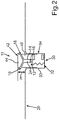
- Fig. 2 shows a further embodiment.
- the motor vehicle exterior microphone 11 comprises a displaceable cylinder 42, which in turn comprises a microphone unit 12 and a switching device 30.
- the displaceable cylinder 42 is arranged in a recess 33 in a vehicle surface, for example the vehicle roof 20.
- the spring device 32 presses the upper part of the displaceable cylinder 42 out of the vehicle surface 20. As a result, the openings 18 of the microphone 12 are exposed. If the upper part 44 of the movable cylinder 42 is coupled to the lower part 46 only by means of support devices, the opening 18 can be designed to run around essentially 360 °, so that the vehicle exterior microphone 11 enables reception in essentially all spatial directions. That in the representation of Fig. 2
- the lower element of the electromagnet 34 is fixed in the vehicle, the upper element in the cylinder 42. The same applies to the spring device 32.
- the cylinder 42 preferably has a diameter between 5 and 15 mm.
- Such displaceable cylinders 42 can be provided at any points on the vehicle surface 20.
Landscapes
- Engineering & Computer Science (AREA)
- Mechanical Engineering (AREA)
- Physics & Mathematics (AREA)
- Acoustics & Sound (AREA)
- Signal Processing (AREA)
- Remote Sensing (AREA)
- Fittings On The Vehicle Exterior For Carrying Loads, And Devices For Holding Or Mounting Articles (AREA)
- Support Of Aerials (AREA)
Description
- Die vorliegende Erfindung betrifft eine Kraftfahrzeugdachantenne mit mindestens einem Kraftfahrzeugaußenmikrofon mit mindestens einer Mikrofoneinheit, die eine in einem Mikrofongehäuse angeordnete Mikrofonkapsel aufweist, wobei das Mikrofongehäuse mindestens eine Mikrofonöffnung aufweist, wodurch ein akustischer Kanal zwischen der mindestens einen Mikrofonöffnung und der Mikrofonkapsel gebildet ist, wobei das Kraftfahrzeugaußenmikrofon eine Umschaltvorrichtung umfasst, die ausgebildet ist, die mindestens eine Mikrofonöffnung in einem aktivierten Zustand des Kraftfahrzeugaußenmikrofons freizugeben und in einem deaktivierten Zustand des Kraftfahrzeugaußenmikrofons zu verschließen. Sie betrifft überdies ein Kraftfahrzeug mit mindestens einem Kraftfahrzeugaußenmikrofon. Schließlich betrifft die Erfindung ein Verfahren zum Betreiben einer Kraftfahrzeugdachantenne.
- Aus der
JP 2007 235316 A - Aus der
DE 10 2014 225 803 A1 ist eine Erkennungseinrichtung zum Erkennen eines sich im Straßenverkehr im Einsatz befindlichen, Leuchtsignale abgebenden Einsatzfahrzeugs bekannt, die zum Einbau in ein Fahrzeug vorgesehen ist. Die Erkennungseinrichtung kann eine akustische Sensoreinrichtung umfassen, mit der akustische Signale von Einsatzfahrzeugen erfassbar sind. - In diesem Zusammenhang ist aus der
DE 102 03 599 A1 eine Mikrofonbaugruppe für eine Fahrzeugfreisprecheinrichtung bekannt, wobei die Mikrofonbaugruppe eine Mikrofoneinheit umfasst, die zwischen einer eingefahrenen und einer ausgefahrenen Stellung reversibel verfahrbar ist. Die Mikrofonbaugruppe ist im Fahrzeuginnenraum angeordnet, insbesondere in einer Einbuchtung einer Dachhimmelverkleidung. - Aus der
DE 100 38 803 A1 ist ein System zum Öffnen eines Kraftfahrzeugs bekannt. Das System umfasst ein an einer Fahrzeugaußenstruktur angeordnetes Mikrofon, das zum Empfang einer Spracheingabe dient. In einem Ausführungsbeispiel sind zwei Mikrofone in einem Kraftfahrzeugemblem angeordnet. Alternativ oder zusätzlich sind zwei Mikrofone in den Rückleuchten des Kraftfahrzeugs integriert. - Die
DE 10 2014 225 397 A1 betrifft die Erkennung eines Rettungsfahrzeugs mit einem digitalen Bildsensor durch ein Fahrzeug. Zur Erkennung des Rettungsfahrzeugs dient ein Mikrofon, das außerhalb des Fahrzeugs angeordnet ist. - Mit den aus dem Stand der Technik bekannten Kraftfahrzeugaußenmikrofonen lässt sich häufig keine ausreichende Empfangsqualität sicherstellen, um eine Sprachbedienbarkeit eines Kraftfahrzeugs von außen zu ermöglichen. Je besser die Spracherkennung, umso unterschiedlicher können die vom Kraftfahrzeug umzusetzenden Sprachbefehle eines Benutzers sein, beispielsweise Öffnen des Kofferraums, Licht an, Entriegeln des Kraftfahrzeugs, etc. Weiterhin soll die Spracherkennung möglichst in einem 360°-Umfeld um das Kraftfahrzeug herum ermöglicht werden.
- Die Aufgabe der vorliegenden Erfindung besteht deshalb darin, eine verbesserte Sprachbedienbarkeit eines Kraftfahrzeugs von außen bereitzustellen.
- Diese Aufgabe wird gelöst durch eine Kraftfahrzeugdachantenne mit den Merkmalen von Patentanspruch 1, ein Kraftfahrzeug mit mindestens einem Kraftfahrzeugaußenmikrofon nach Patentanspruch 7 sowie durch ein Verfahren zum Betreiben einer Kraftfahrzeugdachantenne mit den Merkmalen von Patentanspruch 11.
- Der vorliegenden Erfindung liegt die Erkenntnis zugrunde, dass ein Kraftfahrzeugaußenmikrofon entsprechend im Außenbereich eines Kraftfahrzeugs angeordnet sein muss, um Sprachbefehle der sprachbedienenden Person zu detektieren. Da es sich bei Mikrofonen um Druckempfänger handelt, müssen diese akustische Öffnungen haben, um die Schallsignale empfangen zu können. Werden die Öffnungen verschlossen, sind diese zwar geschützt gegen Staub, Schmutz, Wasser, Schnee und dergleichen, allerdings geht ihre Empfangsqualität dadurch deutlich zurück. Werden die Öffnungen dauerhaft offen gehalten, besteht die Gefahr einer Verunreinigung durch Staub, Schmutz, Wasser, Schnee und dergleichen. Gerade bei im Regen fahrenden Fahrzeugen oder wenn sich diese in einer Waschanlage befinden, wären die Mikrofone erheblichen Umwelteinflüssen ausgesetzt, würden nach Verschmutzung nicht mehr ihrer eigentlichen Spezifikation entsprechen und der Beamformingalgorithmus und damit die Spracherkennung wäre beeinträchtigt.
- Die Erfindung basiert weiterhin auf der Erkenntnis, dass die Sprachbedienbarkeit von außen im Wesentlichen im Stillstand des Kraftfahrzeugs benötigt wird, wohingegen bei sich bewegendem Kraftfahrzeug die Bedienung mittels Sprachbefehlen im Innenraum des Kraftfahrzeugs unter Verwendung von Innenraummikrofonen erfolgen kann. Insofern genügt es, wenn die Öffnungen der Mikrofone lediglich im Stillstand eines Kraftfahrzeugs freigegeben werden, wohingegen sie zum Schutz der Mikrofone im sich bewegenden Kraftfahrzeug verschlossen werden. Damit kann einerseits im Stillstand des Kraftfahrzeug eine hervorragende Sprachbedienbarkeit bereitgestellt werden; andererseits werden die Mikrofone in der Phase, in der sie nicht benötigt werden, zuverlässig vor Verschmutzung und dergleichen geschützt.
- Eine erfindungsgemäße Kraftfahrzugdachantenne weist deshalb weiterhin eine Umschaltvorrichtung auf, die ausgebildet ist, die mindestens eine Mikrofonöffnung in einem aktivierten Zustand des Kraftfahrzeugaußenmikrofons freizugeben und in einem deaktivierten Zustand des Kraftfahrzeugaußenmikrofons zu verschließen. Damit stellt das Kraftfahrzeugaußenmikrofon für die Schallerkennung bei stehendem Kraftfahrzeug eine hervorragende Empfangsqualität bereit, wohingegen während der Fahrt des Kraftfahrzeugs ein Zusetzen der mindestens einen Mikrofonöffnung durch Schmutz, Staub, Wasser und dergleichen zuverlässig verhindert wird.
- Erfindungsgemäß ist weiterhin vorgesehen, dass die Kraftfahrzeugdachantenne einen Basiskörper zum Montieren auf ein Fahrzeugdach und einen daran gekoppelten Antennenkörper umfasst, wobei mittels der Umschaltvorrichtung zumindest ein Element des Basiskörpers oder des Antennenkörpers, bevorzugt der Antennenkörper selbst, bewegbar ist. Durch die Relativbewegung zwischen Basiskörper und Antennenkörper kann demnach die Mikrofonöffnung mindestens einer Mikrofoneinheit geöffnet oder verschlossen werden, um das Kraftfahrzeugaußenmikrofon in den aktivierten oder den deaktivierten Zustand zu versetzen. Durch die Unterbringung des Kraftfahrzeugaußenmikrofons, bevorzugt mit einer Vielzahl von Mikrofoneinheiten, beispielsweise fünf Mikrofoneinheiten, in der Kraftfahrzeugdachantenne kann die gewünschte 360° Umfeld-Abdeckung um das Kraftfahrzeug herum bereitgestellt werden.
- Eine bevorzugte Ausführungsform zeichnet sich dadurch aus, dass die Umschaltvorrichtung als Verstellvorrichtung einen Stellmotor umfasst, um das Kraftfahrzeugaußenmikrofon vom deaktivierten Zustand in den aktivierten Zustand zu versetzen oder umgekehrt. Mittels eines Stellmotors kann das Kraftfahrzeugaußenmikrofon besonders zuverlässig vom aktivierten in den deaktivierten Zustand versetzt werden oder umgekehrt. Durch die Verwendung eines Stellmotors kann das Kraftfahrzeugaußenmikrofon ohne weiteren Energiebedarf, das heißt stromlos, in dem jeweiligen gewünschten Zustand gehalten werden.
- Alternativ oder zusätzlich kann die Umschaltvorrichtung als Verstellvorrichtung mindestens eine Elektromagnetvorrichtung sowie eine Ansteuervorrichtung für die Elektromagnetvorrichtung umfassen, wobei die Elektromagnetvorrichtung ein erstes und ein zweites Element umfasst, wobei das erste Element beweglich gegenüber dem zweiten Element gelagert ist, und wobei eines der beiden Elemente ortsfest mit der Mikrofonöffnung gekoppelt ist, wobei die Ansteuervorrichtung ausgelegt ist, die Elektromagnetvorrichtung derart anzusteuern, dass sich das erste und das zweite Element in einem Zustand anziehen und/oder in einem anderen Zustand abstoßen oder jedenfalls nicht anziehen, um die mindestens eine Mikrofonöffnung zu verschließen und freizugeben oder umgekehrt. Die Verwendung einer Elektromagnetvorrichtung stellt eine besonders kostengünstige Möglichkeit bereit, das Kraftfahrzeugaußenmikrofon vom deaktivierten Zustand in den aktivierten Zustand zu versetzen oder umgekehrt.
- Bei beiden Varianten kann die Umschaltvorrichtung mindestens eine Federvorrichtung umfassen, die derart angeordnet ist, dass sie der Verstellvorrichtung entgegenwirkt. Wird demnach die jeweilige Verstellvorrichtung so ausgelegt, dass damit das Kraftfahrzeugaußenmikrofon in den aktivierten Zustand versetzt wird, so wird das Kraftfahrzeugaußenmikrofon mittels der Federvorrichtung ohne weiteren Energiebedarf zuverlässig im deaktivierten Zustand gehalten. Zum Aktivieren des Kraftfahrzeugaußenmikrofons wird demnach bevorzugt die Federvorrichtung gespannt, sodass sie im deaktivierten Zustand des Kraftfahrzeugaußenmikrofons sich in einem demgegenüber entspannteren Zustand befindet.
- Da in dem Fall eine Vielzahl von Mikrofoneinheiten auf engem Raum angeordnet ist, die zugleich aktiviert bzw. deaktiviert werden, genügt es, die Umschaltvorrichtung nur einmal vorzusehen.
- Bevorzugt ist die Umschaltvorrichtung ausgebildet, den Antennenkörper relativ zum Basiskörper zu bewegen, sodass zum Freigeben der mindestens einen Mikrofonöffnung zumindest eine Öffnung, bevorzugt ein umlaufender Spalt, insbesondere ein umlaufender Spalt mit einer Breite zwischen 1 und 3 mm, zwischen dem Basiskörper und dem Antennenkörper erzeugt wird. Dabei kann jeder Mikrofonöffnung eine separate Öffnung zugeordnet sein oder ein umlaufender Spalt allen Mikrofonöffnungen. Damit kann durch eine einzige Bewegung des Antennenkörpers relativ zum Basiskörper die Mikrofonöffnung von einer Vielzahl von Mikrofoneinheiten freigegeben werden. Ein Hub zwischen 1 und 3 mm genügt, um einen ausreichend breiten akustischen Kanal zu erzeugen, um eine hohe Empfangsqualität von Sprachsignalen sicherzustellen.
- Bevorzugt ragt die mindestens eine Mikrofonöffnung in die Öffnung zwischen dem Basiskörper und dem Antennenkörper, wobei die Mikrofonkapsel im Einbauzustand des Kraftfahrzeugaußenmikrofons oberhalb der Öffnung angeordnet ist, wobei das Mikrofongehäuse bevorzugt wasserdicht ausgebildet ist. Dadurch wird sichergestellt, dass bei einem Wassersäulentest, bei dem die Kraftfahrzeugantenne mit einem Wasserdruck entsprechend einer 1 m hohen Wassersäule belastet wird, die Mikrofonkapsel nicht vom Wasser erreicht wird und somit entsprechend geschützt ist.
- Gemäß einem weiteren Aspekt betrifft die Erfindung ein Kraftfahrzeug mit mindestens einem Kraftfahrzeugaußenmikrofon mit mindestens einer Mikrofoneinheit, die eine in einem Mikrofongehäuse angeordnete Mikrofonkapsel aufweist, wobei das Mikrofongehäuse mindestens eine Mikrofonöffnung aufweist, wodurch ein akustischer Kanal zwischen der mindestens einen Mikrofonöffnung und der Mikrofonkapsel gebildet ist, wobei das Kraftfahrzeugaußenmikrofon eine Umschaltvorrichtung umfasst, die ausgebildet ist, die mindestens eine Mikrofonöffnung in einem aktivierten Zustand des Kraftfahrzeugmikrofons freizugeben und in einem deaktivierten Zustand des Kraftfahrzeugmikrofons zu verschließen, wobei das Kraftfahrzeug eine Kraftfahrzeugaußenoberfläche mit mindestens einer Ausnehmung aufweist, in der das mindestens eine Kraftfahrzeugaußenmikrofon im deaktivierten Zustand angeordnet ist, wobei im aktivierten Zustand des Kraftfahrzeugaußenmikrofons die mindestens eine Mikrofonöffnung aus der Kraftfahrzeugaußenoberfläche herausragt. Damit kann das Kraftfahrzeugaußenmikrofon auch außerhalb der Kraftfahrzeugdachantenne angeordnet sein. Die Positionierung des mindestens einen Kraftfahrzeugaußenmikrofons kann überall am Kraftfahrzeug erfolgen, abhängig von der Parametrierung eines entsprechenden Erkenneralgorithmus zur Spracherkennung.
- Bevorzugt wird ein Teil des Kraftfahrzeugaußenmikrofons mittels der Umschaltvorrichtung, insbesondere um 1 bis 3 mm, aus der Kraftfahrzeugaußenoberfläche herausbewegt, um das Kraftfahrzeugaußenmikrofon in den aktivierten Zustand zu versetzen. Zum Deaktivieren wird das Kraftfahrzeugaußenmikrofon wieder in die Ausnehmung der Kraftfahrzeugaußenoberfläche versenkt. Damit wird das Mikrofon im deaktivierten Zustand geschützt. Der CW-Wert des Kraftfahrzeugs wird durch das Kraftfahrzeugaußenmikrofon daher nicht nachteilig beeinflusst.
- Erfindungsgemäß umfasst das Kraftfahrzeug eine Steuervorrichtung, wobei die Steuervorrichtung ausgelegt ist, beim Feststellen einer Verriegelung des Kraftfahrzeugs das mindestens eine Kraftfahrzeugaußenmikrofon in den aktivierten Zustand zu versetzen. Auf diese Weise wird das Kraftfahrzeugaußenmikrofon genau dann aktiviert, wenn es benötigt wird, nämlich im Stillstand des Kraftfahrzeugs. Eine manuelle Aktivierung des Kraftfahrzeugaußenmikrofons, die auch leicht vergessen werden kann, ist deshalb nicht nötig.
- In diesem Zusammenhang ist die Steuervorrichtung bevorzugt ausgelegt, zumindest beim Feststellen eines Startens des Kraftfahrzeugs das mindestens eine Kraftfahrzeugaußenmikrofon in den deaktivierten Zustand zu versetzen. Da davon auszugehen ist, dass das Kraftfahrzeug nach dem Starten bewegt wird, ist dies genau der richtige Zeitpunkt, um ein automatisches Deaktivieren und damit Schützen des Kraftfahrzeugaußenmikrofons zu veranlassen. Da dies, wie erwähnt, an das Starten des Kraftfahrzeugs gekoppelt ist, braucht ein Benutzer des Kraftfahrzeugs das Kraftfahrzeugaußenmikrofon nicht manuell zu deaktivieren, was leicht vergessen werden kann.
- Bevorzugt ist die Steuervorrichtung ausgelegt, nach Ablauf einer vorbestimmten Zeitdauer nach dem Verriegeln des Kraftfahrzeugs das mindestens eine Kraftfahrzeugaußenmikrofon in den deaktivierten Zustand zu versetzen, wobei die Steuervorrichtung ausgelegt ist, bei Feststellen einer Annäherung eines autorisierten Benutzers unter einen vorgebbaren Schwellenwert das mindestens eines Kraftfahrzeugaußenmikrofon wieder in den aktivierten Zustand zu versetzen. Auf diese Weise wird sichergestellt, dass die Mikrofonöffnungen dann, wenn das Kraftfahrzeug sich längere Zeit im Ruhezustand befindet, nicht unerwünscht lange ungeschützt sind. Die Annäherung eines autorisierten Benutzers kann beispielsweise über ein mobiles Endgerät, insbesondere ein vom Benutzer mitgeführtes Smartphone, kraftfahrzeugseitig detektiert werden. Mittels einschlägiger NFC Techniken, insbesondere Bluetooth Low Energy, kann entsprechend die Mikrofonverfügbarkeit rechtzeitig initialisiert werden, sodass das Kraftfahrzeugaußenmikrofon funktionsbereit ist, wenn sich der Benutzer in einer sprachbedienbaren Entfernung zum Kraftfahrzeug befindet. Auf diese Weise sind die Mikrofonöffnungen nur für den tatsächlich relevanten Zeitraum geöffnet.
- Das Kraftfahrzeug kann weiterhin mindestens eine Sensorvorrichtung umfassen, die ausgelegt ist, festzustellen, ob das Kraftfahrzeug in einer Waschanlage abgestellt und verriegelt wurde, wobei die mindestens eine Sensorvorrichtung mit der Steuervorrichtung gekoppelt ist und die Steuervorrichtung ausgelegt ist, bei Feststellen eines Abstellens und Verriegelns des Kraftfahrzeugs in einer Waschanlage das mindestens eine Kraftfahrzeugaußenmikrofon zu deaktivieren und/oder im deaktivierten Zustand zu belassen. Auf diese Weise werden die Mikrofonöffnungen vor den enormen Wasserdrücken geschützt, die an einer Waschanlage auftreten, auch wenn das Fahrzeug über einen automatischen Aktivierungsmechanismus, siehe oben, verfügt. Als Sensorvorrichtung kann insbesondere ein Regensensor, eine Kameravorrichtung oder ein Ortungssystem, beispielsweise ein Navigationssystem auf GPS-Basis, fungieren. Hiermit lässt sich zuverlässig feststellen, dass sich das Kraftfahrzeug in einer Waschanlage befindet und das mindestens eine Kraftfahrzeugaußenmikrofon zu seinem Schutz in den deaktivierten Zustand versetzt werden muss.
- Die mit Bezug auf die erfindungsgemäße Kraftfahrzeugdachantenne sowie das erfindungsgemäße Kraftfahrzeug vorgestellten bevorzugten Ausführungsformen und deren Vorteile gelten entsprechend, soweit anwendbar, für das erfindungsgemäße Verfahren zum Betreiben einer Kraftfahrzeugdachantenne.
- Im Nachfolgenden werden nunmehr Ausführungsbeispiele der vorliegenden Erfindung unter Bezugnahme auf die beigefügten Zeichnungen näher beschrieben. Diese zeigen:
- Fig. 1
- in schematischer Darstellung ein Ausführungsbeispiel einer erfindungsgemäßen Kraftfahrzeugdachantenne mit einem Kraftfahrzeugaußenmikrofon im aktivierten Zustand des Kraftfahrzeugaußenmikrofons (
Fig. 1a ) sowie im deaktivierten Zustand des Kraftfahrzeugaußenmikrofons (Fig. 1b ); und - Fig. 2
- in schematischer Darstellung ein weiteres Ausführungsbeispiel eines Kraftfahrzeugaußenmikrofons.
-
Fig. 1 zeigt in schematischer Darstellung eine erfindungsgemäße Kraftfahrzeugdachantenne 10, wobeiFig. 1a die Kraftfahrzeugdachantenne 10 mit aktiviertem Kraftfahrzeugaußenmikrofon 11 zeigt undFig. 1b die Kraftfahrzeugdachantenne 10 mit deaktiviertem Kraftfahrzeugaußenmikrofon 11. Das Kraftfahrzeugaußenmikrofon 11 umfasst vorliegend mehrere Mikrofoneinheiten 12a bis 12c mit jeweils einem wasserdichten Gehäuse 14, in dessen oberem Bereich, d.h. einer Öffnung 18 diametral gegenüberliegenden Seite des Gehäuses 14, eine Mikrofonkapsel 16 angeordnet ist. Die Öffnung 18 ist in Richtung des Fahrzeugdachs 20 orientiert und ist bevorzugt mit einer wasserundurchlässigen und windschützenden Membran 22 versehen, um die Mikrofonkapsel 16 bei Regen oder Wind auch bei stehendem Kraftfahrzeug zu schützen. Zwischen der Öffnung 18 und der Mikrofonkapsel 16 wird ein akustischer Kanal 24 gebildet. - Die Kraftfahrzeugdachantenne 10 umfasst einen Basiskörper 26, der auf dem Fahrzeugdach 20 befestigt ist. Der Basiskörper 26 bildet einen Antennenfuß und einen inneren Antennenkörper. Hier sind die Mikrofoneinheiten 12 und weitere Elektronik verortet. Die Kraftfahrzeugdachantenne 10 umfasst weiterhin einen Antennenkörper 28, der relativ zum Basiskörper 26 bewegbar gelagert ist. Der Antennenkörper 28 weist vorliegend eine Finnenform auf. Zum Zweck der Relativbewegung ist eine Umschaltvorrichtung 30 vorgesehen, die im dargestellten Ausführungsbeispiel eine Federvorrichtung 32 und einen Elektromagneten 34 mit zwei zusammenwirkenden Elementen umfasst. Das in der Darstellung obere Element des Elektromagneten 34 ist fest mit dem Antennenkörper 28 verbunden, während das untere Element des Elektromagneten 34 fest mit dem Basiskörper 26 verbunden ist. Vorliegend dient eine einzige Umschaltvorrichtung 30 zum Umschalten jeder Mikrofoneinheit 12a bis 12c. Mit anderen Worten umfasst das Kraftfahrzeugaußenmikrofon 11 vorliegend eine Vielzahl von Mikrofoneinheiten 12a bis 12c.
-
Fig. 1a zeigt den Zustand bei aktiviertem Kraftfahrzeugaußenmikrofon 11, der daran erkennbar ist, dass sich der Antennenkörper 28 unter Ausbildung eines Spalts 36, der eine Breite H aufweist, vom Basiskörper 26 wegbewegt hat. Dies wird dadurch erreicht, dass der Elektromagnet 34 nicht bestromt wird, wobei die Federvorrichtung 32 derart ausgelegt ist, dass sie bei nicht bestromtem Elektromagneten 34 den Antennenkörper 28 vom Basiskörper 26 wegdrückt. Um eine feste Breite H des Spalts 36 sicherzustellen, sind nicht dargestellte Begrenzungselemente vorgesehen, die die Relativbewegung des Antennenkörpers 28 gegenüber dem Basiskörper 26 begrenzen. - Die Öffnungen 18 der Mikrofoneinheiten 12 münden in den Spalt 36. Wenngleich vorliegend ein umlaufender Spalt 36 dargestellt ist, genügen auch einzelne Öffnungen im Bereich der Mikrofone 12, so dass diese geöffnet und verschlossen werden können.
-
Fig. 1b zeigt den Zustand bei deaktiviertem Kraftfahrzeugaußenmikrofon 11. Dieser Zustand wird erreicht durch Bestromung des Elektromagneten 34. Dadurch wird der Antennenkörper 28 unter Schließung des Spalts 36 auf den Basiskörper 26 zubewegt. Gleichzeitig wird die Federvorrichtung 32 gespannt. Die Öffnungen 18 der Mikrofoneinheiten 12 werden verschlossen. - Alternativ zu der Umschaltvorrichtung von
Fig. 1 kann auch ein Stellmotor vorgesehen werden, um den umlaufenden Spalt bzw. die Öffnungen zu öffnen und zu schließen. - Eine Steuervorrichtung 38 ist ausgelegt, beim Feststellen einer Verriegelung des Kraftfahrzeugs das Kraftfahrzeugaußenmikrofon 11 in den aktivierten Zustand zu versetzen. Beim Feststellen des Startens des Kraftfahrzeugs oder wenn festgestellt wird, dass sich das Kraftfahrzeug in Bewegung setzt oder die Zündung eingeschaltet wird, wird das Kraftfahrzeugaußenmikrofon 11 in den deaktivierten Zustand versetzt.
- Die Steuervorrichtung 38 kann ausgelegt sein, nach Ablauf einer vorbestimmten Zeitdauer nach dem Verriegeln des Kraftfahrzeugs das Kraftfahrzeugaußenmikrofon 11 in den deaktivierten Zustand zu versetzen, wobei die Steuervorrichtung 38 ausgelegt ist, bei Feststellen einer Annäherung eines autorisierten Benutzers unter einem vorgebbaren Schwellenwert das Kraftfahrzeugaußenmikrofon 11 wieder in den aktivierten Zustand zu versetzen. Der Hub H beträgt bevorzugt zwischen 1 und 3 mm. Der Hub sollte möglichst gering sein, damit die Öffnungen 18 auch bei stehendem Fahrzeug vor Umwelteinflüssen geschützt sind. Ein geringer Hub H ist auch für eine designtechnisch möglichst unauffällige Realisierung des Spalts 36 anzustreben. Aufgrund der passiven Federwirkung wird bei abgestelltem Fahrzeug kein Ruhestrom verbraucht, um den Spalt 36 offen zu halten.
- Das Fahrzeug kann eine Sensorvorrichtung 40 umfassen, die ausgelegt ist, festzustellen, ob das Kraftfahrzeug in einer Waschanlage abgestellt und verriegelt wurde. Die Sensorvorrichtung 40 ist mit der Steuervorrichtung 38 gekoppelt, wobei die Steuervorrichtung 38 ausgelegt ist, bei Feststellen eines Abstellens und Verriegelns des Kraftfahrzeugs in einer Waschanlage das Kraftfahrzeugaußenmikrofon 11 zu deaktivieren und/oder im deaktivierten Zustand zu belassen.
-
Fig. 2 zeigt ein weiteres Ausführungsbeispiel. Dieses Ausführungsbeispiel zeichnet sich dadurch aus, dass das Kraftfahrzeugaußenmikrofon 11 einen verfahrbaren Zylinder 42 umfasst, der seinerseits eine Mikrofoneinheit 12 und eine Umschaltvorrichtung 30 umfasst. Der verfahrbare Zylinder 42 ist in einer Ausnehmung 33 einer Fahrzeugoberfläche, beispielsweise des Fahrzeugdachs 20, angeordnet. - Ohne Bestromung des Elektromagneten 34 drückt die Federvorrichtung 32 den oberen Teil des verfahrbaren Zylinders 42 aus der Fahrzeugoberfläche 20 heraus. Dadurch werden die Öffnungen 18 des Mikrofons 12 freigegeben. Wird der obere Teil 44 des verfahrbaren Zylinders 42 lediglich durch Stützvorrichtungen mit dem unteren Teil 46 gekoppelt, kann die Öffnung 18 im Wesentlichen über 360° umlaufend ausgebildet sein, sodass mit dem Kraftfahrzeugaußenmikrofon 11 ein Empfang in im Wesentlichen alle Raumrichtungen ermöglicht ist. Das in der Darstellung von
Fig. 2 untere Element des Elektromagneten 34 ist im Fahrzeug fixiert, das obere Element im Zylinder 42. Entsprechendes gilt für die Federvorrichtung 32. Der Zylinder 42 weist bevorzugt einen Durchmesser zwischen 5 und 15 mm auf. - Derartige verfahrbare Zylinder 42 können an beliebigen Stellen der Fahrzeugoberfläche 20 vorgesehen sein.
Claims (11)
- Kraftfahrzeugdachantenne (10) mit mindestens einem Kraftfahrzeugaußenmikrofon (11) mit mindestens einer Mikrofoneinheit (12), die eine in einem Mikrofongehäuse (14) angeordnete Mikrofonkapsel (16) aufweist, wobei das Mikrofongehäuse (14) mindestens eine Mikrofonöffnung (18) aufweist, wodurch ein akustischer Kanal (24) zwischen der mindestens einen Mikrofonöffnung (18) und der Mikrofonkapsel gebildet ist, wobei das Kraftfahrzeugaußenmikrofon (11) eine Umschaltvorrichtung (30) umfasst, die ausgebildet ist die mindestens eine Mikrofonöffnung (18) in einem aktivierten Zustand des Kraftfahrzeugaußenmikrofons (11) freizugeben und in einem deaktivierten Zustand des Kraftfahrzeugaußenmikrofons (11) zu verschließen,
wobei die Kraftfahrzeugdachantenne (10) einen Basiskörper (26) zum Montieren auf ein Fahrzeugdach (20) und einen daran gekoppelten Antennenkörper (28) umfasst, wobei mittels der Umschaltvorrichtung (30) zumindest ein Element des Basiskörpers (26) oder des Antennenkörpers (28) bewegbar ist. - Kraftfahrzeugdachantenne (10) nach Anspruch 1,
dadurch gekennzeichnet, dass
die Umschaltvorrichtung (30) als Verstellvorrichtung einen Stellmotor umfasst, um das Kraftfahrzeugaußenmikrofon (11) vom deaktivierten Zustand in den aktivierten Zustand zu versetzen oder umgekehrt. - Kraftfahrzeugdachantenne (10) nach Anspruch 1 ,
dadurch gekennzeichnet, dass
die Umschaltvorrichtung (30) als Verstellvorrichtung mindestens eine Elektromagnetvorrichtung (34) sowie eine Ansteuervorrichtung (38) für die Elektromagnetvorrichtung (34) umfasst, wobei die Elektromagnetvorrichtung (34) ein erstes und ein zweites Element umfasst, wobei das erste Element beweglich gegenüber dem zweiten Element gelagert ist, und wobei eines der beiden Elemente ortsfest mit der Mikrofonöffnung (18) gekoppelt ist, wobei die Ansteuervorrichtung (38) ausgelegt ist, die Elektromagnetvorrichtung (34) derart anzusteuern, dass sich das erste und das zweite Element in einem Zustand anziehen und/oder in einem anderen Zustand abstoßen oder jedenfalls nicht anziehen, um die mindestens eine Mikrofonöffnung (18) zu verschließen und freizugeben oder umgekehrt. - Kraftfahrzeugdachantenne (10) nach einem der Ansprüche 2 oder 3,
dadurch gekennzeichnet, dass
die Umschaltvorrichtung (30) mindestens eine Federvorrichtung umfasst, die derart angeordnet ist, dass sie der Verstellvorrichtung entgegenwirkt. - Kraftfahrzeugdachantenne (10) nach einem der vorhergehenden Ansprüche,
dadurch gekennzeichnet, dass
die Umschaltvorrichtung (30) ausgebildet ist, den Antennenkörper (28) relativ zum Basiskörper (26) zu bewegen, so dass zum Freigeben der mindestens einen Mikrofonöffnung (18) zumindest eine Öffnung (36), bevorzugt ein umlaufender Spalt, insbesondere ein umlaufender Spalt mit einer Breite (H) zwischen 1 und 3 mm, zwischen dem Basiskörper (26) und dem Antennenkörper (28) erzeugt wird. - Kraftfahrzeugdachantenne (10) nach Anspruch 5,
dadurch gekennzeichnet, dass
die mindestens eine Mikrofonöffnung (18) in die Öffnung (36) zwischen dem Basiskörper (26) und dem Antennenkörper (28) ragt, wobei die Mikrofonkapsel (16) im Einbauzustand des Kraftfahrzeugaußenmikrofons (11) oberhalb der Öffnung (36) angeordnet ist, wobei das Mikrofongehäuse (14) bevorzugt wasserdicht ausgebildet ist. - Kraftfahrzeug mit mindestens einem Kraftfahrzeugaußenmikrofon (11), mit mindestens einer Mikrofoneinheit (12), die eine in einem Mikrofongehäuse (14) angeordnete Mikrofonkapsel (16) aufweist, wobei das Mikrofongehäuse (14) mindestens eine Mikrofonöffnung (18) aufweist, wodurch ein akustischer Kanal (24) zwischen der mindestens einen Mikrofonöffnung (18) und der Mikrofonkapsel gebildet ist, wobei das Kraftfahrzeugaußenmikrofon (11) eine Umschaltvorrichtung (30) umfasst, die ausgebildet ist die mindestens eine Mikrofonöffnung (18) in einem aktivierten Zustand des Kraftfahrzeugaußenmikrofons (11) freizugeben und in einem deaktivierten Zustand des Kraftfahrzeugaußenmikrofons (11) zu verschließen, wobei das Kraftfahrzeug eine Kraftfahrzeugaußenoberfläche (20) mit mindestens einer Ausnehmung (33) aufweist, in der das mindestens eine Kraftfahrzeugaußenmikrofon (11) im deaktivierten Zustand angeordnet ist, wobei im aktivierten Zustand des Kraftfahrzeugaußenmikrofons (11) die mindestens eine Mikrofonöffnung (18) aus der Kraftfahrzeugaußenoberfläche (20) herausragt,
dadurch gekennzeichnet,
dass das Kraftfahrzeug eine Steuervorrichtung (38) umfasst, wobei die Steuervorrichtung (38) ausgelegt ist, beim Feststellen einer Verriegelung des Kraftfahrzeugs das mindestens eine Kraftfahrzeugaußenmikrofon (11) in den aktivierten Zustand zu versetzen. - Kraftfahrzeug nach Anspruch 7,
dadurch gekennzeichnet, dass
die Steuervorrichtung (38) ausgelegt ist, zumindest beim Feststellen eines Startens des Kraftfahrzeugs das mindestens eine Kraftfahrzeugaußenmikrofon (11) in den deaktivierten Zustand zu versetzen. - Kraftfahrzeug nach einem der Ansprüche 7 oder 8,
dadurch gekennzeichnet, dass
die Steuervorrichtung (38) ausgelegt ist, nach Ablauf einer vorbestimmten Zeitdauer nach dem Verriegeln des Kraftfahrzeugs das mindestens eine Kraftfahrzeugaußenmikrofon (11) in den deaktivierten Zustand zu versetzen, wobei die Steuervorrichtung (38) ausgelegt ist, bei Feststellen einer Annäherung eines autorisierten Benutzers unter einen vorgebbaren Schwellenwert das mindestens eine Kraftfahrzeugaußenmikrofon (11) wieder in den aktivierten Zustand zu versetzen. - Kraftfahrzeug nach einem der Ansprüche 7 bis 9,
dadurch gekennzeichnet, dass
das Kraftfahrzeug mindestens eine Sensorvorrichtung (40) umfasst, die ausgelegt ist festzustellen, ob das Kraftfahrzeug in einer Waschanlage abgestellt und verriegelt wurde, wobei die mindestens eine Sensorvorrichtung (40) mit der Steuervorrichtung (38) gekoppelt ist und die Steuervorrichtung (38) ausgelegt ist, bei Feststellen eines Abstellens und Verriegelns des Kraftfahrzeugs in einer Waschanlage das mindestens eine Kraftfahrzeugaußenmikrofon (11) zu deaktivieren und/oder im deaktivierten Zustand zu belassen. - Verfahren zum Betreiben einer Kraftfahrzeugdachantenne (10) mit mindestens einem Kraftfahrzeugaußenmikrofon (11) mit mindestens einer Mikrofoneinheit (12), die eine in einem Mikrofongehäuse (14) angeordnete Mikrofonkapsel (16) aufweist, wobei das Mikrofongehäuse (14) mindestens eine Mikrofonöffnung (18) aufweist, wodurch ein akustischer Kanal (24) zwischen der mindestens einen Mikrofonöffnung (18) und der Mikrofonkapsel gebildet ist, wobei die Kraftfahrzeugdachantenne (10) einen Basiskörper (26) zum Montieren auf ein Fahrzeugdach (20) und einen daran gekoppelten Antennenkörper (28) umfasst, wobei zumindest ein Element des Basiskörpers (26) oder des Antennenkörpers (28) bewegbar ist, wobei das Verfahren folgende Schritte umfasst:Zum Aktivieren des Kraftfahrzeugaußenmikrofons (11): Freigeben der mindestens einen Mikrofonöffnung (18) durch Bewegen zumindest eines Elements des Basiskörpers (26) oder des Antennenkörpers (28); undzum Deaktivieren des Kraftfahrzeugaußenmikrofons (11): Verschließen der mindestens einen Mikrofonöffnung (18) durch Bewegen zumindest eines Elements des Basiskörpers (26) oder des Antennenkörpers (28).
Applications Claiming Priority (2)
| Application Number | Priority Date | Filing Date | Title |
|---|---|---|---|
| DE102018208776.8A DE102018208776B3 (de) | 2018-06-05 | 2018-06-05 | Kraftfahrzeugaußenmikrofon, Kraftfahrzeugdachantenne und Kraftfahrzeug mit mindestens einem Kraftfahrzeugaußenmikrofon sowie Verfahren zum Betreiben eines Kraftfahrzeugaußenmikrofons |
| PCT/EP2019/061121 WO2019233681A1 (de) | 2018-06-05 | 2019-04-30 | KRAFTFAHRZEUGAUßENMIKROFON, KRAFTFAHRZEUGDACHANTENNE UND KRAFTFAHRZEUG MIT MINDESTENS EINEM KRAFTFAHRZEUGAUßENMIKROFON SOWIE VERFAHREN ZUM BETREIBEN EINES KRAFTFAHRZEUGAUßENMIKROFONS |
Publications (2)
| Publication Number | Publication Date |
|---|---|
| EP3659347A1 EP3659347A1 (de) | 2020-06-03 |
| EP3659347B1 true EP3659347B1 (de) | 2021-03-31 |
Family
ID=66476606
Family Applications (1)
| Application Number | Title | Priority Date | Filing Date |
|---|---|---|---|
| EP19723043.6A Active EP3659347B1 (de) | 2018-06-05 | 2019-04-30 | Kraftfahrzeugdachantenne mit mindestens einem kraftfahrzeugaussenmikrofon, verfahren zum betreiben derselben und kraftfahrzeug mit mindestens einem kraftfahrzeugaussenmikrofon |
Country Status (5)
| Country | Link |
|---|---|
| US (1) | US11380981B2 (de) |
| EP (1) | EP3659347B1 (de) |
| CN (1) | CN111279714B (de) |
| DE (1) | DE102018208776B3 (de) |
| WO (1) | WO2019233681A1 (de) |
Families Citing this family (9)
| Publication number | Priority date | Publication date | Assignee | Title |
|---|---|---|---|---|
| WO2021018492A1 (de) * | 2019-07-30 | 2021-02-04 | Bayerische Motoren Werke Aktiengesellschaft | BAUTEIL ZUR MONTAGE IN EINEM AUßENBEREICH EINES FAHRZEUGS |
| KR102192766B1 (ko) * | 2019-08-19 | 2020-12-18 | 인팩일렉스 주식회사 | 차량용 샤크핀 안테나 |
| DE102019212424B3 (de) * | 2019-08-20 | 2020-10-22 | Audi Ag | Fahrzeugdachantenne für ein Fahrzeug, sowie Kraftfahrzeug |
| DE102019129630A1 (de) * | 2019-11-04 | 2021-05-06 | Audi Ag | Antennensystem |
| US11496821B2 (en) * | 2020-05-05 | 2022-11-08 | Harman International Industries, Incorporated | External microphone active ingress protection |
| CN114435257B (zh) * | 2022-02-21 | 2023-11-14 | 泰弗思科技(安徽)有限公司 | 一种车载报站辅助腔室 |
| EP4354897A1 (de) | 2022-10-14 | 2024-04-17 | Harman International Industries, Inc. | Mikrofonanordnung |
| DE102024121212A1 (de) * | 2024-07-25 | 2026-01-29 | Bayerische Motoren Werke Aktiengesellschaft | Fahrzeug mit einer Einrichtung und Verfahren zum Betreiben eines Fahrzeuges |
| DE102024121210A1 (de) * | 2024-07-25 | 2026-01-29 | Bayerische Motoren Werke Aktiengesellschaft | Fahrzeug mit einer Einrichtung zur Erfassung und Umsetzung akustischer Umgebungssignale und Verfahren zum Betreiben eines Fahrzeuges |
Family Cites Families (12)
| Publication number | Priority date | Publication date | Assignee | Title |
|---|---|---|---|---|
| DE10038803A1 (de) | 2000-08-09 | 2002-02-21 | Volkswagen Ag | System zum Öffnen eines Kraftfahrzeugs |
| DE10203599A1 (de) | 2002-01-30 | 2003-08-07 | Arvinmeritor Gmbh | Mikrophonbaugruppe für Fahrzeugfreisprecheinrichtung und Fahrzeugfreisprecheinrichtung |
| US20050100169A1 (en) * | 2003-11-10 | 2005-05-12 | Kenneth Shelley | Automotive gauge-based sound pressure instrument |
| JP2007235316A (ja) * | 2006-02-28 | 2007-09-13 | Fujitsu Ten Ltd | 車載マイクロホン保護装置、車載マイクロホン装置、及び、接続回路ユニット |
| DE102012212843A1 (de) * | 2012-07-23 | 2014-01-23 | Behr Gmbh & Co. Kg | Klimagerät |
| DE102012017286A1 (de) * | 2012-08-31 | 2014-03-06 | Kiekert Aktiengesellschaft | Kraftfahrzeugtürverschluss und Verfahren zum wahlweisen Betrieb eines solchen Kraftfahrzeugtürverschlusses mit oder ohne Sicherungsvorrichtung |
| DE102012219404A1 (de) * | 2012-10-24 | 2014-04-24 | Bayerische Motoren Werke Aktiengesellschaft | Kraftfahrzeug |
| JP6104692B2 (ja) * | 2013-04-26 | 2017-03-29 | 小島プレス工業株式会社 | 車両搭載用マイクロホンユニット |
| GB2521274B (en) | 2013-12-11 | 2018-07-04 | Continental automotive systems inc | Emergency vehicle detection with digital image sensor |
| DE102014225803A1 (de) * | 2014-12-15 | 2016-06-16 | Bayerische Motoren Werke Aktiengesellschaft | Erkennen eines im Einsatz befindlichen Einsatzfahrzeuges im Straßenverkehr |
| DE102017218542A1 (de) * | 2017-10-17 | 2018-08-16 | Audi Ag | Verfahren zur Sprachsteuerung von Fahrzeugfunktionen eines Kraftfahrzeugs von außerhalb des Kraftfahrzeugs, Dachantennenelement für ein Kraftfahrzeug sowie Kraftfahrzeug mit einem Dachantennenelement |
| DE102018202098B3 (de) * | 2018-02-12 | 2018-12-27 | Audi Ag | Fahrzeugdachantenne |
-
2018
- 2018-06-05 DE DE102018208776.8A patent/DE102018208776B3/de not_active Expired - Fee Related
-
2019
- 2019-04-30 EP EP19723043.6A patent/EP3659347B1/de active Active
- 2019-04-30 CN CN201980005376.2A patent/CN111279714B/zh not_active Expired - Fee Related
- 2019-04-30 US US16/757,143 patent/US11380981B2/en active Active
- 2019-04-30 WO PCT/EP2019/061121 patent/WO2019233681A1/de not_active Ceased
Also Published As
| Publication number | Publication date |
|---|---|
| US11380981B2 (en) | 2022-07-05 |
| EP3659347A1 (de) | 2020-06-03 |
| DE102018208776B3 (de) | 2019-07-18 |
| CN111279714B (zh) | 2021-07-20 |
| WO2019233681A1 (de) | 2019-12-12 |
| US20200343627A1 (en) | 2020-10-29 |
| CN111279714A (zh) | 2020-06-12 |
Similar Documents
| Publication | Publication Date | Title |
|---|---|---|
| EP3659347B1 (de) | Kraftfahrzeugdachantenne mit mindestens einem kraftfahrzeugaussenmikrofon, verfahren zum betreiben derselben und kraftfahrzeug mit mindestens einem kraftfahrzeugaussenmikrofon | |
| EP3020892B1 (de) | Türgriff mit abnehmbarer kappe | |
| DE60120537T2 (de) | Infrarot-Kommunikationssystem für Fahrzeug | |
| DE202009018206U1 (de) | Vorrichtung zur Betätigung einer Tür oder Klappe eines Fahrzeugs | |
| DE102012013065A1 (de) | Verfahren zur Ansteuerung einer Verschlusselementanordnung eines Kraftfahrzeugs | |
| DE202017105516U1 (de) | Entfernte sekundäre Motorhaubenverriegelungsfreigabe | |
| DE10214602B4 (de) | Aktive Fronthaube | |
| DE102018121432A1 (de) | Türgriffanordnung für ein Kraftfahrzeug | |
| EP2642049B1 (de) | Handhabe eines Kraftfahrzeuges mit einem bewegbaren Abdeckelement | |
| DE102017124446A1 (de) | Sensorgesteuertes Schlüsselsystem für ein Kraftfahrzeug sowie Verfahren zur energiesparenden Umfeldüberwachung eines Kraftfahrzeuges | |
| EP1410936A2 (de) | Verriegelungseinrichtung für eine Tankklappe und Verfahren zur Steuerung einer Verriegelungseinrichtung | |
| WO2005037614A1 (de) | Vorrichtung zum schutz von personen bei einem frontalaufprall auf ein kraftfahrzeug durch aufstellen dessen fronthaube | |
| DE102016121886A1 (de) | Aktives Türkantenschutzsystem für ein Kraftfahrzeug | |
| DE102018121433A1 (de) | Türgriffanordnung für ein Kraftfahrzeug | |
| DE10219222A1 (de) | Fahrzeugteil mit Antennenträgerelement | |
| DE102009034170B4 (de) | Türbetätigungsventileinrichtung für eine druckmittelbetätigbare Fahrzeugtüranlage | |
| DE102019122076A1 (de) | Türinnengriffsystem für eine Tür eines Kraftfahrzeugs | |
| DE102018209314A1 (de) | Diebstahlwarnanlage für ein Fahrzeug | |
| DE102022104044B4 (de) | Fahrzeugtür für einen Kraftwagen sowie Verfahren zum Betreiben einer solchen Fahrzeugtür | |
| DE102016211527A1 (de) | Steuervorrichtung für ein Fahrzeug mit automatisch öffnender Klappe | |
| DE102017110232B4 (de) | Assistenzverfahren für ein Lichtsteuerungssystem eines Kraftfahrzeugs, Lichtsteuerungssystem, Computerprogrammprodukt und computerlesbares Medium | |
| EP3032014B1 (de) | Türgriffanordnung für fahrzeuge | |
| DE102021003988A1 (de) | Kamerahalter zur beweglichen Aufnahme einer Kamera und Fahrzeug | |
| DE10354159B4 (de) | Vorrichtung zum reversiblen Aufstellen einer Kfz-Tür, insbesondere einer Kfz-Fronthaube, in einer Unfallsituation | |
| DE102017110245B4 (de) | Assistenzverfahren für ein Lichtsteuerungssystem eines Kraftfahrzeugs, Lichtsteuerungssystem, Computerprogrammprodukt und computerlesbares Medium |
Legal Events
| Date | Code | Title | Description |
|---|---|---|---|
| STAA | Information on the status of an ep patent application or granted ep patent |
Free format text: STATUS: UNKNOWN |
|
| STAA | Information on the status of an ep patent application or granted ep patent |
Free format text: STATUS: THE INTERNATIONAL PUBLICATION HAS BEEN MADE |
|
| PUAI | Public reference made under article 153(3) epc to a published international application that has entered the european phase |
Free format text: ORIGINAL CODE: 0009012 |
|
| STAA | Information on the status of an ep patent application or granted ep patent |
Free format text: STATUS: REQUEST FOR EXAMINATION WAS MADE |
|
| 17P | Request for examination filed |
Effective date: 20200224 |
|
| AK | Designated contracting states |
Kind code of ref document: A1 Designated state(s): AL AT BE BG CH CY CZ DE DK EE ES FI FR GB GR HR HU IE IS IT LI LT LU LV MC MK MT NL NO PL PT RO RS SE SI SK SM TR |
|
| AX | Request for extension of the european patent |
Extension state: BA ME |
|
| GRAJ | Information related to disapproval of communication of intention to grant by the applicant or resumption of examination proceedings by the epo deleted |
Free format text: ORIGINAL CODE: EPIDOSDIGR1 |
|
| STAA | Information on the status of an ep patent application or granted ep patent |
Free format text: STATUS: GRANT OF PATENT IS INTENDED |
|
| GRAP | Despatch of communication of intention to grant a patent |
Free format text: ORIGINAL CODE: EPIDOSNIGR1 |
|
| DAX | Request for extension of the european patent (deleted) | ||
| INTG | Intention to grant announced |
Effective date: 20210121 |
|
| GRAS | Grant fee paid |
Free format text: ORIGINAL CODE: EPIDOSNIGR3 |
|
| GRAA | (expected) grant |
Free format text: ORIGINAL CODE: 0009210 |
|
| STAA | Information on the status of an ep patent application or granted ep patent |
Free format text: STATUS: THE PATENT HAS BEEN GRANTED |
|
| AK | Designated contracting states |
Kind code of ref document: B1 Designated state(s): AL AT BE BG CH CY CZ DE DK EE ES FI FR GB GR HR HU IE IS IT LI LT LU LV MC MK MT NL NO PL PT RO RS SE SI SK SM TR |
|
| DAV | Request for validation of the european patent (deleted) | ||
| REG | Reference to a national code |
Ref country code: GB Ref legal event code: FG4D Free format text: NOT ENGLISH Ref country code: CH Ref legal event code: EP |
|
| REG | Reference to a national code |
Ref country code: DE Ref legal event code: R096 Ref document number: 502019001118 Country of ref document: DE Ref country code: AT Ref legal event code: REF Ref document number: 1378311 Country of ref document: AT Kind code of ref document: T Effective date: 20210415 |
|
| REG | Reference to a national code |
Ref country code: IE Ref legal event code: FG4D Free format text: LANGUAGE OF EP DOCUMENT: GERMAN |
|
| REG | Reference to a national code |
Ref country code: LT Ref legal event code: MG9D |
|
| PG25 | Lapsed in a contracting state [announced via postgrant information from national office to epo] |
Ref country code: NO Free format text: LAPSE BECAUSE OF FAILURE TO SUBMIT A TRANSLATION OF THE DESCRIPTION OR TO PAY THE FEE WITHIN THE PRESCRIBED TIME-LIMIT Effective date: 20210630 Ref country code: HR Free format text: LAPSE BECAUSE OF FAILURE TO SUBMIT A TRANSLATION OF THE DESCRIPTION OR TO PAY THE FEE WITHIN THE PRESCRIBED TIME-LIMIT Effective date: 20210331 Ref country code: BG Free format text: LAPSE BECAUSE OF FAILURE TO SUBMIT A TRANSLATION OF THE DESCRIPTION OR TO PAY THE FEE WITHIN THE PRESCRIBED TIME-LIMIT Effective date: 20210630 Ref country code: FI Free format text: LAPSE BECAUSE OF FAILURE TO SUBMIT A TRANSLATION OF THE DESCRIPTION OR TO PAY THE FEE WITHIN THE PRESCRIBED TIME-LIMIT Effective date: 20210331 |
|
| PG25 | Lapsed in a contracting state [announced via postgrant information from national office to epo] |
Ref country code: LV Free format text: LAPSE BECAUSE OF FAILURE TO SUBMIT A TRANSLATION OF THE DESCRIPTION OR TO PAY THE FEE WITHIN THE PRESCRIBED TIME-LIMIT Effective date: 20210331 Ref country code: SE Free format text: LAPSE BECAUSE OF FAILURE TO SUBMIT A TRANSLATION OF THE DESCRIPTION OR TO PAY THE FEE WITHIN THE PRESCRIBED TIME-LIMIT Effective date: 20210331 Ref country code: RS Free format text: LAPSE BECAUSE OF FAILURE TO SUBMIT A TRANSLATION OF THE DESCRIPTION OR TO PAY THE FEE WITHIN THE PRESCRIBED TIME-LIMIT Effective date: 20210331 |
|
| REG | Reference to a national code |
Ref country code: NL Ref legal event code: MP Effective date: 20210331 |
|
| PG25 | Lapsed in a contracting state [announced via postgrant information from national office to epo] |
Ref country code: SM Free format text: LAPSE BECAUSE OF FAILURE TO SUBMIT A TRANSLATION OF THE DESCRIPTION OR TO PAY THE FEE WITHIN THE PRESCRIBED TIME-LIMIT Effective date: 20210331 Ref country code: NL Free format text: LAPSE BECAUSE OF FAILURE TO SUBMIT A TRANSLATION OF THE DESCRIPTION OR TO PAY THE FEE WITHIN THE PRESCRIBED TIME-LIMIT Effective date: 20210331 Ref country code: EE Free format text: LAPSE BECAUSE OF FAILURE TO SUBMIT A TRANSLATION OF THE DESCRIPTION OR TO PAY THE FEE WITHIN THE PRESCRIBED TIME-LIMIT Effective date: 20210331 Ref country code: CZ Free format text: LAPSE BECAUSE OF FAILURE TO SUBMIT A TRANSLATION OF THE DESCRIPTION OR TO PAY THE FEE WITHIN THE PRESCRIBED TIME-LIMIT Effective date: 20210331 Ref country code: LT Free format text: LAPSE BECAUSE OF FAILURE TO SUBMIT A TRANSLATION OF THE DESCRIPTION OR TO PAY THE FEE WITHIN THE PRESCRIBED TIME-LIMIT Effective date: 20210331 |
|
| PG25 | Lapsed in a contracting state [announced via postgrant information from national office to epo] |
Ref country code: IS Free format text: LAPSE BECAUSE OF FAILURE TO SUBMIT A TRANSLATION OF THE DESCRIPTION OR TO PAY THE FEE WITHIN THE PRESCRIBED TIME-LIMIT Effective date: 20210731 Ref country code: SK Free format text: LAPSE BECAUSE OF FAILURE TO SUBMIT A TRANSLATION OF THE DESCRIPTION OR TO PAY THE FEE WITHIN THE PRESCRIBED TIME-LIMIT Effective date: 20210331 Ref country code: RO Free format text: LAPSE BECAUSE OF FAILURE TO SUBMIT A TRANSLATION OF THE DESCRIPTION OR TO PAY THE FEE WITHIN THE PRESCRIBED TIME-LIMIT Effective date: 20210331 Ref country code: PT Free format text: LAPSE BECAUSE OF FAILURE TO SUBMIT A TRANSLATION OF THE DESCRIPTION OR TO PAY THE FEE WITHIN THE PRESCRIBED TIME-LIMIT Effective date: 20210802 Ref country code: PL Free format text: LAPSE BECAUSE OF FAILURE TO SUBMIT A TRANSLATION OF THE DESCRIPTION OR TO PAY THE FEE WITHIN THE PRESCRIBED TIME-LIMIT Effective date: 20210331 |
|
| PG25 | Lapsed in a contracting state [announced via postgrant information from national office to epo] |
Ref country code: LU Free format text: LAPSE BECAUSE OF NON-PAYMENT OF DUE FEES Effective date: 20210430 |
|
| REG | Reference to a national code |
Ref country code: DE Ref legal event code: R097 Ref document number: 502019001118 Country of ref document: DE |
|
| REG | Reference to a national code |
Ref country code: BE Ref legal event code: MM Effective date: 20210430 |
|
| PG25 | Lapsed in a contracting state [announced via postgrant information from national office to epo] |
Ref country code: DK Free format text: LAPSE BECAUSE OF FAILURE TO SUBMIT A TRANSLATION OF THE DESCRIPTION OR TO PAY THE FEE WITHIN THE PRESCRIBED TIME-LIMIT Effective date: 20210331 Ref country code: AL Free format text: LAPSE BECAUSE OF FAILURE TO SUBMIT A TRANSLATION OF THE DESCRIPTION OR TO PAY THE FEE WITHIN THE PRESCRIBED TIME-LIMIT Effective date: 20210331 Ref country code: MC Free format text: LAPSE BECAUSE OF FAILURE TO SUBMIT A TRANSLATION OF THE DESCRIPTION OR TO PAY THE FEE WITHIN THE PRESCRIBED TIME-LIMIT Effective date: 20210331 Ref country code: ES Free format text: LAPSE BECAUSE OF FAILURE TO SUBMIT A TRANSLATION OF THE DESCRIPTION OR TO PAY THE FEE WITHIN THE PRESCRIBED TIME-LIMIT Effective date: 20210331 |
|
| PLBE | No opposition filed within time limit |
Free format text: ORIGINAL CODE: 0009261 |
|
| STAA | Information on the status of an ep patent application or granted ep patent |
Free format text: STATUS: NO OPPOSITION FILED WITHIN TIME LIMIT |
|
| 26N | No opposition filed |
Effective date: 20220104 |
|
| PG25 | Lapsed in a contracting state [announced via postgrant information from national office to epo] |
Ref country code: IE Free format text: LAPSE BECAUSE OF NON-PAYMENT OF DUE FEES Effective date: 20210430 |
|
| PG25 | Lapsed in a contracting state [announced via postgrant information from national office to epo] |
Ref country code: IS Free format text: LAPSE BECAUSE OF FAILURE TO SUBMIT A TRANSLATION OF THE DESCRIPTION OR TO PAY THE FEE WITHIN THE PRESCRIBED TIME-LIMIT Effective date: 20210731 |
|
| PG25 | Lapsed in a contracting state [announced via postgrant information from national office to epo] |
Ref country code: IT Free format text: LAPSE BECAUSE OF FAILURE TO SUBMIT A TRANSLATION OF THE DESCRIPTION OR TO PAY THE FEE WITHIN THE PRESCRIBED TIME-LIMIT Effective date: 20210331 Ref country code: BE Free format text: LAPSE BECAUSE OF NON-PAYMENT OF DUE FEES Effective date: 20210430 |
|
| PGFP | Annual fee paid to national office [announced via postgrant information from national office to epo] |
Ref country code: FR Payment date: 20220425 Year of fee payment: 4 Ref country code: DE Payment date: 20220430 Year of fee payment: 4 |
|
| REG | Reference to a national code |
Ref country code: CH Ref legal event code: PL |
|
| PG25 | Lapsed in a contracting state [announced via postgrant information from national office to epo] |
Ref country code: LI Free format text: LAPSE BECAUSE OF NON-PAYMENT OF DUE FEES Effective date: 20220430 Ref country code: CH Free format text: LAPSE BECAUSE OF NON-PAYMENT OF DUE FEES Effective date: 20220430 |
|
| PG25 | Lapsed in a contracting state [announced via postgrant information from national office to epo] |
Ref country code: CY Free format text: LAPSE BECAUSE OF FAILURE TO SUBMIT A TRANSLATION OF THE DESCRIPTION OR TO PAY THE FEE WITHIN THE PRESCRIBED TIME-LIMIT Effective date: 20210331 |
|
| P01 | Opt-out of the competence of the unified patent court (upc) registered |
Effective date: 20230530 |
|
| PG25 | Lapsed in a contracting state [announced via postgrant information from national office to epo] |
Ref country code: HU Free format text: LAPSE BECAUSE OF FAILURE TO SUBMIT A TRANSLATION OF THE DESCRIPTION OR TO PAY THE FEE WITHIN THE PRESCRIBED TIME-LIMIT; INVALID AB INITIO Effective date: 20190430 Ref country code: GR Free format text: LAPSE BECAUSE OF FAILURE TO SUBMIT A TRANSLATION OF THE DESCRIPTION OR TO PAY THE FEE WITHIN THE PRESCRIBED TIME-LIMIT Effective date: 20210331 |
|
| REG | Reference to a national code |
Ref country code: DE Ref legal event code: R119 Ref document number: 502019001118 Country of ref document: DE |
|
| GBPC | Gb: european patent ceased through non-payment of renewal fee |
Effective date: 20230430 |
|
| PG25 | Lapsed in a contracting state [announced via postgrant information from national office to epo] |
Ref country code: GB Free format text: LAPSE BECAUSE OF NON-PAYMENT OF DUE FEES Effective date: 20230430 |
|
| PG25 | Lapsed in a contracting state [announced via postgrant information from national office to epo] |
Ref country code: GB Free format text: LAPSE BECAUSE OF NON-PAYMENT OF DUE FEES Effective date: 20230430 Ref country code: FR Free format text: LAPSE BECAUSE OF NON-PAYMENT OF DUE FEES Effective date: 20230430 Ref country code: DE Free format text: LAPSE BECAUSE OF NON-PAYMENT OF DUE FEES Effective date: 20231103 |
|
| PG25 | Lapsed in a contracting state [announced via postgrant information from national office to epo] |
Ref country code: MK Free format text: LAPSE BECAUSE OF FAILURE TO SUBMIT A TRANSLATION OF THE DESCRIPTION OR TO PAY THE FEE WITHIN THE PRESCRIBED TIME-LIMIT Effective date: 20210331 |
|
| PG25 | Lapsed in a contracting state [announced via postgrant information from national office to epo] |
Ref country code: TR Free format text: LAPSE BECAUSE OF FAILURE TO SUBMIT A TRANSLATION OF THE DESCRIPTION OR TO PAY THE FEE WITHIN THE PRESCRIBED TIME-LIMIT Effective date: 20210331 |
|
| PG25 | Lapsed in a contracting state [announced via postgrant information from national office to epo] |
Ref country code: MT Free format text: LAPSE BECAUSE OF FAILURE TO SUBMIT A TRANSLATION OF THE DESCRIPTION OR TO PAY THE FEE WITHIN THE PRESCRIBED TIME-LIMIT Effective date: 20210331 |
|
| REG | Reference to a national code |
Ref country code: AT Ref legal event code: MM01 Ref document number: 1378311 Country of ref document: AT Kind code of ref document: T Effective date: 20240430 |
|
| PG25 | Lapsed in a contracting state [announced via postgrant information from national office to epo] |
Ref country code: AT Free format text: LAPSE BECAUSE OF NON-PAYMENT OF DUE FEES Effective date: 20240430 |
|
| PGFP | Annual fee paid to national office [announced via postgrant information from national office to epo] |
Ref country code: AT Payment date: 20260410 Year of fee payment: 5 |