EP3657442B1 - Mammogramme synthétique à impression estampée d'image - Google Patents
Mammogramme synthétique à impression estampée d'image Download PDFInfo
- Publication number
- EP3657442B1 EP3657442B1 EP18214794.2A EP18214794A EP3657442B1 EP 3657442 B1 EP3657442 B1 EP 3657442B1 EP 18214794 A EP18214794 A EP 18214794A EP 3657442 B1 EP3657442 B1 EP 3657442B1
- Authority
- EP
- European Patent Office
- Prior art keywords
- projection
- synthetic
- image
- mammography
- synthetic mammogram
- Prior art date
- Legal status (The legal status is an assumption and is not a legal conclusion. Google has not performed a legal analysis and makes no representation as to the accuracy of the status listed.)
- Active
Links
- 238000009607 mammography Methods 0.000 claims description 73
- 238000000034 method Methods 0.000 claims description 29
- 238000012805 post-processing Methods 0.000 claims description 9
- 238000004590 computer program Methods 0.000 claims description 6
- 238000012937 correction Methods 0.000 claims description 4
- 210000000481 breast Anatomy 0.000 description 22
- 230000006835 compression Effects 0.000 description 14
- 238000007906 compression Methods 0.000 description 14
- 239000000796 flavoring agent Substances 0.000 description 13
- 235000019634 flavors Nutrition 0.000 description 13
- 230000005855 radiation Effects 0.000 description 6
- TZCXTZWJZNENPQ-UHFFFAOYSA-L barium sulfate Chemical compound [Ba+2].[O-]S([O-])(=O)=O TZCXTZWJZNENPQ-UHFFFAOYSA-L 0.000 description 4
- 238000003384 imaging method Methods 0.000 description 4
- 238000012545 processing Methods 0.000 description 4
- 238000001514 detection method Methods 0.000 description 3
- 208000004434 Calcinosis Diseases 0.000 description 2
- 238000004364 calculation method Methods 0.000 description 2
- 238000004195 computer-aided diagnosis Methods 0.000 description 2
- 238000000354 decomposition reaction Methods 0.000 description 2
- 238000001914 filtration Methods 0.000 description 2
- 230000003902 lesion Effects 0.000 description 2
- 230000006798 recombination Effects 0.000 description 2
- 238000005215 recombination Methods 0.000 description 2
- 238000012800 visualization Methods 0.000 description 2
- 238000002083 X-ray spectrum Methods 0.000 description 1
- 230000005856 abnormality Effects 0.000 description 1
- 230000002308 calcification Effects 0.000 description 1
- 238000004422 calculation algorithm Methods 0.000 description 1
- 210000000038 chest Anatomy 0.000 description 1
- 238000013135 deep learning Methods 0.000 description 1
- 238000004049 embossing Methods 0.000 description 1
- 230000006870 function Effects 0.000 description 1
- 238000010191 image analysis Methods 0.000 description 1
- 230000010354 integration Effects 0.000 description 1
- 230000003993 interaction Effects 0.000 description 1
- 238000010801 machine learning Methods 0.000 description 1
- 239000003550 marker Substances 0.000 description 1
- 238000002558 medical inspection Methods 0.000 description 1
- 230000000717 retained effect Effects 0.000 description 1
- 238000012552 review Methods 0.000 description 1
- 238000012216 screening Methods 0.000 description 1
- 230000002194 synthesizing effect Effects 0.000 description 1
Images


Classifications
-
- A—HUMAN NECESSITIES
- A61—MEDICAL OR VETERINARY SCIENCE; HYGIENE
- A61B—DIAGNOSIS; SURGERY; IDENTIFICATION
- A61B6/00—Apparatus for radiation diagnosis, e.g. combined with radiation therapy equipment
- A61B6/50—Clinical applications
- A61B6/502—Clinical applications involving diagnosis of breast, i.e. mammography
-
- G—PHYSICS
- G06—COMPUTING; CALCULATING OR COUNTING
- G06T—IMAGE DATA PROCESSING OR GENERATION, IN GENERAL
- G06T11/00—2D [Two Dimensional] image generation
- G06T11/003—Reconstruction from projections, e.g. tomography
- G06T11/008—Specific post-processing after tomographic reconstruction, e.g. voxelisation, metal artifact correction
-
- A—HUMAN NECESSITIES
- A61—MEDICAL OR VETERINARY SCIENCE; HYGIENE
- A61B—DIAGNOSIS; SURGERY; IDENTIFICATION
- A61B6/00—Apparatus for radiation diagnosis, e.g. combined with radiation therapy equipment
- A61B6/02—Devices for diagnosis sequentially in different planes; Stereoscopic radiation diagnosis
- A61B6/025—Tomosynthesis
-
- A—HUMAN NECESSITIES
- A61—MEDICAL OR VETERINARY SCIENCE; HYGIENE
- A61B—DIAGNOSIS; SURGERY; IDENTIFICATION
- A61B6/00—Apparatus for radiation diagnosis, e.g. combined with radiation therapy equipment
- A61B6/52—Devices using data or image processing specially adapted for radiation diagnosis
- A61B6/5205—Devices using data or image processing specially adapted for radiation diagnosis involving processing of raw data to produce diagnostic data
-
- A—HUMAN NECESSITIES
- A61—MEDICAL OR VETERINARY SCIENCE; HYGIENE
- A61B—DIAGNOSIS; SURGERY; IDENTIFICATION
- A61B6/00—Apparatus for radiation diagnosis, e.g. combined with radiation therapy equipment
- A61B6/54—Control of apparatus or devices for radiation diagnosis
-
- A—HUMAN NECESSITIES
- A61—MEDICAL OR VETERINARY SCIENCE; HYGIENE
- A61B—DIAGNOSIS; SURGERY; IDENTIFICATION
- A61B90/00—Instruments, implements or accessories specially adapted for surgery or diagnosis and not covered by any of the groups A61B1/00 - A61B50/00, e.g. for luxation treatment or for protecting wound edges
- A61B90/39—Markers, e.g. radio-opaque or breast lesions markers
-
- G—PHYSICS
- G06—COMPUTING; CALCULATING OR COUNTING
- G06T—IMAGE DATA PROCESSING OR GENERATION, IN GENERAL
- G06T15/00—3D [Three Dimensional] image rendering
- G06T15/08—Volume rendering
-
- A—HUMAN NECESSITIES
- A61—MEDICAL OR VETERINARY SCIENCE; HYGIENE
- A61B—DIAGNOSIS; SURGERY; IDENTIFICATION
- A61B90/00—Instruments, implements or accessories specially adapted for surgery or diagnosis and not covered by any of the groups A61B1/00 - A61B50/00, e.g. for luxation treatment or for protecting wound edges
- A61B90/39—Markers, e.g. radio-opaque or breast lesions markers
- A61B2090/3904—Markers, e.g. radio-opaque or breast lesions markers specially adapted for marking specified tissue
- A61B2090/3908—Soft tissue, e.g. breast tissue
-
- G—PHYSICS
- G06—COMPUTING; CALCULATING OR COUNTING
- G06T—IMAGE DATA PROCESSING OR GENERATION, IN GENERAL
- G06T2211/00—Image generation
- G06T2211/40—Computed tomography
- G06T2211/436—Limited angle
Definitions
- the invention relates to the generation of a synthetic mammogram with an impressed image impression.
- Digital breast tomosynthesis allows three-dimensional imaging of the breast.
- a number of slices in different positions, in particular heights, of the breast are reconstructed from a large number of projection data sets, for example 25.
- a projection data set is recorded at a projection angle.
- the projection data sets are recorded for different projection angles.
- the different projection angles can be recorded in particular in a limited angular range of 50 degrees, for example.
- a major advantage of digital breast tomosynthesis over conventional full-field digital mammography is the ability to resolve overlapping tissue. This is particularly advantageous for the identification of so-called masses with spiculated lesions in certain slices, which can be superimposed in a digital full-field mammography image by overlapping tissue structures or vessels from other slices and are therefore difficult to identify.
- full-field digital mammography has an advantage when it comes to the speed of image review and visualization of microcalcification clusters. Therefore, clinical protocols currently include digital breast tomosynthesis and full-field digital mammography to combine the advantages of both imaging techniques.
- a control unit that adjusts an incident angle of radiation incident on a detection surface of a radiation detector with respect to the detection surface to a plurality of angles different from each other, including an angle (0 degree) in a perpendicular direction of the detection surface. This captures at least one of a plurality of projection images detected by the radiation detector in accordance with the angle of incidence or reconstructed images reconstructed using the projection images.
- the controller generates a first synthetic mammogram image based on the one image.
- control unit generates a second synthetic mammogram image by generating a high-frequency image with a high-frequency component that is higher than a predetermined frequency of the first synthetic mammogram image and a low-frequency image with a low-frequency component that is equal to or lower than a predetermined frequency of a zero-degree projection image is, synthesized.
- the invention is based on the problem that synthetic mammograms, however, differ from the digital full-field mammography recording different dynamic range can be calculated and processed using a different post-processing from the digital full-field mammography image.
- the difference in the dynamic range results from the calculation methods of the synthetic mammogram.
- the object is achieved according to the invention by a method for generating a synthetic mammogram according to claim 1 and a mammography system according to claim 11.
- a synthetic mammogram can refer in particular to a two-dimensional image data record which includes a view of the examination subject that essentially corresponds to the conventional digital full-field mammography recording.
- the synthetic mammogram is generated in particular from an essentially three-dimensional data set, in particular from a number of projection data sets.
- a plurality of projection data sets are recorded at a plurality of projection angles.
- the projection angles are in a limited angular range.
- the angle range can be in the range between 40 and 90 degrees, preferably corresponds to the angle range around 50 degrees.
- the number of projection angles can be in the range between 15 and 40, preferably 25 projections are recorded.
- the majority of the projection data records can be recorded in particular with an X-ray spectrum.
- the dose used or the tube current used can be essentially the same for the majority of the projection data sets.
- at least one synthetic mammogram with image properties that are essentially equivalent to a conventional digital full-field mammography recording is generated based on a plurality of projection data sets.
- a selection from the plurality of projection datasets or all projection datasets can be used.
- the equivalent image property can lead in particular to the image impression of the synthetic mammogram essentially corresponding to the image impression of a conventional digital full-field mammography recording.
- the dynamic range of the synthetic mammogram can essentially correspond to the dynamic range, the contrast and/or the brightness of a conventional digital full-field mammography recording.
- the image property can include dynamic range, contrast, or brightness.
- the equivalent image property may mean that the image property of the synthetic mammogram and the image property of the conventional full digital mammography exposure are substantially the same.
- the image property can, for example, differ by a few percent, for example less than 10 percent, preferably less than 5 percent.
- a comparison of the synthetic mammogram with an earlier conventional digital full-field mammography recording can be considerably simplified.
- the synthetic mammogram may include an imprinted, selected, predefined flavor setting, the flavor setting being selected to match the predefined flavor setting of the prior conventional full-field digital mammography image.
- a synthetic mammogram is generated or multiple synthetic mammograms are generated.
- At least one synthetic mammogram is preferably generated according to the mean projection data set, in particular at a projection angle of 0 degrees.
- the mean projection angle can refer in particular to the angle at which the central beam of the x-ray source is incident essentially perpendicularly on the compressed breast or perpendicularly on the upper compression element.
- Multiple synthetic mammograms can preferably be generated.
- a synthetic mammogram can be assigned to a projection angle.
- a synthetic mammogram can be generated for a projection angle.
- the maximum number of synthetic mammograms generated can, for example, correspond to the number of projection angles.
- a synthetic mammogram is preferably generated for the projection angle 0 degrees.
- the synthetic mammogram can be based on the projection recording of the associated projection angle, for example using this projection recording in the form of an average intensity projection.
- 17 synthetic mammograms are generated based on 25 projection data sets.
- the inventors have recognized that in order to enable use of standard post-processing for full-field digital mammography images, it is necessary to compute a novel synthetic mammogram that is equivalent to a detector output.
- the synthetic mammogram which is equivalent to a detector output, has at least one, preferably several, substantially identical image properties.
- This synthetic mammogram must therefore ideally be in the same dynamic range as conventional full-field digital mammography images. This can be achieved by the method according to the invention and the interaction of the steps included therein. after recombination of the different image components of the different steps to a synthetic mammogram, the same post-processing as for digital full-field mammography exposure can advantageously be used for the synthetic mammogram.
- the mammography system includes an x-ray source and an x-ray detector as well as a compression unit.
- the X-ray source is rotatably mounted with respect to the X-ray detector and the compression unit, which means that different projection angles can be set.
- the compression unit comprises an upper compression member and a lower compression member between which a patient's chest is placed.
- projection data records are recorded with the breast as the examination subject at different projection angles, while the breast is compressed between the upper and the lower compression element and remains compressed essentially unchanged during the recording step.
- the synthetic mammogram can be compared to a previous full-field digital mammogram.
- the comparison preferably takes place visually.
- the synthetic mammogram and the previous full-field digital mammogram can be displayed side-by-side.
- a side-by-side left-right comparison of synthetic mammograms and the previous full-field digital mammography images can be made possible.
- the combination or the combined recording of digital full-field mammography recording and digital breast tomosynthesis can be avoided one after the other, so that the patient dose can advantageously be reduced.
- the breast density can be recorded in a particularly simple manner.
- the patient dose can be reduced.
- the time for evaluating the recordings can be shortened since an additional current conventional digital full-field mammography recording can be avoided.
- this further comprises the step of imprinting a selected predefined image impression setting on the synthetic mammogram.
- the image impression of the synthetic mammogram can be adjusted or changed by impressing the selected predefined image impression setting.
- the image impression setting can be referred to as a so-called flavor.
- the image impression setting can be selected, for example, from one of the following variants: standard, smoothed, contrast-enhanced, edge-enhanced, or contrast-and-edge-enhanced.
- the image impression can advantageously be adjusted by the user.
- the predefined image impression adjustment comprises a multi-frequency adjustment, a lookup table application, and/or windowing.
- the image impression can advantageously be embossed in a reproducible manner.
- the generating step includes determining an average intensity projection (AIP) based on the plurality of projection data sets as the first image component.
- a projection data set of a projection angle in particular corresponding to the assignment of a projection angle to the synthetic mammogram, can preferably be used as an average intensity projection or as a basis for the average intensity projection.
- LARIP limited-angle AIP
- One projection data set or several projection data sets can be selected on the basis of which the average intensity projection is determined.
- the average intensity projection includes essential information about the examination object in the two-dimensional plan view corresponding to the projection angle as the first image component.
- the average intensity projection alone can hardly meet the requirements for a comprehensive assessment of the breast, since it has a relatively high level of noise due to the dose that is only used proportionately.
- the mean intensity projection can be processed such that the processed mean intensity projection can be used as the noisy base or first image component for the synthetic mammogram.
- the information from this projection can advantageously serve as a basis for the synthetic mammogram.
- a synthetic mammogram that is essentially qualitatively equivalent to a conventional digital full-field mammography recording can be generated by adding edge information and contrast information to a second image component.
- the generating step includes determining a maximum intensity projection (MIP) based on the plurality of projection data sets as the second image component.
- MIP maximum intensity projection
- multiple projection data sets can be used to determine the maximum intensity projection.
- projection data sets can be used which are adjacent to the projection data set assigned to the synthetic mammogram or their projection angle. For example, projection data records of a suitable angular range around the associated projection angle can be used.
- all projection data sets can be used to determine the maximum intensity projection.
- edge information and contrast information from a number of projection data sets can be used as the second image component in order to add them to the first image component.
- the second image component can advantageously be used for noise reduction.
- the maximum intensity projection is decomposed into at least two different frequency components.
- Frequency band decomposition can be performed will.
- the at least two different frequency components include high-frequency components and medium-frequency components.
- the at least two frequency components can be formed with or without an overlap between each other. The edges can be particularly emphasized by means of the high-frequency component.
- the contrast or the contrast-to-noise ratio can be improved by means of the medium-frequency component.
- the at least two different frequency components are scaled.
- the at least two different frequency components can be scaled the same or differently.
- the scaled frequency components can be used as the second image component.
- the at least two frequency components can advantageously be scaled to match one another.
- the at least two frequency components can be scaled to match the first image component.
- the first image component and the second image component are recombined to form the synthetic mammogram.
- the synthetic mammogram can be generated by combining or recombining the first image component and the second image component.
- the information of the associated projection data set in the form of the first image component is advantageously used together with additional information from a plurality or further projection data sets in the form of the second image component.
- the information based on the patient dose used can advantageously be used for generating the synthetic mammogram.
- a post-processing step is applied to the synthetic mammogram.
- the post-processing can include additional filtering, windowing or, in general, an adjustment of the display.
- post-processing known from conventional digital full-field mammography recordings can be applied to the synthetic mammograms are applied. This can further improve comparability.
- the synthetic mammogram is compared with an earlier digital full-field mammography recording, in particular with the same flavor.
- This is advantageously made possible by the synthetic mammogram according to the invention.
- the comparison takes place in particular visually by a user.
- the synthetic mammogram and the earlier digital full-field mammography recording, in particular with the same flavor can be displayed side by side, either for one side of the breast or both sides of the breast at the same time. As a result, the comparison can advantageously be carried out in a simplified manner.
- the synthetic mammogram is selected from a plurality of generated synthetic mammograms for comparison to a previous full-field digital mammogram. If several synthetic mammograms are generated, a synthetic mammogram that is preferably suitable for the comparison can be selected by the user or by means of an algorithm.
- the comparison of an earlier digital full-field mammography recording with a synthetic mammogram of a current recording can be simplified.
- the several synthetic mammograms can be displayed as so-called rotating mammograms, a three-dimensional view being possible as a result of the so-called rotating.
- the synthetic mammogram includes a CAD marker or markers.
- Computer-aided diagnosis support or image analysis can be provided in the form of so-called CAD marks (computer-aided diagnosis marks).
- CAD marks computer-aided diagnosis marks
- machine learning methods in particular deep learning methods, lesions, particularly dense breast densities or calcifications can be marked or highlighted.
- the CAD marking can be determined in particular within a three-dimensional tomosynthesis volume.
- the CAD mark can be displayed in the synthetic mammogram that includes the affected voxel of the CAD mark in the projection.
- the CAD marking in the synthetic mammogram enables a comprehensive overview of regions within the breast that are potentially to be examined more closely.
- the invention also relates to a mammography system for carrying out a method according to one of the preceding claims, having an acquisition unit and a generation unit.
- the generation unit can preferably be included in the data processing unit.
- the mammography system can also have a unit for determining an average intensity projection, a unit for intensity adjustment, a unit for gray value distribution adjustment and/or scattered radiation correction, a unit for lime-preserving noise filtering, a unit for determining the maximum intensity projection, a unit for frequency decomposition, a unit for scaling, a recombination unit and an embossing unit.
- the mammography system can advantageously carry out all steps of the method according to the invention.
- the mammography system is a medical device. Alternatively, other medical devices that are suitable for tomosynthesis methods can also use the method according to the invention.
- the invention also relates to a computer program product with a computer program that can be loaded directly into a memory device of a control device of a mammography system, with program sections to carry out all steps of the method according to the invention when the computer program is executed in the control device of the mammography system.
- the invention also relates to a computer-readable medium on which program sections that can be read and executed by a computer unit are stored in order to carry out all the steps of the method according to the invention when the program sections are executed by the computer unit.
- the The computing unit can preferably be comprised by the data processing unit or a processor unit.
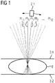
- the 1 shows an exemplary embodiment of the mammography system according to the invention in a first embodiment.
- a plurality of projection data records are recorded at a plurality of projection angles PI -1,0,1,2,...,12 .
- the X-ray source 2.1 is in particular along of a radius around a point in the breast 8, with a projection data set being recorded at each of the projection angles PI ⁇ 1,0,1,2,...,12 .
- the breast 8 of a patient, as the object to be examined is arranged between an upper compression element 3.1 and a lower compression element 3.2.
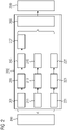
- the 2 shows an exemplary embodiment of the method according to the invention for generating a synthetic mammogram, comprising the steps of recording 200 and generating 210.
- FIG 2 shows in particular a preferred order of steps.
- the recording step a plurality of projection data sets are recorded at a plurality of projection angles.
- the generation step at least one synthetic mammogram is generated with image properties that are essentially equivalent to a conventional digital full-field mammography recording based on a plurality of projection data sets.
- multiple synthetic mammograms are generated for different projection angles.
- an average intensity projection (AIP) based on the plurality of projection data sets is determined as the first image component.
- the average projection corresponds in particular to a projection, particularly preferably the mean projection PI 0 .
- a number of synthetic mammograms are generated, then a number of projections are each used as an average projection, so that a synthetic mammogram is generated for each of these projections.
- the maximum number of synthetic mammograms generated can equal the total number of projections.
- a synthetic mammogram can preferably be generated for 17 of 25 projections, for example.
- At least one of the following steps is applied to the average intensity projection: Intensity adjustment 203, gray value distribution adjustment 205 and/or scattered radiation correction, and lime-preserving noise filter 207.
- the step of generating includes determining 211, 221 a maximum intensity projection (MIP) based on the plurality of projection data sets as the second image component.
- MIP maximum intensity projection
- the maximum intensity projection is broken down into at least two different frequency components.
- the at least two different frequency components include high-frequency components in step 213 and medium-frequency components in step 223 .
- the at least two different frequency components are scaled in steps 215,225.
- the first image component and the second image component are recombined to form the synthetic mammogram.
- the synthetic mammogram has image properties that are essentially equivalent to a conventional digital full-field mammography recording, wherein an imprinting step 209 can include a predefined image impression setting by means of a multi-frequency adjustment, a lookup table application, and/or windowing. An additional post-processing step can also be applied to the synthetic mammogram.
- the 3 shows an exemplary embodiment of the synthetic mammograms according to the invention in comparison to conventional digital full-field mammography recordings, each with a selected predefined image impression setting in a first embodiment.
- Representation 31 shows a conventional digital full-field mammography recording without a predefined image impression setting.
- the illustration 33 shows a synthetic mammogram with image properties that are essentially equivalent to a conventional digital full-field mammography recording without a predefined image impression setting.
- Representation 35 shows a conventional digital full-field mammography recording with a predefined image impression setting the first embodiment, in particular the so-called flavor 0.
- the representation 37 shows a synthetic mammogram with a predefined image impression setting of the first embodiment, in particular the so-called flavor 0.
- the 4 shows an exemplary embodiment of the synthetic mammograms according to the invention in comparison to conventional digital full-field mammography recordings, each with a selected predefined image impression setting in a second embodiment.
- Representation 41 shows a conventional digital full-field mammography recording without a predefined image impression setting.
- the illustration 43 shows a synthetic mammogram with image properties that are essentially equivalent to a conventional digital full-field mammography recording without a predefined image impression setting.
- Representation 45 shows a conventional digital full-field mammography recording with a predefined image impression setting of the second embodiment, in particular the so-called flavor 1.
- Representation 47 shows a synthetic mammogram with a predefined image impression setting of the second embodiment, in particular the so-called flavor 1.
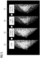
- the figure 5 shows an exemplary embodiment of the synthetic mammograms according to the invention in comparison to conventional digital full-field mammography recordings, each with a selected predefined image impression setting in a third embodiment.
- Representation 51 shows a conventional digital full-field mammography recording without a predefined image impression setting.
- the illustration 53 shows a synthetic mammogram with image properties that are essentially equivalent to a conventional digital full-field mammography recording without a predefined image impression setting.
- the illustration 55 shows a conventional digital full-field mammography recording with a predefined image impression setting of the third embodiment, in particular the so-called Flavor 6.
- Representation 57 shows a synthetic mammogram with a predefined image impression setting of the third embodiment, in particular the so-called Flavor 6.
- the 6 shows an exemplary embodiment of the mammography system 1 according to the invention in a second embodiment.
- the mammography system 1 includes a stand 1.1, on which the x-ray housing 2 having the x-ray source 2.1 and the x-ray detector 5 together with a compression unit 3 are arranged.
- the X-ray housing 2 is rotatably mounted on the stand 1.1 with respect to the stand 1.1 and the X-ray detector 5 and the compression unit 3.
- the compression unit 3 comprises an upper compression element 3.1 and a lower compression element 3.2, between which the breast 8 of a patient is arranged.
- the mammography system 1 is connected to a data processing unit 10 .
- the data processing unit 10 comprises at least one processor unit 10.1, a visualization unit 10.2 and an input unit 10.3.
- the mammography system 1 can be controlled at least partially via a foot switch 1.2.
Claims (13)
- Procédé de production d'un mammogramme synthétique comprenant les stades :- enregistrement (200) d'une pluralité d'ensembles de données de projection sous une pluralité d'angles (PI-1,0,1,2,...,12) de projection,- production (210) d'au moins un mammogramme synthétique ayant une propriété d'image sensiblement équivalente à un enregistrement de mammographie numérique classique à plein champ reposant sur plusieurs ensembles de données de projection,- dans lequel le stade de la production (210) comprend une détermination (201) d'une projection d'intensité moyenne reposant sur la pluralité d'ensembles de données de projection comme première composante d'image, dans lequel on choisit un ensemble de données de projection ou plusieurs ensembles de données de projection,- on applique à la projection d'intensité moyenne au moins l'un des stades suivants :- adaptation (203) d'intensité,- adaptation (205) de la répartition de valeurs de gris,- correction d'anti-diffusion, et- filtrage (207) de bruit conservateur,- le stade de la production (210) comprend une détermination (211, 221) d'une projection d'intensité maximum sur la base de la pluralité d'ensembles de données de projection comme deuxième composante d'image, et- on recombine la première composante d'image et la deuxième composante d'image en le mammogramme synthétique.
- Procédé suivant la revendication 1, comprenant en outre le stade :- estampage (209) d'un réglage d'impression d'image sélectionné défini à l'avance sur le mammogramme synthétique.
- Procédé suivant la revendication 2, dans lequel le réglage d'impression d'image défini à l'avance comprend une adaptation multifréquence, une application de table de consultation ou/et un fenestrage.
- Procédé suivant l'une des revendications précédentes, dans lequel on décompose la projection d'intensité maximum en au moins deux composantes (213, 223) de fréquence différentes.
- Procédé suivant l'une des revendications précédentes, dans lequel les au moins deux composantes de fréquence différentes comprennent des composantes de haute fréquence et des composantes de moyenne fréquence.
- Procédé suivant l'une des revendications 4 ou 5, dans lequel on met à l'échelle (215, 225) les au moins deux composantes de fréquence différentes.
- Procédé suivant l'une des revendications précédentes, dans lequel on applique un stade de traitement ultérieur au mammogramme synthétique.
- Procédé suivant l'une des revendications précédentes, dans lequel on compare le mammogramme synthétique à un enregistrement de mammographie à plein champ numérique antérieure.
- Procédé suivant la revendication 8, dans lequel on choisit le mammogramme synthétique composé de plusieurs mammogrammes synthétiques produits pour la comparaison à un enregistrement de mammographie à plein champ numérique antérieure.
- Procédé suivant l'une des revendications précédentes, dans le mammogramme synthétique comprend des repérages CAD.
- Système (1) de mammographie pour effectuer un procédé suivant l'une des revendications précédentes comportant une unité (1.1, 2.1, 3, 5) d'enregistrement et une unité de production.
- Produit de programme d'ordinateur comprenant un programme d'ordinateur, qui peut être chargé directement dans un dispositif de mémoire d'un dispositif de commande d'un système (1) de mammographie, comprenant des parties de programme pour effectuer tous les stades d'un procédé suivant l'une des revendications 1 à 10, lorsque le programme d'ordinateur est exécuté dans le dispositif de commande du système (1) de mammographie.
- Support, déchiffrable par ordinateur, sur lequel sont mises en mémoire des parties de programme déchiffrables et pouvant être réalisées par une unité informatique, afin d'effectuer tous les stades d'un procédé suivant l'une des revendications 1 à 10, lorsque les parties du programme sont exécutées par l'unité informatique.
Priority Applications (1)
| Application Number | Priority Date | Filing Date | Title |
|---|---|---|---|
| US16/682,388 US11877879B2 (en) | 2018-11-23 | 2019-11-13 | Synthetic mammogram with imprinted image impression |
Applications Claiming Priority (1)
| Application Number | Priority Date | Filing Date | Title |
|---|---|---|---|
| EP18208120 | 2018-11-23 |
Publications (2)
| Publication Number | Publication Date |
|---|---|
| EP3657442A1 EP3657442A1 (fr) | 2020-05-27 |
| EP3657442B1 true EP3657442B1 (fr) | 2022-10-26 |
Family
ID=64476946
Family Applications (1)
| Application Number | Title | Priority Date | Filing Date |
|---|---|---|---|
| EP18214794.2A Active EP3657442B1 (fr) | 2018-11-23 | 2018-12-20 | Mammogramme synthétique à impression estampée d'image |
Country Status (2)
| Country | Link |
|---|---|
| US (1) | US11877879B2 (fr) |
| EP (1) | EP3657442B1 (fr) |
Families Citing this family (3)
| Publication number | Priority date | Publication date | Assignee | Title |
|---|---|---|---|---|
| DE102020212089B3 (de) | 2020-09-25 | 2021-09-16 | Siemens Healthcare Gmbh | Verfahren und Vorrichtung zur Bildentrauschung sowie eine Steuereinrichtung, ein bildgebendes System, ein Computerprogrammprodukt und ein computerlesbares Medium dazu |
| DE102020212382B3 (de) * | 2020-09-30 | 2022-01-20 | Siemens Healthcare Gmbh | Rekonstruktion von Bildern mit Filtermatrizen |
| EP4344644A1 (fr) * | 2022-09-29 | 2024-04-03 | Siemens Healthineers AG | Procédé mis en uvre par ordinateur pour fournir une première image à rayons x et une seconde image à rayons x acquises par un système d'imagerie à rayons x |
Family Cites Families (11)
| Publication number | Priority date | Publication date | Assignee | Title |
|---|---|---|---|---|
| US5704355A (en) * | 1994-07-01 | 1998-01-06 | Bridges; Jack E. | Non-invasive system for breast cancer detection |
| US7760924B2 (en) * | 2002-11-27 | 2010-07-20 | Hologic, Inc. | System and method for generating a 2D image from a tomosynthesis data set |
| JP5528518B2 (ja) * | 2012-09-28 | 2014-06-25 | 富士フイルム株式会社 | 放射線画像生成装置および方法 |
| WO2015130916A1 (fr) * | 2014-02-28 | 2015-09-03 | Hologic, Inc. | Système et procédé de production et d'affichage de dalles d'image de tomosynthèse |
| US9569864B2 (en) | 2014-09-12 | 2017-02-14 | Siemens Aktiengesellschaft | Method and apparatus for projection image generation from tomographic images |
| US9836858B2 (en) * | 2014-09-19 | 2017-12-05 | Siemens Aktiengesellschaft | Method for generating a combined projection image and imaging device |
| JP6766045B2 (ja) * | 2014-11-20 | 2020-10-07 | コーニンクレッカ フィリップス エヌ ヴェKoninklijke Philips N.V. | トモシンセシスデータから合成マンモグラムを生成する方法 |
| US9792703B2 (en) * | 2015-07-06 | 2017-10-17 | Siemens Healthcare Gmbh | Generating a synthetic two-dimensional mammogram |
| JP6502509B2 (ja) * | 2015-09-10 | 2019-04-17 | 富士フイルム株式会社 | 画像処理装置、放射線画像撮影システム、画像処理方法、及び画像処理プログラム |
| JP7169986B2 (ja) * | 2017-03-30 | 2022-11-11 | ホロジック, インコーポレイテッド | オブジェクトグリッド増強を用いて高次元画像データから低次元画像データを合成するためのシステムおよび方法 |
| CN112770674A (zh) * | 2018-09-28 | 2021-05-07 | 豪洛捷公司 | 通过高密度元素抑制来合成乳腺组织的图像生成的系统和方法 |
-
2018
- 2018-12-20 EP EP18214794.2A patent/EP3657442B1/fr active Active
-
2019
- 2019-11-13 US US16/682,388 patent/US11877879B2/en active Active
Also Published As
| Publication number | Publication date |
|---|---|
| EP3657442A1 (fr) | 2020-05-27 |
| US11877879B2 (en) | 2024-01-23 |
| US20200163638A1 (en) | 2020-05-28 |
Similar Documents
| Publication | Publication Date | Title |
|---|---|---|
| DE3826287C2 (de) | Verfahren und Vorrichtung zur automatischen Analyse von Lungengewebe aus einem röntgenologischen Brustbild | |
| DE102008028387B4 (de) | Tomographisches Bildrekonstruktionsverfahren zum Erzeugen eines Bildes von einem Untersuchungsobjekt und nach diesem Verfahren arbeitende bildgebende Einrichtung | |
| DE102009053471B4 (de) | Verfahren und Vorrichtung zur Identifizierung und Zuordnung von Koronarkalk zu einem Herzkranzgefäß sowie Computerprogrammprodukt | |
| DE102011003135B4 (de) | Bildgebungsverfahren zum Rotieren eines Gewebebereichs | |
| DE102007053511A1 (de) | Röntgentomographie-Bildgebungsgerät | |
| EP3657442B1 (fr) | Mammogramme synthétique à impression estampée d'image | |
| DE102007041976A1 (de) | Verfahren zur Erzeugung eines Tomosynthesebildes | |
| DE10353882A1 (de) | Verfahren und Einrichtung zur Weichgewebevolumen-Sichtbarmachung | |
| DE102011003137A1 (de) | Bildgebungsverfahren mit einer verbesserten Darstellung eines Gewebebereichs | |
| DE102006043743A1 (de) | Verfahren und Vorrichtung zur Kombination von Bildern | |
| DE102016219887A1 (de) | Verfahren und System zur Nutzung von Messdaten | |
| DE10229113A1 (de) | Verfahren zur Grauwert-basierten Bildfilterung in der Computer-Tomographie | |
| DE10356174A1 (de) | Verfahren und Einrichtung zur Tomosynthese-Bildverbesserung unter Verwendung von Querfilterung | |
| DE10238322A1 (de) | Retrospektive bzw. fenstergesteuerte Filterung von Bildern zur Adaption von Schärfe und Rauschen in der Computer-Tomographie | |
| DE102011075917B4 (de) | Verfahren zum Bereitstellen eines 3D-Bilddatensatzes mit unterdrückten Messfeldüberschreitungsartefakten und Computertomograph | |
| WO2008052854A1 (fr) | Procédé et module d'affichage d'une image aux rayons x prise dans le cadre d'une mammographie | |
| EP3327673B1 (fr) | Génération d'images ct à haute résolution comportant des informations spectrales | |
| DE102016211766A1 (de) | Erzeugung einer Bildsequenz | |
| DE102018222592A1 (de) | Verfahren zur Artefaktreduzierung in einem medizinischen Bilddatensatz, Röntgeneinrichtung, Computerprogramm und elektronisch lesbarer Datenträger | |
| EP3797698A1 (fr) | Procédé de génération d'un mammogramme synthétique se basant sur une imagerie par tomosynthèse double énergie | |
| DE102009019840A1 (de) | Kontrastverstärkung von CT-Bildern mittels eines Multibandfilters | |
| DE102011003138B4 (de) | Bildgebungsverfahren mit optimierter Grauwertfensterbestimmung | |
| EP2101648B1 (fr) | Procédé et dispositif de formation d'une image radiotomographique de synthèse en 3d | |
| DE102020212382B3 (de) | Rekonstruktion von Bildern mit Filtermatrizen | |
| DE102020209706A1 (de) | Synthetisches Mammogramm mit reduzierter Überlagerung von Gewebeveränderungen |
Legal Events
| Date | Code | Title | Description |
|---|---|---|---|
| PUAI | Public reference made under article 153(3) epc to a published international application that has entered the european phase |
Free format text: ORIGINAL CODE: 0009012 |
|
| STAA | Information on the status of an ep patent application or granted ep patent |
Free format text: STATUS: THE APPLICATION HAS BEEN PUBLISHED |
|
| AK | Designated contracting states |
Kind code of ref document: A1 Designated state(s): AL AT BE BG CH CY CZ DE DK EE ES FI FR GB GR HR HU IE IS IT LI LT LU LV MC MK MT NL NO PL PT RO RS SE SI SK SM TR |
|
| AX | Request for extension of the european patent |
Extension state: BA ME |
|
| STAA | Information on the status of an ep patent application or granted ep patent |
Free format text: STATUS: REQUEST FOR EXAMINATION WAS MADE |
|
| 17P | Request for examination filed |
Effective date: 20201126 |
|
| RBV | Designated contracting states (corrected) |
Designated state(s): AL AT BE BG CH CY CZ DE DK EE ES FI FR GB GR HR HU IE IS IT LI LT LU LV MC MK MT NL NO PL PT RO RS SE SI SK SM TR |
|
| STAA | Information on the status of an ep patent application or granted ep patent |
Free format text: STATUS: EXAMINATION IS IN PROGRESS |
|
| 17Q | First examination report despatched |
Effective date: 20210226 |
|
| STAA | Information on the status of an ep patent application or granted ep patent |
Free format text: STATUS: EXAMINATION IS IN PROGRESS |
|
| GRAP | Despatch of communication of intention to grant a patent |
Free format text: ORIGINAL CODE: EPIDOSNIGR1 |
|
| STAA | Information on the status of an ep patent application or granted ep patent |
Free format text: STATUS: GRANT OF PATENT IS INTENDED |
|
| INTG | Intention to grant announced |
Effective date: 20220623 |
|
| GRAS | Grant fee paid |
Free format text: ORIGINAL CODE: EPIDOSNIGR3 |
|
| GRAA | (expected) grant |
Free format text: ORIGINAL CODE: 0009210 |
|
| STAA | Information on the status of an ep patent application or granted ep patent |
Free format text: STATUS: THE PATENT HAS BEEN GRANTED |
|
| AK | Designated contracting states |
Kind code of ref document: B1 Designated state(s): AL AT BE BG CH CY CZ DE DK EE ES FI FR GB GR HR HU IE IS IT LI LT LU LV MC MK MT NL NO PL PT RO RS SE SI SK SM TR |
|
| REG | Reference to a national code |
Ref country code: GB Ref legal event code: FG4D Free format text: NOT ENGLISH |
|
| REG | Reference to a national code |
Ref country code: CH Ref legal event code: EP |
|
| REG | Reference to a national code |
Ref country code: AT Ref legal event code: REF Ref document number: 1527610 Country of ref document: AT Kind code of ref document: T Effective date: 20221115 |
|
| REG | Reference to a national code |
Ref country code: DE Ref legal event code: R096 Ref document number: 502018010909 Country of ref document: DE |
|
| REG | Reference to a national code |
Ref country code: IE Ref legal event code: FG4D Free format text: LANGUAGE OF EP DOCUMENT: GERMAN |
|
| REG | Reference to a national code |
Ref country code: LT Ref legal event code: MG9D |
|
| REG | Reference to a national code |
Ref country code: NL Ref legal event code: MP Effective date: 20221026 |
|
| PG25 | Lapsed in a contracting state [announced via postgrant information from national office to epo] |
Ref country code: NL Free format text: LAPSE BECAUSE OF FAILURE TO SUBMIT A TRANSLATION OF THE DESCRIPTION OR TO PAY THE FEE WITHIN THE PRESCRIBED TIME-LIMIT Effective date: 20221026 |
|
| PG25 | Lapsed in a contracting state [announced via postgrant information from national office to epo] |
Ref country code: SE Free format text: LAPSE BECAUSE OF FAILURE TO SUBMIT A TRANSLATION OF THE DESCRIPTION OR TO PAY THE FEE WITHIN THE PRESCRIBED TIME-LIMIT Effective date: 20221026 Ref country code: PT Free format text: LAPSE BECAUSE OF FAILURE TO SUBMIT A TRANSLATION OF THE DESCRIPTION OR TO PAY THE FEE WITHIN THE PRESCRIBED TIME-LIMIT Effective date: 20230227 Ref country code: NO Free format text: LAPSE BECAUSE OF FAILURE TO SUBMIT A TRANSLATION OF THE DESCRIPTION OR TO PAY THE FEE WITHIN THE PRESCRIBED TIME-LIMIT Effective date: 20230126 Ref country code: LT Free format text: LAPSE BECAUSE OF FAILURE TO SUBMIT A TRANSLATION OF THE DESCRIPTION OR TO PAY THE FEE WITHIN THE PRESCRIBED TIME-LIMIT Effective date: 20221026 Ref country code: FI Free format text: LAPSE BECAUSE OF FAILURE TO SUBMIT A TRANSLATION OF THE DESCRIPTION OR TO PAY THE FEE WITHIN THE PRESCRIBED TIME-LIMIT Effective date: 20221026 Ref country code: ES Free format text: LAPSE BECAUSE OF FAILURE TO SUBMIT A TRANSLATION OF THE DESCRIPTION OR TO PAY THE FEE WITHIN THE PRESCRIBED TIME-LIMIT Effective date: 20221026 |
|
| PG25 | Lapsed in a contracting state [announced via postgrant information from national office to epo] |
Ref country code: RS Free format text: LAPSE BECAUSE OF FAILURE TO SUBMIT A TRANSLATION OF THE DESCRIPTION OR TO PAY THE FEE WITHIN THE PRESCRIBED TIME-LIMIT Effective date: 20221026 Ref country code: PL Free format text: LAPSE BECAUSE OF FAILURE TO SUBMIT A TRANSLATION OF THE DESCRIPTION OR TO PAY THE FEE WITHIN THE PRESCRIBED TIME-LIMIT Effective date: 20221026 Ref country code: LV Free format text: LAPSE BECAUSE OF FAILURE TO SUBMIT A TRANSLATION OF THE DESCRIPTION OR TO PAY THE FEE WITHIN THE PRESCRIBED TIME-LIMIT Effective date: 20221026 Ref country code: IS Free format text: LAPSE BECAUSE OF FAILURE TO SUBMIT A TRANSLATION OF THE DESCRIPTION OR TO PAY THE FEE WITHIN THE PRESCRIBED TIME-LIMIT Effective date: 20230226 Ref country code: HR Free format text: LAPSE BECAUSE OF FAILURE TO SUBMIT A TRANSLATION OF THE DESCRIPTION OR TO PAY THE FEE WITHIN THE PRESCRIBED TIME-LIMIT Effective date: 20221026 Ref country code: GR Free format text: LAPSE BECAUSE OF FAILURE TO SUBMIT A TRANSLATION OF THE DESCRIPTION OR TO PAY THE FEE WITHIN THE PRESCRIBED TIME-LIMIT Effective date: 20230127 |
|
| PGFP | Annual fee paid to national office [announced via postgrant information from national office to epo] |
Ref country code: GB Payment date: 20230103 Year of fee payment: 5 Ref country code: DE Payment date: 20230217 Year of fee payment: 5 |
|
| REG | Reference to a national code |
Ref country code: DE Ref legal event code: R097 Ref document number: 502018010909 Country of ref document: DE |
|
| PG25 | Lapsed in a contracting state [announced via postgrant information from national office to epo] |
Ref country code: SM Free format text: LAPSE BECAUSE OF FAILURE TO SUBMIT A TRANSLATION OF THE DESCRIPTION OR TO PAY THE FEE WITHIN THE PRESCRIBED TIME-LIMIT Effective date: 20221026 Ref country code: RO Free format text: LAPSE BECAUSE OF FAILURE TO SUBMIT A TRANSLATION OF THE DESCRIPTION OR TO PAY THE FEE WITHIN THE PRESCRIBED TIME-LIMIT Effective date: 20221026 Ref country code: EE Free format text: LAPSE BECAUSE OF FAILURE TO SUBMIT A TRANSLATION OF THE DESCRIPTION OR TO PAY THE FEE WITHIN THE PRESCRIBED TIME-LIMIT Effective date: 20221026 Ref country code: DK Free format text: LAPSE BECAUSE OF FAILURE TO SUBMIT A TRANSLATION OF THE DESCRIPTION OR TO PAY THE FEE WITHIN THE PRESCRIBED TIME-LIMIT Effective date: 20221026 Ref country code: CZ Free format text: LAPSE BECAUSE OF FAILURE TO SUBMIT A TRANSLATION OF THE DESCRIPTION OR TO PAY THE FEE WITHIN THE PRESCRIBED TIME-LIMIT Effective date: 20221026 |
|
| REG | Reference to a national code |
Ref country code: CH Ref legal event code: PL |
|
| REG | Reference to a national code |
Ref country code: BE Ref legal event code: MM Effective date: 20221231 |
|
| PG25 | Lapsed in a contracting state [announced via postgrant information from national office to epo] |
Ref country code: SK Free format text: LAPSE BECAUSE OF FAILURE TO SUBMIT A TRANSLATION OF THE DESCRIPTION OR TO PAY THE FEE WITHIN THE PRESCRIBED TIME-LIMIT Effective date: 20221026 Ref country code: LU Free format text: LAPSE BECAUSE OF NON-PAYMENT OF DUE FEES Effective date: 20221220 Ref country code: AL Free format text: LAPSE BECAUSE OF FAILURE TO SUBMIT A TRANSLATION OF THE DESCRIPTION OR TO PAY THE FEE WITHIN THE PRESCRIBED TIME-LIMIT Effective date: 20221026 |
|
| PLBE | No opposition filed within time limit |
Free format text: ORIGINAL CODE: 0009261 |
|
| STAA | Information on the status of an ep patent application or granted ep patent |
Free format text: STATUS: NO OPPOSITION FILED WITHIN TIME LIMIT |
|
| 26N | No opposition filed |
Effective date: 20230727 |
|
| PG25 | Lapsed in a contracting state [announced via postgrant information from national office to epo] |
Ref country code: LI Free format text: LAPSE BECAUSE OF NON-PAYMENT OF DUE FEES Effective date: 20221231 Ref country code: IE Free format text: LAPSE BECAUSE OF NON-PAYMENT OF DUE FEES Effective date: 20221220 Ref country code: CH Free format text: LAPSE BECAUSE OF NON-PAYMENT OF DUE FEES Effective date: 20221231 |
|
| PG25 | Lapsed in a contracting state [announced via postgrant information from national office to epo] |
Ref country code: SI Free format text: LAPSE BECAUSE OF FAILURE TO SUBMIT A TRANSLATION OF THE DESCRIPTION OR TO PAY THE FEE WITHIN THE PRESCRIBED TIME-LIMIT Effective date: 20221026 Ref country code: BE Free format text: LAPSE BECAUSE OF NON-PAYMENT OF DUE FEES Effective date: 20221231 |
|
| PGFP | Annual fee paid to national office [announced via postgrant information from national office to epo] |
Ref country code: FR Payment date: 20231214 Year of fee payment: 6 |
|
| REG | Reference to a national code |
Ref country code: DE Ref legal event code: R081 Ref document number: 502018010909 Country of ref document: DE Owner name: SIEMENS HEALTHINEERS AG, DE Free format text: FORMER OWNER: SIEMENS HEALTHCARE GMBH, MUENCHEN, DE |
|
| PG25 | Lapsed in a contracting state [announced via postgrant information from national office to epo] |
Ref country code: HU Free format text: LAPSE BECAUSE OF FAILURE TO SUBMIT A TRANSLATION OF THE DESCRIPTION OR TO PAY THE FEE WITHIN THE PRESCRIBED TIME-LIMIT; INVALID AB INITIO Effective date: 20181220 |