EP3656263A1 - Récipient en matière plastique moulée par injection - Google Patents
Récipient en matière plastique moulée par injection Download PDFInfo
- Publication number
- EP3656263A1 EP3656263A1 EP18208098.6A EP18208098A EP3656263A1 EP 3656263 A1 EP3656263 A1 EP 3656263A1 EP 18208098 A EP18208098 A EP 18208098A EP 3656263 A1 EP3656263 A1 EP 3656263A1
- Authority
- EP
- European Patent Office
- Prior art keywords
- container
- shell
- lid
- container lid
- filter
- Prior art date
- Legal status (The legal status is an assumption and is not a legal conclusion. Google has not performed a legal analysis and makes no representation as to the accuracy of the status listed.)
- Granted
Links
- 239000002991 molded plastic Substances 0.000 title claims abstract description 5
- 238000002347 injection Methods 0.000 title abstract description 3
- 239000007924 injection Substances 0.000 title abstract description 3
- 235000013399 edible fruits Nutrition 0.000 claims abstract description 9
- 235000013311 vegetables Nutrition 0.000 claims abstract description 9
- 235000013305 food Nutrition 0.000 claims description 42
- 238000009423 ventilation Methods 0.000 claims description 20
- 238000003780 insertion Methods 0.000 claims 2
- 230000037431 insertion Effects 0.000 claims 2
- 230000002441 reversible effect Effects 0.000 claims 1
- XLYOFNOQVPJJNP-UHFFFAOYSA-N water Substances O XLYOFNOQVPJJNP-UHFFFAOYSA-N 0.000 description 50
- 239000003570 air Substances 0.000 description 25
- 230000005494 condensation Effects 0.000 description 21
- 238000009833 condensation Methods 0.000 description 21
- 230000015572 biosynthetic process Effects 0.000 description 14
- VGGSQFUCUMXWEO-UHFFFAOYSA-N Ethene Chemical compound C=C VGGSQFUCUMXWEO-UHFFFAOYSA-N 0.000 description 11
- NUJOXMJBOLGQSY-UHFFFAOYSA-N manganese dioxide Chemical compound O=[Mn]=O NUJOXMJBOLGQSY-UHFFFAOYSA-N 0.000 description 10
- 238000004519 manufacturing process Methods 0.000 description 7
- OKTJSMMVPCPJKN-UHFFFAOYSA-N Carbon Chemical compound [C] OKTJSMMVPCPJKN-UHFFFAOYSA-N 0.000 description 6
- 235000012055 fruits and vegetables Nutrition 0.000 description 6
- 239000004033 plastic Substances 0.000 description 6
- 229920003023 plastic Polymers 0.000 description 6
- 238000001746 injection moulding Methods 0.000 description 5
- 239000000463 material Substances 0.000 description 5
- 241000894006 Bacteria Species 0.000 description 4
- 239000000853 adhesive Substances 0.000 description 4
- 230000001070 adhesive effect Effects 0.000 description 4
- 239000010457 zeolite Substances 0.000 description 4
- 238000010521 absorption reaction Methods 0.000 description 3
- 239000012080 ambient air Substances 0.000 description 3
- 230000000295 complement effect Effects 0.000 description 3
- 238000011161 development Methods 0.000 description 3
- 230000018109 developmental process Effects 0.000 description 3
- 230000000694 effects Effects 0.000 description 3
- 230000003647 oxidation Effects 0.000 description 3
- 238000007254 oxidation reaction Methods 0.000 description 3
- 230000008092 positive effect Effects 0.000 description 3
- 230000002028 premature Effects 0.000 description 3
- 239000006096 absorbing agent Substances 0.000 description 2
- 150000001875 compounds Chemical class 0.000 description 2
- 230000007613 environmental effect Effects 0.000 description 2
- 238000004880 explosion Methods 0.000 description 2
- 230000002209 hydrophobic effect Effects 0.000 description 2
- 230000001590 oxidative effect Effects 0.000 description 2
- 239000012286 potassium permanganate Substances 0.000 description 2
- 230000005070 ripening Effects 0.000 description 2
- 238000009736 wetting Methods 0.000 description 2
- 239000004743 Polypropylene Substances 0.000 description 1
- 229910000323 aluminium silicate Inorganic materials 0.000 description 1
- 230000037237 body shape Effects 0.000 description 1
- 235000021268 hot food Nutrition 0.000 description 1
- 150000002430 hydrocarbons Chemical class 0.000 description 1
- 230000007774 longterm Effects 0.000 description 1
- 239000011049 pearl Substances 0.000 description 1
- 229930195732 phytohormone Natural products 0.000 description 1
- 239000003375 plant hormone Substances 0.000 description 1
- -1 polypropylene Polymers 0.000 description 1
- 229920001155 polypropylene Polymers 0.000 description 1
- 239000011148 porous material Substances 0.000 description 1
- 239000002244 precipitate Substances 0.000 description 1
- 239000000047 product Substances 0.000 description 1
- 239000005871 repellent Substances 0.000 description 1
- 230000035943 smell Effects 0.000 description 1
Images


Classifications
-
- B—PERFORMING OPERATIONS; TRANSPORTING
- B65—CONVEYING; PACKING; STORING; HANDLING THIN OR FILAMENTARY MATERIAL
- B65D—CONTAINERS FOR STORAGE OR TRANSPORT OF ARTICLES OR MATERIALS, e.g. BAGS, BARRELS, BOTTLES, BOXES, CANS, CARTONS, CRATES, DRUMS, JARS, TANKS, HOPPERS, FORWARDING CONTAINERS; ACCESSORIES, CLOSURES, OR FITTINGS THEREFOR; PACKAGING ELEMENTS; PACKAGES
- B65D1/00—Containers having bodies formed in one piece, e.g. by casting metallic material, by moulding plastics, by blowing vitreous material, by throwing ceramic material, by moulding pulped fibrous material, by deep-drawing operations performed on sheet material
- B65D1/22—Boxes or like containers with side walls of substantial depth for enclosing contents
-
- A—HUMAN NECESSITIES
- A47—FURNITURE; DOMESTIC ARTICLES OR APPLIANCES; COFFEE MILLS; SPICE MILLS; SUCTION CLEANERS IN GENERAL
- A47J—KITCHEN EQUIPMENT; COFFEE MILLS; SPICE MILLS; APPARATUS FOR MAKING BEVERAGES
- A47J47/00—Kitchen containers, stands or the like, not provided for in other groups of this subclass; Cutting-boards, e.g. for bread
- A47J47/02—Closed containers for foodstuffs
- A47J47/08—Closed containers for foodstuffs for non-granulated foodstuffs
- A47J47/10—Closed containers for foodstuffs for non-granulated foodstuffs with arrangements for keeping fresh
-
- B—PERFORMING OPERATIONS; TRANSPORTING
- B65—CONVEYING; PACKING; STORING; HANDLING THIN OR FILAMENTARY MATERIAL
- B65D—CONTAINERS FOR STORAGE OR TRANSPORT OF ARTICLES OR MATERIALS, e.g. BAGS, BARRELS, BOTTLES, BOXES, CANS, CARTONS, CRATES, DRUMS, JARS, TANKS, HOPPERS, FORWARDING CONTAINERS; ACCESSORIES, CLOSURES, OR FITTINGS THEREFOR; PACKAGING ELEMENTS; PACKAGES
- B65D43/00—Lids or covers for rigid or semi-rigid containers
- B65D43/02—Removable lids or covers
- B65D43/0202—Removable lids or covers without integral tamper element
- B65D43/0214—Removable lids or covers without integral tamper element secured only by friction or gravity
- B65D43/022—Removable lids or covers without integral tamper element secured only by friction or gravity only on the inside, or a part turned to the inside, of the mouth of the container
-
- B—PERFORMING OPERATIONS; TRANSPORTING
- B65—CONVEYING; PACKING; STORING; HANDLING THIN OR FILAMENTARY MATERIAL
- B65D—CONTAINERS FOR STORAGE OR TRANSPORT OF ARTICLES OR MATERIALS, e.g. BAGS, BARRELS, BOTTLES, BOXES, CANS, CARTONS, CRATES, DRUMS, JARS, TANKS, HOPPERS, FORWARDING CONTAINERS; ACCESSORIES, CLOSURES, OR FITTINGS THEREFOR; PACKAGING ELEMENTS; PACKAGES
- B65D21/00—Nestable, stackable or joinable containers; Containers of variable capacity
- B65D21/02—Containers specially shaped, or provided with fittings or attachments, to facilitate nesting, stacking, or joining together
- B65D21/0233—Nestable containers
-
- B—PERFORMING OPERATIONS; TRANSPORTING
- B65—CONVEYING; PACKING; STORING; HANDLING THIN OR FILAMENTARY MATERIAL
- B65D—CONTAINERS FOR STORAGE OR TRANSPORT OF ARTICLES OR MATERIALS, e.g. BAGS, BARRELS, BOTTLES, BOXES, CANS, CARTONS, CRATES, DRUMS, JARS, TANKS, HOPPERS, FORWARDING CONTAINERS; ACCESSORIES, CLOSURES, OR FITTINGS THEREFOR; PACKAGING ELEMENTS; PACKAGES
- B65D2205/00—Venting means
- B65D2205/02—Venting holes
-
- B—PERFORMING OPERATIONS; TRANSPORTING
- B65—CONVEYING; PACKING; STORING; HANDLING THIN OR FILAMENTARY MATERIAL
- B65D—CONTAINERS FOR STORAGE OR TRANSPORT OF ARTICLES OR MATERIALS, e.g. BAGS, BARRELS, BOTTLES, BOXES, CANS, CARTONS, CRATES, DRUMS, JARS, TANKS, HOPPERS, FORWARDING CONTAINERS; ACCESSORIES, CLOSURES, OR FITTINGS THEREFOR; PACKAGING ELEMENTS; PACKAGES
- B65D2543/00—Lids or covers essentially for box-like containers
- B65D2543/00009—Details of lids or covers for rigid or semi-rigid containers
- B65D2543/00018—Overall construction of the lid
- B65D2543/00064—Shape of the outer periphery
- B65D2543/0012—Shape of the outer periphery having straight sides, e.g. with curved corners
- B65D2543/00175—Shape of the outer periphery having straight sides, e.g. with curved corners four straight sides, e.g. trapezium or diamond
- B65D2543/00194—Shape of the outer periphery having straight sides, e.g. with curved corners four straight sides, e.g. trapezium or diamond square or rectangular
-
- B—PERFORMING OPERATIONS; TRANSPORTING
- B65—CONVEYING; PACKING; STORING; HANDLING THIN OR FILAMENTARY MATERIAL
- B65D—CONTAINERS FOR STORAGE OR TRANSPORT OF ARTICLES OR MATERIALS, e.g. BAGS, BARRELS, BOTTLES, BOXES, CANS, CARTONS, CRATES, DRUMS, JARS, TANKS, HOPPERS, FORWARDING CONTAINERS; ACCESSORIES, CLOSURES, OR FITTINGS THEREFOR; PACKAGING ELEMENTS; PACKAGES
- B65D2543/00—Lids or covers essentially for box-like containers
- B65D2543/00009—Details of lids or covers for rigid or semi-rigid containers
- B65D2543/00018—Overall construction of the lid
- B65D2543/00259—Materials used
- B65D2543/00296—Plastic
-
- B—PERFORMING OPERATIONS; TRANSPORTING
- B65—CONVEYING; PACKING; STORING; HANDLING THIN OR FILAMENTARY MATERIAL
- B65D—CONTAINERS FOR STORAGE OR TRANSPORT OF ARTICLES OR MATERIALS, e.g. BAGS, BARRELS, BOTTLES, BOXES, CANS, CARTONS, CRATES, DRUMS, JARS, TANKS, HOPPERS, FORWARDING CONTAINERS; ACCESSORIES, CLOSURES, OR FITTINGS THEREFOR; PACKAGING ELEMENTS; PACKAGES
- B65D85/00—Containers, packaging elements or packages, specially adapted for particular articles or materials
- B65D85/30—Containers, packaging elements or packages, specially adapted for particular articles or materials for articles particularly sensitive to damage by shock or pressure
- B65D85/34—Containers, packaging elements or packages, specially adapted for particular articles or materials for articles particularly sensitive to damage by shock or pressure for fruit, e.g. apples, oranges or tomatoes
Definitions
- the present invention relates to a container made of injection-molded plastic, in particular for storing fruit, vegetables or other foods, according to the preamble of patent claim 1.
- a container made of injection-molded plastic, in particular for storing fruit, vegetables or other foods, according to the preamble of patent claim 1.
- Such a container comprises a bowl with a bowl bottom, a side wall, an essentially circumferential, upper bowl edge and one Container lid.
- This container lid is used for at least partially closing a shell opening which is circumscribed by the edge of the shell.
- Containers of this type have long been known in multiple designs. They are used, for example, to store fruit, vegetables or other foods in the refrigerator or at room temperature. For this purpose, these foods are placed or filled through the tray opening into an inner region of the tray, after which the tray opening is partially or completely closed with the container lid. This protects the food from environmental influences while it is being stored.
- the present invention is therefore based on the object of improving a container of the type mentioned at the outset by means of an optimized storage capacity for fruit, vegetables and other foods.
- a container according to the invention made of injection-molded plastic which is designed in particular for storing fruit, vegetables or other foods, comprises a bowl with a bowl bottom, a side wall and an essentially circumferential, upper bowl edge, which forms a bowl opening, and a container lid for at least partially Closing the shell opening. It is essential with the container according to the invention that the container lid has a three-dimensional surface structure on an inside facing the inner region of the shell. This three-dimensional surface structure is formed by a plurality of adjoining hollow bodies, the basic shape of which comprises a base surface, a cover surface and a jacket surface connecting the base surface and the cover surface.
- These hollow bodies are arranged in such a way that the base surface is located on the container lid, while the cover surface is oriented toward the inner region of the shell.
- the base surface of the hollow body is formed in each case by the container lid, while the cover surface is at least partially open, but preferably not material at all is.
- the outer surface is materially shaped by additional plastic material during injection molding.
- Fruit, vegetables or other foods can be placed or filled into the inner region of the bowl by a user of the container for storage.
- the container lid By at least partially closing the shell opening by means of the container lid, the foodstuffs stored in the inner region of the shell can be protected against environmental influences.
- Such an at least partial closure of the shell opening is to be understood to mean that the container lid either completely covers or closes the shell opening, or that it leaves or does not cover a partial region of the shell opening, as a result of which, for example, food is removed from the inner region of the shell or filled into the inner region can be.
- the container lid can, for example, be designed as an attachment lid which can be placed on the edge of the shell or inserted into this edge of the shell.
- the container lid is designed as a hinged lid which is fastened on one side to the edge of the shell with a hinge element and can be closed.
- the invention is not limited to this.
- the drops of condensed water can precipitate in the area of the outer surface and the base surface of the hollow body by the air containing moisture into one Interior of the hollow body enters.
- Individual condensation water drops formed during the condensation can then not only form a contact point with the plastic surface of the container lid, as in the case of an unstructured, essentially flat container lid according to the prior art. Rather, according to the invention, the condensed water drops can form a plurality of contact points with the lateral surface and / or the base surface of the hollow body.
- the three-dimensional surface structure therefore leads to an improved shelf life of the container according to the invention for foodstuffs compared to the containers known from the prior art.
- the dimensions of the hollow bodies which form the three-dimensional surface structure according to the invention must be selected in such a way that drops of condensed water are actually held in the hollow bodies.
- This can mean the volume of the hollow body to adapt to the typical dimensions of a drop of condensed water, that is to say about 40 to 50 microliters, so that it essentially receives contact on all sides within the hollow body with the outer surface of the hollow body and the contact area between the condensed water drops and the material of the three-dimensional surface structure is increased in such a way that the drop of condensed water is held within the hollow body.
- the hollow body is formed with a polygonal base and cover surface and the outer surface accordingly forms corner regions, it may be sufficient if a drop of condensed water in such a corner region comes into contact with two sides of the outer surface and the base surface of the hollow body in order to be held within the hollow body .
- a hollow body can then possibly also be of significantly larger volume than the volume of a typical drop of condensed water.
- volume of the hollow body is made smaller than typical volumes of condensed water drops, e.g. 30 to 40 microliters, a positive effect can result from the fact that the formation of larger drops of condensation, which could fall down more easily due to their weight, is prevented or made more difficult.
- a first advantageous embodiment of the container according to the invention essentially all hollow bodies are delimited by their outer surface and separated from adjacent hollow bodies. This means that a hollow body shares its outer surface with the neighboring hollow bodies or with the hollow bodies arranged around it. As a result, the lateral surface between the cavities of the hollow body forms webs.
- the base and / or the top surface of the hollow body are polygonal, elliptical or circular.
- the base area and / or the cover area have a number of corner points n, which are connected by an identical number of lines m.
- the corner regions of the lateral surface formed in this way can allow at least two contact surfaces to be formed between the condensed water drop and these corner regions of the lateral surface. If, for example, the condensation water drop has a similar size compared to the size of the base area, a higher number of contact areas can also be formed between the condensation water drop and the hollow body.
- the three-dimensional surface structure can be designed in the form of a honeycomb structure on the side of the container lid facing the inner region of the shell. This means that the three-dimensional surface structure can preferably be designed as an imitation of a honeycomb structure occurring in nature. As is known, this optimizes the relationship between the sum of the volumes of the hollow bodies and the plastic material required for the lateral surfaces formed as webs.
- the lateral surface delimiting the hollow body can preferably have a web width that is significantly smaller than that of a diameter of the hollow body. This can minimize or even prevent the formation of condensation water drops on the end faces of the webs. Since the condensation water drops on the end faces of the webs can only form one or a few contact points with the surface of the container lid, this would ultimately cause the condensation water to drip off or drip from the webs onto the foodstuffs stored in the inner region of the bowl.
- a small web width of the lateral surface delimiting the hollow body further improves the shelf life of the container for food and, moreover, reduces the amount of material required for the three-dimensional structure according to the invention.
- the inside of the container lid is either three-dimensionally structured completely or only partially with hollow bodies.
- the number of hollow bodies correlates with the amount or volume of condensed water that can be held in the area of the honeycomb structure. Since the diameter of the hollow body or its extent correlates with its ability to bind the condensate drops, the hollow bodies in a preferred development of the container have a minimum clear width of 4 to 5 mm, particularly preferably 4.45 to 4.55 mm.
- the hollow bodies are preferably provided with a depth of 1.5 to 2.5 mm, particularly preferably 1.8 to 2.0 mm.
- the base area and the top area are essentially congruent or congruent with one another. Slight deviations of this congruent design of the base area and the top area can be production-related.
- the base area can have a slightly smaller dimension compared to the top surface, which creates a conical shape of the hollow body, which is advantageous when the injection-molded container lid is removed from the mold.
- the container lid has at least one ventilation opening in a further advantageous embodiment. If, for example, hot food is poured into the inner area of the bowl, the bowl opening is completely closed with the container lid and the container is then placed in the refrigerator, the food can be cooled down to a negative pressure in the inner area of the bowl. This makes it difficult for a user to open the container later. A lack of air exchange can also lead to the formation of unpleasant smells and premature spoilage of the food.
- the at least one ventilation opening thus increases the manageability of the container and further improves its shelf life for food. It is within the scope of the invention that the container lid can also have a plurality of ventilation openings.
- the at least one ventilation opening is arranged in the region of the three-dimensional surface structures.
- a ventilation opening can preferably have an identical diameter as a top surface of the basic hollow body shape.
- Ethene is a gaseous hydrocarbon compound (C 2 H 4 ) that acts as a phytohormone or plant hormone in plants. For example, it ripens neighboring fruits and vegetables.
- C 2 H 4 gaseous hydrocarbon compound
- a replaceable filter is therefore arranged on the container lid in a further advantageous embodiment of the container according to the invention, which filter essentially completely covers the at least one ventilation opening.
- This filter can serve for the absorption and / or oxidation of ethene or other gaseous compounds and, for example, activated carbon or an ethene absorber based on manganese dioxide (MnO 2 ) -coated Zeolites or potassium permanganate (KMnO 4 ).
- MnO 2 manganese dioxide
- zeolites are crystalline and porous aluminosilicates which are coated with manganese dioxide.
- the manganese dioxide and the potassium permanganate can cause an oxidation of the gaseous ethene, as a result of which it loses its ripening effect on neighboring fruits or vegetables.
- the products formed during the oxidation can be embedded in the pores of the zeolites or absorbed by them. The filter thus optimizes the shelf life of the container for fruit and vegetables.
- the filter is arranged on an outside of the container lid facing away from the inner region of the shell.
- the air containing the ethene can first pass through the at least one ventilation opening and then be absorbed by the filter.
- the ethene can then be absorbed by the activated carbon or oxidized by the manganese dioxide.
- air from the container environment can pass through the filter and pass through the at least one ventilation opening before it enters the interior of the bowl. Ultimately, this ensures optimal air exchange between the surroundings of the container and the interior of the shell and minimizes the ethene concentration. This has a positive effect on the shelf life of the container for food.
- the filter described above usually has only a limited absorption capacity and / or a limited oxidizing capacity for ethene or other gaseous compounds and must therefore be replaced by a user at regular intervals.
- at least one filter cap is detachably arranged on the container lid in a further advantageous embodiment of the container according to the invention.
- this filter cap preferably comprises at least one latching means, which enables the filter cap to be temporarily fixed to the container lid.
- the filter cap enables the use of interchangeable filters, which do not have to have an additional filter holder. Ultimately, this has a positive effect on the manufacturability and the production costs of these filters and thus of the container.
- the filter cap has at least one air outlet so that the previously described air exchange between the interior of the container and the container surroundings is not impeded by the filter cap.
- the container lid has a recess in which recess the filter can be arranged.
- the depression is preferably arranged in the region of the three-dimensional surface structure. If the depression is on a side substantially opposite the three-dimensional surface structure, i.e. on the outside of the container lid, the filter can be inserted or inserted into the recess in such a way that it is essentially flush with a container lid surface and does not protrude. This arrangement of the filter in the recess, which is flush with the surface of the container lid, makes it easier to stack several containers on top of one another.
- the depression preferably has a frame-like border.
- the filter can be inserted into and removed from this frame-like enclosure.
- This frame-like frame enables the filter to be inserted precisely and thus prevents the filter from sliding sideways in the recess. It is within the scope of the invention that this frame-like border is either closed at the circumference or at least has an interruption in its scope.
- the container lid essentially consists of a lid base and an apron which runs around the edge thereof, the three-dimensional surface structure being arranged in the region of the lid base.
- the shell opening can either be closed by the container lid in such a way that it is inserted into the shell opening and the apron is thereby surrounded by the upper edge of the shell, or in such a way that the apron essentially encloses the upper shell edge when it is put on.
- the container lid is thus designed as a slip lid.
- the depression can extend essentially beyond the lid base and / or the apron. This allows filters with different dimensions to be used.
- the cross section of the filter cap is essentially U-shaped with a first leg and a second leg for placement on the apron of the container lid and a web connecting these legs, the filter cap being insertable into the recess in this way that it substantially completely covers the depression, the frame-like border of the depression and the filter arranged in the frame-like border.
- the filter can be essentially completely covered by the web of the filter cap.
- the locking means described above can preferably be arranged in the region of the two legs and snap into undercuts in the apron of the container lid that are complementary thereto.
- the air passage is arranged in a further advantageous embodiment of the container according to the invention in the region of the first and / or the second leg of the filter cap and is preferably slit-like. Especially when stacking several containers An air exchange between the inner area of the shell and the environment can take place one above the other.
- the container has at least one basket insert which can be inserted into and removed from the inner region of the shell.
- This basket insert makes it easier to insert or remove food into or out of the interior of the container. If the absorption capacity of the three-dimensional surface structure is not sufficient for condensed water and therefore the water that drips off and drips off collects in the area of the container bottom, the food stored in the basket insert does not come into contact with this condensed water. Above all, however, the problem with food containers of the present type is that condensation can form not only on the inside of the container lid, but also inside the bowl, i.e. especially on the side wall.
- a basket insert prevents the food stored in the container from coming into contact with any condensation water formed on the side wall of the bowl. Last but not least, the basket insert prevents the food from lying directly on the bottom of the bowl. Because this can be very disadvantageous, since there is a risk that condensation water formed on the shell wall runs off to the shell bottom and possibly collects there.
- the combination of the three-dimensional surface structure according to the invention of the inside of the container lid with the preferably present basket insert effectively prevents food stored in the container from coming into contact with or remaining in contact with any condensed water, which is preferably on the inside of the container lid and on the side wall of the bowl forms and if necessary collects on the bottom of the bowl.
- this basket insert can preferably have at least one handle. This handle can be gripped by the user to remove the basket insert from the inside of the bowl.
- the basket insert is designed as a sieve.
- Food that is in the sieve can first be washed by the user, after which the sieve can be inserted into the interior of the bowl.
- any condensed water formed on the food can run out through the sieve openings, so that the food does not have long-term contact with the condensed water.
- Figure 1 shows an exploded view of an embodiment of a container 1 designed according to the invention, which has a shell 2, a basket insert 3, a container lid 4, a filter 5 and a filter cap 6.
- a container 1 designed according to the invention, which has a shell 2, a basket insert 3, a container lid 4, a filter 5 and a filter cap 6.
- all components of the container 1 according to the invention are designed as injection molded parts made of polypropylene.
- the shell 2 comprises a shell bottom 21 and a circumferential side wall 22 which is delimited by a circumferential, upper shell edge 23.
- the shell edge 23 encloses a shell opening 24.
- the basket insert 3 can be inserted into an inner region 25 of the shell 2 through this shell opening 24. In the absence of the basket insert 3, fruit, vegetables or other foods can also be filled or inserted directly into this inner region 25 of the shell 2.
- the upper shell edge 23 has a larger diameter than the shell base 21. Since the shell edge 23 and the shell base 21 are connected to one another by the side wall 22, the shell 2 thus has a conical shape.
- This conical shape of the shell 2 results from the production of the shell 2 by the injection molding process and has the advantage that when storing several such containers 1, individual shells 2 can be placed one inside the other. This nestability of several trays 2 leads to a significantly smaller space requirement when storing the containers 1.
- the basket insert 3 has a smaller dimension than the shell 2, so that the basket insert 3 can be inserted into the inner region 25 of the shell 2.
- the basket insert 3 comprises a basket insert base 31, a basket insert wall 32 and an upper, circumferential basket insert edge 33.
- two handles 34, 35 arranged essentially opposite one another are arranged, which are injection-molded in one piece with the upper one Basket insert edge 33 were formed.
- the basket insert 3 is designed as a sieve and therefore has a multiplicity of slot-like sieve openings 36, 37, 38 on. Due to the production of the basket insert 3 using the injection molding process, this also has an essentially conical shape.
- the container lid 4 serves to close the shell opening 24.
- the container lid 4 comprises an essentially circumferential apron 41 and a lid base 42 and is designed as a slip lid.
- the container lid 4 can be placed on the upper shell edge 23 of the shell 2 in such a way that its apron 41 essentially encloses the upper shell edge 23.
- the side wall 22 of the shell 2 has a circumferential projection 26, on which the apron 41 can be placed.
- the filter 5 is essentially cuboid and has an ethene absorber based on activated carbon or zeolites coated with manganese dioxide.
- the container lid 4 in the present exemplary embodiment has a recess 43 with a frame-like border 44 formed therein. The recess 43 extends over the lid base 42 and partly over the apron 41.
- the filter 5 can be inserted into the frame-like surround 44 by a user in a substantially precise manner.
- the frame-like bezel 44 prevents the filter 5 from sliding sideways in the depression 43.
- the filter cap 6 is inserted into the depression in this way 43 that it covers the recess 43, the frame-like casing 44 and the filter 5 arranged in the frame-like casing 44 essentially completely (see also Figure 4 ).
- the filter cap 6 is essentially U-shaped in cross section with a first leg 61, a second leg 62 and a web 63 connecting these legs 61, 62.
- the filter cap 6 can be detachably arranged in the recess 43, in the region of the two legs 61, 62, latching means 64, 65 arranged.
- the latching means 64, 65 snap into undercuts which are complementary thereto in the region of the recess (in Figure 1 not shown, see Figure 4 ).
- the filter cap 6 has a plurality of slot-shaped air passages 66, 67, which ensure an air exchange between the inner region 25 of the shell 2 and the container environment.
- Figure 2 shows a perspective view of the container lid 4 of the embodiment Figure 1 from underneath.
- the container bottom 42 has a three-dimensional surface structure 45 on a side opposite the recess 43, ie on the inside facing the inner region 25 of the shell 2.
- This three-dimensional surface structure 45 is designed as a plurality of mutually adjacent hollow bodies 451 with a base surface 452 arranged on the container lid, a cover surface 453 oriented in the direction of the inner region of the shell 2, and a jacket surface 454 connecting the base surface 452 and the cover surface 453 to one another.
- the top surface 453 is open in each case.
- the base surface 452 and the top surface 453 are essentially congruent, ie aligned with one another.
- all hollow bodies 451 are delimited by their outer surface 454 and separated from adjacent hollow bodies 451.
- honeycomb structure as a three-dimensional surface structure 45. This means that the three-dimensional surface structure 45 of the container lid 4 is imitated by a honeycomb.
- condensation water drops can be deposited in the area of the outer surface 454 and the base surface 452 of the hollow bodies 451 by the air containing the moisture entering the interior of the hollow bodies 451 through the cover surface 453.
- the side of the container bottom 42 facing the inner region 25 of the shell 2 is essentially completely covered with the three-dimensional surface structure 45.
- the hollow bodies 451 have a smallest clear width, that is to say a spacing of 4.511 mm between two parallel sections of the lateral surface 454 which are opposite each other in parallel.
- the depth of the hollow bodies 451, that is to say the web height of the lateral surfaces 454, is 1.9 mm, which results in a volume of the hollow bodies 451 of approximately 34 microliters. This corresponds to a small drop (a Standard drops in pharmacy contain 50 microliters), so that the formation of larger drops of condensed water is difficult. This also promotes the formation of a vacuum under a drop that wants to detach.
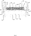
- FIG 3 shows a detail of the embodiment Figure 1 in partial explosion and sectional view.
- the basket insert 3 is in this Figure 2 can be seen in its state inserted into the inner region 25 of the shell 2.
- the basket insert 3 has a smaller dimension than the shell 2 or its inner region 25.
- a distance is maintained between the basket insert wall 32 and the side wall 22 of the shell 2.
- This has the advantage that the basket insert 3 and the food stored therein do not come into contact with condensed water, which may also be deposited in the region of the side wall 22 of the shell 2.
- bacteria and mold formation on the foods stored in the basket insert 3 can be further reduced or even completely prevented.
- the lid base 42 has a plurality of ventilation openings 46, 47 in the area of the frame-like border 44. As already mentioned above, these ventilation openings 46, 47 enable air to be exchanged between the inner region 25 of the shell 2 and the surroundings of the container. In the present exemplary embodiment, these ventilation openings 46, 47 are arranged corresponding to base areas 452 of hollow bodies 451.
- the air can escape from the inner region 25 of the shell 2 first through the hollow bodies 451 and then through the ventilation openings 46, 47.
- the number of ventilation openings 46, 47 is less than the number of hollow bodies 451.
- FIG 4 shows a further detail of the embodiment Figure 1 in sectional view.
- the filter 5 is inserted or inserted into the frame-like surround 44 of the container lid 4.
- the filter 5 covers all ventilation openings 46, 47, which are arranged in the region of the frame-like surround 44 of the lid base 42.
- the filter 5 By inserting the filter 5 into the frame-like casing 44, the filter is held by this casing 44 in such a way that the filter 5 is protected against slipping sideways in the region of the recess 43 of the container lid 4.
- the filter cap 6 is inserted into the recess 43 in such a way that the latching means 64, 65 designed as latching lugs are latched into undercuts of the container lid that are complementary to this.
- the filter 5 is thereby sandwiched between the lid base 42 in the area of the frame-like border 44 and the web 63 of the filter cap 6.
- the filter 5 is thereby secured against falling out of the frame-like casing 44 in the vertical direction.
- Figure 5 shows an external view of the embodiment Figure 1 in perspective.
- Figure 5 shows that the filter cap 6, when inserted into the recess 43, is flush with the surface of the container lid 4.
- This flush arrangement of the filter cap 6 enables an unimpeded stacking of several containers 1 on top of one another.
- the Container lid 4 has two recesses 48, 49 in the region of the apron 41. By engaging in these two recesses 48, 49, he can easily remove the container lid 4 from the upper edge 23 of the shell 2 without an additional handle having to be arranged on the container lid 4.
Landscapes
- Engineering & Computer Science (AREA)
- Mechanical Engineering (AREA)
- Ceramic Engineering (AREA)
- Food Science & Technology (AREA)
- Packages (AREA)
- Packging For Living Organisms, Food Or Medicinal Products That Are Sensitive To Environmental Conditiond (AREA)
- Closures For Containers (AREA)
Priority Applications (3)
| Application Number | Priority Date | Filing Date | Title |
|---|---|---|---|
| EP18208098.6A EP3656263B1 (fr) | 2018-11-23 | 2018-11-23 | Récipient en matière plastique moulée par injection |
| PL18208098T PL3656263T3 (pl) | 2018-11-23 | 2018-11-23 | Pojemnik z tworzywa sztucznego formowanego wtryskowo |
| US16/683,653 US11407549B2 (en) | 2018-11-23 | 2019-11-14 | Container made of injection molded plastic |
Applications Claiming Priority (1)
| Application Number | Priority Date | Filing Date | Title |
|---|---|---|---|
| EP18208098.6A EP3656263B1 (fr) | 2018-11-23 | 2018-11-23 | Récipient en matière plastique moulée par injection |
Publications (2)
| Publication Number | Publication Date |
|---|---|
| EP3656263A1 true EP3656263A1 (fr) | 2020-05-27 |
| EP3656263B1 EP3656263B1 (fr) | 2021-01-06 |
Family
ID=64456871
Family Applications (1)
| Application Number | Title | Priority Date | Filing Date |
|---|---|---|---|
| EP18208098.6A Active EP3656263B1 (fr) | 2018-11-23 | 2018-11-23 | Récipient en matière plastique moulée par injection |
Country Status (3)
| Country | Link |
|---|---|
| US (1) | US11407549B2 (fr) |
| EP (1) | EP3656263B1 (fr) |
| PL (1) | PL3656263T3 (fr) |
Families Citing this family (4)
| Publication number | Priority date | Publication date | Assignee | Title |
|---|---|---|---|---|
| US11649103B2 (en) | 2021-02-15 | 2023-05-16 | Sonoco Development, Inc. | Tray with removable insert |
| USD1027448S1 (en) * | 2022-01-04 | 2024-05-21 | Ningbo Lisi Houseware Co., Ltd. | Filterable preservation box |
| USD1041170S1 (en) * | 2022-03-30 | 2024-09-10 | Ningbo Lisi Houseware Co., Ltd. | Filterable preservation box |
| USD1026462S1 (en) * | 2022-03-30 | 2024-05-14 | Ningbo Lisi Houseware Co., Ltd. | Filterable preservation box |
Citations (3)
| Publication number | Priority date | Publication date | Assignee | Title |
|---|---|---|---|---|
| US20040011794A1 (en) * | 2002-04-19 | 2004-01-22 | Ross Heil | Food preservation container and filter |
| US20120241450A1 (en) * | 2009-11-20 | 2012-09-27 | Valspar Sourcimg ,Inc. | Anti-skinning container interior portion |
| DE202016104490U1 (de) * | 2016-08-15 | 2016-09-15 | Rotho Kunststoff Ag | Behälter aus Kunststoff |
Family Cites Families (3)
| Publication number | Priority date | Publication date | Assignee | Title |
|---|---|---|---|---|
| US10292534B2 (en) * | 2017-01-12 | 2019-05-21 | Frederick Fox, III | Food container assembly |
| US10442590B2 (en) * | 2017-08-24 | 2019-10-15 | Rubbermaid Commercial Products Llc | Container filtration systems |
| US20190084756A1 (en) * | 2017-09-19 | 2019-03-21 | Rubbermaid Incorporated | Container with gas and/or liquid permeable membrane |
-
2018
- 2018-11-23 EP EP18208098.6A patent/EP3656263B1/fr active Active
- 2018-11-23 PL PL18208098T patent/PL3656263T3/pl unknown
-
2019
- 2019-11-14 US US16/683,653 patent/US11407549B2/en active Active
Patent Citations (3)
| Publication number | Priority date | Publication date | Assignee | Title |
|---|---|---|---|---|
| US20040011794A1 (en) * | 2002-04-19 | 2004-01-22 | Ross Heil | Food preservation container and filter |
| US20120241450A1 (en) * | 2009-11-20 | 2012-09-27 | Valspar Sourcimg ,Inc. | Anti-skinning container interior portion |
| DE202016104490U1 (de) * | 2016-08-15 | 2016-09-15 | Rotho Kunststoff Ag | Behälter aus Kunststoff |
Also Published As
| Publication number | Publication date |
|---|---|
| US11407549B2 (en) | 2022-08-09 |
| EP3656263B1 (fr) | 2021-01-06 |
| US20200165026A1 (en) | 2020-05-28 |
| PL3656263T3 (pl) | 2021-07-05 |
Similar Documents
| Publication | Publication Date | Title |
|---|---|---|
| EP3656263B1 (fr) | Récipient en matière plastique moulée par injection | |
| DE2930720C2 (de) | Aufbewahrungs- und Servierbehälter | |
| DE2102778C3 (de) | Behälter zum Aufbewahren von verderblichen Lebensmitteln | |
| EP2860128B1 (fr) | Caisse isotherme | |
| EP0242701A1 (fr) | Elément de vaisselle en plastique en forme de plat pour four à micro-ondes | |
| EP2780639B2 (fr) | Déshumidificateur d'air | |
| EP3720328A1 (fr) | Unité d'entreposage permettant de stocker des produits sensibles à la teneur en humidité | |
| DE1786299B1 (de) | Verpackungsbehaelter | |
| DE29504256U1 (de) | Transportbehälter für Pizzen | |
| DE19856494C2 (de) | Schale für die Verpackung von Fleischportionen oder ähnlichen Nahrungsmitteln | |
| DE2745643A1 (de) | Servierplattenanordnung | |
| DE2555321B2 (de) | Behaelter zum aufbewahren, ausstellen und servieren von insbesondere blockfoermigen speisen | |
| WO1999000314A1 (fr) | Support de produit pour emballages de produit alimentaires | |
| DE19545282A1 (de) | Lagerbehälter | |
| DE8805366U1 (de) | Behälter zur Aufbewahrung von Pflanzen | |
| WO2021164940A1 (fr) | Auge d'engraissement | |
| DE2743709C3 (de) | Verpackung | |
| EP2540639B1 (fr) | Emballage pour aliments, en particulier pour produits à base de fromages frais, pâtés, tartines et analogues | |
| DE2513100B2 (de) | Vorrichtung und verfahren zum verpacken von frischkaese | |
| DE102004016523B4 (de) | Verpackung für auf eine Teigschicht aufzubringende Früchte | |
| WO2005045336A1 (fr) | Dispositif pour stocker des oeufs dans un appareil frigorifique | |
| DE2160767A1 (de) | Behälter aus plastischem, wärmeisolierendem Kunststoff | |
| DE7635978U1 (de) | Frischkaese | |
| DE8416662U1 (de) | Behaelter | |
| WO1995012995A9 (fr) | Recipient pour conserver et/ou traiter des lentilles de contact |
Legal Events
| Date | Code | Title | Description |
|---|---|---|---|
| PUAI | Public reference made under article 153(3) epc to a published international application that has entered the european phase |
Free format text: ORIGINAL CODE: 0009012 |
|
| STAA | Information on the status of an ep patent application or granted ep patent |
Free format text: STATUS: THE APPLICATION HAS BEEN PUBLISHED |
|
| AK | Designated contracting states |
Kind code of ref document: A1 Designated state(s): AL AT BE BG CH CY CZ DE DK EE ES FI FR GB GR HR HU IE IS IT LI LT LU LV MC MK MT NL NO PL PT RO RS SE SI SK SM TR |
|
| AX | Request for extension of the european patent |
Extension state: BA ME |
|
| STAA | Information on the status of an ep patent application or granted ep patent |
Free format text: STATUS: REQUEST FOR EXAMINATION WAS MADE |
|
| 17P | Request for examination filed |
Effective date: 20200824 |
|
| RBV | Designated contracting states (corrected) |
Designated state(s): AL AT BE BG CH CY CZ DE DK EE ES FI FR GB GR HR HU IE IS IT LI LT LU LV MC MK MT NL NO PL PT RO RS SE SI SK SM TR |
|
| GRAP | Despatch of communication of intention to grant a patent |
Free format text: ORIGINAL CODE: EPIDOSNIGR1 |
|
| STAA | Information on the status of an ep patent application or granted ep patent |
Free format text: STATUS: GRANT OF PATENT IS INTENDED |
|
| RIC1 | Information provided on ipc code assigned before grant |
Ipc: A47J 47/10 20060101AFI20200904BHEP |
|
| INTG | Intention to grant announced |
Effective date: 20201006 |
|
| GRAS | Grant fee paid |
Free format text: ORIGINAL CODE: EPIDOSNIGR3 |
|
| GRAA | (expected) grant |
Free format text: ORIGINAL CODE: 0009210 |
|
| STAA | Information on the status of an ep patent application or granted ep patent |
Free format text: STATUS: THE PATENT HAS BEEN GRANTED |
|
| AK | Designated contracting states |
Kind code of ref document: B1 Designated state(s): AL AT BE BG CH CY CZ DE DK EE ES FI FR GB GR HR HU IE IS IT LI LT LU LV MC MK MT NL NO PL PT RO RS SE SI SK SM TR |
|
| REG | Reference to a national code |
Ref country code: GB Ref legal event code: FG4D Free format text: NOT ENGLISH |
|
| REG | Reference to a national code |
Ref country code: AT Ref legal event code: REF Ref document number: 1351397 Country of ref document: AT Kind code of ref document: T Effective date: 20210115 Ref country code: CH Ref legal event code: EP |
|
| REG | Reference to a national code |
Ref country code: DE Ref legal event code: R096 Ref document number: 502018003551 Country of ref document: DE |
|
| REG | Reference to a national code |
Ref country code: IE Ref legal event code: FG4D Free format text: LANGUAGE OF EP DOCUMENT: GERMAN |
|
| REG | Reference to a national code |
Ref country code: CH Ref legal event code: NV Representative=s name: VALIPAT S.A. C/O BOVARD SA NEUCHATEL, CH |
|
| REG | Reference to a national code |
Ref country code: NL Ref legal event code: MP Effective date: 20210106 |
|
| REG | Reference to a national code |
Ref country code: LT Ref legal event code: MG9D |
|
| PG25 | Lapsed in a contracting state [announced via postgrant information from national office to epo] |
Ref country code: LT Free format text: LAPSE BECAUSE OF FAILURE TO SUBMIT A TRANSLATION OF THE DESCRIPTION OR TO PAY THE FEE WITHIN THE PRESCRIBED TIME-LIMIT Effective date: 20210106 Ref country code: NO Free format text: LAPSE BECAUSE OF FAILURE TO SUBMIT A TRANSLATION OF THE DESCRIPTION OR TO PAY THE FEE WITHIN THE PRESCRIBED TIME-LIMIT Effective date: 20210406 Ref country code: PT Free format text: LAPSE BECAUSE OF FAILURE TO SUBMIT A TRANSLATION OF THE DESCRIPTION OR TO PAY THE FEE WITHIN THE PRESCRIBED TIME-LIMIT Effective date: 20210506 Ref country code: FI Free format text: LAPSE BECAUSE OF FAILURE TO SUBMIT A TRANSLATION OF THE DESCRIPTION OR TO PAY THE FEE WITHIN THE PRESCRIBED TIME-LIMIT Effective date: 20210106 Ref country code: GR Free format text: LAPSE BECAUSE OF FAILURE TO SUBMIT A TRANSLATION OF THE DESCRIPTION OR TO PAY THE FEE WITHIN THE PRESCRIBED TIME-LIMIT Effective date: 20210407 Ref country code: HR Free format text: LAPSE BECAUSE OF FAILURE TO SUBMIT A TRANSLATION OF THE DESCRIPTION OR TO PAY THE FEE WITHIN THE PRESCRIBED TIME-LIMIT Effective date: 20210106 Ref country code: BG Free format text: LAPSE BECAUSE OF FAILURE TO SUBMIT A TRANSLATION OF THE DESCRIPTION OR TO PAY THE FEE WITHIN THE PRESCRIBED TIME-LIMIT Effective date: 20210406 |
|
| PG25 | Lapsed in a contracting state [announced via postgrant information from national office to epo] |
Ref country code: SE Free format text: LAPSE BECAUSE OF FAILURE TO SUBMIT A TRANSLATION OF THE DESCRIPTION OR TO PAY THE FEE WITHIN THE PRESCRIBED TIME-LIMIT Effective date: 20210106 Ref country code: RS Free format text: LAPSE BECAUSE OF FAILURE TO SUBMIT A TRANSLATION OF THE DESCRIPTION OR TO PAY THE FEE WITHIN THE PRESCRIBED TIME-LIMIT Effective date: 20210106 Ref country code: LV Free format text: LAPSE BECAUSE OF FAILURE TO SUBMIT A TRANSLATION OF THE DESCRIPTION OR TO PAY THE FEE WITHIN THE PRESCRIBED TIME-LIMIT Effective date: 20210106 |
|
| PG25 | Lapsed in a contracting state [announced via postgrant information from national office to epo] |
Ref country code: IS Free format text: LAPSE BECAUSE OF FAILURE TO SUBMIT A TRANSLATION OF THE DESCRIPTION OR TO PAY THE FEE WITHIN THE PRESCRIBED TIME-LIMIT Effective date: 20210506 |
|
| REG | Reference to a national code |
Ref country code: DE Ref legal event code: R097 Ref document number: 502018003551 Country of ref document: DE |
|
| PG25 | Lapsed in a contracting state [announced via postgrant information from national office to epo] |
Ref country code: CZ Free format text: LAPSE BECAUSE OF FAILURE TO SUBMIT A TRANSLATION OF THE DESCRIPTION OR TO PAY THE FEE WITHIN THE PRESCRIBED TIME-LIMIT Effective date: 20210106 Ref country code: EE Free format text: LAPSE BECAUSE OF FAILURE TO SUBMIT A TRANSLATION OF THE DESCRIPTION OR TO PAY THE FEE WITHIN THE PRESCRIBED TIME-LIMIT Effective date: 20210106 Ref country code: SM Free format text: LAPSE BECAUSE OF FAILURE TO SUBMIT A TRANSLATION OF THE DESCRIPTION OR TO PAY THE FEE WITHIN THE PRESCRIBED TIME-LIMIT Effective date: 20210106 |
|
| PLBE | No opposition filed within time limit |
Free format text: ORIGINAL CODE: 0009261 |
|
| STAA | Information on the status of an ep patent application or granted ep patent |
Free format text: STATUS: NO OPPOSITION FILED WITHIN TIME LIMIT |
|
| PG25 | Lapsed in a contracting state [announced via postgrant information from national office to epo] |
Ref country code: RO Free format text: LAPSE BECAUSE OF FAILURE TO SUBMIT A TRANSLATION OF THE DESCRIPTION OR TO PAY THE FEE WITHIN THE PRESCRIBED TIME-LIMIT Effective date: 20210106 Ref country code: SK Free format text: LAPSE BECAUSE OF FAILURE TO SUBMIT A TRANSLATION OF THE DESCRIPTION OR TO PAY THE FEE WITHIN THE PRESCRIBED TIME-LIMIT Effective date: 20210106 Ref country code: DK Free format text: LAPSE BECAUSE OF FAILURE TO SUBMIT A TRANSLATION OF THE DESCRIPTION OR TO PAY THE FEE WITHIN THE PRESCRIBED TIME-LIMIT Effective date: 20210106 |
|
| 26N | No opposition filed |
Effective date: 20211007 |
|
| PG25 | Lapsed in a contracting state [announced via postgrant information from national office to epo] |
Ref country code: ES Free format text: LAPSE BECAUSE OF FAILURE TO SUBMIT A TRANSLATION OF THE DESCRIPTION OR TO PAY THE FEE WITHIN THE PRESCRIBED TIME-LIMIT Effective date: 20210106 Ref country code: AL Free format text: LAPSE BECAUSE OF FAILURE TO SUBMIT A TRANSLATION OF THE DESCRIPTION OR TO PAY THE FEE WITHIN THE PRESCRIBED TIME-LIMIT Effective date: 20210106 |
|
| PGFP | Annual fee paid to national office [announced via postgrant information from national office to epo] |
Ref country code: IT Payment date: 20211130 Year of fee payment: 4 |
|
| PGFP | Annual fee paid to national office [announced via postgrant information from national office to epo] |
Ref country code: PL Payment date: 20211112 Year of fee payment: 4 |
|
| PG25 | Lapsed in a contracting state [announced via postgrant information from national office to epo] |
Ref country code: IS Free format text: LAPSE BECAUSE OF FAILURE TO SUBMIT A TRANSLATION OF THE DESCRIPTION OR TO PAY THE FEE WITHIN THE PRESCRIBED TIME-LIMIT Effective date: 20210506 |
|
| PG25 | Lapsed in a contracting state [announced via postgrant information from national office to epo] |
Ref country code: MC Free format text: LAPSE BECAUSE OF FAILURE TO SUBMIT A TRANSLATION OF THE DESCRIPTION OR TO PAY THE FEE WITHIN THE PRESCRIBED TIME-LIMIT Effective date: 20210106 |
|
| PG25 | Lapsed in a contracting state [announced via postgrant information from national office to epo] |
Ref country code: LU Free format text: LAPSE BECAUSE OF NON-PAYMENT OF DUE FEES Effective date: 20211123 Ref country code: BE Free format text: LAPSE BECAUSE OF NON-PAYMENT OF DUE FEES Effective date: 20211130 |
|
| REG | Reference to a national code |
Ref country code: BE Ref legal event code: MM Effective date: 20211130 |
|
| PG25 | Lapsed in a contracting state [announced via postgrant information from national office to epo] |
Ref country code: IE Free format text: LAPSE BECAUSE OF NON-PAYMENT OF DUE FEES Effective date: 20211123 |
|
| P01 | Opt-out of the competence of the unified patent court (upc) registered |
Effective date: 20230509 |
|
| PG25 | Lapsed in a contracting state [announced via postgrant information from national office to epo] |
Ref country code: NL Free format text: LAPSE BECAUSE OF NON-PAYMENT OF DUE FEES Effective date: 20210206 Ref country code: CY Free format text: LAPSE BECAUSE OF FAILURE TO SUBMIT A TRANSLATION OF THE DESCRIPTION OR TO PAY THE FEE WITHIN THE PRESCRIBED TIME-LIMIT Effective date: 20210106 |
|
| GBPC | Gb: european patent ceased through non-payment of renewal fee |
Effective date: 20221123 |
|
| PG25 | Lapsed in a contracting state [announced via postgrant information from national office to epo] |
Ref country code: HU Free format text: LAPSE BECAUSE OF FAILURE TO SUBMIT A TRANSLATION OF THE DESCRIPTION OR TO PAY THE FEE WITHIN THE PRESCRIBED TIME-LIMIT; INVALID AB INITIO Effective date: 20181123 |
|
| PG25 | Lapsed in a contracting state [announced via postgrant information from national office to epo] |
Ref country code: SI Free format text: LAPSE BECAUSE OF FAILURE TO SUBMIT A TRANSLATION OF THE DESCRIPTION OR TO PAY THE FEE WITHIN THE PRESCRIBED TIME-LIMIT Effective date: 20210106 |
|
| PG25 | Lapsed in a contracting state [announced via postgrant information from national office to epo] |
Ref country code: IT Free format text: LAPSE BECAUSE OF NON-PAYMENT OF DUE FEES Effective date: 20221123 Ref country code: GB Free format text: LAPSE BECAUSE OF NON-PAYMENT OF DUE FEES Effective date: 20221123 |
|
| PGFP | Annual fee paid to national office [announced via postgrant information from national office to epo] |
Ref country code: FR Payment date: 20231124 Year of fee payment: 6 Ref country code: DE Payment date: 20231109 Year of fee payment: 6 Ref country code: CH Payment date: 20231201 Year of fee payment: 6 Ref country code: AT Payment date: 20231117 Year of fee payment: 6 |
|
| PG25 | Lapsed in a contracting state [announced via postgrant information from national office to epo] |
Ref country code: MK Free format text: LAPSE BECAUSE OF FAILURE TO SUBMIT A TRANSLATION OF THE DESCRIPTION OR TO PAY THE FEE WITHIN THE PRESCRIBED TIME-LIMIT Effective date: 20210106 |
|
| PG25 | Lapsed in a contracting state [announced via postgrant information from national office to epo] |
Ref country code: PL Free format text: LAPSE BECAUSE OF NON-PAYMENT OF DUE FEES Effective date: 20221123 |
|
| PG25 | Lapsed in a contracting state [announced via postgrant information from national office to epo] |
Ref country code: TR Free format text: LAPSE BECAUSE OF FAILURE TO SUBMIT A TRANSLATION OF THE DESCRIPTION OR TO PAY THE FEE WITHIN THE PRESCRIBED TIME-LIMIT Effective date: 20210106 |