EP3656259A1 - Getränkeherstellungssystem, kapsel und verfahren zur herstellung eines getränks - Google Patents
Getränkeherstellungssystem, kapsel und verfahren zur herstellung eines getränks Download PDFInfo
- Publication number
- EP3656259A1 EP3656259A1 EP20151759.6A EP20151759A EP3656259A1 EP 3656259 A1 EP3656259 A1 EP 3656259A1 EP 20151759 A EP20151759 A EP 20151759A EP 3656259 A1 EP3656259 A1 EP 3656259A1
- Authority
- EP
- European Patent Office
- Prior art keywords
- capsule
- side wall
- enclosing member
- beverage
- annular trough
- Prior art date
- Legal status (The legal status is an assumption and is not a legal conclusion. Google has not performed a legal analysis and makes no representation as to the accuracy of the status listed.)
- Granted
Links
- 239000002775 capsule Substances 0.000 title claims abstract description 190
- 235000013361 beverage Nutrition 0.000 title claims abstract description 163
- 238000002360 preparation method Methods 0.000 title claims abstract description 62
- 238000000034 method Methods 0.000 title claims abstract description 17
- 238000003780 insertion Methods 0.000 claims abstract description 42
- 230000037431 insertion Effects 0.000 claims abstract description 42
- 239000004615 ingredient Substances 0.000 claims abstract description 28
- XAGFODPZIPBFFR-UHFFFAOYSA-N aluminium Chemical compound [Al] XAGFODPZIPBFFR-UHFFFAOYSA-N 0.000 claims description 33
- 229910052782 aluminium Inorganic materials 0.000 claims description 33
- 239000004411 aluminium Substances 0.000 claims description 33
- 229910000838 Al alloy Inorganic materials 0.000 claims description 32
- 238000007789 sealing Methods 0.000 claims description 24
- 238000007373 indentation Methods 0.000 claims description 13
- 229920003023 plastic Polymers 0.000 claims description 13
- 239000004033 plastic Substances 0.000 claims description 13
- 230000003993 interaction Effects 0.000 claims description 12
- 239000007788 liquid Substances 0.000 claims description 12
- 230000015572 biosynthetic process Effects 0.000 claims description 3
- 239000010410 layer Substances 0.000 description 35
- 239000000463 material Substances 0.000 description 21
- 229920000642 polymer Polymers 0.000 description 21
- 239000012736 aqueous medium Substances 0.000 description 13
- -1 polypropylene Polymers 0.000 description 9
- 239000002648 laminated material Substances 0.000 description 7
- 229920002943 EPDM rubber Polymers 0.000 description 6
- 239000004812 Fluorinated ethylene propylene Substances 0.000 description 6
- 239000004952 Polyamide Substances 0.000 description 6
- 239000004743 Polypropylene Substances 0.000 description 6
- 229920001903 high density polyethylene Polymers 0.000 description 6
- 239000004700 high-density polyethylene Substances 0.000 description 6
- 239000004922 lacquer Substances 0.000 description 6
- 229920001684 low density polyethylene Polymers 0.000 description 6
- 239000004702 low-density polyethylene Substances 0.000 description 6
- 229920001179 medium density polyethylene Polymers 0.000 description 6
- 239000004701 medium-density polyethylene Substances 0.000 description 6
- 229920009441 perflouroethylene propylene Polymers 0.000 description 6
- 229920002647 polyamide Polymers 0.000 description 6
- 239000005020 polyethylene terephthalate Substances 0.000 description 6
- 229920000139 polyethylene terephthalate Polymers 0.000 description 6
- 229920001155 polypropylene Polymers 0.000 description 6
- 229920001343 polytetrafluoroethylene Polymers 0.000 description 6
- 239000004810 polytetrafluoroethylene Substances 0.000 description 6
- XLYOFNOQVPJJNP-UHFFFAOYSA-N water Substances O XLYOFNOQVPJJNP-UHFFFAOYSA-N 0.000 description 5
- 239000002356 single layer Substances 0.000 description 4
- VQTUBCCKSQIDNK-UHFFFAOYSA-N Isobutene Chemical group CC(C)=C VQTUBCCKSQIDNK-UHFFFAOYSA-N 0.000 description 3
- 230000009471 action Effects 0.000 description 3
- 239000012790 adhesive layer Substances 0.000 description 3
- HQQADJVZYDDRJT-UHFFFAOYSA-N ethene;prop-1-ene Chemical group C=C.CC=C HQQADJVZYDDRJT-UHFFFAOYSA-N 0.000 description 3
- 230000007246 mechanism Effects 0.000 description 3
- 229920001084 poly(chloroprene) Polymers 0.000 description 3
- 239000004800 polyvinyl chloride Substances 0.000 description 3
- 230000001627 detrimental effect Effects 0.000 description 2
- 239000011888 foil Substances 0.000 description 2
- 239000000203 mixture Substances 0.000 description 2
- 230000006835 compression Effects 0.000 description 1
- 238000007906 compression Methods 0.000 description 1
- 230000001419 dependent effect Effects 0.000 description 1
- 230000000694 effects Effects 0.000 description 1
- 239000012530 fluid Substances 0.000 description 1
- 230000005484 gravity Effects 0.000 description 1
- 238000010438 heat treatment Methods 0.000 description 1
- 238000004519 manufacturing process Methods 0.000 description 1
- 239000002861 polymer material Substances 0.000 description 1
- 230000009467 reduction Effects 0.000 description 1
- 230000007704 transition Effects 0.000 description 1
Images


Classifications
-
- A—HUMAN NECESSITIES
- A47—FURNITURE; DOMESTIC ARTICLES OR APPLIANCES; COFFEE MILLS; SPICE MILLS; SUCTION CLEANERS IN GENERAL
- A47J—KITCHEN EQUIPMENT; COFFEE MILLS; SPICE MILLS; APPARATUS FOR MAKING BEVERAGES
- A47J31/00—Apparatus for making beverages
- A47J31/24—Coffee-making apparatus in which hot water is passed through the filter under pressure, i.e. in which the coffee grounds are extracted under pressure
- A47J31/34—Coffee-making apparatus in which hot water is passed through the filter under pressure, i.e. in which the coffee grounds are extracted under pressure with hot water under liquid pressure
- A47J31/36—Coffee-making apparatus in which hot water is passed through the filter under pressure, i.e. in which the coffee grounds are extracted under pressure with hot water under liquid pressure with mechanical pressure-producing means
- A47J31/3666—Coffee-making apparatus in which hot water is passed through the filter under pressure, i.e. in which the coffee grounds are extracted under pressure with hot water under liquid pressure with mechanical pressure-producing means whereby the loading of the brewing chamber with the brewing material is performed by the user
- A47J31/3676—Cartridges being employed
- A47J31/369—Impermeable cartridges being employed
-
- A—HUMAN NECESSITIES
- A47—FURNITURE; DOMESTIC ARTICLES OR APPLIANCES; COFFEE MILLS; SPICE MILLS; SUCTION CLEANERS IN GENERAL
- A47J—KITCHEN EQUIPMENT; COFFEE MILLS; SPICE MILLS; APPARATUS FOR MAKING BEVERAGES
- A47J31/00—Apparatus for making beverages
- A47J31/24—Coffee-making apparatus in which hot water is passed through the filter under pressure, i.e. in which the coffee grounds are extracted under pressure
- A47J31/34—Coffee-making apparatus in which hot water is passed through the filter under pressure, i.e. in which the coffee grounds are extracted under pressure with hot water under liquid pressure
- A47J31/36—Coffee-making apparatus in which hot water is passed through the filter under pressure, i.e. in which the coffee grounds are extracted under pressure with hot water under liquid pressure with mechanical pressure-producing means
-
- A—HUMAN NECESSITIES
- A47—FURNITURE; DOMESTIC ARTICLES OR APPLIANCES; COFFEE MILLS; SPICE MILLS; SUCTION CLEANERS IN GENERAL
- A47J—KITCHEN EQUIPMENT; COFFEE MILLS; SPICE MILLS; APPARATUS FOR MAKING BEVERAGES
- A47J31/00—Apparatus for making beverages
- A47J31/40—Beverage-making apparatus with dispensing means for adding a measured quantity of ingredients, e.g. coffee, water, sugar, cocoa, milk, tea
- A47J31/407—Beverage-making apparatus with dispensing means for adding a measured quantity of ingredients, e.g. coffee, water, sugar, cocoa, milk, tea with ingredient-containing cartridges; Cartridge-perforating means
-
- B—PERFORMING OPERATIONS; TRANSPORTING
- B65—CONVEYING; PACKING; STORING; HANDLING THIN OR FILAMENTARY MATERIAL
- B65D—CONTAINERS FOR STORAGE OR TRANSPORT OF ARTICLES OR MATERIALS, e.g. BAGS, BARRELS, BOTTLES, BOXES, CANS, CARTONS, CRATES, DRUMS, JARS, TANKS, HOPPERS, FORWARDING CONTAINERS; ACCESSORIES, CLOSURES, OR FITTINGS THEREFOR; PACKAGING ELEMENTS; PACKAGES
- B65D85/00—Containers, packaging elements or packages, specially adapted for particular articles or materials
- B65D85/70—Containers, packaging elements or packages, specially adapted for particular articles or materials for materials not otherwise provided for
- B65D85/804—Disposable containers or packages with contents which are mixed, infused or dissolved in situ, i.e. without having been previously removed from the package
- B65D85/8043—Packages adapted to allow liquid to pass through the contents
Definitions
- the present disclosure relates to a beverage preparation system, a capsule and a method for forming a beverage.
- the beverage preparation system is of the type comprising a beverage preparation machine wherein the capsule is designed for insertion into the beverage preparation machine to permit a pressurised liquid to be flowed through the capsule in order to produce a beverage from interaction with beverage ingredients contained within the capsule.
- Beverage preparation systems which comprise a beverage preparation machine and a capsule containing beverage ingredients are known in the art.
- One such system is taught in EP 1700548 , which discloses a capsule comprising a cup-like base body and a closing foil member.
- the capsule is designed for insertion in a beverage production device in which a liquid under pressure enters the capsule in order to interact with ingredients in the capsule to form a beverage which is output for consumption.
- the capsule of EP 1700548 is provided with a dedicated sealing member to prevent a bypass flow of water around the exterior of the capsule in use.
- the sealing member is in the form of a hollow sealing member on the outer surface of the capsule, for example in the form of a step which is contacted on closure of an enclosing member of the beverage preparation machine.
- the present disclosure provides an alternative capsule which may be used as part of such a beverage preparation system.
- the capsule may be economical to produce and provide effective sealing in use.
- a beverage producing system comprising:
- the present disclosure provides a capsule for preparing a beverage comprising a cup-shaped body and a lid; the cup-shaped body having a base and a side wall and the lid being sealed to the cup-shaped body; the capsule being designed for insertion into a beverage preparation machine to permit a pressurised liquid to be flowed through the capsule in order to produce a beverage from interaction with the beverage ingredients; the beverage preparation machine being of the type having an enclosing member adapted to be selectively movable between an open position to permit insertion of the capsule into the beverage preparation machine and a closed position in which the enclosing member sealingly engages the capsule; wherein the side wall comprises:
- the present disclosure provides a method for preparing a beverage comprising the steps of:
- the above aspects may further comprise one or more of the following features:
- the annular trough may be dimensioned to partially or wholly receive a leading edge of the enclosing member therein on movement of the enclosing member into the closed position.
- the second side wall section may define a ridge zone located radially outwards of the annular trough.
- the side wall may be adapted to undergo plastic deformation during closure of the enclosing member.
- the side wall may be adapted such that, in use, closure of the enclosing member deforms the side wall to cause the second side wall section to be forced inwardly against an outer face of the enclosing member to form a sealing interface with the outer face of the enclosing member.
- the annular trough may be adapted to form a sealing interface with a leading edge of the enclosing member.
- a sealing interface may be provided with both the leading edge and the outer face of the enclosing member.
- the deformation of the annular trough may also cause an outward pressure to be exerted by the side wall on the inner face of the enclosing member to form a further sealing interface.
- the side wall may be adapted such that during closure of the enclosing member the side wall is plastically drawn over the leading edge of the enclosing member.
- this may allow the side wall to be conformed to the shape of any grooves (or similar) provided in the leading edge.
- the annular trough Prior to insertion, may comprise an inner wall, an outer wall and a floor. On closure of the enclosing member a leading edge of the enclosing member may contact the outer wall of the annular trough and form a seal therewith.
- the inner wall and outer wall may be substantially perpendicular to the floor.
- the outer wall may be angled relative to the floor, such that an internal angle at a junction between the floor and the outer wall is from 90° to 120°, preferably 105°.
- the seal with the enclosing member may be a tapered seal.
- the ridge zone may comprise an apex
- a leading edge of the enclosing member may comprise an inner rim and an outer rim and a recess located between the inner rim and the outer rim, wherein on closure of the enclosing member the apex of the ridge zone may be received in the recess between the inner rim and the outer rim.
- the annular trough may be adapted to be nipped against a capsule holder of the beverage preparation machine part.
- a floor of the annular trough may be raised relative to the rim.
- the floor of the annular trough may be offset from a distal end of the side wall by a distance from 0.1 to 2.0 mm.
- the offset may be relatively large, for example it may be from 1.55 to 2.0 mm. In a specific example the offset may be 1.85 mm.
- the floor of the annular trough may be from 0.75 to 1.2 mm below an apex of the ridge zone (where present).
- the distance may be 0.9 mm.
- the floor of the annular trough may be substantially level with the rim.
- the offset may be 0.1 to 0.5 mm.
- the offset may be 0.2 mm.
- the floor of the annular trough may be from 2.0 to 2.5 mm below an apex of the ridge zone (where present).
- the distance is 2.2 mm.
- the side wall may be adapted such that, in use, closure of the enclosing member deforms the side wall to cause the floor of the annular trough to be brought substantially into alignment with the rim.
- the first side wall section, annular trough and second side wall section may be formed integrally.
- the rim may be formed integrally with the cup-shaped body.
- the rim may be formed by a rolled-over portion of the side wall.
- the side wall may comprise a frustoconical section proximate the base.
- the side wall may comprise a cylindrical section between the frustoconical section and the annular trough.
- the annular trough may have an internal width of from 1.3 to 2.0 mm. In one example, the annular trough has an internal width of approximately 1.5 mm to 1.8 mm.
- the annular trough may have an internal diameter of from 27.5 to 30.0 mm and an outer diameter of from 29.3 to 32.5 mm.
- the lid may be sealed to the annular trough of the side wall.
- the lid may be sealed to an inner surface of a floor of the annular trough.
- a leading edge of the enclosing member may comprise a plurality of grooves or indentations, and the side wall may be adapted such that the plastic deformation of the side wall conforms the annular trough of the side wall to the grooves or indentations to provide an effective seal.
- the plastic deformation of the side wall conforms the outer wall of the annular trough to the grooves or indentations to provide an effective seal.
- At least a portion of the cup-shaped body may be formed from aluminium, an aluminium alloy or a laminate comprising at least one layer formed from aluminium or an aluminium alloy.
- a lacquer layer may be applied to one or both faces of the cup-shaped body.
- another, suitably ductile material could be utilised in place of the aluminium or aluminium alloy.
- the aluminium alloy may, for example, be of grade 3005, 3105, 8011 or 8079.
- the aluminium alloy will have an 'O' temper rating.
- the laminate may comprise a ductile structural layer formed from a material such as aluminium or an aluminium alloy together with a resilient layer formed from a polymer.
- the laminate may comprise only a single layer of aluminium or aluminium alloy together with a single layer of polymer together with one or more optional lacquer layers, tie layers or adhesive layers applied to the aluminium or aluminium alloy.
- the cup-shaped body may comprise a unitary piece of laminate material.
- the polymer layer may, for example, comprise a material selected from the group of: polyvinyl chloride (PVC), polypropylene (PP), low density polyethylene (LDPE), medium density polyethylene (MDPE), high density polyethylene (HDPE), fluorinated ethylene propylene (FEP), polytetrafluoroethylene (PTFE), polyethylene terephthalate (PET), polyamide (PA), ethylene propylene diene monomer (EPDM), polychloroprene or isobutylene.
- PVC polyvinyl chloride
- PP polypropylene
- LDPE low density polyethylene
- MDPE medium density polyethylene
- HDPE high density polyethylene
- FEP fluorinated ethylene propylene
- PTFE polytetrafluoroethylene
- PET polyethylene terephthalate
- PA ethylene propylene diene monomer
- EPDM ethylene propylene diene monomer
- the polymer of the polymer layer preferably has a hardness of less than or equal to 40 D Shore Hardness.
- using a relatively soft polymer for the outer layer of the laminate allows the material to deform around imperfections and features of the enclosing member to provide a more effective hydraulic seal.
- the lid may be formed from aluminium, an aluminium alloy or a laminate comprising at least one layer formed from aluminium or an aluminium alloy. Alternatively, another, suitably ductile material could be utilised.
- the lid may further comprise a heat seal lacquer or heat seal layer to enhance sealing of the lid to the cup-shaped body.
- the cup-shaped body may be formed from a single integral piece of material.
- the single piece of material may be cold drawn to form the shape of the cup-shaped body, including the annular trough.
- a deep-drawing technique may be used to cold form the cup-shaped body.
- a warm-drawing technique may be used where the material is subjected to an increased temperature to promote easier deformation of the polymer material but without detrimental effects on the material characteristics of the aluminium layer.
- the cup-shaped body and rim may be integral.
- the cup-shaped body may have a thickness in the range of 80 to 500 microns. In some aspects the thickness may be in the range of 90 to 300 microns. Where the cup-shaped body is formed solely from aluminium or an aluminium alloy (optionally with one or more lacquer layers) a thickness in the range of 80 to 120 microns may be preferred. Where the cup-shaped body is formed from a laminate material comprising a polymer layer a thickness in the range 100 to 500 microns is preferred. The thickness of the material may be varied throughout the cup-shaped body.
- the rim may have an outer diameter of approximately 37 mm.
- the capsule Prior to insertion, the capsule may have a height of from 25 to 31 mm. In some aspects the height may be from 28.5 to 30 mm. Deformation of the capsule during use will tend to reduce the longitudinal height.
- the cup-shaped bodies may be shaped in a way that can be stacked and destacked easily prior to filling and assembly with the lids.
- the capsule may form a single-use, disposable element.
- the capsule may contain a beverage ingredient or mixture of beverage ingredients.
- the beverage ingredient may comprise roasted ground coffee.
- FIG. 3 shows schematically a part of a beverage preparation system according to the present disclosure.
- the beverage preparation system comprises a beverage preparation machine and a capsule 1.
- FIGS 1 and 2 show a first embodiment of capsule 1.
- the capsule 1 will be described in more detail below but may have the general form of a cup-shaped body 40 having a base 42 at one end and a side wall 43 extending from the base 42 towards an opposed end which is closed-off by a lid 41.
- the beverage preparation machine comprises an enclosing member 2 and a capsule holder 20.
- the enclosing member 2 is selectively movable relative to a capsule holder 20 between an open position, to permit insertion of the capsule 1 into the beverage preparation machine, and a closed position, in which the enclosing member 2 sealingly engages the capsule 1 against the capsule holder 20 in a manner that will be described below.
- the enclosing member 2 may be moved between the open and closed positions by means of a conventional mechanism well known in the art.
- the means may involve a mechanical mechanism activated by a manually-movable lever or an automatic or semi-automatic mechanism where movement is driven by a motor.
- the enclosing member 2 may be moved while the capsule holder 20 remains stationary.
- the enclosing member 2 may remain stationary and the capsule holder 20 be moved.
- both the enclosing member 2 and the capsule holder 20 may move during the opening and closing operations.
- the enclosing member 2 and the capsule holder 20 in the closed position together define a receptacle 3 for holding the capsule 1 during a dispensing operation.
- the beverage preparation machine may further comprise other conventional elements which are not illustrated in the accompanying drawings and are well known in the art of beverage preparation machines.
- the beverage preparation machine may comprise either a facility for storing an aqueous medium, such as an internal reservoir, or a facility for connection to an external supply of aqueous medium, such as mains water.
- the aqueous medium will typically be water.
- a pump or equivalent may be provided for supplying the aqueous medium in a pressurised state to the capsule 1.
- the aqueous medium will typically be supplied at a pressure of up to 9 to 14 bar.
- a heater may be provided for heating the aqueous medium to a desired temperature.
- the heater may heat the aqueous medium in the reservoir (where present) or may heat the aqueous medium on-demand as it passes through a conduit or over a thermoblock to the receptacle 3.
- the beverage preparation machine may comprise base piercing means for piercing the base 42 of the capsule 1 to permit the aqueous medium to enter the capsule 1 and interact with the beverage ingredients therein.
- the capsule 1 may be provided with one or more pre-formed openings to allow entry of the aqueous medium from the receptacle 3 into the capsule 1.
- the enclosing member 2 may be of the type described in EP 1700548 comprising an annular element 22 having a leading edge 23 in the form of an annular rim, an inner face 25 facing the receptacle 3 and an outer face 24 facing an exterior.
- the leading edge 23 may be provided with a plurality of grooves as taught in EP 1700548 .
- An upper end (not shown) of the enclosing member 2 may be coupled to a supply of the aqueous medium and may provide a mounting for one or more perforation elements intended to pierce the base 42 of the capsule 1 in use.
- the capsule holder 20 may be of the type described in EP 1700548 comprising relief elements 21 which are designed to tear and perforate the lid 41 of the capsule 1.
- the tearing of the lid 41 may occur due to internal pressurisation of the capsule 1 caused by inflowing aqueous medium.
- the relief elements 21 may have any protruding shape able to cause a partial tearing of the foil member, e.g. pyramids, needles, bumps, cylinders, or elongated ribs.
- the cup-shaped body 40 and the lid 41 of the capsule 1 together enclose a beverage ingredient chamber 50 which may be filled with a beverage ingredient or mixture of beverage ingredients.
- the beverage ingredient may comprise roasted ground coffee.
- the cup-shaped body 40 is made from aluminium or an aluminium alloy. However, other materials may be utilised, such as a laminate of aluminium or aluminium alloy and a polymer.
- the cup-shaped body 40 includes the base 42 and the side wall 43. There may be, as illustrated, a geometric discontinuity at the junction between the base 42 and the side wall 43, for example, in the form of a shoulder 57. Alternatively, the base 42 and the side wall 43 may have a smooth geometric transition.
- the cup-shaped body 40 may have a thickness in the range of 80 to 500 microns.
- the thickness of the material may be varied throughout the cup-shaped body 40. In the illustrated example the thickness is 100 microns.
- the side wall 43 is provided with an annular trough 60 which is dimensioned to receive, partially or wholly, the leading edge 23 of the enclosing member 2 on movement of the enclosing member 2 into the closed position.
- a first side wall section 61 is provided extending between the base 42 and the annular trough 60 and a second side wall section 62 is provided extending between the annular trough 60 and a distal end of the side wall 43 of the capsule 1.
- the annular trough 60 may be defined by an inner wall 65, an outer wall 66 and a floor 64 which extends there between.
- the inner wall 65 and outer wall 66 may, prior to insertion of the capsule 1 in the beverage preparation machine, extend perpendicularly to the floor 64.
- the inner wall 65 may be formed by a portion of the first side wall section 61.
- a ridge zone 63 is located radially outwards of the annular trough 60.
- the ridge zone 63 may comprise an annular projection which extends back in the general direction of the base 42 such that an apex 67 of the ridge zone 63 is raised above the level of the floor 64 of the annular trough 60.
- the apex 67 may be raised above the floor 64 by a distance from 0.75 to 2.5 mm. As illustrated in this embodiment, the distance is 0.9 mm.
- the ridge zone 63 may be formed to have an inner wall provided by the outer wall 66 of the annular trough 60 and an outer wall 68 formed by at least a portion of the second side wall section 62.
- the side wall 43 including the annular trough 60 and the ridge zone 63 may be formed integrally. Further, the cup-shaped body 40 including the side wall 43 and the base 42 may be formed integrally.
- the annular trough 60 may have an internal width of from 1.3 to 2.0 mm. Typically, the internal width of the annular trough 60 is chosen to be marginally greater than the breadth of the leading edge 23 of the annular element 22. In one example, the annular trough 60 has an internal width of approximately 1.5 mm to 1.8 mm.
- the annular trough 60 may have an internal diameter of from 27.5 to 30.0 mm (that is the diameter of the surface of the inner wall 65 facing into the annular trough 60) and an outer diameter of from 29.3 to 32.5 mm (that is the diameter of the surface of the outer wall 66 facing into the annular trough 60).
- the internal diameter may be chosen so there is a slight interference fit between the inner wall 65 and the outer face 24 of the enclosing member 2 on closure. This helps to ensure good alignment of the annular trough 60 with the enclosing member 2.
- the lid 41 is sealed to the annular trough 60.
- the lid 41 is sealed to an inner surface of the floor 64 of the annular trough 60.
- the floor 64 of the annular trough 60 is raised relative to a distal end of the side wall 43. Consequently, the lid 41 is also raised relative to the distal end of the side wall 43.
- the floor 64 may be offset from the distal end of the side wall 43 by a distance from 0.1 to 2.0 mm as described previously. As illustrated, the offset is 1.85 mm.
- Sealing the lid 41 to the floor 64 helps to ensure that the enclosing member 2 does not bear down on a hollow part of the capsule 1 so as to trap beverage ingredients in between the leading edge 23 and the capsule holder 20 which could have a detrimental effect on the fluid-tightness of the seal.
- the lid 41 may be formed from aluminium, an aluminium alloy or a laminate containing aluminium.
- the first side wall section 61 may comprise a frustoconical section 44 proximate the base 42 and a cylindrical section 45 distal the base 42, wherein a portion of the cylindrical section 45 forms the inner wall 65 of the annular trough 60.
- the capsule 1 may be provided with a rim 47 formed at an end of the cup-shaped body 40 remote from the base 42, i.e. at the distal end of the side wall 43.
- the rim 47 may be formed integrally with the cup-shaped body 40.
- the rim 47 is formed by a rolled-over portion 48 of the side wall 43.
- the enclosing member 2 is first moved into the open position and the capsule 1 is inserted into a location in between the capsule holder 20 and the enclosing member 2.
- the capsule 1 may be inserted by gravity or by manual placement or a combination thereof.
- the initial insertion may place the capsule 1 in proximity to the enclosing member 2 such that subsequent movement of the enclosing member 2 carries the capsule 1 therewith into engagement with the capsule holder 20.
- initial insertion may place the capsule 1 in proximity to the capsule holder 20 such that the capsule 1 remains substantially stationary during closure of the enclosing member 2.
- the enclosing member 2 is then closed so as to sealingly engage the enclosing member 2 with the capsule 1. During this step the base 42 of the capsule 1 may be pierced by the perforation elements of the enclosing member 2.
- Pressurised aqueous medium (which may be heated, at ambient temperature or chilled) is then flowed into the capsule 1 to produce a beverage from interaction with the beverage ingredients.
- internal pressurisation of the beverage ingredient chamber 50 causes the lid 41 to be deformed outwardly against the relief elements 21 of the capsule holder 20 resulting in at least partial tearing of the lid 41 which opens up an exit path from the capsule 1 for the beverage.
- the beverage is then output for consumption.
- the side wall 43 of the capsule 1 is contacted by the enclosing member 2 to deform the side wall 43.
- the leading edge 23 enters the annular trough 60 and bears on the floor 64 and/or the inner wall 65 and/or the outer wall 66.
- the floor 64 is driven downwards by the action of the enclosing member 2 to nip the floor 64 (and the lid 41 sealed to the floor 64) against the capsule holder 20.
- the leading edge 23 may also act to pinch the material of the side wall 43 during this movement which consequently causes the ridge zone 63 to be pivoted inwards to bring the apex 67 of the ridge zone 63 and/or the outer wall 66 of the annular trough 60 into sealing engagement with the outer face 24 of the annular element 22 as shown in Figure 6 .
- the initial point of contact between the leading edge 23 and the floor 64 is axially spaced from the capsule holder 20 such that there is room for the side wall 43 to deform downwards towards the capsule holder 20 enough to allow for inward pivoting of the ridge zone 63 before the side wall 43 is nipped against the capsule holder 20.
- the induced movement of the side wall 43 causes the side wall 43 to undergo plastic deformation.
- the side wall 43 in particular portions of the annular trough 60
- the side wall 43 may be plastically drawn over the leading edge 23 of the enclosing member 2 which encourages the material of the side wall 43 to be closely conformed to the grooves of the leading edge 23.
- the annular trough 60 may form a sealing interface with the leading edge 23 of the enclosing member 2.
- deformation of the annular trough 60 may also cause an outward pressure to be exerted by the side wall 43 on the inner face 25 of the enclosing member 2 to form a further sealing interface.
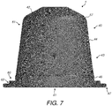
- Figures 7 to 12 illustrate a second embodiment of capsule 1.
- Features corresponding to those of the first embodiment are denoted by corresponding reference signs.
- Features of the first embodiment and this embodiment may be interchanged and combined as desired.
- only differences between the embodiments will be described in detail. In other respects the reader is directed to the description of the prior embodiment.
- the cup-shaped body 40 differs from that of the first embodiment in the configuration and geometry of the annular trough 60.
- the annular trough 60 is dimensioned to receive, partially or wholly, the leading edge 23 of the enclosing member 2 on movement of the enclosing member 2 into the closed position.
- the inner wall 65 of the annular trough 60 is substantially perpendicular to the floor 64.
- the outer wall 66 is angled relative to the floor 64, such that an internal angle ⁇ at a junction between the floor 64 and the outer wall 66 is from 90° to 120°, preferably 105°.
- the ridge zone 63 is again located radially outwards of the annular trough 60 and comprises an annular projection which extends back in the general direction of the base 42 such that an apex 67 of the ridge zone 63 is raised above the level of the floor 64 of the annular trough 60.
- the apex 67 may be raised above the floor 64 by a distance from 0.75 to 2.5 mm. As illustrated in this embodiment, the distance is 2.2 mm.
- the ridge zone 63 may be formed to have an inner wall provided by the angled outer wall 66 of the annular trough 60 and an outer wall 68 formed by at least a portion of the second side wall section 62.
- the second side wall section 62 may comprise between the outer wall 68 and the rolled-over portion 48 of the rim 47 an additional annular ridge 70 which may provide additional stiffness to the outer portion of the flange.
- the height of the additional annular ridge 70 may be 0.7 to 0.8 mm.
- the side wall 43 including the annular trough 60 and the ridge zone 63 may be formed integrally. Further, the cup-shaped body 40 including the side wall 43 and the base 42 may be formed integrally.
- the annular trough 60 may have an internal width of from 1.3 to 2.0 mm. As illustrated, the annular trough 60 has an internal width of approximately 1.5 mm to 1.8 mm.
- the lid 41 is sealed to the annular trough 60.
- the lid 41 is sealed to an inner surface of the floor 64 of the annular trough 60.
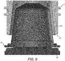
- the floor 64 of the annular trough 60 is substantially level with a distal end of the side wall 43 prior to insertion. As illustrated the offset from the distal end of the side wall 43 and the lid is only 0.2 mm.
- Figure 9 illustrates that the leading edge 23 of the enclosing member 2 may comprise an inner rim 23a and an outer rim 23b which are concentric and spaced apart from one another to define a recess 23c there between, which may be generally annular (although may have interruptions around its circumference).
- the side wall 43 of the capsule 1 is contacted by the enclosing member 2 to deform the side wall 43.
- the inner rim 23a of the leading edge 23 is received in the annular trough 60 and bears on the outer wall 66 while at the same time (or shortly thereafter) the apex 67 of the ridge zone 63 is received in the recess 23c.
- the ridge zone 63 (and floor 64) is driven downwards by the action of the enclosing member 2 on the outer wall 66 and/or apex 67 causing the outer wall 66 of the annular trough 60 and the outer wall 68 of the ridge zone 63 to buckle and deform/crumple.
- the material of the outer wall 66 of the annular trough 60 may be plastically drawn over the leading edge 23 to conform the outer wall 66 of the annular trough 60 to the grooves or indentations to provide an effective seal.
- the downward movement of the ridge zone 63 also nips the floor 64 (and the lid 41 sealed to the floor 64) against the capsule holder 20 as shown in Figure 12 .
- the geometry of the outer wall 68 of the ridge zone 63, with the additional annular ridge 70 helps to stiffen the distal end of the side wall 43 and prevent the rim 47 being deflected down into contact with the capsule holder 20.
- Piercing and brewing of a beverage from the capsule 1 may be as described above in the first embodiment.
- Figures 13 to 18 illustrate a third embodiment of capsule 1.
- Features corresponding to those of the first and/or second embodiment are denoted by corresponding reference signs.
- Features of the first and/or second embodiment and this embodiment may be interchanged and combined as desired.
- only differences between the embodiments will be described in detail. In other respects the reader is directed to the description of the prior embodiments.
- the cup-shaped body 40 differs from that of the first and second embodiments in the configuration and geometry of the annular trough 60.
- the annular trough 60 is dimensioned to receive, partially or wholly, the leading edge 23 of the enclosing member 2 on movement of the enclosing member 2 into the closed position.
- the inner wall 65 of the annular trough 60 is substantially perpendicular to the floor 64 and the outer wall 66 is angled relative to the floor 64, such that an internal angle ⁇ at a junction between the floor 64 and the outer wall 66 is from 90° to 120°, preferably 105°.
- the ridge zone 63 is again located radially outwards of the annular trough 60 and comprises an annular projection which extends back in the general direction of the base 42 such that an apex 67 of the ridge zone 63 is raised above the level of the floor 64 of the annular trough 60.
- the apex 67 is somewhat more rounded than in the second embodiment.
- the apex 67 may be raised above the floor 64 by a distance from 0.75 to 2.5 mm. As illustrated in this embodiment, the distance is 2.2 mm.
- the ridge zone 63 may be formed to have an inner wall provided by the angled outer wall 66 of the annular trough 60 and an outer wall 68 formed by at least a portion of the second side wall section 62.
- the outer wall 68 comprises three distinct sections - an upper section 73 which, prior to insertion, is perpendicular to the floor 64, a mid-section 71 that is angled at an angle ⁇ of from 20 to 80°, preferably 60°, to the vertical and a lower section 72 that includes a horizontal portion - parallel to the floor 64 - before merging into the rolled-over portion 48 of the rim 47.
- the side wall 43 including the annular trough 60 and the ridge zone 63 may be formed integrally. Further, the cup-shaped body 40 including the side wall 43 and the base 42 may be formed integrally.
- the annular trough 60 may have an internal width of from 1.3 to 2.0 mm. As illustrated, the annular trough 60 has an internal width of approximately 1.5 mm to 1.8 mm.
- the lid 41 is sealed to the annular trough 60.
- the lid 41 is sealed to an inner surface of the floor 64 of the annular trough 60.
- the floor 64 of the annular trough 60 is substantially level with a distal end of the side wall 43 prior to insertion. As illustrated the offset from the distal end of the side wall 43 and the lid is only 0.2 mm.
- the side wall 43 of the capsule 1 is contacted by the enclosing member 2 to deform the side wall 43.
- the inner rim 23a of the leading edge 23 is received in the annular trough 60 and bears on the outer wall 66 while at the same time (or shortly thereafter) the apex 67 of the ridge zone 63 is received in the recess 23c.
- the ridge zone 63 (and floor 64) is driven downwards by the action of the enclosing member 2 on the outer wall 66 and/or apex 67 causing the outer wall 66 of the annular trough 60 and the outer wall 68 of the ridge zone 63 to buckle and deform/crumple.
- the material of the outer wall 66 of the annular trough 60 may be plastically drawn over the leading edge 23 to conform the outer wall 66 of the annular trough 60 to the grooves or indentations to provide an effective seal.
- the downward movement of the ridge zone 63 also nips the floor 64 (and the lid 41 sealed to the floor 64) against the capsule holder 20 as shown in Figure 12 .
- the geometry of the outer wall 68 of the ridge zone 63, with the upper section 73, mid-section 71 and lower section 72 helps to stiffen the distal end of the side wall 43 and prevent the rim 47 being deflected down into contact with the capsule holder 20.
- Piercing and brewing of a beverage from the capsule 1 may be as described above in the first embodiment.
- the capsule 1 of any of the above embodiments may comprise a side wall 43 formed from a laminate material as discussed above having a polymer layer.
- Closure of the enclosing member 2 may compress at least the polymer layer of the laminate material when forming any of the sealing interfaces mentioned above.
- the compression of the polymer layer may aid the conforming of the side wall 43 to the shape of the leading edge 23.
- the polymer layer may aid filling of any gaps arising due to the presence of grooves in the leading edge 23.
- the polymer layer is directed outwardly to be directly contacted by the leading edge 23.
- the cup-shaped body 40 may comprise a unitary piece of laminate material.
- the laminate may comprise a ductile structural layer formed from a material such as aluminium or an aluminium alloy together with a resilient layer formed from a polymer.
- the laminate may comprise only a single layer of aluminium or aluminium alloy together with a single layer of polymer together with one or more optional lacquer layers, tie layers or adhesive layers applied to the aluminium or aluminium alloy.
- the polymer layer may, for example, comprise a material selected from the group of: polyvinyl chloride (PVC), polypropylene (PP), low density polyethylene (LDPE), medium density polyethylene (MDPE), high density polyethylene (HDPE), fluorinated ethylene propylene (FEP), polytetrafluoroethylene (PTFE), polyethylene terephthalate (PET), polyamide (PA), ethylene propylene diene monomer (EPDM), polychloroprene or isobutylene.
- PVC polyvinyl chloride
- PP polypropylene
- LDPE low density polyethylene
- MDPE medium density polyethylene
- HDPE high density polyethylene
- FEP fluorinated ethylene propylene
- PTFE polytetrafluoroethylene
- PET polyethylene terephthalate
- PA ethylene propylene diene monomer
- EPDM ethylene propylene diene monomer
- the hot water passed through the receptacle 3 may act to slightly soften the material of the polymer layer. Such softening may lead to further deformation of the side wall 43 under the compressive loading of the enclosing member 2. This effect may help to reinforce the fluid seal between the enclosing member 2 and the capsule 1 by tending to seal up any gaps having hot water leaking there through.
- the deformation of the side wall 43 will also typically cause a reduction in the longitudinal height of the capsule 1 relative to its height prior to insertion.
Priority Applications (1)
| Application Number | Priority Date | Filing Date | Title |
|---|---|---|---|
| EP22206144.2A EP4190211A1 (de) | 2013-05-17 | 2014-05-16 | Getränkezubereitungssystem, kapsel und verfahren zur herstellung eines getränks |
Applications Claiming Priority (5)
| Application Number | Priority Date | Filing Date | Title |
|---|---|---|---|
| GBGB1308929.7A GB201308929D0 (en) | 2013-05-17 | 2013-05-17 | A beverage preparation system, a capsule and a method for forming a beverage |
| GBGB1308925.5A GB201308925D0 (en) | 2013-05-17 | 2013-05-17 | A beverage preparation system, a capsule and a method for forming a beverage |
| PCT/IB2014/000858 WO2014184652A1 (en) | 2013-05-17 | 2014-05-16 | A beverage preparation system, a capsule and a method for forming a beverage |
| EP18169985.1A EP3375333B1 (de) | 2013-05-17 | 2014-05-16 | Getränkeherstellungssystem |
| EP14730192.3A EP2996521B1 (de) | 2013-05-17 | 2014-05-16 | Getränkeherstellungssystem, kapsel und verfahren zur herstellung eines getränks |
Related Parent Applications (3)
| Application Number | Title | Priority Date | Filing Date |
|---|---|---|---|
| EP18169985.1A Division EP3375333B1 (de) | 2013-05-17 | 2014-05-16 | Getränkeherstellungssystem |
| EP18169985.1A Division-Into EP3375333B1 (de) | 2013-05-17 | 2014-05-16 | Getränkeherstellungssystem |
| EP14730192.3A Division EP2996521B1 (de) | 2013-05-17 | 2014-05-16 | Getränkeherstellungssystem, kapsel und verfahren zur herstellung eines getränks |
Related Child Applications (1)
| Application Number | Title | Priority Date | Filing Date |
|---|---|---|---|
| EP22206144.2A Division EP4190211A1 (de) | 2013-05-17 | 2014-05-16 | Getränkezubereitungssystem, kapsel und verfahren zur herstellung eines getränks |
Publications (2)
| Publication Number | Publication Date |
|---|---|
| EP3656259A1 true EP3656259A1 (de) | 2020-05-27 |
| EP3656259B1 EP3656259B1 (de) | 2022-11-09 |
Family
ID=50942711
Family Applications (4)
| Application Number | Title | Priority Date | Filing Date |
|---|---|---|---|
| EP22206144.2A Pending EP4190211A1 (de) | 2013-05-17 | 2014-05-16 | Getränkezubereitungssystem, kapsel und verfahren zur herstellung eines getränks |
| EP18169985.1A Active EP3375333B1 (de) | 2013-05-17 | 2014-05-16 | Getränkeherstellungssystem |
| EP20151759.6A Active EP3656259B1 (de) | 2013-05-17 | 2014-05-16 | Kapsel und verfahren zur herstellung eines getränks |
| EP14730192.3A Active EP2996521B1 (de) | 2013-05-17 | 2014-05-16 | Getränkeherstellungssystem, kapsel und verfahren zur herstellung eines getränks |
Family Applications Before (2)
| Application Number | Title | Priority Date | Filing Date |
|---|---|---|---|
| EP22206144.2A Pending EP4190211A1 (de) | 2013-05-17 | 2014-05-16 | Getränkezubereitungssystem, kapsel und verfahren zur herstellung eines getränks |
| EP18169985.1A Active EP3375333B1 (de) | 2013-05-17 | 2014-05-16 | Getränkeherstellungssystem |
Family Applications After (1)
| Application Number | Title | Priority Date | Filing Date |
|---|---|---|---|
| EP14730192.3A Active EP2996521B1 (de) | 2013-05-17 | 2014-05-16 | Getränkeherstellungssystem, kapsel und verfahren zur herstellung eines getränks |
Country Status (17)
| Country | Link |
|---|---|
| US (2) | US10273076B2 (de) |
| EP (4) | EP4190211A1 (de) |
| JP (4) | JP2016524485A (de) |
| KR (2) | KR102149076B1 (de) |
| CN (2) | CN110239844B (de) |
| AU (2) | AU2014266921C1 (de) |
| BR (2) | BR112015028311B1 (de) |
| CA (1) | CA2901582C (de) |
| DE (2) | DE202014011368U1 (de) |
| DK (3) | DK3656259T3 (de) |
| ES (3) | ES2933099T3 (de) |
| HK (1) | HK1223804A1 (de) |
| NO (1) | NO2996521T3 (de) |
| PL (3) | PL3656259T3 (de) |
| PT (3) | PT3656259T (de) |
| RU (1) | RU2647791C2 (de) |
| WO (1) | WO2014184652A1 (de) |
Cited By (1)
| Publication number | Priority date | Publication date | Assignee | Title |
|---|---|---|---|---|
| EP3656259B1 (de) | 2013-05-17 | 2022-11-09 | Koninklijke Douwe Egberts B.V. | Kapsel und verfahren zur herstellung eines getränks |
Families Citing this family (61)
| Publication number | Priority date | Publication date | Assignee | Title |
|---|---|---|---|---|
| US10722066B2 (en) * | 2010-12-04 | 2020-07-28 | Adrian Rivera | Windowed single serving brewing material holder |
| US11832755B2 (en) * | 2007-07-13 | 2023-12-05 | Adrian Rivera | Brewing material container for a beverage brewer |
| EP3023361B1 (de) | 2010-07-22 | 2018-12-26 | K-fee System GmbH | Portionskapsel mit kennung |
| DE102012105282A1 (de) | 2012-06-18 | 2013-12-19 | K-Fee System Gmbh | Portionskapsel und Verfahren zur Herstellung eines Getränks mit einer Portionskapsel |
| DE102012223291A1 (de) | 2012-12-14 | 2014-06-18 | K-Fee System Gmbh | Portionskapsel und Verfahren zur Herstellung eines Getränks mit einer Portionskapsel |
| GB201308927D0 (en) | 2013-05-17 | 2013-07-03 | Kraft Foods R & D Inc | A beverage preparation system, a capsule and a method for forming a beverage |
| ITVR20130243A1 (it) | 2013-11-08 | 2015-05-09 | Caffita System Spa | Capsula e sistema per la produzione di bevande |
| ES2680630T3 (es) | 2014-01-03 | 2018-09-10 | Koninklijke Douwe Egberts B.V. | Envase de suministro intercambiable para una máquina dispensadora de bebidas, dosificador, unidad de bomba y método de fabricación |
| GB201420262D0 (en) | 2014-11-14 | 2014-12-31 | Kraft Foods R & D Inc | A method of forming a cup-shaped body for a beverage capsule |
| CA2977907C (en) | 2015-02-27 | 2019-10-22 | K-Fee System Gmbh | Single serve capsule comprising a filter element connected thereto by sealing |
| CN107848702B (zh) * | 2015-05-15 | 2020-08-04 | 皇家戴维艾格伯茨有限公司 | 胶囊、用于从这种胶囊制备饮用饮料的系统以及在饮料制备装置中使用这种胶囊的使用方法 |
| PT3134334T (pt) * | 2015-05-15 | 2019-06-14 | Douwe Egberts Bv | Cápsula, sistema para preparar uma bebida potável a partir de tal cápsula e utilização de tal cápsula num dispositivo de preparação de bebida |
| RU2710763C2 (ru) | 2015-05-15 | 2020-01-13 | Конинклейке Дауве Егбертс Б.В. | Капсула, система для приготовления пригодного для питья напитка из подобной капсулы и применение подобной капсулы в устройстве для приготовления напитков |
| EP3134331B1 (de) * | 2015-05-15 | 2018-07-11 | Koninklijke Douwe Egberts B.V. | Kapsel, system zur vorbereitung von getränken und verwendung dieser kapseln |
| KR102596448B1 (ko) | 2015-05-15 | 2023-10-30 | 코닌클리케 도우베 에그베르츠 비.브이. | 캡슐, 이러한 캡슐로부터 마실 수 있는 음료를 제조하기 위한 시스템 및 음료 제조 장치 내의 이러한 캡슐의 이용 |
| PL3134335T3 (pl) * | 2015-05-15 | 2018-12-31 | Koninklijke Douwe Egberts B.V. | Kapsułka, system do przygotowywania napoju z takiej kapsułki i zastosowanie takiej kapsułki w urządzeniu do przygotowywania napoju |
| CH711083B1 (de) * | 2015-05-15 | 2017-06-15 | Douwe Egberts Bv | Kapsel, System zur Zubereitung eines Getränks aus einer solchen Kapsel und Verwendung einer solchen Kapsel in einer Getränkezubereitungsvorrichtung. |
| CA2985975A1 (en) * | 2015-05-15 | 2016-11-24 | Koninklijke Douwe Egberts B.V. | A capsule, a system for preparing a potable beverage from such a capsule and use of such a capsule in a beverage preparation device |
| CN111674736B (zh) * | 2015-05-15 | 2022-06-17 | 皇家戴维艾格伯茨有限公司 | 胶囊以及用于由这种胶囊制备饮用饮料的系统 |
| CH711126A1 (de) * | 2015-05-27 | 2016-11-30 | Swiss Coffee Company Ag | Kapsel zur Verwendung in einer Extraktionsmaschine und Extraktionsverfahren unter Verwendung einer solchen Kapsel. |
| RU2698516C2 (ru) | 2015-06-10 | 2019-08-28 | К-Фее Зюстем Гмбх | Порционная капсула с трехслойным нетканым материалом |
| US10737876B2 (en) | 2015-07-13 | 2020-08-11 | K-Fee System Gmbh | Filter element having a cut-out |
| CN108025864A (zh) | 2015-09-18 | 2018-05-11 | K-Fee系统股份有限公司 | 用于定份胶囊的适配器 |
| EP3368447B1 (de) | 2015-10-27 | 2020-04-22 | Koninklijke Douwe Egberts B.V. | Kapsel, system und verfahren zu zubereitung von getränken |
| ES2580155B1 (es) * | 2016-01-05 | 2017-08-01 | Cup Out Of The Box, S.L. | Conjunto, cápsula y procedimiento para preparar infusiones |
| NL2016780B1 (en) * | 2016-05-13 | 2017-11-16 | Douwe Egberts Bv | A capsule, a system for preparing a potable beverage from such a capsule and use of such a capsule in a beverage preparation device |
| NL2016779B1 (en) | 2016-05-13 | 2017-11-16 | Douwe Egberts Bv | A capsule and a system for preparing a potable beverage from such a capsule |
| EP3490908B1 (de) * | 2016-07-26 | 2020-10-28 | Société des Produits Nestlé S.A. | Kapsel und getränkeherstellungssystem |
| WO2018024587A1 (en) | 2016-08-03 | 2018-02-08 | Nestec S.A. | Capsule for the preparation of a beverage containing pellets |
| IT201600082459A1 (it) * | 2016-08-04 | 2018-02-04 | Bisio Progetti Spa | Capsula per la preparazione di bevande ad infusione e solubili |
| AT519177B1 (de) * | 2016-10-06 | 2019-04-15 | Trotec Laser Gmbh | Verfahren zum Gravieren, Markieren und/oder Beschriften eines Werkstückes mit |
| DE102016012044A1 (de) * | 2016-10-07 | 2018-04-12 | Xpressivo Ag | Kapseldichtung mit doppelter Zentrierfunktion |
| WO2018067009A1 (en) | 2016-10-07 | 2018-04-12 | Koninklijke Douwe Egberts B.V. (Utrecht) | A capsule, a system for preparing a potable beverage from such a capsule and use of such a capsule in a beverage preparation device |
| NL2019254B9 (en) | 2016-10-07 | 2018-09-10 | Douwe Egberts Bv | A capsule, a system for preparing a potable beverage from such a capsule and use of such a capsule in a beverage preparation device |
| KR20180043876A (ko) * | 2016-10-20 | 2018-05-02 | 주식회사 자로 | 검은콩 캡슐 |
| CA3041722A1 (en) | 2016-11-09 | 2018-05-17 | Pepsico, Inc. | Carbonated beverage makers, methods, and systems |
| EP3372528A1 (de) * | 2017-03-10 | 2018-09-12 | ITC Packaging, S.L.U. | In-mold-markierter behälter zur herstellung von getränken |
| RU2766034C2 (ru) | 2017-04-04 | 2022-02-07 | Сосьете Де Продюи Нестле С.А. | Капсула для приготовления напитка с уплотнительным элементом, выполненным как единое целое |
| NL2019253B1 (en) | 2017-07-14 | 2019-01-28 | Douwe Egberts Bv | Assembly of a capsule and a brew chamber, brew chamber, beverage preparation machine, capsule and use of a capsule. |
| RU2665595C1 (ru) * | 2017-08-23 | 2018-08-31 | Общество с ограниченной ответственностью "ОРИМИ" (ООО "ОРИМИ") | Капсула для приготовления напитка |
| PT3710379T (pt) * | 2017-11-13 | 2021-09-09 | David Rubinstein | Cápsula para preparação de uma bebida |
| KR102185677B1 (ko) * | 2017-11-21 | 2020-12-02 | 엘지전자 주식회사 | 음료재료캡슐 및 이를 포함하는 음료 제조기 |
| EP3733556A4 (de) * | 2017-12-28 | 2021-09-15 | AMV Caps, S.L. | Teekapsel |
| IT201800002310A1 (it) * | 2018-02-01 | 2019-08-01 | Sarong Spa | Capsula per bevande |
| IT201800003290A1 (it) | 2018-03-05 | 2019-09-05 | Marco Agostini | Impianto di essiccazione delle pelli |
| CA3094348C (en) * | 2018-04-23 | 2021-06-29 | 2266170 Ontario Inc. | Capsules and other containers with optimized recycling attributes and methods for making same |
| JP1643129S (de) * | 2018-06-28 | 2019-10-07 | ||
| JP1643001S (de) * | 2018-06-28 | 2019-10-07 | ||
| TW202023919A (zh) | 2018-09-14 | 2020-07-01 | 瑞士商雀巢製品股份有限公司 | 用於飲料製備之具有一體地形成的密封部件之膠囊 |
| WO2020074550A1 (en) | 2018-10-10 | 2020-04-16 | Société des Produits Nestlé S.A. | Capsule for beverage preparation with integrally formed sealing member |
| EP3863945A1 (de) | 2018-10-10 | 2021-08-18 | Société des Produits Nestlé S.A. | Kapsel zur herstellung von getränken mit angeformtem dichtungselement |
| NL2022269B1 (en) * | 2018-12-20 | 2020-07-15 | Douwe Egberts Bv | System for preparing a beverage from a capsule using a fluid supplied under pressure into the capsule and a capsule for use in such a system |
| NL2022265B1 (en) * | 2018-12-20 | 2020-07-15 | Douwe Egberts Bv | System for preparing a beverage from a capsule using a fluid supplied under pressure into the capsule and a capsule for use in such a system |
| CA3129448A1 (en) * | 2019-02-13 | 2020-08-20 | Gcs German Capsule Solution Gmbh | Single-serve capsule for preparing a beverage in a beverage preparation machine, and system for preparing a beverage from said single-serve capsule |
| EP3702298A1 (de) | 2019-03-01 | 2020-09-02 | Delica AG | Kapsel und system für die zubereitung eines flüssigen lebensmittels |
| NL2022931B1 (nl) | 2019-04-11 | 2020-10-20 | Stas I P B V | Bereidingssysteem voor het extraheren van in een capsule aanwezig product |
| IT201900011385A1 (it) * | 2019-07-10 | 2021-01-10 | Sandro Mizzon | Capsula in alluminio contenente una sostanza in polvere per la preparazione di bevande |
| BR112022002842A2 (pt) * | 2019-10-02 | 2022-07-19 | Novelis Inc | Produto de alumínio laminado plano com conteúdo reciclado alto para soluções de embalagens de calibre leve e métodos relacionados |
| TW202136130A (zh) * | 2019-12-17 | 2021-10-01 | 瑞士商雀巢製品股份有限公司 | 由鋁合金製成之用於製備飲料之膠囊 |
| US11805934B1 (en) * | 2020-10-21 | 2023-11-07 | Adrian Rivera | Brewing material lid and container for a beverage brewer |
| RU204761U1 (ru) * | 2021-03-22 | 2021-06-09 | Виталий Павлович Панкратов | Держатель с капсулой для приготовления напитков |
Citations (9)
| Publication number | Priority date | Publication date | Assignee | Title |
|---|---|---|---|---|
| US2968560A (en) | 1959-02-06 | 1961-01-17 | Sealpak Corp | Infusion package for producing a coffee beverage |
| US5948455A (en) | 1996-05-10 | 1999-09-07 | Nestec S.A. | Cartridge having sheared thinned areas for promoting opening for beverage extraction |
| EP1700548A1 (de) | 2004-10-25 | 2006-09-13 | Nestec S.A. | Kapsel mit Dichtungsmitteln |
| DE102008014758A1 (de) * | 2008-03-18 | 2009-10-08 | Inde Plastik Betriebsgesellschaft Mbh | Geschlossene Portionspackung mit Dichtung |
| WO2010034663A1 (en) | 2008-09-23 | 2010-04-01 | Nestec S.A. | Process for producing bicoloured aluminium containers |
| WO2010066705A1 (en) | 2008-12-09 | 2010-06-17 | Nestec S.A. | Capsule for preparing a beverage by centrifugation in a beverage preparation device and device adapted therefore |
| WO2012118367A1 (en) * | 2011-03-03 | 2012-09-07 | Biserkon Holdings Ltd. | Capsule, device and method for preparing a beverage by extraction |
| WO2012120459A1 (fr) * | 2011-03-07 | 2012-09-13 | Ethical Coffee Company Sa | Capsule pour la preparation d'une boisson et porte-capsule adapte |
| WO2013136209A1 (en) * | 2012-03-14 | 2013-09-19 | Caffita System S.P.A. | System for making beverages |
Family Cites Families (103)
| Publication number | Priority date | Publication date | Assignee | Title |
|---|---|---|---|---|
| US3233813A (en) | 1963-07-31 | 1966-02-08 | Reynolds Metals Co | Pie plate receptacle with stepped flange |
| CA941663A (en) | 1969-11-26 | 1974-02-12 | E. I. Du Pont De Nemours And Company | Co-irradiation method and system for simultaneously imaging and fixing a photosensitive composition |
| FR2082002A5 (de) | 1969-12-09 | 1971-12-10 | Ethylene Plastique Sa | |
| US3695084A (en) | 1970-11-24 | 1972-10-03 | Reynolds Metals Co | Nestable container and apparatus for and method of making same |
| US3987720A (en) | 1975-09-15 | 1976-10-26 | The Raymond Lee Organization, Inc. | No drip pie plate |
| CH605293A5 (de) | 1976-12-17 | 1978-09-29 | Nestle Sa | |
| IT1194662B (it) | 1980-06-11 | 1988-09-22 | Giuseppe Stefano Piana | Macchina per la preparazione di caffe' espresso,cappuccino,te',brodo o di altri infusi,azionata automaticamente,mediante un filtro a perdere,contenente una o piu' dosi di prodotti,introdotto a mo' di gettone |
| GB2104049B (en) | 1981-02-27 | 1985-06-19 | Nestle Sa | Sealing process for filled containers |
| US4762514A (en) | 1985-11-01 | 1988-08-09 | Fujimori Kogyo Co., Ltd. | Method of making beverage packaging bag |
| US5178293A (en) | 1986-04-08 | 1993-01-12 | Idemitsu Petrochemical Co., Ltd. | Easily-openable packaging container |
| DE3641127A1 (de) | 1986-12-02 | 1988-06-16 | Lentia Gmbh | Verfahren zur herstellung von woelbteilen aus metall-thermoplast-verbunden |
| US4865217A (en) | 1987-08-31 | 1989-09-12 | Sumitomo Bakelite Company, Limited | Easily openable sealed container |
| CA2007748C (en) | 1989-08-31 | 1996-01-02 | Eiji Tamura | Food packaging container |
| FR2660220B1 (fr) | 1990-04-03 | 1995-02-24 | Lorraine Laminage | Procede et dispositif de formage d'une partie en relief sur un flan de tole et produit obtenu selon ce procede. |
| EP0468080B1 (de) | 1990-07-27 | 1994-12-28 | Societe Des Produits Nestle S.A. | Verfahren zur Extraktion von offenen Kaffeekapseln, Kaffeekapsel und Extraktionsvorrichtung zur Durchführung dieses Verfahrens |
| EP0468079B1 (de) | 1990-07-27 | 1996-09-18 | Societe Des Produits Nestle S.A. | Geschlossene Patrone zur Zubereitung eines Getränkes sowie Verfahren und Einrichtung zur Herstellung derselben |
| DE69002945T2 (de) | 1990-07-27 | 1994-01-20 | Nestle Sa | Verfahren zum Aufbrühen von geschlossenen Portionspackungen und Vorrichtung zur Durchführung dieses Verfahrens. |
| US5897899A (en) | 1991-05-08 | 1999-04-27 | Nestec S.A. | Cartridges containing substances for beverage preparation |
| AU1505192A (en) | 1991-05-10 | 1992-11-12 | Societe Des Produits Nestle S.A. | Sealed cartridge for the prepartion of a beverage |
| DK0521186T3 (da) | 1991-07-05 | 1995-04-18 | Nestle Sa | Blød emballage og fremgangsmåde til dens fremstilling |
| ZA924490B (en) | 1991-07-05 | 1993-03-31 | Nestle Sa | A flexible package with a stiffening element and a process for its production |
| DK0521510T3 (da) | 1991-07-05 | 1997-05-12 | Nestle Sa | Stiv kaffepatron og fremgangsmåde til fremstilling heraf |
| ATE112227T1 (de) | 1992-01-28 | 1994-10-15 | Nestle Sa | Geschlossene kapsel zur zubereitung eines getränkes. |
| ZA946726B (en) | 1993-09-10 | 1995-04-21 | Plastipak Packaging Inc | Polyethylene terephthalate multi-layer preform used for plastic blow molding and method for making the preform. |
| IT1285563B1 (it) | 1996-02-13 | 1998-06-18 | Pelliconi & C Spa | Coperchio, in particolare per contenitori di prodotti alimentari e procedimento per la sua realizzazione |
| ZA985765B (en) | 1997-07-02 | 1999-08-04 | Merck & Co Inc | Polymorphic form of a tachykinin receptor antagonist. |
| DK1190959T3 (da) | 2000-09-26 | 2004-06-28 | Nestle Sa | Lukket indsats, der er beregnet til fremstilling af en drik ved udtrækning under tryk |
| EP1203554A1 (de) | 2000-11-03 | 2002-05-08 | Societe Des Produits Nestle S.A. | Extraktionsvorrichtung für ein Nahrungsmittel das sich in einer Wiederladekartusche befindet |
| US6371335B1 (en) | 2000-12-07 | 2002-04-16 | Sealright Co., Inc. | Folded end construction for food sauce dispensing cartridges |
| ATE325756T1 (de) | 2002-03-14 | 2006-06-15 | Robert Hale | Kartusche für getränke, verfahren zu ihrer herstellung und filter dafür |
| ITTO20020481A1 (it) | 2002-06-07 | 2003-12-09 | Sgl Italia Srl | Metodo e dispositivo di foratura di una capsula sigillata in una macchina da caffe'. |
| GB2407758B (en) | 2003-01-24 | 2006-07-12 | Kraft Foods R & D Inc | Cartridge and method for the preparation of beverages |
| GB2409965B (en) * | 2003-01-24 | 2005-09-21 | Kraft Foods R & D Inc | A system and method for the preparation of beverages |
| AU2004288825B2 (en) | 2003-11-11 | 2009-01-08 | Graphic Packaging International, Inc. | Nestable container with uniform stacking features |
| ITCO20030012U1 (it) | 2003-12-29 | 2005-06-30 | Ilenaig Sas Di Giannelli Giuseppe | Capsula condensati bevande |
| US7556191B2 (en) | 2004-05-18 | 2009-07-07 | Evergreen Packaging, Inc. | Rupturable opening for sealed container |
| ATE449739T1 (de) | 2004-10-25 | 2009-12-15 | Nestec Sa | Kapsel mit elastisch federndem dichtungselement |
| DK1767467T3 (da) | 2005-09-21 | 2009-08-10 | Illycaffe Spa | Indsats indeholdende et stof til ekstrahering af en drik |
| ATE398955T1 (de) | 2006-03-31 | 2008-07-15 | Nestec Sa | Kapsel mit durch flüssigkeit gepresster aussendichtung |
| ES2326909T3 (es) | 2006-04-24 | 2009-10-21 | Nestec S.A. | Capsula para la preparacion de una bebida con un elemento de cierre hermetico unido a la misma y procedimiento de fabricacion de la misma. |
| US8176714B2 (en) | 2006-04-24 | 2012-05-15 | Nestec S.A. | Capsule for preparing a beverage with a sealing member for water tightness attached thereto and method of producing the same |
| JP5033179B2 (ja) * | 2006-05-29 | 2012-09-26 | ネステク ソシエテ アノニム | 変形可能なシール要素を有するコーヒーカプセル |
| US7947316B2 (en) | 2006-08-04 | 2011-05-24 | The Coca-Cola Company | Pod for dispersible materials |
| NL2000400C2 (nl) | 2006-12-22 | 2008-06-24 | Friesland Brands Bv | Cup voor concentraat en werkwijze voor bereiding van een vloeibaar product. |
| PT1944248T (pt) | 2007-01-15 | 2018-03-14 | Swiss Caffe Asia Ltd | Cápsula, meio de perfuração do fundo de uma cápsula e dispositivo para a preparação de uma bebida |
| US7910145B2 (en) | 2007-05-31 | 2011-03-22 | Marco Reati | Precharged ground coffee capsule, method for its production and apparatus for implementing said method |
| BRPI0812195B1 (pt) | 2007-06-05 | 2018-11-21 | Nestec Sa | cápsula de uso único para preparação de um líquido alimentício por centrifugação |
| DE602008006068D1 (de) * | 2007-06-05 | 2011-05-19 | Nestec Sa | Verfahren zur herstellung eines getränks oder flüssigen nahrungsmittels |
| PL2316310T3 (pl) | 2007-06-05 | 2012-10-31 | Nestec Sa | System i sposób do wytwarzania płynu spożywczego z substancji spożywczej zawartej w zbiorniku przez odwirowywanie |
| WO2008155749A1 (en) | 2007-06-18 | 2008-12-24 | Pt. Alcan Packaging Flexipack | Laminate packaging opening device |
| ATE508074T1 (de) | 2008-03-12 | 2011-05-15 | Nestec Sa | Kapsel mit flussregulierung und filterelement |
| US9572450B2 (en) | 2008-03-20 | 2017-02-21 | Nestec S.A. | Beverage production device for producing a beverage from a single-use capsule |
| ATE529248T1 (de) | 2008-07-15 | 2011-11-15 | Nestec Sa | Verfahren zur aufbringung eines flüssiggummisiegels auf eine kapsel |
| JP4399022B1 (ja) | 2008-10-21 | 2010-01-13 | 泉化成工業株式会社 | 延伸合成樹脂シートの成形方法 |
| US8962048B2 (en) | 2008-12-03 | 2015-02-24 | Nestec S.A. | Capsule for the preparation of a beverage by centrifugation |
| CN102272017B (zh) | 2009-01-05 | 2014-03-26 | 雀巢产品技术援助有限公司 | 具有流动控制和过滤部件的胶囊 |
| EP2210827B1 (de) | 2009-01-22 | 2012-09-26 | Nestec S.A. | Kapsel mit abnehmbaren Einspritzmitteln |
| WO2010084475A2 (fr) | 2009-01-23 | 2010-07-29 | Ethical Coffee Company Sa | Capsule pour la preparation d'une boisson |
| EP2364930B1 (de) | 2009-03-19 | 2018-12-05 | Nestec S.A. | Kapsel zur Zubereitung von Kaffee in einer Vorrichtung mit einem Kartuschenhalter mit Aussparung und eingelassenen Elementen |
| HUE026245T2 (en) | 2009-06-17 | 2016-06-28 | Douwe Egberts Bv | Capsules, systems and procedures for preparing a predetermined amount of beverage suitable for consumption |
| PT2456689E (pt) | 2009-07-24 | 2013-07-25 | Ethical Coffee Company Sa | Dispositivo para a preparação de uma bebida extraída a partir de uma capsula |
| PT2284101E (pt) | 2009-08-05 | 2011-11-30 | Nestec Sa | Cápsula com elemento de vedação em relevo |
| PT2284100E (pt) | 2009-08-05 | 2011-08-25 | Nestec Sa | Cápsula com meios de vedação dedicados |
| HUE025499T2 (en) | 2009-08-19 | 2016-04-28 | Nestec Sa | Coffee brewing capsule having a puncture-promoting structure for water injection |
| WO2011061126A2 (en) | 2009-11-19 | 2011-05-26 | Nestec S.A. | Capsule and method for preparing a beverage such as coffee from said capsule |
| EP2335529B1 (de) * | 2009-12-18 | 2012-08-08 | Delica AG | Vorrichtung zum Zubereiten eines Getränks und Kapsel |
| ITGE20100009A1 (it) | 2010-01-26 | 2010-04-27 | Marco Reati | Carica preconfezionata di polvere di caffe'. |
| DK2528485T3 (en) | 2010-01-29 | 2015-08-24 | Nestec Sa | CAPSULE AND SYSTEM FOR PRODUCING A DRINK FOR SPIN IN A beverage preparation device |
| ES2395510T5 (es) | 2010-04-07 | 2020-06-12 | Nestle Sa | Sistema de extracción para la producción de una bebida utilizando una cápsula |
| EP2394932B1 (de) | 2010-06-11 | 2013-06-05 | Alain Frydman | Kapsel mit Anbruchzone |
| EP2667758B1 (de) | 2011-01-24 | 2015-09-09 | Nestec S.A. | Kapsel und verfahren zur herstellung eines getränks durch zentrifugierung |
| ES2595245T3 (es) | 2011-01-28 | 2016-12-28 | Nestec S.A. | Sistema de producción de bebidas y cápsula con anillo de fuerza |
| IT1403541B1 (it) | 2011-01-31 | 2013-10-31 | Sarong Spa | Macchina erogatrice per bevande |
| IT1403855B1 (it) | 2011-02-17 | 2013-11-08 | E T I S R L | Capsula per il contenimento di un preparato per bevanda calda |
| CA2829071A1 (en) * | 2011-03-03 | 2012-10-26 | Biserkon Holdings Ltd. | Capsule, device and method for preparing a beverage by extraction |
| FR2972180B3 (fr) | 2011-03-04 | 2013-04-12 | Laurent Lombart | Kit ou ensemble pour la formation de capsules remplissables pour la preparation d'infusions |
| GB2489409B (en) | 2011-03-23 | 2013-05-15 | Kraft Foods R & D Inc | A capsule and a system for, and a method of, preparing a beverage |
| EP2562101A1 (de) | 2011-08-22 | 2013-02-27 | Nestec S.A. | Kapsel zur Verwendung in einer Getränkeherstellungsmaschine |
| NL2007417C2 (en) | 2011-09-14 | 2013-03-18 | Ahold Coffee Company B V | Capsule, and method of producing it. |
| ES2747814T3 (es) | 2011-09-28 | 2020-03-11 | Tuttoespresso Srl | Cápsula de bebida con un elemento de estanqueidad, sistema y procedimiento para preparar una bebida |
| ITMI20111847A1 (it) | 2011-10-10 | 2013-04-11 | Goglio Spa | Cartuccia per caffe' e prodotti solubili in genere |
| ES1075815Y (es) | 2011-10-25 | 2012-03-08 | Inventos Para Sist S Vending S L | Capsula monodosis para maquinas de cafe espresso |
| DE102011121647A1 (de) | 2011-12-19 | 2013-06-20 | riha WeserGold Getränke GmbH & Co. KG | Getränkebehälter mit Trinkhalm-Einstichöffnung |
| RU2623917C2 (ru) | 2011-12-21 | 2017-06-29 | Делика Аг | Капсула, система и способ для приготовления напитка |
| US20130224340A1 (en) | 2012-02-27 | 2013-08-29 | Hanan BenDavid | Optimal extraction rate coffee capsule with effective seal for diverse group heads |
| US8986763B2 (en) | 2012-02-27 | 2015-03-24 | Rialto Coffee Company Ltd. | Optimal extraction rate coffee capsule with effective seal for diverse group heads |
| ITBO20120103A1 (it) | 2012-03-05 | 2013-09-06 | Macchiavelli Srl | Capsula per prodotti da infusione |
| WO2013157924A1 (en) | 2012-04-17 | 2013-10-24 | Biserkon Holdings Ltd. | Capsule and device for preparing beverages and method for manufacturing a capsule |
| ES1077395Y (es) | 2012-06-26 | 2012-10-15 | Solubles S A Prod | Cápsula para preparar infusiones |
| DK2872421T3 (en) | 2012-07-16 | 2017-07-10 | Tuttoespresso Srl | ADJUSTABLE SUSPENSION SYSTEM |
| BR112015001036A2 (pt) | 2012-07-16 | 2017-06-27 | Tuttoespresso Srl | cápsula para preparar uma bebida em um dispositivo de infusão, tampa para uma cápsula para preparar bebidas, sistema para preparar bebidas e processo para preparar uma bebida a partir de uma cápsula |
| ES2651731T3 (es) | 2012-08-24 | 2018-01-29 | Nestec S.A. | Una cápsula para utilizar en una máquina de preparación de alimentos |
| CH707035A2 (de) | 2012-09-26 | 2014-03-31 | Alice Allison Sa | Portionenpackung für Espressomaschinen. |
| DE112013002899A5 (de) | 2012-10-29 | 2015-08-06 | Cstec Gmbh | Kapsel zur Aufnahme eines Brühguts wie Kaffee, Tee und desgleichen, sowie Verfahren zum Verschließen einer solchen Kapsel |
| EP2757055A1 (de) | 2013-01-17 | 2014-07-23 | Tuttoespresso S.r.l. | Kapsel und System zur Herstellung von Getränken |
| ITTO20130067A1 (it) | 2013-01-29 | 2014-07-30 | Bisio Progetti Spa | Capsula per la preparazione di bevande ad infusione. |
| ES1078818Y (es) | 2013-02-22 | 2013-06-10 | Solubles S A Prod | Cápsula para preparar infusiones |
| PT3656259T (pt) | 2013-05-17 | 2023-01-03 | Douwe Egberts Bv | Cápsula e método para a formação de uma bebida |
| GB201308927D0 (en) | 2013-05-17 | 2013-07-03 | Kraft Foods R & D Inc | A beverage preparation system, a capsule and a method for forming a beverage |
| GB201308929D0 (en) | 2013-05-17 | 2013-07-03 | Kraft Foods R & D Inc | A beverage preparation system, a capsule and a method for forming a beverage |
| WO2015101394A1 (en) | 2013-12-30 | 2015-07-09 | Landmax Ltd | Capsule for a beverage preparation with deformable sealing element |
| MX2016011191A (es) | 2014-02-28 | 2016-12-16 | Sacmi Coop Mecc Imola Societa' Coop | Taza para una capsula de cafe. |
| GB201420262D0 (en) | 2014-11-14 | 2014-12-31 | Kraft Foods R & D Inc | A method of forming a cup-shaped body for a beverage capsule |
-
2014
- 2014-05-16 PT PT201517596T patent/PT3656259T/pt unknown
- 2014-05-16 ES ES20151759T patent/ES2933099T3/es active Active
- 2014-05-16 PL PL20151759.6T patent/PL3656259T3/pl unknown
- 2014-05-16 US US14/786,142 patent/US10273076B2/en active Active
- 2014-05-16 EP EP22206144.2A patent/EP4190211A1/de active Pending
- 2014-05-16 PL PL18169985.1T patent/PL3375333T4/pl unknown
- 2014-05-16 BR BR112015028311-0A patent/BR112015028311B1/pt active IP Right Grant
- 2014-05-16 DK DK20151759.6T patent/DK3656259T3/da active
- 2014-05-16 ES ES18169985T patent/ES2806724T3/es active Active
- 2014-05-16 CN CN201910379467.4A patent/CN110239844B/zh active Active
- 2014-05-16 EP EP18169985.1A patent/EP3375333B1/de active Active
- 2014-05-16 RU RU2015147727A patent/RU2647791C2/ru active
- 2014-05-16 PT PT147301923T patent/PT2996521T/pt unknown
- 2014-05-16 PT PT181699851T patent/PT3375333T/pt unknown
- 2014-05-16 DK DK14730192.3T patent/DK2996521T3/en active
- 2014-05-16 CN CN201480026328.9A patent/CN105188488B/zh active Active
- 2014-05-16 WO PCT/IB2014/000858 patent/WO2014184652A1/en active Application Filing
- 2014-05-16 JP JP2016512435A patent/JP2016524485A/ja not_active Withdrawn
- 2014-05-16 NO NO14730192A patent/NO2996521T3/no unknown
- 2014-05-16 KR KR1020157031881A patent/KR102149076B1/ko active IP Right Grant
- 2014-05-16 BR BR122020005722-0A patent/BR122020005722B1/pt active IP Right Grant
- 2014-05-16 KR KR1020187030971A patent/KR102150783B1/ko active IP Right Grant
- 2014-05-16 ES ES14730192.3T patent/ES2668289T3/es active Active
- 2014-05-16 CA CA2901582A patent/CA2901582C/en active Active
- 2014-05-16 EP EP20151759.6A patent/EP3656259B1/de active Active
- 2014-05-16 DK DK18169985.1T patent/DK3375333T3/da active
- 2014-05-16 AU AU2014266921A patent/AU2014266921C1/en active Active
- 2014-05-16 DE DE202014011368.8U patent/DE202014011368U1/de not_active Withdrawn - After Issue
- 2014-05-16 DE DE202014011505.2U patent/DE202014011505U1/de active Active
- 2014-05-16 PL PL14730192.3T patent/PL2996521T4/pl unknown
- 2014-05-16 EP EP14730192.3A patent/EP2996521B1/de active Active
-
2016
- 2016-09-22 HK HK16111124.8A patent/HK1223804A1/zh unknown
-
2017
- 2017-03-02 AU AU2017201457A patent/AU2017201457A1/en not_active Abandoned
- 2017-07-31 JP JP2017148275A patent/JP6377223B2/ja active Active
-
2018
- 2018-07-24 JP JP2018138423A patent/JP6731018B2/ja active Active
-
2019
- 2019-04-01 US US16/372,187 patent/US20190225415A1/en active Pending
-
2020
- 2020-07-03 JP JP2020115415A patent/JP6900560B2/ja active Active
Patent Citations (9)
| Publication number | Priority date | Publication date | Assignee | Title |
|---|---|---|---|---|
| US2968560A (en) | 1959-02-06 | 1961-01-17 | Sealpak Corp | Infusion package for producing a coffee beverage |
| US5948455A (en) | 1996-05-10 | 1999-09-07 | Nestec S.A. | Cartridge having sheared thinned areas for promoting opening for beverage extraction |
| EP1700548A1 (de) | 2004-10-25 | 2006-09-13 | Nestec S.A. | Kapsel mit Dichtungsmitteln |
| DE102008014758A1 (de) * | 2008-03-18 | 2009-10-08 | Inde Plastik Betriebsgesellschaft Mbh | Geschlossene Portionspackung mit Dichtung |
| WO2010034663A1 (en) | 2008-09-23 | 2010-04-01 | Nestec S.A. | Process for producing bicoloured aluminium containers |
| WO2010066705A1 (en) | 2008-12-09 | 2010-06-17 | Nestec S.A. | Capsule for preparing a beverage by centrifugation in a beverage preparation device and device adapted therefore |
| WO2012118367A1 (en) * | 2011-03-03 | 2012-09-07 | Biserkon Holdings Ltd. | Capsule, device and method for preparing a beverage by extraction |
| WO2012120459A1 (fr) * | 2011-03-07 | 2012-09-13 | Ethical Coffee Company Sa | Capsule pour la preparation d'une boisson et porte-capsule adapte |
| WO2013136209A1 (en) * | 2012-03-14 | 2013-09-19 | Caffita System S.P.A. | System for making beverages |
Cited By (1)
| Publication number | Priority date | Publication date | Assignee | Title |
|---|---|---|---|---|
| EP3656259B1 (de) | 2013-05-17 | 2022-11-09 | Koninklijke Douwe Egberts B.V. | Kapsel und verfahren zur herstellung eines getränks |
Also Published As
Similar Documents
| Publication | Publication Date | Title |
|---|---|---|
| US20190225415A1 (en) | Beverage preparation system, a capsule and a method for forming a beverage | |
| EP2996966B1 (de) | Getränkeherstellungssystem, kapsel und verfahren zur herstellung eines getränks | |
| AU2014266922B2 (en) | A beverage preparation system, a capsule and a method for forming a beverage | |
| AU2020223699B2 (en) | A method of forming a cup-shaped body for a beverage capsule |
Legal Events
| Date | Code | Title | Description |
|---|---|---|---|
| PUAI | Public reference made under article 153(3) epc to a published international application that has entered the european phase |
Free format text: ORIGINAL CODE: 0009012 |
|
| STAA | Information on the status of an ep patent application or granted ep patent |
Free format text: STATUS: THE APPLICATION HAS BEEN PUBLISHED |
|
| AC | Divisional application: reference to earlier application |
Ref document number: 3375333 Country of ref document: EP Kind code of ref document: P Ref document number: 2996521 Country of ref document: EP Kind code of ref document: P |
|
| AK | Designated contracting states |
Kind code of ref document: A1 Designated state(s): AL AT BE BG CH CY CZ DE DK EE ES FI FR GB GR HR HU IE IS IT LI LT LU LV MC MK MT NL NO PL PT RO RS SE SI SK SM TR |
|
| STAA | Information on the status of an ep patent application or granted ep patent |
Free format text: STATUS: REQUEST FOR EXAMINATION WAS MADE |
|
| 17P | Request for examination filed |
Effective date: 20201127 |
|
| RBV | Designated contracting states (corrected) |
Designated state(s): AL AT BE BG CH CY CZ DE DK EE ES FI FR GB GR HR HU IE IS IT LI LT LU LV MC MK MT NL NO PL PT RO RS SE SI SK SM TR |
|
| TPAC | Observations filed by third parties |
Free format text: ORIGINAL CODE: EPIDOSNTIPA |
|
| STAA | Information on the status of an ep patent application or granted ep patent |
Free format text: STATUS: EXAMINATION IS IN PROGRESS |
|
| 17Q | First examination report despatched |
Effective date: 20210205 |
|
| TPAC | Observations filed by third parties |
Free format text: ORIGINAL CODE: EPIDOSNTIPA |
|
| GRAP | Despatch of communication of intention to grant a patent |
Free format text: ORIGINAL CODE: EPIDOSNIGR1 |
|
| STAA | Information on the status of an ep patent application or granted ep patent |
Free format text: STATUS: GRANT OF PATENT IS INTENDED |
|
| TPAC | Observations filed by third parties |
Free format text: ORIGINAL CODE: EPIDOSNTIPA |
|
| INTG | Intention to grant announced |
Effective date: 20220329 |
|
| TPAC | Observations filed by third parties |
Free format text: ORIGINAL CODE: EPIDOSNTIPA |
|
| TPAC | Observations filed by third parties |
Free format text: ORIGINAL CODE: EPIDOSNTIPA |
|
| GRAS | Grant fee paid |
Free format text: ORIGINAL CODE: EPIDOSNIGR3 |
|
| GRAA | (expected) grant |
Free format text: ORIGINAL CODE: 0009210 |
|
| STAA | Information on the status of an ep patent application or granted ep patent |
Free format text: STATUS: THE PATENT HAS BEEN GRANTED |
|
| AC | Divisional application: reference to earlier application |
Ref document number: 2996521 Country of ref document: EP Kind code of ref document: P Ref document number: 3375333 Country of ref document: EP Kind code of ref document: P |
|
| AK | Designated contracting states |
Kind code of ref document: B1 Designated state(s): AL AT BE BG CH CY CZ DE DK EE ES FI FR GB GR HR HU IE IS IT LI LT LU LV MC MK MT NL NO PL PT RO RS SE SI SK SM TR |
|
| REG | Reference to a national code |
Ref country code: GB Ref legal event code: FG4D |
|
| REG | Reference to a national code |
Ref country code: CH Ref legal event code: EP Ref country code: AT Ref legal event code: REF Ref document number: 1529794 Country of ref document: AT Kind code of ref document: T Effective date: 20221115 |
|
| REG | Reference to a national code |
Ref country code: DE Ref legal event code: R096 Ref document number: 602014085522 Country of ref document: DE |
|
| REG | Reference to a national code |
Ref country code: IE Ref legal event code: FG4D |
|
| REG | Reference to a national code |
Ref country code: DK Ref legal event code: T3 Effective date: 20221214 |
|
| REG | Reference to a national code |
Ref country code: NL Ref legal event code: FP |
|
| REG | Reference to a national code |
Ref country code: PT Ref legal event code: SC4A Ref document number: 3656259 Country of ref document: PT Date of ref document: 20230103 Kind code of ref document: T Free format text: AVAILABILITY OF NATIONAL TRANSLATION Effective date: 20221228 |
|
| REG | Reference to a national code |
Ref country code: NO Ref legal event code: T2 Effective date: 20221109 |
|
| REG | Reference to a national code |
Ref country code: SE Ref legal event code: TRGR |
|
| REG | Reference to a national code |
Ref country code: ES Ref legal event code: FG2A Ref document number: 2933099 Country of ref document: ES Kind code of ref document: T3 Effective date: 20230201 |
|
| REG | Reference to a national code |
Ref country code: LT Ref legal event code: MG9D |
|
| REG | Reference to a national code |
Ref country code: GR Ref legal event code: EP Ref document number: 20230400128 Country of ref document: GR Effective date: 20230307 |
|
| PG25 | Lapsed in a contracting state [announced via postgrant information from national office to epo] |
Ref country code: LT Free format text: LAPSE BECAUSE OF FAILURE TO SUBMIT A TRANSLATION OF THE DESCRIPTION OR TO PAY THE FEE WITHIN THE PRESCRIBED TIME-LIMIT Effective date: 20221109 Ref country code: FI Free format text: LAPSE BECAUSE OF FAILURE TO SUBMIT A TRANSLATION OF THE DESCRIPTION OR TO PAY THE FEE WITHIN THE PRESCRIBED TIME-LIMIT Effective date: 20221109 |
|
| PG25 | Lapsed in a contracting state [announced via postgrant information from national office to epo] |
Ref country code: RS Free format text: LAPSE BECAUSE OF FAILURE TO SUBMIT A TRANSLATION OF THE DESCRIPTION OR TO PAY THE FEE WITHIN THE PRESCRIBED TIME-LIMIT Effective date: 20221109 Ref country code: LV Free format text: LAPSE BECAUSE OF FAILURE TO SUBMIT A TRANSLATION OF THE DESCRIPTION OR TO PAY THE FEE WITHIN THE PRESCRIBED TIME-LIMIT Effective date: 20221109 Ref country code: IS Free format text: LAPSE BECAUSE OF FAILURE TO SUBMIT A TRANSLATION OF THE DESCRIPTION OR TO PAY THE FEE WITHIN THE PRESCRIBED TIME-LIMIT Effective date: 20230309 Ref country code: HR Free format text: LAPSE BECAUSE OF FAILURE TO SUBMIT A TRANSLATION OF THE DESCRIPTION OR TO PAY THE FEE WITHIN THE PRESCRIBED TIME-LIMIT Effective date: 20221109 |
|
| P01 | Opt-out of the competence of the unified patent court (upc) registered |
Effective date: 20230505 |
|
| PG25 | Lapsed in a contracting state [announced via postgrant information from national office to epo] |
Ref country code: SM Free format text: LAPSE BECAUSE OF FAILURE TO SUBMIT A TRANSLATION OF THE DESCRIPTION OR TO PAY THE FEE WITHIN THE PRESCRIBED TIME-LIMIT Effective date: 20221109 Ref country code: RO Free format text: LAPSE BECAUSE OF FAILURE TO SUBMIT A TRANSLATION OF THE DESCRIPTION OR TO PAY THE FEE WITHIN THE PRESCRIBED TIME-LIMIT Effective date: 20221109 Ref country code: EE Free format text: LAPSE BECAUSE OF FAILURE TO SUBMIT A TRANSLATION OF THE DESCRIPTION OR TO PAY THE FEE WITHIN THE PRESCRIBED TIME-LIMIT Effective date: 20221109 Ref country code: CZ Free format text: LAPSE BECAUSE OF FAILURE TO SUBMIT A TRANSLATION OF THE DESCRIPTION OR TO PAY THE FEE WITHIN THE PRESCRIBED TIME-LIMIT Effective date: 20221109 |
|
| PGFP | Annual fee paid to national office [announced via postgrant information from national office to epo] |
Ref country code: PT Payment date: 20230502 Year of fee payment: 10 Ref country code: NO Payment date: 20230530 Year of fee payment: 10 Ref country code: NL Payment date: 20230526 Year of fee payment: 10 Ref country code: IT Payment date: 20230519 Year of fee payment: 10 Ref country code: FR Payment date: 20230525 Year of fee payment: 10 Ref country code: ES Payment date: 20230601 Year of fee payment: 10 Ref country code: DK Payment date: 20230530 Year of fee payment: 10 Ref country code: DE Payment date: 20230530 Year of fee payment: 10 Ref country code: CH Payment date: 20230610 Year of fee payment: 10 |
|
| REG | Reference to a national code |
Ref country code: DE Ref legal event code: R026 Ref document number: 602014085522 Country of ref document: DE |
|
| PLAZ | Examination of admissibility of opposition: despatch of communication + time limit |
Free format text: ORIGINAL CODE: EPIDOSNOPE2 |
|
| PLBI | Opposition filed |
Free format text: ORIGINAL CODE: 0009260 |
|
| PLBA | Examination of admissibility of opposition: reply received |
Free format text: ORIGINAL CODE: EPIDOSNOPE4 |
|
| PLAB | Opposition data, opponent's data or that of the opponent's representative modified |
Free format text: ORIGINAL CODE: 0009299OPPO |
|
| PLAX | Notice of opposition and request to file observation + time limit sent |
Free format text: ORIGINAL CODE: EPIDOSNOBS2 |
|
| PG25 | Lapsed in a contracting state [announced via postgrant information from national office to epo] |
Ref country code: SK Free format text: LAPSE BECAUSE OF FAILURE TO SUBMIT A TRANSLATION OF THE DESCRIPTION OR TO PAY THE FEE WITHIN THE PRESCRIBED TIME-LIMIT Effective date: 20221109 Ref country code: AL Free format text: LAPSE BECAUSE OF FAILURE TO SUBMIT A TRANSLATION OF THE DESCRIPTION OR TO PAY THE FEE WITHIN THE PRESCRIBED TIME-LIMIT Effective date: 20221109 |
|
| PGFP | Annual fee paid to national office [announced via postgrant information from national office to epo] |
Ref country code: SE Payment date: 20230527 Year of fee payment: 10 Ref country code: PL Payment date: 20230508 Year of fee payment: 10 Ref country code: GR Payment date: 20230530 Year of fee payment: 10 Ref country code: AT Payment date: 20230504 Year of fee payment: 10 |
|
| 26 | Opposition filed |
Opponent name: MAUCHER JENKINS PATENTANWAELTE & RECHTSANWAELTE Effective date: 20230809 Opponent name: ALUSENSE NV Effective date: 20230809 Opponent name: DELICA AG Effective date: 20230808 |
|
| REG | Reference to a national code |
Ref country code: AT Ref legal event code: UEP Ref document number: 1529794 Country of ref document: AT Kind code of ref document: T Effective date: 20221109 |
|
| R26 | Opposition filed (corrected) |
Opponent name: ALUSENSE NV Effective date: 20230809 |
|
| PGFP | Annual fee paid to national office [announced via postgrant information from national office to epo] |
Ref country code: BE Payment date: 20230529 Year of fee payment: 10 |
|
| PGFP | Annual fee paid to national office [announced via postgrant information from national office to epo] |
Ref country code: GB Payment date: 20230529 Year of fee payment: 10 |
|
| PG25 | Lapsed in a contracting state [announced via postgrant information from national office to epo] |
Ref country code: SI Free format text: LAPSE BECAUSE OF FAILURE TO SUBMIT A TRANSLATION OF THE DESCRIPTION OR TO PAY THE FEE WITHIN THE PRESCRIBED TIME-LIMIT Effective date: 20221109 |
|
| PLBB | Reply of patent proprietor to notice(s) of opposition received |
Free format text: ORIGINAL CODE: EPIDOSNOBS3 |
|
| PG25 | Lapsed in a contracting state [announced via postgrant information from national office to epo] |
Ref country code: MC Free format text: LAPSE BECAUSE OF FAILURE TO SUBMIT A TRANSLATION OF THE DESCRIPTION OR TO PAY THE FEE WITHIN THE PRESCRIBED TIME-LIMIT Effective date: 20221109 |
|
| PG25 | Lapsed in a contracting state [announced via postgrant information from national office to epo] |
Ref country code: MC Free format text: LAPSE BECAUSE OF FAILURE TO SUBMIT A TRANSLATION OF THE DESCRIPTION OR TO PAY THE FEE WITHIN THE PRESCRIBED TIME-LIMIT Effective date: 20221109 Ref country code: LU Free format text: LAPSE BECAUSE OF NON-PAYMENT OF DUE FEES Effective date: 20230516 |
|
| REG | Reference to a national code |
Ref country code: IE Ref legal event code: MM4A |
|
| PG25 | Lapsed in a contracting state [announced via postgrant information from national office to epo] |
Ref country code: IE Free format text: LAPSE BECAUSE OF NON-PAYMENT OF DUE FEES Effective date: 20230516 |