EP3650918A1 - Optical device - Google Patents
Optical device Download PDFInfo
- Publication number
- EP3650918A1 EP3650918A1 EP18828995.3A EP18828995A EP3650918A1 EP 3650918 A1 EP3650918 A1 EP 3650918A1 EP 18828995 A EP18828995 A EP 18828995A EP 3650918 A1 EP3650918 A1 EP 3650918A1
- Authority
- EP
- European Patent Office
- Prior art keywords
- movable
- axis direction
- electrode
- unit
- pair
- Prior art date
- Legal status (The legal status is an assumption and is not a legal conclusion. Google has not performed a legal analysis and makes no representation as to the accuracy of the status listed.)
- Granted
Links
Images





Classifications
-
- H—ELECTRICITY
- H02—GENERATION; CONVERSION OR DISTRIBUTION OF ELECTRIC POWER
- H02N—ELECTRIC MACHINES NOT OTHERWISE PROVIDED FOR
- H02N1/00—Electrostatic generators or motors using a solid moving electrostatic charge carrier
- H02N1/002—Electrostatic motors
- H02N1/006—Electrostatic motors of the gap-closing type
- H02N1/008—Laterally driven motors, e.g. of the comb-drive type
-
- B—PERFORMING OPERATIONS; TRANSPORTING
- B81—MICROSTRUCTURAL TECHNOLOGY
- B81B—MICROSTRUCTURAL DEVICES OR SYSTEMS, e.g. MICROMECHANICAL DEVICES
- B81B3/00—Devices comprising flexible or deformable elements, e.g. comprising elastic tongues or membranes
-
- G—PHYSICS
- G01—MEASURING; TESTING
- G01J—MEASUREMENT OF INTENSITY, VELOCITY, SPECTRAL CONTENT, POLARISATION, PHASE OR PULSE CHARACTERISTICS OF INFRARED, VISIBLE OR ULTRAVIOLET LIGHT; COLORIMETRY; RADIATION PYROMETRY
- G01J3/00—Spectrometry; Spectrophotometry; Monochromators; Measuring colours
- G01J3/28—Investigating the spectrum
- G01J3/45—Interferometric spectrometry
-
- G—PHYSICS
- G02—OPTICS
- G02B—OPTICAL ELEMENTS, SYSTEMS OR APPARATUS
- G02B26/00—Optical devices or arrangements for the control of light using movable or deformable optical elements
- G02B26/06—Optical devices or arrangements for the control of light using movable or deformable optical elements for controlling the phase of light
-
- G—PHYSICS
- G02—OPTICS
- G02B—OPTICAL ELEMENTS, SYSTEMS OR APPARATUS
- G02B26/00—Optical devices or arrangements for the control of light using movable or deformable optical elements
- G02B26/08—Optical devices or arrangements for the control of light using movable or deformable optical elements for controlling the direction of light
- G02B26/0816—Optical devices or arrangements for the control of light using movable or deformable optical elements for controlling the direction of light by means of one or more reflecting elements
- G02B26/0833—Optical devices or arrangements for the control of light using movable or deformable optical elements for controlling the direction of light by means of one or more reflecting elements the reflecting element being a micromechanical device, e.g. a MEMS mirror, DMD
- G02B26/0841—Optical devices or arrangements for the control of light using movable or deformable optical elements for controlling the direction of light by means of one or more reflecting elements the reflecting element being a micromechanical device, e.g. a MEMS mirror, DMD the reflecting element being moved or deformed by electrostatic means
Definitions
- the present disclosure relates to an optical device that is constituted, for example, as a micro electro mechanical systems (MEMS) device.
- MEMS micro electro mechanical systems
- an optical device including a base, a movable unit including an optical function unit, and an elastic support unit that is connected between the base and the movable unit and supports the movable unit so that the movable unit is movable along a movement direction
- the optical device includes a movable comb electrode including a plurality of movable comb fingers, and a fixed comb electrode including a plurality of fixed comb fingers which are disposed alternately with the plurality of movable comb fingers in some cases.
- Patent Literature 1 US Unexamined Patent Publication No. 2008/0284078
- the movable comb electrode and the fixed comb electrode can be used as an electrode for driving, an electrode for monitoring, or an electrode for driving and monitoring.
- a voltage is applied to between the movable comb electrode and the fixed comb electrode to move the movable unit along a movement direction.
- electrostatic capacitance between the movable comb electrode and the fixed comb electrode is detected to understand a position of the movable unit that is moving along the movement direction.
- the movable comb electrode and the fixed comb electrode are used for either usage, it is preferable that the movable comb electrode moves integrally with the movable unit during movement of the movable unit along the movement direction, and an interval between the movable comb finger and the fixed comb finger adjacent to each other is constantly maintained.
- the movable comb electrode and the fixed comb electrode are merely provided, the movable comb electrode is distorted during movement of the movable unit along the movement direction, and thus there is a concern that reliability as a device may deteriorate.
- An object of an aspect of the present disclosure is to provide an optical device with high reliability.
- an optical device including: a base that includes a main surface; a movable unit that includes an optical function unit; an elastic support unit that is connected between the base and the movable unit, and supports the movable unit so that the movable unit is movable along a predetermined direction perpendicular to the main surface; a fixed comb electrode that is provided to the base and includes a plurality of fixed comb fingers; and a movable comb electrode that is provided to at least one of the movable unit and the elastic support unit, and includes a plurality of movable comb fingers which are disposed alternately with the plurality of fixed comb fingers.
- At least one of the movable unit and the elastic support unit includes an electrode support portion that supports the movable comb electrode, and the electrode support portion includes a rib portion that is formed so that the thickness of the electrode support portion in the predetermined direction is larger than the thickness of the movable comb fingers in the predetermined direction.
- the thickness of the electrode support portion in the predetermined direction is larger than the thickness of the movable comb fingers in the predetermined direction, and the movable comb electrode is supported by the electrode support portion. Accordingly, it is possible to suppress distortion of the electrode support portion that supports the movable comb electrode during movement of the movable unit along the predetermined direction. Accordingly, it is possible to move the movable comb electrode integrally with the movable unit, and it is possible to suppress fluctuation of an interval between the movable comb finger and the fixed comb finger adjacent to each other. As a result, it is possible to enhance reliability.
- the elastic support unit may include a lever, and the electrode support portion may extend from the lever. In this case, it is possible to suppress distortion of the movable comb electrode due to the electrode support portion that extends from the lever.
- the movable comb electrode may be located on a side opposite to the movable unit with respect to the center of the lever in an extending direction of the lever. In this case, even when the movable unit greatly moves along the predetermined direction, the movable comb fingers are less likely to deviate from a region between the fixed comb fingers adjacent to each other. Accordingly, in a case where the fixed comb electrode and the movable comb electrode can be used as an electrode for driving, it is possible to allow an electrostatic force to occur between the fixed comb electrode and the movable comb electrode over the entirety of a movable range of the movable unit.
- the fixed comb electrode and the movable comb electrode can be used as an electrode for monitoring, it is possible to detect a variation of electrostatic capacitance between the fixed comb electrode and the movable comb electrode over the entirety of the movable range of the movable unit.
- the movable comb electrode may be located on the movable unit side with respect to the center of the lever in an extending direction of the lever. In this case, it is possible to secure a distance from a connection position with respect to the base in the elastic support unit to the movable comb electrode. Accordingly, in a case where the fixed comb electrode and the movable comb electrode can be used as an electrode for driving, it is possible to use the electrostatic force that occurs between the fixed comb electrode and the movable comb electrode as a driving force of the movable unit with efficiency.
- the fixed comb electrode and the movable comb electrode can be used as an electrode for monitoring, a variation of the electrostatic capacitance between the fixed comb electrode and the movable comb electrode is great, and thus it is possible to easily and reliably detect a position of the movable unit.
- the lever may include a rib portion that is formed so that the thickness of the lever in the predetermined direction is larger than the thickness of the movable comb fingers in the predetermined direction. In this case, it is possible to more reliably suppress fluctuation of the interval between the movable comb finger and the fixed comb finger adjacent to each other, and it is possible to further improve the reliability.
- the elastic support unit may include a plurality of the electrode support portions which extend from the lever, and the plurality of electrode support portions may be disposed to be aligned along an extending direction of the lever.
- the plurality of electrode support portions are provided to a case where the fixed comb electrode and the movable comb electrode can be used as an electrode for driving, it is possible to secure a driving force.
- the fixed comb electrode and the movable comb electrode can be used as an electrode for monitoring, it is possible to easily and reliably detect a position of the movable unit.
- distortion of the electrode support portion that supports the movable comb electrode is suppressed by increasing the thickness of the electrode support portion instead of a width thereof, and thus it is possible to dispose the plurality of electrode support portions to be aligned along an extending direction of the lever.
- the thickness T1 of the electrode support portion in the predetermined direction and the thickness T2 of the movable comb finger in the predetermined direction may satisfy the following Expression (1), T 1 3 ⁇ W 1 / C 1 3 ⁇ N ⁇ T 2 3 ⁇ W 2 / C 2 3 in Expression (1) described above, W1: a width of the electrode support portion when viewed from the predetermined direction, C1: a length of the electrode support portion when viewed from the predetermined direction, N: the number of the movable comb fingers, W2: a width of the movable comb finger when viewed from the predetermined direction, and C2: a length of the movable comb finger when viewed from the predetermined direction. In this case, it is possible to more reliably suppress distortion of the movable comb electrode.
- the electrode support portion may be provided to the movable unit to be disposed along an outer edge of the movable unit.
- the electrode support portion may be provided to the movable unit to be disposed along an outer edge of the movable unit.
- the fixed comb electrode and the movable comb electrode can be used as an electrode for driving, it is possible to use the electrostatic force that occurs between the fixed comb electrode and the movable comb electrode as the driving force of the movable unit with efficiency.
- the fixed comb electrode and the movable comb electrode can be used as an electrode for monitoring, the variation of the electrostatic capacitance between the fixed comb electrode and the movable comb electrode is great, and thus it is possible to easily and reliably detect the position of the movable unit.
- the movable unit may include a main body portion that is provided with the optical function unit, and a frame portion that surrounds the main body portion when viewed from the predetermined direction, and the electrode support portion may be constituted by the frame portion.
- the electrode support portion may be constituted by the frame portion.
- the movable unit may include a central portion provided with the optical function unit, and an outer edge portion of which the thickness in the predetermined direction is larger than the thickness of the central portion, and the electrode support portion may be constituted by the outer edge portion.
- the electrode support portion may be constituted by the outer edge portion.
- the elastic support unit may include a pair of levers and a link that bridges the pair of levers, and the electrode support portion may be constituted by the link. In this case, it is possible to suppress fluctuation of the interval between the movable comb finger and the fixed comb finger adjacent to each other due to the link that bridges the pair of levers.
- the elastic support unit may include a pair of levers and a link that bridges the pair of levers, the electrode support portion may be constituted by the pair of levers and the link, and the movable comb electrode may be disposed across the pair of levers and the link. In this case, it is possible to suppress fluctuation of the interval between the movable comb finger and the fixed comb finger adjacent to each other due to the pair of levers and the link.
- the elastic support unit may include a lever, and an extending portion that extends between the lever and the movable unit when viewed from the predetermined direction, and the electrode support portion may be constituted by the extending portion.
- the electrode support portion may be constituted by the extending portion.
- the elastic support unit may include a torsion support portion that extends in a second direction perpendicular to the predetermined direction, and a non-linearity mitigation spring that is connected between the torsion support portion and the movable unit, and the non-linearity mitigation spring may be constituted so that a deformation amount of the non-linearity mitigation spring around the second direction is smaller than a deformation amount of the torsion support portion around the second direction, and a deformation amount of the non-linearity mitigation spring in a third direction perpendicular to the predetermined direction and the second direction is larger than a deformation amount of the torsion support portion in the third direction in a state in which the movable unit has moved in the predetermined direction.
- an optical module 1 includes a mirror unit 2 and a beam splitter unit 3.
- the mirror unit 2 includes an optical device 10 and a fixed mirror 21.
- the optical device 10 includes a movable mirror (movable unit) 11.
- an interference optical system is constituted by the beam splitter unit 3, the movable mirror 11, and the fixed mirror 21 with respect to measurement light L0.
- the interference optical system is a Michelson interference optical system.
- the optical device 10 includes a base 12, a drive unit 13, a first optical function unit 17, and a second optical function unit 18 in addition to the movable mirror 11.
- the base 12 includes a main surface 12a.
- the movable mirror 11 includes a mirror surface (optical function unit) 11a along a plane parallel to the main surface 12a.
- the movable mirror 11 is supported in the base 12 to be movable along a Z-axis direction (a direction parallel to a Z-axis, a predetermined direction) perpendicular to the main surface 12a.
- the drive unit 13 moves the movable mirror 11 along the Z-axis direction.
- the first optical function unit 17 is disposed on one side of the movable mirror 11 in an X-axis direction (a direction parallel to an X-axis, a third direction) perpendicular to the Z-axis direction when viewed from the Z-axis direction.
- the second optical function unit 18 is disposed on the other side of the movable mirror 11 in the X-axis direction when viewed from the Z-axis direction.
- the first optical function unit 17 and the second optical function unit 18 are light passage openings provided in the base 12, and are respectively opened to one side and the other side in the Z-axis direction. In the optical module 1, the second optical function unit 18 is not used as the light passage opening.
- At least one of the first optical function unit 17 and the second optical function unit 18 may be used as an optical function unit, or both the first optical function unit 17 and the second optical function unit 18 may not be used as the optical function unit.
- the fixed mirror 21 includes a mirror surface 21a that extends along a plane (plane perpendicular to the Z-axis direction) parallel to the main surface 12a. A position of the fixed mirror 21 with respect to the base 12 is fixed.
- the mirror surface 11a of the movable mirror 11 and the mirror surface 21a of the fixed mirror 21 face one side (the beam splitter unit 3 side) in the Z-axis direction.
- the mirror unit 2 includes a support 22, a sub-mount 23, and a package 24 in addition to the optical device 10 and the fixed mirror 21.
- the package 24 accommodates the optical device 10, the fixed mirror 21, the support 22, and the sub-mount 23.
- the package 24 includes a bottom wall 241, a side wall 242, and a ceiling wall 243.
- the package 24 is formed in a rectangular parallelepiped box shape.
- the package 24 has a size of approximately 30 ⁇ 25 ⁇ 10 (thickness) mm.
- the bottom wall 241 and the side wall 242 are integrally formed.
- the ceiling wall 243 faces the bottom wall 241 in the Z-axis direction, and is fixed to the side wall 242.
- the ceiling wall 243 has optical transparency with respect to the measurement light L0.
- a space S is formed by the package 24.
- the space S is opened to the outside of the mirror unit 2 through a ventilation hole or a gap that is formed in the package 24.
- the space S is not an air-tight space as described above, it is possible to suppress contamination, hazing, or the like of the mirror surface 11a which is caused by an out-gas from a resin material that exists in the package 24, a moisture that exists in the package 24, or the like.
- the space S may be an air-tight space in which the degree of vacuum is maintained to be high, or an air-tight space filled with an inert gas such as nitrogen.
- a support 22 is fixed to an inner surface of the bottom wall 241 through the sub-mount 23.
- the support 22 is formed in a rectangular plate shape.
- the support 22 has optical transparency with respect to the measurement light L0.
- the base 12 of the optical device 10 is fixed to a surface 22a of the support 22 on a side opposite to the sub-mount 23. That is, the base 12 is supported by the support 22.
- a concave portion 22b is formed in the surface 22a of the support 22, and a gap (a part of the space S) is formed between the optical device 10 and the ceiling wall 243. Accordingly, when the movable mirror 11 is caused to move along the Z-axis direction, the movable mirror 11 and the drive unit 13 are prevented from coming into contact with the support 22 and the ceiling wall 243.
- the fixed mirror 21 is disposed on a surface 22c of the support 22 on the sub-mount 23 side to be located in the opening 23a. That is, the fixed mirror 21 is disposed on the surface 22c of the support 22 on a side opposite to the base 12.
- the fixed mirror 21 is disposed on one side of the movable mirror 11 in the X-axis direction when viewed from the Z-axis direction.
- the fixed mirror 21 overlaps the first optical function unit 17 of the optical device 10 when viewed from the Z-axis direction.
- the mirror unit 2 further includes a plurality of lead pins 25 and a plurality of wires 26.
- the lead pins 25 are fixed to the bottom wall 241 in a state of penetrating the bottom wall 241.
- the lead pins 25 are electrically connected to the drive unit 13 through the wires 26.
- an electric signal for moving the movable mirror 11 along the Z-axis direction is applied to the drive unit 13 through the plurality of lead pins 25 and the plurality of wires 26.
- the beam splitter unit 3 is supported by the ceiling wall 243 of the package 24. Specifically, the beam splitter unit 3 is fixed to a surface 243a of the ceiling wall 243 on a side opposite to the optical device 10 by an optical resin 4.
- the optical resin 4 has optical transparency with respect to the measurement light L0.
- the beam splitter unit 3 includes, a half mirror surface 31, a total reflection mirror surface 32 and a plurality of optical surfaces 33a, 33b, 33c, and 33d.
- the beam splitter unit 3 is constituted by joining a plurality of optical blocks.
- the half mirror surface 31 is formed by a dielectric multi-layer film.
- the total reflection mirror surface 32 is formed by a metal film.
- the optical surface 33a is a surface that is perpendicular to the Z-axis direction, and overlaps the first optical function unit 17 of the optical device 10 and the mirror surface 21a of the fixed mirror 21 when viewed from the Z-axis direction.
- the optical surface 33a allows the measurement light L0 incident along the Z-axis direction to be transmitted therethrough.
- the half mirror surface 31 is a surface that is inclined at an angle of 45° with respect to the optical surface 33a, and overlaps the first optical function unit 17 of the optical device 10 and the mirror surface 21a of the fixed mirror 21 when viewed from the Z-axis direction.
- the half mirror surface 31 reflects a part of the measurement light L0, which is incident to the optical surface 33a along the Z-axis direction, along the X-axis direction, and allows the remainder of the measurement light L0 to be transmitted therethrough toward the fixed mirror 21 side along the Z-axis direction.
- the total reflection mirror surface 32 is a surface that is parallel to the half mirror surface 31, overlaps the mirror surface 11a of the movable mirror 11 when viewed from the Z-axis direction, and overlaps the half mirror surface 31 when viewed from the X-axis direction.
- the total reflection mirror surface 32 reflects the part of the measurement light L0 which is reflected by the half mirror surface 31 toward the movable mirror 11 side along the Z-axis direction.
- the optical surface 33b is a surface that is parallel to the optical surface 33a, and overlaps the mirror surface 11a of the movable mirror 11 when viewed from the Z-axis direction.
- the optical surface 33b allows the part of the measurement light L0 which is reflected by the total reflection mirror surface 32 to be transmitted therethrough toward the movable mirror 11 side along the Z-axis direction.
- the optical surface 33c is a surface that is parallel to the optical surface 33a, and overlaps the mirror surface 21a of the fixed mirror 21 when viewed from the Z-axis direction.
- the optical surface 33c allows the remainder of the measurement light L0 which is transmitted through the half mirror surface 31 to be transmitted therethrough toward the fixed mirror 21 side along the Z-axis direction.
- the optical surface 33d is a surface that is perpendicular to the X-axis direction, and overlaps the half mirror surface 31 and the total reflection mirror surface 32 when viewed from the X-axis direction.
- the optical surface 33d allows measurement light L1 to be transmitted therethrough along the X-axis direction.
- the measurement light L1 is interference light of the part of the measurement light L0 which is sequentially reflected by the mirror surface 11a of the movable mirror 11 and the total reflection mirror surface 32 and is transmitted through the half mirror surface 31, and the remainder of the measurement light L0 which is sequentially reflected by the mirror surface 21a of the fixed mirror 21 and the half mirror surface 31.
- the optical module 1 when the measurement light L0 is incident to the beam splitter unit 3 from the outside of the optical module 1 through the optical surface 33a, a part of the measurement light L0 is sequentially reflected by the half mirror surface 31 and the total reflection mirror surface 32, and proceeds through the mirror surface 11a of the movable mirror 11.
- the part of the measurement light L0 is reflected by the mirror surface 11a of the movable mirror 11, proceeds on the same optical path (an optical path P1 to be described later) in an opposite direction, and is transmitted through the half mirror surface 31 of the beam splitter unit 3.
- the remainder of the measurement light L0 is transmitted through the half mirror surface 31 of the beam splitter unit 3, passes through the first optical function unit 17, is transmitted through the support 22, and proceeds toward the mirror surface 21a of the fixed mirror 21.
- the remainder of the measurement light L0 is reflected by the mirror surface 21a of the fixed mirror 21, proceeds on the same optical path (an optical path P2 to be described later) in an opposite direction, and is reflected by the half mirror surface 31 of the beam splitter unit 3.
- the part of the measurement light L0 which is transmitted through the half mirror surface 31 of the beam splitter unit 3, and the remainder of the measurement light L0 which is reflected by the half mirror surface 31 of the beam splitter unit 3 become the measurement light L1 that is interference light, and the measurement light L1 is emitted from the beam splitter unit 3 to the outside of the optical module 1 through the optical surface 33d.
- the optical module 1 it is possible to reciprocate the movable mirror 11 at a high speed along the Z-axis direction, and thus it is possible to provide a small-sized high-accuracy Fourier transformation type infrared spectral analyzer (FTIR).
- FTIR Fourier transformation type infrared spectral analyzer
- the support 22 corrects an optical path difference between the optical path P1 between the beam splitter unit 3 and the movable mirror 11, and the optical path P2 between the beam splitter unit 3 and the fixed mirror 21.
- the optical path P1 is an optical path ranging from the half mirror surface 31 to the mirror surface 11a of the movable mirror 11 which is located at a reference position with the total reflection mirror surface 32 and the optical surface 33b sequentially interposed therebetween, and is an optical path along which the part of the measurement light L0 proceeds.
- the optical path P2 is an optical path ranging from the half mirror surface 31 to the mirror surface 21a of the fixed mirror 21 with the optical surface 33c and the first optical function unit 17 sequentially interposed therebetween, and is an optical path through which the remainder of the measurement light L0 proceeds.
- the support 22 corrects the optical path difference between the optical path P1 and the optical path P2 so that a difference between an optical path length of the optical path P1 (an optical path length in consideration of a refractive index of each medium through which the optical path P1 passes), and an optical path length of the optical path P2 (an optical path length in consideration of a refractive index of each medium through which the optical path P2 passes) decreases (for example, disappears).
- the support 22 can be formed by the same light-transmitting material as in the optical blocks which constitute the beam splitter unit 3.
- the thickness of the support 22 (a length in the Z-axis direction) can be set to be the same as a distance between the half mirror surface 31 and the total reflection mirror surface 32 in the X-axis direction.
- a portion of the movable mirror 11 excluding the mirror surface 11a, the base 12, the drive unit 13, the first optical function unit 17, and the second optical function unit 18 are constituted by a silicon on insulator (SOI) substrate 50. That is, the optical device 10 is constituted by the SOI substrate 50.
- the optical device 10 is formed in a rectangular plate shape.
- the optical device 10 has a size of approximately 15 ⁇ 10 ⁇ 0.3 (thickness) mm.
- the SOI substrate 50 includes a support layer 51, a device layer 52, and an intermediate layer 53.
- the support layer 51 is a first silicon layer.
- the device layer 52 is a second silicon layer.
- the intermediate layer 53 is an insulating layer that is disposed between the support layer 51 and the device layer 52.
- the base 12 is formed at a part of the support layer 51, the device layer 52, and the intermediate layer 53.
- the main surface 12a of the base 12 is a surface of the device layer 52 on a side opposite to the intermediate layer 53.
- a main surface 12b of the base 12 on a side opposite to the main surface 12a is a surface of the support layer 51 on a side opposite to the intermediate layer 53.
- the main surface 12a of the base 12 and the surface 22a of the support 22 are joined to each other (refer to FIG. 1 ).
- the movable mirror 11 is disposed in a state in which an intersection between an axial line R1 and an axial line R2 is set as the central position (gravity center position).
- the axial line R1 is a straight line that extends in the X-axis direction.
- the axial line R2 is a straight line that extends in a Y-axis direction (a direction parallel to a Y-axis, a second direction) that is perpendicular to the X-axis direction and the Z-axis direction.
- the optical device 10 has a shape that is linearly symmetric to each of the axial line R1 and the axial line R2 when viewed from the Z-axis direction.
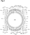
- the movable mirror 11 includes a main body portion 111, a frame portion 112 (electrode support portion), and a pair of connection portions 113.
- the main body portion 111 has a circular shape when viewed from the Z-axis direction.
- the main body portion 111 includes a central portion 114 and an outer edge portion 115.
- the mirror surface 11a having a circular shape is provided on a surface of the central portion 114 on the main surface 12b side by forming a metal film thereon.
- the central portion 114 is formed by a part of the device layer 52.
- the outer edge portion 115 surrounds the central portion 114 when viewed from the Z-axis direction.
- the outer edge portion 115 includes a first main body portion 115a and a first rib portion 115b.
- the first main body portion 115a is formed by a part of the device layer 52.
- the first rib portion 115b is formed at a part of the support layer 51 and the intermediate layer 53.
- the first rib portion 115b is provided on a surface of the first main body portion 115a on the main surface 12b side.
- the first rib portion 115b is formed so that the thickness of the outer edge portion 115 in the Z-axis direction is larger than the thickness of the central portion 114 in the Z-axis direction.
- the first rib portion 115b has a circular ring shape when viewed from the Z-axis direction, and surrounds the mirror surface 11a.
- the first rib portion 115b extends along an outer edge of the main body portion 111 when viewed from the Z-axis direction.
- an outer edge of the first rib portion 115b extends along the outer edge of the main body portion 111 with a predetermined interval from the outer edge of the main body portion 111 when viewed from the Z-axis direction.
- An inner edge of the first rib portion 115b extends along an outer edge of the mirror surface 11a with a predetermined interval from the outer edge of the mirror surface 11a when viewed from the Z-axis direction.
- the frame portion 112 surrounds the main body portion 111 with a predetermined interval from the main body portion 111 when viewed from the Z-axis direction.
- the frame portion 112 has a circular ring shape when viewed from the Z-axis direction.
- the frame portion 112 is disposed along the outer edge of the movable mirror 11 (to constitute the outer edge of the movable mirror 11).
- the frame portion 112 includes a second main body portion 112a and a second rib portion 112b.
- the second main body portion 112a is formed by a part of the device layer 52.
- the second rib portion 112b is formed by a part of the support layer 51 and the intermediate layer 53.
- the second rib portion 112b is provided on a surface of the second main body portion 112a on the main surface 12b side.
- the second rib portion 112b is formed so that the thickness of the frame portion 112 in the Z-axis direction is larger than the thickness of the central portion 114 in the Z-axis direction.
- the second rib portion 112b has a circular ring shape when viewed from the Z-axis direction.
- An outer edge of the second rib portion 112b extends along an outer edge of the frame portion 112 with a predetermined interval from the outer edge of the frame portion 112 when viewed from the Z-axis direction.
- An inner edge of the second rib portion 112b extends along an inner edge of the frame portion 112 with a predetermined interval from the inner edge of the frame portion 112 when viewed from the Z-axis direction.
- the thickness of the second rib portion 112b in the Z-axis direction is the same as the thickness of the first rib portion 115b in the Z-axis direction.
- a width of the second rib portion 112b is wider than a width of the first rib portion 115b when viewed from the Z-axis direction.
- the width of the first rib portion 115b when viewed from the Z-axis direction is a length of the first rib portion 115b in a direction that is perpendicular to an extending direction of the first rib portion 115b, and is a length of the first rib portion 115b in a radial direction of the first rib portion 115b in this embodiment. This is also true of a width of the second rib portion 112b when viewed from the Z-axis direction.
- connection portions 113 connect the main body portion 111 and the frame portion 112.
- the pair of connection portions 113 are respectively disposed on one side and on the other side in the Y-axis direction with respect to the main body portion 111.
- Each of the connection portions 113 includes a third main body portion 113a and a third rib portion 113b.
- the third main body portion 113a is formed by a part of the device layer 52.
- the third main body portion 113a is connected to the first main body portion 115a and the second main body portion 112a.
- the third rib portion 113b is formed by a part of the support layer 51 and the intermediate layer 53.
- the third rib portion 113b is connected to the first rib portion 115b and the second rib portion 112b.
- the third rib portion 113b is provided on a surface of the third main body portion 113a on the main surface 12b side.
- the third rib portion 113b is formed so that the thickness of the connection portion 113 in the Z-axis direction is larger than the thickness of the central portion 114 in the Z-axis direction.
- the thickness of the third rib portion 113b in the Z-axis direction is the same as the thickness of each of the first rib portion 115b and the second rib portion 112b in the Z-axis direction.
- a width of the third rib portion 113b is larger than a width of each of the first rib portion 115b and the second rib portion 112b.
- the width of the third rib portion 113b is a length of the third rib portion 113b along an extending direction of the first rib portion 115b.
- the movable mirror 11 further includes a pair of brackets 116 and a pair of brackets 117.
- the brackets 116 and the brackets 117 are formed by a part of the device layer 52.
- the brackets 116 extend along the Y-axis direction and have a rectangular shape when viewed from the Z-axis direction.
- One of the brackets 116 protrudes from a lateral surface of the frame portion 112 toward one side in the Y-axis direction, and the other bracket 116 protrudes from the lateral surface of the frame portion 112 toward the other side in the Y-axis direction.
- the pair of brackets 116 are disposed on the same central line parallel to the Y-axis direction.
- the brackets 116 are disposed on the first optical function unit 17 side with respect to the center of the main body portion 111.
- the brackets 117 extend along the Y-axis direction, and have a rectangular shape when viewed from the Z-axis direction.
- One of the brackets 117 protrudes from the lateral surface of the frame portion 112 toward the one side in the Y-axis direction, and the other bracket 117 protrudes from the lateral surface of the frame portion 112 toward the other side in the Y-axis direction.
- the pair of brackets 117 are disposed on the same central line parallel to the Y-axis direction.
- the brackets 117 are disposed on the second optical function unit 18 side with respect to the center of the main body portion 111.
- the drive unit 13 includes a first elastic support unit 14, a second elastic support unit 15, and an actuator unit 16.
- a part other than a fourth rib portion 141e, a fifth rib portion 147b, a sixth rib portion 151e, and a seventh rib portion 157b to be described later is formed by a part of the device layer 52.
- Each of the first elastic support unit 14 and the second elastic support unit 15 is connected between the base 12 and the movable mirror 11.
- the first elastic support unit 14 and the second elastic support unit 15 support the movable mirror 11 so that the movable mirror 11 is movable along the Z-axis direction.
- the first elastic support unit 14 includes a pair of levers 141, a link 142, a link 143, a pair of first torsion bars (torsion support portions) 145, a pair of second torsion bars (torsion support portions) 146, and a pair of electrode support portions 147.
- the pair of levers 141 are respectively disposed on both sides of the first optical function unit 17 in the Y-axis direction.
- the levers 141 have a plate shape that extends along a plane perpendicular to the Z-axis direction. In this embodiment, the levers 141 extend along the X-axis direction.
- the link 142 bridges ends 141a of the pair of levers 141 on the movable mirror 11 side.
- the link 142 has a plate shape that extends along a plane perpendicular to the Z-axis direction. Both ends of the link 142 extend along the Y-axis direction.
- An intermediate portion of the link 142 extends along the frame portion 112 and is curved in a convex shape toward a side opposite to the movable mirror 11.
- the link 143 bridges ends 141b of the pair of levers 141 on a side opposite to the movable mirror 11.
- the link 143 has a plate shape that extends along a plane perpendicular to the Z-axis direction, and extends along the Y-axis direction.
- the first optical function unit 17 is an opening that is defined by the pair of levers 141, the link 142, and the link 143.
- the first optical function unit 17 has a rectangular shape when viewed from the Z-axis direction.
- the first optical function unit 17 is a cavity.
- a material having optical transparency with respect to the measurement light L0 may be disposed in the opening that constitutes the first optical function unit 17.
- the pair of first torsion bars 145 respectively bridge a tip end of one of the brackets 116 and one of the ends 141a, and a tip end of the other bracket 116 and the other end 141a. That is, the pair of first torsion bars 145 are respectively connected between the pair of levers 141 and the movable mirror 11.
- the first torsion bars 145 extend along the Y-axis direction.
- the pair of first torsion bars 145 are disposed on the same central line parallel to the Y-axis direction.
- the pair of second torsion bars 146 respectively bridge an end 141b of one of the levers 141 on a side opposite to the movable mirror 11 and the base 12, and an end 141b of the other lever 141 on a side opposite to the movable mirror 11 and the base 12. That is, the pair of second torsion bars 146 are respectively connected between the pair of levers 141 and the base 12.
- the second torsion bars 146 extend along the Y-axis direction.
- the pair of second torsion bars 146 are disposed on the same central line parallel to the Y-axis direction.
- the end 141b of each of the levers 141 is provided with a protrusion 141c that protrudes toward an outer side in the Y-axis direction, and each of the second torsion bars 146 is connected to the protrusion 141c.
- the electrode support portions 147 extend along the Y-axis direction, and have a rectangular shape when viewed from the Z-axis direction.
- One of the electrode support portions 147 extends from an intermediate portion of one of the levers 141 toward a side opposite to the first optical function unit 17.
- the other electrode support portion 147 protrudes from an intermediate portion of the other lever 141 toward a side opposite to the first optical function unit 17.
- the pair of electrode support portions 147 are disposed on the same central line parallel to the Y-axis direction when viewed from the Z-axis direction.
- the second elastic support unit 15 includes a pair of levers 151, a link 152, a link 153, a pair of first torsion bars (torsion support portions) 155, a pair of second torsion bars (torsion support portions) 156, and a pair of electrode support portions 157.
- the pair of levers 151 are respectively disposed on both sides of the second optical function unit 18 in the Y-axis direction.
- the levers 151 have a plate shape that extends along a plane perpendicular to the Z-axis direction. In this embodiment, the levers 151 extend along the X-axis direction.
- the link 152 bridges ends 151a of the pair of levers 151 on the movable mirror 11 side.
- the link 152 has a plate shape that extends along a plane perpendicular to the Z-axis direction. Both ends of the link 152 extend along the Y-axis direction.
- An intermediate portion of the link 152 extends along the frame portion 112 and is curved in a convex shape toward a side opposite to the movable mirror 11.
- the link 153 bridges ends 151b of the pair of levers 151 on a side opposite to the movable mirror 11.
- the link 153 has a plate shape that extends along a plane perpendicular to the Z-axis direction, and extends along the Y-axis direction.
- the second optical function unit 18 is an opening that is defined by the pair of levers 151, the link 152, and the link 153.
- the second optical function unit 18 has a rectangular shape when viewed from the Z-axis direction.
- the second optical function unit 18 is a cavity.
- a material having optical transparency with respect to the measurement light L0 may be disposed in the opening that constitutes the second optical function unit 18.
- the pair of first torsion bars 155 respectively bridge a tip end of one of the brackets 117 and one of the ends 151a, and a tip end of the other bracket 117 and the other end 151a. That is, the pair of first torsion bars 155 are respectively connected between the pair of levers 151 and the movable mirror 11.
- the first torsion bars 155 extend along the Y-axis direction.
- the pair of first torsion bars 155 are disposed on the same central line parallel to the Y-axis direction.
- the pair of second torsion bars 156 respectively bridge an end 151b of one of the levers 151 on a side opposite to the movable mirror 11 and the base 12, and an end 151b of the other lever 151 on a side opposite to the movable mirror 11 and the base 12. That is, the pair of second torsion bars 156 are respectively connected between the pair of levers 151 and the base 12.
- the second torsion bars 156 extend along the Y-axis direction.
- the pair of second torsion bars 156 are disposed on the same central line parallel to the Y-axis direction.
- the end 151b of each of the levers 151 is provided with a protrusion 151c that protrudes toward an outer side in the Y-axis direction, and each of the second torsion bars 156 is connected to the protrusion 151c.
- the electrode support portions 157 extend along the Y-axis direction, and have a rectangular shape when viewed from the Z-axis direction.
- One of the electrode support portions 157 extends from an intermediate portion of one of the levers 151 toward a side opposite to the second optical function unit 18.
- the other electrode support portion 157 protrudes from an intermediate portion of the other lever 151 toward a side opposite to the second optical function unit 18.
- the pair of electrode support portions 157 are disposed on the same central line parallel to the Y-axis direction when viewed from the Z-axis direction.
- the actuator unit 16 moves the movable mirror 11 along the Z-axis direction.
- the actuator unit 16 includes a pair of first fixed comb electrodes 161, a pair of first movable comb electrodes 162, a pair of first fixed comb electrodes 163, a pair of first movable comb electrodes 164, a pair of second fixed comb electrodes 165, and a pair of second movable comb electrodes 166. Positions of the first fixed comb electrodes 161 and 163, and the second fixed comb electrodes 165 are fixed. The first movable comb electrodes 162 and 164, and the second movable comb electrodes 166 move in accordance with movement of the movable mirror 11.
- One of the first fixed comb electrodes 161 is provided on a surface of the device layer 52 of the base 12 which faces one of the electrode support portions 147.
- the other first fixed comb electrode 161 is provided on a surface of the device layer 52 which faces the other electrode support portion 147.
- Each of the first fixed comb electrodes 161 includes a plurality of first fixed comb fingers 161a which extend along a plane perpendicular to the Y-axis direction.
- the first fixed comb fingers 161a are disposed to be aligned with a predetermined interval in the Y-axis direction.
- One of the first movable comb electrodes 162 is provided on a surface of one of the electrode support portions 147 on the other side (the electrode support portion 157 side) in the X-axis direction.
- the other first movable comb electrode 162 is provided on a surface of the other electrode support portion 147 on the other side in the X-axis direction. That is, the pair of first movable comb electrodes 162 are respectively supported by the pair of electrode support portions 147.
- Each of the first movable comb electrodes 162 includes a plurality of first movable comb fingers 162a which extend along a plane perpendicular to the Y-axis direction. The first movable comb fingers 162a are disposed to be aligned with a predetermined interval in the Y-axis direction.
- the plurality of first fixed comb fingers 161a and the plurality of first movable comb fingers 162a are alternately disposed. That is, each of the first fixed comb fingers 161a of one of the first fixed comb electrodes 161 is located between the first movable comb fingers 162a of one of the first movable comb electrodes 162. In the other first fixed comb electrode 161 and the other first movable comb electrode 162, the plurality of first fixed comb fingers 161a and the plurality of first movable comb fingers 162a are alternately disposed.
- each of the first fixed comb fingers 161a of the other first fixed comb electrode 161 is located between the first movable comb fingers 162a of the other first movable comb electrode 162.
- the first fixed comb fingers 161a and the first movable comb fingers 162a which are adjacent to each other face each other in the Y-axis direction.
- a distance between the first fixed comb fingers 161a and the first movable comb fingers 162a which are adjacent to each other is approximately several ⁇ m.
- One of the first fixed comb electrodes 163 is provided on a surface of the device layer 52 of the base 12 which faces one of the electrode support portions 157.
- the other first fixed comb electrode 163 is provided on a surface of the device layer 52 which faces the other electrode support portion 157.
- Each of the first fixed comb electrodes 163 includes a plurality of first fixed comb fingers 163a which extend along a plane perpendicular to the Y-axis direction.
- the first fixed comb fingers 163a are disposed to be aligned with a predetermined interval in the Y-axis direction.
- One of the first movable comb electrodes 164 is provided on a surface of one of the electrode support portions 157 on the one side (the electrode support portion 147 side) in the X-axis direction.
- the other first movable comb electrode 164 is provided on a surface of the other electrode support portion 157 on the one side in the X-axis direction. That is, the pair of first movable comb electrodes 164 are respectively supported by the pair of electrode support portions 157.
- Each of the first movable comb electrodes 164 includes a plurality of first movable comb fingers 164a which extend along a plane perpendicular to the Y-axis direction. The first movable comb fingers 164a are disposed to be aligned with a predetermined interval in the Y-axis direction.
- the plurality of first fixed comb fingers 163a and the plurality of first movable comb fingers 164a are alternately disposed. That is, each of the first fixed comb fingers 163a of one of the first fixed comb electrodes 163 is located between the first movable comb fingers 164a of one of the first movable comb electrodes 164. In the other first fixed comb electrode 163 and the other first movable comb electrode 164, the plurality of first fixed comb fingers 163a and the plurality of first movable comb fingers 164a are alternately disposed.
- each of the first fixed comb fingers 163a of the other first fixed comb electrode 163 is located between the first movable comb fingers 164a of the other first movable comb electrode 164.
- the first fixed comb fingers 163a and the first movable comb fingers 164a which are adjacent to each other face each other in the Y-axis direction.
- a distance between the first fixed comb fingers 163a and the first movable comb fingers 164a which are adjacent to each other is approximately several ⁇ m.
- the pair of second fixed comb electrodes 165 are disposed along an outer edge of the movable mirror 11.
- the pair of second fixed comb electrodes 165 are provided on a surface, which faces an outer surface of the frame portion 112 in the Y-axis direction, of the device layer 52 of the base 12.
- Each of the second fixed comb electrodes 165 includes a plurality of second fixed comb fingers 165a which extend along a plane perpendicular to the X-axis direction.
- the second fixed comb fingers 165a are disposed to be aligned with a predetermined interval in the X-axis direction.
- the pair of second movable comb electrodes 166 are disposed along an outer edge of the movable mirror 11.
- the pair of second movable comb electrodes 166 are provided on the outer surface of the frame portion 112 in the Y-axis direction. That is, the frame portion 112 constitutes an electrode support portion that supports the second movable comb electrodes 166.
- Each of the second movable comb electrodes 166 includes a plurality of second movable comb fingers 166a which extend along a plane perpendicular to the X-axis direction.
- the second movable comb fingers 166a are disposed to be aligned with a predetermined interval in the X-axis direction.
- the plurality of second fixed comb fingers 165a and the plurality of second movable comb fingers 166a are alternately disposed. That is, each of the second fixed comb fingers 165a of one of the second fixed comb electrodes 165 is located between the second movable comb fingers 166a of one of the second movable comb electrodes 166. In the other second fixed comb electrode 165 and the other second movable comb electrode 166, the plurality of second fixed comb fingers 165a and the plurality of second movable comb fingers 166a are alternately disposed.
- each of the second fixed comb fingers 165a of the other second fixed comb electrode 165 is located between the second movable comb fingers 166a of the other second movable comb electrode 166.
- the second fixed comb fingers 165a and the second movable comb fingers 166a which are adjacent to each other face each other in the X-axis direction.
- a distance between the second fixed comb fingers 165a and the second movable comb fingers 166a which are adjacent to each other is approximately several ⁇ m.
- a plurality of electrode pads 121 and 122 are provided in the base 12.
- the electrode pads 121 and 122 are formed on a surface of the device layer 52 in openings 12c formed in the main surface 12b of the base 12 to reach the device layer 52.
- the electrode pads 121 are electrically connected to the first fixed comb electrodes 161, the first fixed comb electrodes 163, or the second fixed comb electrodes 165 through the device layer 52.
- Several pieces of the electrode pads 122 are electrically connected to the first movable comb electrodes 162 or the first movable comb electrodes 164 through the first elastic support unit 14 or the second elastic support unit 15.
- the other electrode pads 122 are electrically connected to the second movable comb electrodes 166 through the first elastic support unit 14 and the frame portion 112 of the movable mirror 11, or through the second elastic support unit 15 and the frame portion 112 of the movable mirror 11.
- Each of the wires 26 bridges each of the electrode pads 121 and 122 and each of the lead pins 25.
- the first fixed comb electrodes 161 and 163, and the first movable comb electrodes 162 and 164 can be used as an electrode for driving. Specifically, when a voltage is applied to between the plurality of electrode pads 121 and the plurality of electrode pads 122 through the plurality of lead pins 25 and the plurality of wires 26, an electrostatic force occurs between the first fixed comb electrodes 161 and the first movable comb electrodes 162 which face each other, and between the first fixed comb electrodes 163 and the first movable comb electrodes 164 which face each other to move the movable mirror 11, for example, toward one side in the Z-axis direction.
- the first torsion bars 145 and 155 and the second torsion bars 146 and 156 in the first elastic support unit 14 and the second elastic support unit 15 are twisted, and an elastic force occurs in the first elastic support unit 14 and the second elastic support unit 15.
- the drive unit 13 functions as an electrostatic actuator.
- the second fixed comb electrodes 165 and the second movable comb electrodes 166 can be used as an electrode for monitoring. Specifically, electrostatic capacitance between the second fixed comb electrodes 165 and the second movable comb electrodes 166 is detected through the plurality of lead pins 25 and the plurality of wires 26, and the plurality of electrode pads 121 and the plurality of electrode pads 122.
- the electrostatic capacitance varies in correspondence with a position of the movable mirror 11 in the Z-axis direction. Accordingly, it is possible to perform feedback control of the position of the movable mirror 11 by adjusting drive vibration (the magnitude, a period, and the like of an application voltage) in correspondence with electrostatic capacitance that is detected.
- the frame portion 112 constitutes an electrode support portion that supports the second movable comb electrodes 166.
- the frame portion 112 includes the second rib portion 112b that is formed so that the thickness of the frame portion 112 in the Z-axis direction is larger than the thickness of the central portion 114 in the Z-axis direction.
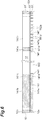
- the thickness of the frame portion 112 in the Z-axis direction is larger than the thickness of the second movable comb fingers 166a in the Z-axis direction (refer to FIG. 5 ). That is, the second rib portion 112b is formed so that the thickness of the frame portion 112 in the Z-axis direction is larger than the thickness of the second movable comb fingers 166a in the Z-axis direction.
- Each of the levers 141 includes a fourth main body portion 141d and a fourth rib portion 141e.
- the fourth main body portion 141d is formed by a part of the device layer 52.
- the fourth rib portion 141e is formed by a part of the support layer 51 and the intermediate layer 53.
- the fourth rib portion 141e is provided on a surface of the fourth main body portion 141d on the main surface 12b side.
- the fourth rib portion 141e has an elongated rectangular shape when viewed from the Z-axis direction.
- the fourth rib portion 141e is formed as follows.
- the fourth rib portion 141e is formed so that the thickness of the lever 141 in the Z-axis direction is larger than the thickness of the first movable comb fingers 162a in the Z-axis direction.
- the fourth rib portion 141e extends along the X-axis direction between the both ends 141a and 141b of the lever 141. That is, in the lever 141, the fourth rib portion 141e extends between a connection position with the first torsion bar 145 and a connection position with the link 143.
- An outer edge of the fourth rib portion 141e in the Y-axis direction extends along an outer edge of the lever 141 in the Y-axis direction with a predetermined interval from the outer edge of the lever 141 when viewed from the Z-axis direction.
- An inner edge of the fourth rib portion 141e in the Y-axis direction extends along an inner edge of the lever 141 in the Y-axis direction with a predetermined interval from the inner edge when viewed from the Z-axis direction.
- Each of the electrode support portions 147 includes a fifth main body portion 147a and a fifth rib portion 147b.
- the fifth main body portion 147a is formed by a part of the device layer 52.
- the fifth main body portion 147a is connected to the fourth main body portion 141d.
- the first movable comb electrodes 162 extend from the fifth main body portion 147a.
- the fifth rib portion 147b is formed by a part of the support layer 51 and the intermediate layer 53.
- the fifth rib portion 147b is formed on a surface of the fifth main body portion 147a on the main surface 12b side.
- the fifth rib portion 147b is connected to the fourth rib portion 141e.
- the fifth rib portion 147b has a rectangular shape when viewed from the Z-axis direction.
- the fifth rib portion 147b is formed as follows.
- the fifth rib portion 147b is formed so that the thickness of the electrode support portion 147 in the Z-axis direction is larger than the thickness of the first movable comb fingers 162a in the Z-axis direction.
- the fifth rib portion 147b extends between both ends of the electrode support portion 147 along the Y-axis direction.
- An edge of the fifth rib portion 147b on one side in the X-axis direction extends along an edge of the electrode support portion 147 on the one side in the X-axis direction with a predetermined interval from the edge on the one side when viewed from the Z-axis direction.
- An edge of the fifth rib portion 147b on the other side in the X-axis direction extends along an edge of the electrode support portion 147 on the other side in the X-axis direction with a predetermined interval from the edge on the other side when viewed from the Z-axis direction.
- the thickness of the fourth rib portion 141e in the Z-axis direction is the same as the thickness of the first rib portion 115b in the Z-axis direction.
- a width of the fourth rib portion 141e (a length in the Y-axis direction) is wider than a width of the first rib portion 115b and is approximately the same as a width of the second rib portion 112b.
- the thickness of the fifth rib portion 147b is approximately the same as the thickness of the fourth rib portion 141e.
- a width of the fifth rib portion 147b (a length in the X-axis direction) is approximately the same as the width of the fourth rib portion 141e, or is slightly smaller than the width of the fourth rib portion 141e.
- each of the first rib portion 115b, the fourth rib portion 141e, and the fifth rib portion 147b in the Z-axis direction is larger than the thickness of the first torsion bar 145 and the second torsion bar 146 in the Z-axis direction.
- the thickness T1 of the electrode support portion 147 in the Z-axis direction and the thickness T2 of the first movable comb finger 162a in the Z-axis direction may satisfy the following Expression (2) to suppress distortion of the electrode support portion 147 that supports the first movable comb electrodes 162 during movement of the movable mirror 11 along the Z-axis direction.
- W1 is a width of the electrode support portions 147 (a length in the X-axis direction)
- C1 is a length of the electrode support portions 147 (a length in the Y-axis direction)
- N1 is the number of the first movable comb fingers 162a included in one piece of the first movable comb electrode 162
- W2 is a width of the first movable comb finger 162a (a length in the Y-axis direction)
- C2 is a length of the first movable comb finger 162a when viewed from the Z-axis direction (a length in the X-axis direction). According to this, it is possible to make the electrode support portions 147 be less likely to be distorted in comparison to the first movable comb electrode 162.
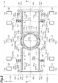
- the electrode support portions 147 and the first movable comb electrodes 162 are disposed to be located on a side opposite to the movable mirror 11 with respect to the center A of the levers 141 in the X-axis direction (an extending direction of the levers 141) to secure a distance between the first fixed comb electrodes 161 and the first movable comb electrodes 162, and the movable mirror 11 (refer to FIG. 2 ).
- Each of the levers 151 includes a sixth main body portion 151d and a sixth rib portion 151e.
- the sixth main body portion 151d is formed by a part of the device layer 52.
- the sixth rib portion 151e is formed by a part of the support layer 51 and an intermediate layer 53.
- the sixth rib portion 151e is provided on a surface of the sixth main body portion 151d on the main surface 12b side.
- the sixth rib portion 151e has an elongated rectangular shape when viewed from the Z-axis direction.
- the sixth rib portion 151e is formed as follows.
- the sixth rib portion 151e is formed so that the thickness of the lever 151 in the Z-axis direction is larger than the thickness of the first movable comb fingers 164a in the Z-axis direction.
- the sixth rib portion 151e extends along the X-axis direction between the both ends 151a and 151b of the lever 151. That is, in the lever 151, the sixth rib portion 151e extends between a connection position with the first torsion bar 155 and a connection position with the link 153.
- An outer edge of the sixth rib portion 151e in the Y-axis direction extends along an outer edge of the lever 151 in the Y-axis direction with a predetermined interval from the outer edge of the lever 151 when viewed from the Z-axis direction.
- An inner edge of the sixth rib portion 151e in the Y-axis direction extends along an inner edge of the lever 151 in the Y-axis direction with a predetermined interval from the inner edge when viewed from the Z-axis direction.
- the sixth rib portion 151e is formed in the same shape as in the fourth rib portion 141e.
- Each of the electrode support portions 157 includes a seventh main body portion 157a and a seventh rib portion 157b.
- the seventh main body portion 157a is formed by a part of the device layer 52.
- the seventh main body portion 157a is connected to the sixth main body portion 151d.
- the first movable comb electrodes 164 extend from the seventh main body portion 157a.
- the seventh rib portion 157b is formed by a part of the support layer 51 and the intermediate layer 53.
- the seventh rib portion 157b is formed on a surface of the seventh main body portion 157a on the main surface 12b side.
- the seventh rib portion 157b is connected to the sixth rib portion 151e.
- the seventh rib portion 157b has a rectangular shape when viewed from the Z-axis direction.
- the seventh rib portion 157b is formed as follows.
- the seventh rib portion 157b is formed so that the thickness of the electrode support portion 157 in the Z-axis direction is larger than the thickness of the first movable comb fingers 164a in the Z-axis direction.
- the seventh rib portion 157b extends between both ends of the electrode support portion 157 along the Y-axis direction.
- An edge of the seventh rib portion 157b on one side in the X-axis direction extends along an edge of the electrode support portion 157 on the one side in the X-axis direction with a predetermined interval from the edge on the one side when viewed from the Z-axis direction.
- An edge of the seventh rib portion 157b on the other side in the X-axis direction extends along an edge of the electrode support portion 157 on the other side in the X-axis direction with a predetermined interval from the edge on the other side when viewed from the Z-axis direction.
- the seventh rib portion 157b is formed in the same shape as in the fifth rib portion 147b.
- the thickness T3 of the electrode support portion 157 in the Z-axis direction and the thickness T4 of the first movable comb finger 164a in the Z-axis direction may satisfy the following Expression (3) to suppress distortion of the electrode support portion 157 that supports the first movable comb electrodes 164 during movement of the movable mirror 11 along the Z-axis direction.
- W3 is a width of the electrode support portions 157 (a length in the X-axis direction)
- C1 is a length of the electrode support portions 157 (a length in the Y-axis direction)
- N2 is the number of the first movable comb fingers 164a included in one piece of the first movable comb electrode 164
- W4 is a width of the first movable comb finger 164a (a length in the Y-axis direction)
- C4 is a length of the first movable comb finger 164a (a length in the X-axis direction).
- the electrode support portions 157 and the first movable comb electrodes 164 are disposed to be located on a side opposite to the movable mirror 11 with respect to the center B of the levers 151 in the X-axis direction (an extending direction of the levers 151) to secure a distance from the first fixed comb electrodes 163 and the first movable comb electrodes 164 to the movable mirror 11 (refer to FIG. 2 ).
- the thickness of the electrode support portion 147 in the Z-axis direction is larger than the thickness of the first movable comb fingers 162a in the Z-axis direction, and the first movable comb electrode 162 is supported by the electrode support portion 147.
- the seventh rib portion 157b is formed, the thickness of the electrode support portion 157 in the Z-axis direction is larger than the thickness of the first movable comb fingers 164a in the Z-axis direction, and the first movable comb electrode 164 is supported by the electrode support portion 157.
- the thickness of the frame portion 112 in the Z-axis direction is larger than the thickness of the second movable comb fingers 166a in the Z-axis direction, and the second movable comb electrode 166 is supported by the frame portion 112. Accordingly, it is possible to suppress distortion of the electrode support portions 147 and 157, and the frame portion 112 which respectively support the first movable comb electrodes 162 and 164, and the second movable comb electrode 166 during movement of the movable mirror 11 along the Z-axis direction.
- the first movable comb electrodes 162 and 164, and the second movable comb electrode 166 it is possible to cause the first movable comb electrodes 162 and 164, and the second movable comb electrode 166 to move integrally with the movable mirror 11, and it is possible to suppress fluctuation of an interval between the first movable comb fingers 162a and the first fixed comb fingers 161a which are adjacent to each other, an interval between the first movable comb fingers 164a and the first fixed comb fingers 163a which are adjacent to each other, and an interval between the second movable comb fingers 166a and the second fixed comb fingers 165a which are adjacent to each other.
- the optical device 10 it is possible to suppress fluctuation of an interval between the first movable comb electrodes 162 and 164, and the first fixed comb electrodes 161 and 163 due to the electrode support portion 147 that extends from the lever 141, and the electrode support portion 157 that extends from the lever 151.
- the first movable comb electrode 162 is located on a side opposite to the movable mirror 11 with respect to the center A of the lever 141 in the X-axis direction. Accordingly, even when the movable mirror 11 greatly moves along the Z-axis direction, the first movable comb fingers 162a are less likely to deviate from a region between the first fixed comb fingers 161a which are adjacent to each other.
- the first movable comb electrode 164 is located on a side opposite to the movable mirror 11 with respect to the center B of the lever 151 in the X-axis direction.
- the first movable comb fingers 164a are less likely to deviate from a region between the first fixed comb fingers 163a which are adjacent to each other. Accordingly, it is possible to allow an electrostatic force to occur between the first fixed comb electrodes 161 and the first movable comb electrodes 162, and between the first fixed comb electrodes 163 and the first movable comb electrodes 164 over the entirety of a movable range of the movable mirror 11.
- the electrode support portions 147 and the first movable comb electrodes 162 are located between points C and C which divide the lever 141 into three parts in the X-axis direction.
- the electrode support portions 157 and the first movable comb electrodes 164 are located between points D and D which divide the lever 151 into three parts in the X-axis direction.
- the lever 141 includes the fourth rib portion 141e that is formed so that the thickness of the lever 141 in the Z-axis direction is larger than the thickness of the first movable comb fingers 162a in the Z-axis direction.
- the lever 151 includes the sixth rib portion 151e that is formed so that the thickness of the lever 151 in the Z-axis direction is larger than the thickness of the first movable comb fingers 164a in the Z-axis direction. Accordingly, it is possible to more reliably suppress fluctuation of the interval between the first movable comb electrodes 162 and 164 and, the first fixed comb electrodes 161 and 163, and thus it is possible to further enhance the reliability.
- the thickness T1 of the electrode support portion 147 in the Z-axis direction, and the thickness T2 of the first movable comb finger 162a in the Z-axis direction satisfy Expression (2) described above.
- the thickness T3 of the electrode support portion 157 in the Z-axis direction and the thickness T4 of the first movable comb finger 164a in the Z-axis direction satisfy Expression (3) described above. Accordingly, it is possible to more reliably suppress fluctuation of the interval between the first movable comb electrodes 162 and 164, and the first fixed comb electrodes 161 and 163.
- the electrode support portion (frame portion 112) is provided in the movable mirror 11 to be disposed along the outer edge of the movable mirror 11. Accordingly, it is possible to secure a distance from a connection position with respect to the base 12 in the first elastic support unit 14 and the second elastic support unit 15 to the second movable comb electrode 166. As a result, a variation of electrostatic capacitance between the second fixed comb electrode 165 and the second movable comb electrode 166 is great, and thus it is possible to easily and reliably detect a position of the movable mirror 11.
- an electrode support portion is constituted by the frame portion 112. Accordingly, it is possible to suppress fluctuation of an interval between the second movable comb electrode 166 and the second fixed comb electrode 165 due to the frame portion 112 that surrounds the main body portion 111.
- the movable mirror 11 includes the main body portion 111, the frame portion 112 that surrounds the main body portion with a predetermined interval from the main body portion 111 when viewed from the Z-axis direction, and the connection portion 113 that connects the main body portion 111 and the frame portion 112.
- a sectional force (bending moment) from the first torsion bars 145 and 155 is less likely to be transmitted to the main body portion 111, and thus it is possible to suppress distortion of the main body portion 111 during movement of the movable mirror 11 along the Z-axis direction.
- the thickness of the outer edge portion 115 in the Z-axis direction is larger than the thickness of the central portion 114 in the Z-axis direction. Accordingly, it is possible to suppress distortion of the main body portion 111 during movement of the movable mirror 11 along the Z-axis direction.
- the second rib portion 112b is formed, the thickness of the frame portion 112 in the Z-axis direction is larger than the thickness of the central portion 114 in the Z-axis direction. Accordingly, it is possible to suppress distortion of the frame portion 112 during movement of the movable mirror 11 along the Z-axis direction, and it is possible to suppress distortion of the main body portion 111 which is caused by the distortion of the frame portion 112.
- the optical device 10 may be constituted as in a first modification example illustrated in FIG. 7 .
- a pair of the electrode support portions 147 are provided in each of the levers 141.
- the first movable comb electrode 162 is provided in each of the electrode support portions 147.
- the pair of electrode support portions 147 are formed as follows.
- the pair of electrode support portions 147 are disposed to be aligned along the X-axis direction.
- One of the electrode support portions 147 is disposed at the same position as in the electrode support portion 147 in the embodiment.
- the other electrode support portion 147, and the first movable comb electrode 162 supported by the other electrode support portion 147 are located on the movable mirror 11 side with respect to the center A of the lever 141 in the X-axis direction. More specifically, the other electrode support portion 147 and the first movable comb electrode 162 supported by the other electrode support portion 147 are located on the movable mirror 11 side in comparison to the points C and C which divide the lever 141 into three parts in the X-axis direction.
- a pair of the electrode support portions 157 are provided in each of the levers 151.
- the first movable comb electrode 164 is provided in each of the electrode support portions 157.
- the pair of electrode support portions 157 are formed as follows.
- the pair of electrode support portions 157 are disposed to be aligned along the X-axis direction.
- One of the electrode support portions 157 is disposed at the same position as in the electrode support portion 157 in the embodiment.
- the other electrode support portion 157, and the first movable comb electrode 164 supported by the other electrode support portion 157 are located on the movable mirror 11 side with respect to the center A of the lever 151 in the X-axis direction.
- the other electrode support portion 157 and the first movable comb electrode 164 supported by the other electrode support portion 157 are located on the movable mirror 11 side in comparison to the points D and D which divide the lever 151 into three parts in the X-axis direction.
- the other first movable comb electrode 162 is located on the movable mirror 11 side with respect to the center A of the lever 141 in the X-axis direction. According to this, it is possible to secure a distance from a connection position with respect to the base 12 in the first elastic support unit 14 to the other first movable comb electrode 162.
- the other first movable comb electrode 164 is located on the movable mirror 11 side with respect to the center B of the lever 151 in the X-axis direction.
- the pair of the electrode support portions 147 and the pair of the electrode support portions 157 are disposed to be aligned along the X-axis direction. According to this, a plurality of the electrode support portions 147 and 157 are provided, and thus it is possible to secure the driving force.
- distortion of the electrode support portions 147 and 157 which support the first movable comb electrodes 162 and 164 is suppressed by increasing the thickness of the electrode support portions 147 and 157 instead of a width thereof, and thus the plurality of electrode support portions 147 and 157 can be disposed to be aligned along the X-axis direction.
- Three or more electrode support portions may be provided in one piece of the lever 141. This is also true of the lever 151.
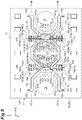
- the optical device 10 may be constituted as in a second modification example illustrated in FIG. 8 .
- the first elastic support unit 14 includes a pair of levers 141, a link 142, a link 143, a pair of first torsion bars 145, a pair of second torsion bars 146, a pair of second levers 171, a link 172, and a pair of third torsion bars 173.
- an end 141b has a shape that is curved toward the first optical function unit 17 side.
- the pair of second levers 171 are respectively disposed on both sides of the levers 141 in the Y-axis direction.
- Each of the second levers 171 has a plate shape that extends along a plane perpendicular to the Z-axis direction, and extends along each of the levers 141.
- the link 172 bridges ends 171a of the pair of second levers 171 on a side opposite to the movable mirror 11.
- the link 172 has a plate shape that extends along a plane perpendicular to the Z-axis direction, and extends along the Y-axis direction.
- the link 172 is disposed on a side opposite to the first optical function unit 17 with respect to the link 143, and extends along the link 143.
- the pair of second torsion bars 146 respectively bridge the end 141b of one of the levers 141 and the end 171a of one of the second levers 171, and the end 141b of the other lever 141 and the end 171a of the other second lever 171.
- the pair of third torsion bars 173 respectively bridge an end 171b on the movable mirror 11 side in one of the second levers 171 and the base 12, and an end 171b on the movable mirror 11 side in the other second lever 171 and the base 12.
- a first movable comb electrode 162 including a plurality of first movable comb fingers 162a is provided on a surface of the link 172 on a side opposite to the first optical function unit 17. That is, the link 172 constitutes an electrode support portion that supports the first movable comb electrode 162.
- Each of the links 172 includes an eighth main body portion 172a and an eighth rib portion 172b.
- the eighth main body portion 172a is formed by a part of the device layer 52.
- the first movable comb electrode 162 extends from the eighth main body portion 172a.
- the eighth rib portion 172b is formed by a part of the support layer 51 and the intermediate layer 53.
- the eighth rib portion 172b is provided on a surface of the eighth main body portion 172a on the main surface 12b side.
- the eighth rib portion 172b is formed so that the thickness of the link 172 in the Z-axis direction is larger than the thickness of the first movable comb fingers 162a in the Z-axis direction.
- the eighth rib portion 172b extends between both ends of the link 172 along the Y-axis direction.
- An edge of the eighth rib portion 172b on one side in the X-axis direction extends along an edge of the link 172 on the one side in the X-axis direction with a predetermined interval from the edge when viewed from the Z-axis direction.
- An edge of the eighth rib portion 172b on the other side in the X-axis direction extends along an edge of the link 172 on the other side in the X-axis direction with a predetermined interval from the edge when viewed from the Z-axis direction.
- the second elastic support unit 15 includes a pair of levers 151, a link 152, a link 153, a pair of first torsion bars 155, a pair of second torsion bars 156, a pair of second levers 181, a link 182, and a pair of third torsion bars 183.
- an end 151b has a shape that is curved toward the second optical function unit 18 side.
- the pair of second levers 181 are respectively disposed on both sides of the levers 151 in the Y-axis direction.
- Each of the second levers 181 has a plate shape that extends along a plane perpendicular to the Z-axis direction, and extends along each of the levers 151.
- the link 182 bridges ends 181a of the pair of second levers 181 on a side opposite to the movable mirror 11.
- the link 182 has a plate shape that extends along a plane perpendicular to the Z-axis direction, and extends along the Y-axis direction.
- the link 182 is disposed on a side opposite to the second optical function unit 18 with respect to the link 153, and extends along the link 153.
- the pair of second torsion bars 156 respectively bridge the end 151b of one of the levers 151 and the end 181a of one of the second levers 181, and the end 151b of the other lever 151 and the end 181a of the other second lever 181.
- the pair of third torsion bars 183 respectively bridge an end 181b on the movable mirror 11 side in one of the second levers 181 and the base 12, and an end 181b on the movable mirror 11 side in the other second lever 181 and the base 12.
- a first movable comb electrode 164 including a plurality of first movable comb fingers 164a is provided on a surface of the link 182 on a side opposite to the second optical function unit 18. That is, the link 182 constitutes an electrode support portion that supports the first movable comb electrode 164.
- Each of the links 182 includes a ninth main body portion 182a and a ninth rib portion 182b.
- the ninth main body portion 182a is formed by a part of the device layer 52.
- the first movable comb electrode 164 extends from the ninth main body portion 182a.
- the ninth rib portion 182b is formed by a part of the support layer 51 and the intermediate layer 53.
- the ninth rib portion 182b is provided on a surface of the ninth main body portion 182a on the main surface 12b side.
- the ninth rib portion 182b is formed so that the thickness of the link 182 in the Z-axis direction is larger than the thickness of the first movable comb fingers 164a in the Z-axis direction.
- the ninth rib portion 182b extends between both ends of the link 182 along the Y-axis direction.
- An edge of the ninth rib portion 182b on one side in the X-axis direction extends along an edge of the link 182 on the one side in the X-axis direction with a predetermined interval from the edge when viewed from the Z-axis direction.
- An edge of the ninth rib portion 182b on the other side in the X-axis direction extends along an edge of the link 182 on the other side in the X-axis direction with a predetermined interval from the edge when viewed from the Z-axis direction.
- the second modification example as in the embodiment, it is possible to suppress fluctuation of an interval between the first movable comb electrodes 162 and 164 and the second movable comb electrode 166, and the first fixed comb electrodes 161 and 163 and the second fixed comb electrode 165, and it is possible to enhance the reliability.
- the optical device 10 may be constituted as in a third modification example illustrated in FIG. 9 .
- the second fixed comb electrode 165 and the second movable comb electrode 166 are not provided.
- the frame portion 112 has an octagonal ring shape when viewed from the Z-axis direction
- the second rib portion 112b has an octagonal ring shape when viewed from the Z-axis direction.
- the movable mirror 11 includes one bracket 116 and one bracket 117.
- the bracket 116 is provided on a surface of the frame portion 112 on the first optical function unit 17 side to protrude toward the first optical function unit 17 side.
- the bracket 117 is provided on a surface of the frame portion 112 on the second optical function unit 18 side to protrude toward the second optical function unit 18 side.
- the first elastic support unit 14 includes a pair of levers 141, a link 142, a pair of first torsion bars 145, a pair of second torsion bars 146, a pair of brackets 174, a pair of extending portions 175, a pair of brackets 176, a link 177, and a pair of non-linearity mitigation springs 178.
- the pair of levers 141 respectively extend from the movable mirror 11 side to both sides of the first optical function unit 17 in the Y-axis direction along a plane that is perpendicular to the Z-axis direction.
- Each of the levers 141 includes a first portion 141f that is disposed on the movable mirror 11 side, and a second portion 141g that is disposed on a side opposite to the movable mirror 11 with respect to the first portion 141f.
- the first portions 141f obliquely extend to be spaced away from each other as going away from the movable mirror 11.
- the second portion 141g extends along the X-axis direction.
- the pair of brackets 174 are respectively provided on surfaces of the first portions 141f on the movable mirror 11 side to protrude toward the movable mirror 11 side.
- the brackets 174 have a shape curved in a crank shape toward the same side when viewed from the Z-axis direction.
- the extending portions 175 have a rectangular shape when viewed from the Z-axis direction.
- One of the extending portions 175 extends between one of the levers 141 and the movable mirror 11, and protrudes to an outer side in comparison to the movable mirror 11 in the Y-axis direction.
- the other extending portion 175 extends between the other lever 141 and the movable mirror 11, and protrudes to an outer side in comparison to the movable mirror 11 in the Y-axis direction.
- the pair of extending portions 175 are disposed on the same central line parallel to the Y-axis direction when viewed from the Z-axis direction.
- a first movable comb electrode 162 including a plurality of first movable comb fingers 162a is provided on surfaces of the extending portions 175 on both sides in the X-axis direction. That is, the extending portions 175 constitute an electrode support portion that supports the first movable comb electrodes 162.
- Each of the extending portions 175 includes a tenth main body portion 175a and a tenth rib portion 175b.
- the tenth main body portion 175a is formed by a part of the device layer 52.
- the first movable comb electrode 162 extends from the tenth main body portion 175a.
- the tenth rib portion 175b is formed by a part of the support layer 51 and the intermediate layer 53.
- the tenth rib portion 175b is provided on a surface of the tenth main body portion 175a on the main surface 12b side.
- the tenth rib portion 175b is formed so that the thickness of the extending portion 175 in the Z-axis direction is larger than the thickness of the first movable comb fingers 162a in the Z-axis direction.
- the tenth rib portion 175b extends between both ends of the extending portion 175 along the Y-axis direction.
- An edge of the tenth rib portion 175b on one side in the X-axis direction extends along an edge of the extending portion 175 on the one side in the X-axis direction with a predetermined interval from the edge when viewed from the Z-axis direction.
- An edge of the tenth rib portion 175b on the other side in the X-axis direction extends along an edge of the extending portion 175 on the other side in the X-axis direction with a predetermined interval from the edge when viewed from the Z-axis direction.
- the pair of brackets 176 are respectively provided on surfaces of the extending portions 175 on the first optical function unit 17 side to protrude toward the first optical function unit 17 side.
- the brackets 176 have a shape that is curved in a crank shape to the same side (however, a side opposite to each of the brackets 174) when viewed from the Z-axis direction.
- a tip end of one of the brackets 176 faces a tip end of one of the brackets 174 in the Y-axis direction.
- a tip end of the other bracket 176 faces a tip end of the other bracket 174 in the Y-axis direction.
- the link 177 bridges inner ends of the pair of extending portions 175.
- the link 177 has an approximately U-shape that is opened toward the movable mirror 11 side when viewed from the Z-axis direction.
- the link 177 faces the bracket 116 of the movable mirror 11 in the Y-axis direction.
- the link 177 includes a pair of side portions 177a which extend in the X-axis direction and face each other in the Y-axis direction, and the bracket 116 is disposed between the pair of side portions 177a.
- the pair of first torsion bars 145 respectively bridge a tip end of one of the brackets 174 and a tip end of one of the brackets 176, and a tip end of the other bracket 174 and a tip end of the other bracket 176.
- the pair of second torsion bars 146 respectively bridge an end 141b of one of the levers 141 and the base 12, and an end 141b of the other lever 141 and the base 12.
- the pair of non-linearity mitigation springs 178 are respectively disposed on one side and on the other side in the Y-axis direction with respect to the bracket 116.
- the non-linearity mitigation springs 178 are connected to the movable mirror 11 through the bracket 116, and are respectively connected to the first torsion bars 145 through the link 177, the extending portions 175, and the brackets 176. That is, the non-linearity mitigation springs 178 are connected between the movable mirror 11 and the first torsion bars 145.
- Each of the non-linearity mitigation springs 178 includes a pair of plate-shaped portions 178a which bridge the bracket 116 and the pair of side portions 177a of the link 177.
- the plate-shaped portions 178a have a flat plate shape perpendicular to the X-axis direction.
- the pair of plate-shaped portions 178a face each other in the X-axis direction.
- the plate-shaped portion 178a located on one side in the X-axis direction is disposed along one plane perpendicular to the X-axis direction
- the plate-shaped portion 178a located on the other side in the X-axis direction is disposed along another plane perpendicular to the X-axis direction.
- a length of each of the plate-shaped portions 178a (a length in the Y-axis direction) is longer than a length of the first torsion bars 145 and a length of the second torsion bars 146.
- a width of each of the plate-shaped portions 178a (a length in the X-axis direction) is narrower than a width of the first torsion bars 145 and a width of the second torsion bars 146.
- the non-linearity mitigation springs 178 are constituted so that a deformation amount of the non-linearity mitigation springs 178 around the Y-axis direction is smaller than a deformation amount of each of the first torsion bars 145 and the second torsion bars 146 around the Y-axis direction, and a deformation amount of the non-linearity mitigation springs 178 in the X-axis direction is larger than a deformation amount of each of the first torsion bars 145 and the second torsion bars 146 in the X-axis direction in a state in which the movable mirror 11 has moved in the Z-axis direction.
- the deformation amount of the first torsion bars 145, the second torsion bars 146, and the non-linearity mitigation springs 178 around the Y-axis direction represents, for example, an absolute value of a twist amount (a twist angle).
- the deformation amount of the first torsion bars 145, the second torsion bars 146, and the non-linearity mitigation springs 178 in the X-axis direction represents, for example, an absolute value of a bending amount.
- a length of the plate-shaped portion 178a represents a length of the plate-shaped portion 178a excluding the widened portion
- a width of the plate-shaped portion 178a represents a width of the plate-shaped portion 178a excluding the widened portion.
- the second elastic support unit 15 includes a pair of levers 151, a link 152, a pair of first torsion bars 155, a pair of second torsion bars 156, a pair of brackets 184, a pair of extending portions 185, a pair of brackets 186, a link 187, and a pair of non-linearity mitigation springs 188.
- the pair of levers 151 respectively extend from the movable mirror 11 side to both sides of the second optical function unit 18 in the Y-axis direction along a plane that is perpendicular to the Z-axis direction.
- Each of the levers 151 includes a first portion 151f that is disposed on the movable mirror 11 side, and a second portion 151g that is disposed on a side opposite to the movable mirror 11 with respect to the first portion 151f.
- the first portions 151f obliquely extend to be spaced away from each other as going away from the movable mirror 11.
- the second portion 151g extends along the X-axis direction.
- the pair of brackets 184 are respectively provided on surfaces of the first portions 151f on the movable mirror 11 side to protrude toward the movable mirror 11 side.
- the brackets 184 have a shape curved in a crank shape toward the same side (however, a side opposite to the brackets 174) when viewed from the Z-axis direction.
- the extending portions 185 have a rectangular shape when viewed from the Z-axis direction.
- One of the extending portions 185 extends between one of the levers 151 and the movable mirror 11, and protrudes to an outer side in comparison to the movable mirror 11 in the Y-axis direction.
- the other extending portion 185 extends between the other lever 151 and the movable mirror 11, and protrudes to an outer side in comparison to the movable mirror 11 in the Y-axis direction.
- the pair of extending portions 185 are disposed on the same central line parallel to the Y-axis direction when viewed from the Z-axis direction.
- a first movable comb electrode 164 including a plurality of first movable comb fingers 164a is provided on surfaces of the extending portions 185 on both sides in the X-axis direction. That is, the extending portions 185 constitute an electrode support portion that supports the first movable comb electrodes 164.
- Each of the extending portions 185 includes an eleventh main body portion 185a and an eleventh rib portion 185b.
- the eleventh main body portion 185a is formed by a part of the device layer 52.
- the first movable comb electrode 164 extends from the eleventh main body portion 185a.
- the eleventh rib portion 185b is formed by a part of the support layer 51 and the intermediate layer 53.
- the eleventh rib portion 185b is provided on a surface of the eleventh main body portion 185a on the main surface 12b side.
- the eleventh rib portion 185b is formed so that the thickness of the extending portion 185 in the Z-axis direction is larger than the thickness of the first movable comb fingers 164a in the Z-axis direction.
- the eleventh rib portion 185b extends between both ends of the extending portion 185 along the Y-axis direction.
- An edge of the eleventh rib portion 185b on one side in the X-axis direction extends along an edge of the extending portion 185 on the one side in the X-axis direction with a predetermined interval from the edge when viewed from the Z-axis direction.
- An edge of the eleventh rib portion 185b on the other side in the X-axis direction extends along an edge of the extending portion 185 on the other side in the X-axis direction with a predetermined interval from the edge when viewed from the Z-axis direction.
- the pair of brackets 186 are respectively provided on surfaces of the extending portions 185 on the second optical function unit 18 side to protrude toward the second optical function unit 18 side.
- the brackets 186 have a shape that is curved in a crank shape to the same side (however, a side opposite to each of the brackets 184) when viewed from the Z-axis direction.
- a tip end of one of the brackets 186 faces a tip end of one of the brackets 184 in the Y-axis direction.
- a tip end of the other bracket 186 faces a tip end of the other bracket 184 in the Y-axis direction.
- the link 187 bridges inner ends of the pair of extending portions 185.
- the link 187 has an approximately U-shape that is opened toward the movable mirror 11 side when viewed from the Z-axis direction.
- the link 187 faces the bracket 117 of the movable mirror 11 in the Y-axis direction. More specifically, the link 187 includes a pair of side portions 187a which extend in the X-axis direction and face each other in the Y-axis direction, and the bracket 117 is disposed between the pair of side portions 187a.
- the pair of first torsion bars 155 respectively bridge a tip end of one of the brackets 184 and a tip end of one of the brackets 186, and a tip end of the other bracket 184 and a tip end of the other bracket 186.
- the pair of second torsion bars 156 respectively bridge an end 151b of one of the levers 151 and the base 12, and an end 151b of the other lever 151 and the base 12.
- the pair of non-linearity mitigation springs 188 are respectively disposed on one side and on the other side in the Y-axis direction with respect to the bracket 117.
- the non-linearity mitigation springs 188 are connected to the movable mirror 11 through the bracket 117, and are respectively connected to the first torsion bars 155 through the link 187, the extending portions 185, and the brackets 186. That is, the non-linearity mitigation springs 188 are connected between the movable mirror 11 and the first torsion bars 155.
- Each of the non-linearity mitigation springs 188 includes a pair of plate-shaped portions 188a which bridge the bracket 117 and the pair of side portions 187a of the link 187.
- the plate-shaped portions 188a have a flat plate shape perpendicular to the X-axis direction.
- the pair of plate-shaped portions 188a face each other in the X-axis direction.
- the plate-shaped portion 188a located on one side in the X-axis direction is disposed along one plane perpendicular to the X-axis direction
- the plate-shaped portion 188a located on the other side in the X-axis direction is disposed along another plane perpendicular to the X-axis direction.
- the plate-shaped portions 188a are formed in the same shape as in the plate-shaped portions 178a.
- a length of each of the plate-shaped portions 188a is longer than a length of the first torsion bars 155 and a length of the second torsion bars 156.
- a width of each of the plate-shaped portions 188a is narrower than a width of the first torsion bars 155 and a width of the second torsion bars 156.
- the non-linearity mitigation springs 188 are constituted so that a deformation amount of the non-linearity mitigation springs 188 around the Y-axis direction is smaller than a deformation amount of each of the first torsion bars 155 and the second torsion bars 156 around the Y-axis direction, and a deformation amount of the non-linearity mitigation springs 188 in the X-axis direction is larger than a deformation amount of each of the first torsion bars 155 and the second torsion bars 156 in the X-axis direction in a state in which the movable mirror 11 has moved in the Z-axis direction.
- Each of the first optical function unit 17 and the second optical function unit 18 is a light passage opening that is formed in the SOI substrate 50.
- Each of the first optical function unit 17 and the second optical function unit 18 has a circular shape when viewed from the Z-axis direction.
- the third modification example as in the embodiment, it is possible to suppress fluctuation of the interval between the first movable comb electrodes 162 and 164, and the first fixed comb electrodes 161 and 163, and it is possible to enhance the reliability.
- the first elastic support unit 14 includes the non-linearity mitigation springs 178 and the second elastic support unit 15 includes the non-linearity mitigation springs 188, it is possible to suppress non-linearity from occurring in twist deformation of the first torsion bars 145 and 155 and the second torsion bars 146 and 156.
- the non-linearity mitigation springs 178 and 188 are provided as described above, it is possible to suppress fluctuation of the interval between the first movable comb electrodes 162 and 164 and the first fixed comb electrodes 161 and 163.
- the optical device 10 may be constituted as in a fourth modification example illustrated in FIG. 10 .
- the fourth modification example is different from the third modification example in the following configuration.
- the first movable comb electrode 162 is disposed along the first portions 141f in the pair of levers 141 and the link 142. That is, the pair of levers 141 and the link 142 constitute an electrode support portion that supports the first movable comb electrode 162.
- the pair of levers 141 and the link 142 may be noted as an electrode support portion 179.
- the first movable comb electrode 164 is disposed along the first portions 151f in the pair of levers 151, and the link 152. That is, the pair of levers 151 and the link 152 constitute an electrode support portion that supports the first movable comb electrode 164.
- the pair of levers 141 and the link 142 may be noted as an electrode support portion 189.
- a pair of intermediate portions 175A are provided instead of the pair of extending portions 175.
- the intermediate portions 175A are respectively connected to the levers 141 through the brackets 174 and 176, and the first torsion bars 145, and are connected to the bracket 116 through the link 177 and the non-linearity mitigation springs 178.
- a pair of intermediate portions 185A are provided instead of the pair of extending portions 185.
- the intermediate portions 185A are respectively connected to the levers 151 through the brackets 184 and 186, and the first torsion bars 155, and are connected to the bracket 117 through the link 187 and the non-linearity mitigation springs 188.
- the first optical function unit 17 When viewed from the Z-axis direction, the first optical function unit 17 is disposed on one side of the movable mirror 11 in the Y-axis direction, and the second optical function unit 18 is disposed on the other side of the movable mirror 11 in the Y-axis direction.
- a first movable comb electrode 162 including a plurality of first movable comb fingers 162a is provided on a surface of the electrode support portion 179 on a side opposite to the movable mirror 11.
- Each of the electrode support portions 179 includes a twelfth main body portion 179a and a twelfth rib portion 179b.
- the twelfth main body portion 179a is formed by a part of the device layer 52.
- the first movable comb electrode 162 extends from the twelfth main body portion 179a.
- the twelfth rib portion 179b is formed by a part of the support layer 51 and the intermediate layer 53.
- the twelfth rib portion 179b is provided on a surface of the twelfth main body portion 179a on the main surface 12b side.
- the twelfth rib portion 179b is formed so that the thickness of the electrode support portion 179 in the Z-axis direction is larger than the thickness of the first movable comb fingers 162a in the Z-axis direction.
- the twelfth rib portion 179b extends between both ends of the electrode support portions 179.
- An edge of the twelfth rib portion 179b on one side in the X-axis direction extends along an edge of the electrode support portion 179 on the one side in the X-axis direction with a predetermined interval from the edge when viewed from the Z-axis direction.
- An edge of the twelfth rib portion 179b on the other side in the X-axis direction extends along an edge of the electrode support portion 179 on the other side in the X-axis direction with a predetermined interval from the edge when viewed from the Z-axis direction.
- a first movable comb electrode 164 including a plurality of first movable comb fingers 164a is provided on a surface of the electrode support portion 189 on a side opposite to the movable mirror 11.
- Each of the electrode support portions 189 includes a thirteenth main body portion 189a and a thirteenth rib portion 189b.
- the thirteenth main body portion 189a is formed by a part of the device layer 52.
- the first movable comb electrode 164 extends from the thirteenth main body portion 189a.
- the thirteenth rib portion 189b is formed by a part of the support layer 51 and the intermediate layer 53.
- the thirteenth rib portion 189b is provided on a surface of the thirteenth main body portion 189a on the main surface 12b side.
- the thirteenth rib portion 189b is formed so that the thickness of the electrode support portion 189 in the Z-axis direction is larger than the thickness of the first movable comb fingers 164a in the Z-axis direction.
- the thirteenth rib portion 189b extends between both ends of the electrode support portions 189.
- An edge of the thirteenth rib portion 189b on one side in the X-axis direction extends along an edge of the electrode support portion 189 on the one side in the X-axis direction with a predetermined interval from the edge when viewed from the Z-axis direction.
- An edge of the thirteenth rib portion 189b on the other side in the X-axis direction extends along an edge of the electrode support portion 189 on the other side in the X-axis direction with a predetermined interval from the edge when viewed from the Z-axis direction.
- the fourth modification example as in the embodiment, it is possible to suppress fluctuation of the interval between the first movable comb electrodes 162 and 164, and the first fixed comb electrodes 161 and 163, and it is possible enhance to the reliability. Particularly, in the fourth modification example, it is possible to suppress fluctuation of the interval between the first movable comb electrodes 162 and 164, and the first fixed comb electrodes 161 and 163 by the electrode support portions 179 and 189.
- the optical device 10 may be constituted as in a fifth modification example illustrated in FIG. 11 .
- the frame portion 112 and the connection portion 113 are not provided, and the brackets 116 and 117 are directly connected to the main body portion 111.
- a pair of second movable comb electrodes 166 are provided on an outer surface of the outer edge portion 115 of the main body portion 111 in the Y-axis direction. That is, in the fifth modification example, the outer edge portion 115 constitutes an electrode support portion that supports the second movable comb electrodes 166.
- the outer edge portion 115 includes the first rib portion 115b that is formed so that the thickness of the outer edge portion 115 in the Z-axis direction is larger than the thickness of the central portion 114 in the Z-axis direction.
- the fifth modification example as in the embodiment, it is possible to suppress fluctuation of an interval between the first movable comb electrodes 162 and 164 and the second movable comb electrode 166, and the first fixed comb electrodes 161 and 163 and the second fixed comb electrode 165, and it is possible enhance to the reliability.
- the first fixed comb electrodes 161 and 163 and the first movable comb electrodes 162 and 164 are described to be used as an electrode for driving
- the second fixed comb electrode 165 and the second movable comb electrode 166 (hereinafter, noted as a second electrode) are described to be used as an electrode for monitoring
- the first electrode may be used as the electrode for monitoring
- the second electrode may be used as the electrode for driving.
- the second electrode may be omitted, and only the first electrode may be provided.
- the first electrode may be used as the electrode for driving, or may be used as an electrode for driving and monitoring.
- the first electrode may be omitted, and only the second electrode may be provided.
- the second electrode may be used as the electrode for driving, or may be used as an electrode for driving and monitoring.
- each of the main body portion 111 and the mirror surface 11a may have any shape such as a rectangular shape and an octagonal shape when viewed from the Z-axis direction.
- the frame portion 112 may have any ring shape such as a rectangular ring shape and an octagonal ring shape when viewed from the Z-axis direction.
- Each of the first rib portion 115b, the second rib portion 112b, the third rib portion 113b, the fourth rib portion 141e, the fifth rib portion 147b, the sixth rib portion 151e, and the seventh rib portion 157b may be formed in any shape.
- the rib portions may extend obliquely with respect to X-axis direction or the Y-axis direction, or may extend in a zigzag shape.
- the arrangement, the number, the length, the width, and the thickness of the rib portions may be arbitrarily set. At least one of the rib portions may be omitted.
- first rib portion 115b is provided on a surface of the first main body portion 115a on the main surface 12b side, but the first rib portion 115b may be provided on a surface of the first main body portion 115a on the main surface 12a side. This is also true of other rib portions.
- the shape of the first torsion bars 145 and 155, and the second torsion bars 146 and 156 is not limited, and may be any shape such as a rod shape.
- Each of the first optical function unit 17 and the second optical function unit 18 may have any shape such as a circular shape and an octagonal shape when viewed from the Z-axis direction.
- the optical device 10 may include a movable unit provided with another optical function unit other than the mirror surface 11a instead of the movable mirror 11. Examples of the other optical function unit include a lens.
- the actuator unit 16 is not limited to the electrostatic actuator, and may be, for example, a piezoelectric type actuator, an electromagnetic type actuator, or the like.
- the optical module 1 is not limited to constitute the FTIR, and may constitute another optical system.
Landscapes
- Physics & Mathematics (AREA)
- General Physics & Mathematics (AREA)
- Optics & Photonics (AREA)
- Spectroscopy & Molecular Physics (AREA)
- Engineering & Computer Science (AREA)
- Computer Hardware Design (AREA)
- Microelectronics & Electronic Packaging (AREA)
- Mechanical Light Control Or Optical Switches (AREA)
- Micromachines (AREA)
- Spectrometry And Color Measurement (AREA)
- Instruments For Measurement Of Length By Optical Means (AREA)
Abstract
Description
- The present disclosure relates to an optical device that is constituted, for example, as a micro electro mechanical systems (MEMS) device.
- As the MEMS device, an optical device including a base, a movable unit including an optical function unit, and an elastic support unit that is connected between the base and the movable unit and supports the movable unit so that the movable unit is movable along a movement direction is known (for example, refer to Patent Literature 1). The optical device includes a movable comb electrode including a plurality of movable comb fingers, and a fixed comb electrode including a plurality of fixed comb fingers which are disposed alternately with the plurality of movable comb fingers in some cases.
- Patent Literature 1:
US Unexamined Patent Publication No. 2008/0284078 - The movable comb electrode and the fixed comb electrode can be used as an electrode for driving, an electrode for monitoring, or an electrode for driving and monitoring. In a case where the movable comb electrode and the fixed comb electrode can be used as the electrode for driving, a voltage is applied to between the movable comb electrode and the fixed comb electrode to move the movable unit along a movement direction. In a case where the movable comb electrode and the fixed comb electrode can be used as the electrode for monitoring, electrostatic capacitance between the movable comb electrode and the fixed comb electrode is detected to understand a position of the movable unit that is moving along the movement direction.
- In a case where the movable comb electrode and the fixed comb electrode are used for either usage, it is preferable that the movable comb electrode moves integrally with the movable unit during movement of the movable unit along the movement direction, and an interval between the movable comb finger and the fixed comb finger adjacent to each other is constantly maintained. However, if the movable comb electrode and the fixed comb electrode are merely provided, the movable comb electrode is distorted during movement of the movable unit along the movement direction, and thus there is a concern that reliability as a device may deteriorate.
- An object of an aspect of the present disclosure is to provide an optical device with high reliability.
- According to an aspect of the present disclosure, there is provided an optical device including: a base that includes a main surface; a movable unit that includes an optical function unit; an elastic support unit that is connected between the base and the movable unit, and supports the movable unit so that the movable unit is movable along a predetermined direction perpendicular to the main surface; a fixed comb electrode that is provided to the base and includes a plurality of fixed comb fingers; and a movable comb electrode that is provided to at least one of the movable unit and the elastic support unit, and includes a plurality of movable comb fingers which are disposed alternately with the plurality of fixed comb fingers. At least one of the movable unit and the elastic support unit includes an electrode support portion that supports the movable comb electrode, and the electrode support portion includes a rib portion that is formed so that the thickness of the electrode support portion in the predetermined direction is larger than the thickness of the movable comb fingers in the predetermined direction.
- In the optical device, since the rib portion is formed, the thickness of the electrode support portion in the predetermined direction is larger than the thickness of the movable comb fingers in the predetermined direction, and the movable comb electrode is supported by the electrode support portion. Accordingly, it is possible to suppress distortion of the electrode support portion that supports the movable comb electrode during movement of the movable unit along the predetermined direction. Accordingly, it is possible to move the movable comb electrode integrally with the movable unit, and it is possible to suppress fluctuation of an interval between the movable comb finger and the fixed comb finger adjacent to each other. As a result, it is possible to enhance reliability.
- In the optical device according to the aspect of the present disclosure, the elastic support unit may include a lever, and the electrode support portion may extend from the lever. In this case, it is possible to suppress distortion of the movable comb electrode due to the electrode support portion that extends from the lever.
- In the optical device according to the aspect of the present disclosure, the movable comb electrode may be located on a side opposite to the movable unit with respect to the center of the lever in an extending direction of the lever. In this case, even when the movable unit greatly moves along the predetermined direction, the movable comb fingers are less likely to deviate from a region between the fixed comb fingers adjacent to each other. Accordingly, in a case where the fixed comb electrode and the movable comb electrode can be used as an electrode for driving, it is possible to allow an electrostatic force to occur between the fixed comb electrode and the movable comb electrode over the entirety of a movable range of the movable unit. In addition, in a case where the fixed comb electrode and the movable comb electrode can be used as an electrode for monitoring, it is possible to detect a variation of electrostatic capacitance between the fixed comb electrode and the movable comb electrode over the entirety of the movable range of the movable unit.
- In the optical device according to the aspect of the present disclosure, the movable comb electrode may be located on the movable unit side with respect to the center of the lever in an extending direction of the lever. In this case, it is possible to secure a distance from a connection position with respect to the base in the elastic support unit to the movable comb electrode. Accordingly, in a case where the fixed comb electrode and the movable comb electrode can be used as an electrode for driving, it is possible to use the electrostatic force that occurs between the fixed comb electrode and the movable comb electrode as a driving force of the movable unit with efficiency. In addition, in a case where the fixed comb electrode and the movable comb electrode can be used as an electrode for monitoring, a variation of the electrostatic capacitance between the fixed comb electrode and the movable comb electrode is great, and thus it is possible to easily and reliably detect a position of the movable unit.
- In the optical device according to the aspect of the present disclosure, the lever may include a rib portion that is formed so that the thickness of the lever in the predetermined direction is larger than the thickness of the movable comb fingers in the predetermined direction. In this case, it is possible to more reliably suppress fluctuation of the interval between the movable comb finger and the fixed comb finger adjacent to each other, and it is possible to further improve the reliability.
- In the optical device according to the aspect of the present disclosure, the elastic support unit may include a plurality of the electrode support portions which extend from the lever, and the plurality of electrode support portions may be disposed to be aligned along an extending direction of the lever. In this case, since the plurality of electrode support portions are provided to a case where the fixed comb electrode and the movable comb electrode can be used as an electrode for driving, it is possible to secure a driving force. In addition, in a case where the fixed comb electrode and the movable comb electrode can be used as an electrode for monitoring, it is possible to easily and reliably detect a position of the movable unit. In the optical device, distortion of the electrode support portion that supports the movable comb electrode is suppressed by increasing the thickness of the electrode support portion instead of a width thereof, and thus it is possible to dispose the plurality of electrode support portions to be aligned along an extending direction of the lever.
- In the optical device according to the aspect of the present disclosure, the thickness T1 of the electrode support portion in the predetermined direction and the thickness T2 of the movable comb finger in the predetermined direction may satisfy the following Expression (1),

- In the optical device according to the aspect of the present disclosure, the electrode support portion may be provided to the movable unit to be disposed along an outer edge of the movable unit. In this case, it is possible to secure the distance from the connection position with respect to the base in the elastic support unit to the movable comb electrode. Accordingly, in a case where the fixed comb electrode and the movable comb electrode can be used as an electrode for driving, it is possible to use the electrostatic force that occurs between the fixed comb electrode and the movable comb electrode as the driving force of the movable unit with efficiency. In addition, in a case where the fixed comb electrode and the movable comb electrode can be used as an electrode for monitoring, the variation of the electrostatic capacitance between the fixed comb electrode and the movable comb electrode is great, and thus it is possible to easily and reliably detect the position of the movable unit.
- In the optical device according to the aspect of the present disclosure, the movable unit may include a main body portion that is provided with the optical function unit, and a frame portion that surrounds the main body portion when viewed from the predetermined direction, and the electrode support portion may be constituted by the frame portion. In this case, it is possible to suppress fluctuation of the interval between the movable comb finger and the fixed comb finger adjacent to each other due to the frame portion that surrounds the main body portion.
- In the optical device according to the aspect of the present disclosure, the movable unit may include a central portion provided with the optical function unit, and an outer edge portion of which the thickness in the predetermined direction is larger than the thickness of the central portion, and the electrode support portion may be constituted by the outer edge portion. In this case, it is possible to suppress fluctuation of the interval between the movable comb finger and the fixed comb finger adjacent to each other due to the outer edge portion of which the thickness in the predetermined direction is larger than the thickness of the central portion.
- In the optical device according to the aspect of the present disclosure, the elastic support unit may include a pair of levers and a link that bridges the pair of levers, and the electrode support portion may be constituted by the link. In this case, it is possible to suppress fluctuation of the interval between the movable comb finger and the fixed comb finger adjacent to each other due to the link that bridges the pair of levers.
- In the optical device according to the aspect of the present disclosure, the elastic support unit may include a pair of levers and a link that bridges the pair of levers, the electrode support portion may be constituted by the pair of levers and the link, and the movable comb electrode may be disposed across the pair of levers and the link. In this case, it is possible to suppress fluctuation of the interval between the movable comb finger and the fixed comb finger adjacent to each other due to the pair of levers and the link.
- In the optical device according to the aspect of the present disclosure, the elastic support unit may include a lever, and an extending portion that extends between the lever and the movable unit when viewed from the predetermined direction, and the electrode support portion may be constituted by the extending portion. In this case, it is possible to suppress fluctuation of the interval between the movable comb finger and the fixed comb finger adjacent to each other due to the extending portion that extends between the lever and the movable unit when viewed from the predetermined direction.
- In the optical device according to the aspect of the present disclosure, the elastic support unit may include a torsion support portion that extends in a second direction perpendicular to the predetermined direction, and a non-linearity mitigation spring that is connected between the torsion support portion and the movable unit, and the non-linearity mitigation spring may be constituted so that a deformation amount of the non-linearity mitigation spring around the second direction is smaller than a deformation amount of the torsion support portion around the second direction, and a deformation amount of the non-linearity mitigation spring in a third direction perpendicular to the predetermined direction and the second direction is larger than a deformation amount of the torsion support portion in the third direction in a state in which the movable unit has moved in the predetermined direction. In this case, it is possible to suppress non-linearity from occurring in twist deformation of the torsion support portion. In addition, in a configuration in which the non-linearity mitigation spring is provided, it is possible to suppress fluctuation of the interval between the movable comb finger and the fixed comb finger adjacent to each other.
- According to the aspect of the present disclosure, it is possible to provide an optical device with high reliability.
-
-
FIG. 1 is a vertical cross-sectional view of an optical module including an optical device according to an embodiment. -
FIG. 2 is a plan view of the optical device illustrated inFIG. 1 . -
FIG. 3 is a plan view illustrating a part ofFIG. 2 in an enlarged manner. -
FIG. 4 is a cross-sectional view taken along line IV-IV inFIG. 2 . -
FIG. 5 is a cross-sectional view taken along line V-V inFIG. 2 . -
FIG. 6 is a cross-sectional view taken along line VI-VI inFIG. 2 . -
FIG. 7 is a plan view illustrating an optical device according to a first modification example. -
FIG. 8 is a plan view illustrating an optical device according to a second modification example. -
FIG. 9 is a plan view illustrating an optical device according to a third modification example. -
FIG. 10 is a plan view illustrating an optical device according to a fourth modification example. -
FIG. 11 is a plan view illustrating an optical device according to a fifth modification example. - Hereinafter, an embodiment according to an aspect of the present disclosure will be described in detail with reference to the accompanying drawings. In the following description, the same reference numeral will be given to the same or equivalent parts in the respective drawings, and redundant description thereof will be omitted.
- As illustrated in
FIG. 1 , an optical module 1 includes amirror unit 2 and abeam splitter unit 3. Themirror unit 2 includes anoptical device 10 and a fixedmirror 21. Theoptical device 10 includes a movable mirror (movable unit) 11. In the optical module 1, an interference optical system is constituted by thebeam splitter unit 3, themovable mirror 11, and the fixedmirror 21 with respect to measurement light L0. Here, the interference optical system is a Michelson interference optical system. - The
optical device 10 includes abase 12, adrive unit 13, a firstoptical function unit 17, and a secondoptical function unit 18 in addition to themovable mirror 11. Thebase 12 includes amain surface 12a. Themovable mirror 11 includes a mirror surface (optical function unit) 11a along a plane parallel to themain surface 12a. Themovable mirror 11 is supported in the base 12 to be movable along a Z-axis direction (a direction parallel to a Z-axis, a predetermined direction) perpendicular to themain surface 12a. Thedrive unit 13 moves themovable mirror 11 along the Z-axis direction. The firstoptical function unit 17 is disposed on one side of themovable mirror 11 in an X-axis direction (a direction parallel to an X-axis, a third direction) perpendicular to the Z-axis direction when viewed from the Z-axis direction. The secondoptical function unit 18 is disposed on the other side of themovable mirror 11 in the X-axis direction when viewed from the Z-axis direction. The firstoptical function unit 17 and the secondoptical function unit 18 are light passage openings provided in thebase 12, and are respectively opened to one side and the other side in the Z-axis direction. In the optical module 1, the secondoptical function unit 18 is not used as the light passage opening. In a case where theoptical device 10 is applied to another device, at least one of the firstoptical function unit 17 and the secondoptical function unit 18 may be used as an optical function unit, or both the firstoptical function unit 17 and the secondoptical function unit 18 may not be used as the optical function unit. - The fixed
mirror 21 includes amirror surface 21a that extends along a plane (plane perpendicular to the Z-axis direction) parallel to themain surface 12a. A position of the fixedmirror 21 with respect to thebase 12 is fixed. In themirror unit 2, themirror surface 11a of themovable mirror 11 and themirror surface 21a of the fixedmirror 21 face one side (thebeam splitter unit 3 side) in the Z-axis direction. - The
mirror unit 2 includes asupport 22, a sub-mount 23, and apackage 24 in addition to theoptical device 10 and the fixedmirror 21. Thepackage 24 accommodates theoptical device 10, the fixedmirror 21, thesupport 22, and the sub-mount 23. Thepackage 24 includes abottom wall 241, aside wall 242, and aceiling wall 243. For example, thepackage 24 is formed in a rectangular parallelepiped box shape. For example, thepackage 24 has a size of approximately 30 × 25 × 10 (thickness) mm. Thebottom wall 241 and theside wall 242 are integrally formed. Theceiling wall 243 faces thebottom wall 241 in the Z-axis direction, and is fixed to theside wall 242. Theceiling wall 243 has optical transparency with respect to the measurement light L0. In themirror unit 2, a space S is formed by thepackage 24. For example, the space S is opened to the outside of themirror unit 2 through a ventilation hole or a gap that is formed in thepackage 24. In a case where the space S is not an air-tight space as described above, it is possible to suppress contamination, hazing, or the like of themirror surface 11a which is caused by an out-gas from a resin material that exists in thepackage 24, a moisture that exists in thepackage 24, or the like. The space S may be an air-tight space in which the degree of vacuum is maintained to be high, or an air-tight space filled with an inert gas such as nitrogen. - A
support 22 is fixed to an inner surface of thebottom wall 241 through the sub-mount 23. For example, thesupport 22 is formed in a rectangular plate shape. Thesupport 22 has optical transparency with respect to the measurement light L0. Thebase 12 of theoptical device 10 is fixed to asurface 22a of thesupport 22 on a side opposite to the sub-mount 23. That is, thebase 12 is supported by thesupport 22. Aconcave portion 22b is formed in thesurface 22a of thesupport 22, and a gap (a part of the space S) is formed between theoptical device 10 and theceiling wall 243. Accordingly, when themovable mirror 11 is caused to move along the Z-axis direction, themovable mirror 11 and thedrive unit 13 are prevented from coming into contact with thesupport 22 and theceiling wall 243. - An
opening 23a is formed in the sub-mount 23. The fixedmirror 21 is disposed on asurface 22c of thesupport 22 on the sub-mount 23 side to be located in theopening 23a. That is, the fixedmirror 21 is disposed on thesurface 22c of thesupport 22 on a side opposite to thebase 12. The fixedmirror 21 is disposed on one side of themovable mirror 11 in the X-axis direction when viewed from the Z-axis direction. The fixedmirror 21 overlaps the firstoptical function unit 17 of theoptical device 10 when viewed from the Z-axis direction. - The
mirror unit 2 further includes a plurality of lead pins 25 and a plurality ofwires 26. The lead pins 25 are fixed to thebottom wall 241 in a state of penetrating thebottom wall 241. The lead pins 25 are electrically connected to thedrive unit 13 through thewires 26. In themirror unit 2, an electric signal for moving themovable mirror 11 along the Z-axis direction is applied to thedrive unit 13 through the plurality of lead pins 25 and the plurality ofwires 26. - The
beam splitter unit 3 is supported by theceiling wall 243 of thepackage 24. Specifically, thebeam splitter unit 3 is fixed to asurface 243a of theceiling wall 243 on a side opposite to theoptical device 10 by anoptical resin 4. Theoptical resin 4 has optical transparency with respect to the measurement light L0. - The
beam splitter unit 3 includes, ahalf mirror surface 31, a totalreflection mirror surface 32 and a plurality ofoptical surfaces beam splitter unit 3 is constituted by joining a plurality of optical blocks. For example, thehalf mirror surface 31 is formed by a dielectric multi-layer film. For example, the totalreflection mirror surface 32 is formed by a metal film. - For example, the
optical surface 33a is a surface that is perpendicular to the Z-axis direction, and overlaps the firstoptical function unit 17 of theoptical device 10 and themirror surface 21a of the fixedmirror 21 when viewed from the Z-axis direction. Theoptical surface 33a allows the measurement light L0 incident along the Z-axis direction to be transmitted therethrough. - For example, the
half mirror surface 31 is a surface that is inclined at an angle of 45° with respect to theoptical surface 33a, and overlaps the firstoptical function unit 17 of theoptical device 10 and themirror surface 21a of the fixedmirror 21 when viewed from the Z-axis direction. Thehalf mirror surface 31 reflects a part of the measurement light L0, which is incident to theoptical surface 33a along the Z-axis direction, along the X-axis direction, and allows the remainder of the measurement light L0 to be transmitted therethrough toward the fixedmirror 21 side along the Z-axis direction. - The total
reflection mirror surface 32 is a surface that is parallel to thehalf mirror surface 31, overlaps themirror surface 11a of themovable mirror 11 when viewed from the Z-axis direction, and overlaps thehalf mirror surface 31 when viewed from the X-axis direction. The totalreflection mirror surface 32 reflects the part of the measurement light L0 which is reflected by thehalf mirror surface 31 toward themovable mirror 11 side along the Z-axis direction. - The
optical surface 33b is a surface that is parallel to theoptical surface 33a, and overlaps themirror surface 11a of themovable mirror 11 when viewed from the Z-axis direction. Theoptical surface 33b allows the part of the measurement light L0 which is reflected by the totalreflection mirror surface 32 to be transmitted therethrough toward themovable mirror 11 side along the Z-axis direction. - The
optical surface 33c is a surface that is parallel to theoptical surface 33a, and overlaps themirror surface 21a of the fixedmirror 21 when viewed from the Z-axis direction. Theoptical surface 33c allows the remainder of the measurement light L0 which is transmitted through thehalf mirror surface 31 to be transmitted therethrough toward the fixedmirror 21 side along the Z-axis direction. - For example, the
optical surface 33d is a surface that is perpendicular to the X-axis direction, and overlaps thehalf mirror surface 31 and the totalreflection mirror surface 32 when viewed from the X-axis direction. Theoptical surface 33d allows measurement light L1 to be transmitted therethrough along the X-axis direction. The measurement light L1 is interference light of the part of the measurement light L0 which is sequentially reflected by themirror surface 11a of themovable mirror 11 and the totalreflection mirror surface 32 and is transmitted through thehalf mirror surface 31, and the remainder of the measurement light L0 which is sequentially reflected by themirror surface 21a of the fixedmirror 21 and thehalf mirror surface 31. - In the optical module 1 constituted as described above, when the measurement light L0 is incident to the
beam splitter unit 3 from the outside of the optical module 1 through theoptical surface 33a, a part of the measurement light L0 is sequentially reflected by thehalf mirror surface 31 and the totalreflection mirror surface 32, and proceeds through themirror surface 11a of themovable mirror 11. In addition, the part of the measurement light L0 is reflected by themirror surface 11a of themovable mirror 11, proceeds on the same optical path (an optical path P1 to be described later) in an opposite direction, and is transmitted through thehalf mirror surface 31 of thebeam splitter unit 3. - On the other hand, the remainder of the measurement light L0 is transmitted through the
half mirror surface 31 of thebeam splitter unit 3, passes through the firstoptical function unit 17, is transmitted through thesupport 22, and proceeds toward themirror surface 21a of the fixedmirror 21. In addition, the remainder of the measurement light L0 is reflected by themirror surface 21a of the fixedmirror 21, proceeds on the same optical path (an optical path P2 to be described later) in an opposite direction, and is reflected by thehalf mirror surface 31 of thebeam splitter unit 3. - The part of the measurement light L0 which is transmitted through the
half mirror surface 31 of thebeam splitter unit 3, and the remainder of the measurement light L0 which is reflected by thehalf mirror surface 31 of thebeam splitter unit 3 become the measurement light L1 that is interference light, and the measurement light L1 is emitted from thebeam splitter unit 3 to the outside of the optical module 1 through theoptical surface 33d. According to the optical module 1, it is possible to reciprocate themovable mirror 11 at a high speed along the Z-axis direction, and thus it is possible to provide a small-sized high-accuracy Fourier transformation type infrared spectral analyzer (FTIR). - The
support 22 corrects an optical path difference between the optical path P1 between thebeam splitter unit 3 and themovable mirror 11, and the optical path P2 between thebeam splitter unit 3 and the fixedmirror 21. Specifically, the optical path P1 is an optical path ranging from thehalf mirror surface 31 to themirror surface 11a of themovable mirror 11 which is located at a reference position with the totalreflection mirror surface 32 and theoptical surface 33b sequentially interposed therebetween, and is an optical path along which the part of the measurement light L0 proceeds. The optical path P2 is an optical path ranging from thehalf mirror surface 31 to themirror surface 21a of the fixedmirror 21 with theoptical surface 33c and the firstoptical function unit 17 sequentially interposed therebetween, and is an optical path through which the remainder of the measurement light L0 proceeds. Thesupport 22 corrects the optical path difference between the optical path P1 and the optical path P2 so that a difference between an optical path length of the optical path P1 (an optical path length in consideration of a refractive index of each medium through which the optical path P1 passes), and an optical path length of the optical path P2 (an optical path length in consideration of a refractive index of each medium through which the optical path P2 passes) decreases (for example, disappears). For example, thesupport 22 can be formed by the same light-transmitting material as in the optical blocks which constitute thebeam splitter unit 3. In this case, the thickness of the support 22 (a length in the Z-axis direction) can be set to be the same as a distance between thehalf mirror surface 31 and the totalreflection mirror surface 32 in the X-axis direction. - As illustrated in
FIG. 2 to FIG. 6 , a portion of themovable mirror 11 excluding themirror surface 11a, thebase 12, thedrive unit 13, the firstoptical function unit 17, and the secondoptical function unit 18 are constituted by a silicon on insulator (SOI)substrate 50. That is, theoptical device 10 is constituted by theSOI substrate 50. For example, theoptical device 10 is formed in a rectangular plate shape. For example, theoptical device 10 has a size of approximately 15 × 10 × 0.3 (thickness) mm. TheSOI substrate 50 includes asupport layer 51, adevice layer 52, and anintermediate layer 53. Thesupport layer 51 is a first silicon layer. Thedevice layer 52 is a second silicon layer. Theintermediate layer 53 is an insulating layer that is disposed between thesupport layer 51 and thedevice layer 52. - The
base 12 is formed at a part of thesupport layer 51, thedevice layer 52, and theintermediate layer 53. Themain surface 12a of thebase 12 is a surface of thedevice layer 52 on a side opposite to theintermediate layer 53. Amain surface 12b of the base 12 on a side opposite to themain surface 12a is a surface of thesupport layer 51 on a side opposite to theintermediate layer 53. In the optical module 1, themain surface 12a of thebase 12 and thesurface 22a of thesupport 22 are joined to each other (refer toFIG. 1 ). - The
movable mirror 11 is disposed in a state in which an intersection between an axial line R1 and an axial line R2 is set as the central position (gravity center position). The axial line R1 is a straight line that extends in the X-axis direction. The axial line R2 is a straight line that extends in a Y-axis direction (a direction parallel to a Y-axis, a second direction) that is perpendicular to the X-axis direction and the Z-axis direction. Theoptical device 10 has a shape that is linearly symmetric to each of the axial line R1 and the axial line R2 when viewed from the Z-axis direction. - The
movable mirror 11 includes amain body portion 111, a frame portion 112 (electrode support portion), and a pair ofconnection portions 113. Themain body portion 111 has a circular shape when viewed from the Z-axis direction. Themain body portion 111 includes acentral portion 114 and anouter edge portion 115. For example, themirror surface 11a having a circular shape is provided on a surface of thecentral portion 114 on themain surface 12b side by forming a metal film thereon. Thecentral portion 114 is formed by a part of thedevice layer 52. Theouter edge portion 115 surrounds thecentral portion 114 when viewed from the Z-axis direction. Theouter edge portion 115 includes a firstmain body portion 115a and afirst rib portion 115b. The firstmain body portion 115a is formed by a part of thedevice layer 52. - The
first rib portion 115b is formed at a part of thesupport layer 51 and theintermediate layer 53. Thefirst rib portion 115b is provided on a surface of the firstmain body portion 115a on themain surface 12b side. Thefirst rib portion 115b is formed so that the thickness of theouter edge portion 115 in the Z-axis direction is larger than the thickness of thecentral portion 114 in the Z-axis direction. Thefirst rib portion 115b has a circular ring shape when viewed from the Z-axis direction, and surrounds themirror surface 11a. Thefirst rib portion 115b extends along an outer edge of themain body portion 111 when viewed from the Z-axis direction. In this embodiment, an outer edge of thefirst rib portion 115b extends along the outer edge of themain body portion 111 with a predetermined interval from the outer edge of themain body portion 111 when viewed from the Z-axis direction. An inner edge of thefirst rib portion 115b extends along an outer edge of themirror surface 11a with a predetermined interval from the outer edge of themirror surface 11a when viewed from the Z-axis direction. - The
frame portion 112 surrounds themain body portion 111 with a predetermined interval from themain body portion 111 when viewed from the Z-axis direction. Theframe portion 112 has a circular ring shape when viewed from the Z-axis direction. Theframe portion 112 is disposed along the outer edge of the movable mirror 11 (to constitute the outer edge of the movable mirror 11). Theframe portion 112 includes a secondmain body portion 112a and asecond rib portion 112b. The secondmain body portion 112a is formed by a part of thedevice layer 52. - The
second rib portion 112b is formed by a part of thesupport layer 51 and theintermediate layer 53. Thesecond rib portion 112b is provided on a surface of the secondmain body portion 112a on themain surface 12b side. Thesecond rib portion 112b is formed so that the thickness of theframe portion 112 in the Z-axis direction is larger than the thickness of thecentral portion 114 in the Z-axis direction. Thesecond rib portion 112b has a circular ring shape when viewed from the Z-axis direction. An outer edge of thesecond rib portion 112b extends along an outer edge of theframe portion 112 with a predetermined interval from the outer edge of theframe portion 112 when viewed from the Z-axis direction. An inner edge of thesecond rib portion 112b extends along an inner edge of theframe portion 112 with a predetermined interval from the inner edge of theframe portion 112 when viewed from the Z-axis direction. - The thickness of the
second rib portion 112b in the Z-axis direction is the same as the thickness of thefirst rib portion 115b in the Z-axis direction. A width of thesecond rib portion 112b is wider than a width of thefirst rib portion 115b when viewed from the Z-axis direction. The width of thefirst rib portion 115b when viewed from the Z-axis direction is a length of thefirst rib portion 115b in a direction that is perpendicular to an extending direction of thefirst rib portion 115b, and is a length of thefirst rib portion 115b in a radial direction of thefirst rib portion 115b in this embodiment. This is also true of a width of thesecond rib portion 112b when viewed from the Z-axis direction. - The pair of
connection portions 113 connect themain body portion 111 and theframe portion 112. The pair ofconnection portions 113 are respectively disposed on one side and on the other side in the Y-axis direction with respect to themain body portion 111. Each of theconnection portions 113 includes a thirdmain body portion 113a and athird rib portion 113b. The thirdmain body portion 113a is formed by a part of thedevice layer 52. The thirdmain body portion 113a is connected to the firstmain body portion 115a and the secondmain body portion 112a. - The
third rib portion 113b is formed by a part of thesupport layer 51 and theintermediate layer 53. Thethird rib portion 113b is connected to thefirst rib portion 115b and thesecond rib portion 112b. Thethird rib portion 113b is provided on a surface of the thirdmain body portion 113a on themain surface 12b side. Thethird rib portion 113b is formed so that the thickness of theconnection portion 113 in the Z-axis direction is larger than the thickness of thecentral portion 114 in the Z-axis direction. The thickness of thethird rib portion 113b in the Z-axis direction is the same as the thickness of each of thefirst rib portion 115b and thesecond rib portion 112b in the Z-axis direction. A width of thethird rib portion 113b is larger than a width of each of thefirst rib portion 115b and thesecond rib portion 112b. The width of thethird rib portion 113b is a length of thethird rib portion 113b along an extending direction of thefirst rib portion 115b. - The
movable mirror 11 further includes a pair ofbrackets 116 and a pair ofbrackets 117. Thebrackets 116 and thebrackets 117 are formed by a part of thedevice layer 52. Thebrackets 116 extend along the Y-axis direction and have a rectangular shape when viewed from the Z-axis direction. One of thebrackets 116 protrudes from a lateral surface of theframe portion 112 toward one side in the Y-axis direction, and theother bracket 116 protrudes from the lateral surface of theframe portion 112 toward the other side in the Y-axis direction. The pair ofbrackets 116 are disposed on the same central line parallel to the Y-axis direction. Thebrackets 116 are disposed on the firstoptical function unit 17 side with respect to the center of themain body portion 111. - The
brackets 117 extend along the Y-axis direction, and have a rectangular shape when viewed from the Z-axis direction. One of thebrackets 117 protrudes from the lateral surface of theframe portion 112 toward the one side in the Y-axis direction, and theother bracket 117 protrudes from the lateral surface of theframe portion 112 toward the other side in the Y-axis direction. The pair ofbrackets 117 are disposed on the same central line parallel to the Y-axis direction. Thebrackets 117 are disposed on the secondoptical function unit 18 side with respect to the center of themain body portion 111. - The
drive unit 13 includes a firstelastic support unit 14, a secondelastic support unit 15, and anactuator unit 16. In the firstelastic support unit 14, the secondelastic support unit 15, and theactuator unit 16, a part other than afourth rib portion 141e, afifth rib portion 147b, asixth rib portion 151e, and aseventh rib portion 157b to be described later is formed by a part of thedevice layer 52. - Each of the first
elastic support unit 14 and the secondelastic support unit 15 is connected between the base 12 and themovable mirror 11. The firstelastic support unit 14 and the secondelastic support unit 15 support themovable mirror 11 so that themovable mirror 11 is movable along the Z-axis direction. - The first
elastic support unit 14 includes a pair oflevers 141, alink 142, alink 143, a pair of first torsion bars (torsion support portions) 145, a pair of second torsion bars (torsion support portions) 146, and a pair ofelectrode support portions 147. The pair oflevers 141 are respectively disposed on both sides of the firstoptical function unit 17 in the Y-axis direction. Thelevers 141 have a plate shape that extends along a plane perpendicular to the Z-axis direction. In this embodiment, thelevers 141 extend along the X-axis direction. - The
link 142 bridges ends 141a of the pair oflevers 141 on themovable mirror 11 side. Thelink 142 has a plate shape that extends along a plane perpendicular to the Z-axis direction. Both ends of thelink 142 extend along the Y-axis direction. An intermediate portion of thelink 142 extends along theframe portion 112 and is curved in a convex shape toward a side opposite to themovable mirror 11. Thelink 143 bridges ends 141b of the pair oflevers 141 on a side opposite to themovable mirror 11. Thelink 143 has a plate shape that extends along a plane perpendicular to the Z-axis direction, and extends along the Y-axis direction. In this embodiment, the firstoptical function unit 17 is an opening that is defined by the pair oflevers 141, thelink 142, and thelink 143. The firstoptical function unit 17 has a rectangular shape when viewed from the Z-axis direction. For example, the firstoptical function unit 17 is a cavity. Alternatively, a material having optical transparency with respect to the measurement light L0 may be disposed in the opening that constitutes the firstoptical function unit 17. - The pair of
first torsion bars 145 respectively bridge a tip end of one of thebrackets 116 and one of theends 141a, and a tip end of theother bracket 116 and theother end 141a. That is, the pair offirst torsion bars 145 are respectively connected between the pair oflevers 141 and themovable mirror 11. Thefirst torsion bars 145 extend along the Y-axis direction. The pair offirst torsion bars 145 are disposed on the same central line parallel to the Y-axis direction. - The pair of
second torsion bars 146 respectively bridge anend 141b of one of thelevers 141 on a side opposite to themovable mirror 11 and thebase 12, and anend 141b of theother lever 141 on a side opposite to themovable mirror 11 and thebase 12. That is, the pair ofsecond torsion bars 146 are respectively connected between the pair oflevers 141 and thebase 12. Thesecond torsion bars 146 extend along the Y-axis direction. The pair ofsecond torsion bars 146 are disposed on the same central line parallel to the Y-axis direction. Theend 141b of each of thelevers 141 is provided with aprotrusion 141c that protrudes toward an outer side in the Y-axis direction, and each of thesecond torsion bars 146 is connected to theprotrusion 141c. - The
electrode support portions 147 extend along the Y-axis direction, and have a rectangular shape when viewed from the Z-axis direction. One of theelectrode support portions 147 extends from an intermediate portion of one of thelevers 141 toward a side opposite to the firstoptical function unit 17. The otherelectrode support portion 147 protrudes from an intermediate portion of theother lever 141 toward a side opposite to the firstoptical function unit 17. The pair ofelectrode support portions 147 are disposed on the same central line parallel to the Y-axis direction when viewed from the Z-axis direction. - The second
elastic support unit 15 includes a pair oflevers 151, alink 152, alink 153, a pair of first torsion bars (torsion support portions) 155, a pair of second torsion bars (torsion support portions) 156, and a pair ofelectrode support portions 157. The pair oflevers 151 are respectively disposed on both sides of the secondoptical function unit 18 in the Y-axis direction. Thelevers 151 have a plate shape that extends along a plane perpendicular to the Z-axis direction. In this embodiment, thelevers 151 extend along the X-axis direction. - The
link 152 bridges ends 151a of the pair oflevers 151 on themovable mirror 11 side. Thelink 152 has a plate shape that extends along a plane perpendicular to the Z-axis direction. Both ends of thelink 152 extend along the Y-axis direction. An intermediate portion of thelink 152 extends along theframe portion 112 and is curved in a convex shape toward a side opposite to themovable mirror 11. Thelink 153 bridges ends 151b of the pair oflevers 151 on a side opposite to themovable mirror 11. Thelink 153 has a plate shape that extends along a plane perpendicular to the Z-axis direction, and extends along the Y-axis direction. In this embodiment, the secondoptical function unit 18 is an opening that is defined by the pair oflevers 151, thelink 152, and thelink 153. The secondoptical function unit 18 has a rectangular shape when viewed from the Z-axis direction. For example, the secondoptical function unit 18 is a cavity. Alternatively, a material having optical transparency with respect to the measurement light L0 may be disposed in the opening that constitutes the secondoptical function unit 18. - The pair of
first torsion bars 155 respectively bridge a tip end of one of thebrackets 117 and one of theends 151a, and a tip end of theother bracket 117 and theother end 151a. That is, the pair offirst torsion bars 155 are respectively connected between the pair oflevers 151 and themovable mirror 11. Thefirst torsion bars 155 extend along the Y-axis direction. The pair offirst torsion bars 155 are disposed on the same central line parallel to the Y-axis direction. - The pair of
second torsion bars 156 respectively bridge anend 151b of one of thelevers 151 on a side opposite to themovable mirror 11 and thebase 12, and anend 151b of theother lever 151 on a side opposite to themovable mirror 11 and thebase 12. That is, the pair ofsecond torsion bars 156 are respectively connected between the pair oflevers 151 and thebase 12. Thesecond torsion bars 156 extend along the Y-axis direction. The pair ofsecond torsion bars 156 are disposed on the same central line parallel to the Y-axis direction. Theend 151b of each of thelevers 151 is provided with aprotrusion 151c that protrudes toward an outer side in the Y-axis direction, and each of thesecond torsion bars 156 is connected to theprotrusion 151c. - The
electrode support portions 157 extend along the Y-axis direction, and have a rectangular shape when viewed from the Z-axis direction. One of theelectrode support portions 157 extends from an intermediate portion of one of thelevers 151 toward a side opposite to the secondoptical function unit 18. The otherelectrode support portion 157 protrudes from an intermediate portion of theother lever 151 toward a side opposite to the secondoptical function unit 18. The pair ofelectrode support portions 157 are disposed on the same central line parallel to the Y-axis direction when viewed from the Z-axis direction. - The
actuator unit 16 moves themovable mirror 11 along the Z-axis direction. Theactuator unit 16 includes a pair of firstfixed comb electrodes 161, a pair of firstmovable comb electrodes 162, a pair of firstfixed comb electrodes 163, a pair of firstmovable comb electrodes 164, a pair of secondfixed comb electrodes 165, and a pair of secondmovable comb electrodes 166. Positions of the firstfixed comb electrodes fixed comb electrodes 165 are fixed. The firstmovable comb electrodes movable comb electrodes 166 move in accordance with movement of themovable mirror 11. - One of the first
fixed comb electrodes 161 is provided on a surface of thedevice layer 52 of the base 12 which faces one of theelectrode support portions 147. The other firstfixed comb electrode 161 is provided on a surface of thedevice layer 52 which faces the otherelectrode support portion 147. Each of the firstfixed comb electrodes 161 includes a plurality of firstfixed comb fingers 161a which extend along a plane perpendicular to the Y-axis direction. The firstfixed comb fingers 161a are disposed to be aligned with a predetermined interval in the Y-axis direction. - One of the first
movable comb electrodes 162 is provided on a surface of one of theelectrode support portions 147 on the other side (theelectrode support portion 157 side) in the X-axis direction. The other firstmovable comb electrode 162 is provided on a surface of the otherelectrode support portion 147 on the other side in the X-axis direction. That is, the pair of firstmovable comb electrodes 162 are respectively supported by the pair ofelectrode support portions 147. Each of the firstmovable comb electrodes 162 includes a plurality of firstmovable comb fingers 162a which extend along a plane perpendicular to the Y-axis direction. The firstmovable comb fingers 162a are disposed to be aligned with a predetermined interval in the Y-axis direction. - In one of the first
fixed comb electrodes 161 and one of the firstmovable comb electrodes 162, the plurality of firstfixed comb fingers 161a and the plurality of firstmovable comb fingers 162a are alternately disposed. That is, each of the firstfixed comb fingers 161a of one of the firstfixed comb electrodes 161 is located between the firstmovable comb fingers 162a of one of the firstmovable comb electrodes 162. In the other firstfixed comb electrode 161 and the other firstmovable comb electrode 162, the plurality of firstfixed comb fingers 161a and the plurality of firstmovable comb fingers 162a are alternately disposed. That is, each of the firstfixed comb fingers 161a of the other firstfixed comb electrode 161 is located between the firstmovable comb fingers 162a of the other firstmovable comb electrode 162. In the pair of firstfixed comb electrodes 161 and the pair of firstmovable comb electrodes 162, the firstfixed comb fingers 161a and the firstmovable comb fingers 162a which are adjacent to each other face each other in the Y-axis direction. For example, a distance between the firstfixed comb fingers 161a and the firstmovable comb fingers 162a which are adjacent to each other is approximately several µm. - One of the first
fixed comb electrodes 163 is provided on a surface of thedevice layer 52 of the base 12 which faces one of theelectrode support portions 157. The other firstfixed comb electrode 163 is provided on a surface of thedevice layer 52 which faces the otherelectrode support portion 157. Each of the firstfixed comb electrodes 163 includes a plurality of firstfixed comb fingers 163a which extend along a plane perpendicular to the Y-axis direction. The firstfixed comb fingers 163a are disposed to be aligned with a predetermined interval in the Y-axis direction. - One of the first
movable comb electrodes 164 is provided on a surface of one of theelectrode support portions 157 on the one side (theelectrode support portion 147 side) in the X-axis direction. The other firstmovable comb electrode 164 is provided on a surface of the otherelectrode support portion 157 on the one side in the X-axis direction. That is, the pair of firstmovable comb electrodes 164 are respectively supported by the pair ofelectrode support portions 157. Each of the firstmovable comb electrodes 164 includes a plurality of firstmovable comb fingers 164a which extend along a plane perpendicular to the Y-axis direction. The firstmovable comb fingers 164a are disposed to be aligned with a predetermined interval in the Y-axis direction. - In one of the first
fixed comb electrodes 163 and one of the firstmovable comb electrodes 164, the plurality of firstfixed comb fingers 163a and the plurality of firstmovable comb fingers 164a are alternately disposed. That is, each of the firstfixed comb fingers 163a of one of the firstfixed comb electrodes 163 is located between the firstmovable comb fingers 164a of one of the firstmovable comb electrodes 164. In the other firstfixed comb electrode 163 and the other firstmovable comb electrode 164, the plurality of firstfixed comb fingers 163a and the plurality of firstmovable comb fingers 164a are alternately disposed. That is, each of the firstfixed comb fingers 163a of the other firstfixed comb electrode 163 is located between the firstmovable comb fingers 164a of the other firstmovable comb electrode 164. In the pair of firstfixed comb electrodes 163 and the pair of firstmovable comb electrodes 164, the firstfixed comb fingers 163a and the firstmovable comb fingers 164a which are adjacent to each other face each other in the Y-axis direction. For example, a distance between the firstfixed comb fingers 163a and the firstmovable comb fingers 164a which are adjacent to each other is approximately several µm. - The pair of second
fixed comb electrodes 165 are disposed along an outer edge of themovable mirror 11. The pair of secondfixed comb electrodes 165 are provided on a surface, which faces an outer surface of theframe portion 112 in the Y-axis direction, of thedevice layer 52 of thebase 12. Each of the secondfixed comb electrodes 165 includes a plurality of secondfixed comb fingers 165a which extend along a plane perpendicular to the X-axis direction. The secondfixed comb fingers 165a are disposed to be aligned with a predetermined interval in the X-axis direction. - The pair of second
movable comb electrodes 166 are disposed along an outer edge of themovable mirror 11. The pair of secondmovable comb electrodes 166 are provided on the outer surface of theframe portion 112 in the Y-axis direction. That is, theframe portion 112 constitutes an electrode support portion that supports the secondmovable comb electrodes 166. Each of the secondmovable comb electrodes 166 includes a plurality of secondmovable comb fingers 166a which extend along a plane perpendicular to the X-axis direction. The secondmovable comb fingers 166a are disposed to be aligned with a predetermined interval in the X-axis direction. - In one of the second
fixed comb electrodes 165 and one of the secondmovable comb electrodes 166, the plurality of secondfixed comb fingers 165a and the plurality of secondmovable comb fingers 166a are alternately disposed. That is, each of the secondfixed comb fingers 165a of one of the secondfixed comb electrodes 165 is located between the secondmovable comb fingers 166a of one of the secondmovable comb electrodes 166. In the other secondfixed comb electrode 165 and the other secondmovable comb electrode 166, the plurality of secondfixed comb fingers 165a and the plurality of secondmovable comb fingers 166a are alternately disposed. That is, each of the secondfixed comb fingers 165a of the other secondfixed comb electrode 165 is located between the secondmovable comb fingers 166a of the other secondmovable comb electrode 166. In the pair of secondfixed comb electrodes 165 and the pair of secondmovable comb electrodes 166, the secondfixed comb fingers 165a and the secondmovable comb fingers 166a which are adjacent to each other face each other in the X-axis direction. For example, a distance between the secondfixed comb fingers 165a and the secondmovable comb fingers 166a which are adjacent to each other is approximately several µm. - A plurality of
electrode pads base 12. Theelectrode pads device layer 52 inopenings 12c formed in themain surface 12b of the base 12 to reach thedevice layer 52. Theelectrode pads 121 are electrically connected to the firstfixed comb electrodes 161, the firstfixed comb electrodes 163, or the secondfixed comb electrodes 165 through thedevice layer 52. Several pieces of theelectrode pads 122 are electrically connected to the firstmovable comb electrodes 162 or the firstmovable comb electrodes 164 through the firstelastic support unit 14 or the secondelastic support unit 15. Theother electrode pads 122 are electrically connected to the secondmovable comb electrodes 166 through the firstelastic support unit 14 and theframe portion 112 of themovable mirror 11, or through the secondelastic support unit 15 and theframe portion 112 of themovable mirror 11. Each of thewires 26 bridges each of theelectrode pads - The first
fixed comb electrodes movable comb electrodes electrode pads 121 and the plurality ofelectrode pads 122 through the plurality of lead pins 25 and the plurality ofwires 26, an electrostatic force occurs between the firstfixed comb electrodes 161 and the firstmovable comb electrodes 162 which face each other, and between the firstfixed comb electrodes 163 and the firstmovable comb electrodes 164 which face each other to move themovable mirror 11, for example, toward one side in the Z-axis direction. At this time, thefirst torsion bars second torsion bars elastic support unit 14 and the secondelastic support unit 15 are twisted, and an elastic force occurs in the firstelastic support unit 14 and the secondelastic support unit 15. In theoptical device 10, when a periodic electric signal is applied to the firstfixed comb electrodes movable comb electrodes wires 26, it is possible to reciprocate themovable mirror 11 along the Z-axis direction at a resonance frequency level. In this manner, thedrive unit 13 functions as an electrostatic actuator. - The second
fixed comb electrodes 165 and the secondmovable comb electrodes 166 can be used as an electrode for monitoring. Specifically, electrostatic capacitance between the secondfixed comb electrodes 165 and the secondmovable comb electrodes 166 is detected through the plurality of lead pins 25 and the plurality ofwires 26, and the plurality ofelectrode pads 121 and the plurality ofelectrode pads 122. The electrostatic capacitance varies in correspondence with a position of themovable mirror 11 in the Z-axis direction. Accordingly, it is possible to perform feedback control of the position of themovable mirror 11 by adjusting drive vibration (the magnitude, a period, and the like of an application voltage) in correspondence with electrostatic capacitance that is detected. - Configurations of the
frame portion 112, thelevers electrode support portions FIG. 2 to FIG. 6 . - As described above, the
frame portion 112 constitutes an electrode support portion that supports the secondmovable comb electrodes 166. In addition, as described above, theframe portion 112 includes thesecond rib portion 112b that is formed so that the thickness of theframe portion 112 in the Z-axis direction is larger than the thickness of thecentral portion 114 in the Z-axis direction. Here, the thickness of theframe portion 112 in the Z-axis direction is larger than the thickness of the secondmovable comb fingers 166a in the Z-axis direction (refer toFIG. 5 ). That is, thesecond rib portion 112b is formed so that the thickness of theframe portion 112 in the Z-axis direction is larger than the thickness of the secondmovable comb fingers 166a in the Z-axis direction. - Each of the
levers 141 includes a fourthmain body portion 141d and afourth rib portion 141e. The fourthmain body portion 141d is formed by a part of thedevice layer 52. Thefourth rib portion 141e is formed by a part of thesupport layer 51 and theintermediate layer 53. Thefourth rib portion 141e is provided on a surface of the fourthmain body portion 141d on themain surface 12b side. Thefourth rib portion 141e has an elongated rectangular shape when viewed from the Z-axis direction. - In each of the
levers 141, thefourth rib portion 141e is formed as follows. Thefourth rib portion 141e is formed so that the thickness of thelever 141 in the Z-axis direction is larger than the thickness of the firstmovable comb fingers 162a in the Z-axis direction. Thefourth rib portion 141e extends along the X-axis direction between the both ends 141a and 141b of thelever 141. That is, in thelever 141, thefourth rib portion 141e extends between a connection position with thefirst torsion bar 145 and a connection position with thelink 143. An outer edge of thefourth rib portion 141e in the Y-axis direction (an edge on a side opposite to the first optical function unit 17) extends along an outer edge of thelever 141 in the Y-axis direction with a predetermined interval from the outer edge of thelever 141 when viewed from the Z-axis direction. An inner edge of thefourth rib portion 141e in the Y-axis direction (an edge on the firstoptical function unit 17 side) extends along an inner edge of thelever 141 in the Y-axis direction with a predetermined interval from the inner edge when viewed from the Z-axis direction. - Each of the
electrode support portions 147 includes a fifthmain body portion 147a and afifth rib portion 147b. The fifthmain body portion 147a is formed by a part of thedevice layer 52. The fifthmain body portion 147a is connected to the fourthmain body portion 141d. The firstmovable comb electrodes 162 extend from the fifthmain body portion 147a. Thefifth rib portion 147b is formed by a part of thesupport layer 51 and theintermediate layer 53. Thefifth rib portion 147b is formed on a surface of the fifthmain body portion 147a on themain surface 12b side. Thefifth rib portion 147b is connected to thefourth rib portion 141e. Thefifth rib portion 147b has a rectangular shape when viewed from the Z-axis direction. - In the
electrode support portion 147, thefifth rib portion 147b is formed as follows. Thefifth rib portion 147b is formed so that the thickness of theelectrode support portion 147 in the Z-axis direction is larger than the thickness of the firstmovable comb fingers 162a in the Z-axis direction. Thefifth rib portion 147b extends between both ends of theelectrode support portion 147 along the Y-axis direction. An edge of thefifth rib portion 147b on one side in the X-axis direction extends along an edge of theelectrode support portion 147 on the one side in the X-axis direction with a predetermined interval from the edge on the one side when viewed from the Z-axis direction. An edge of thefifth rib portion 147b on the other side in the X-axis direction extends along an edge of theelectrode support portion 147 on the other side in the X-axis direction with a predetermined interval from the edge on the other side when viewed from the Z-axis direction. - The thickness of the
fourth rib portion 141e in the Z-axis direction is the same as the thickness of thefirst rib portion 115b in the Z-axis direction. A width of thefourth rib portion 141e (a length in the Y-axis direction) is wider than a width of thefirst rib portion 115b and is approximately the same as a width of thesecond rib portion 112b. The thickness of thefifth rib portion 147b is approximately the same as the thickness of thefourth rib portion 141e. A width of thefifth rib portion 147b (a length in the X-axis direction) is approximately the same as the width of thefourth rib portion 141e, or is slightly smaller than the width of thefourth rib portion 141e. The thickness of each of thefirst rib portion 115b, thefourth rib portion 141e, and thefifth rib portion 147b in the Z-axis direction is larger than the thickness of thefirst torsion bar 145 and thesecond torsion bar 146 in the Z-axis direction. - The thickness T1 of the
electrode support portion 147 in the Z-axis direction and the thickness T2 of the firstmovable comb finger 162a in the Z-axis direction may satisfy the following Expression (2) to suppress distortion of theelectrode support portion 147 that supports the firstmovable comb electrodes 162 during movement of themovable mirror 11 along the Z-axis direction.
- In Expression (1) described above, W1 is a width of the electrode support portions 147 (a length in the X-axis direction), C1 is a length of the electrode support portions 147 (a length in the Y-axis direction), N1 is the number of the first
movable comb fingers 162a included in one piece of the firstmovable comb electrode 162, W2 is a width of the firstmovable comb finger 162a (a length in the Y-axis direction), and C2 is a length of the firstmovable comb finger 162a when viewed from the Z-axis direction (a length in the X-axis direction). According to this, it is possible to make theelectrode support portions 147 be less likely to be distorted in comparison to the firstmovable comb electrode 162. - In this embodiment, the
electrode support portions 147 and the firstmovable comb electrodes 162 are disposed to be located on a side opposite to themovable mirror 11 with respect to the center A of thelevers 141 in the X-axis direction (an extending direction of the levers 141) to secure a distance between the firstfixed comb electrodes 161 and the firstmovable comb electrodes 162, and the movable mirror 11 (refer toFIG. 2 ). - Each of the
levers 151 includes a sixthmain body portion 151d and asixth rib portion 151e. The sixthmain body portion 151d is formed by a part of thedevice layer 52. Thesixth rib portion 151e is formed by a part of thesupport layer 51 and anintermediate layer 53. Thesixth rib portion 151e is provided on a surface of the sixthmain body portion 151d on themain surface 12b side. Thesixth rib portion 151e has an elongated rectangular shape when viewed from the Z-axis direction. - In the
lever 151, thesixth rib portion 151e is formed as follows. Thesixth rib portion 151e is formed so that the thickness of thelever 151 in the Z-axis direction is larger than the thickness of the firstmovable comb fingers 164a in the Z-axis direction. Thesixth rib portion 151e extends along the X-axis direction between the both ends 151a and 151b of thelever 151. That is, in thelever 151, thesixth rib portion 151e extends between a connection position with thefirst torsion bar 155 and a connection position with thelink 153. An outer edge of thesixth rib portion 151e in the Y-axis direction (an edge on a side opposite to the second optical function unit 18) extends along an outer edge of thelever 151 in the Y-axis direction with a predetermined interval from the outer edge of thelever 151 when viewed from the Z-axis direction. An inner edge of thesixth rib portion 151e in the Y-axis direction (an edge on the secondoptical function unit 18 side) extends along an inner edge of thelever 151 in the Y-axis direction with a predetermined interval from the inner edge when viewed from the Z-axis direction. For example, thesixth rib portion 151e is formed in the same shape as in thefourth rib portion 141e. - Each of the
electrode support portions 157 includes a seventh main body portion 157a and aseventh rib portion 157b. The seventh main body portion 157a is formed by a part of thedevice layer 52. The seventh main body portion 157a is connected to the sixthmain body portion 151d. The firstmovable comb electrodes 164 extend from the seventh main body portion 157a. Theseventh rib portion 157b is formed by a part of thesupport layer 51 and theintermediate layer 53. Theseventh rib portion 157b is formed on a surface of the seventh main body portion 157a on themain surface 12b side. Theseventh rib portion 157b is connected to thesixth rib portion 151e. Theseventh rib portion 157b has a rectangular shape when viewed from the Z-axis direction. - In the
electrode support portion 157, theseventh rib portion 157b is formed as follows. Theseventh rib portion 157b is formed so that the thickness of theelectrode support portion 157 in the Z-axis direction is larger than the thickness of the firstmovable comb fingers 164a in the Z-axis direction. Theseventh rib portion 157b extends between both ends of theelectrode support portion 157 along the Y-axis direction. An edge of theseventh rib portion 157b on one side in the X-axis direction extends along an edge of theelectrode support portion 157 on the one side in the X-axis direction with a predetermined interval from the edge on the one side when viewed from the Z-axis direction. An edge of theseventh rib portion 157b on the other side in the X-axis direction extends along an edge of theelectrode support portion 157 on the other side in the X-axis direction with a predetermined interval from the edge on the other side when viewed from the Z-axis direction. For example, theseventh rib portion 157b is formed in the same shape as in thefifth rib portion 147b. - The thickness T3 of the
electrode support portion 157 in the Z-axis direction and the thickness T4 of the firstmovable comb finger 164a in the Z-axis direction may satisfy the following Expression (3) to suppress distortion of theelectrode support portion 157 that supports the firstmovable comb electrodes 164 during movement of themovable mirror 11 along the Z-axis direction.
- In Expression (3) described above, W3 is a width of the electrode support portions 157 (a length in the X-axis direction), C1 is a length of the electrode support portions 157 (a length in the Y-axis direction), N2 is the number of the first
movable comb fingers 164a included in one piece of the firstmovable comb electrode 164, W4 is a width of the firstmovable comb finger 164a (a length in the Y-axis direction), and C4 is a length of the firstmovable comb finger 164a (a length in the X-axis direction). According to this, it is possible to make theelectrode support portions 157 be less likely to be distorted in comparison to the firstmovable comb electrode 164. - In this embodiment, the
electrode support portions 157 and the firstmovable comb electrodes 164 are disposed to be located on a side opposite to themovable mirror 11 with respect to the center B of thelevers 151 in the X-axis direction (an extending direction of the levers 151) to secure a distance from the firstfixed comb electrodes 163 and the firstmovable comb electrodes 164 to the movable mirror 11 (refer toFIG. 2 ). - In the above-described
optical device 10, since thefifth rib portion 147b is formed, the thickness of theelectrode support portion 147 in the Z-axis direction is larger than the thickness of the firstmovable comb fingers 162a in the Z-axis direction, and the firstmovable comb electrode 162 is supported by theelectrode support portion 147. In addition, since theseventh rib portion 157b is formed, the thickness of theelectrode support portion 157 in the Z-axis direction is larger than the thickness of the firstmovable comb fingers 164a in the Z-axis direction, and the firstmovable comb electrode 164 is supported by theelectrode support portion 157. In addition, since thesecond rib portion 112b is formed, the thickness of theframe portion 112 in the Z-axis direction is larger than the thickness of the secondmovable comb fingers 166a in the Z-axis direction, and the secondmovable comb electrode 166 is supported by theframe portion 112. Accordingly, it is possible to suppress distortion of theelectrode support portions frame portion 112 which respectively support the firstmovable comb electrodes movable comb electrode 166 during movement of themovable mirror 11 along the Z-axis direction. Accordingly, it is possible to cause the firstmovable comb electrodes movable comb electrode 166 to move integrally with themovable mirror 11, and it is possible to suppress fluctuation of an interval between the firstmovable comb fingers 162a and the firstfixed comb fingers 161a which are adjacent to each other, an interval between the firstmovable comb fingers 164a and the firstfixed comb fingers 163a which are adjacent to each other, and an interval between the secondmovable comb fingers 166a and the secondfixed comb fingers 165a which are adjacent to each other. As a result, it is possible to enhance reliability. - In addition, in the
optical device 10, it is possible to suppress fluctuation of an interval between the firstmovable comb electrodes fixed comb electrodes electrode support portion 147 that extends from thelever 141, and theelectrode support portion 157 that extends from thelever 151. - In addition, in the
optical device 10, the firstmovable comb electrode 162 is located on a side opposite to themovable mirror 11 with respect to the center A of thelever 141 in the X-axis direction. Accordingly, even when themovable mirror 11 greatly moves along the Z-axis direction, the firstmovable comb fingers 162a are less likely to deviate from a region between the firstfixed comb fingers 161a which are adjacent to each other. In addition, the firstmovable comb electrode 164 is located on a side opposite to themovable mirror 11 with respect to the center B of thelever 151 in the X-axis direction. Accordingly, even when themovable mirror 11 greatly moves along the Z-axis direction, the firstmovable comb fingers 164a are less likely to deviate from a region between the firstfixed comb fingers 163a which are adjacent to each other. Accordingly, it is possible to allow an electrostatic force to occur between the firstfixed comb electrodes 161 and the firstmovable comb electrodes 162, and between the firstfixed comb electrodes 163 and the firstmovable comb electrodes 164 over the entirety of a movable range of themovable mirror 11. - In addition, in the
optical device 10, as illustrated inFIG. 2 , theelectrode support portions 147 and the firstmovable comb electrodes 162 are located between points C and C which divide thelever 141 into three parts in the X-axis direction. In addition, theelectrode support portions 157 and the firstmovable comb electrodes 164 are located between points D and D which divide thelever 151 into three parts in the X-axis direction. Accordingly, it is possible to realize compatibility of occurrence of the electrostatic force between the firstfixed comb electrodes 161 and the firstmovable comb electrodes 162 and between the firstfixed comb electrodes 163 and the firstmovable comb electrodes 164 over the entirety of the movable range of themovable mirror 11, and efficient usage of the electrostatic force as a driving force of themovable mirror 11 . - In addition, in the
optical device 10, thelever 141 includes thefourth rib portion 141e that is formed so that the thickness of thelever 141 in the Z-axis direction is larger than the thickness of the firstmovable comb fingers 162a in the Z-axis direction. In addition, thelever 151 includes thesixth rib portion 151e that is formed so that the thickness of thelever 151 in the Z-axis direction is larger than the thickness of the firstmovable comb fingers 164a in the Z-axis direction. Accordingly, it is possible to more reliably suppress fluctuation of the interval between the firstmovable comb electrodes fixed comb electrodes - In addition, in the
optical device 10, the thickness T1 of theelectrode support portion 147 in the Z-axis direction, and the thickness T2 of the firstmovable comb finger 162a in the Z-axis direction satisfy Expression (2) described above. In addition, the thickness T3 of theelectrode support portion 157 in the Z-axis direction and the thickness T4 of the firstmovable comb finger 164a in the Z-axis direction satisfy Expression (3) described above. Accordingly, it is possible to more reliably suppress fluctuation of the interval between the firstmovable comb electrodes fixed comb electrodes - In addition, in the
optical device 10, the electrode support portion (frame portion 112) is provided in themovable mirror 11 to be disposed along the outer edge of themovable mirror 11. Accordingly, it is possible to secure a distance from a connection position with respect to the base 12 in the firstelastic support unit 14 and the secondelastic support unit 15 to the secondmovable comb electrode 166. As a result, a variation of electrostatic capacitance between the secondfixed comb electrode 165 and the secondmovable comb electrode 166 is great, and thus it is possible to easily and reliably detect a position of themovable mirror 11. - In addition, in the
optical device 10, an electrode support portion is constituted by theframe portion 112. Accordingly, it is possible to suppress fluctuation of an interval between the secondmovable comb electrode 166 and the secondfixed comb electrode 165 due to theframe portion 112 that surrounds themain body portion 111. In addition, in theoptical device 10, themovable mirror 11 includes themain body portion 111, theframe portion 112 that surrounds the main body portion with a predetermined interval from themain body portion 111 when viewed from the Z-axis direction, and theconnection portion 113 that connects themain body portion 111 and theframe portion 112. Accordingly, a sectional force (bending moment) from thefirst torsion bars main body portion 111, and thus it is possible to suppress distortion of themain body portion 111 during movement of themovable mirror 11 along the Z-axis direction. - In addition, in the
optical device 10, since thefirst rib portion 115b is formed, the thickness of theouter edge portion 115 in the Z-axis direction is larger than the thickness of thecentral portion 114 in the Z-axis direction. Accordingly, it is possible to suppress distortion of themain body portion 111 during movement of themovable mirror 11 along the Z-axis direction. In addition, since thesecond rib portion 112b is formed, the thickness of theframe portion 112 in the Z-axis direction is larger than the thickness of thecentral portion 114 in the Z-axis direction. Accordingly, it is possible to suppress distortion of theframe portion 112 during movement of themovable mirror 11 along the Z-axis direction, and it is possible to suppress distortion of themain body portion 111 which is caused by the distortion of theframe portion 112. - Hereinbefore, the embodiment has been described, but the present disclosure is not limited to the embodiment. The
optical device 10 may be constituted as in a first modification example illustrated inFIG. 7 . In the first modification example, a pair of theelectrode support portions 147 are provided in each of thelevers 141. The firstmovable comb electrode 162 is provided in each of theelectrode support portions 147. In each of thelevers 141, the pair ofelectrode support portions 147 are formed as follows. The pair ofelectrode support portions 147 are disposed to be aligned along the X-axis direction. One of theelectrode support portions 147 is disposed at the same position as in theelectrode support portion 147 in the embodiment. The otherelectrode support portion 147, and the firstmovable comb electrode 162 supported by the otherelectrode support portion 147 are located on themovable mirror 11 side with respect to the center A of thelever 141 in the X-axis direction. More specifically, the otherelectrode support portion 147 and the firstmovable comb electrode 162 supported by the otherelectrode support portion 147 are located on themovable mirror 11 side in comparison to the points C and C which divide thelever 141 into three parts in the X-axis direction. - In the first modification example, a pair of the
electrode support portions 157 are provided in each of thelevers 151. The firstmovable comb electrode 164 is provided in each of theelectrode support portions 157. In each of thelevers 151, the pair ofelectrode support portions 157 are formed as follows. The pair ofelectrode support portions 157 are disposed to be aligned along the X-axis direction. One of theelectrode support portions 157 is disposed at the same position as in theelectrode support portion 157 in the embodiment. The otherelectrode support portion 157, and the firstmovable comb electrode 164 supported by the otherelectrode support portion 157 are located on themovable mirror 11 side with respect to the center A of thelever 151 in the X-axis direction. More specifically, the otherelectrode support portion 157 and the firstmovable comb electrode 164 supported by the otherelectrode support portion 157 are located on themovable mirror 11 side in comparison to the points D and D which divide thelever 151 into three parts in the X-axis direction. - According to the first modification example, as in the embodiment, it is possible to suppress distortion of the
electrode support portions movable comb electrodes movable comb electrode 162 is located on themovable mirror 11 side with respect to the center A of thelever 141 in the X-axis direction. According to this, it is possible to secure a distance from a connection position with respect to the base 12 in the firstelastic support unit 14 to the other firstmovable comb electrode 162. In addition, the other firstmovable comb electrode 164 is located on themovable mirror 11 side with respect to the center B of thelever 151 in the X-axis direction. According to this, it is possible to secure a distance from a connection position with respect to the base 12 in the secondelastic support unit 15 to the other firstmovable comb electrode 164. As a result, it is possible to efficiently use the electrostatic force that occurs between the firstfixed comb electrodes 161 and the firstmovable comb electrodes 162 and between the firstfixed comb electrodes 163 and the firstmovable comb electrodes 164 as a driving force of themovable mirror 11. - In addition, in the first modification example, the pair of the
electrode support portions 147 and the pair of theelectrode support portions 157 are disposed to be aligned along the X-axis direction. According to this, a plurality of theelectrode support portions electrode support portions movable comb electrodes electrode support portions electrode support portions lever 141. This is also true of thelever 151. - The
optical device 10 may be constituted as in a second modification example illustrated inFIG. 8 . In the second modification example, the firstelastic support unit 14 includes a pair oflevers 141, alink 142, alink 143, a pair offirst torsion bars 145, a pair ofsecond torsion bars 146, a pair ofsecond levers 171, alink 172, and a pair of third torsion bars 173. In each of thelevers 141, anend 141b has a shape that is curved toward the firstoptical function unit 17 side. The pair ofsecond levers 171 are respectively disposed on both sides of thelevers 141 in the Y-axis direction. Each of thesecond levers 171 has a plate shape that extends along a plane perpendicular to the Z-axis direction, and extends along each of thelevers 141. - The
link 172 bridges ends 171a of the pair ofsecond levers 171 on a side opposite to themovable mirror 11. Thelink 172 has a plate shape that extends along a plane perpendicular to the Z-axis direction, and extends along the Y-axis direction. Thelink 172 is disposed on a side opposite to the firstoptical function unit 17 with respect to thelink 143, and extends along thelink 143. The pair ofsecond torsion bars 146 respectively bridge theend 141b of one of thelevers 141 and theend 171a of one of thesecond levers 171, and theend 141b of theother lever 141 and theend 171a of the othersecond lever 171. The pair ofthird torsion bars 173 respectively bridge anend 171b on themovable mirror 11 side in one of thesecond levers 171 and thebase 12, and anend 171b on themovable mirror 11 side in the othersecond lever 171 and thebase 12. - A first
movable comb electrode 162 including a plurality of firstmovable comb fingers 162a is provided on a surface of thelink 172 on a side opposite to the firstoptical function unit 17. That is, thelink 172 constitutes an electrode support portion that supports the firstmovable comb electrode 162. Each of thelinks 172 includes an eighthmain body portion 172a and aneighth rib portion 172b. The eighthmain body portion 172a is formed by a part of thedevice layer 52. The firstmovable comb electrode 162 extends from the eighthmain body portion 172a. Theeighth rib portion 172b is formed by a part of thesupport layer 51 and theintermediate layer 53. Theeighth rib portion 172b is provided on a surface of the eighthmain body portion 172a on themain surface 12b side. - The
eighth rib portion 172b is formed so that the thickness of thelink 172 in the Z-axis direction is larger than the thickness of the firstmovable comb fingers 162a in the Z-axis direction. Theeighth rib portion 172b extends between both ends of thelink 172 along the Y-axis direction. An edge of theeighth rib portion 172b on one side in the X-axis direction extends along an edge of thelink 172 on the one side in the X-axis direction with a predetermined interval from the edge when viewed from the Z-axis direction. An edge of theeighth rib portion 172b on the other side in the X-axis direction extends along an edge of thelink 172 on the other side in the X-axis direction with a predetermined interval from the edge when viewed from the Z-axis direction. - The second
elastic support unit 15 includes a pair oflevers 151, alink 152, alink 153, a pair offirst torsion bars 155, a pair ofsecond torsion bars 156, a pair ofsecond levers 181, alink 182, and a pair of third torsion bars 183. In each of thelevers 151, anend 151b has a shape that is curved toward the secondoptical function unit 18 side. The pair ofsecond levers 181 are respectively disposed on both sides of thelevers 151 in the Y-axis direction. Each of thesecond levers 181 has a plate shape that extends along a plane perpendicular to the Z-axis direction, and extends along each of thelevers 151. - The
link 182 bridges ends 181a of the pair ofsecond levers 181 on a side opposite to themovable mirror 11. Thelink 182 has a plate shape that extends along a plane perpendicular to the Z-axis direction, and extends along the Y-axis direction. Thelink 182 is disposed on a side opposite to the secondoptical function unit 18 with respect to thelink 153, and extends along thelink 153. The pair ofsecond torsion bars 156 respectively bridge theend 151b of one of thelevers 151 and theend 181a of one of thesecond levers 181, and theend 151b of theother lever 151 and theend 181a of the othersecond lever 181. The pair ofthird torsion bars 183 respectively bridge anend 181b on themovable mirror 11 side in one of thesecond levers 181 and thebase 12, and anend 181b on themovable mirror 11 side in the othersecond lever 181 and thebase 12. - A first
movable comb electrode 164 including a plurality of firstmovable comb fingers 164a is provided on a surface of thelink 182 on a side opposite to the secondoptical function unit 18. That is, thelink 182 constitutes an electrode support portion that supports the firstmovable comb electrode 164. Each of thelinks 182 includes a ninthmain body portion 182a and aninth rib portion 182b. The ninthmain body portion 182a is formed by a part of thedevice layer 52. The firstmovable comb electrode 164 extends from the ninthmain body portion 182a. Theninth rib portion 182b is formed by a part of thesupport layer 51 and theintermediate layer 53. Theninth rib portion 182b is provided on a surface of the ninthmain body portion 182a on themain surface 12b side. - The
ninth rib portion 182b is formed so that the thickness of thelink 182 in the Z-axis direction is larger than the thickness of the firstmovable comb fingers 164a in the Z-axis direction. Theninth rib portion 182b extends between both ends of thelink 182 along the Y-axis direction. An edge of theninth rib portion 182b on one side in the X-axis direction extends along an edge of thelink 182 on the one side in the X-axis direction with a predetermined interval from the edge when viewed from the Z-axis direction. An edge of theninth rib portion 182b on the other side in the X-axis direction extends along an edge of thelink 182 on the other side in the X-axis direction with a predetermined interval from the edge when viewed from the Z-axis direction. - According to the second modification example, as in the embodiment, it is possible to suppress fluctuation of an interval between the first
movable comb electrodes movable comb electrode 166, and the firstfixed comb electrodes fixed comb electrode 165, and it is possible to enhance the reliability. Particularly, in the second modification example, it is possible to suppress fluctuation of the interval between the firstmovable comb electrodes fixed comb electrodes link 172 that bridges the pair ofsecond levers 171 and thelink 182 that bridges the pair ofsecond levers 181. - The
optical device 10 may be constituted as in a third modification example illustrated inFIG. 9 . In the third modification example, the secondfixed comb electrode 165 and the secondmovable comb electrode 166 are not provided. Theframe portion 112 has an octagonal ring shape when viewed from the Z-axis direction, and thesecond rib portion 112b has an octagonal ring shape when viewed from the Z-axis direction. Themovable mirror 11 includes onebracket 116 and onebracket 117. Thebracket 116 is provided on a surface of theframe portion 112 on the firstoptical function unit 17 side to protrude toward the firstoptical function unit 17 side. Thebracket 117 is provided on a surface of theframe portion 112 on the secondoptical function unit 18 side to protrude toward the secondoptical function unit 18 side. - The first
elastic support unit 14 includes a pair oflevers 141, alink 142, a pair offirst torsion bars 145, a pair ofsecond torsion bars 146, a pair ofbrackets 174, a pair of extendingportions 175, a pair ofbrackets 176, alink 177, and a pair of non-linearity mitigation springs 178. The pair oflevers 141 respectively extend from themovable mirror 11 side to both sides of the firstoptical function unit 17 in the Y-axis direction along a plane that is perpendicular to the Z-axis direction. - Each of the
levers 141 includes afirst portion 141f that is disposed on themovable mirror 11 side, and asecond portion 141g that is disposed on a side opposite to themovable mirror 11 with respect to thefirst portion 141f. In the pair oflevers 141, thefirst portions 141f obliquely extend to be spaced away from each other as going away from themovable mirror 11. Thesecond portion 141g extends along the X-axis direction. The pair ofbrackets 174 are respectively provided on surfaces of thefirst portions 141f on themovable mirror 11 side to protrude toward themovable mirror 11 side. Thebrackets 174 have a shape curved in a crank shape toward the same side when viewed from the Z-axis direction. - The extending
portions 175 have a rectangular shape when viewed from the Z-axis direction. One of the extendingportions 175 extends between one of thelevers 141 and themovable mirror 11, and protrudes to an outer side in comparison to themovable mirror 11 in the Y-axis direction. The other extendingportion 175 extends between theother lever 141 and themovable mirror 11, and protrudes to an outer side in comparison to themovable mirror 11 in the Y-axis direction. The pair of extendingportions 175 are disposed on the same central line parallel to the Y-axis direction when viewed from the Z-axis direction. - A first
movable comb electrode 162 including a plurality of firstmovable comb fingers 162a is provided on surfaces of the extendingportions 175 on both sides in the X-axis direction. That is, the extendingportions 175 constitute an electrode support portion that supports the firstmovable comb electrodes 162. Each of the extendingportions 175 includes a tenthmain body portion 175a and atenth rib portion 175b. The tenthmain body portion 175a is formed by a part of thedevice layer 52. The firstmovable comb electrode 162 extends from the tenthmain body portion 175a. Thetenth rib portion 175b is formed by a part of thesupport layer 51 and theintermediate layer 53. Thetenth rib portion 175b is provided on a surface of the tenthmain body portion 175a on themain surface 12b side. - The
tenth rib portion 175b is formed so that the thickness of the extendingportion 175 in the Z-axis direction is larger than the thickness of the firstmovable comb fingers 162a in the Z-axis direction. Thetenth rib portion 175b extends between both ends of the extendingportion 175 along the Y-axis direction. An edge of thetenth rib portion 175b on one side in the X-axis direction extends along an edge of the extendingportion 175 on the one side in the X-axis direction with a predetermined interval from the edge when viewed from the Z-axis direction. An edge of thetenth rib portion 175b on the other side in the X-axis direction extends along an edge of the extendingportion 175 on the other side in the X-axis direction with a predetermined interval from the edge when viewed from the Z-axis direction. - The pair of
brackets 176 are respectively provided on surfaces of the extendingportions 175 on the firstoptical function unit 17 side to protrude toward the firstoptical function unit 17 side. Thebrackets 176 have a shape that is curved in a crank shape to the same side (however, a side opposite to each of the brackets 174) when viewed from the Z-axis direction. A tip end of one of thebrackets 176 faces a tip end of one of thebrackets 174 in the Y-axis direction. A tip end of theother bracket 176 faces a tip end of theother bracket 174 in the Y-axis direction. - The
link 177 bridges inner ends of the pair of extendingportions 175. Thelink 177 has an approximately U-shape that is opened toward themovable mirror 11 side when viewed from the Z-axis direction. Thelink 177 faces thebracket 116 of themovable mirror 11 in the Y-axis direction. More specifically, thelink 177 includes a pair ofside portions 177a which extend in the X-axis direction and face each other in the Y-axis direction, and thebracket 116 is disposed between the pair ofside portions 177a. - The pair of
first torsion bars 145 respectively bridge a tip end of one of thebrackets 174 and a tip end of one of thebrackets 176, and a tip end of theother bracket 174 and a tip end of theother bracket 176. The pair ofsecond torsion bars 146 respectively bridge anend 141b of one of thelevers 141 and thebase 12, and anend 141b of theother lever 141 and thebase 12. - The pair of non-linearity mitigation springs 178 are respectively disposed on one side and on the other side in the Y-axis direction with respect to the
bracket 116. The non-linearity mitigation springs 178 are connected to themovable mirror 11 through thebracket 116, and are respectively connected to thefirst torsion bars 145 through thelink 177, the extendingportions 175, and thebrackets 176. That is, the non-linearity mitigation springs 178 are connected between themovable mirror 11 and the first torsion bars 145. Each of the non-linearity mitigation springs 178 includes a pair of plate-shapedportions 178a which bridge thebracket 116 and the pair ofside portions 177a of thelink 177. - The plate-shaped
portions 178a have a flat plate shape perpendicular to the X-axis direction. In one of the non-linearity mitigation springs 178, the pair of plate-shapedportions 178a face each other in the X-axis direction. In the pair of non-linearity mitigation springs 178, the plate-shapedportion 178a located on one side in the X-axis direction is disposed along one plane perpendicular to the X-axis direction, and the plate-shapedportion 178a located on the other side in the X-axis direction is disposed along another plane perpendicular to the X-axis direction. - A length of each of the plate-shaped
portions 178a (a length in the Y-axis direction) is longer than a length of thefirst torsion bars 145 and a length of the second torsion bars 146. A width of each of the plate-shapedportions 178a (a length in the X-axis direction) is narrower than a width of thefirst torsion bars 145 and a width of the second torsion bars 146. The non-linearity mitigation springs 178 are constituted so that a deformation amount of the non-linearity mitigation springs 178 around the Y-axis direction is smaller than a deformation amount of each of thefirst torsion bars 145 and thesecond torsion bars 146 around the Y-axis direction, and a deformation amount of the non-linearity mitigation springs 178 in the X-axis direction is larger than a deformation amount of each of thefirst torsion bars 145 and thesecond torsion bars 146 in the X-axis direction in a state in which themovable mirror 11 has moved in the Z-axis direction. The deformation amount of thefirst torsion bars 145, thesecond torsion bars 146, and the non-linearity mitigation springs 178 around the Y-axis direction represents, for example, an absolute value of a twist amount (a twist angle). The deformation amount of thefirst torsion bars 145, thesecond torsion bars 146, and the non-linearity mitigation springs 178 in the X-axis direction represents, for example, an absolute value of a bending amount. In a case where an end of the plate-shapedportions 178a at least on thebracket 116 side and on theside portion 177a side is provided with a widened portion of which a width increases as approaching the end, a length of the plate-shapedportion 178a represents a length of the plate-shapedportion 178a excluding the widened portion, and a width of the plate-shapedportion 178a represents a width of the plate-shapedportion 178a excluding the widened portion. This is also true of each of thefirst torsion bars second torsion bars portion 188a to be described later. - The second
elastic support unit 15 includes a pair oflevers 151, alink 152, a pair offirst torsion bars 155, a pair ofsecond torsion bars 156, a pair ofbrackets 184, a pair of extendingportions 185, a pair ofbrackets 186, alink 187, and a pair of non-linearity mitigation springs 188. The pair oflevers 151 respectively extend from themovable mirror 11 side to both sides of the secondoptical function unit 18 in the Y-axis direction along a plane that is perpendicular to the Z-axis direction. - Each of the
levers 151 includes afirst portion 151f that is disposed on themovable mirror 11 side, and asecond portion 151g that is disposed on a side opposite to themovable mirror 11 with respect to thefirst portion 151f. In the pair oflevers 151, thefirst portions 151f obliquely extend to be spaced away from each other as going away from themovable mirror 11. Thesecond portion 151g extends along the X-axis direction. The pair ofbrackets 184 are respectively provided on surfaces of thefirst portions 151f on themovable mirror 11 side to protrude toward themovable mirror 11 side. Thebrackets 184 have a shape curved in a crank shape toward the same side (however, a side opposite to the brackets 174) when viewed from the Z-axis direction. - The extending
portions 185 have a rectangular shape when viewed from the Z-axis direction. One of the extendingportions 185 extends between one of thelevers 151 and themovable mirror 11, and protrudes to an outer side in comparison to themovable mirror 11 in the Y-axis direction. The other extendingportion 185 extends between theother lever 151 and themovable mirror 11, and protrudes to an outer side in comparison to themovable mirror 11 in the Y-axis direction. The pair of extendingportions 185 are disposed on the same central line parallel to the Y-axis direction when viewed from the Z-axis direction. - A first
movable comb electrode 164 including a plurality of firstmovable comb fingers 164a is provided on surfaces of the extendingportions 185 on both sides in the X-axis direction. That is, the extendingportions 185 constitute an electrode support portion that supports the firstmovable comb electrodes 164. Each of the extendingportions 185 includes an eleventhmain body portion 185a and aneleventh rib portion 185b. The eleventhmain body portion 185a is formed by a part of thedevice layer 52. The firstmovable comb electrode 164 extends from the eleventhmain body portion 185a. Theeleventh rib portion 185b is formed by a part of thesupport layer 51 and theintermediate layer 53. Theeleventh rib portion 185b is provided on a surface of the eleventhmain body portion 185a on themain surface 12b side. - The
eleventh rib portion 185b is formed so that the thickness of the extendingportion 185 in the Z-axis direction is larger than the thickness of the firstmovable comb fingers 164a in the Z-axis direction. Theeleventh rib portion 185b extends between both ends of the extendingportion 185 along the Y-axis direction. An edge of theeleventh rib portion 185b on one side in the X-axis direction extends along an edge of the extendingportion 185 on the one side in the X-axis direction with a predetermined interval from the edge when viewed from the Z-axis direction. An edge of theeleventh rib portion 185b on the other side in the X-axis direction extends along an edge of the extendingportion 185 on the other side in the X-axis direction with a predetermined interval from the edge when viewed from the Z-axis direction. - The pair of
brackets 186 are respectively provided on surfaces of the extendingportions 185 on the secondoptical function unit 18 side to protrude toward the secondoptical function unit 18 side. Thebrackets 186 have a shape that is curved in a crank shape to the same side (however, a side opposite to each of the brackets 184) when viewed from the Z-axis direction. A tip end of one of thebrackets 186 faces a tip end of one of thebrackets 184 in the Y-axis direction. A tip end of theother bracket 186 faces a tip end of theother bracket 184 in the Y-axis direction. - The
link 187 bridges inner ends of the pair of extendingportions 185. Thelink 187 has an approximately U-shape that is opened toward themovable mirror 11 side when viewed from the Z-axis direction. Thelink 187 faces thebracket 117 of themovable mirror 11 in the Y-axis direction. More specifically, thelink 187 includes a pair ofside portions 187a which extend in the X-axis direction and face each other in the Y-axis direction, and thebracket 117 is disposed between the pair ofside portions 187a. - The pair of
first torsion bars 155 respectively bridge a tip end of one of thebrackets 184 and a tip end of one of thebrackets 186, and a tip end of theother bracket 184 and a tip end of theother bracket 186. The pair ofsecond torsion bars 156 respectively bridge anend 151b of one of thelevers 151 and thebase 12, and anend 151b of theother lever 151 and thebase 12. - The pair of non-linearity mitigation springs 188 are respectively disposed on one side and on the other side in the Y-axis direction with respect to the
bracket 117. The non-linearity mitigation springs 188 are connected to themovable mirror 11 through thebracket 117, and are respectively connected to thefirst torsion bars 155 through thelink 187, the extendingportions 185, and thebrackets 186. That is, the non-linearity mitigation springs 188 are connected between themovable mirror 11 and the first torsion bars 155. Each of the non-linearity mitigation springs 188 includes a pair of plate-shapedportions 188a which bridge thebracket 117 and the pair ofside portions 187a of thelink 187. - The plate-shaped
portions 188a have a flat plate shape perpendicular to the X-axis direction. In one of the non-linearity mitigation springs 188, the pair of plate-shapedportions 188a face each other in the X-axis direction. In the pair of non-linearity mitigation springs 188, the plate-shapedportion 188a located on one side in the X-axis direction is disposed along one plane perpendicular to the X-axis direction, and the plate-shapedportion 188a located on the other side in the X-axis direction is disposed along another plane perpendicular to the X-axis direction. - For example, the plate-shaped
portions 188a are formed in the same shape as in the plate-shapedportions 178a. A length of each of the plate-shapedportions 188a is longer than a length of thefirst torsion bars 155 and a length of the second torsion bars 156. A width of each of the plate-shapedportions 188a is narrower than a width of thefirst torsion bars 155 and a width of the second torsion bars 156. The non-linearity mitigation springs 188 are constituted so that a deformation amount of the non-linearity mitigation springs 188 around the Y-axis direction is smaller than a deformation amount of each of thefirst torsion bars 155 and thesecond torsion bars 156 around the Y-axis direction, and a deformation amount of the non-linearity mitigation springs 188 in the X-axis direction is larger than a deformation amount of each of thefirst torsion bars 155 and thesecond torsion bars 156 in the X-axis direction in a state in which themovable mirror 11 has moved in the Z-axis direction. - Each of the first
optical function unit 17 and the secondoptical function unit 18 is a light passage opening that is formed in theSOI substrate 50. Each of the firstoptical function unit 17 and the secondoptical function unit 18 has a circular shape when viewed from the Z-axis direction. - According to the third modification example, as in the embodiment, it is possible to suppress fluctuation of the interval between the first
movable comb electrodes fixed comb electrodes movable comb electrodes fixed comb electrodes portion 175 that extends between thelever 141 and the movable mirror 1 1 when viewed from the Z-axis direction, and the extendingportion 185 that extends between thelever 151 and themovable mirror 11 when viewed from the Z-axis direction. In addition, since the firstelastic support unit 14 includes the non-linearity mitigation springs 178 and the secondelastic support unit 15 includes the non-linearity mitigation springs 188, it is possible to suppress non-linearity from occurring in twist deformation of thefirst torsion bars second torsion bars movable comb electrodes fixed comb electrodes - The
optical device 10 may be constituted as in a fourth modification example illustrated inFIG. 10 . The fourth modification example is different from the third modification example in the following configuration. In the fourth modification example, the firstmovable comb electrode 162 is disposed along thefirst portions 141f in the pair oflevers 141 and thelink 142. That is, the pair oflevers 141 and thelink 142 constitute an electrode support portion that supports the firstmovable comb electrode 162. Hereinafter, the pair oflevers 141 and thelink 142 may be noted as anelectrode support portion 179. The firstmovable comb electrode 164 is disposed along thefirst portions 151f in the pair oflevers 151, and thelink 152. That is, the pair oflevers 151 and thelink 152 constitute an electrode support portion that supports the firstmovable comb electrode 164. Hereinafter, the pair oflevers 141 and thelink 142 may be noted as anelectrode support portion 189. - A pair of
intermediate portions 175A are provided instead of the pair of extendingportions 175. Theintermediate portions 175A are respectively connected to thelevers 141 through thebrackets first torsion bars 145, and are connected to thebracket 116 through thelink 177 and the non-linearity mitigation springs 178. A pair ofintermediate portions 185A are provided instead of the pair of extendingportions 185. Theintermediate portions 185A are respectively connected to thelevers 151 through thebrackets first torsion bars 155, and are connected to thebracket 117 through thelink 187 and the non-linearity mitigation springs 188. When viewed from the Z-axis direction, the firstoptical function unit 17 is disposed on one side of themovable mirror 11 in the Y-axis direction, and the secondoptical function unit 18 is disposed on the other side of themovable mirror 11 in the Y-axis direction. - A first
movable comb electrode 162 including a plurality of firstmovable comb fingers 162a is provided on a surface of theelectrode support portion 179 on a side opposite to themovable mirror 11. Each of theelectrode support portions 179 includes a twelfthmain body portion 179a and atwelfth rib portion 179b. The twelfthmain body portion 179a is formed by a part of thedevice layer 52. The firstmovable comb electrode 162 extends from the twelfthmain body portion 179a. Thetwelfth rib portion 179b is formed by a part of thesupport layer 51 and theintermediate layer 53. Thetwelfth rib portion 179b is provided on a surface of the twelfthmain body portion 179a on themain surface 12b side. - The
twelfth rib portion 179b is formed so that the thickness of theelectrode support portion 179 in the Z-axis direction is larger than the thickness of the firstmovable comb fingers 162a in the Z-axis direction. Thetwelfth rib portion 179b extends between both ends of theelectrode support portions 179. An edge of thetwelfth rib portion 179b on one side in the X-axis direction extends along an edge of theelectrode support portion 179 on the one side in the X-axis direction with a predetermined interval from the edge when viewed from the Z-axis direction. An edge of thetwelfth rib portion 179b on the other side in the X-axis direction extends along an edge of theelectrode support portion 179 on the other side in the X-axis direction with a predetermined interval from the edge when viewed from the Z-axis direction. - A first
movable comb electrode 164 including a plurality of firstmovable comb fingers 164a is provided on a surface of theelectrode support portion 189 on a side opposite to themovable mirror 11. Each of theelectrode support portions 189 includes a thirteenthmain body portion 189a and athirteenth rib portion 189b. The thirteenthmain body portion 189a is formed by a part of thedevice layer 52. The firstmovable comb electrode 164 extends from the thirteenthmain body portion 189a. Thethirteenth rib portion 189b is formed by a part of thesupport layer 51 and theintermediate layer 53. Thethirteenth rib portion 189b is provided on a surface of the thirteenthmain body portion 189a on themain surface 12b side. - The
thirteenth rib portion 189b is formed so that the thickness of theelectrode support portion 189 in the Z-axis direction is larger than the thickness of the firstmovable comb fingers 164a in the Z-axis direction. Thethirteenth rib portion 189b extends between both ends of theelectrode support portions 189. An edge of thethirteenth rib portion 189b on one side in the X-axis direction extends along an edge of theelectrode support portion 189 on the one side in the X-axis direction with a predetermined interval from the edge when viewed from the Z-axis direction. An edge of thethirteenth rib portion 189b on the other side in the X-axis direction extends along an edge of theelectrode support portion 189 on the other side in the X-axis direction with a predetermined interval from the edge when viewed from the Z-axis direction. - According to the fourth modification example, as in the embodiment, it is possible to suppress fluctuation of the interval between the first
movable comb electrodes fixed comb electrodes movable comb electrodes fixed comb electrodes electrode support portions - The
optical device 10 may be constituted as in a fifth modification example illustrated inFIG. 11 . In the fifth modification example, theframe portion 112 and theconnection portion 113 are not provided, and thebrackets main body portion 111. A pair of secondmovable comb electrodes 166 are provided on an outer surface of theouter edge portion 115 of themain body portion 111 in the Y-axis direction. That is, in the fifth modification example, theouter edge portion 115 constitutes an electrode support portion that supports the secondmovable comb electrodes 166. As described above, theouter edge portion 115 includes thefirst rib portion 115b that is formed so that the thickness of theouter edge portion 115 in the Z-axis direction is larger than the thickness of thecentral portion 114 in the Z-axis direction. - According to the fifth modification example, as in the embodiment, it is possible to suppress fluctuation of an interval between the first
movable comb electrodes movable comb electrode 166, and the firstfixed comb electrodes fixed comb electrode 165, and it is possible enhance to the reliability. Particularly, in the fifth modification example, it is possible to suppress fluctuation of the interval between the secondmovable comb electrode 166 and the secondfixed comb electrode 165 by theouter edge portion 115 of which the thickness in the Z-axis direction is larger than the thickness of thecentral portion 114. - In the embodiment and the modification examples, the first
fixed comb electrodes movable comb electrodes 162 and 164 (hereinafter, noted as a first electrode) are described to be used as an electrode for driving, and the secondfixed comb electrode 165 and the second movable comb electrode 166 (hereinafter, noted as a second electrode) are described to be used as an electrode for monitoring, but the first electrode may be used as the electrode for monitoring and the second electrode may be used as the electrode for driving. The second electrode may be omitted, and only the first electrode may be provided. In this case, the first electrode may be used as the electrode for driving, or may be used as an electrode for driving and monitoring. The first electrode may be omitted, and only the second electrode may be provided. In this case, the second electrode may be used as the electrode for driving, or may be used as an electrode for driving and monitoring. - In the embodiment and the modification examples, materials and shapes of respective configurations are not limited to the above-described materials and shapes, and various materials and shapes can be employed. For example, each of the
main body portion 111 and themirror surface 11a may have any shape such as a rectangular shape and an octagonal shape when viewed from the Z-axis direction. Theframe portion 112 may have any ring shape such as a rectangular ring shape and an octagonal ring shape when viewed from the Z-axis direction. - Each of the
first rib portion 115b, thesecond rib portion 112b, thethird rib portion 113b, thefourth rib portion 141e, thefifth rib portion 147b, thesixth rib portion 151e, and theseventh rib portion 157b (beam portions) may be formed in any shape. For example, the rib portions may extend obliquely with respect to X-axis direction or the Y-axis direction, or may extend in a zigzag shape. The arrangement, the number, the length, the width, and the thickness of the rib portions may be arbitrarily set. At least one of the rib portions may be omitted. In the embodiment, thefirst rib portion 115b is provided on a surface of the firstmain body portion 115a on themain surface 12b side, but thefirst rib portion 115b may be provided on a surface of the firstmain body portion 115a on themain surface 12a side. This is also true of other rib portions. The shape of thefirst torsion bars second torsion bars - Each of the first
optical function unit 17 and the secondoptical function unit 18 may have any shape such as a circular shape and an octagonal shape when viewed from the Z-axis direction. Theoptical device 10 may include a movable unit provided with another optical function unit other than themirror surface 11a instead of themovable mirror 11. Examples of the other optical function unit include a lens. Theactuator unit 16 is not limited to the electrostatic actuator, and may be, for example, a piezoelectric type actuator, an electromagnetic type actuator, or the like. The optical module 1 is not limited to constitute the FTIR, and may constitute another optical system. - 10: optical device, 11: movable mirror (movable unit), 11a: mirror surface (optical function unit), 12: base, 12a: main surface, 14: first elastic support unit, 15: second elastic support unit, 111: main body portion, 112: frame portion, 112b: second rib portion, 113: connection portion, 114: central portion, 115: outer edge portion, 115b: first rib portion, 141, 151: lever, 141e: fourth rib portion, 151e: sixth rib portion, 145, 155: first torsion bar (torsion support portion), 146, 156: second torsion bar (torsion support portion), 147, 157: electrode support portion, 147b: fifth rib portion, 157b: seventh rib portion, 161, 163: first fixed comb electrode, 161a, 163a: first fixed comb finger, 162, 164: first movable comb electrode, 162a, 164a: first movable comb finger, 165: second fixed comb electrode, 165a: second fixed comb finger, 166: second movable comb electrode, 166a: second movable comb finger, 171, 181: second lever, 172, 182: link, 172b: eighth rib portion, 182b: ninth rib portion, 175, 185: extending portion, 175b: tenth rib portion, 185b: eleventh rib portion, 178, 188: non-linearity mitigation spring, 179, 189: electrode support portion, 179b: twelfth rib portion, 189b: thirteenth rib portion.
Claims (14)
- An optical device comprising:a base that includes a main surface;a movable unit that includes an optical function unit;an elastic support unit that is connected between the base and the movable unit, and supports the movable unit so that the movable unit is movable along a predetermined direction perpendicular to the main surface;a fixed comb electrode that is provided to the base and includes a plurality of fixed comb fingers; anda movable comb electrode that is provided to at least one of the movable unit and the elastic support unit, and includes a plurality of movable comb fingers which are disposed alternately with the plurality of fixed comb fingers,wherein at least one of the movable unit and the elastic support unit includes an electrode support portion that supports the movable comb electrode, andthe electrode support portion includes a rib portion that is formed so that the thickness of the electrode support portion in the predetermined direction is larger than the thickness of the movable comb fingers in the predetermined direction.
- The optical device according to claim 1,
wherein the elastic support unit includes a lever, and
the electrode support portion extends from the lever. - The optical device according to claim 2,
wherein the movable comb electrode is located on a side opposite to the movable unit with respect to the center of the lever in an extending direction of the lever. - The optical device according to claim 2,
wherein the movable comb electrode is located on the movable unit side with respect to the center of the lever in an extending direction of the lever. - The optical device according to any one of claims 2 to 4,
wherein the lever includes a rib portion that is formed so that the thickness of the lever in the predetermined direction is larger than the thickness of the movable comb fingers in the predetermined direction. - The optical device according to any one of claims 2 to 5,
wherein the elastic support unit includes a plurality of the electrode support portions which extend from the lever, and
the plurality of electrode support portions are disposed to be aligned along an extending direction of the lever. - The optical device according to any one of claims 2 to 6,
wherein the thickness T1 of the electrode support portion in the predetermined direction and the thickness T2 of the movable comb finger in the predetermined direction satisfy the following Expression (1), W1: a width of the electrode support portion when viewed from the predetermined direction,C1: a length of the electrode support portion when viewed from the predetermined direction,N: the number of the movable comb fingers,W2: a width of the movable comb finger when viewed from the predetermined direction, andC2: a length of the movable comb finger when viewed from the predetermined direction.
 - The optical device according to claim 1,
wherein the electrode support portion is provided to the movable unit to be disposed along an outer edge of the movable unit. - The optical device according to claim 8,
wherein the movable unit includes a main body portion that is provided with the optical function unit, a frame portion that surrounds the main body portion when viewed from the predetermined direction, and a connection portion that connects the main body portion and the frame portion to each other, and
the electrode support portion is constituted by the frame portion. - The optical device according to claim 8,
wherein the movable unit includes a main body portion including a central portion provided with the optical function unit, and an outer edge portion,
the electrode support portion is constituted by the outer edge portion, and
the rib portion is formed so that the thickness of the outer edge portion in the predetermined direction is larger than the thickness of the central portion in the predetermined direction. - The optical device according to claim 1,
wherein the elastic support unit includes a pair of levers and a link that bridges the pair of levers, and
the electrode support portion is constituted by the link. - The optical device according to claim 1,
wherein the elastic support unit includes a pair of levers and a link that bridges the pair of levers,
the electrode support portion is constituted by the pair of levers and the link, and
the movable comb electrode is disposed across the pair of levers and the link. - The optical device according to claim 1,
wherein the elastic support unit includes a lever, and an extending portion that extends between the lever and the movable unit when viewed from the predetermined direction, and
the electrode support portion is constituted by the extending portion. - The optical device according to any one of claims 1 to 13,
wherein the elastic support unit includes a torsion support portion that extends in a second direction perpendicular to the predetermined direction, and a non-linearity mitigation spring that is connected between the torsion support portion and the movable unit, and
the non-linearity mitigation spring is constituted so that a deformation amount of the non-linearity mitigation spring around the second direction is smaller than a deformation amount of the torsion support portion around the second direction, and a deformation amount of the non-linearity mitigation spring in a third direction perpendicular to the predetermined direction and the second direction is larger than a deformation amount of the torsion support portion in the third direction in a state in which the movable unit has moved in the predetermined direction.
Applications Claiming Priority (7)
| Application Number | Priority Date | Filing Date | Title |
|---|---|---|---|
| JP2017133093 | 2017-07-06 | ||
| JP2017220237 | 2017-11-15 | ||
| JP2017235022 | 2017-12-07 | ||
| JP2017235025 | 2017-12-07 | ||
| JP2017235021 | 2017-12-07 | ||
| JP2018080743A JP6514804B1 (en) | 2017-07-06 | 2018-04-19 | Optical device |
| PCT/JP2018/025638 WO2019009396A1 (en) | 2017-07-06 | 2018-07-06 | Optical device |
Publications (3)
| Publication Number | Publication Date |
|---|---|
| EP3650918A1 true EP3650918A1 (en) | 2020-05-13 |
| EP3650918A4 EP3650918A4 (en) | 2021-03-17 |
| EP3650918B1 EP3650918B1 (en) | 2025-09-03 |
Family
ID=66530876
Family Applications (1)
| Application Number | Title | Priority Date | Filing Date |
|---|---|---|---|
| EP18828995.3A Active EP3650918B1 (en) | 2017-07-06 | 2018-07-06 | Optical device |
Country Status (3)
| Country | Link |
|---|---|
| US (1) | US12136893B2 (en) |
| EP (1) | EP3650918B1 (en) |
| JP (2) | JP6514804B1 (en) |
Families Citing this family (3)
| Publication number | Priority date | Publication date | Assignee | Title |
|---|---|---|---|---|
| JP6778134B2 (en) * | 2017-03-14 | 2020-10-28 | 浜松ホトニクス株式会社 | Optical module and its mounting method |
| US11513339B2 (en) | 2017-03-14 | 2022-11-29 | Hamamatsu Photonics K.K. | Optical module |
| CN110392858B (en) | 2017-03-14 | 2021-08-13 | 浜松光子学株式会社 | Optical module |
Family Cites Families (144)
| Publication number | Priority date | Publication date | Assignee | Title |
|---|---|---|---|---|
| JPH01295486A (en) | 1988-05-24 | 1989-11-29 | Mitsubishi Electric Corp | Manufacture of printed wiring board with thick plate conductor |
| JPH05160545A (en) | 1991-12-06 | 1993-06-25 | Hitachi Ltd | Manufacture of printed circuit board |
| CA2154357C (en) | 1993-02-04 | 2004-03-02 | Kevin A. Shaw | Microstructures and single-mask, single-crystal process for fabrication thereof |
| US6384952B1 (en) | 1997-03-27 | 2002-05-07 | Mems Optical Inc. | Vertical comb drive actuated deformable mirror device and method |
| KR100620341B1 (en) | 1998-09-02 | 2006-09-13 | 엑스로스, 인크. | Microstructures connected for relative rotation by torsional bending hinges |
| JP3552601B2 (en) | 1998-11-16 | 2004-08-11 | 日本ビクター株式会社 | Optical deflector and display device using the same |
| US6507138B1 (en) * | 1999-06-24 | 2003-01-14 | Sandia Corporation | Very compact, high-stability electrostatic actuator featuring contact-free self-limiting displacement |
| WO2001053872A1 (en) * | 2000-01-18 | 2001-07-26 | Cornell Research Foundation, Inc. | Single crystal silicon micromirror and array |
| KR100738064B1 (en) | 2001-02-27 | 2007-07-12 | 삼성전자주식회사 | MEMS element with spring of nonlinear restoring force |
| JP2003029178A (en) | 2001-07-17 | 2003-01-29 | Mitsubishi Cable Ind Ltd | Optical switch manufacturing method |
| US20040004775A1 (en) | 2002-07-08 | 2004-01-08 | Turner Arthur Monroe | Resonant scanning mirror with inertially coupled activation |
| CN1318878C (en) | 2002-08-14 | 2007-05-30 | 富士通株式会社 | Miniature rocking element with torsion bar |
| KR100486716B1 (en) | 2002-10-18 | 2005-05-03 | 삼성전자주식회사 | 2-dimensional actuator and manufacturing method thereof |
| JP4102158B2 (en) | 2002-10-24 | 2008-06-18 | 富士通株式会社 | Manufacturing method of microstructure |
| US20040160118A1 (en) | 2002-11-08 | 2004-08-19 | Knollenberg Clifford F. | Actuator apparatus and method for improved deflection characteristics |
| JP3956839B2 (en) | 2002-11-26 | 2007-08-08 | ブラザー工業株式会社 | Optical scanning device and image forming apparatus provided with optical scanning device |
| JP2004215534A (en) | 2003-01-10 | 2004-08-05 | Nogyo Kagaku Kenkyusho:Kk | Method for cultivating agricultural and horticultural crop |
| US6947188B2 (en) | 2003-03-18 | 2005-09-20 | The Regents Of The University Of California | High stroke pixel for a deformable mirror |
| JP2004325578A (en) | 2003-04-22 | 2004-11-18 | Fujitsu Ltd | Deflection mirror |
| JP4151959B2 (en) | 2003-06-19 | 2008-09-17 | 株式会社リコー | Vibrating mirror and manufacturing method thereof, optical writing device, and image forming apparatus |
| JP2005107180A (en) | 2003-09-30 | 2005-04-21 | Japan Aviation Electronics Industry Ltd | Micro-optical device and manufacturing method thereof |
| KR20050043423A (en) | 2003-11-06 | 2005-05-11 | 삼성전자주식회사 | Frequency tunable resonant scanner |
| US8729770B1 (en) | 2003-12-02 | 2014-05-20 | Adriatic Research Institute | MEMS actuators with combined force and bi-directional rotation |
| JP4422624B2 (en) | 2004-03-03 | 2010-02-24 | 日本航空電子工業株式会社 | Micro movable device and manufacturing method thereof |
| US7329930B2 (en) | 2004-03-08 | 2008-02-12 | Opus Microsystems Corporation | Micromechanical actuator with multiple-plane comb electrodes and methods of making |
| JP4461870B2 (en) | 2004-03-26 | 2010-05-12 | ブラザー工業株式会社 | Optical scanning device and image forming apparatus having the same |
| KR100624436B1 (en) * | 2004-10-19 | 2006-09-15 | 삼성전자주식회사 | 2-axis actuator and its manufacturing method |
| JP4385938B2 (en) | 2004-12-15 | 2009-12-16 | セイコーエプソン株式会社 | Actuator |
| EP1677086B1 (en) | 2004-12-30 | 2013-09-04 | Fraunhofer-Gesellschaft zur Förderung der angewandten Forschung e.V. | Fourier transform spectrometer |
| JP4573664B2 (en) | 2005-02-16 | 2010-11-04 | 富士通株式会社 | Micro oscillating device and manufacturing method thereof |
| CN100381862C (en) | 2005-03-23 | 2008-04-16 | 精工爱普生株式会社 | Driver, optical device with driver, and method for manufacturing same |
| JP4098792B2 (en) * | 2005-06-08 | 2008-06-11 | アンリツ株式会社 | Mirror device |
| WO2007059718A1 (en) | 2005-11-25 | 2007-05-31 | Fraunhofer-Gesellschaft zur Förderung der angewandten Forschung e.V. | Micromechanical element which can be deflected |
| JP4473209B2 (en) * | 2005-12-02 | 2010-06-02 | アンリツ株式会社 | Variable wavelength optical filter |
| JP4437320B2 (en) | 2006-01-06 | 2010-03-24 | 国立大学法人東北大学 | Micromirror and micromirror device |
| KR100682958B1 (en) | 2006-01-10 | 2007-02-15 | 삼성전자주식회사 | 2-axis micro scanner |
| US7359107B2 (en) | 2006-03-31 | 2008-04-15 | Texas Instruments Incorporated | Analog MEMS with non-linear support |
| JP5098254B2 (en) | 2006-08-29 | 2012-12-12 | 富士通株式会社 | Micro oscillating device |
| JP4626596B2 (en) | 2006-09-26 | 2011-02-09 | パナソニック電工株式会社 | Movable structure and optical element including the same |
| US8165323B2 (en) * | 2006-11-28 | 2012-04-24 | Zhou Tiansheng | Monolithic capacitive transducer |
| JP4219383B2 (en) | 2006-12-28 | 2009-02-04 | 日本航空電子工業株式会社 | Comb-type electrostatic actuator |
| JP2008203402A (en) * | 2007-02-19 | 2008-09-04 | Konica Minolta Opto Inc | Sensor device and imaging apparatus |
| DE102007051820A1 (en) | 2007-04-02 | 2008-10-23 | Fraunhofer-Gesellschaft zur Förderung der angewandten Forschung e.V. | Micromechanical component with increased rigidity |
| DE102008012825B4 (en) | 2007-04-02 | 2011-08-25 | Fraunhofer-Gesellschaft zur Förderung der angewandten Forschung e.V., 80686 | Micromechanical device with tilted electrodes |
| US7535620B2 (en) | 2007-04-04 | 2009-05-19 | Precisely Microtechnology Corp. | Micro-electro-mechanical system micro mirror |
| KR20090041766A (en) | 2007-10-24 | 2009-04-29 | 삼성전기주식회사 | MEMS scanner with actuator separated from mirror |
| JP4538503B2 (en) | 2008-01-18 | 2010-09-08 | Okiセミコンダクタ株式会社 | Resonator |
| JP5223381B2 (en) | 2008-03-04 | 2013-06-26 | 富士通株式会社 | Micro movable element, optical switching device, and micro movable element manufacturing method |
| DE102008001071B4 (en) | 2008-04-09 | 2017-05-24 | Robert Bosch Gmbh | Micromechanical actuator structure and corresponding actuation method |
| CN101290395B (en) | 2008-04-14 | 2010-11-10 | 北京大学 | A kind of miniature multifunctional optical device and its preparation method |
| JP4980990B2 (en) | 2008-06-25 | 2012-07-18 | パナソニック株式会社 | Movable structure and micromirror device using the same |
| JP4835657B2 (en) | 2008-07-11 | 2011-12-14 | カシオ計算機株式会社 | Manufacturing method of wiring electrode structure |
| JP5353101B2 (en) | 2008-07-29 | 2013-11-27 | 大日本印刷株式会社 | Microstructure formation method |
| JP5146204B2 (en) | 2008-08-29 | 2013-02-20 | セイコーエプソン株式会社 | Optical device, optical scanner, and image forming apparatus |
| JP2010085506A (en) | 2008-09-29 | 2010-04-15 | Brother Ind Ltd | Optical scanner and image display device equipped with optical scanner |
| CN102177465B (en) | 2008-10-14 | 2014-06-18 | 日本电产三协株式会社 | Imaging optical device |
| JP5168659B2 (en) * | 2008-11-27 | 2013-03-21 | 株式会社リコー | Movable plate structure and optical scanning device |
| JP2010151007A (en) | 2008-12-25 | 2010-07-08 | Seiko Instruments Inc | Driving module and electronic device |
| JP5302020B2 (en) | 2009-01-26 | 2013-10-02 | 浜松ホトニクス株式会社 | Optical module |
| JP5444746B2 (en) * | 2009-02-13 | 2014-03-19 | 富士通株式会社 | Micro movable element and optical interferometer |
| CN102369153B (en) | 2009-03-31 | 2014-12-31 | 富士通株式会社 | Micro movable element array and communication apparatus |
| US8736843B2 (en) | 2009-04-17 | 2014-05-27 | Si-Ware Systems | Opto-mechanical optical path retardation multiplier for optical MEMS applications |
| JP4816762B2 (en) | 2009-05-20 | 2011-11-16 | オムロン株式会社 | Structure of spring and actuator using the spring |
| DE102009026507A1 (en) | 2009-05-27 | 2010-12-02 | Robert Bosch Gmbh | Micromechanical component and production method for a micromechanical component |
| JP2011069954A (en) | 2009-09-25 | 2011-04-07 | Brother Industries Ltd | Optical scanner |
| US8269395B2 (en) | 2009-10-02 | 2012-09-18 | Siyuan He | Translating and rotation micro mechanism |
| DE102009045720A1 (en) | 2009-10-15 | 2011-04-21 | Robert Bosch Gmbh | Micromechanical component with an adjustable component |
| US8546995B2 (en) | 2009-11-06 | 2013-10-01 | Opus Microsystems Corporation | Two-dimensional micromechanical actuator with multiple-plane comb electrodes |
| WO2011064642A2 (en) | 2009-11-24 | 2011-06-03 | パナソニック電工株式会社 | Acceleration sensor |
| WO2011091012A2 (en) | 2010-01-19 | 2011-07-28 | Si-Ware Systems | Interferometer with variable optical path length reference mirror and applications thereof |
| JP5577742B2 (en) | 2010-02-23 | 2014-08-27 | セイコーエプソン株式会社 | Optical scanner and image forming apparatus |
| US8353600B1 (en) | 2010-06-23 | 2013-01-15 | Advanced Numicro Systems, Inc. | MEMS actuator assembly for optical switch |
| JP5614167B2 (en) | 2010-08-18 | 2014-10-29 | 株式会社リコー | Optical deflector, optical scanning device, image forming apparatus, and image projecting apparatus |
| DE102010040768B4 (en) | 2010-09-14 | 2022-02-17 | Fraunhofer-Gesellschaft zur Förderung der angewandten Forschung e.V. | Spectral decomposition device and manufacture thereof |
| JP5659672B2 (en) | 2010-10-06 | 2015-01-28 | セイコーエプソン株式会社 | Optical scanner, mirror chip, optical scanner manufacturing method, and image forming apparatus |
| US10551613B2 (en) | 2010-10-20 | 2020-02-04 | Tiansheng ZHOU | Micro-electro-mechanical systems micromirrors and micromirror arrays |
| US9036231B2 (en) | 2010-10-20 | 2015-05-19 | Tiansheng ZHOU | Micro-electro-mechanical systems micromirrors and micromirror arrays |
| US8803256B2 (en) | 2010-11-15 | 2014-08-12 | DigitalOptics Corporation MEMS | Linearly deployed actuators |
| JP2012108165A (en) | 2010-11-15 | 2012-06-07 | Seiko Epson Corp | Actuator, optical scanner and image formation device |
| JP5736766B2 (en) | 2010-12-22 | 2015-06-17 | ミツミ電機株式会社 | Optical scanning device |
| JP2012145910A (en) | 2010-12-24 | 2012-08-02 | Mitsumi Electric Co Ltd | Structure |
| JP2012184962A (en) | 2011-03-03 | 2012-09-27 | Kagawa Univ | Spectral characteristic measuring apparatus and spectral characteristic measuring method |
| JP2012198298A (en) | 2011-03-18 | 2012-10-18 | Ricoh Co Ltd | Optical deflection device, and optical scanning device, image projection device, image reading device and image forming device provided with the same |
| JP5842356B2 (en) | 2011-03-24 | 2016-01-13 | セイコーエプソン株式会社 | Actuator, optical scanner and image forming apparatus |
| JP2013009447A (en) * | 2011-06-22 | 2013-01-10 | Olympus Corp | Electrostatic actuator and controlling method of the same |
| JP2013016651A (en) | 2011-07-04 | 2013-01-24 | Sumitomo Electric Ind Ltd | Manufacturing method of semiconductor optical element |
| EP2544370B1 (en) | 2011-07-06 | 2020-01-01 | Nxp B.V. | MEMS resonator |
| US9091856B2 (en) | 2011-09-30 | 2015-07-28 | Panasonic Intellctual Property Management Co., Ltd. | Optical reflecting element |
| JP5857602B2 (en) | 2011-10-03 | 2016-02-10 | ミツミ電機株式会社 | Optical scanning device |
| EP2764393A4 (en) | 2011-10-07 | 2015-09-30 | Univ Singapore | ZOOM LENS SYSTEM BASED ON MICROELECTROMECHANICAL SYSTEM (MEMS) |
| NL2007554C2 (en) | 2011-10-10 | 2013-04-11 | Innoluce B V | Mems scanning micromirror. |
| JP5832852B2 (en) | 2011-10-21 | 2015-12-16 | 浜松ホトニクス株式会社 | Photodetector |
| NL2007886C2 (en) | 2011-11-29 | 2013-05-30 | Innoluce B V | Mems scanning micromirror. |
| JP5988592B2 (en) | 2012-01-19 | 2016-09-07 | キヤノン株式会社 | Movable mirror, wavefront correction device and fundus examination apparatus |
| US9105834B2 (en) | 2012-01-27 | 2015-08-11 | Microvision, Inc. | Piezoelectric actuated device, method and system |
| CN103288034A (en) | 2012-03-01 | 2013-09-11 | 北京大学 | Off-plane electrostatic driver and production method thereof |
| CN104272167B (en) | 2012-05-07 | 2017-03-08 | 松下知识产权经营株式会社 | Optical reflection element |
| GB201209595D0 (en) | 2012-05-30 | 2012-07-11 | Ibm | Positioning device for scanning a surface |
| JP2014006418A (en) | 2012-06-26 | 2014-01-16 | Olympus Corp | Actuator |
| CN104428439B (en) | 2012-07-09 | 2016-09-14 | 夏普株式会社 | Mask unit and evaporation coating device |
| JP5936941B2 (en) * | 2012-07-13 | 2016-06-22 | 国立大学法人九州大学 | Rotary actuator |
| JP2014035429A (en) | 2012-08-08 | 2014-02-24 | Olympus Corp | Light deflector |
| JP2014095758A (en) | 2012-11-07 | 2014-05-22 | Canon Inc | Actuator and variable-shape mirror |
| JP6260019B2 (en) | 2012-11-09 | 2018-01-17 | 北陽電機株式会社 | Metal elastic member, micro mechanical device, manufacturing method of micro mechanical device, swing control device, and swing control method |
| JP5714648B2 (en) | 2012-11-16 | 2015-05-07 | 株式会社豊田中央研究所 | Mechanical quantity MEMS sensor and mechanical quantity MEMS sensor system |
| JP6154636B2 (en) | 2013-03-26 | 2017-06-28 | 住友精密工業株式会社 | Mirror device |
| JP2014215534A (en) | 2013-04-26 | 2014-11-17 | 株式会社デンソー | Optical scanner |
| JP5873837B2 (en) | 2013-05-31 | 2016-03-01 | 京セラドキュメントソリューションズ株式会社 | Optical deflector and optical scanning device |
| JP6015564B2 (en) | 2013-05-31 | 2016-10-26 | 株式会社デンソー | Optical scanning device |
| TWI557061B (en) | 2013-07-26 | 2016-11-11 | Globalmems Taiwan Corp Ltd | Movable vehicle structure for microelectromechanical systems |
| CN105453408B (en) | 2013-08-08 | 2019-05-17 | 国立大学法人静冈大学 | Actuators, Switches, Fluid Controls, Switches and Sensors |
| US9618323B2 (en) | 2013-08-19 | 2017-04-11 | Hamamatsu Photonics K.K. | Method for manufacturing optical interferometer |
| JP6196867B2 (en) | 2013-10-01 | 2017-09-13 | 浜松ホトニクス株式会社 | Optical module |
| JP6467347B2 (en) | 2013-11-07 | 2019-02-13 | 住友精密工業株式会社 | Semiconductor device |
| JP2015093340A (en) | 2013-11-11 | 2015-05-18 | 富士電機株式会社 | Semiconductor device manufacturing method |
| JP2015102709A (en) | 2013-11-26 | 2015-06-04 | セイコーエプソン株式会社 | Optical scanner and image display device |
| JP5519067B1 (en) * | 2013-11-27 | 2014-06-11 | 株式会社テクノフロント | Optical interferometer and Fourier transform spectrometer using the same |
| JP2015123526A (en) | 2013-12-26 | 2015-07-06 | ソニー株式会社 | Functional elements, acceleration sensors and switches |
| US9372338B2 (en) | 2014-01-17 | 2016-06-21 | Qualcomm Mems Technologies, Inc. | Multi-state interferometric modulator with large stable range of motion |
| US9958271B2 (en) | 2014-01-21 | 2018-05-01 | Invensense, Inc. | Configuration to reduce non-linear motion |
| CN203825034U (en) | 2014-04-01 | 2014-09-10 | 南京信息工程大学 | Z-axis capacitance micro mechanical accelerometer |
| JP6284427B2 (en) | 2014-05-21 | 2018-02-28 | スタンレー電気株式会社 | Optical deflector and manufacturing method thereof |
| JP5967145B2 (en) | 2014-06-24 | 2016-08-10 | ミツミ電機株式会社 | Optical scanning device |
| JP6479354B2 (en) | 2014-06-30 | 2019-03-06 | 浜松ホトニクス株式会社 | Mirror drive device and manufacturing method thereof |
| CA2959799C (en) | 2014-08-04 | 2019-09-10 | Sheba Microsystems Inc. | Piston-tube electrostatic microactuator |
| JP6349229B2 (en) | 2014-10-23 | 2018-06-27 | スタンレー電気株式会社 | Biaxial optical deflector and manufacturing method thereof |
| JP6459392B2 (en) | 2014-10-28 | 2019-01-30 | ミツミ電機株式会社 | Optical scanning device |
| JP2016114798A (en) | 2014-12-16 | 2016-06-23 | 株式会社Jvcケンウッド | Optical deflector and manufacturing method for optical deflector |
| JP2016136579A (en) | 2015-01-23 | 2016-07-28 | 株式会社東芝 | Semiconductor device and manufacturing method thereof |
| JP2016139009A (en) | 2015-01-27 | 2016-08-04 | キヤノン株式会社 | Actuator, and variable-shaped mirror using actuator |
| JP2016151681A (en) | 2015-02-18 | 2016-08-22 | 株式会社Jvcケンウッド | Mems optical scanner |
| JP6516516B2 (en) | 2015-03-16 | 2019-05-22 | スタンレー電気株式会社 | Light deflector |
| JP6390508B2 (en) | 2015-05-07 | 2018-09-19 | 株式会社デンソー | Optical scanning device |
| JP2017058418A (en) | 2015-09-14 | 2017-03-23 | 富士電機株式会社 | Optical scanning device and endoscope |
| JP6682106B2 (en) | 2015-10-02 | 2020-04-15 | 株式会社鷺宮製作所 | Vibration generator |
| JP6319771B2 (en) | 2015-11-06 | 2018-05-09 | 株式会社山王 | Porous nickel thin film and method for producing the same |
| TWI581004B (en) | 2015-11-18 | 2017-05-01 | 財團法人工業技術研究院 | Tunable optical device |
| JP6691784B2 (en) | 2016-01-21 | 2020-05-13 | 浜松ホトニクス株式会社 | Actuator device |
| JP2016200834A (en) | 2016-08-10 | 2016-12-01 | キヤノン株式会社 | Movable mirror |
| CN106500682B (en) | 2016-10-12 | 2019-10-22 | 中国科学院地质与地球物理研究所 | A MEMS gyroscope |
| CN106597016B (en) | 2016-12-22 | 2022-12-27 | 四川知微传感技术有限公司 | Capacitive MEMS (micro-electromechanical system) double-axis accelerometer |
| JP6503150B1 (en) * | 2017-07-06 | 2019-04-17 | 浜松ホトニクス株式会社 | Optical device |
| CN110832379B (en) | 2017-07-06 | 2022-02-11 | 浜松光子学株式会社 | Optical device |
| US11906727B2 (en) * | 2017-11-15 | 2024-02-20 | Hamamatsu Photonics K.K. | Optical device production method |
-
2018
- 2018-04-19 JP JP2018080743A patent/JP6514804B1/en active Active
- 2018-07-06 US US16/625,687 patent/US12136893B2/en active Active
- 2018-07-06 EP EP18828995.3A patent/EP3650918B1/en active Active
-
2019
- 2019-04-12 JP JP2019076369A patent/JP7125913B2/en active Active
Also Published As
| Publication number | Publication date |
|---|---|
| JP6514804B1 (en) | 2019-05-15 |
| JP7125913B2 (en) | 2022-08-25 |
| US20210130159A1 (en) | 2021-05-06 |
| US12136893B2 (en) | 2024-11-05 |
| JP2019086756A (en) | 2019-06-06 |
| JP2019159331A (en) | 2019-09-19 |
| EP3650918B1 (en) | 2025-09-03 |
| EP3650918A4 (en) | 2021-03-17 |
Similar Documents
| Publication | Publication Date | Title |
|---|---|---|
| EP3650912B1 (en) | Optical device | |
| US11635613B2 (en) | Optical device | |
| US12031863B2 (en) | Optical device including movable mirror and first light passage | |
| EP3650918B1 (en) | Optical device | |
| CN110799889B (en) | Optical device | |
| EP3650911B1 (en) | Optical device | |
| EP3650917A1 (en) | Optical device | |
| EP3650916B1 (en) | Optical device and method for manufacturing same | |
| TW201906783A (en) | Optical device |
Legal Events
| Date | Code | Title | Description |
|---|---|---|---|
| STAA | Information on the status of an ep patent application or granted ep patent |
Free format text: STATUS: THE INTERNATIONAL PUBLICATION HAS BEEN MADE |
|
| PUAI | Public reference made under article 153(3) epc to a published international application that has entered the european phase |
Free format text: ORIGINAL CODE: 0009012 |
|
| STAA | Information on the status of an ep patent application or granted ep patent |
Free format text: STATUS: REQUEST FOR EXAMINATION WAS MADE |
|
| 17P | Request for examination filed |
Effective date: 20200108 |
|
| AK | Designated contracting states |
Kind code of ref document: A1 Designated state(s): AL AT BE BG CH CY CZ DE DK EE ES FI FR GB GR HR HU IE IS IT LI LT LU LV MC MK MT NL NO PL PT RO RS SE SI SK SM TR |
|
| AX | Request for extension of the european patent |
Extension state: BA ME |
|
| DAV | Request for validation of the european patent (deleted) | ||
| DAX | Request for extension of the european patent (deleted) | ||
| REG | Reference to a national code |
Ref legal event code: R079 Ipc: B81B0003000000 Ref country code: DE Ref legal event code: R079 Ref document number: 602018085264 Country of ref document: DE Free format text: PREVIOUS MAIN CLASS: G02B0026000000 Ipc: B81B0003000000 |
|
| A4 | Supplementary search report drawn up and despatched |
Effective date: 20210217 |
|
| RIC1 | Information provided on ipc code assigned before grant |
Ipc: G01J 3/45 20060101ALI20210211BHEP Ipc: B81B 3/00 20060101AFI20210211BHEP Ipc: G02B 26/08 20060101ALI20210211BHEP |
|
| STAA | Information on the status of an ep patent application or granted ep patent |
Free format text: STATUS: EXAMINATION IS IN PROGRESS |
|
| 17Q | First examination report despatched |
Effective date: 20230202 |
|
| GRAP | Despatch of communication of intention to grant a patent |
Free format text: ORIGINAL CODE: EPIDOSNIGR1 |
|
| STAA | Information on the status of an ep patent application or granted ep patent |
Free format text: STATUS: GRANT OF PATENT IS INTENDED |
|
| RIC1 | Information provided on ipc code assigned before grant |
Ipc: G02B 26/08 20060101ALI20250520BHEP Ipc: G01J 3/45 20060101ALI20250520BHEP Ipc: B81B 3/00 20060101AFI20250520BHEP |
|
| INTG | Intention to grant announced |
Effective date: 20250605 |
|
| GRAS | Grant fee paid |
Free format text: ORIGINAL CODE: EPIDOSNIGR3 |
|
| GRAA | (expected) grant |
Free format text: ORIGINAL CODE: 0009210 |
|
| STAA | Information on the status of an ep patent application or granted ep patent |
Free format text: STATUS: THE PATENT HAS BEEN GRANTED |
|
| AK | Designated contracting states |
Kind code of ref document: B1 Designated state(s): AL AT BE BG CH CY CZ DE DK EE ES FI FR GB GR HR HU IE IS IT LI LT LU LV MC MK MT NL NO PL PT RO RS SE SI SK SM TR |
|
| REG | Reference to a national code |
Ref country code: GB Ref legal event code: FG4D |
|
| REG | Reference to a national code |
Ref country code: CH Ref legal event code: EP |
|
| REG | Reference to a national code |
Ref country code: DE Ref legal event code: R096 Ref document number: 602018085264 Country of ref document: DE |
|
| REG | Reference to a national code |
Ref country code: IE Ref legal event code: FG4D |
|
| P01 | Opt-out of the competence of the unified patent court (upc) registered |
Free format text: CASE NUMBER: UPC_APP_7977_3650918/2025 Effective date: 20250925 |
|
| REG | Reference to a national code |
Ref country code: NL Ref legal event code: MP Effective date: 20250903 |
|
| PG25 | Lapsed in a contracting state [announced via postgrant information from national office to epo] |
Ref country code: NO Free format text: LAPSE BECAUSE OF FAILURE TO SUBMIT A TRANSLATION OF THE DESCRIPTION OR TO PAY THE FEE WITHIN THE PRESCRIBED TIME-LIMIT Effective date: 20251203 |
|
| REG | Reference to a national code |
Ref country code: LT Ref legal event code: MG9D |
|
| PG25 | Lapsed in a contracting state [announced via postgrant information from national office to epo] |
Ref country code: FI Free format text: LAPSE BECAUSE OF FAILURE TO SUBMIT A TRANSLATION OF THE DESCRIPTION OR TO PAY THE FEE WITHIN THE PRESCRIBED TIME-LIMIT Effective date: 20250903 |
|
| PG25 | Lapsed in a contracting state [announced via postgrant information from national office to epo] |
Ref country code: HR Free format text: LAPSE BECAUSE OF FAILURE TO SUBMIT A TRANSLATION OF THE DESCRIPTION OR TO PAY THE FEE WITHIN THE PRESCRIBED TIME-LIMIT Effective date: 20250903 |
|
| PG25 | Lapsed in a contracting state [announced via postgrant information from national office to epo] |
Ref country code: GR Free format text: LAPSE BECAUSE OF FAILURE TO SUBMIT A TRANSLATION OF THE DESCRIPTION OR TO PAY THE FEE WITHIN THE PRESCRIBED TIME-LIMIT Effective date: 20251204 |
|
| PG25 | Lapsed in a contracting state [announced via postgrant information from national office to epo] |
Ref country code: SE Free format text: LAPSE BECAUSE OF FAILURE TO SUBMIT A TRANSLATION OF THE DESCRIPTION OR TO PAY THE FEE WITHIN THE PRESCRIBED TIME-LIMIT Effective date: 20250903 |
|
| PG25 | Lapsed in a contracting state [announced via postgrant information from national office to epo] |
Ref country code: LV Free format text: LAPSE BECAUSE OF FAILURE TO SUBMIT A TRANSLATION OF THE DESCRIPTION OR TO PAY THE FEE WITHIN THE PRESCRIBED TIME-LIMIT Effective date: 20250903 |
|
| PG25 | Lapsed in a contracting state [announced via postgrant information from national office to epo] |
Ref country code: PL Free format text: LAPSE BECAUSE OF FAILURE TO SUBMIT A TRANSLATION OF THE DESCRIPTION OR TO PAY THE FEE WITHIN THE PRESCRIBED TIME-LIMIT Effective date: 20250903 Ref country code: BG Free format text: LAPSE BECAUSE OF FAILURE TO SUBMIT A TRANSLATION OF THE DESCRIPTION OR TO PAY THE FEE WITHIN THE PRESCRIBED TIME-LIMIT Effective date: 20250903 |
|
| PG25 | Lapsed in a contracting state [announced via postgrant information from national office to epo] |
Ref country code: RS Free format text: LAPSE BECAUSE OF FAILURE TO SUBMIT A TRANSLATION OF THE DESCRIPTION OR TO PAY THE FEE WITHIN THE PRESCRIBED TIME-LIMIT Effective date: 20251203 |
|
| PG25 | Lapsed in a contracting state [announced via postgrant information from national office to epo] |
Ref country code: ES Free format text: LAPSE BECAUSE OF FAILURE TO SUBMIT A TRANSLATION OF THE DESCRIPTION OR TO PAY THE FEE WITHIN THE PRESCRIBED TIME-LIMIT Effective date: 20250903 |
|
| REG | Reference to a national code |
Ref country code: AT Ref legal event code: MK05 Ref document number: 1832877 Country of ref document: AT Kind code of ref document: T Effective date: 20250903 |
|
| PG25 | Lapsed in a contracting state [announced via postgrant information from national office to epo] |
Ref country code: NL Free format text: LAPSE BECAUSE OF FAILURE TO SUBMIT A TRANSLATION OF THE DESCRIPTION OR TO PAY THE FEE WITHIN THE PRESCRIBED TIME-LIMIT Effective date: 20250903 |
|
| PG25 | Lapsed in a contracting state [announced via postgrant information from national office to epo] |
Ref country code: SM Free format text: LAPSE BECAUSE OF FAILURE TO SUBMIT A TRANSLATION OF THE DESCRIPTION OR TO PAY THE FEE WITHIN THE PRESCRIBED TIME-LIMIT Effective date: 20250903 |
|
| PG25 | Lapsed in a contracting state [announced via postgrant information from national office to epo] |
Ref country code: AT Free format text: LAPSE BECAUSE OF FAILURE TO SUBMIT A TRANSLATION OF THE DESCRIPTION OR TO PAY THE FEE WITHIN THE PRESCRIBED TIME-LIMIT Effective date: 20250903 |
|
| PG25 | Lapsed in a contracting state [announced via postgrant information from national office to epo] |
Ref country code: IT Free format text: LAPSE BECAUSE OF FAILURE TO SUBMIT A TRANSLATION OF THE DESCRIPTION OR TO PAY THE FEE WITHIN THE PRESCRIBED TIME-LIMIT Effective date: 20250903 |
|
| PG25 | Lapsed in a contracting state [announced via postgrant information from national office to epo] |
Ref country code: IS Free format text: LAPSE BECAUSE OF FAILURE TO SUBMIT A TRANSLATION OF THE DESCRIPTION OR TO PAY THE FEE WITHIN THE PRESCRIBED TIME-LIMIT Effective date: 20260103 |
|
| PG25 | Lapsed in a contracting state [announced via postgrant information from national office to epo] |
Ref country code: CZ Free format text: LAPSE BECAUSE OF FAILURE TO SUBMIT A TRANSLATION OF THE DESCRIPTION OR TO PAY THE FEE WITHIN THE PRESCRIBED TIME-LIMIT Effective date: 20250903 Ref country code: PT Free format text: LAPSE BECAUSE OF FAILURE TO SUBMIT A TRANSLATION OF THE DESCRIPTION OR TO PAY THE FEE WITHIN THE PRESCRIBED TIME-LIMIT Effective date: 20260105 |
|
| PG25 | Lapsed in a contracting state [announced via postgrant information from national office to epo] |
Ref country code: EE Free format text: LAPSE BECAUSE OF FAILURE TO SUBMIT A TRANSLATION OF THE DESCRIPTION OR TO PAY THE FEE WITHIN THE PRESCRIBED TIME-LIMIT Effective date: 20250903 Ref country code: SK Free format text: LAPSE BECAUSE OF FAILURE TO SUBMIT A TRANSLATION OF THE DESCRIPTION OR TO PAY THE FEE WITHIN THE PRESCRIBED TIME-LIMIT Effective date: 20250903 |
|
| REG | Reference to a national code |
Ref country code: DE Ref legal event code: R097 Ref document number: 602018085264 Country of ref document: DE |
|
| PG25 | Lapsed in a contracting state [announced via postgrant information from national office to epo] |
Ref country code: LT Free format text: LAPSE BECAUSE OF FAILURE TO SUBMIT A TRANSLATION OF THE DESCRIPTION OR TO PAY THE FEE WITHIN THE PRESCRIBED TIME-LIMIT Effective date: 20250903 |
|
| PG25 | Lapsed in a contracting state [announced via postgrant information from national office to epo] |
Ref country code: DK Free format text: LAPSE BECAUSE OF FAILURE TO SUBMIT A TRANSLATION OF THE DESCRIPTION OR TO PAY THE FEE WITHIN THE PRESCRIBED TIME-LIMIT Effective date: 20250903 |
|
| PGFP | Annual fee paid to national office [announced via postgrant information from national office to epo] |
Ref country code: GB Payment date: 20260601 Year of fee payment: 9 |
|
| PLBE | No opposition filed within time limit |
Free format text: ORIGINAL CODE: 0009261 |
|
| STAA | Information on the status of an ep patent application or granted ep patent |
Free format text: STATUS: NO OPPOSITION FILED WITHIN TIME LIMIT |
|
| REG | Reference to a national code |
Ref country code: CH Ref legal event code: L10 Free format text: ST27 STATUS EVENT CODE: U-0-0-L10-L00 (AS PROVIDED BY THE NATIONAL OFFICE) Effective date: 20260715 |
|
| 26N | No opposition filed |
Effective date: 20260604 |