EP3650914A1 - Optical device - Google Patents
Optical device Download PDFInfo
- Publication number
- EP3650914A1 EP3650914A1 EP18828441.8A EP18828441A EP3650914A1 EP 3650914 A1 EP3650914 A1 EP 3650914A1 EP 18828441 A EP18828441 A EP 18828441A EP 3650914 A1 EP3650914 A1 EP 3650914A1
- Authority
- EP
- European Patent Office
- Prior art keywords
- pair
- axis direction
- mirror
- light
- levers
- Prior art date
- Legal status (The legal status is an assumption and is not a legal conclusion. Google has not performed a legal analysis and makes no representation as to the accuracy of the status listed.)
- Granted
Links
Images





Classifications
-
- G—PHYSICS
- G02—OPTICS
- G02B—OPTICAL ELEMENTS, SYSTEMS OR APPARATUS
- G02B26/00—Optical devices or arrangements for the control of light using movable or deformable optical elements
- G02B26/08—Optical devices or arrangements for the control of light using movable or deformable optical elements for controlling the direction of light
- G02B26/0816—Optical devices or arrangements for the control of light using movable or deformable optical elements for controlling the direction of light by means of one or more reflecting elements
- G02B26/0833—Optical devices or arrangements for the control of light using movable or deformable optical elements for controlling the direction of light by means of one or more reflecting elements the reflecting element being a micromechanical device, e.g. a MEMS mirror, DMD
- G02B26/0841—Optical devices or arrangements for the control of light using movable or deformable optical elements for controlling the direction of light by means of one or more reflecting elements the reflecting element being a micromechanical device, e.g. a MEMS mirror, DMD the reflecting element being moved or deformed by electrostatic means
-
- G—PHYSICS
- G01—MEASURING; TESTING
- G01B—MEASURING LENGTH, THICKNESS OR SIMILAR LINEAR DIMENSIONS; MEASURING ANGLES; MEASURING AREAS; MEASURING IRREGULARITIES OF SURFACES OR CONTOURS
- G01B9/00—Measuring instruments characterised by the use of optical techniques
- G01B9/02—Interferometers
- G01B9/02049—Interferometers characterised by particular mechanical design details
- G01B9/02051—Integrated design, e.g. on-chip or monolithic
-
- B—PERFORMING OPERATIONS; TRANSPORTING
- B81—MICROSTRUCTURAL TECHNOLOGY
- B81B—MICROSTRUCTURAL DEVICES OR SYSTEMS, e.g. MICROMECHANICAL DEVICES
- B81B3/00—Devices comprising flexible or deformable elements, e.g. comprising elastic tongues or membranes
-
- B—PERFORMING OPERATIONS; TRANSPORTING
- B81—MICROSTRUCTURAL TECHNOLOGY
- B81B—MICROSTRUCTURAL DEVICES OR SYSTEMS, e.g. MICROMECHANICAL DEVICES
- B81B3/00—Devices comprising flexible or deformable elements, e.g. comprising elastic tongues or membranes
- B81B3/0018—Structures acting upon the moving or flexible element for transforming energy into mechanical movement or vice versa, i.e. actuators, sensors, generators
- B81B3/0021—Transducers for transforming electrical into mechanical energy or vice versa
-
- B—PERFORMING OPERATIONS; TRANSPORTING
- B81—MICROSTRUCTURAL TECHNOLOGY
- B81B—MICROSTRUCTURAL DEVICES OR SYSTEMS, e.g. MICROMECHANICAL DEVICES
- B81B3/00—Devices comprising flexible or deformable elements, e.g. comprising elastic tongues or membranes
- B81B3/0064—Constitution or structural means for improving or controlling the physical properties of a device
- B81B3/0067—Mechanical properties
- B81B3/007—For controlling stiffness, e.g. ribs
-
- B—PERFORMING OPERATIONS; TRANSPORTING
- B81—MICROSTRUCTURAL TECHNOLOGY
- B81B—MICROSTRUCTURAL DEVICES OR SYSTEMS, e.g. MICROMECHANICAL DEVICES
- B81B7/00—Microstructural systems ; Auxiliary parts of microstructural devices or systems
- B81B7/02—Microstructural systems ; Auxiliary parts of microstructural devices or systems containing distinct electrical or optical devices of particular relevance for their function, e.g. microelectro-mechanical systems [MEMS]
-
- G—PHYSICS
- G01—MEASURING; TESTING
- G01B—MEASURING LENGTH, THICKNESS OR SIMILAR LINEAR DIMENSIONS; MEASURING ANGLES; MEASURING AREAS; MEASURING IRREGULARITIES OF SURFACES OR CONTOURS
- G01B9/00—Measuring instruments characterised by the use of optical techniques
- G01B9/02—Interferometers
-
- G—PHYSICS
- G01—MEASURING; TESTING
- G01B—MEASURING LENGTH, THICKNESS OR SIMILAR LINEAR DIMENSIONS; MEASURING ANGLES; MEASURING AREAS; MEASURING IRREGULARITIES OF SURFACES OR CONTOURS
- G01B9/00—Measuring instruments characterised by the use of optical techniques
- G01B9/02—Interferometers
- G01B9/02049—Interferometers characterised by particular mechanical design details
-
- G—PHYSICS
- G01—MEASURING; TESTING
- G01J—MEASUREMENT OF INTENSITY, VELOCITY, SPECTRAL CONTENT, POLARISATION, PHASE OR PULSE CHARACTERISTICS OF INFRARED, VISIBLE OR ULTRAVIOLET LIGHT; COLORIMETRY; RADIATION PYROMETRY
- G01J3/00—Spectrometry; Spectrophotometry; Monochromators; Measuring colours
- G01J3/02—Details
- G01J3/0202—Mechanical elements; Supports for optical elements
-
- G—PHYSICS
- G01—MEASURING; TESTING
- G01J—MEASUREMENT OF INTENSITY, VELOCITY, SPECTRAL CONTENT, POLARISATION, PHASE OR PULSE CHARACTERISTICS OF INFRARED, VISIBLE OR ULTRAVIOLET LIGHT; COLORIMETRY; RADIATION PYROMETRY
- G01J3/00—Spectrometry; Spectrophotometry; Monochromators; Measuring colours
- G01J3/02—Details
- G01J3/0205—Optical elements not provided otherwise, e.g. optical manifolds, diffusers, windows
- G01J3/021—Optical elements not provided otherwise, e.g. optical manifolds, diffusers, windows using plane or convex mirrors, parallel phase plates, or particular reflectors
-
- G—PHYSICS
- G01—MEASURING; TESTING
- G01J—MEASUREMENT OF INTENSITY, VELOCITY, SPECTRAL CONTENT, POLARISATION, PHASE OR PULSE CHARACTERISTICS OF INFRARED, VISIBLE OR ULTRAVIOLET LIGHT; COLORIMETRY; RADIATION PYROMETRY
- G01J3/00—Spectrometry; Spectrophotometry; Monochromators; Measuring colours
- G01J3/02—Details
- G01J3/0205—Optical elements not provided otherwise, e.g. optical manifolds, diffusers, windows
- G01J3/0237—Adjustable, e.g. focussing
-
- G—PHYSICS
- G01—MEASURING; TESTING
- G01J—MEASUREMENT OF INTENSITY, VELOCITY, SPECTRAL CONTENT, POLARISATION, PHASE OR PULSE CHARACTERISTICS OF INFRARED, VISIBLE OR ULTRAVIOLET LIGHT; COLORIMETRY; RADIATION PYROMETRY
- G01J3/00—Spectrometry; Spectrophotometry; Monochromators; Measuring colours
- G01J3/02—Details
- G01J3/06—Scanning arrangements arrangements for order-selection
-
- G—PHYSICS
- G01—MEASURING; TESTING
- G01J—MEASUREMENT OF INTENSITY, VELOCITY, SPECTRAL CONTENT, POLARISATION, PHASE OR PULSE CHARACTERISTICS OF INFRARED, VISIBLE OR ULTRAVIOLET LIGHT; COLORIMETRY; RADIATION PYROMETRY
- G01J3/00—Spectrometry; Spectrophotometry; Monochromators; Measuring colours
- G01J3/02—Details
- G01J3/10—Arrangements of light sources specially adapted for spectrometry or colorimetry
- G01J3/108—Arrangements of light sources specially adapted for spectrometry or colorimetry for measurement in the infrared range
-
- G—PHYSICS
- G01—MEASURING; TESTING
- G01J—MEASUREMENT OF INTENSITY, VELOCITY, SPECTRAL CONTENT, POLARISATION, PHASE OR PULSE CHARACTERISTICS OF INFRARED, VISIBLE OR ULTRAVIOLET LIGHT; COLORIMETRY; RADIATION PYROMETRY
- G01J3/00—Spectrometry; Spectrophotometry; Monochromators; Measuring colours
- G01J3/12—Generating the spectrum; Monochromators
- G01J3/14—Generating the spectrum; Monochromators using refracting elements, e.g. prisms
-
- G—PHYSICS
- G01—MEASURING; TESTING
- G01J—MEASUREMENT OF INTENSITY, VELOCITY, SPECTRAL CONTENT, POLARISATION, PHASE OR PULSE CHARACTERISTICS OF INFRARED, VISIBLE OR ULTRAVIOLET LIGHT; COLORIMETRY; RADIATION PYROMETRY
- G01J3/00—Spectrometry; Spectrophotometry; Monochromators; Measuring colours
- G01J3/28—Investigating the spectrum
- G01J3/45—Interferometric spectrometry
-
- G—PHYSICS
- G02—OPTICS
- G02B—OPTICAL ELEMENTS, SYSTEMS OR APPARATUS
- G02B26/00—Optical devices or arrangements for the control of light using movable or deformable optical elements
- G02B26/08—Optical devices or arrangements for the control of light using movable or deformable optical elements for controlling the direction of light
- G02B26/0816—Optical devices or arrangements for the control of light using movable or deformable optical elements for controlling the direction of light by means of one or more reflecting elements
-
- G—PHYSICS
- G02—OPTICS
- G02B—OPTICAL ELEMENTS, SYSTEMS OR APPARATUS
- G02B26/00—Optical devices or arrangements for the control of light using movable or deformable optical elements
- G02B26/08—Optical devices or arrangements for the control of light using movable or deformable optical elements for controlling the direction of light
- G02B26/0816—Optical devices or arrangements for the control of light using movable or deformable optical elements for controlling the direction of light by means of one or more reflecting elements
- G02B26/0833—Optical devices or arrangements for the control of light using movable or deformable optical elements for controlling the direction of light by means of one or more reflecting elements the reflecting element being a micromechanical device, e.g. a MEMS mirror, DMD
-
- G—PHYSICS
- G02—OPTICS
- G02B—OPTICAL ELEMENTS, SYSTEMS OR APPARATUS
- G02B27/00—Optical systems or apparatus not provided for by any of the groups G02B1/00 - G02B26/00, G02B30/00
- G02B27/10—Beam splitting or combining systems
- G02B27/14—Beam splitting or combining systems operating by reflection only
- G02B27/144—Beam splitting or combining systems operating by reflection only using partially transparent surfaces without spectral selectivity
-
- G—PHYSICS
- G02—OPTICS
- G02B—OPTICAL ELEMENTS, SYSTEMS OR APPARATUS
- G02B27/00—Optical systems or apparatus not provided for by any of the groups G02B1/00 - G02B26/00, G02B30/00
- G02B27/10—Beam splitting or combining systems
- G02B27/14—Beam splitting or combining systems operating by reflection only
- G02B27/145—Beam splitting or combining systems operating by reflection only having sequential partially reflecting surfaces
- G02B27/146—Beam splitting or combining systems operating by reflection only having sequential partially reflecting surfaces with a tree or branched structure
-
- G—PHYSICS
- G02—OPTICS
- G02B—OPTICAL ELEMENTS, SYSTEMS OR APPARATUS
- G02B7/00—Mountings, adjusting means, or light-tight connections, for optical elements
- G02B7/18—Mountings, adjusting means, or light-tight connections, for optical elements for prisms; for mirrors
- G02B7/182—Mountings, adjusting means, or light-tight connections, for optical elements for prisms; for mirrors for mirrors
-
- B—PERFORMING OPERATIONS; TRANSPORTING
- B81—MICROSTRUCTURAL TECHNOLOGY
- B81B—MICROSTRUCTURAL DEVICES OR SYSTEMS, e.g. MICROMECHANICAL DEVICES
- B81B2201/00—Specific applications of microelectromechanical systems
- B81B2201/03—Microengines and actuators
- B81B2201/033—Comb drives
-
- B—PERFORMING OPERATIONS; TRANSPORTING
- B81—MICROSTRUCTURAL TECHNOLOGY
- B81B—MICROSTRUCTURAL DEVICES OR SYSTEMS, e.g. MICROMECHANICAL DEVICES
- B81B2201/00—Specific applications of microelectromechanical systems
- B81B2201/04—Optical MEMS
- B81B2201/042—Micromirrors, not used as optical switches
-
- B—PERFORMING OPERATIONS; TRANSPORTING
- B81—MICROSTRUCTURAL TECHNOLOGY
- B81B—MICROSTRUCTURAL DEVICES OR SYSTEMS, e.g. MICROMECHANICAL DEVICES
- B81B2203/00—Basic microelectromechanical structures
- B81B2203/01—Suspended structures, i.e. structures allowing a movement
- B81B2203/0145—Flexible holders
- B81B2203/0154—Torsion bars
-
- B—PERFORMING OPERATIONS; TRANSPORTING
- B81—MICROSTRUCTURAL TECHNOLOGY
- B81B—MICROSTRUCTURAL DEVICES OR SYSTEMS, e.g. MICROMECHANICAL DEVICES
- B81B2203/00—Basic microelectromechanical structures
- B81B2203/05—Type of movement
- B81B2203/053—Translation according to an axis perpendicular to the substrate
-
- G—PHYSICS
- G01—MEASURING; TESTING
- G01B—MEASURING LENGTH, THICKNESS OR SIMILAR LINEAR DIMENSIONS; MEASURING ANGLES; MEASURING AREAS; MEASURING IRREGULARITIES OF SURFACES OR CONTOURS
- G01B2290/00—Aspects of interferometers not specifically covered by any group under G01B9/02
- G01B2290/25—Fabry-Perot in interferometer, e.g. etalon, cavity
-
- G—PHYSICS
- G01—MEASURING; TESTING
- G01B—MEASURING LENGTH, THICKNESS OR SIMILAR LINEAR DIMENSIONS; MEASURING ANGLES; MEASURING AREAS; MEASURING IRREGULARITIES OF SURFACES OR CONTOURS
- G01B2290/00—Aspects of interferometers not specifically covered by any group under G01B9/02
- G01B2290/35—Mechanical variable delay line
-
- G—PHYSICS
- G01—MEASURING; TESTING
- G01J—MEASUREMENT OF INTENSITY, VELOCITY, SPECTRAL CONTENT, POLARISATION, PHASE OR PULSE CHARACTERISTICS OF INFRARED, VISIBLE OR ULTRAVIOLET LIGHT; COLORIMETRY; RADIATION PYROMETRY
- G01J3/00—Spectrometry; Spectrophotometry; Monochromators; Measuring colours
- G01J3/02—Details
- G01J3/10—Arrangements of light sources specially adapted for spectrometry or colorimetry
- G01J2003/102—Plural sources
- G01J2003/104—Monochromatic plural sources
-
- G—PHYSICS
- G01—MEASURING; TESTING
- G01J—MEASUREMENT OF INTENSITY, VELOCITY, SPECTRAL CONTENT, POLARISATION, PHASE OR PULSE CHARACTERISTICS OF INFRARED, VISIBLE OR ULTRAVIOLET LIGHT; COLORIMETRY; RADIATION PYROMETRY
- G01J3/00—Spectrometry; Spectrophotometry; Monochromators; Measuring colours
- G01J3/28—Investigating the spectrum
- G01J3/45—Interferometric spectrometry
- G01J3/453—Interferometric spectrometry by correlation of the amplitudes
- G01J3/4532—Devices of compact or symmetric construction
-
- G—PHYSICS
- G01—MEASURING; TESTING
- G01J—MEASUREMENT OF INTENSITY, VELOCITY, SPECTRAL CONTENT, POLARISATION, PHASE OR PULSE CHARACTERISTICS OF INFRARED, VISIBLE OR ULTRAVIOLET LIGHT; COLORIMETRY; RADIATION PYROMETRY
- G01J3/00—Spectrometry; Spectrophotometry; Monochromators; Measuring colours
- G01J3/28—Investigating the spectrum
- G01J3/45—Interferometric spectrometry
- G01J3/453—Interferometric spectrometry by correlation of the amplitudes
- G01J3/4535—Devices with moving mirror
Definitions
- the present disclosure relates to an optical device.
- An optical device in which an interference optical system is formed on a silicon on insulator (SOI) substrate by a micro electro mechanical system (MEMS) technology is known (for example, refer to Patent Literature 1).
- MEMS micro electro mechanical system
- the optical device it is possible to provide a Fourier transformation type infrared spectral analyzer (FTIR) in which high-accuracy optical arrangement is realized, and thus the optical device has attracted attention.
- FTIR Fourier transformation type infrared spectral analyzer
- Patent Literature 1 Japanese Translation of PCT International Application Publication No. 2012-524295
- a movable mirror that constitutes the interference optical system moves along a main surface of an SOI substrate.
- miniaturization of the entirety of a device and securement of optical performance are also required.
- An object of an aspect of the invention is to provide an optical device in which miniaturization of the entirety of a device, an improvement of external force resistance of an elastic support unit, and securement of optical performance are realized.
- an optical device including: a base that includes a main surface; a movable unit; an optical function unit that is disposed on the movable unit; and an elastic support unit that is connected between the base and the movable unit, and supports the movable unit so that the movable unit is capable of moving along a first direction perpendicular to the main surface.
- the elastic support unit includes a pair of levers which face each other in a second direction perpendicular to the first direction, a pair of first torsion support portions which extend in the second direction and are respectively connected between the pair of levers and the base, a pair of second torsion support portions which extend in the second direction and are respectively connected between the pair of levers and the movable unit, and a first link member that bridges the pair of levers.
- the pair of levers and the first link member define a light passage opening
- each of connection positions between the pair of levers and the pair of first torsion support portions is located on a side opposite to the movable unit with respect to the center of the light passage opening in a third direction perpendicular to the first direction and the second direction, and a maximum width of the light passage opening in the second direction is defined by a gap between the pair of levers in the second direction.
- the first link member bridges the pair of levers, and the light passage opening is defined by the pair of levers and the first link member. Accordingly, an optical path can be set to pass through the light passage opening, and it is possible to miniaturize the entirety of the device, for example, in comparison to a case where the optical path is set to pass through outside of the optical device.
- the first link member bridges the pair of levers, it is possible to improve external force resistance of the elastic support unit.
- each of the connection positions between the pair of levers and the pair of first torsion support portions is located on a side opposite to the movable unit with respect to the center of the light passage opening in the third direction, and the maximum width of the light passage opening in the second direction is defined by a gap between the pair of levers in the second direction. Accordingly, it is possible to secure the size of the light passage opening, and thus it is possible to secure optical performance. Accordingly, according to the optical device, it is possible to realize miniaturization of the entirety of the device, improvement of the external force resistance of the elastic support unit, and securement of the optical performance.
- the elastic support unit may further include a second link member that bridges the pair of levers, and the light passage opening may be defined by the pair of levers, the first link member, and the second link member. In this case, it is possible to further improve the external force resistance of the elastic support unit.
- the elastic support unit may further include a pair of beam members which respectively bridge the pair of levers and the first link member. In this case, it is possible to further improve the external force resistance of the elastic support unit.
- the pair of first torsion support portions may be respectively connected to first ends of the pair of levers, and the pair of second torsion support portions are respectively connected to second ends of the pair of lever. In this case, it is possible to secure the size of the light passage opening more preferably.
- the maximum width of the light passage opening in the second direction may be greater than a distance between connection positions between the movable unit and the pair of second torsion support portions in the second direction. In this case, it is possible to secure the size of the light passage opening in the second direction more preferably.
- the movable unit may include an arrangement portion in which the optical function unit is disposed and a frame portion that surrounds the arrangement portion when viewed from the first direction, and the maximum width of the light passage opening in the second direction may be greater than a distance between connection positions of the frame portion and the pair of second torsion connection portions in the second direction. In this case, it is possible to secure the size of the light passage opening in the second direction more preferably.
- a distance from a connection position with the first link member to a connection position with the pair of second torsion support portions in the third direction may be longer than a distance from a connection position with the first link member to a connection position with the pair of first torsion support portions in the third direction. In this case, it is possible to secure the size of the light passage opening in a direction along the pair of levers more preferably.
- the optical function unit may be a mirror surface, and when viewed from the first direction, an area of the light passage opening may be 50% or greater of an area of the mirror surface. In this case, it is possible to secure the size of the light passage opening more preferably.
- an optical device in which miniaturization of the entirety of a device, an improvement of external force resistance of an elastic support unit, and securement of optical performance are realized.
- an optical module 1 includes a mirror unit 2, a beam splitter unit 3, a light incident unit 4, a first light detector 6, a second light source 7, a second light detector 8, a support 9, a first support structure 11, and a second support structure 12.
- the mirror unit 2 is disposed on one side of the support 9 in a Z-axis direction (first direction), and is attached to the support 9, for example, by an adhesive.
- the support 9 is formed of copper tungsten, and has a rectangular plate shape.
- the mirror unit 2 includes a movable mirror 22 that moves in the Z-axis direction, and a fixed mirror 16 of which a position is fixed (details thereof will be described later).
- the Z-axis direction is a vertical direction
- the one side in the Z-axis direction is an upper side.
- the beam splitter unit 3 is disposed on one side of the mirror unit 2 in the Z-axis direction, and is supported by the first support structure 11.
- the first support structure 11 is attached to the support 9, for example, by an adhesive.
- the light incident unit 4 is disposed on one side of the beam splitter unit 3 in an X-axis direction (a third direction perpendicular to the first direction), and is supported by the second support structure 12.
- the first light detector 6, the second light source 7, and the second light detector 8 are disposed on the one side of the beam splitter unit 3 in the Z-axis direction, and are supported by the second support structure 12.
- the second support structure 12 is attached to the support 9, for example, by a bolt.
- an interference optical system is constituted by the beam splitter unit 3, the movable mirror 22, and the fixed mirror 16 with respect to each of measurement light L0 and laser light L10.
- the interference optical system which is constituted with respect to each of the measurement light L0 and the laser light L10 is, for example, a Michelson interference optical system.
- interference light L1 of measurement light is detected as follows. That is, when the measurement light L0 that is incident from a first light source (not illustrated) through a measurement target (not illustrated) or the measurement light L0 that is generated from the measurement target (for example, light emitted from the measurement target itself) is incident to the beam splitter unit 3 from the light incident unit 4, the measurement light L0 is divided into a part and the remainder in the beam splitter unit 3. The part of the measurement light L0 is reflected by the movable mirror 22 that reciprocates in the Z-axis direction, and returns to the beam splitter unit 3. On the other hand, the remainder of the measurement light L0 is reflected by the fixed mirror 16 and returns to the beam splitter unit 3. The part and the remainder of the measurement light L0, which returns to the beam splitter unit 3, are emitted from the beam splitter unit 3 as the interference light L1, and the interference light L1 of the measurement light is detected by the first light detector 6.
- interference light L11 of laser light is detected as follows. That is, when the laser light L10 emitted from the second light source 7 is incident to the beam splitter unit 3, the laser light L10 is divided into a part and the remainder in the beam splitter unit 3. The part of the laser light L10 is reflected by the movable mirror 22 that reciprocates in the Z-axis direction, and returns to the beam splitter unit 3. On the other hand, the remainder of the laser light L10 is reflected by the fixed mirror 16 and returns to the beam splitter unit 3. The part and the remainder of the laser light L10, which return to the beam splitter unit 3, are emitted from the beam splitter unit 3 as the interference light L11, and the interference light L11 of the laser light is detected by the second light detector 8.
- measurement of a position of the movable mirror 22 in the Z-axis direction can be measured based on a detection result of the interference light L11 of the laser light, and spectral analysis with respect to the measurement target can be performed based on a measurement result of the position, and a detection result of the interference light L1 of the measurement light.
- the mirror unit 2 includes a mirror device (optical device) 20, an optical function member 13, the fixed mirror 16, and a stress mitigation substrate 17.
- the mirror device 20 includes a base 21, the movable mirror 22, and a drive unit 23.
- the base 21 includes a first surface 21a (surface on the one side in the Z-axis direction) and a second surface 21b opposite to the first surface 21a.
- Each of the first surface 21a and the second surface 21b is a main surface of the base 21.
- the base 21 has a rectangular plate shape, and a size of approximately 10 mm ⁇ 15 mm ⁇ 0.35 mm (thickness).
- the movable mirror 22 includes a mirror surface (optical function unit) 22a, and a movable unit 22b in which the mirror surface 22a is disposed.
- the movable mirror 22 (movable unit 22b) is supported in the base 21 so that the movable mirror 22 can move in the Z-axis direction perpendicular to the first surface 21a (a first direction perpendicular to a first surface).
- the drive unit 23 moves the movable mirror 22 in the Z-axis direction.
- a pair of light passage openings 24 and 25 are provided in the mirror device 20.
- the pair of light passage openings 24 and 25 are respectively disposed on both sides of the movable mirror 22 in the X-axis direction.
- the light passage opening (first light passage portion) 24 constitutes a first portion of an optical path between the beam splitter unit 3 and the fixed mirror 16.
- the light passage opening 25 does not function as a light passage opening.
- FIG. 5 is a schematic cross-sectional view of the mirror device 20 illustrated in FIG. 3
- FIG. 5 schematically illustrates the mirror device 20, for example, in a state in which dimensions in the Z-axis direction are enlarged in comparison to actual dimensions.
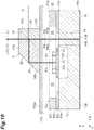
- the base 21, the movable unit 22b of the movable mirror 22, and the drive unit 23 are constituted by a silicon on insulator (SOI) substrate (semiconductor substrate) 100. That is, the mirror device 20 is constituted by the SOI substrate 100.
- the mirror device 20 is formed in a rectangular plate shape.
- the SOI substrate 100 includes a support layer 101, a device layer 102, and an intermediate layer 103.
- the support layer 101 is a first silicon layer (a first semiconductor layer).
- the device layer 102 is a second silicon layer (a second semiconductor layer).
- the intermediate layer 103 is an insulating layer that is disposed between the support layer 101 and the device layer 102.
- the SOI substrate 100 includes the support layer 101, the intermediate layer 103, and the device layer 102 in this order from the one side in the Z-axis direction.
- the base 21 is constituted by a part of the support layer 101, the device layer 102, and the intermediate layer 103.
- the first surface 21a of the base 21 is a surface of the support layer 101 which is opposite to the intermediate layer 103.
- the second surface 21b of the base 21 is a surface of the device layer 102 which is opposite to the intermediate layer 103.
- the support layer 101 that constitutes the base 21 is thicker than the device layer 102 that constitutes the base 21.
- the thickness of the support layer 101 that constitutes the base 21 is approximately four times the thickness of the device layer 102 that constitutes the base 21.
- the second surface 21b of the base 21 and a third surface 13a of the optical function member 13 are jointed to each other (refer to FIG. 3 and FIG. 4 ).
- the movable mirror 22 is disposed in a state in which an intersection between an axial line R1 and an axial line R2 is set as the central position (gravity center position).
- the axial line R1 is a straight line that extends in the X-axis direction.
- the axial line R2 is a straight line that extends in a Y-axis direction (a second direction that is perpendicular to the first direction and the third direction).
- a portion other than a portion that overlaps a sixth surface 21d of the base 21 to be described later has a shape that is linearly symmetric to each of the axial line R1 and the axial line R2.
- the movable mirror 22 (movable unit 22b) includes an arrangement portion 221, a frame portion 222, a pair of connection portions 223, and a beam portion 224.
- the arrangement portion 221, the frame portion 222, and the pair of connection portions 223 are constituted by a part of the device layer 102.
- the arrangement portion 221 has a circular shape when viewed from the Z-axis direction.
- the arrangement portion 221 includes a central portion 221a and an edge portion 221b.
- the mirror surface 22a is provided on a surface 221as of the central portion 221a on the one side in the Z-axis direction by forming a metal film (metal layer) thereon.
- the mirror surface 22a extends perpendicular to the Z-axis direction, and has a circular shape.
- the surface 221as of the central portion 221a is a surface on the intermediate layer 103 side in the device layer 102.
- the mirror surface 22a is located on the other side in the Z-axis direction in comparison to the first surface 21a of the base 21.
- the first surface 21a is located on the one side in the Z-axis direction in comparison to the mirror surface 22a.
- the edge portion 221b surrounds the central portion 221a when viewed from the Z-axis direction.
- the frame portion 222 extends in an annular shape to surround the arrangement portion 221 with a predetermined gap from the arrangement portion 221 when viewed from the Z-axis direction.
- the frame portion 222 has a circular ring shape when viewed from the Z-axis direction.
- Each of the pair of connection portions 223 connects the arrangement portion 221 and the frame portion 222 to each other.
- the pair of connection portions 223 are respectively disposed on both sides of the arrangement portion 221 in the Y-axis direction.
- the beam portion 224 is constituted by the support layer 101 and the intermediate layer 103 which are disposed on the device layer 102.
- the beam portion 224 includes an inner beam portion 224a, an outer beam portion 224b, and a pair of connection beam portions 224c.
- the inner beam portion 224a is disposed on a surface of the edge portion 221b on the one side in the Z-axis direction.
- the inner beam portion 224a surrounds the mirror surface 22a when viewed from the Z-axis direction.
- an outer edge of the inner beam portion 224a extends along an outer edge of the arrangement portion 221 with a predetermined gap from the outer edge of the arrangement portion 221 when viewed from the Z-axis direction.
- An inner edge of the inner beam portion 224a extends along an outer edge of the mirror surface 22a with a predetermined gap from the outer edge of the mirror surface 22a when viewed from the Z-axis direction.
- An end surface 224as of the inner beam portion 224a on the one side in the Z-axis direction is located on the one side in the Z-axis direction in comparison to the mirror surface 22a.
- the outer beam portion 224b is disposed on a surface of the frame portion 222 on the one side in the Z-axis direction.
- the outer beam portion 224b surrounds the inner beam portion 224a and the mirror surface 22a when viewed from the Z-axis direction.
- an outer edge of the outer beam portion 224b extends along an outer edge of the frame portion 222 with a predetermined gap from the outer edge of the frame portion 222 when viewed from the Z-axis direction.
- An inner edge of the outer beam portion 224b extends along an inner edge of the frame portion 222 with a predetermined gap from the inner edge of the frame portion 222 when viewed from the Z-axis direction.
- An end surface 224bs of the outer beam portion 224b on the one side in the Z-axis direction is located on the one side in the Z-axis direction in comparison to the mirror surface 22a.
- connection beam portions 224c are respectively disposed on surfaces of the pair of connection portions 223 on the one side in the Z-axis direction.
- the connection beam portions 224c connect the inner beam portion 224a and the outer beam portion 224b to each other.
- End surfaces 224cs of the connection beam portions 224c on the one side in the Z-axis direction are located on the one side in the Z-axis direction in comparison to the mirror surface 22a.
- the thickness of the inner beam portion 224a, the thickness of the outer beam portion 224b, and the thickness of the respective connection beam portions 224c in the Z-axis direction are the same as each other. That is, the thickness of the support layer 101 that constitutes the inner beam portion 224a, the outer beam portion 224b, and the respective connection beam portions 224c is the same in each case.
- the end surface 224as of the inner beam portion 224a, the end surface 224bs of the outer beam portion 224b, and the end surfaces 224cs of the respective connection beam portions 224c are located on the same plane perpendicular to the Z-axis direction.
- the support layer 101 that constitutes the inner beam portion 224a, the outer beam portion 224b, and the respective connection beam portions 224c is thinner than the support layer 101 that constitutes the base 21. Accordingly, the end surfaces 224as, 224bs, and 224cs are located on the one side in the Z-axis direction in comparison to the first surface 21 a of the base 21. In other words, the first surface 21a is located on the other side in the Z-axis direction in comparison to the end surfaces 224as, 224bs, and 224cs.
- a width of the outer beam portion 224b is wider than a width of the inner beam portion 224a.
- the width of the inner beam portion 224a when viewed from the Z-axis direction is a length of the inner beam portion 224a in a direction perpendicular to the extending direction of the inner beam portion 224a, and is a length of the inner beam portion 224a in a radial direction of the inner beam portion 224a in this embodiment.
- a width of each of the connection beam portions 224c is wider than the width of each of the inner beam portion 224a and the outer beam portion 224b.
- the width of each of the connection beam portion 224c is a length of each of the connection beam portion 224c along the extending direction of the inner beam portion 224a.
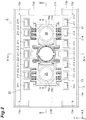
- the drive unit 23 includes a first elastic support unit 26, a second elastic support unit 27, and an actuator unit 28.
- the first elastic support unit 26, the second elastic support unit 27, and the actuator unit 28 are constituted by a part of the device layer 102.
- Each of the first elastic support unit 26 and the second elastic support unit 27 is connected between the base 21 and the movable mirror 22.
- the first elastic support unit 26 and the second elastic support unit 27 support the movable mirror 22 so that the movable mirror 22 (movable unit 22b) can move in the Z-axis direction.
- the first elastic support unit 26 includes a pair of levers 261, a first link member 262, a second link member 263, a pair of beam members 264, an intermediate member 265, a pair of first torsion bars (first torsion support portions) 266, a pair of second torsion bars (second torsion support portions) 267, a pair of non-linearity mitigation springs 268, and a plurality of electrode support portions 269.
- the pair of levers 261 are respectively disposed on both sides of the light passage opening 24 in the Y-axis direction, and face each other in the Y-axis direction.
- Each of the levers 261 has a plate shape that extends along a plane perpendicular to the Z-axis direction.
- the lever 261 includes a first portion 261a, a second portion 261b that is disposed on a side opposite to the movable mirror 22 with respect to the first portion 261a, and a third portion 261c that is connected to the first portion 261a and the second portion 261b.
- the first portion 261a and the second portion 261b extend in the X-axis direction.
- a length of the first portion 261a in the X-axis direction is shorter than a length of the second portion 261b in the X-axis direction.
- the third portions 261c of the pair of levers 261 obliquely extend to be spaced away from each other as going away from the movable mirror 22.
- the first link member 262 bridges first ends 261d of the pair of levers 261 on a side opposite to the movable mirror 22.
- the first link member 262 has a plate shape that extends along a plane perpendicular to the Z-axis direction, and extends in the Y-axis direction.
- the second link member 263 bridges second ends 261e of the pair of levers 261 on the movable mirror 22 side.
- the second link member 263 has a plate shape that extends along a plane perpendicular to the Z-axis direction, and extends in the Y-axis direction.
- a width of the second link member 263 in the X-axis direction is narrower than a width of the first link member 262 in the X-axis direction.
- a length of the second link member 263 in the Y-axis direction is shorter than a length of the first link member 262 in the Y-axis direction.
- the pair of beam members 264 respectively bridge the second portions 261b of the pair of levers 261 and the first link member 262.
- the respective beam members 264 have a plate shape that extends along a plane perpendicular to the Z-axis direction.
- the pair of beam members 264 obliquely extend to approach each other as going away from the movable mirror 22.
- the pair of levers 261, the first link member 262, the second link member 263, and the pair of beam members 264 define the light passage opening 24.
- the light passage opening 24 has a polygonal shape when viewed from the Z-axis direction.
- the light passage opening 24 is a cavity (hole).
- a material having optical transparency with respect to the measurement light L0 and the laser light L10 may be disposed in the light passage opening 24.
- the intermediate member 265 has a plate shape that extends along a plane perpendicular to the Z-axis direction, and extends in the Y-axis direction.
- the intermediate member 265 is disposed between the movable mirror 22 and the second link member 263 (in other words, between the movable mirror 22 and the light passage opening 24).
- the intermediate member 265 is connected to the movable mirror 22 through the non-linearity mitigation springs 268 as to be described later.
- the pair of first torsion bars 266 respectively bridge the first end 261d of one lever 261 and the base 21, and the first end 261d of the other lever 261 and the base 21. That is, the pair of first torsion bars 266 are respectively connected between the pair of levers 261 and the base 21.
- the first torsion bars 266 extend in the Y-axis direction.
- the pair of first torsion bars 266 are disposed on the same central line parallel to the Y-axis direction. In this embodiment, the central line of the first torsion bars 266 and the central line of the first link member 262 are located on the same straight line.
- a protrusion 261f that protrudes outward in the Y-axis direction is provided in each of the first ends 261d of the levers 261, and each of the first torsion bars 266 is connected to the protrusion 261f.
- the pair of second torsion bars 267 respectively bridge the second end 261e of one lever 261 and one end of the intermediate member 265, and the second end 261e of the other lever 261 and the other end of the intermediate member 265. That is, the pair of second torsion bars 267 are respectively connected between the pair of levers 261 and the movable mirror 22.
- the respective second torsion bars 267 extend in the Y-axis direction.
- the pair of second torsion bars 267 are disposed on the same central line parallel to the Y-axis direction.
- the pair of non-linearity mitigation springs 268 are connected between the movable mirror 22 and the intermediate member 265. That is, the pair of non-linearity mitigation springs 268 are connected between the movable mirror 22 and the second torsion bar 267.
- Each of the non-linearity mitigation springs 268 includes a meandering portion 268a that extends in a meandering manner when viewed from the Z-axis direction.
- the meandering portion 268a includes a plurality of straight portions 268b which extend in the Y-axis direction and are aligned in the X-axis direction, and a plurality of folded portions 268c which alternately connect both ends of the plurality of straight portions 268b.
- One end of the meandering portion 268a is connected to the intermediate member 265, and the other end of the meandering portion 268a is connected to the frame portion 222.
- a portion on the frame portion 222 side has a shape along the outer edge of the frame portion 222.
- the non-linearity mitigation spring 268 is constituted as follows. In a state in which the movable mirror 22 has moved in the Z-axis direction, the amount of deformation of the non-linearity mitigation spring 268 around the Y-axis direction becomes smaller than the amount of deformation of each of the first torsion bar 266 and the second torsion bar 267 around the Y-axis direction, and the amount of deformation of the non-linearity mitigation spring 268 in the X-axis direction becomes larger than the amount of deformation of each of the first torsion bar 266 and the second torsion bar 267 in the X-axis direction.
- the amount of deformation of the first torsion bar 266, the second torsion bar 267, and the non-linearity mitigation spring 268 around the Y-axis direction represents, for example, an absolute value of a twist amount (twist angle).
- the amount of deformation of the first torsion bar 266, the second torsion bar 267, and the non-linearity mitigation spring 268 in the X-axis direction represents, for example, an absolute value of a deflection amount.
- the amount of deformation of a member around the Y-axis direction represents the amount of deformation of the member in a peripheral direction of a circle of which the center is set to an axial line that passes through the center of the member and is parallel to the Y-axis. This is also true of first torsion bars 276, second torsion bars 277, and a non-linearity mitigation spring 278 to be described later.
- the plurality of electrode support portions 269 include a pair of first electrode support portions 269a, a pair of second electrode support portions 269b, and a pair of third electrode support portions 269c.
- Each of the electrode support portions 269a, 269b, and 269c has a plate shape that extends along a plane perpendicular to the Z-axis direction, and extends in the Y-axis direction.
- Each of the electrode support portions 269a, 269b, and 269c extends from the second portion 261b of the lever 261 toward a side opposite to the light passage opening 24.
- the pair of first electrode support portions 269a are disposed on the same central line parallel to the Y-axis direction.
- the pair of second electrode support portions 269b are disposed on the same central line parallel to the Y-axis direction.
- the pair of third electrode support portions 269c are disposed on the same central line parallel to the Y-axis direction. In the X-axis direction, the first electrode support portions 269a, the second electrode support portions 269b, and the third electrode support portions 269c are aligned in this order from the movable mirror 22 side.
- the second elastic support unit 27 includes a pair of levers 271, a first link member 272, a second link member 273, a pair of beam members 274, an intermediate member 275, a pair of first torsion bars (first torsion support portions) 276, a pair of second torsion bars (second torsion support portions) 277, a pair of non-linearity mitigation springs 278, and a plurality of electrode support portions 279.
- the pair of levers 271 are respectively disposed on both sides of the light passage opening 25 in the Y-axis direction, and face each other in the Y-axis direction.
- Each of the levers 271 has a plate shape that extends along a plane perpendicular to the Z-axis direction.
- the lever 271 includes a first portion 271a, a second portion 271b that is disposed on a side opposite to the movable mirror 22 with respect to the first portion 271a, and a third portion 271c that is connected to the first portion 271a and the second portion 271b.
- the first portion 271a and the second portion 271b extend in the X-axis direction.
- a length of the first portion 271a in the X-axis direction is shorter than a length of the second portion 271b in the X-axis direction.
- the third portions 271c of the pair of levers 271 obliquely extend to be spaced away from each other as going away from the movable mirror 22.
- the first link member 272 bridges first ends 271d of the pair of levers 271 on a side opposite to the movable mirror 22.
- the first link member 272 has a plate shape that extends along a plane perpendicular to the Z-axis direction, and extends in the Y-axis direction.
- the second link member 273 bridges second ends 271e of the pair of levers 271 on the movable mirror 22 side.
- the second link member 273 has a plate shape that extends along a plane perpendicular to the Z-axis direction, and extends in the Y-axis direction.
- a width of the second link member 273 in the X-axis direction is narrower than a width of the first link member 272 in the X-axis direction.
- a length of the second link member 273 in the Y-axis direction is shorter than a length of the first link member 272 in the Y-axis direction.
- the pair of beam members 274 respectively bridge the second portions 271b of the pair of levers 271 and the first link member 272.
- the respective beam members 274 have a plate shape that extends along a plane perpendicular to the Z-axis direction.
- the pair of beam members 274 obliquely extend to approach each other as going away from the movable mirror 22.
- the pair of levers 271, the first link member 272, the second link member 273, and the pair of beam members 274 define the light passage opening 25.
- the light passage opening 25 has a polygonal shape when viewed from the Z-axis direction.
- the light passage opening 25 is a cavity (hole).
- a material having optical transparency with respect to the measurement light L0 and the laser light L10 may be disposed in the light passage opening 25.
- the intermediate member 275 has a plate shape that extends along a plane perpendicular to the Z-axis direction, and extends in the Y-axis direction.
- the intermediate member 275 is disposed between the movable mirror 22 and the second link member 273 (in other words, between the movable mirror 22 and the light passage opening 25).
- the intermediate member 275 is connected to the movable mirror 22 through the non-linearity mitigation springs 278 as to be described later.
- the pair of first torsion bars 276 respectively bridge the first end 271d of one lever 271 and the base 21, and the first end 271d of the other lever 271 and the base 21. That is, the pair of first torsion bars 276 are respectively connected between the pair of levers 271 and the base 21.
- the first torsion bars 276 extend in the Y-axis direction.
- the pair of first torsion bars 276 are disposed on the same central line parallel to the Y-axis direction. In this embodiment, the central line of the first torsion bars 276 and the central line of the first link member 272 are located on the same straight line.
- a protrusion 271f that protrudes outward in the Y-axis direction is provided in each of the first ends 271d of the levers 271, and each of the first torsion bars 276 is connected to the protrusion 271f.
- the pair of second torsion bars 277 respectively bridge the second end 271e of one lever 271 and one end of the intermediate member 275, and the second end 271e of the other lever 271 and the other end of the intermediate member 275. That is, the pair of second torsion bars 277 are respectively connected between the pair of levers 271 and the movable mirror 22.
- the respective second torsion bars 277 extend in the Y-axis direction.
- the pair of second torsion bars 277 are disposed on the same central line parallel to the Y-axis direction.
- the pair of non-linearity mitigation springs 278 are connected between the movable mirror 22 and the intermediate member 275. That is, the pair of non-linearity mitigation springs 278 are connected between the movable mirror 22 and the second torsion bar 277.
- Each of the non-linearity mitigation springs 278 includes a meandering portion 278a that extends in a meandering manner when viewed from the Z-axis direction.
- the meandering portion 278a includes a plurality of straight portions 278b which extend in the Y-axis direction and are aligned in the X-axis direction, and a plurality of folded portions 278c which alternately connect both ends of the plurality of straight portions 278b.
- One end of the meandering portion 278a is connected to the intermediate member 275, and the other end of the meandering portion 278a is connected to the frame portion 222.
- a portion on the frame portion 222 side has a shape along the outer edge of the frame portion 222.
- the non-linearity mitigation spring 278 is constituted as follows. In a state in which the movable mirror 22 has moved in the Z-axis direction, the amount of deformation of the non-linearity mitigation spring 278 around the Y-axis direction becomes smaller than the amount of deformation of each of the first torsion bar 276 and the second torsion bar 277 around the Y-axis direction, and the amount of deformation of the non-linearity mitigation spring 278 in the X-axis direction becomes larger than the amount of deformation of each of the first torsion bar 276 and the second torsion bar 277 in the X-axis direction.
- the plurality of electrode support portions 279 includes a pair of first electrode support portions 279a, a pair of second electrode support portions 279b, and a pair of third electrode support portions 279c.
- Each of the electrode support portions 279a, 279b, and 279c has a plate shape that extends along a plane perpendicular to the Z-axis direction, and extends in the Y-axis direction.
- Each of the electrode support portions 279a, 279b, and 279c extends from the second portion 271b of the lever 271 toward a side opposite to the light passage opening 25.
- the pair of first electrode support portions 279a are disposed on the same central line parallel to the Y-axis direction.
- the pair of second electrode support portions 279b are disposed on the same central line parallel to the Y-axis direction.
- the pair of third electrode support portions 279c are disposed on the same central line parallel to the Y-axis direction. In the X-axis direction, the first electrode support portions 279a, the second electrode support portions 279b, and the third electrode support portions 279c are aligned in this order from the movable mirror 22 side.
- the actuator unit 28 moves the movable mirror 22 in the Z-axis direction.
- the actuator unit 28 includes a fixed comb-tooth electrode 281, a movable comb-tooth electrode 282, a fixed comb-tooth electrode 283, and a movable comb-tooth electrode 284. Positions of the fixed comb-tooth electrodes 281 and 283 are fixed.
- the movable comb-tooth electrodes 282 and 284 move in accordance with movement of the movable mirror 22.
- the fixed comb-tooth electrode 281 is provided on a part of a surface, which faces the electrode support portions 269, of the device layer 102 of the base 21.
- the fixed comb-tooth electrode 281 includes a plurality of fixed comb-teeth 281a which extend along a plane perpendicular to the Y-axis direction.
- the fixed comb-teeth 281a are aligned in the Y-axis direction with a predetermined gap therebetween.
- the movable comb-tooth electrode 282 is provided on a surface of each of the first electrode support portions 269a on the movable mirror 22 side, on surfaces of each of the second electrode support portions 269b on both sides in the X-axis direction, and on a surface of each of the third electrode support portion 269c on the movable mirror 22 side.
- the movable comb-tooth electrode 282 includes a plurality of movable comb-teeth 282a which extend along a plane perpendicular to the Y-axis direction.
- the movable comb-teeth 282a are aligned in the Y-axis direction with a predetermined gap therebetween.
- the plurality of fixed comb-teeth 281a and the plurality of movable comb-teeth 282a are alternately arranged. That is, each of the fixed comb-teeth 281a of the fixed comb-tooth electrode 281 is located between the movable comb-teeth 282a of the movable comb-tooth electrode 282.
- a distance between the fixed comb-tooth 281a and the movable comb-tooth 282a, which are adjacent to each other, is approximately several ⁇ m.
- the fixed comb-tooth electrode 283 is provided on a part of a surface, which faces the electrode support portions 279, of the device layer 102 of the base 21.
- the fixed comb-tooth electrode 283 includes a plurality of fixed comb-teeth 283a which extend along a plane perpendicular to the Y-axis direction.
- the fixed comb-teeth 283a are aligned in the Y-axis direction with a predetermined gap therebetween.
- the movable comb-tooth electrode 284 is provided on a surface of each of the first electrode support portion 279a on the movable mirror 22 side, on surfaces of each of the second electrode support portions 279b on both sides in the X-axis direction, and on a surface of each of the third electrode support portion 279c on the movable mirror 22 side.
- the movable comb-tooth electrode 284 includes a plurality of movable comb-teeth 284a which extend along a plane perpendicular to the Y-axis direction.
- the movable comb-teeth 284a are aligned in the Y-axis direction with a predetermined gap therebetween.
- each of the fixed comb-teeth 283a of the fixed comb-tooth electrode 283 is located between the movable comb-teeth 284a of the movable comb-tooth electrode 284.
- the fixed comb-teeth 283a and the movable comb-teeth 284a, which are adjacent to each other, face each other in the Y-axis direction.
- a distance between the fixed comb-tooth 283a and the movable comb-tooth 284a, which are adjacent to each other is approximately several ⁇ m.
- a plurality of electrode pads 211 are provided in the base 21.
- the electrode pads 211 are disposed on a surface of the device layer 102 in an opening 213 formed in the first surface 21a of the base 21 to reach the device layer 102.
- Some of the plurality of electrode pads 211 are electrically connected to the fixed comb-tooth electrode 281 or the fixed comb-tooth electrode 283 via the device layer 102.
- Several other electrode pads 211 among the plurality of electrode pads 211 are electrically connected to the movable comb-tooth electrode 282 or the movable comb-tooth electrode 284 via the first elastic support unit 26 or the second elastic support unit 27.
- a pair of electrode pads 212 which can be used as ground electrodes are provided in the base 21.
- the pair of electrode pads 212 are disposed on the first surface 21a to be located on both sides of the movable mirror 22 in the Y-axis direction.
- an electric signal for moving the movable mirror 22 in the Z-axis direction is input to the drive unit 23 through a lead pin 113 to be described later and a wire (not illustrated). Accordingly, for example, an electrostatic force is generated between the fixed comb-tooth electrode 281 and the movable comb-tooth electrode 282 which face each other, and the fixed comb-tooth electrode 283 and the movable comb-tooth electrode 284 which face each other so that the movable mirror 22 moves to one side in the Z-axis direction.
- the first torsion bars 266 and 276 and the second torsion bars 267 and 277 in the first elastic support unit 26 and the second elastic support unit 27 are twisted, and an elastic force is generated in the first elastic support unit 26 and the second elastic support unit 27.
- the drive unit 23 functions as an electrostatic actuator.
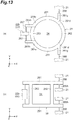
- first elastic support unit 26 and the second elastic support unit 27 will be further described with reference to FIG. 6 .
- a position at which the lever 261 and the first torsion bar 266 are connected is set as a connection position A1
- a position at which the lever 261 and the second torsion bar 267 are connected is set as a connection position A2.
- a position at which the lever 261 and the first link member 262 are connected is set as a connection position B1
- a position at which the lever 261 and the second link member 263 are connected is set as a connection position B2.
- a position at which the frame portion 222 and the second torsion bar 267 are connected is set as a connection position C1.
- connection position A1 corresponds to the central portion of a connection portion between the lever 261 and the first torsion bar 266, and is a position of an intersection between the central line of the second portion 261b of the lever 261 and the central line of the first torsion bar 266 in this embodiment.
- connection position A2 corresponds to the central portion of a connection portion between the lever 261 and the second torsion bar 267, and is a position of an intersection between the central line of the first portion 261a of the lever 261 and the central line of the second torsion bar 267 in this embodiment.
- connection position B1 corresponds to the central portion of a connection portion between the lever 261 and the first link member 262, and is a position of an intersection between the central line of the second portion 261b of the lever 261 and the central line of the first link member 262 in this embodiment.
- connection position B1 matches the connection position A1.
- connection position B2 corresponds to the central portion of a connection portion between the lever 261 and the second link member 263, and is a position of an intersection between the central line of the first portion 261a of the lever 261 and the central line of the second link member 263.
- connection position C1 corresponds to the central portion of a connection portion at which the frame portion 222 and the second torsion bar 267 are connected.
- the connection position C1 is a position at which the frame portion 222 and the other element are connected to each other.
- the connection position C1 is a position of an intersection between an outer edge (line segment that virtually extends from the outer edge) of the frame portion 222 and the central line of each of the straight portions 268b which are continuous with the frame portion 222.
- the connection position C1 is a connection position between the movable unit 22b and the second torsion bar 267.
- each of the connection position A1 and the connection position B1 is located on a side opposite to the movable mirror 22 with respect to the center T1 of the light passage opening 24 in the X-axis direction.
- Each of the connection position A2 and the connection position B2 is located on the movable mirror 22 side with respect to the center T1 of the light passage opening 24 in the X-axis direction.
- a maximum width W1 of the light passage opening 24 in the Y-axis direction is defined by a gap between the pair of levers 261 in the Y-axis direction.
- the maximum width W1 is a gap between the second portions 261b of the pair of levers 261, and is the same as a length of the first link member 262.
- the maximum width W1 is greater than a distance D1 between the connection positions C1 in the Y-axis direction.
- a distance D2 from the connection position B1 to the connection position A2 in the X-axis direction is longer than a distance D3 from the connection position B1 to the connection position A1 in the X-axis direction.
- the connection position A1 and the connection position B1 match each other, and thus the distance D3 is a value of zero.
- the first link member 262 is connected to the respective levers 261 at a position closer to the first torsion bar 266 in comparison to the second torsion bar 267.
- a distance D4 from the connection position B2 to the connection position A1 in the X-axis direction is longer than a distance D5 from the connection position B2 to the connection position A2 in the X-axis direction.
- the second link member 263 is connected to the respective levers 261 at a position closer to the second torsion bar 267 in relation to the first torsion bar 266.
- an area of the light passage opening 24 is 50% or greater of an area of the mirror surface 22a. More preferably, the area of the light passage opening 24 is 70% or greater than the area of the mirror surface 22a. In this embodiment, when viewed from the Z-axis direction, the area of the light passage opening 24 is greater than the area of the mirror surface 22a.
- a shape of the light passage opening 24 is linearly symmetric to a straight line (in this embodiment, the axial line R1) that passes through the center of the mirror surface 22a and the center T1 of the light passage opening 24.
- the first torsion bars 266 and the second torsion bars 267 do not define the light passage opening 24.
- first torsion bars 266 and the second torsion bars 267 are disposed outside of the light passage opening 24.
- a maximum width of the light passage opening 24 in the X-axis direction is wider than a maximum width of the mirror surface 22a in the X-axis direction.
- the maximum width W1 of the light passage opening 24 in the Y-axis direction is wider than the maximum width of the mirror surface 22a in the Y-axis direction.
- a position at which the lever 271 and the first torsion bar 276 are connected is set as a connection position A3, and a position at which the lever 271 and the second torsion bar 277 are connected is set as a connection position A4.
- a position at which the lever 271 and the first link member 272 are connected is set as a connection position B3, and a position at which the lever 271 and the second link member 273 are connected is set as a connection position B4.
- a position at which the frame portion 222 and the second torsion bar 277 are connected is set as a connection position C2.
- connection position A3 corresponds to the central portion of a connection portion between the lever 271 and the first torsion bar 276, and is a position of an intersection between the central line of the second portion 271b of the lever 271 and the central line of the first torsion bar 276 in this embodiment.
- connection position A4 corresponds to the central portion of a connection portion between the lever 271 and the second torsion bar 277, and is a position of an intersection between the central line of the first portion 271a of the lever 271 and the central line of the second torsion bar 277 in this embodiment.
- connection position B3 corresponds to the central portion of a connection portion between the lever 271 and the first link member 272, and is a position of an intersection between the central line of the second portion 271b of the lever 271 and the central line of the first link member 272 in this embodiment.
- connection position B3 matches the connection position A3.
- connection position B4 corresponds to the central portion of a connection portion between the lever 271 and the second link member 273, and is a position of an intersection between the central line of the first portion 271a of the lever 271 and the central line of the second link member 273 in this embodiment.
- connection position C2 corresponds to the central portion of a connection portion at which the frame portion 222 and the second torsion bar 277 are connected.
- the connection position C2 is a position at which the frame portion 222 and the other element are connected to each other.
- the connection position C2 is a position of an intersection between an outer edge (line segment that virtually extends from the outer edge) of the frame portion 222 and the central line of each of the straight portions 278b which are continuous with the frame portion 222.
- the connection position C2 is a connection position between the movable unit 22b and the second torsion bar 277.
- each of the connection position A3 and the connection position B3 is located on a side opposite to the movable mirror 22 with respect to the center T2 of the light passage opening 24 in the X-axis direction.
- Each of the connection position A4 and the connection position B4 is located on the movable mirror 22 side with respect to the center T2 of the light passage opening 24 in the X-axis direction.
- a maximum width W2 of the light passage opening 25 in the Y-axis direction is defined by a gap between the pair of levers 271 in the Y-axis direction.
- the maximum width W2 is a gap between the second portions 271b of the pair of levers 271, and is the same as a length of the first link member 272.
- the maximum width W2 is greater than a distance D6 between the connection positions C2 in the Y-axis direction.
- a distance D7 from the connection position B3 to the connection position A4 in the X-axis direction is longer than a distance D8 from the connection position B3 to the connection position A3 in the X-axis direction.
- the connection position A3 and the connection position B3 match each other, and thus the distance D8 is a value of zero.
- the first link member 272 is connected to the respective levers 271 at a position closer to the first torsion bar 276 in comparison to the second torsion bar 277.
- a distance D9 from the connection position B4 to the connection position A3 in the X-axis direction is longer than a distance D10 from the connection position B4 to the connection position A4 in the X-axis direction.
- the second link member 273 is connected to the respective levers 271 at a position closer to the second torsion bar 277 in relation to the first torsion bar 276.
- an area of the light passage opening 25 is 50% or greater of the area of the mirror surface 22a. More preferably, the area of the light passage opening 25 is 70% or greater than the area of the mirror surface 22a. In this embodiment, when viewed from the Z-axis direction, the area of the light passage opening 25 is greater than the area of the mirror surface 22a.
- a shape of the light passage opening 25 is linearly symmetric to a straight line (in this embodiment, the axial line R1) that passes through the center of the mirror surface 22a and the center T2 of the light passage opening 25.
- the first torsion bars 276 and the second torsion bars 277 do not define the light passage opening 25.
- first torsion bars 276 and the second torsion bars 277 are disposed outside of the light passage opening 25.
- a maximum width of the light passage opening 25 in the X-axis direction is wider than a maximum width of the mirror surface 22a in the X-axis direction.
- the maximum width W2 of the light passage opening 25 in the Y-axis direction is wider than the maximum width of the mirror surface 22a in the Y-axis direction.
- the optical function member 13 includes the third surface 13a (a surface on the one side in the Z-axis direction) that faces the second surface 21b of the base 21, and a fourth surface 13b opposite to the third surface 13a.
- the optical function member 13 is disposed on the other side in the Z-axis direction with respect to the mirror device 20.
- an outer edge 13c of the optical function member 13 is located outside of an outer edge 21c of the base 21. That is, when viewed from the Z-axis direction, the outer edge 13c of the optical function member 13 surrounds the outer edge 21c of the base 21.
- the optical function member 13 is integrally formed by a material having transparency with respect to the measurement light L0 and the laser light L10.
- the optical function member 13 is formed in a rectangular plate shape by glass, and has a size of approximately 15 mm ⁇ 20 mm ⁇ 4 mm (thickness).
- the material of the optical function member 13 is selected in accordance with a sensitivity wavelength of the optical module 1.
- the material is set to glass in a case where the sensitivity wavelength of the optical module 1 is a near infrared region, and the material is set to silicon in a case where the sensitivity wavelength of the optical module 1 is an intermediate infrared region.
- a pair of light transmitting portions 14 and 15 are provided in the optical function member 13.
- the light transmitting portion 14 is a portion, which faces the light passage opening 24 of the mirror device 20 in the Z-axis direction, in the optical function member 13.
- the light transmitting portion 15 is a portion, which faces the light passage opening 25 of the mirror device 20 in the Z-axis direction, in the optical function member 13.
- a surface 14a of the light transmitting portion 14 on the mirror device 20 side, and a surface 15a of the light transmitting portion 15 on the mirror device 20 side are located on the same plane as the third surface 13a.
- the light transmitting portion (second light passage portion) 14 constitutes a second portion (partial portion) of an optical path between the beam splitter unit 3 and the fixed mirror 16.
- the light transmitting portion 14 is a portion that corrects an optical path difference that occurs between an optical path between the beam splitter unit 3 and the movable mirror 22, and an optical path between the beam splitter unit 3 and the fixed mirror 16.
- the light transmitting portion 15 does not function as a light transmitting portion.
- the optical function member 13 includes a fifth surface 13d that faces the movable mirror 22 and the drive unit 23 of the mirror device 20.
- the fifth surface 13d is located on the fourth surface 13b side in comparison to the third surface 13a.
- the fifth surface 13d extends to the outer edge 13c of the optical function member 13 when viewed from the Z-axis direction.
- the fifth surface 13d extends to a pair of opposite sides which extend in the Y-axis direction in the outer edge 13c of the optical function member 13 while surrounding ends of the respective light transmitting portions 14 and 15 on the mirror device 20 side.
- the third surface 13a of the optical function member 13 is joined to the second surface 21b of the base 21 by direct bonding (for example, plasma activation bonding, surface-activated room-temperature bonding (SAB), atomic diffusion bonding (ADB), anodic bonding, fusion bonding, hydrophilic bonding, and the like).
- the third surface 13a extends to face a plurality of the electrode pads 211 and 212 provided in the base 21 on both sides of the fifth surface 13d in the Y-axis direction.
- the fifth surface 13d is located on the fourth surface 13b side in comparison to the third surface 13a, and thus the fifth surface 13d is separated from the mirror device 20 in a region where the fifth surface 13d faces the movable mirror 22 and the drive unit 23.
- the surface 14a of the light transmitting portion 14 and the surface 15a of the light transmitting portion 15 respectively face the light passage openings 24 and 25 of the mirror device 20. Accordingly, in the mirror unit 2, when the movable mirror 22 reciprocates in the Z-axis direction, the movable mirror 22 and the drive unit 23 are prevented from coming into contact with the optical function member 13.
- a sixth surface 21d which is separated from the optical function member 13 in a state in which the third surface 13a of the optical function member 13 and the second surface 21b of the base 21 are joined to each other, is provided in the base 21 of the mirror device 20.
- the sixth surface 21d is separated from the optical function member 13 in a region that includes at least a part of an outer edge of the base 21 when viewed from the Z-axis direction.
- the sixth surface 21d is formed by removing the device layer 102 and the intermediate layer 103 along one side, which extends in the Y-axis direction, in the outer edge of the base 21 by etching.
- a plurality of reference holes 13e are formed in the third surface 13a of the optical function member 13.
- the plurality of reference holes 13e are formed in the third surface 13a to correspond to a plurality of corners of the base 21.
- handling of the mirror device 20 is performed in a state in which a portion of the base 21 which corresponds to the sixth surface 21d is gripped, and thus a position of the mirror device 20 in the X-axis direction and the Y-axis direction, and an angle of the mirror device 20 in a plane perpendicular to the Z-axis direction are adjusted based on the plurality of reference holes 13e.
- the fixed mirror 16 is disposed on the other side (side opposite to the mirror device 20) in the Z-axis direction with respect to the optical function member 13, and a position of the mirror device 20 with respect to the base 21 is fixed.
- the fixed mirror 16 is formed on the fourth surface 13b of the optical function member 13 by vapor deposition.
- the fixed mirror 16 includes a mirror surface 16a perpendicular to the Z-axis direction.
- the mirror surface 22a of the movable mirror 22, and the mirror surface 16a of the fixed mirror 16 face one side (beam splitter unit 3 side) in the Z-axis direction.
- the fixed mirror 16 is formed continuously with the fourth surface 13b of the optical function member 13 to reflect light that is transmitted through the respective light transmitting portions 14 and 15 of the optical function member 13.
- a fixed mirror that reflects light transmitted through the light transmitting portion 14, and a fixed mirror that reflects light transmitted through the light transmitting portion 15 may be provided, respectively.
- the stress mitigation substrate 17 is attached to the fourth surface 13b of the optical function member 13 via the fixed mirror 16.
- the stress mitigation substrate 17 is attached to the fixed mirror 16, for example, by an adhesive.
- an outer edge of the stress mitigation substrate 17 is located outside of the outer edge 13c of the optical function member 13. That is, when viewed from the Z-axis direction, the outer edge of the stress mitigation substrate 17 surrounds the outer edge 13c of the optical function member 13.
- a thermal expansion coefficient of the stress mitigation substrate 17 is closer to a thermal expansion coefficient of the base 21 of the mirror device 20 (more specifically, a thermal expansion coefficient of the support layer 101) in comparison to a thermal expansion coefficient of the optical function member 13.
- the thickness of the stress mitigation substrate 17 is closer to the thickness of the base 21 of the mirror device 20 in comparison to the thickness of the optical function member 13.
- the stress mitigation substrate 17 is formed in a rectangular plate shape by silicon, and has a size of approximately 16 mm ⁇ 21 mm ⁇ 0.65 mm (thickness).
- the mirror unit 2 configured as described above is attached to the support 9 by fixing a surface of the stress mitigation substrate 17 on a side opposite to the optical function member 13 to a surface 9a of the support 9 (surface on the one side in the Z-axis direction), for example, by an adhesive.
- a position of the mirror device 20 in the X-axis direction and the Y-axis direction and an angle of the mirror device 20 in a plane perpendicular to the Z-axis direction are adjusted based on a reference hole 9b that is formed in the support 9.
- the second support structure 12 is not illustrated.
- the first support structure 11 includes a frame body 111, a light transmitting member 112, and a plurality of lead pins 113.
- the frame body 111 is formed so as to surround the mirror unit 2 when viewed from the Z-axis direction, and is attached to the surface 9a of the support 9, for example, by an adhesive such as silver solder.
- the frame body 111 is formed of ceramic, and has a rectangular frame shape.
- An end surface 111 a of the frame body 111 on a side opposite to the support 9 is located on a side opposite to the support 9 in comparison to the first surface 21a of the base 21 of the mirror device 20.
- the light transmitting member 112 is formed so as to close an opening of the frame body 111, and is attached to the end surface 111a of the frame body 111, for example, with an adhesive.
- the light transmitting member 112 is formed of a material having transparency with respect to the measurement light L0 and the laser light L10, and has a rectangular plate shape for example.
- the end surface 111a of the frame body 111 is located on a side opposite to the support 9 in comparison to the first surface 21a of the base 21 of the mirror device 20, and thus the light transmitting member 112 is separated from the mirror device 20.
- the support 9, the frame body 111, and the light transmitting member 112 constitute a package that accommodates the mirror unit 2.
- the respective lead pins 113 are provided in the frame body 111 in such a manner that one end 113a is located inside of the frame body 111, and the other end (not illustrated) is located outside of the frame body 111.
- the one ends 113a of the lead pins 113 are electrically connected to the electrode pads 211 and 212 corresponding to the lead pins 113 in the mirror device 20 by wires (not illustrated).
- an electric signal for moving the movable mirror 22 in the Z-axis direction is input to the drive unit 23 through the plurality of lead pins 113.
- a stepped surface 111b that extends in the X-axis direction on both sides of the optical function member 13 in the Y-axis direction is formed in the frame body 111, and one end 113a of each of the lead pins 113 is disposed on the stepped surface 111b.
- the lead pin 113 extends in the Z-axis direction on both sides of the support 9 in the Y-axis direction, and the other end of the lead pin 113 is located on the other side in the Z-axis direction in comparison to the support 9.
- the beam splitter unit 3 is attached to a surface 112a of the light transmitting member 112 on a side opposite to the mirror device 20, for example, by an optical adhesive that also functions as a refractive index matching agent.
- the beam splitter unit 3 includes a first mirror surface 31, a second mirror surface 32, and a plurality of optical planes 33a, 33b, 33c, and 33d.
- the beam splitter unit 3 is constituted by joining a plurality of optical blocks 34 and 35.
- the respective optical blocks 34 and 35 are formed of a material having a refractive index that is the same as or similar to that of the optical function member 13.
- FIG. 10 is a schematic cross-sectional view of the mirror unit 2 and the beam splitter unit 3 illustrated in FIG. 1 , and in FIG. 10 , the mirror device 20 is schematically illustrated, for example, in a state in which dimensions in the Z-axis direction are enlarged in comparison to actual dimensions.
- the first mirror surface 31 is a mirror surface (for example, a half mirror surface) that is inclined with respect to the Z-axis direction, and is formed between the optical block 34 and the optical block 35.
- the first mirror surface 31 is a surface that is parallel to the Y-axis direction, has an angle of 45° with respect to the Z-axis direction, and is inclined to be spaced away from the light incident unit 4 as it approaches the mirror device 20.
- the first mirror surface 31 has a function of reflecting a part of the measurement light L0 and allowing the remainder of the measurement light L0 to be transmitted therethrough, and a function of reflecting a part of the laser light L10 and allowing the remainder of the laser light L10 to be transmitted therethrough.
- the first mirror surface 31 is formed of a dielectric multi-layer film.
- the first mirror surface 31 overlaps the light passage opening 24 of the mirror device 20, the light transmitting portion 14 of the optical function member 13, and the mirror surface 16a of the fixed mirror 16 when viewed from the Z-axis direction, and overlaps the light incident unit 4 when viewed form the X-axis direction (refer to FIG. 1 ). That is, the first mirror surface 31 faces the fixed mirror 16 in the Z-axis direction, and faces the light incident unit 4 in the X-axis direction.
- the second mirror surface 32 is a mirror surface (for example, a total reflection mirror surface) that is parallel to the first mirror surface 31, and is formed in the optical block 35 to be located on a side opposite to the light incident unit 4 with respect to the first mirror surface 31.
- the second mirror surface 32 has a function of reflecting the measurement light L0 and a function of reflecting the laser light L10.
- the second mirror surface 32 is formed of a metal film.
- the second mirror surface 32 overlaps the mirror surface 22a of the movable mirror 22 of the mirror device 20 when viewed from the Z-axis direction, and overlaps the first mirror surface 31 when viewed from the X-axis direction. That is, the second mirror surface 32 faces the movable mirror 22 in the Z-axis direction, and faces the first mirror surface 31 in the X-axis direction.
- the optical plane 33a is a plane perpendicular to the Z-axis direction, and is formed in the optical block 35 to be located on a side opposite to the mirror device 20 with respect to the first mirror surface 31.
- the optical plane 33b is a plane perpendicular to the Z-axis direction, and is formed in the optical block 35 to be located on the mirror device 20 side with respect to the second mirror surface 32.
- the optical plane 33c is a plane perpendicular to the Z-axis direction, and is formed in the optical block 34 to be located on the mirror device 20 side with respect to the first mirror surface 31.
- the optical surface 33b and the optical surface 33c are located on the same plane.
- the optical surface 33d is a plane perpendicular to the X-axis direction, and is formed in the optical block 34 to be located on the light incident unit 4 side with respect to the first mirror surface 31.
- the respective optical surfaces 33a, 33b, 33c, and 33d have a function of allowing the measurement light L0 to be transmitted therethrough, and a function of allowing the laser light L10 to be transmitted therethrough.
- the beam splitter unit 3 configured as described above is attached to the light transmitting member 112 by fixing the optical surface 33b and the optical surface 33c which are located on the same plane to the surface 112a of the light transmitting member 112, for example, by an optical adhesive.
- a position of the beam splitter unit 3 in the X-axis direction and the Y-axis direction, and an angle of the beam splitter unit 3 in a plane perpendicular to the Z-axis direction are adjusted based on the reference hole 9b formed in the support 9.
- the second support structure 12 is not illustrated.
- the remainder of the measurement light L0 is reflected by the first mirror surface 31, and reaches the mirror surface 16a of the fixed mirror 16 through the optical surface 33c, the light transmitting member 112, the light passage opening 24 of the mirror device 20, and the light transmitting portion 14 of the optical function member 13.
- the remainder of the measurement light L0 is reflected by the mirror surface 16a of the fixed mirror 16, proceeds on the same optical path P2 in an opposite direction, and is transmitted through the first mirror surface 31.
- the part of the measurement light L0 which is reflected by the first mirror surface 31, and the remainder of the measurement light L0 which is transmitted through the first mirror surface 31 become interference light L1, and the interference light L1 of the measurement light is emitted from the beam splitter unit 3 through the optical surface 33a along the Z-axis direction.
- the laser light L10 when the laser light L10 is incident to the beam splitter unit 3 in the Z-axis direction through the optical surface 33a, a part of the laser light L10 is reflected by the first mirror surface 31 and the second mirror surface 32, and reaches the mirror surface 22a of the movable mirror 22 through the optical surface 33b and the light transmitting member 112.
- the part of the laser light L10 is reflected by the mirror surface 22a of the movable mirror 22, proceeds on the same optical path P3 in an opposite direction, and is reflected by the first mirror surface 31.
- the remainder of the laser light L10 is transmitted through the first mirror surface 31, and reaches the mirror surface 16a of the fixed mirror 16 through the optical surface 33c, the light transmitting member 112, the light passage opening 24 of the mirror device 20, and the light transmitting portion 14 of the optical function member 13.
- the remainder of the laser light L10 is reflected by the mirror surface 16a of the fixed mirror 16, proceeds on the same optical path P4 in an opposite direction, and is transmitted through the first mirror surface 31.
- the part of the laser light L10 which is reflected by the first mirror surface 31, and the remainder of the laser light L10 which is transmitted through the first mirror surface 31 become interference light L11, and the interference light L11 of the laser light is emitted from the beam splitter unit 3 through the optical surface 33a along the Z-axis direction.
- the light passage opening 24 of the mirror device 20 constitutes a first portion P2a of the optical path P2 of the measurement light L0 and a first portion P4a of the optical path P4 of the laser light L10 in an optical path between the beam splitter unit 3 and the fixed mirror 16.
- the light transmitting portion 14 of the optical function member 13 constitutes a second portion P2b of the optical path P2 of the measurement light L0 and a second portion P4b of the optical path P4 of the laser light L10 in the optical path between the beam splitter unit 3 and the fixed mirror 16.
- the second portion P2b of the optical path P2 of the measurement light L0 is constituted by the light transmitting portion 14, thus an optical path difference between both the optical paths P1 and P2 is corrected so that a difference between an optical path length (optical path length in consideration of a refractive index of respective media through which the optical path passes) of the optical path P1 of the measurement light L0, and an optical path length of the optical path P2 of the measurement light L0 decreases.
- the second portion P4b of the optical path P4 of the laser light L10 is constituted by the light transmitting portion 14, thus an optical path difference between both the optical paths P3 and P4 is corrected so that a difference between an optical path length of the optical path P3 of the laser light L10 and an optical path length of the optical path P4 of the laser light L10 decreases.
- a refractive index of the light transmitting portion 14 is the same as a refractive index of the respective optical blocks which constitute the beam splitter unit 3, and a distance between the first mirror surface 31 and the second mirror surface 32 in the X-axis direction is the same as the thickness of the light transmitting portion 14 in the Z-axis direction (that is, a distance between the surface 14a of the light transmitting portion 14 and the fourth surface 13b of the optical function member 13 in the Z-axis direction).
- the second support structure 12 includes a connection unit 120.
- the connection unit 120 includes a main body portion 121, a frame body 122, and a fixing plate 123.
- the main body portion 121 includes a pair of side wall portions 124 and 125, and a ceiling wall portion 126.
- the pair of side wall portions 124 and 125 face each other in the X-axis direction.
- An opening 124a is formed in the side wall portion 124 on one side in the X-axis direction.
- the ceiling wall portion 126 faces the support 9 in the Z-axis direction.
- An opening 126a is formed in the ceiling wall portion 126.
- the main body portion 121 is integrally formed of a metal.
- Positioning pins 121a are provided in the main body portion 121.
- the main body portion 121 is positioned with respect to the support 9 by inserting the positioning pin 121a into the reference hole 9b formed in the support 9, and is attached to the support 9 in this state, for example, by a bolt.
- the frame body 122 is disposed on a surface of the side wall portion 124 on a side opposite to the beam splitter unit 3. An opening of the frame body 122 faces the beam splitter unit 3 through the opening 124a of the side wall portion 124.
- the light incident unit 4 is disposed in the frame body 122.
- the fixing plate 123 is a member that fixes the light incident unit 4 disposed in the frame body 122 to the main body portion 121 (details will be described later).
- the second support structure 12 further includes a holding unit 130.
- the holding unit 130 includes a main body portion 131, a frame body 132 and a fixing plate 133.
- the main body portion 131 is attached to a surface of the ceiling wall portion 126 which is opposite to the support 9.
- the main body portion 131 is positioned with respect to the main body portion 121 of the connection unit 120 by a positioning pin, and is attached to the ceiling wall portion 126 in this state, for example, by a bolt.
- a concave portion 134 is formed in a surface of the main body portion 131 which is opposite to the support 9.
- a first light passage hole 135, a second light passage hole 136, and a third light passage hole 137 are formed in a bottom surface of the concave portion 134.
- the first light passage hole 135 is formed at a position that faces the first mirror surface 31 of the beam splitter unit 3 in the Z-axis direction.
- the second light passage hole 136 is formed on the other side of the first light passage hole 135 in the X-axis direction (that is, on a side opposite to the light incident unit 4).
- the third light passage hole 137 is formed on the other side of the second light passage hole 136 in the X-axis direction.
- the frame body 132 is disposed on the bottom surface of the concave portion 134. An opening of the frame body 132 faces the third light passage hole 137.
- the second light source 7 is disposed in the frame body 132.
- the first light detector 6 is disposed on the bottom surface of the concave portion 134 in a state of facing the first light passage hole 135.
- the second light detector 8 is disposed on the bottom surface of the concave portion 134 in a state of facing the second light passage hole 136.
- the fixing plate 133 is a member that fixes the first light detector 6 and the second light detector 8 which are disposed on the bottom surface of the concave portion 134, and the second light source 7 that is disposed in the frame body 132 to the main body portion 131 (details will be described later).
- the light incident unit 4 includes a holder 41 and a collimator lens 42.
- the holder 41 holds the collimator lens 42, and is configured so that an optical fiber (not illustrated) that guides the measurement light L0 can be connected to the holder 41.
- the collimator lens 42 collimates the measurement light L0 emitted from the optical fiber.
- an optical axis of the optical fiber matches an optical axis of the collimator lens 42.
- a flange portion 41a is provided in the holder 41.
- the flange portion 41a is disposed between the frame body 122 and the fixing plate 123.
- fixing plate 123 is attached to the side wall portion 124, for example, by a bolt, and the light incident unit 4 disposed in the frame body 122 is fixed to the main body portion 121.
- the light incident unit 4 is disposed on one side of the beam splitter unit 3 in the X-axis direction, and is supported by the second support structure 12.
- the light incident unit 4 allows measurement light L0 that is incident from the first light source through a measurement target or measurement light L0 that is generated from the measurement target (in this embodiment, the measurement light L0 guided by the optical fiber) to be incident to the beam splitter unit 3.
- a filter 54 is attached to the frame body 122.
- the filter 54 has a function of cutting off the laser light L10.
- the filter 54 is disposed in the opening 124a of the side wall portion 124 in a state of being inclined with respect to an optical axis of the light incident unit 4.
- the filter 54 closes the opening of the frame body 122 when viewed form the X-axis direction.
- the filter 54 is disposed between the light incident unit 4 and the beam splitter unit 3, and is supported by the second support structure 12 in a state of being inclined with respect to an optical axis of the light incident unit 4.
- an optical surface of the filter 54 is a surface that is parallel to the Z-axis direction and has an angle of 10° to 20° with respect to the Y-axis direction.
- the optical axis of the light incident unit 4 is parallel to the X-axis direction.
- the filter 54 is inclined with respect to the optical axis of the light incident unit 4, light in the same wavelength range as the laser light 110 is reflected to the outside of an interference optical system, and thus it is possible to reliably prevent the light from being stray light.
- the first light detector 6 includes a holder 61, a light detection element 62, and a condensing lens 63.
- the holder 61 holds the light detection element 62 and the condensing lens 63.
- the light detection element 62 detects the interference light L1 of the measurement light.
- the light detection element 62 is an InGaAs photodiode.
- the condensing lens 63 condenses the interference light L1 of the measurement light incident to the light detection element 62 to the light detection element 62.
- an optical axis of the light detection element 62 and an optical axis of the condensing lens 63 match each other.
- a flange portion 61a is provided in the holder 61.
- the flange portion 61a is disposed between the bottom surface of the concave portion 134 of the main body portion 131, and the fixing plate 133.
- the fixing plate 133 attached to the main body portion 131, for example, by a bolt, and thus the first light detector 6 disposed on the bottom surface of the concave portion 134 is fixed to the main body portion 131.
- the first light detector 6 is disposed on one side of the beam splitter unit 3 in the Z-axis direction, and is supported by the second support structure 12.
- the first light detector 6 faces the first mirror surface 31 of the beam splitter unit 3 in the Z-axis direction.
- the first light detector 6 detects the interference light L1 of the measurement light emitted from the beam splitter unit 3.
- the second light detector 8 includes a holder 81, a light detection element 82, and a condensing lens 83.
- the holder 81 holds the light detection element 82 and the condensing lens 83.
- the light detection element 82 detects the interference light L11 of the laser light.
- the light detection element 82 is a Si photodiode.
- the condensing lens 83 condenses the interference light L11 of the laser light incident to the light detection element 82 to the light detection element 82.
- an optical axis of the light detection element 82 and an optical axis of the condensing lens 83 match each other.
- a flange portion 81a is provided in the holder 81.
- the flange portion 81a is disposed between the bottom surface of the concave portion 134 of the main body portion 131, and the fixing plate 133.
- the fixing plate 133 attached to the main body portion 131, for example, by a bolt, and thus the second light detector 8 disposed on the bottom surface of the concave portion 134 is fixed to the main body portion 131.
- the second light detector 8 is disposed on one side of the beam splitter unit 3 in the Z-axis direction, and is supported by the second support structure 12.
- the second light detector 8 detects the interference light L11 of the laser light emitted from the beam splitter unit 3.
- the second light source 7 includes a holder 71, a light-emitting element 72, and a collimator lens 73.
- the holder 71 holds the light-emitting element 72 and the collimator lens 73.
- the light-emitting element 72 emits the laser light L10.
- the light-emitting element 72 is a semiconductor laser such as a VCSEL.
- the collimator lens 73 collimates the laser light L10 emitted from the light-emitting element 72.
- an optical axis of the light-emitting element 72 and an optical axis of the collimator lens 73 match each other.
- a flange portion 71a is provided in the holder 71.
- the flange portion 71a is disposed between the frame body 132 and the fixing plate 133.
- the fixing plate 133 is attached to the main body portion 131, for example, by a bolt, and thus the second light source 7 disposed in the frame body 132 is fixed to the main body portion 131.
- the second light source 7 is disposed on one side of the beam splitter unit 3 in the Z-axis direction, and is supported by the second support structure 12.
- the second light source 7 emits the laser light L10 that is to be incident to the beam splitter unit 3.
- the holding unit 130 holds the first light detector 6, the second light detector 8, and the second light source 7 so that the first light detector (first optical device) 6, the second light detector (second optical device) 8, and the second light source (third optical device) 7 face the same side, and the first light detector 6, the second light detector 8, and the second light source 7 are aligned in this order.
- the holding unit 130 on one side of the beam splitter unit 3 in the Z-axis direction, holds the first light detector 6, the second light detector 8, and the second light source 7 so that the first light detector 6, the second light detector 8, and the second light source 7 face the other side (that is, the beam splitter unit 3 side).
- the holding unit 130 holds the first light detector 6, the second light detector 8, and the second light source 7 so that the first light detector 6, the second light detector 8, and the second light source 7 are aligned in this order from one side (that is, the light incident unit 4 side) in the X-axis direction.
- a first mirror 51, a second mirror 52, and a third mirror 53 are attached to the main body portion 131 of the holding unit 130.
- the first mirror 51 is held by the holding unit 130 to be located on a side opposite to the first light detector 6 with respect to the first light passage hole 135.
- the second mirror 52 is held by the holding unit 130 to be located on a side opposite to the second light detector 8 with respect to the second light passage hole 136.
- the third mirror 53 is held by the holding unit 130 to be located on a side opposite to the second light source 7 with respect to the third light passage hole 137.
- the first mirror 51 is a dichroic mirror that has a function of allowing the measurement light L0 to be transmitted therethrough and of reflecting the laser light L10, and is inclined with respect to the optical axis of the first light detector 6.
- the first mirror 51 is disposed between the beam splitter unit 3 and the first light detector 6. That is, the first mirror 51 is disposed to face the beam splitter unit 3 and the first light detector 6.
- an optical surface of the first mirror 51 is a surface that is parallel to the Y-axis direction and has an angle of 45° with respect to the Z-axis direction.
- the optical axis of the first light detector 6 is parallel to the Z-axis direction.
- the second mirror 52 is a mirror (for example, a half mirror) that has a function of reflecting a part of the laser light L10 and allowing the remainder of the laser light L10 to be transmitted therethrough, and is parallel to the first mirror 51.
- the second mirror 52 is disposed to overlap the first mirror 51 when viewed from the X-axis direction, and to overlap the second light detector 8 when viewed from the Z-axis direction. That is, the second mirror 52 is disposed to face the first mirror 51 and the second light detector 8.
- an optical surface of the second mirror 52 is a surface that is parallel to the Y-axis direction, and has an angle of 45° with respect to the Z-axis direction.
- the third mirror 53 is a mirror (for example, a total reflection mirror) that has a function of reflecting the laser light L10 and is parallel to the second mirror 52.
- the third mirror 53 is disposed to overlap the second mirror 52 when viewed from the X-axis direction, and overlap the second light source 7 when viewed from the Z-axis direction. That is, the third mirror 53 is disposed to face the second mirror 52 and the second light source 7.
- an optical surface of the third mirror 53 is a surface that is parallel to the Y-axis direction, and has an angle of 45° with respect to the Z-axis direction.
- An aperture 55 is attached to the main body portion 131 of the holding unit 130.
- the aperture 55 is held by the holding unit 130 to be located between the first mirror 51 and the first light detector 6.
- the aperture 55 is a member in which an opening having a circular shape is formed when viewed from the Z-axis direction, and is disposed in the first light passage hole 135.
- the interference light L1 of the measurement light which is emitted from the beam splitter unit 3 in the Z-axis direction, is transmitted through the first mirror 51, is incident to the first light detector 6 through the aperture 55, and is detected by the first light detector 6.
- the laser light L10 emitted from the second light source 7 is reflected by the third mirror 53, is transmitted through the second mirror 52, is reflected by the first mirror 51, and is incident to the beam splitter unit 3 in the Z-axis direction.
- the interference light L11 of the laser light which is emitted from the beam splitter unit 3 in the Z-axis direction, is reflected by the first mirror 51 and the second mirror 52, is incident to the second light detector 8, and is detected by the second light detector 8.
- the first link member 262 bridges the pair of levers 261, and the light passage opening 24 is defined by the respective levers 261 and the first link member 262.
- the first link member 272 bridges the pair of levers 271, and the light passage opening 25 is defined by the respective levers 271 and the first link member 272. Accordingly, an optical path can be set to pass through the light passage opening 24 or 25, and it is possible to miniaturize the entirety of a device, for example, in comparison to a case where the optical path is set to pass through outside of the mirror device 20.
- first link member 262 bridges the pair of levers 261
- first link member 272 bridges the pair of levers 271, and thus it is possible to improve external force resistance of the first elastic support unit 26 and the second elastic support unit 27. Accordingly, for example, it is possible to suppress an influence on an operation of the movable mirror 22 or contact risk between the movable comb-teeth 282a and 284a and the fixed comb-teeth 281a and 283a due to vibration or impact from outside, and thus it is possible to stabilize the operation of the movable mirror 22. As a result, it is possible to improve control characteristics of the movable mirror 22.
- connection positions A1 between the pair of levers 261 and the pair of first torsion bars 266 are located on a side opposite to the movable unit 22b with respect to the center T1 of the light passage opening 24 in the X-axis direction, and the maximum width W1 of the light passage opening 24 in the Y-axis direction is defined by a gap between the pair of levers 261 in the Y-axis direction.
- connection positions A3 between the pair of levers 271 and the pair of first torsion bars 276 are located on a side opposite to the movable unit 22b with respect to the center T2 of the light passage opening 25 in the X-axis direction, and the maximum width W2 of the light passage opening 25 in the Y-axis direction is defined by a gap between the pair of levers 27 1 in the Y-axis direction. Accordingly, it is possible to secure the size of the light passage openings 24 and 25, and thus it is possible to secure optical performance. As a result, according to the mirror device 20, the miniaturization of the entirety of a device, the improvement of external force resistance of the first elastic support unit 26 and the second elastic support unit 27, and the securement of the optical performance are realized.
- the light passage opening 24 is defined by the pair of levers 261, the first link member 262, and the second link member 263, and the light passage opening 25 is defined by the pair of levers 271, the first link member 272, and the second link member 273. Accordingly, it is possible to further improve the external force resistance of the first elastic support unit 26 and the second elastic support unit 27.
- the pair of beam members 264 respectively bridge the pair of levers 261 and the first link member 262, and the pair of beam members 274 respectively bridge the pair of levers 271 and the first link member 272. Accordingly, it is possible to further improve the external force resistance of the first elastic support unit 26 and the second elastic support unit 27.
- Each of the first torsion bars 266 is connected to the first ends 261d of the pair of levers 261, and each of the second torsion bars 267 is connected to the second ends 261e of the pair of levers 261.
- each of the first torsion bars 276 is connected to the first ends 271d of the pair of levers 271, and each of the second torsion bars 277 is connected to the second ends 271e of the pair of levers 271. Accordingly, it is possible to secure the size of the light passage openings 24 and 25 more preferably.
- the maximum width W1 of the light passage opening 24 in the Y-axis direction is greater than the distance D1 (distance between connection positions of the movable unit 22b and the pair of second torsion bars 267) between the connection positions C1 of the frame portion 222 and the pair of second torsion bars 267 in the Y-axis direction.
- the maximum width W2 of the light passage opening 25 in the Y-axis direction is greater than the distance D6 (distance between connection positions of the movable unit 22b and the pair of second torsion bars 277) between connection positions C2 of the frame portion 222 and the pair of second torsion bars 277 in the Y-axis direction. Accordingly, it is possible to secure the size of the light passage openings 24 and 25 in the Y-axis direction more preferably.
- the distance D2 from the connection position B1 with the first link member 262 to the connection position A2 with each of the pair of second torsion bars 267 in the X-axis direction is longer than the distance D3 from the connection position B1 with the first link member 262 to the connection position A1 with each of the pair of first torsion bars 266 in the X-axis direction. Accordingly, it is possible to secure the size of the light passage opening 24 in a direction along the pair of levers 261 more preferably.
- the distance D7 from the connection position B3 with the first link member 272 to the connection position A4 with each of the pair of second torsion bars 277 in the X-axis direction is longer than the distance D8 from the connection position B3 with the first link member 272 to the connection position A3 with each of the pair of first torsion bars 276 in the X-axis direction. Accordingly, it is possible to secure the size of the light passage opening 24 in a direction along the pair of levers 271 more preferably.
- the mirror device 20 may have a configuration similar to a first modification example illustrated in FIG. 11 .
- the movable unit 22b further includes a pair of brackets 225 and a pair of brackets 226.
- the respective brackets 225 and the respective brackets 226 are formed at a part of the device layer 102.
- the respective brackets 225 extend in the Y-axis direction, and have a rectangular shape when viewed from the Z-axis direction.
- One of the brackets 225 protrudes from a lateral surface of the frame portion 222 toward one side in the Y-axis direction, and the other bracket 225 protrudes from the lateral surface of the frame portion 222 toward the other side in the Y-axis direction.
- the pair of brackets 225 are disposed on the same central line parallel to the Y-axis direction.
- the respective brackets 225 are disposed on the light passage opening 24 side with respect to the center of the mirror surface 22a.
- the respective brackets 226 extend in the Y-axis direction, and have a rectangular shape when viewed from the Z-axis direction.
- One of the brackets 226 protrudes from a lateral surface of the frame portion 222 toward one side in the Y-axis direction, and the other bracket 226 protrudes from the lateral surface of the frame portion 222 toward the other side in the Y-axis direction.
- the pair of brackets 226 are disposed on the same central line parallel to the Y-axis direction.
- the respective brackets 226 are disposed on the light passage opening 25 side with respect to the center of the mirror surface 22a.
- the first elastic support unit 26 does not include the pair of beam members 264, the intermediate member 265, and the pair of non-linearity mitigation springs 268. Both ends of the second link member 263 extend in the Y-axis direction. An intermediate portion of the second link member 263 extends along the frame portion 222, and is curved in a convex shape toward a side opposite to the movable mirror 22.
- the pair of second torsion bars 267 are respectively connected to tip ends of the pair of brackets 225. That is, the pair of second torsion bars 267 are respectively connected between the pair of levers 261 and the movable mirror 22.
- the electrode support portion 269 includes only the pair of second electrode support portions 269b.
- the second elastic support unit 27 does not include the pair of beam members 274, the intermediate member 275, and the pair of non-linearity mitigation springs 278. Both ends of the second link member 273 extend in the Y-axis direction. An intermediate portion of the second link member 273 extends along the frame portion 222, and is curved in a convex shape toward a side opposite to the movable mirror 22.
- the pair of second torsion bars 277 are respectively connected to tip ends of the pair of brackets 226. That is, the pair of second torsion bars 277 are respectively connected between the pair of levers 271 and the movable mirror 22.
- the electrode support portion 279 includes only the pair of second electrode support portions 279b.
- the actuator unit 28 further includes a fixed comb-tooth electrode 285 and a movable comb-tooth electrode 286.
- the fixed comb-tooth electrode 285 is disposed along an outer edge of the movable mirror 22 (along the frame portion 222).
- the fixed comb-tooth electrode 285 is provided on a surface of the device layer 102 of the base 21 which faces an outer surface of the frame portion 222 in the Y-axis direction.
- the fixed comb-tooth electrode 285 includes a plurality of fixed comb-teeth 285a which extend along a plane perpendicular to the X-axis direction.
- the fixed comb-teeth 285a are aligned in the X-axis direction with a predetermined gap.
- the movable comb-tooth electrode 286 is disposed along an outer edge of the movable mirror 22 (along the frame portion 222).
- the movable comb-tooth electrode 286 is provided on outer surface of the frame portion 222 in the Y-axis direction. That is, the frame portion 222 constitutes an electrode support portion that supports the movable comb-tooth electrode 286.
- the movable comb-tooth electrode 286 includes a plurality of movable comb-teeth 286a which extend along a plane perpendicular to the X-axis direction.
- the movable comb-teeth 286a are aligned in the X-axis direction with a predetermined gap.
- each of the fixed comb-teeth 285a of the fixed comb-tooth electrode 285 is located between the movable comb-teeth 286a of the movable comb-tooth electrode 286.
- a distance between the fixed comb-tooth 285a and the movable comb-tooth 286a which are adjacent to each other is approximately several ⁇ m.
- connection positions C1 between the frame portion 222 and the second torsion bars 267, and connection positions C3 between the movable unit 22b and the second torsion bars 267 are illustrated.
- the connection position C1 is a position at which the frame portion 222 and the other element are connected to each other.
- the connection position C3 is a position at which the bracket 225 and the second torsion bar 267 are connected to each other.
- the maximum width W1 of the light passage opening 24 in the Y-axis direction is greater than a distance D1 between the connection positions C1 in the Y-axis direction. In addition, the maximum width W1 is greater than a distance D11 between the connection positions C3 in the Y-axis direction.
- connection positions C2 between the frame portion 222 and the second torsion bars 277, and connection positions C4 between the movable unit 22b and the second torsion bars 277 are illustrated.
- the connection position C2 is a position at which the frame portion 222 and the other element are connected to each other.
- the connection position C4 is a position at which the bracket 225 and the second torsion bar 277 are connected to each other.
- the maximum width W2 of the light passage opening 25 in the Y-axis direction is greater than the distance D6 between the connection positions C2 in the Y-axis direction. In addition, the maximum width W2 is greater than a distance D12 between the connection positions C4 in the Y-axis direction.
- the miniaturization of the entirety of a device, the improvement of the external force resistance of the first elastic support unit 26 and the second elastic support unit 27, and the securement of the optical performance are also realized in a similar manner as in the above-described embodiment.
- the mirror device 20 may have a configuration similar to a second modification example illustrated in FIG. 12 .
- the first elastic support unit 26 further includes a pair of beam members 264A.
- the pair of beam members 264A respectively bridge the third portions 261c of the pair of levers 261 and the second link member 263.
- the respective beam members 264A have a plate shape that extends along a plane perpendicular to the Z-axis direction.
- the pair of beam members 264A obliquely extend to be spaced away from each other as going away from the movable mirror 22.
- the pair of beam members 264A define the light passage opening 24 in combination with the pair of levers 261, the first link member 262, the second link member 263, and the pair of beam members 264.
- the second elastic support unit 27 further includes a pair of beam members 274A.
- the pair of beam members 274A respectively bridge third portions 271c of the pair of levers 271 and the second link member 273.
- the respective beam members 274A have a plate shape that extends along a plane perpendicular to the Z-axis direction.
- the pair of beam members 274A obliquely extend to be spaced away from each other as going away from the movable mirror 22.
- the pair of beam members 274A define the light passage opening 25 in combination with the pair of levers 271, the first link member 272, the second link member 273, and the pair of beam members 274.
- the miniaturization of the entirety of a device, the improvement of the external force resistance of the first elastic support unit 26 and the second elastic support unit 27, and the securement of the optical performance are also realized in a similar manner as in the above-described embodiment.
- the first elastic support unit 26 and the second elastic support unit 27 include the beam member 264A and the beam member 274A, respectively, it is possible to further improve the external force resistance of the first elastic support unit 26 and the second elastic support unit 27.
- the first elastic support unit 26 may have a configuration similar to a third modification example illustrated in FIG. 13(a) .
- the first elastic support unit 26 does not include the pair of beam members 264 and the pair of non-linearity mitigation springs 268.
- the electrode support portion 269 is not illustrated.
- the pair of levers 261, the first link member 262, and the second link member 263 have a circular ring shape as a whole when viewed from the Z-axis direction. That is, each of the pair of levers 261, the first link member 262, and the second link member 263 extends in a state of being curved to form a circular arc shape.
- a boundary between the pair of levers 261, the first link member 262, and the second link member 263 is indicated by two-dot chain line.
- the light passage opening 24 has a circular shape when viewed from the Z-axis direction.
- a bracket 261g is provided in the first end 261d of each of the levers 261, and the lever 261 is connected to each of the first torsion bars 266 at the bracket 261g.
- a bracket 261h is provided in the second end 261e of each of the levers 261, and the lever 261 is connected to each of the second torsion bars 267 at the bracket 261h.
- the second elastic support unit 27 is omitted, but in the third modification example, the second elastic support unit 27 may also be configured in a similar manner as in the first elastic support unit 26.
- the miniaturization of the entirety of a device, the improvement of the external force resistance of the first elastic support unit 26 and the second elastic support unit 27, and the securement of the optical performance are also realized in a similar manner as in the above-described embodiment. That is, as illustrated in FIG. 13(a) , the pair of levers 261 may face each other in the Y-axis direction, and each of the levers 261 may include at least a portion (component) that extends in the X-axis direction.
- the first link member 262 and the second link member 263 may bridge the pair of levers 261, and may include at least a portion (component) that extends along the Y-axis direction.
- the first elastic support unit 26 may have a configuration similar to a fourth modification example illustrated in FIG. 13(b) .
- the first elastic support unit 26 does not include the pair of beam members 264 and the pair of non-linearity mitigation springs 268, and further includes a pair of first torsion bars 266A.
- the electrode support portion 269 is not illustrated.
- the pair of first torsion bars 266A are connected between the pair of levers 261 and the base 21, respectively.
- first torsion bars 266A is connected to one of the levers 261 on a side opposite to one of the first torsion bars 266, and the other first torsion bar 266A is connected to the other lever 261 on a side opposite to the other first torsion bar 266.
- the pair of first torsion bars 266 and the pair of first torsion bars 266A are disposed on the same central line parallel to the Y-axis direction.
- a first torsion support portion may include at least a pair of torsion support portions (torsion bars).
- the first elastic support unit 26 may not include the pair of first torsion bars 266, and may include only the pair of first torsion bars 266A.
- the pair of levers 261 extend in the X-axis direction.
- the first link member 262 and the second link member 263 extend in the Y-axis direction.
- the light passage opening 24 has a rectangular shape when viewed from the Z-axis direction.
- the second elastic support unit 27 is omitted, but in the fourth modification example, the second elastic support unit 27 may also be configured in a similar manner as in the first elastic support unit 26.
- the miniaturization of the entirety of a device, the improvement of the external force resistance of the first elastic support unit 26 and the second elastic support unit 27, and the securement of the optical performance are also realized in a similar manner as in the above-described embodiment.
- each of the arrangement portion 221 and the mirror surface 22a may have any shape such as a rectangular shape and an octagonal shape when viewed from the Z-axis direction.
- the frame portion 222 may have any ring shape such as a rectangular ring shape and an octagonal ring shape when viewed from the Z-axis direction.
- Each of the light passage opening 24 and the light passage opening 25 may have any shape such as a circular shape and an octagonal shape when viewed from the Z-axis direction.
- the mirror device 20 may be constituted by a semiconductor substrate other than the SOI substrate, and may be constituted, for example, by a substrate formed of silicon only.
- Each of the inner beam portion 224a, the outer beam portion 224b, and the connection beam portion 224c may be formed in any shape.
- the beam portions may extend obliquely with respect to X-axis direction or the Y-axis direction, or may extend in a zigzag shape.
- the arrangement, the number, the length, the width, and the thickness of the beam portions may be arbitrarily set.
- the thicknesses of the inner beam portion 224a, the outer beam portion 224b, and the connection beam portion 224c may be different from each other. At least one of the beam portions may be omitted.
- the thickness of the support layer 101 that constitutes the beam portion 224 may be the same as the thickness of the support layer 101 that constitutes the base 21.
- the shape of the first torsion bars 266 and 276 and the second torsion bars 267 and 277 is not limited and may be any shape such as a rod shape.
- the mirror surface 22a may be disposed on a surface of the device layer 102, which constitutes the movable unit 22b, on a side opposite to the intermediate layer 103.
- the surface on a side opposite to the intermediate layer is joined to the third surface 13a of the optical function member 13.
- the second surface 21b of the base 21 and the third surface 13a of the optical function member 13 may be joined to each other with means (for example, an adhesive such as a UV-curable resin) other than the direct bonding.
- the fixed mirror 16 may be separated from the fourth surface 13b of the optical function member 13.
- the first elastic support unit 26 may not include the second link member 263.
- the light passage opening 24 is defined by the pair of levers 261, the first link member 262, the pair of beam members 264, the intermediate member 265, and the second torsion bars 267.
- the second elastic support unit 27 may not include the second link member 273.
- the connection position B1 between the lever 261 and the first link member 262 may be located on the movable mirror 22 side with respect to the connection position A1 between the lever 261 and the first torsion bar 266, or may be located on a side opposite to the movable mirror 22 with respect to the connection position A1.
- connection position B3 between the lever 271 and the first link member 272 may be located on the movable mirror 22 side with respect to the connection position A3 between the lever 271 and the first torsion bar 276, or may be located on a side opposite to the movable mirror 22 with respect to the connection position A3.
- At least one of the first link member 262, the second link member 263, the first torsion bar 266, and the second torsion bar 267 may be connected to the lever 261 at a position other than an end.
- at least one of the first link member 272, the second link member 273, the first torsion bar 276, and the second torsion bar 277 may be connected to the lever 271 at a position other than an end.
- the optical device of the present disclosure is not limited to the mirror device, and may be an optical device in which another optical function unit other than the mirror surface 22a is disposed on the movable unit 22b.
- Examples of the other optical function unit include a lens.
- the drive unit 23 of the mirror device 20 may include three or more elastic support portions which elastically support the movable mirror 22.
- the actuator unit 28 is not limited to the electrostatic actuator, and may be, for example, a piezoelectric type actuator, an electromagnetic type actuator, or the like.
- the mirror device 20 is not limited to constitute the FTIR, and may constitute another optical system.
- the respective configurations in one embodiment or one modification example as described above can be applied to respective configurations in other embodiments or modification examples.
- 20 mirror device (optical device), 21: base, 21a: first surface (main surface), 21b: second surface (main surface), 22a: mirror surface (optical function unit), 22b: movable unit, 221: arrangement portion, 222: frame portion, 24: light passage opening, 25: light passage opening, 26: first elastic support unit, 27: second elastic support unit, 261, 271: lever, 261d, 271d: first end, 261e, 271e: second end, 262, 272: first link member, 263, 273: second link member, 264, 274: beam member, 266, 276: first torsion bar (first torsion support portion), 267, 277: second torsion bar (second torsion support portion), T1, T2: center, W1, W2: maximum width.
Landscapes
- Physics & Mathematics (AREA)
- Spectroscopy & Molecular Physics (AREA)
- General Physics & Mathematics (AREA)
- Optics & Photonics (AREA)
- Engineering & Computer Science (AREA)
- Computer Hardware Design (AREA)
- Microelectronics & Electronic Packaging (AREA)
- Analytical Chemistry (AREA)
- Chemical & Material Sciences (AREA)
- Mechanical Engineering (AREA)
- Mechanical Light Control Or Optical Switches (AREA)
- Micromachines (AREA)
- Spectrometry And Color Measurement (AREA)
- Instruments For Measurement Of Length By Optical Means (AREA)
- Mounting And Adjusting Of Optical Elements (AREA)
- Optical Elements Other Than Lenses (AREA)
- Optical Couplings Of Light Guides (AREA)
- Led Device Packages (AREA)
- Glass Compositions (AREA)
Abstract
Description
- The present disclosure relates to an optical device.
- An optical device in which an interference optical system is formed on a silicon on insulator (SOI) substrate by a micro electro mechanical system (MEMS) technology is known (for example, refer to Patent Literature 1). In the optical device, it is possible to provide a Fourier transformation type infrared spectral analyzer (FTIR) in which high-accuracy optical arrangement is realized, and thus the optical device has attracted attention.
- Patent Literature 1: Japanese Translation of PCT International Application Publication No.
2012-524295 - In the above-described optical device, a movable mirror that constitutes the interference optical system moves along a main surface of an SOI substrate. In contrast, it is considered to employ a configuration in which the movable mirror is supported by an elastic support unit so that the movable mirror can move in a direction perpendicular to the main surface of the SOI substrate. In the optical device, it is required to improve external force resistance of the elastic support unit to improve control characteristics of a movable unit. In addition, miniaturization of the entirety of a device and securement of optical performance are also required.
- An object of an aspect of the invention is to provide an optical device in which miniaturization of the entirety of a device, an improvement of external force resistance of an elastic support unit, and securement of optical performance are realized.
- According to an aspect of the present disclosure, there is provided an optical device including: a base that includes a main surface; a movable unit; an optical function unit that is disposed on the movable unit; and an elastic support unit that is connected between the base and the movable unit, and supports the movable unit so that the movable unit is capable of moving along a first direction perpendicular to the main surface. The elastic support unit includes a pair of levers which face each other in a second direction perpendicular to the first direction, a pair of first torsion support portions which extend in the second direction and are respectively connected between the pair of levers and the base, a pair of second torsion support portions which extend in the second direction and are respectively connected between the pair of levers and the movable unit, and a first link member that bridges the pair of levers. The pair of levers and the first link member define a light passage opening, each of connection positions between the pair of levers and the pair of first torsion support portions is located on a side opposite to the movable unit with respect to the center of the light passage opening in a third direction perpendicular to the first direction and the second direction, and a maximum width of the light passage opening in the second direction is defined by a gap between the pair of levers in the second direction.
- In the optical device, the first link member bridges the pair of levers, and the light passage opening is defined by the pair of levers and the first link member. Accordingly, an optical path can be set to pass through the light passage opening, and it is possible to miniaturize the entirety of the device, for example, in comparison to a case where the optical path is set to pass through outside of the optical device. In addition, since the first link member bridges the pair of levers, it is possible to improve external force resistance of the elastic support unit. In addition, each of the connection positions between the pair of levers and the pair of first torsion support portions is located on a side opposite to the movable unit with respect to the center of the light passage opening in the third direction, and the maximum width of the light passage opening in the second direction is defined by a gap between the pair of levers in the second direction. Accordingly, it is possible to secure the size of the light passage opening, and thus it is possible to secure optical performance. Accordingly, according to the optical device, it is possible to realize miniaturization of the entirety of the device, improvement of the external force resistance of the elastic support unit, and securement of the optical performance.
- The elastic support unit may further include a second link member that bridges the pair of levers, and the light passage opening may be defined by the pair of levers, the first link member, and the second link member. In this case, it is possible to further improve the external force resistance of the elastic support unit.
- The elastic support unit may further include a pair of beam members which respectively bridge the pair of levers and the first link member. In this case, it is possible to further improve the external force resistance of the elastic support unit.
- The pair of first torsion support portions may be respectively connected to first ends of the pair of levers, and the pair of second torsion support portions are respectively connected to second ends of the pair of lever. In this case, it is possible to secure the size of the light passage opening more preferably.
- The maximum width of the light passage opening in the second direction may be greater than a distance between connection positions between the movable unit and the pair of second torsion support portions in the second direction. In this case, it is possible to secure the size of the light passage opening in the second direction more preferably.
- The movable unit may include an arrangement portion in which the optical function unit is disposed and a frame portion that surrounds the arrangement portion when viewed from the first direction, and the maximum width of the light passage opening in the second direction may be greater than a distance between connection positions of the frame portion and the pair of second torsion connection portions in the second direction. In this case, it is possible to secure the size of the light passage opening in the second direction more preferably.
- In each of the pair of levers, a distance from a connection position with the first link member to a connection position with the pair of second torsion support portions in the third direction may be longer than a distance from a connection position with the first link member to a connection position with the pair of first torsion support portions in the third direction. In this case, it is possible to secure the size of the light passage opening in a direction along the pair of levers more preferably.
- The optical function unit may be a mirror surface, and when viewed from the first direction, an area of the light passage opening may be 50% or greater of an area of the mirror surface. In this case, it is possible to secure the size of the light passage opening more preferably.
- According to the invention, it is possible to provide an optical device in which miniaturization of the entirety of a device, an improvement of external force resistance of an elastic support unit, and securement of optical performance are realized.
-
-
FIG. 1 is a cross-sectional view of an optical module of an embodiment. -
FIG. 2 is a plan view of a mirror unit illustrated inFIG. 1 . -
FIG. 3 is a cross-sectional view of the mirror unit which is taken along line III-III illustrated inFIG. 2 . -
FIG 4 is a cross-sectional view of the mirror unit which is taken along line IV-IV illustrated inFIG. 2 . -
FIG. 5 is a schematic cross-sectional view of a mirror device which is taken along line V-V illustrated inFIG. 2 . -
FIG. 6 is a partially enlarged view of the mirror device illustrated inFIG. 2 . -
FIG. 7 is a plan view of an optical function member illustrated inFIG. 2 . -
FIG. 8 is a cross-sectional view of the optical module which is taken along line VIII-VIII illustrated inFIG. 1 . -
FIG. 9 is a cross-sectional view of the optical module which is taken along line IX-IX illustrated inFIG. 1 . -
FIG. 10 is a schematic cross-sectional view of the mirror unit and a beam splitter unit which are illustrated inFIG. 1 . -
FIG. 11 is a plan view of a mirror device of a first modification example. -
FIG. 12 is a plan view of a mirror device of a second modification example. -
FIG. 13(a) is a schematic plan view of an elastic support unit of a third modification example, andFIG. 13(b) is a schematic plan view of an elastic support unit of a fourth modification example. - Hereinafter, an embodiment of the invention will be described in detail with reference to the accompanying drawings. The same reference numeral will be given to the same or equivalent parts in the respective drawings, and redundant description thereof will be omitted.
- As illustrated in
FIG. 1 , an optical module 1 includes amirror unit 2, abeam splitter unit 3, alight incident unit 4, afirst light detector 6, asecond light source 7, asecond light detector 8, asupport 9, afirst support structure 11, and asecond support structure 12. Themirror unit 2 is disposed on one side of thesupport 9 in a Z-axis direction (first direction), and is attached to thesupport 9, for example, by an adhesive. For example, thesupport 9 is formed of copper tungsten, and has a rectangular plate shape. Themirror unit 2 includes amovable mirror 22 that moves in the Z-axis direction, and afixed mirror 16 of which a position is fixed (details thereof will be described later). For example, the Z-axis direction is a vertical direction, and the one side in the Z-axis direction is an upper side. - The
beam splitter unit 3 is disposed on one side of themirror unit 2 in the Z-axis direction, and is supported by thefirst support structure 11. Thefirst support structure 11 is attached to thesupport 9, for example, by an adhesive. Thelight incident unit 4 is disposed on one side of thebeam splitter unit 3 in an X-axis direction (a third direction perpendicular to the first direction), and is supported by thesecond support structure 12. Thefirst light detector 6, the secondlight source 7, and the secondlight detector 8 are disposed on the one side of thebeam splitter unit 3 in the Z-axis direction, and are supported by thesecond support structure 12. Thesecond support structure 12 is attached to thesupport 9, for example, by a bolt. - In the optical module 1, an interference optical system is constituted by the
beam splitter unit 3, themovable mirror 22, and the fixedmirror 16 with respect to each of measurement light L0 and laser light L10. The interference optical system which is constituted with respect to each of the measurement light L0 and the laser light L10 is, for example, a Michelson interference optical system. - With regard to the measurement light L0, interference light L1 of measurement light is detected as follows. That is, when the measurement light L0 that is incident from a first light source (not illustrated) through a measurement target (not illustrated) or the measurement light L0 that is generated from the measurement target (for example, light emitted from the measurement target itself) is incident to the
beam splitter unit 3 from thelight incident unit 4, the measurement light L0 is divided into a part and the remainder in thebeam splitter unit 3. The part of the measurement light L0 is reflected by themovable mirror 22 that reciprocates in the Z-axis direction, and returns to thebeam splitter unit 3. On the other hand, the remainder of the measurement light L0 is reflected by the fixedmirror 16 and returns to thebeam splitter unit 3. The part and the remainder of the measurement light L0, which returns to thebeam splitter unit 3, are emitted from thebeam splitter unit 3 as the interference light L1, and the interference light L1 of the measurement light is detected by thefirst light detector 6. - With regard to the laser light L10, interference light L11 of laser light is detected as follows. That is, when the laser light L10 emitted from the second
light source 7 is incident to thebeam splitter unit 3, the laser light L10 is divided into a part and the remainder in thebeam splitter unit 3. The part of the laser light L10 is reflected by themovable mirror 22 that reciprocates in the Z-axis direction, and returns to thebeam splitter unit 3. On the other hand, the remainder of the laser light L10 is reflected by the fixedmirror 16 and returns to thebeam splitter unit 3. The part and the remainder of the laser light L10, which return to thebeam splitter unit 3, are emitted from thebeam splitter unit 3 as the interference light L11, and the interference light L11 of the laser light is detected by the secondlight detector 8. - According to the optical module 1, measurement of a position of the
movable mirror 22 in the Z-axis direction can be measured based on a detection result of the interference light L11 of the laser light, and spectral analysis with respect to the measurement target can be performed based on a measurement result of the position, and a detection result of the interference light L1 of the measurement light. - As illustrated in
FIG. 2 ,FIG. 3 , andFIG. 4 , themirror unit 2 includes a mirror device (optical device) 20, anoptical function member 13, the fixedmirror 16, and astress mitigation substrate 17. Themirror device 20 includes abase 21, themovable mirror 22, and adrive unit 23. - The
base 21 includes afirst surface 21a (surface on the one side in the Z-axis direction) and asecond surface 21b opposite to thefirst surface 21a. Each of thefirst surface 21a and thesecond surface 21b is a main surface of thebase 21. For example, thebase 21 has a rectangular plate shape, and a size of approximately 10 mm × 15 mm × 0.35 mm (thickness). Themovable mirror 22 includes a mirror surface (optical function unit) 22a, and amovable unit 22b in which themirror surface 22a is disposed. The movable mirror 22 (movable unit 22b) is supported in the base 21 so that themovable mirror 22 can move in the Z-axis direction perpendicular to thefirst surface 21a (a first direction perpendicular to a first surface). Thedrive unit 23 moves themovable mirror 22 in the Z-axis direction. - A pair of
light passage openings mirror device 20. The pair oflight passage openings movable mirror 22 in the X-axis direction. The light passage opening (first light passage portion) 24 constitutes a first portion of an optical path between thebeam splitter unit 3 and the fixedmirror 16. In this embodiment, thelight passage opening 25 does not function as a light passage opening. - Here, a configuration of the
mirror device 20 will be described in detail with reference toFIG. 2 ,FIG. 5 , andFIG. 6 .FIG. 5 is a schematic cross-sectional view of themirror device 20 illustrated inFIG. 3 , andFIG. 5 schematically illustrates themirror device 20, for example, in a state in which dimensions in the Z-axis direction are enlarged in comparison to actual dimensions. - The
base 21, themovable unit 22b of themovable mirror 22, and thedrive unit 23 are constituted by a silicon on insulator (SOI) substrate (semiconductor substrate) 100. That is, themirror device 20 is constituted by theSOI substrate 100. For example, themirror device 20 is formed in a rectangular plate shape. TheSOI substrate 100 includes asupport layer 101, adevice layer 102, and anintermediate layer 103. Thesupport layer 101 is a first silicon layer (a first semiconductor layer). Thedevice layer 102 is a second silicon layer (a second semiconductor layer). Theintermediate layer 103 is an insulating layer that is disposed between thesupport layer 101 and thedevice layer 102. TheSOI substrate 100 includes thesupport layer 101, theintermediate layer 103, and thedevice layer 102 in this order from the one side in the Z-axis direction. - The
base 21 is constituted by a part of thesupport layer 101, thedevice layer 102, and theintermediate layer 103. Thefirst surface 21a of thebase 21 is a surface of thesupport layer 101 which is opposite to theintermediate layer 103. Thesecond surface 21b of thebase 21 is a surface of thedevice layer 102 which is opposite to theintermediate layer 103. Thesupport layer 101 that constitutes thebase 21 is thicker than thedevice layer 102 that constitutes thebase 21. For example, the thickness of thesupport layer 101 that constitutes thebase 21 is approximately four times the thickness of thedevice layer 102 that constitutes thebase 21. As will be described later, in themirror unit 2, thesecond surface 21b of thebase 21 and athird surface 13a of theoptical function member 13 are jointed to each other (refer toFIG. 3 andFIG. 4 ). - The
movable mirror 22 is disposed in a state in which an intersection between an axial line R1 and an axial line R2 is set as the central position (gravity center position). The axial line R1 is a straight line that extends in the X-axis direction. The axial line R2 is a straight line that extends in a Y-axis direction (a second direction that is perpendicular to the first direction and the third direction). When viewed from the Z-axis direction, in themirror device 20, a portion other than a portion that overlaps asixth surface 21d of the base 21 to be described later has a shape that is linearly symmetric to each of the axial line R1 and the axial line R2. - The movable mirror 22 (
movable unit 22b) includes anarrangement portion 221, aframe portion 222, a pair ofconnection portions 223, and abeam portion 224. Thearrangement portion 221, theframe portion 222, and the pair ofconnection portions 223 are constituted by a part of thedevice layer 102. Thearrangement portion 221 has a circular shape when viewed from the Z-axis direction. Thearrangement portion 221 includes acentral portion 221a and anedge portion 221b. For example, themirror surface 22a is provided on a surface 221as of thecentral portion 221a on the one side in the Z-axis direction by forming a metal film (metal layer) thereon. Themirror surface 22a extends perpendicular to the Z-axis direction, and has a circular shape. The surface 221as of thecentral portion 221a is a surface on theintermediate layer 103 side in thedevice layer 102. Themirror surface 22a is located on the other side in the Z-axis direction in comparison to thefirst surface 21a of thebase 21. In other words, thefirst surface 21a is located on the one side in the Z-axis direction in comparison to themirror surface 22a. Theedge portion 221b surrounds thecentral portion 221a when viewed from the Z-axis direction. - The
frame portion 222 extends in an annular shape to surround thearrangement portion 221 with a predetermined gap from thearrangement portion 221 when viewed from the Z-axis direction. For example, theframe portion 222 has a circular ring shape when viewed from the Z-axis direction. Each of the pair ofconnection portions 223 connects thearrangement portion 221 and theframe portion 222 to each other. The pair ofconnection portions 223 are respectively disposed on both sides of thearrangement portion 221 in the Y-axis direction. - The
beam portion 224 is constituted by thesupport layer 101 and theintermediate layer 103 which are disposed on thedevice layer 102. Thebeam portion 224 includes aninner beam portion 224a, anouter beam portion 224b, and a pair ofconnection beam portions 224c. Theinner beam portion 224a is disposed on a surface of theedge portion 221b on the one side in the Z-axis direction. Theinner beam portion 224a surrounds themirror surface 22a when viewed from the Z-axis direction. For example, an outer edge of theinner beam portion 224a extends along an outer edge of thearrangement portion 221 with a predetermined gap from the outer edge of thearrangement portion 221 when viewed from the Z-axis direction. An inner edge of theinner beam portion 224a extends along an outer edge of themirror surface 22a with a predetermined gap from the outer edge of themirror surface 22a when viewed from the Z-axis direction. An end surface 224as of theinner beam portion 224a on the one side in the Z-axis direction is located on the one side in the Z-axis direction in comparison to themirror surface 22a. - The
outer beam portion 224b is disposed on a surface of theframe portion 222 on the one side in the Z-axis direction. Theouter beam portion 224b surrounds theinner beam portion 224a and themirror surface 22a when viewed from the Z-axis direction. For example, an outer edge of theouter beam portion 224b extends along an outer edge of theframe portion 222 with a predetermined gap from the outer edge of theframe portion 222 when viewed from the Z-axis direction. An inner edge of theouter beam portion 224b extends along an inner edge of theframe portion 222 with a predetermined gap from the inner edge of theframe portion 222 when viewed from the Z-axis direction. An end surface 224bs of theouter beam portion 224b on the one side in the Z-axis direction is located on the one side in the Z-axis direction in comparison to themirror surface 22a. - The pair of
connection beam portions 224c are respectively disposed on surfaces of the pair ofconnection portions 223 on the one side in the Z-axis direction. Theconnection beam portions 224c connect theinner beam portion 224a and theouter beam portion 224b to each other. End surfaces 224cs of theconnection beam portions 224c on the one side in the Z-axis direction are located on the one side in the Z-axis direction in comparison to themirror surface 22a. - The thickness of the
inner beam portion 224a, the thickness of theouter beam portion 224b, and the thickness of the respectiveconnection beam portions 224c in the Z-axis direction are the same as each other. That is, the thickness of thesupport layer 101 that constitutes theinner beam portion 224a, theouter beam portion 224b, and the respectiveconnection beam portions 224c is the same in each case. The end surface 224as of theinner beam portion 224a, the end surface 224bs of theouter beam portion 224b, and the end surfaces 224cs of the respectiveconnection beam portions 224c are located on the same plane perpendicular to the Z-axis direction. Thesupport layer 101 that constitutes theinner beam portion 224a, theouter beam portion 224b, and the respectiveconnection beam portions 224c is thinner than thesupport layer 101 that constitutes thebase 21. Accordingly, the end surfaces 224as, 224bs, and 224cs are located on the one side in the Z-axis direction in comparison to thefirst surface 21 a of thebase 21. In other words, thefirst surface 21a is located on the other side in the Z-axis direction in comparison to the end surfaces 224as, 224bs, and 224cs. - When viewed from the Z-axis direction, a width of the
outer beam portion 224b is wider than a width of theinner beam portion 224a. The width of theinner beam portion 224a when viewed from the Z-axis direction is a length of theinner beam portion 224a in a direction perpendicular to the extending direction of theinner beam portion 224a, and is a length of theinner beam portion 224a in a radial direction of theinner beam portion 224a in this embodiment. This is also true of a width of theouter beam portion 224b when viewed from the Z-axis direction. A width of each of theconnection beam portions 224c is wider than the width of each of theinner beam portion 224a and theouter beam portion 224b. The width of each of theconnection beam portion 224c is a length of each of theconnection beam portion 224c along the extending direction of theinner beam portion 224a. - The
drive unit 23 includes a firstelastic support unit 26, a secondelastic support unit 27, and anactuator unit 28. The firstelastic support unit 26, the secondelastic support unit 27, and theactuator unit 28 are constituted by a part of thedevice layer 102. - Each of the first
elastic support unit 26 and the secondelastic support unit 27 is connected between the base 21 and themovable mirror 22. The firstelastic support unit 26 and the secondelastic support unit 27 support themovable mirror 22 so that the movable mirror 22 (movable unit 22b) can move in the Z-axis direction. - The first
elastic support unit 26 includes a pair oflevers 261, afirst link member 262, asecond link member 263, a pair ofbeam members 264, anintermediate member 265, a pair of first torsion bars (first torsion support portions) 266, a pair of second torsion bars (second torsion support portions) 267, a pair of non-linearity mitigation springs 268, and a plurality ofelectrode support portions 269. - The pair of
levers 261 are respectively disposed on both sides of the light passage opening 24 in the Y-axis direction, and face each other in the Y-axis direction. Each of thelevers 261 has a plate shape that extends along a plane perpendicular to the Z-axis direction. Thelever 261 includes afirst portion 261a, asecond portion 261b that is disposed on a side opposite to themovable mirror 22 with respect to thefirst portion 261a, and athird portion 261c that is connected to thefirst portion 261a and thesecond portion 261b. Thefirst portion 261a and thesecond portion 261b extend in the X-axis direction. A length of thefirst portion 261a in the X-axis direction is shorter than a length of thesecond portion 261b in the X-axis direction. Thethird portions 261c of the pair oflevers 261 obliquely extend to be spaced away from each other as going away from themovable mirror 22. - The
first link member 262 bridges first ends 261d of the pair oflevers 261 on a side opposite to themovable mirror 22. Thefirst link member 262 has a plate shape that extends along a plane perpendicular to the Z-axis direction, and extends in the Y-axis direction. Thesecond link member 263 bridges second ends 261e of the pair oflevers 261 on themovable mirror 22 side. Thesecond link member 263 has a plate shape that extends along a plane perpendicular to the Z-axis direction, and extends in the Y-axis direction. A width of thesecond link member 263 in the X-axis direction is narrower than a width of thefirst link member 262 in the X-axis direction. A length of thesecond link member 263 in the Y-axis direction is shorter than a length of thefirst link member 262 in the Y-axis direction. - The pair of
beam members 264 respectively bridge thesecond portions 261b of the pair oflevers 261 and thefirst link member 262. Therespective beam members 264 have a plate shape that extends along a plane perpendicular to the Z-axis direction. The pair ofbeam members 264 obliquely extend to approach each other as going away from themovable mirror 22. The pair oflevers 261, thefirst link member 262, thesecond link member 263, and the pair ofbeam members 264 define thelight passage opening 24. Thelight passage opening 24 has a polygonal shape when viewed from the Z-axis direction. For example, thelight passage opening 24 is a cavity (hole). Alternatively, a material having optical transparency with respect to the measurement light L0 and the laser light L10 may be disposed in thelight passage opening 24. - The
intermediate member 265 has a plate shape that extends along a plane perpendicular to the Z-axis direction, and extends in the Y-axis direction. Theintermediate member 265 is disposed between themovable mirror 22 and the second link member 263 (in other words, between themovable mirror 22 and the light passage opening 24). Theintermediate member 265 is connected to themovable mirror 22 through the non-linearity mitigation springs 268 as to be described later. - The pair of
first torsion bars 266 respectively bridge thefirst end 261d of onelever 261 and thebase 21, and thefirst end 261d of theother lever 261 and thebase 21. That is, the pair offirst torsion bars 266 are respectively connected between the pair oflevers 261 and thebase 21. Thefirst torsion bars 266 extend in the Y-axis direction. The pair offirst torsion bars 266 are disposed on the same central line parallel to the Y-axis direction. In this embodiment, the central line of thefirst torsion bars 266 and the central line of thefirst link member 262 are located on the same straight line. Aprotrusion 261f that protrudes outward in the Y-axis direction is provided in each of the first ends 261d of thelevers 261, and each of thefirst torsion bars 266 is connected to theprotrusion 261f. - The pair of
second torsion bars 267 respectively bridge thesecond end 261e of onelever 261 and one end of theintermediate member 265, and thesecond end 261e of theother lever 261 and the other end of theintermediate member 265. That is, the pair ofsecond torsion bars 267 are respectively connected between the pair oflevers 261 and themovable mirror 22. The respectivesecond torsion bars 267 extend in the Y-axis direction. The pair ofsecond torsion bars 267 are disposed on the same central line parallel to the Y-axis direction. - The pair of non-linearity mitigation springs 268 are connected between the
movable mirror 22 and theintermediate member 265. That is, the pair of non-linearity mitigation springs 268 are connected between themovable mirror 22 and thesecond torsion bar 267. Each of the non-linearity mitigation springs 268 includes a meanderingportion 268a that extends in a meandering manner when viewed from the Z-axis direction. The meanderingportion 268a includes a plurality ofstraight portions 268b which extend in the Y-axis direction and are aligned in the X-axis direction, and a plurality of foldedportions 268c which alternately connect both ends of the plurality ofstraight portions 268b. One end of the meanderingportion 268a is connected to theintermediate member 265, and the other end of the meanderingportion 268a is connected to theframe portion 222. In the meanderingportion 268a, a portion on theframe portion 222 side has a shape along the outer edge of theframe portion 222. - The
non-linearity mitigation spring 268 is constituted as follows. In a state in which themovable mirror 22 has moved in the Z-axis direction, the amount of deformation of thenon-linearity mitigation spring 268 around the Y-axis direction becomes smaller than the amount of deformation of each of thefirst torsion bar 266 and thesecond torsion bar 267 around the Y-axis direction, and the amount of deformation of thenon-linearity mitigation spring 268 in the X-axis direction becomes larger than the amount of deformation of each of thefirst torsion bar 266 and thesecond torsion bar 267 in the X-axis direction. Accordingly, it is possible to suppress occurrence of non-linearity in twist deformation of thefirst torsion bar 266 and thesecond torsion bar 267, and it is possible to suppress deterioration of control characteristics of themovable mirror 22 due to the non-linearity. The amount of deformation of thefirst torsion bar 266, thesecond torsion bar 267, and thenon-linearity mitigation spring 268 around the Y-axis direction represents, for example, an absolute value of a twist amount (twist angle). The amount of deformation of thefirst torsion bar 266, thesecond torsion bar 267, and thenon-linearity mitigation spring 268 in the X-axis direction represents, for example, an absolute value of a deflection amount. The amount of deformation of a member around the Y-axis direction represents the amount of deformation of the member in a peripheral direction of a circle of which the center is set to an axial line that passes through the center of the member and is parallel to the Y-axis. This is also true offirst torsion bars 276,second torsion bars 277, and anon-linearity mitigation spring 278 to be described later. - The plurality of
electrode support portions 269 include a pair of firstelectrode support portions 269a, a pair of secondelectrode support portions 269b, and a pair of thirdelectrode support portions 269c. Each of theelectrode support portions electrode support portions second portion 261b of thelever 261 toward a side opposite to thelight passage opening 24. The pair of firstelectrode support portions 269a are disposed on the same central line parallel to the Y-axis direction. The pair of secondelectrode support portions 269b are disposed on the same central line parallel to the Y-axis direction. The pair of thirdelectrode support portions 269c are disposed on the same central line parallel to the Y-axis direction. In the X-axis direction, the firstelectrode support portions 269a, the secondelectrode support portions 269b, and the thirdelectrode support portions 269c are aligned in this order from themovable mirror 22 side. - The second
elastic support unit 27 includes a pair oflevers 271, afirst link member 272, asecond link member 273, a pair ofbeam members 274, anintermediate member 275, a pair of first torsion bars (first torsion support portions) 276, a pair of second torsion bars (second torsion support portions) 277, a pair of non-linearity mitigation springs 278, and a plurality ofelectrode support portions 279. - The pair of
levers 271 are respectively disposed on both sides of the light passage opening 25 in the Y-axis direction, and face each other in the Y-axis direction. Each of thelevers 271 has a plate shape that extends along a plane perpendicular to the Z-axis direction. Thelever 271 includes afirst portion 271a, asecond portion 271b that is disposed on a side opposite to themovable mirror 22 with respect to thefirst portion 271a, and athird portion 271c that is connected to thefirst portion 271a and thesecond portion 271b. Thefirst portion 271a and thesecond portion 271b extend in the X-axis direction. A length of thefirst portion 271a in the X-axis direction is shorter than a length of thesecond portion 271b in the X-axis direction. Thethird portions 271c of the pair oflevers 271 obliquely extend to be spaced away from each other as going away from themovable mirror 22. - The
first link member 272 bridges first ends 271d of the pair oflevers 271 on a side opposite to themovable mirror 22. Thefirst link member 272 has a plate shape that extends along a plane perpendicular to the Z-axis direction, and extends in the Y-axis direction. Thesecond link member 273 bridges second ends 271e of the pair oflevers 271 on themovable mirror 22 side. Thesecond link member 273 has a plate shape that extends along a plane perpendicular to the Z-axis direction, and extends in the Y-axis direction. A width of thesecond link member 273 in the X-axis direction is narrower than a width of thefirst link member 272 in the X-axis direction. A length of thesecond link member 273 in the Y-axis direction is shorter than a length of thefirst link member 272 in the Y-axis direction. - The pair of
beam members 274 respectively bridge thesecond portions 271b of the pair oflevers 271 and thefirst link member 272. Therespective beam members 274 have a plate shape that extends along a plane perpendicular to the Z-axis direction. The pair ofbeam members 274 obliquely extend to approach each other as going away from themovable mirror 22. The pair oflevers 271, thefirst link member 272, thesecond link member 273, and the pair ofbeam members 274 define thelight passage opening 25. Thelight passage opening 25 has a polygonal shape when viewed from the Z-axis direction. For example, thelight passage opening 25 is a cavity (hole). Alternatively, a material having optical transparency with respect to the measurement light L0 and the laser light L10 may be disposed in thelight passage opening 25. - The
intermediate member 275 has a plate shape that extends along a plane perpendicular to the Z-axis direction, and extends in the Y-axis direction. Theintermediate member 275 is disposed between themovable mirror 22 and the second link member 273 (in other words, between themovable mirror 22 and the light passage opening 25). Theintermediate member 275 is connected to themovable mirror 22 through the non-linearity mitigation springs 278 as to be described later. - The pair of
first torsion bars 276 respectively bridge thefirst end 271d of onelever 271 and thebase 21, and thefirst end 271d of theother lever 271 and thebase 21. That is, the pair offirst torsion bars 276 are respectively connected between the pair oflevers 271 and thebase 21. Thefirst torsion bars 276 extend in the Y-axis direction. The pair offirst torsion bars 276 are disposed on the same central line parallel to the Y-axis direction. In this embodiment, the central line of thefirst torsion bars 276 and the central line of thefirst link member 272 are located on the same straight line. Aprotrusion 271f that protrudes outward in the Y-axis direction is provided in each of the first ends 271d of thelevers 271, and each of thefirst torsion bars 276 is connected to theprotrusion 271f. - The pair of
second torsion bars 277 respectively bridge thesecond end 271e of onelever 271 and one end of theintermediate member 275, and thesecond end 271e of theother lever 271 and the other end of theintermediate member 275. That is, the pair ofsecond torsion bars 277 are respectively connected between the pair oflevers 271 and themovable mirror 22. The respectivesecond torsion bars 277 extend in the Y-axis direction. The pair ofsecond torsion bars 277 are disposed on the same central line parallel to the Y-axis direction. - The pair of non-linearity mitigation springs 278 are connected between the
movable mirror 22 and theintermediate member 275. That is, the pair of non-linearity mitigation springs 278 are connected between themovable mirror 22 and thesecond torsion bar 277. Each of the non-linearity mitigation springs 278 includes a meanderingportion 278a that extends in a meandering manner when viewed from the Z-axis direction. The meanderingportion 278a includes a plurality ofstraight portions 278b which extend in the Y-axis direction and are aligned in the X-axis direction, and a plurality of foldedportions 278c which alternately connect both ends of the plurality ofstraight portions 278b. One end of the meanderingportion 278a is connected to theintermediate member 275, and the other end of the meanderingportion 278a is connected to theframe portion 222. In the meanderingportion 278a, a portion on theframe portion 222 side has a shape along the outer edge of theframe portion 222. - The
non-linearity mitigation spring 278 is constituted as follows. In a state in which themovable mirror 22 has moved in the Z-axis direction, the amount of deformation of thenon-linearity mitigation spring 278 around the Y-axis direction becomes smaller than the amount of deformation of each of thefirst torsion bar 276 and thesecond torsion bar 277 around the Y-axis direction, and the amount of deformation of thenon-linearity mitigation spring 278 in the X-axis direction becomes larger than the amount of deformation of each of thefirst torsion bar 276 and thesecond torsion bar 277 in the X-axis direction. Accordingly, it is possible to suppress occurrence of non-linearity in twist deformation of thefirst torsion bar 276 and thesecond torsion bar 277, and it is possible to suppress deterioration of control characteristics of themovable mirror 22 due to the non-linearity. - The plurality of
electrode support portions 279 includes a pair of firstelectrode support portions 279a, a pair of secondelectrode support portions 279b, and a pair of thirdelectrode support portions 279c. Each of theelectrode support portions electrode support portions second portion 271b of thelever 271 toward a side opposite to thelight passage opening 25. The pair of firstelectrode support portions 279a are disposed on the same central line parallel to the Y-axis direction. The pair of secondelectrode support portions 279b are disposed on the same central line parallel to the Y-axis direction. The pair of thirdelectrode support portions 279c are disposed on the same central line parallel to the Y-axis direction. In the X-axis direction, the firstelectrode support portions 279a, the secondelectrode support portions 279b, and the thirdelectrode support portions 279c are aligned in this order from themovable mirror 22 side. - The
actuator unit 28 moves themovable mirror 22 in the Z-axis direction. Theactuator unit 28 includes a fixed comb-tooth electrode 281, a movable comb-tooth electrode 282, a fixed comb-tooth electrode 283, and a movable comb-tooth electrode 284. Positions of the fixed comb-tooth electrodes tooth electrodes movable mirror 22. - The fixed comb-
tooth electrode 281 is provided on a part of a surface, which faces theelectrode support portions 269, of thedevice layer 102 of thebase 21. The fixed comb-tooth electrode 281 includes a plurality of fixed comb-teeth 281a which extend along a plane perpendicular to the Y-axis direction. The fixed comb-teeth 281a are aligned in the Y-axis direction with a predetermined gap therebetween. - The movable comb-
tooth electrode 282 is provided on a surface of each of the firstelectrode support portions 269a on themovable mirror 22 side, on surfaces of each of the secondelectrode support portions 269b on both sides in the X-axis direction, and on a surface of each of the thirdelectrode support portion 269c on themovable mirror 22 side. The movable comb-tooth electrode 282 includes a plurality of movable comb-teeth 282a which extend along a plane perpendicular to the Y-axis direction. The movable comb-teeth 282a are aligned in the Y-axis direction with a predetermined gap therebetween. - In the fixed comb-
tooth electrode 281 and the movable comb-tooth electrode 282, the plurality of fixed comb-teeth 281a and the plurality of movable comb-teeth 282a are alternately arranged. That is, each of the fixed comb-teeth 281a of the fixed comb-tooth electrode 281 is located between the movable comb-teeth 282a of the movable comb-tooth electrode 282. The fixed comb-teeth 281a and the movable comb-teeth 282a, which are adjacent to each other, face each other in the Y-axis direction. A distance between the fixed comb-tooth 281a and the movable comb-tooth 282a, which are adjacent to each other, is approximately several µm. - The fixed comb-
tooth electrode 283 is provided on a part of a surface, which faces theelectrode support portions 279, of thedevice layer 102 of thebase 21. The fixed comb-tooth electrode 283 includes a plurality of fixed comb-teeth 283a which extend along a plane perpendicular to the Y-axis direction. The fixed comb-teeth 283a are aligned in the Y-axis direction with a predetermined gap therebetween. - The movable comb-
tooth electrode 284 is provided on a surface of each of the firstelectrode support portion 279a on themovable mirror 22 side, on surfaces of each of the secondelectrode support portions 279b on both sides in the X-axis direction, and on a surface of each of the thirdelectrode support portion 279c on themovable mirror 22 side. The movable comb-tooth electrode 284 includes a plurality of movable comb-teeth 284a which extend along a plane perpendicular to the Y-axis direction. The movable comb-teeth 284a are aligned in the Y-axis direction with a predetermined gap therebetween. - In the fixed comb-
tooth electrode 283 and the movable comb-tooth electrode 284, the plurality of fixed comb-teeth 283a and the plurality of movable comb-teeth 284a are alternately arranged. That is, each of the fixed comb-teeth 283a of the fixed comb-tooth electrode 283 is located between the movable comb-teeth 284a of the movable comb-tooth electrode 284. The fixed comb-teeth 283a and the movable comb-teeth 284a, which are adjacent to each other, face each other in the Y-axis direction. For example, a distance between the fixed comb-tooth 283a and the movable comb-tooth 284a, which are adjacent to each other, is approximately several µm. - A plurality of
electrode pads 211 are provided in thebase 21. Theelectrode pads 211 are disposed on a surface of thedevice layer 102 in anopening 213 formed in thefirst surface 21a of the base 21 to reach thedevice layer 102. Some of the plurality ofelectrode pads 211 are electrically connected to the fixed comb-tooth electrode 281 or the fixed comb-tooth electrode 283 via thedevice layer 102. Severalother electrode pads 211 among the plurality ofelectrode pads 211 are electrically connected to the movable comb-tooth electrode 282 or the movable comb-tooth electrode 284 via the firstelastic support unit 26 or the secondelastic support unit 27. In addition, a pair ofelectrode pads 212 which can be used as ground electrodes are provided in thebase 21. The pair ofelectrode pads 212 are disposed on thefirst surface 21a to be located on both sides of themovable mirror 22 in the Y-axis direction. - In the
mirror device 20 configured as described above, an electric signal for moving themovable mirror 22 in the Z-axis direction, is input to thedrive unit 23 through alead pin 113 to be described later and a wire (not illustrated). Accordingly, for example, an electrostatic force is generated between the fixed comb-tooth electrode 281 and the movable comb-tooth electrode 282 which face each other, and the fixed comb-tooth electrode 283 and the movable comb-tooth electrode 284 which face each other so that themovable mirror 22 moves to one side in the Z-axis direction. At this time, thefirst torsion bars second torsion bars elastic support unit 26 and the secondelastic support unit 27 are twisted, and an elastic force is generated in the firstelastic support unit 26 and the secondelastic support unit 27. In themirror device 20, when a periodic electric signal is applied to thedrive unit 23, it is possible to reciprocate themovable mirror 22 in the Z-axis direction at a resonance frequency level. In this manner, thedrive unit 23 functions as an electrostatic actuator. - The configuration of the first
elastic support unit 26 and the secondelastic support unit 27 will be further described with reference toFIG. 6 . Hereinafter, a position at which thelever 261 and thefirst torsion bar 266 are connected is set as a connection position A1, and a position at which thelever 261 and thesecond torsion bar 267 are connected is set as a connection position A2. A position at which thelever 261 and thefirst link member 262 are connected is set as a connection position B1, and a position at which thelever 261 and thesecond link member 263 are connected is set as a connection position B2. A position at which theframe portion 222 and thesecond torsion bar 267 are connected is set as a connection position C1. - For example, the connection position A1 corresponds to the central portion of a connection portion between the
lever 261 and thefirst torsion bar 266, and is a position of an intersection between the central line of thesecond portion 261b of thelever 261 and the central line of thefirst torsion bar 266 in this embodiment. For example, the connection position A2 corresponds to the central portion of a connection portion between thelever 261 and thesecond torsion bar 267, and is a position of an intersection between the central line of thefirst portion 261a of thelever 261 and the central line of thesecond torsion bar 267 in this embodiment. For example, the connection position B1 corresponds to the central portion of a connection portion between thelever 261 and thefirst link member 262, and is a position of an intersection between the central line of thesecond portion 261b of thelever 261 and the central line of thefirst link member 262 in this embodiment. In this embodiment, the connection position B1 matches the connection position A1. For example, the connection position B2 corresponds to the central portion of a connection portion between thelever 261 and thesecond link member 263, and is a position of an intersection between the central line of thefirst portion 261a of thelever 261 and the central line of thesecond link member 263. - For example, the connection position C1 corresponds to the central portion of a connection portion at which the
frame portion 222 and thesecond torsion bar 267 are connected. In a case where theframe portion 222 and thesecond torsion bar 267 are connected to each other via another element (in this embodiment, theintermediate member 265 and the non-linearity mitigation spring 268) similar to this embodiment, the connection position C1 is a position at which theframe portion 222 and the other element are connected to each other. In this embodiment, the connection position C1 is a position of an intersection between an outer edge (line segment that virtually extends from the outer edge) of theframe portion 222 and the central line of each of thestraight portions 268b which are continuous with theframe portion 222. In other words, the connection position C1 is a connection position between themovable unit 22b and thesecond torsion bar 267. - In the
mirror device 20, each of the connection position A1 and the connection position B1 is located on a side opposite to themovable mirror 22 with respect to the center T1 of the light passage opening 24 in the X-axis direction. Each of the connection position A2 and the connection position B2 is located on themovable mirror 22 side with respect to the center T1 of the light passage opening 24 in the X-axis direction. - A maximum width W1 of the light passage opening 24 in the Y-axis direction is defined by a gap between the pair of
levers 261 in the Y-axis direction. In this embodiment, the maximum width W1 is a gap between thesecond portions 261b of the pair oflevers 261, and is the same as a length of thefirst link member 262. The maximum width W1 is greater than a distance D1 between the connection positions C1 in the Y-axis direction. - In the
respective levers 261, a distance D2 from the connection position B1 to the connection position A2 in the X-axis direction is longer than a distance D3 from the connection position B1 to the connection position A1 in the X-axis direction. In this embodiment, the connection position A1 and the connection position B1 match each other, and thus the distance D3 is a value of zero. In other words, thefirst link member 262 is connected to therespective levers 261 at a position closer to thefirst torsion bar 266 in comparison to thesecond torsion bar 267. - In the
respective levers 261, a distance D4 from the connection position B2 to the connection position A1 in the X-axis direction is longer than a distance D5 from the connection position B2 to the connection position A2 in the X-axis direction. In other words, thesecond link member 263 is connected to therespective levers 261 at a position closer to thesecond torsion bar 267 in relation to thefirst torsion bar 266. - When viewed from the Z-axis direction, an area of the
light passage opening 24 is 50% or greater of an area of themirror surface 22a. More preferably, the area of thelight passage opening 24 is 70% or greater than the area of themirror surface 22a. In this embodiment, when viewed from the Z-axis direction, the area of thelight passage opening 24 is greater than the area of themirror surface 22a. A shape of thelight passage opening 24 is linearly symmetric to a straight line (in this embodiment, the axial line R1) that passes through the center of themirror surface 22a and the center T1 of thelight passage opening 24. Thefirst torsion bars 266 and thesecond torsion bars 267 do not define thelight passage opening 24. That is, thefirst torsion bars 266 and thesecond torsion bars 267 are disposed outside of thelight passage opening 24. A maximum width of the light passage opening 24 in the X-axis direction is wider than a maximum width of themirror surface 22a in the X-axis direction. The maximum width W1 of the light passage opening 24 in the Y-axis direction is wider than the maximum width of themirror surface 22a in the Y-axis direction. - Next, the second
elastic support unit 27 will be described. Hereinafter, a position at which thelever 271 and thefirst torsion bar 276 are connected is set as a connection position A3, and a position at which thelever 271 and thesecond torsion bar 277 are connected is set as a connection position A4. A position at which thelever 271 and thefirst link member 272 are connected is set as a connection position B3, and a position at which thelever 271 and thesecond link member 273 are connected is set as a connection position B4. A position at which theframe portion 222 and thesecond torsion bar 277 are connected is set as a connection position C2. - For example, the connection position A3 corresponds to the central portion of a connection portion between the
lever 271 and thefirst torsion bar 276, and is a position of an intersection between the central line of thesecond portion 271b of thelever 271 and the central line of thefirst torsion bar 276 in this embodiment. For example, the connection position A4 corresponds to the central portion of a connection portion between thelever 271 and thesecond torsion bar 277, and is a position of an intersection between the central line of thefirst portion 271a of thelever 271 and the central line of thesecond torsion bar 277 in this embodiment. For example, the connection position B3 corresponds to the central portion of a connection portion between thelever 271 and thefirst link member 272, and is a position of an intersection between the central line of thesecond portion 271b of thelever 271 and the central line of thefirst link member 272 in this embodiment. In this embodiment, the connection position B3 matches the connection position A3. For example, the connection position B4 corresponds to the central portion of a connection portion between thelever 271 and thesecond link member 273, and is a position of an intersection between the central line of thefirst portion 271a of thelever 271 and the central line of thesecond link member 273 in this embodiment. - For example, the connection position C2 corresponds to the central portion of a connection portion at which the
frame portion 222 and thesecond torsion bar 277 are connected. In a case where theframe portion 222 and thesecond torsion bar 277 are connected to each other via another element (in this embodiment, theintermediate member 275 and the non-linearity mitigation spring 278) similar to this embodiment, the connection position C2 is a position at which theframe portion 222 and the other element are connected to each other. In this embodiment, the connection position C2 is a position of an intersection between an outer edge (line segment that virtually extends from the outer edge) of theframe portion 222 and the central line of each of thestraight portions 278b which are continuous with theframe portion 222. In other words, the connection position C2 is a connection position between themovable unit 22b and thesecond torsion bar 277. - In the
mirror device 20, each of the connection position A3 and the connection position B3 is located on a side opposite to themovable mirror 22 with respect to the center T2 of the light passage opening 24 in the X-axis direction. Each of the connection position A4 and the connection position B4 is located on themovable mirror 22 side with respect to the center T2 of the light passage opening 24 in the X-axis direction. - A maximum width W2 of the light passage opening 25 in the Y-axis direction is defined by a gap between the pair of
levers 271 in the Y-axis direction. In this embodiment, the maximum width W2 is a gap between thesecond portions 271b of the pair oflevers 271, and is the same as a length of thefirst link member 272. The maximum width W2 is greater than a distance D6 between the connection positions C2 in the Y-axis direction. - In the
respective levers 271, a distance D7 from the connection position B3 to the connection position A4 in the X-axis direction is longer than a distance D8 from the connection position B3 to the connection position A3 in the X-axis direction. In this embodiment, the connection position A3 and the connection position B3 match each other, and thus the distance D8 is a value of zero. In other words, thefirst link member 272 is connected to therespective levers 271 at a position closer to thefirst torsion bar 276 in comparison to thesecond torsion bar 277. - In the
respective levers 271, a distance D9 from the connection position B4 to the connection position A3 in the X-axis direction is longer than a distance D10 from the connection position B4 to the connection position A4 in the X-axis direction. In other words, thesecond link member 273 is connected to therespective levers 271 at a position closer to thesecond torsion bar 277 in relation to thefirst torsion bar 276. - When viewed from the Z-axis direction, an area of the
light passage opening 25 is 50% or greater of the area of themirror surface 22a. More preferably, the area of thelight passage opening 25 is 70% or greater than the area of themirror surface 22a. In this embodiment, when viewed from the Z-axis direction, the area of thelight passage opening 25 is greater than the area of themirror surface 22a. A shape of thelight passage opening 25 is linearly symmetric to a straight line (in this embodiment, the axial line R1) that passes through the center of themirror surface 22a and the center T2 of thelight passage opening 25. Thefirst torsion bars 276 and thesecond torsion bars 277 do not define thelight passage opening 25. That is, thefirst torsion bars 276 and thesecond torsion bars 277 are disposed outside of thelight passage opening 25. A maximum width of the light passage opening 25 in the X-axis direction is wider than a maximum width of themirror surface 22a in the X-axis direction. The maximum width W2 of the light passage opening 25 in the Y-axis direction is wider than the maximum width of themirror surface 22a in the Y-axis direction. - As illustrated in
FIG. 2 ,FIG. 3 ,FIG. 4 , andFIG. 7 , theoptical function member 13 includes thethird surface 13a (a surface on the one side in the Z-axis direction) that faces thesecond surface 21b of thebase 21, and afourth surface 13b opposite to thethird surface 13a. Theoptical function member 13 is disposed on the other side in the Z-axis direction with respect to themirror device 20. When viewed from the Z-axis direction, anouter edge 13c of theoptical function member 13 is located outside of anouter edge 21c of thebase 21. That is, when viewed from the Z-axis direction, theouter edge 13c of theoptical function member 13 surrounds theouter edge 21c of thebase 21. Theoptical function member 13 is integrally formed by a material having transparency with respect to the measurement light L0 and the laser light L10. For example, theoptical function member 13 is formed in a rectangular plate shape by glass, and has a size of approximately 15 mm × 20 mm × 4 mm (thickness). For example, the material of theoptical function member 13 is selected in accordance with a sensitivity wavelength of the optical module 1. For example, the material is set to glass in a case where the sensitivity wavelength of the optical module 1 is a near infrared region, and the material is set to silicon in a case where the sensitivity wavelength of the optical module 1 is an intermediate infrared region. - A pair of light transmitting
portions optical function member 13. Thelight transmitting portion 14 is a portion, which faces the light passage opening 24 of themirror device 20 in the Z-axis direction, in theoptical function member 13. Thelight transmitting portion 15 is a portion, which faces the light passage opening 25 of themirror device 20 in the Z-axis direction, in theoptical function member 13. Asurface 14a of thelight transmitting portion 14 on themirror device 20 side, and asurface 15a of thelight transmitting portion 15 on themirror device 20 side are located on the same plane as thethird surface 13a. The light transmitting portion (second light passage portion) 14 constitutes a second portion (partial portion) of an optical path between thebeam splitter unit 3 and the fixedmirror 16. Thelight transmitting portion 14 is a portion that corrects an optical path difference that occurs between an optical path between thebeam splitter unit 3 and themovable mirror 22, and an optical path between thebeam splitter unit 3 and the fixedmirror 16. In this embodiment, thelight transmitting portion 15 does not function as a light transmitting portion. - The
optical function member 13 includes afifth surface 13d that faces themovable mirror 22 and thedrive unit 23 of themirror device 20. Thefifth surface 13d is located on thefourth surface 13b side in comparison to thethird surface 13a. Thefifth surface 13d extends to theouter edge 13c of theoptical function member 13 when viewed from the Z-axis direction. In this embodiment, thefifth surface 13d extends to a pair of opposite sides which extend in the Y-axis direction in theouter edge 13c of theoptical function member 13 while surrounding ends of the respectivelight transmitting portions mirror device 20 side. - The
third surface 13a of theoptical function member 13 is joined to thesecond surface 21b of the base 21 by direct bonding (for example, plasma activation bonding, surface-activated room-temperature bonding (SAB), atomic diffusion bonding (ADB), anodic bonding, fusion bonding, hydrophilic bonding, and the like). In this embodiment, thethird surface 13a extends to face a plurality of theelectrode pads base 21 on both sides of thefifth surface 13d in the Y-axis direction. Here, thefifth surface 13d is located on thefourth surface 13b side in comparison to thethird surface 13a, and thus thefifth surface 13d is separated from themirror device 20 in a region where thefifth surface 13d faces themovable mirror 22 and thedrive unit 23. In addition, thesurface 14a of thelight transmitting portion 14 and thesurface 15a of thelight transmitting portion 15 respectively face thelight passage openings mirror device 20. Accordingly, in themirror unit 2, when themovable mirror 22 reciprocates in the Z-axis direction, themovable mirror 22 and thedrive unit 23 are prevented from coming into contact with theoptical function member 13. - A
sixth surface 21d, which is separated from theoptical function member 13 in a state in which thethird surface 13a of theoptical function member 13 and thesecond surface 21b of the base 21 are joined to each other, is provided in thebase 21 of themirror device 20. Thesixth surface 21d is separated from theoptical function member 13 in a region that includes at least a part of an outer edge of the base 21 when viewed from the Z-axis direction. In this embodiment, thesixth surface 21d is formed by removing thedevice layer 102 and theintermediate layer 103 along one side, which extends in the Y-axis direction, in the outer edge of the base 21 by etching. In addition, a plurality ofreference holes 13e are formed in thethird surface 13a of theoptical function member 13. In this embodiment, the plurality ofreference holes 13e are formed in thethird surface 13a to correspond to a plurality of corners of thebase 21. When thethird surface 13a of theoptical function member 13 and thesecond surface 21b of the base 21 are joined to each other, handling of themirror device 20 is performed in a state in which a portion of the base 21 which corresponds to thesixth surface 21d is gripped, and thus a position of themirror device 20 in the X-axis direction and the Y-axis direction, and an angle of themirror device 20 in a plane perpendicular to the Z-axis direction are adjusted based on the plurality ofreference holes 13e. - As illustrated in
FIG. 3 andFIG. 4 , the fixedmirror 16 is disposed on the other side (side opposite to the mirror device 20) in the Z-axis direction with respect to theoptical function member 13, and a position of themirror device 20 with respect to thebase 21 is fixed. For example, the fixedmirror 16 is formed on thefourth surface 13b of theoptical function member 13 by vapor deposition. The fixedmirror 16 includes amirror surface 16a perpendicular to the Z-axis direction. In this embodiment, themirror surface 22a of themovable mirror 22, and themirror surface 16a of the fixedmirror 16 face one side (beam splitter unit 3 side) in the Z-axis direction. The fixedmirror 16 is formed continuously with thefourth surface 13b of theoptical function member 13 to reflect light that is transmitted through the respectivelight transmitting portions optical function member 13. However, a fixed mirror that reflects light transmitted through thelight transmitting portion 14, and a fixed mirror that reflects light transmitted through thelight transmitting portion 15 may be provided, respectively. - The
stress mitigation substrate 17 is attached to thefourth surface 13b of theoptical function member 13 via the fixedmirror 16. For example, thestress mitigation substrate 17 is attached to the fixedmirror 16, for example, by an adhesive. When viewed from the Z-axis direction, an outer edge of thestress mitigation substrate 17 is located outside of theouter edge 13c of theoptical function member 13. That is, when viewed from the Z-axis direction, the outer edge of thestress mitigation substrate 17 surrounds theouter edge 13c of theoptical function member 13. A thermal expansion coefficient of thestress mitigation substrate 17 is closer to a thermal expansion coefficient of thebase 21 of the mirror device 20 (more specifically, a thermal expansion coefficient of the support layer 101) in comparison to a thermal expansion coefficient of theoptical function member 13. In addition, the thickness of thestress mitigation substrate 17 is closer to the thickness of thebase 21 of themirror device 20 in comparison to the thickness of theoptical function member 13. For example, thestress mitigation substrate 17 is formed in a rectangular plate shape by silicon, and has a size of approximately 16 mm × 21 mm × 0.65 mm (thickness). - As illustrated in
FIG. 1 , themirror unit 2 configured as described above is attached to thesupport 9 by fixing a surface of thestress mitigation substrate 17 on a side opposite to theoptical function member 13 to asurface 9a of the support 9 (surface on the one side in the Z-axis direction), for example, by an adhesive. When themirror unit 2 is attached to thesupport 9, as illustrated inFIG. 8 , a position of themirror device 20 in the X-axis direction and the Y-axis direction and an angle of themirror device 20 in a plane perpendicular to the Z-axis direction are adjusted based on areference hole 9b that is formed in thesupport 9. InFIG. 8 , thesecond support structure 12 is not illustrated. - As illustrated in
FIG. 1 andFIG. 8 , thefirst support structure 11 includes aframe body 111, alight transmitting member 112, and a plurality of lead pins 113. Theframe body 111 is formed so as to surround themirror unit 2 when viewed from the Z-axis direction, and is attached to thesurface 9a of thesupport 9, for example, by an adhesive such as silver solder. For example, theframe body 111 is formed of ceramic, and has a rectangular frame shape. Anend surface 111 a of theframe body 111 on a side opposite to thesupport 9 is located on a side opposite to thesupport 9 in comparison to thefirst surface 21a of thebase 21 of themirror device 20. - The
light transmitting member 112 is formed so as to close an opening of theframe body 111, and is attached to theend surface 111a of theframe body 111, for example, with an adhesive. Thelight transmitting member 112 is formed of a material having transparency with respect to the measurement light L0 and the laser light L10, and has a rectangular plate shape for example. Here, theend surface 111a of theframe body 111 is located on a side opposite to thesupport 9 in comparison to thefirst surface 21a of thebase 21 of themirror device 20, and thus thelight transmitting member 112 is separated from themirror device 20. Accordingly, in the optical module 1, when themovable mirror 22 reciprocates in the Z-axis direction, themovable mirror 22 and thedrive unit 23 are prevented from coming into contact with thelight transmitting member 112. In the optical module 1, thesupport 9, theframe body 111, and thelight transmitting member 112 constitute a package that accommodates themirror unit 2. - The respective lead pins 113 are provided in the
frame body 111 in such a manner that oneend 113a is located inside of theframe body 111, and the other end (not illustrated) is located outside of theframe body 111. The one ends 113a of the lead pins 113 are electrically connected to theelectrode pads mirror device 20 by wires (not illustrated). In the optical module 1, an electric signal for moving themovable mirror 22 in the Z-axis direction is input to thedrive unit 23 through the plurality of lead pins 113. In this embodiment, a steppedsurface 111b that extends in the X-axis direction on both sides of theoptical function member 13 in the Y-axis direction is formed in theframe body 111, and oneend 113a of each of the lead pins 113 is disposed on the steppedsurface 111b. Thelead pin 113 extends in the Z-axis direction on both sides of thesupport 9 in the Y-axis direction, and the other end of thelead pin 113 is located on the other side in the Z-axis direction in comparison to thesupport 9. - As illustrated in
FIG. 10 , thebeam splitter unit 3 is attached to asurface 112a of thelight transmitting member 112 on a side opposite to themirror device 20, for example, by an optical adhesive that also functions as a refractive index matching agent. Thebeam splitter unit 3 includes afirst mirror surface 31, asecond mirror surface 32, and a plurality ofoptical planes beam splitter unit 3 is constituted by joining a plurality ofoptical blocks optical blocks optical function member 13.FIG. 10 is a schematic cross-sectional view of themirror unit 2 and thebeam splitter unit 3 illustrated inFIG. 1 , and inFIG. 10 , themirror device 20 is schematically illustrated, for example, in a state in which dimensions in the Z-axis direction are enlarged in comparison to actual dimensions. - The
first mirror surface 31 is a mirror surface (for example, a half mirror surface) that is inclined with respect to the Z-axis direction, and is formed between theoptical block 34 and theoptical block 35. In this embodiment, thefirst mirror surface 31 is a surface that is parallel to the Y-axis direction, has an angle of 45° with respect to the Z-axis direction, and is inclined to be spaced away from thelight incident unit 4 as it approaches themirror device 20. Thefirst mirror surface 31 has a function of reflecting a part of the measurement light L0 and allowing the remainder of the measurement light L0 to be transmitted therethrough, and a function of reflecting a part of the laser light L10 and allowing the remainder of the laser light L10 to be transmitted therethrough. For example, thefirst mirror surface 31 is formed of a dielectric multi-layer film. Thefirst mirror surface 31 overlaps the light passage opening 24 of themirror device 20, thelight transmitting portion 14 of theoptical function member 13, and themirror surface 16a of the fixedmirror 16 when viewed from the Z-axis direction, and overlaps thelight incident unit 4 when viewed form the X-axis direction (refer toFIG. 1 ). That is, thefirst mirror surface 31 faces the fixedmirror 16 in the Z-axis direction, and faces thelight incident unit 4 in the X-axis direction. - The
second mirror surface 32 is a mirror surface (for example, a total reflection mirror surface) that is parallel to thefirst mirror surface 31, and is formed in theoptical block 35 to be located on a side opposite to thelight incident unit 4 with respect to thefirst mirror surface 31. Thesecond mirror surface 32 has a function of reflecting the measurement light L0 and a function of reflecting the laser light L10. For example, thesecond mirror surface 32 is formed of a metal film. Thesecond mirror surface 32 overlaps themirror surface 22a of themovable mirror 22 of themirror device 20 when viewed from the Z-axis direction, and overlaps thefirst mirror surface 31 when viewed from the X-axis direction. That is, thesecond mirror surface 32 faces themovable mirror 22 in the Z-axis direction, and faces thefirst mirror surface 31 in the X-axis direction. - The
optical plane 33a is a plane perpendicular to the Z-axis direction, and is formed in theoptical block 35 to be located on a side opposite to themirror device 20 with respect to thefirst mirror surface 31. Theoptical plane 33b is a plane perpendicular to the Z-axis direction, and is formed in theoptical block 35 to be located on themirror device 20 side with respect to thesecond mirror surface 32. Theoptical plane 33c is a plane perpendicular to the Z-axis direction, and is formed in theoptical block 34 to be located on themirror device 20 side with respect to thefirst mirror surface 31. Theoptical surface 33b and theoptical surface 33c are located on the same plane. Theoptical surface 33d is a plane perpendicular to the X-axis direction, and is formed in theoptical block 34 to be located on thelight incident unit 4 side with respect to thefirst mirror surface 31. The respectiveoptical surfaces - The
beam splitter unit 3 configured as described above is attached to thelight transmitting member 112 by fixing theoptical surface 33b and theoptical surface 33c which are located on the same plane to thesurface 112a of thelight transmitting member 112, for example, by an optical adhesive. When thebeam splitter unit 3 is attached to thelight transmitting member 112, as illustrated inFIG. 9 , a position of thebeam splitter unit 3 in the X-axis direction and the Y-axis direction, and an angle of thebeam splitter unit 3 in a plane perpendicular to the Z-axis direction are adjusted based on thereference hole 9b formed in thesupport 9. InFIG. 9 , thesecond support structure 12 is not illustrated. - Here, the optical path of the measurement light L0 and the optical path of the laser light L10 in the
mirror unit 2 and thebeam splitter unit 3 will be described in detail with reference toFIG. 10 . - As illustrated in
FIG. 10 , when the measurement light L0 is incident to thebeam splitter unit 3 in the X-axis direction through theoptical surface 33d, a part of the measurement light L0 is transmitted through thefirst mirror surface 31, is reflected by thesecond mirror surface 32, and reaches themirror surface 22a of themovable mirror 22 through theoptical surface 33b and thelight transmitting member 112. The part of the measurement light L0 is reflected by themirror surface 22a of themovable mirror 22, and proceeds on the same optical path P1 in an opposite direction, and is reflected by thefirst mirror surface 31. The remainder of the measurement light L0 is reflected by thefirst mirror surface 31, and reaches themirror surface 16a of the fixedmirror 16 through theoptical surface 33c, thelight transmitting member 112, the light passage opening 24 of themirror device 20, and thelight transmitting portion 14 of theoptical function member 13. The remainder of the measurement light L0 is reflected by themirror surface 16a of the fixedmirror 16, proceeds on the same optical path P2 in an opposite direction, and is transmitted through thefirst mirror surface 31. The part of the measurement light L0 which is reflected by thefirst mirror surface 31, and the remainder of the measurement light L0 which is transmitted through thefirst mirror surface 31 become interference light L1, and the interference light L1 of the measurement light is emitted from thebeam splitter unit 3 through theoptical surface 33a along the Z-axis direction. - On the other hand, when the laser light L10 is incident to the
beam splitter unit 3 in the Z-axis direction through theoptical surface 33a, a part of the laser light L10 is reflected by thefirst mirror surface 31 and thesecond mirror surface 32, and reaches themirror surface 22a of themovable mirror 22 through theoptical surface 33b and thelight transmitting member 112. The part of the laser light L10 is reflected by themirror surface 22a of themovable mirror 22, proceeds on the same optical path P3 in an opposite direction, and is reflected by thefirst mirror surface 31. The remainder of the laser light L10 is transmitted through thefirst mirror surface 31, and reaches themirror surface 16a of the fixedmirror 16 through theoptical surface 33c, thelight transmitting member 112, the light passage opening 24 of themirror device 20, and thelight transmitting portion 14 of theoptical function member 13. The remainder of the laser light L10 is reflected by themirror surface 16a of the fixedmirror 16, proceeds on the same optical path P4 in an opposite direction, and is transmitted through thefirst mirror surface 31. The part of the laser light L10 which is reflected by thefirst mirror surface 31, and the remainder of the laser light L10 which is transmitted through thefirst mirror surface 31 become interference light L11, and the interference light L11 of the laser light is emitted from thebeam splitter unit 3 through theoptical surface 33a along the Z-axis direction. - As described above, the light passage opening 24 of the
mirror device 20 constitutes a first portion P2a of the optical path P2 of the measurement light L0 and a first portion P4a of the optical path P4 of the laser light L10 in an optical path between thebeam splitter unit 3 and the fixedmirror 16. In addition, thelight transmitting portion 14 of theoptical function member 13 constitutes a second portion P2b of the optical path P2 of the measurement light L0 and a second portion P4b of the optical path P4 of the laser light L10 in the optical path between thebeam splitter unit 3 and the fixedmirror 16. - The second portion P2b of the optical path P2 of the measurement light L0 is constituted by the
light transmitting portion 14, thus an optical path difference between both the optical paths P1 and P2 is corrected so that a difference between an optical path length (optical path length in consideration of a refractive index of respective media through which the optical path passes) of the optical path P1 of the measurement light L0, and an optical path length of the optical path P2 of the measurement light L0 decreases. Similarly, the second portion P4b of the optical path P4 of the laser light L10 is constituted by thelight transmitting portion 14, thus an optical path difference between both the optical paths P3 and P4 is corrected so that a difference between an optical path length of the optical path P3 of the laser light L10 and an optical path length of the optical path P4 of the laser light L10 decreases. In this embodiment, a refractive index of thelight transmitting portion 14 is the same as a refractive index of the respective optical blocks which constitute thebeam splitter unit 3, and a distance between thefirst mirror surface 31 and thesecond mirror surface 32 in the X-axis direction is the same as the thickness of thelight transmitting portion 14 in the Z-axis direction (that is, a distance between thesurface 14a of thelight transmitting portion 14 and thefourth surface 13b of theoptical function member 13 in the Z-axis direction). - As illustrated in
FIG. 1 , thesecond support structure 12 includes aconnection unit 120. Theconnection unit 120 includes amain body portion 121, aframe body 122, and a fixingplate 123. Themain body portion 121 includes a pair ofside wall portions ceiling wall portion 126. The pair ofside wall portions opening 124a is formed in theside wall portion 124 on one side in the X-axis direction. Theceiling wall portion 126 faces thesupport 9 in the Z-axis direction. Anopening 126a is formed in theceiling wall portion 126. For example, themain body portion 121 is integrally formed of a metal.Positioning pins 121a are provided in themain body portion 121. Themain body portion 121 is positioned with respect to thesupport 9 by inserting thepositioning pin 121a into thereference hole 9b formed in thesupport 9, and is attached to thesupport 9 in this state, for example, by a bolt. - The
frame body 122 is disposed on a surface of theside wall portion 124 on a side opposite to thebeam splitter unit 3. An opening of theframe body 122 faces thebeam splitter unit 3 through theopening 124a of theside wall portion 124. Thelight incident unit 4 is disposed in theframe body 122. The fixingplate 123 is a member that fixes thelight incident unit 4 disposed in theframe body 122 to the main body portion 121 (details will be described later). - The
second support structure 12 further includes a holdingunit 130. The holdingunit 130 includes amain body portion 131, aframe body 132 and a fixingplate 133. Themain body portion 131 is attached to a surface of theceiling wall portion 126 which is opposite to thesupport 9. For example, themain body portion 131 is positioned with respect to themain body portion 121 of theconnection unit 120 by a positioning pin, and is attached to theceiling wall portion 126 in this state, for example, by a bolt. Aconcave portion 134 is formed in a surface of themain body portion 131 which is opposite to thesupport 9. A firstlight passage hole 135, a secondlight passage hole 136, and a thirdlight passage hole 137 are formed in a bottom surface of theconcave portion 134. The firstlight passage hole 135 is formed at a position that faces thefirst mirror surface 31 of thebeam splitter unit 3 in the Z-axis direction. The secondlight passage hole 136 is formed on the other side of the firstlight passage hole 135 in the X-axis direction (that is, on a side opposite to the light incident unit 4). The thirdlight passage hole 137 is formed on the other side of the secondlight passage hole 136 in the X-axis direction. - The
frame body 132 is disposed on the bottom surface of theconcave portion 134. An opening of theframe body 132 faces the thirdlight passage hole 137. The secondlight source 7 is disposed in theframe body 132. Thefirst light detector 6 is disposed on the bottom surface of theconcave portion 134 in a state of facing the firstlight passage hole 135. The secondlight detector 8 is disposed on the bottom surface of theconcave portion 134 in a state of facing the secondlight passage hole 136. The fixingplate 133 is a member that fixes thefirst light detector 6 and the secondlight detector 8 which are disposed on the bottom surface of theconcave portion 134, and the secondlight source 7 that is disposed in theframe body 132 to the main body portion 131 (details will be described later). - The
light incident unit 4 includes aholder 41 and acollimator lens 42. Theholder 41 holds thecollimator lens 42, and is configured so that an optical fiber (not illustrated) that guides the measurement light L0 can be connected to theholder 41. Thecollimator lens 42 collimates the measurement light L0 emitted from the optical fiber. When the optical fiber is connected to theholder 41, an optical axis of the optical fiber matches an optical axis of thecollimator lens 42. - A
flange portion 41a is provided in theholder 41. Theflange portion 41a is disposed between theframe body 122 and the fixingplate 123. In this state, fixingplate 123 is attached to theside wall portion 124, for example, by a bolt, and thelight incident unit 4 disposed in theframe body 122 is fixed to themain body portion 121. In this manner, thelight incident unit 4 is disposed on one side of thebeam splitter unit 3 in the X-axis direction, and is supported by thesecond support structure 12. Thelight incident unit 4 allows measurement light L0 that is incident from the first light source through a measurement target or measurement light L0 that is generated from the measurement target (in this embodiment, the measurement light L0 guided by the optical fiber) to be incident to thebeam splitter unit 3. - A
filter 54 is attached to theframe body 122. Thefilter 54 has a function of cutting off the laser light L10. Thefilter 54 is disposed in theopening 124a of theside wall portion 124 in a state of being inclined with respect to an optical axis of thelight incident unit 4. Thefilter 54 closes the opening of theframe body 122 when viewed form the X-axis direction. In this manner, thefilter 54 is disposed between thelight incident unit 4 and thebeam splitter unit 3, and is supported by thesecond support structure 12 in a state of being inclined with respect to an optical axis of thelight incident unit 4. In this embodiment, an optical surface of thefilter 54 is a surface that is parallel to the Z-axis direction and has an angle of 10° to 20° with respect to the Y-axis direction. The optical axis of thelight incident unit 4 is parallel to the X-axis direction. - Accordingly, even when light in the same wavelength range as the laser light L10 is included in the measurement light L0, the light is prevented from being incident to the
beam splitter unit 3, and thus it is possible to obtain a position of themovable mirror 22 in the Z-axis direction with accuracy based on a detection result of the interference light L11 of the laser light. In addition, since thefilter 54 is inclined with respect to the optical axis of thelight incident unit 4, light in the same wavelength range as the laser light 110 is reflected to the outside of an interference optical system, and thus it is possible to reliably prevent the light from being stray light. In this embodiment, light in the same wavelength range as the laser light L10 emitted from thebeam splitter unit 3 in the X-axis direction is reflected by thefilter 54, and is emitted to the outside of the interference optical system from between the pair ofside wall portions main body portion 121 of thesecond support structure 12. Accordingly, it is possible to reliably prevent the light from being stray light. - The
first light detector 6 includes aholder 61, alight detection element 62, and a condensinglens 63. Theholder 61 holds thelight detection element 62 and the condensinglens 63. Thelight detection element 62 detects the interference light L1 of the measurement light. For example, thelight detection element 62 is an InGaAs photodiode. The condensinglens 63 condenses the interference light L1 of the measurement light incident to thelight detection element 62 to thelight detection element 62. In theholder 61, an optical axis of thelight detection element 62 and an optical axis of the condensinglens 63 match each other. - A
flange portion 61a is provided in theholder 61. Theflange portion 61a is disposed between the bottom surface of theconcave portion 134 of themain body portion 131, and the fixingplate 133. In this state, the fixingplate 133 attached to themain body portion 131, for example, by a bolt, and thus thefirst light detector 6 disposed on the bottom surface of theconcave portion 134 is fixed to themain body portion 131. In this manner, thefirst light detector 6 is disposed on one side of thebeam splitter unit 3 in the Z-axis direction, and is supported by thesecond support structure 12. Thefirst light detector 6 faces thefirst mirror surface 31 of thebeam splitter unit 3 in the Z-axis direction. Thefirst light detector 6 detects the interference light L1 of the measurement light emitted from thebeam splitter unit 3. - The second
light detector 8 includes aholder 81, alight detection element 82, and a condensinglens 83. Theholder 81 holds thelight detection element 82 and the condensinglens 83. Thelight detection element 82 detects the interference light L11 of the laser light. For example, thelight detection element 82 is a Si photodiode. The condensinglens 83 condenses the interference light L11 of the laser light incident to thelight detection element 82 to thelight detection element 82. In theholder 81, an optical axis of thelight detection element 82 and an optical axis of the condensinglens 83 match each other. - A
flange portion 81a is provided in theholder 81. Theflange portion 81a is disposed between the bottom surface of theconcave portion 134 of themain body portion 131, and the fixingplate 133. In this state, the fixingplate 133 attached to themain body portion 131, for example, by a bolt, and thus the secondlight detector 8 disposed on the bottom surface of theconcave portion 134 is fixed to themain body portion 131. In this manner, the secondlight detector 8 is disposed on one side of thebeam splitter unit 3 in the Z-axis direction, and is supported by thesecond support structure 12. The secondlight detector 8 detects the interference light L11 of the laser light emitted from thebeam splitter unit 3. - The second
light source 7 includes aholder 71, a light-emittingelement 72, and acollimator lens 73. Theholder 71 holds the light-emittingelement 72 and thecollimator lens 73. The light-emittingelement 72 emits the laser light L10. For example, the light-emittingelement 72 is a semiconductor laser such as a VCSEL. Thecollimator lens 73 collimates the laser light L10 emitted from the light-emittingelement 72. In theholder 71, an optical axis of the light-emittingelement 72 and an optical axis of thecollimator lens 73 match each other. - A
flange portion 71a is provided in theholder 71. Theflange portion 71a is disposed between theframe body 132 and the fixingplate 133. In this state, the fixingplate 133 is attached to themain body portion 131, for example, by a bolt, and thus the secondlight source 7 disposed in theframe body 132 is fixed to themain body portion 131. In this manner, the secondlight source 7 is disposed on one side of thebeam splitter unit 3 in the Z-axis direction, and is supported by thesecond support structure 12. The secondlight source 7 emits the laser light L10 that is to be incident to thebeam splitter unit 3. - As described above, the holding
unit 130 holds thefirst light detector 6, the secondlight detector 8, and the secondlight source 7 so that the first light detector (first optical device) 6, the second light detector (second optical device) 8, and the second light source (third optical device) 7 face the same side, and thefirst light detector 6, the secondlight detector 8, and the secondlight source 7 are aligned in this order. In this embodiment, on one side of thebeam splitter unit 3 in the Z-axis direction, the holdingunit 130 holds thefirst light detector 6, the secondlight detector 8, and the secondlight source 7 so that thefirst light detector 6, the secondlight detector 8, and the secondlight source 7 face the other side (that is, thebeam splitter unit 3 side). In addition, the holdingunit 130 holds thefirst light detector 6, the secondlight detector 8, and the secondlight source 7 so that thefirst light detector 6, the secondlight detector 8, and the secondlight source 7 are aligned in this order from one side (that is, thelight incident unit 4 side) in the X-axis direction. - A first mirror 51, a
second mirror 52, and athird mirror 53 are attached to themain body portion 131 of the holdingunit 130. The first mirror 51 is held by the holdingunit 130 to be located on a side opposite to thefirst light detector 6 with respect to the firstlight passage hole 135. Thesecond mirror 52 is held by the holdingunit 130 to be located on a side opposite to the secondlight detector 8 with respect to the secondlight passage hole 136. Thethird mirror 53 is held by the holdingunit 130 to be located on a side opposite to the secondlight source 7 with respect to the thirdlight passage hole 137. - The first mirror 51 is a dichroic mirror that has a function of allowing the measurement light L0 to be transmitted therethrough and of reflecting the laser light L10, and is inclined with respect to the optical axis of the
first light detector 6. The first mirror 51 is disposed between thebeam splitter unit 3 and thefirst light detector 6. That is, the first mirror 51 is disposed to face thebeam splitter unit 3 and thefirst light detector 6. In this embodiment, an optical surface of the first mirror 51 is a surface that is parallel to the Y-axis direction and has an angle of 45° with respect to the Z-axis direction. The optical axis of thefirst light detector 6 is parallel to the Z-axis direction. - The
second mirror 52 is a mirror (for example, a half mirror) that has a function of reflecting a part of the laser light L10 and allowing the remainder of the laser light L10 to be transmitted therethrough, and is parallel to the first mirror 51. Thesecond mirror 52 is disposed to overlap the first mirror 51 when viewed from the X-axis direction, and to overlap the secondlight detector 8 when viewed from the Z-axis direction. That is, thesecond mirror 52 is disposed to face the first mirror 51 and the secondlight detector 8. In this embodiment, an optical surface of thesecond mirror 52 is a surface that is parallel to the Y-axis direction, and has an angle of 45° with respect to the Z-axis direction. - The
third mirror 53 is a mirror (for example, a total reflection mirror) that has a function of reflecting the laser light L10 and is parallel to thesecond mirror 52. Thethird mirror 53 is disposed to overlap thesecond mirror 52 when viewed from the X-axis direction, and overlap the secondlight source 7 when viewed from the Z-axis direction. That is, thethird mirror 53 is disposed to face thesecond mirror 52 and the secondlight source 7. In this embodiment, an optical surface of thethird mirror 53 is a surface that is parallel to the Y-axis direction, and has an angle of 45° with respect to the Z-axis direction. - An aperture 55 is attached to the
main body portion 131 of the holdingunit 130. The aperture 55 is held by the holdingunit 130 to be located between the first mirror 51 and thefirst light detector 6. The aperture 55 is a member in which an opening having a circular shape is formed when viewed from the Z-axis direction, and is disposed in the firstlight passage hole 135. - The interference light L1 of the measurement light, which is emitted from the
beam splitter unit 3 in the Z-axis direction, is transmitted through the first mirror 51, is incident to thefirst light detector 6 through the aperture 55, and is detected by thefirst light detector 6. On the other hand, the laser light L10 emitted from the secondlight source 7 is reflected by thethird mirror 53, is transmitted through thesecond mirror 52, is reflected by the first mirror 51, and is incident to thebeam splitter unit 3 in the Z-axis direction. The interference light L11 of the laser light, which is emitted from thebeam splitter unit 3 in the Z-axis direction, is reflected by the first mirror 51 and thesecond mirror 52, is incident to the secondlight detector 8, and is detected by the secondlight detector 8. - In the above-described
mirror device 20, thefirst link member 262 bridges the pair oflevers 261, and thelight passage opening 24 is defined by therespective levers 261 and thefirst link member 262. In addition, thefirst link member 272 bridges the pair oflevers 271, and thelight passage opening 25 is defined by therespective levers 271 and thefirst link member 272. Accordingly, an optical path can be set to pass through the light passage opening 24 or 25, and it is possible to miniaturize the entirety of a device, for example, in comparison to a case where the optical path is set to pass through outside of themirror device 20. In addition, thefirst link member 262 bridges the pair oflevers 261, and thefirst link member 272 bridges the pair oflevers 271, and thus it is possible to improve external force resistance of the firstelastic support unit 26 and the secondelastic support unit 27. Accordingly, for example, it is possible to suppress an influence on an operation of themovable mirror 22 or contact risk between the movable comb-teeth teeth movable mirror 22. As a result, it is possible to improve control characteristics of themovable mirror 22. In addition, the connection positions A1 between the pair oflevers 261 and the pair offirst torsion bars 266 are located on a side opposite to themovable unit 22b with respect to the center T1 of the light passage opening 24 in the X-axis direction, and the maximum width W1 of the light passage opening 24 in the Y-axis direction is defined by a gap between the pair oflevers 261 in the Y-axis direction. In addition, the connection positions A3 between the pair oflevers 271 and the pair offirst torsion bars 276 are located on a side opposite to themovable unit 22b with respect to the center T2 of the light passage opening 25 in the X-axis direction, and the maximum width W2 of the light passage opening 25 in the Y-axis direction is defined by a gap between the pair oflevers 27 1 in the Y-axis direction. Accordingly, it is possible to secure the size of thelight passage openings mirror device 20, the miniaturization of the entirety of a device, the improvement of external force resistance of the firstelastic support unit 26 and the secondelastic support unit 27, and the securement of the optical performance are realized. - The
light passage opening 24 is defined by the pair oflevers 261, thefirst link member 262, and thesecond link member 263, and thelight passage opening 25 is defined by the pair oflevers 271, thefirst link member 272, and thesecond link member 273. Accordingly, it is possible to further improve the external force resistance of the firstelastic support unit 26 and the secondelastic support unit 27. - The pair of
beam members 264 respectively bridge the pair oflevers 261 and thefirst link member 262, and the pair ofbeam members 274 respectively bridge the pair oflevers 271 and thefirst link member 272. Accordingly, it is possible to further improve the external force resistance of the firstelastic support unit 26 and the secondelastic support unit 27. - Each of the
first torsion bars 266 is connected to the first ends 261d of the pair oflevers 261, and each of thesecond torsion bars 267 is connected to the second ends 261e of the pair oflevers 261. In addition, each of thefirst torsion bars 276 is connected to the first ends 271d of the pair oflevers 271, and each of thesecond torsion bars 277 is connected to the second ends 271e of the pair oflevers 271. Accordingly, it is possible to secure the size of thelight passage openings - The maximum width W1 of the light passage opening 24 in the Y-axis direction is greater than the distance D1 (distance between connection positions of the
movable unit 22b and the pair of second torsion bars 267) between the connection positions C1 of theframe portion 222 and the pair ofsecond torsion bars 267 in the Y-axis direction. In addition, the maximum width W2 of the light passage opening 25 in the Y-axis direction is greater than the distance D6 (distance between connection positions of themovable unit 22b and the pair of second torsion bars 277) between connection positions C2 of theframe portion 222 and the pair ofsecond torsion bars 277 in the Y-axis direction. Accordingly, it is possible to secure the size of thelight passage openings - In each of the
levers 261, the distance D2 from the connection position B1 with thefirst link member 262 to the connection position A2 with each of the pair ofsecond torsion bars 267 in the X-axis direction is longer than the distance D3 from the connection position B1 with thefirst link member 262 to the connection position A1 with each of the pair offirst torsion bars 266 in the X-axis direction. Accordingly, it is possible to secure the size of the light passage opening 24 in a direction along the pair oflevers 261 more preferably. In addition, in each of thelevers 271, the distance D7 from the connection position B3 with thefirst link member 272 to the connection position A4 with each of the pair ofsecond torsion bars 277 in the X-axis direction is longer than the distance D8 from the connection position B3 with thefirst link member 272 to the connection position A3 with each of the pair offirst torsion bars 276 in the X-axis direction. Accordingly, it is possible to secure the size of the light passage opening 24 in a direction along the pair oflevers 271 more preferably. - The
mirror device 20 may have a configuration similar to a first modification example illustrated inFIG. 11 . In the first modification example, themovable unit 22b further includes a pair ofbrackets 225 and a pair ofbrackets 226. Therespective brackets 225 and therespective brackets 226 are formed at a part of thedevice layer 102. - The
respective brackets 225 extend in the Y-axis direction, and have a rectangular shape when viewed from the Z-axis direction. One of thebrackets 225 protrudes from a lateral surface of theframe portion 222 toward one side in the Y-axis direction, and theother bracket 225 protrudes from the lateral surface of theframe portion 222 toward the other side in the Y-axis direction. The pair ofbrackets 225 are disposed on the same central line parallel to the Y-axis direction. Therespective brackets 225 are disposed on the light passage opening 24 side with respect to the center of themirror surface 22a. - The
respective brackets 226 extend in the Y-axis direction, and have a rectangular shape when viewed from the Z-axis direction. One of thebrackets 226 protrudes from a lateral surface of theframe portion 222 toward one side in the Y-axis direction, and theother bracket 226 protrudes from the lateral surface of theframe portion 222 toward the other side in the Y-axis direction. The pair ofbrackets 226 are disposed on the same central line parallel to the Y-axis direction. Therespective brackets 226 are disposed on the light passage opening 25 side with respect to the center of themirror surface 22a. - The first
elastic support unit 26 does not include the pair ofbeam members 264, theintermediate member 265, and the pair of non-linearity mitigation springs 268. Both ends of thesecond link member 263 extend in the Y-axis direction. An intermediate portion of thesecond link member 263 extends along theframe portion 222, and is curved in a convex shape toward a side opposite to themovable mirror 22. The pair ofsecond torsion bars 267 are respectively connected to tip ends of the pair ofbrackets 225. That is, the pair ofsecond torsion bars 267 are respectively connected between the pair oflevers 261 and themovable mirror 22. Theelectrode support portion 269 includes only the pair of secondelectrode support portions 269b. - The second
elastic support unit 27 does not include the pair ofbeam members 274, theintermediate member 275, and the pair of non-linearity mitigation springs 278. Both ends of thesecond link member 273 extend in the Y-axis direction. An intermediate portion of thesecond link member 273 extends along theframe portion 222, and is curved in a convex shape toward a side opposite to themovable mirror 22. The pair ofsecond torsion bars 277 are respectively connected to tip ends of the pair ofbrackets 226. That is, the pair ofsecond torsion bars 277 are respectively connected between the pair oflevers 271 and themovable mirror 22. Theelectrode support portion 279 includes only the pair of secondelectrode support portions 279b. - The
actuator unit 28 further includes a fixed comb-tooth electrode 285 and a movable comb-tooth electrode 286. The fixed comb-tooth electrode 285 is disposed along an outer edge of the movable mirror 22 (along the frame portion 222). The fixed comb-tooth electrode 285 is provided on a surface of thedevice layer 102 of the base 21 which faces an outer surface of theframe portion 222 in the Y-axis direction. The fixed comb-tooth electrode 285 includes a plurality of fixed comb-teeth 285a which extend along a plane perpendicular to the X-axis direction. The fixed comb-teeth 285a are aligned in the X-axis direction with a predetermined gap. - The movable comb-
tooth electrode 286 is disposed along an outer edge of the movable mirror 22 (along the frame portion 222). The movable comb-tooth electrode 286 is provided on outer surface of theframe portion 222 in the Y-axis direction. That is, theframe portion 222 constitutes an electrode support portion that supports the movable comb-tooth electrode 286. The movable comb-tooth electrode 286 includes a plurality of movable comb-teeth 286a which extend along a plane perpendicular to the X-axis direction. The movable comb-teeth 286a are aligned in the X-axis direction with a predetermined gap. - In the fixed comb-
tooth electrode 285 and the movable comb-tooth electrode 286, the plurality of fixed comb-teeth 285a and the plurality of movable comb-teeth 286a are alternately arranged. That is, each of the fixed comb-teeth 285a of the fixed comb-tooth electrode 285 is located between the movable comb-teeth 286a of the movable comb-tooth electrode 286. In the fixed comb-tooth electrode 285 and the movable comb-tooth electrode 286, the fixed comb-teeth 285a and the movable comb-teeth 286a, which are adjacent to each other, face each other in the X-axis direction. For example, a distance between the fixed comb-tooth 285a and the movable comb-tooth 286a which are adjacent to each other is approximately several µm. - In
FIG. 11 , connection positions C1 between theframe portion 222 and thesecond torsion bars 267, and connection positions C3 between themovable unit 22b and thesecond torsion bars 267 are illustrated. As described above, in a case where theframe portion 222 and thesecond torsion bar 267 are connected to each other via another element (thebracket 225 in the first modification example), the connection position C1 is a position at which theframe portion 222 and the other element are connected to each other. For example, the connection position C3 is a position at which thebracket 225 and thesecond torsion bar 267 are connected to each other. The maximum width W1 of the light passage opening 24 in the Y-axis direction is greater than a distance D1 between the connection positions C1 in the Y-axis direction. In addition, the maximum width W1 is greater than a distance D11 between the connection positions C3 in the Y-axis direction. - In addition, in
FIG 11 , connection positions C2 between theframe portion 222 and thesecond torsion bars 277, and connection positions C4 between themovable unit 22b and thesecond torsion bars 277 are illustrated. As described above, in a case where theframe portion 222 and thesecond torsion bar 277 are connected to each other via another element (thebracket 226 in the first modification example), the connection position C2 is a position at which theframe portion 222 and the other element are connected to each other. For example, the connection position C4 is a position at which thebracket 225 and thesecond torsion bar 277 are connected to each other. The maximum width W2 of the light passage opening 25 in the Y-axis direction is greater than the distance D6 between the connection positions C2 in the Y-axis direction. In addition, the maximum width W2 is greater than a distance D12 between the connection positions C4 in the Y-axis direction. - In the first modification example, the miniaturization of the entirety of a device, the improvement of the external force resistance of the first
elastic support unit 26 and the secondelastic support unit 27, and the securement of the optical performance are also realized in a similar manner as in the above-described embodiment. - The
mirror device 20 may have a configuration similar to a second modification example illustrated inFIG. 12 . In the second modification example, the firstelastic support unit 26 further includes a pair ofbeam members 264A. The pair ofbeam members 264A respectively bridge thethird portions 261c of the pair oflevers 261 and thesecond link member 263. Therespective beam members 264A have a plate shape that extends along a plane perpendicular to the Z-axis direction. The pair ofbeam members 264A obliquely extend to be spaced away from each other as going away from themovable mirror 22. The pair ofbeam members 264A define the light passage opening 24 in combination with the pair oflevers 261, thefirst link member 262, thesecond link member 263, and the pair ofbeam members 264. - The second
elastic support unit 27 further includes a pair ofbeam members 274A. The pair ofbeam members 274A respectively bridgethird portions 271c of the pair oflevers 271 and thesecond link member 273. Therespective beam members 274A have a plate shape that extends along a plane perpendicular to the Z-axis direction. The pair ofbeam members 274A obliquely extend to be spaced away from each other as going away from themovable mirror 22. The pair ofbeam members 274A define the light passage opening 25 in combination with the pair oflevers 271, thefirst link member 272, thesecond link member 273, and the pair ofbeam members 274. - In the second modification example, the miniaturization of the entirety of a device, the improvement of the external force resistance of the first
elastic support unit 26 and the secondelastic support unit 27, and the securement of the optical performance are also realized in a similar manner as in the above-described embodiment. In addition, since the firstelastic support unit 26 and the secondelastic support unit 27 include thebeam member 264A and thebeam member 274A, respectively, it is possible to further improve the external force resistance of the firstelastic support unit 26 and the secondelastic support unit 27. - The first
elastic support unit 26 may have a configuration similar to a third modification example illustrated inFIG. 13(a) . In the third modification example, the firstelastic support unit 26 does not include the pair ofbeam members 264 and the pair of non-linearity mitigation springs 268. InFIG. 13(a) , theelectrode support portion 269 is not illustrated. The pair oflevers 261, thefirst link member 262, and thesecond link member 263 have a circular ring shape as a whole when viewed from the Z-axis direction. That is, each of the pair oflevers 261, thefirst link member 262, and thesecond link member 263 extends in a state of being curved to form a circular arc shape. InFIG. 13(a) , a boundary between the pair oflevers 261, thefirst link member 262, and thesecond link member 263 is indicated by two-dot chain line. Thelight passage opening 24 has a circular shape when viewed from the Z-axis direction. - A
bracket 261g is provided in thefirst end 261d of each of thelevers 261, and thelever 261 is connected to each of thefirst torsion bars 266 at thebracket 261g. Abracket 261h is provided in thesecond end 261e of each of thelevers 261, and thelever 261 is connected to each of thesecond torsion bars 267 at thebracket 261h. InFIG. 13(a) , the secondelastic support unit 27 is omitted, but in the third modification example, the secondelastic support unit 27 may also be configured in a similar manner as in the firstelastic support unit 26. - In the third modification example, the miniaturization of the entirety of a device, the improvement of the external force resistance of the first
elastic support unit 26 and the secondelastic support unit 27, and the securement of the optical performance are also realized in a similar manner as in the above-described embodiment. That is, as illustrated inFIG. 13(a) , the pair oflevers 261 may face each other in the Y-axis direction, and each of thelevers 261 may include at least a portion (component) that extends in the X-axis direction. Thefirst link member 262 and thesecond link member 263 may bridge the pair oflevers 261, and may include at least a portion (component) that extends along the Y-axis direction. - The first
elastic support unit 26 may have a configuration similar to a fourth modification example illustrated inFIG. 13(b) . In the fourth modification example, the firstelastic support unit 26 does not include the pair ofbeam members 264 and the pair of non-linearity mitigation springs 268, and further includes a pair offirst torsion bars 266A. InFIG. 13(b) , theelectrode support portion 269 is not illustrated. The pair offirst torsion bars 266A are connected between the pair oflevers 261 and thebase 21, respectively. One of thefirst torsion bars 266A is connected to one of thelevers 261 on a side opposite to one of thefirst torsion bars 266, and the otherfirst torsion bar 266A is connected to theother lever 261 on a side opposite to the otherfirst torsion bar 266. The pair offirst torsion bars 266 and the pair offirst torsion bars 266A are disposed on the same central line parallel to the Y-axis direction. In this manner, a first torsion support portion may include at least a pair of torsion support portions (torsion bars). The firstelastic support unit 26 may not include the pair offirst torsion bars 266, and may include only the pair offirst torsion bars 266A. - The pair of
levers 261 extend in the X-axis direction. Thefirst link member 262 and thesecond link member 263 extend in the Y-axis direction. Thelight passage opening 24 has a rectangular shape when viewed from the Z-axis direction. InFIG. 13(b) , the secondelastic support unit 27 is omitted, but in the fourth modification example, the secondelastic support unit 27 may also be configured in a similar manner as in the firstelastic support unit 26. In the third modification example, the miniaturization of the entirety of a device, the improvement of the external force resistance of the firstelastic support unit 26 and the secondelastic support unit 27, and the securement of the optical performance are also realized in a similar manner as in the above-described embodiment. - In the above-described embodiment and respective modification examples, materials and shapes of respective configurations are not limited to the above-described materials and shapes, and various materials and shapes can be employed. For example, each of the
arrangement portion 221 and themirror surface 22a may have any shape such as a rectangular shape and an octagonal shape when viewed from the Z-axis direction. Theframe portion 222 may have any ring shape such as a rectangular ring shape and an octagonal ring shape when viewed from the Z-axis direction. Each of thelight passage opening 24 and thelight passage opening 25 may have any shape such as a circular shape and an octagonal shape when viewed from the Z-axis direction. Themirror device 20 may be constituted by a semiconductor substrate other than the SOI substrate, and may be constituted, for example, by a substrate formed of silicon only. - Each of the
inner beam portion 224a, theouter beam portion 224b, and theconnection beam portion 224c may be formed in any shape. For example, the beam portions may extend obliquely with respect to X-axis direction or the Y-axis direction, or may extend in a zigzag shape. The arrangement, the number, the length, the width, and the thickness of the beam portions may be arbitrarily set. For example, the thicknesses of theinner beam portion 224a, theouter beam portion 224b, and theconnection beam portion 224c may be different from each other. At least one of the beam portions may be omitted. The thickness of thesupport layer 101 that constitutes thebeam portion 224 may be the same as the thickness of thesupport layer 101 that constitutes thebase 21. The shape of thefirst torsion bars second torsion bars mirror surface 22a may be disposed on a surface of thedevice layer 102, which constitutes themovable unit 22b, on a side opposite to theintermediate layer 103. In this case, for example, in thesupport layer 101 that constitutes thebase 21, the surface on a side opposite to the intermediate layer is joined to thethird surface 13a of theoptical function member 13. Thesecond surface 21b of thebase 21 and thethird surface 13a of theoptical function member 13 may be joined to each other with means (for example, an adhesive such as a UV-curable resin) other than the direct bonding. In a case where the fixedmirror 16 is disposed on a side opposite to themirror device 20 with respect to theoptical function member 13, the fixedmirror 16 may be separated from thefourth surface 13b of theoptical function member 13. - The first
elastic support unit 26 may not include thesecond link member 263. In this case, for example, thelight passage opening 24 is defined by the pair oflevers 261, thefirst link member 262, the pair ofbeam members 264, theintermediate member 265, and the second torsion bars 267. Similarly, the secondelastic support unit 27 may not include thesecond link member 273. The connection position B1 between thelever 261 and thefirst link member 262 may be located on themovable mirror 22 side with respect to the connection position A1 between thelever 261 and thefirst torsion bar 266, or may be located on a side opposite to themovable mirror 22 with respect to the connection position A1. Similarly, the connection position B3 between thelever 271 and thefirst link member 272 may be located on themovable mirror 22 side with respect to the connection position A3 between thelever 271 and thefirst torsion bar 276, or may be located on a side opposite to themovable mirror 22 with respect to the connection position A3. At least one of thefirst link member 262, thesecond link member 263, thefirst torsion bar 266, and thesecond torsion bar 267 may be connected to thelever 261 at a position other than an end. Similarly, at least one of thefirst link member 272, thesecond link member 273, thefirst torsion bar 276, and thesecond torsion bar 277 may be connected to thelever 271 at a position other than an end. - The optical device of the present disclosure is not limited to the mirror device, and may be an optical device in which another optical function unit other than the
mirror surface 22a is disposed on themovable unit 22b. Examples of the other optical function unit include a lens. Thedrive unit 23 of themirror device 20 may include three or more elastic support portions which elastically support themovable mirror 22. Theactuator unit 28 is not limited to the electrostatic actuator, and may be, for example, a piezoelectric type actuator, an electromagnetic type actuator, or the like. Themirror device 20 is not limited to constitute the FTIR, and may constitute another optical system. The respective configurations in one embodiment or one modification example as described above can be applied to respective configurations in other embodiments or modification examples. - 20: mirror device (optical device), 21: base, 21a: first surface (main surface), 21b: second surface (main surface), 22a: mirror surface (optical function unit), 22b: movable unit, 221: arrangement portion, 222: frame portion, 24: light passage opening, 25: light passage opening, 26: first elastic support unit, 27: second elastic support unit, 261, 271: lever, 261d, 271d: first end, 261e, 271e: second end, 262, 272: first link member, 263, 273: second link member, 264, 274: beam member, 266, 276: first torsion bar (first torsion support portion), 267, 277: second torsion bar (second torsion support portion), T1, T2: center, W1, W2: maximum width.
Claims (8)
- An optical device comprising:a base that includes a main surface;a movable unit;an optical function unit that is disposed on the movable unit; andan elastic support unit that is connected between the base and the movable unit, and supports the movable unit so that the movable unit is capable of moving along a first direction perpendicular to the main surface,wherein the elastic support unit includes,a pair of levers which face each other in a second direction perpendicular to the first direction,a pair of first torsion support portions which extend in the second direction and are respectively connected between the pair of levers and the base,a pair of second torsion support portions which extend in the second direction and are respectively connected between the pair of levers and the movable unit, anda first link member that bridges the pair of levers,the pair of levers and the first link member define a light passage opening,each of connection positions between the pair of levers and the pair of first torsion support portions is located on a side opposite to the movable unit with respect to the center of the light passage opening in a third direction perpendicular to the first direction and the second direction, anda maximum width of the light passage opening in the second direction is defined by a gap between the pair of levers in the second direction.
- The optical device according to claim 1,
wherein the elastic support unit further includes a second link member that bridges the pair of levers, and
the light passage opening is defined by the pair of levers, the first link member, and the second link member. - The optical device according to claim 1 or 2,
wherein the elastic support unit further includes a pair of beam members which respectively bridge the pair of levers and the first link member. - The optical device according to any one of claims 1 to 3,
wherein the pair of first torsion support portions are respectively connected to first ends of the pair of levers, and the pair of second torsion support portions are respectively connected to second ends of the pair of lever. - The optical device according to any one of claims 1 to 4,
wherein the maximum width of the light passage opening in the second direction is greater than a distance between connection positions between the movable unit and the pair of second torsion support portions in the second direction. - The optical device according to any one of claims 1 to 5,
wherein the movable unit includes an arrangement portion in which the optical function unit is disposed and a frame portion that surrounds the arrangement portion when viewed from the first direction, and
the maximum width of the light passage opening in the second direction is greater than a distance between connection positions of the frame portion and the pair of second torsion support portions in the second direction. - The optical device according to any one of claims 1 to 6,
wherein in each of the pair of levers, a distance from a connection position with the first link member to a connection position with the pair of second torsion support portions in the third direction is longer than a distance from a connection position with the first link member to a connection position with the pair of first torsion support portions in the third direction. - The optical device according to any one of claims 1 to 7,
wherein the optical function unit is a mirror surface, and
when viewed from the first direction, an area of the light passage opening is 50% or greater of an area of the mirror surface.
Applications Claiming Priority (2)
| Application Number | Priority Date | Filing Date | Title |
|---|---|---|---|
| JP2017133089 | 2017-07-06 | ||
| PCT/JP2018/025645 WO2019009402A1 (en) | 2017-07-06 | 2018-07-06 | Optical device |
Publications (3)
| Publication Number | Publication Date |
|---|---|
| EP3650914A1 true EP3650914A1 (en) | 2020-05-13 |
| EP3650914A4 EP3650914A4 (en) | 2021-03-31 |
| EP3650914B1 EP3650914B1 (en) | 2025-03-05 |
Family
ID=64950093
Family Applications (9)
| Application Number | Title | Priority Date | Filing Date |
|---|---|---|---|
| EP18827625.7A Active EP3650909B1 (en) | 2017-07-06 | 2018-07-06 | Optical module |
| EP18828564.7A Pending EP3650820A4 (en) | 2017-07-06 | 2018-07-06 | OPTICAL MODULE |
| EP18828441.8A Active EP3650914B1 (en) | 2017-07-06 | 2018-07-06 | Optical device |
| EP18828315.4A Active EP3650913B1 (en) | 2017-07-06 | 2018-07-06 | Optical module |
| EP18828669.4A Active EP3650915B1 (en) | 2017-07-06 | 2018-07-06 | Mirror unit and optical module |
| EP18827369.2A Active EP3650907B1 (en) | 2017-07-06 | 2018-07-06 | Mirror unit and optical module |
| EP23209352.6A Pending EP4300058A3 (en) | 2017-07-06 | 2018-07-06 | Optical module |
| EP25163506.6A Pending EP4546024A3 (en) | 2017-07-06 | 2018-07-06 | Optical device |
| EP18827624.0A Active EP3650908B1 (en) | 2017-07-06 | 2018-07-06 | Optical device |
Family Applications Before (2)
| Application Number | Title | Priority Date | Filing Date |
|---|---|---|---|
| EP18827625.7A Active EP3650909B1 (en) | 2017-07-06 | 2018-07-06 | Optical module |
| EP18828564.7A Pending EP3650820A4 (en) | 2017-07-06 | 2018-07-06 | OPTICAL MODULE |
Family Applications After (6)
| Application Number | Title | Priority Date | Filing Date |
|---|---|---|---|
| EP18828315.4A Active EP3650913B1 (en) | 2017-07-06 | 2018-07-06 | Optical module |
| EP18828669.4A Active EP3650915B1 (en) | 2017-07-06 | 2018-07-06 | Mirror unit and optical module |
| EP18827369.2A Active EP3650907B1 (en) | 2017-07-06 | 2018-07-06 | Mirror unit and optical module |
| EP23209352.6A Pending EP4300058A3 (en) | 2017-07-06 | 2018-07-06 | Optical module |
| EP25163506.6A Pending EP4546024A3 (en) | 2017-07-06 | 2018-07-06 | Optical device |
| EP18827624.0A Active EP3650908B1 (en) | 2017-07-06 | 2018-07-06 | Optical device |
Country Status (6)
| Country | Link |
|---|---|
| US (12) | US11187579B2 (en) |
| EP (9) | EP3650909B1 (en) |
| JP (15) | JP6461446B1 (en) |
| CN (14) | CN110799881B (en) |
| TW (2) | TWI853377B (en) |
| WO (7) | WO2019009404A1 (en) |
Families Citing this family (16)
| Publication number | Priority date | Publication date | Assignee | Title |
|---|---|---|---|---|
| CN110392858B (en) | 2017-03-14 | 2021-08-13 | 浜松光子学株式会社 | Optical module |
| JP6778134B2 (en) * | 2017-03-14 | 2020-10-28 | 浜松ホトニクス株式会社 | Optical module and its mounting method |
| US11513339B2 (en) | 2017-03-14 | 2022-11-29 | Hamamatsu Photonics K.K. | Optical module |
| JP6461446B1 (en) * | 2017-07-06 | 2019-01-30 | 浜松ホトニクス株式会社 | Mirror unit and optical module |
| JP6688917B1 (en) * | 2019-01-30 | 2020-04-28 | 浜松ホトニクス株式会社 | Optical module, signal processing system, and signal processing method |
| JP7414553B2 (en) | 2019-01-30 | 2024-01-16 | 浜松ホトニクス株式会社 | optical unit |
| EP3865453A1 (en) * | 2020-02-13 | 2021-08-18 | Miraex SA | Micro-opto-mechanical system sensor, arrangement and manufacturing method |
| US11360294B2 (en) | 2020-05-15 | 2022-06-14 | Samsung Electronics Co., Ltd. | Optical sensor |
| DE102021203930A1 (en) * | 2021-04-20 | 2022-10-20 | Continental Automotive Technologies GmbH | Mirror for a head-up display |
| JP2024017359A (en) | 2022-07-27 | 2024-02-08 | セイコーエプソン株式会社 | Optical devices and spectroscopy |
| JP7899637B2 (en) | 2022-08-05 | 2026-08-04 | セイコーエプソン株式会社 | Optical devices and spectrometers |
| JP2024121186A (en) | 2023-02-27 | 2024-09-06 | セイコーエプソン株式会社 | Optical Devices and Spectroscopic Instruments |
| JP2024134721A (en) * | 2023-03-22 | 2024-10-04 | セイコーエプソン株式会社 | Spectroscopic and profilometric instruments |
| JP2024134720A (en) | 2023-03-22 | 2024-10-04 | セイコーエプソン株式会社 | Optical device, spectroscopic apparatus and spectroscopic method |
| JP2024168496A (en) | 2023-05-24 | 2024-12-05 | セイコーエプソン株式会社 | Interferometer |
| CN117471633B (en) * | 2023-10-17 | 2025-09-30 | 中国科学院合肥物质科学研究院 | Adjustment mechanism of infrared laser optical mirror |
Family Cites Families (163)
| Publication number | Priority date | Publication date | Assignee | Title |
|---|---|---|---|---|
| JPS60263801A (en) * | 1984-06-13 | 1985-12-27 | Toshiba Corp | Laser interferometric length measuring device |
| GB2163548B (en) | 1984-08-09 | 1987-11-25 | Perkin Elmer Ltd | Interferometric apparatus particularly for use in ft spectrophotometer |
| US4962997A (en) * | 1988-04-21 | 1990-10-16 | Hewlett-Packard Company | Three color separation using subtractive dichroic beamsplitters |
| US4999498A (en) * | 1989-06-05 | 1991-03-12 | Mobay Corporation | Remote sensing gas analyzer |
| DE4024299A1 (en) * | 1990-07-31 | 1992-02-06 | Fraunhofer Ges Forschung | DEVICE FOR FOCUSING A LIGHT BEAM IN AT LEAST TWO FOCUS POINTS |
| GB9027480D0 (en) | 1990-12-19 | 1991-02-06 | Philips Electronic Associated | Interferometer |
| JP2979701B2 (en) * | 1991-04-23 | 1999-11-15 | 株式会社ニコン | Interferometer |
| JPH05172738A (en) | 1991-12-24 | 1993-07-09 | Jasco Corp | Acoustic cell |
| US5585922A (en) | 1992-12-24 | 1996-12-17 | Nikon Corporation | Dual interferometer apparatus compensating for environmental turbulence or fluctuation and for quantization error |
| JPH07190712A (en) * | 1993-12-27 | 1995-07-28 | Nikon Corp | Interferometer |
| JPH10253912A (en) | 1997-01-13 | 1998-09-25 | Denso Corp | Optical scanning device |
| JP3405108B2 (en) | 1997-01-24 | 2003-05-12 | 株式会社村田製作所 | External force measuring device and manufacturing method thereof |
| JPH10281719A (en) | 1997-04-08 | 1998-10-23 | Omron Corp | Boundary detection method |
| US5870221A (en) | 1997-07-25 | 1999-02-09 | Lucent Technologies, Inc. | Micromechanical modulator having enhanced performance |
| JPH11183116A (en) * | 1997-12-18 | 1999-07-09 | Nikon Corp | Light wave interference measurement method and apparatus |
| DE19815241A1 (en) | 1998-04-04 | 1999-10-07 | Heidenhain Gmbh Dr Johannes | Position measuring device |
| JP3518376B2 (en) * | 1998-11-26 | 2004-04-12 | 安藤電気株式会社 | Optical interferometer |
| US6356689B1 (en) | 2000-03-25 | 2002-03-12 | Lucent Technologies, Inc. | Article comprising an optical cavity |
| US6411427B1 (en) * | 2000-09-28 | 2002-06-25 | Xerox Corporation | Structure for an optical switch on a glass substrate |
| US6392807B1 (en) | 2000-12-22 | 2002-05-21 | Avanex Corporation | Tunable chromatic dispersion compensator utilizing a virtually imaged phased array and folded light paths |
| US20020135850A1 (en) | 2001-03-15 | 2002-09-26 | Hagelin Paul M. | Multistage rotatable actuator |
| GB2375184A (en) | 2001-05-02 | 2002-11-06 | Marconi Caswell Ltd | Wavelength selectable optical filter |
| US7593029B2 (en) * | 2001-08-20 | 2009-09-22 | Ricoh Company, Ltd. | Optical scanning device and image forming apparatus using the same |
| IL149016A0 (en) | 2002-04-07 | 2004-03-28 | Green Vision Systems Ltd Green | Method and device for real time high speed high resolution spectral imaging |
| JP4465949B2 (en) | 2002-07-16 | 2010-05-26 | セイコーエプソン株式会社 | Dicing method |
| KR100451409B1 (en) | 2002-10-15 | 2004-10-06 | 한국전자통신연구원 | Micro-optical switch and method for manufacturing the same |
| JP4007180B2 (en) | 2002-12-16 | 2007-11-14 | 株式会社デンソー | Optical switch and manufacturing method thereof |
| JP4352373B2 (en) * | 2003-01-28 | 2009-10-28 | 横河電機株式会社 | Fabry-Perot filter |
| JP2004255487A (en) | 2003-02-25 | 2004-09-16 | Nippon Telegr & Teleph Corp <Ntt> | MEMS manufacturing method |
| JP2005024722A (en) * | 2003-06-30 | 2005-01-27 | Ricoh Co Ltd | Vibration mirror, optical scanning device, and image forming apparatus |
| JP2005055670A (en) * | 2003-08-04 | 2005-03-03 | Seiko Epson Corp | MEMS device, manufacturing method thereof, and MEMS module |
| KR20050043423A (en) * | 2003-11-06 | 2005-05-11 | 삼성전자주식회사 | Frequency tunable resonant scanner |
| WO2005089098A2 (en) * | 2004-01-14 | 2005-09-29 | The Regents Of The University Of California | Ultra broadband mirror using subwavelength grating |
| JP2005223111A (en) | 2004-02-05 | 2005-08-18 | Yokogawa Electric Corp | Tunable laser |
| JP4314390B2 (en) * | 2004-04-02 | 2009-08-12 | 京都電子工業株式会社 | Liquid absolute refractive index measuring device |
| JP2005309099A (en) | 2004-04-21 | 2005-11-04 | Seiko Epson Corp | Wavelength tunable filter and manufacturing method thereof |
| TWI235735B (en) | 2004-06-18 | 2005-07-11 | Walsin Lihwa Corp | Two-axis element and manufacturing method thereof |
| JP2006032716A (en) | 2004-07-16 | 2006-02-02 | Topcon Corp | Membrane chip manufacturing method |
| KR20060010421A (en) * | 2004-07-28 | 2006-02-02 | 삼성전자주식회사 | Space type dual comb electrode structure and micro scanner using it for improving driving angle |
| US20060238768A1 (en) | 2005-04-26 | 2006-10-26 | Mks Instruments, Inc. | Fourier transform infrared spectrometer |
| JP4098792B2 (en) * | 2005-06-08 | 2008-06-11 | アンリツ株式会社 | Mirror device |
| JP4548245B2 (en) | 2005-06-27 | 2010-09-22 | セイコーエプソン株式会社 | Tunable filter |
| JP2007021044A (en) | 2005-07-20 | 2007-02-01 | Topcon Corp | Deformable mirror deformation method, optical device, and fundus oculi observation device |
| JP2007042786A (en) | 2005-08-02 | 2007-02-15 | Sony Corp | Microdevice and packaging method thereof |
| JP2007114230A (en) * | 2005-10-17 | 2007-05-10 | Japan Aviation Electronics Industry Ltd | Light switch |
| US7453624B2 (en) | 2005-10-28 | 2008-11-18 | Miradia Inc. | Projection display system including a high fill ratio silicon spatial light modulator |
| US20070109552A1 (en) | 2005-11-03 | 2007-05-17 | Felix Greg C | Optical interferometer |
| CN100362387C (en) | 2005-11-18 | 2008-01-16 | 重庆大学 | Electrostatic Charpy Interferometric Light Modulator |
| WO2007059718A1 (en) * | 2005-11-25 | 2007-05-31 | Fraunhofer-Gesellschaft zur Förderung der angewandten Forschung e.V. | Micromechanical element which can be deflected |
| JP4473209B2 (en) * | 2005-12-02 | 2010-06-02 | アンリツ株式会社 | Variable wavelength optical filter |
| CN1815192A (en) | 2006-03-14 | 2006-08-09 | 王辉 | Jewelry internal structure detection method and device |
| DE102006032667A1 (en) | 2006-07-13 | 2008-01-17 | Tesa Ag | Web-shaped material with a coating that allows a very fast spreading or a very fast transport of liquids |
| US20080024767A1 (en) | 2006-07-28 | 2008-01-31 | Peter Seitz | Imaging optical coherence tomography with dynamic coherent focus |
| DE102006058563B3 (en) | 2006-12-12 | 2008-06-19 | Fraunhofer-Gesellschaft zur Förderung der angewandten Forschung e.V. | Micromirror actuator with encapsulation option and method of manufacture |
| JP5098319B2 (en) | 2006-12-12 | 2012-12-12 | コニカミノルタホールディングス株式会社 | Optical scanner device |
| US7630081B2 (en) | 2007-01-12 | 2009-12-08 | Sas Photonics, Llc | Interferometer maintaining optical relationship between elements |
| WO2008097928A1 (en) | 2007-02-02 | 2008-08-14 | Finisar Corporation | Temperature stabilizing packaging for optoelectronic components in a transmitter module |
| ATE511635T1 (en) | 2007-02-21 | 2011-06-15 | Agfa Healthcare Nv | SYSTEM FOR OPTICAL COHERENCE TOMOGRAPHY |
| JP2008224807A (en) * | 2007-03-09 | 2008-09-25 | Sumitomo Precision Prod Co Ltd | MEMS device |
| JP2008233405A (en) | 2007-03-19 | 2008-10-02 | Yamagata Prefecture | Variable curvature mirror device and manufacturing method thereof |
| JP2009003429A (en) * | 2007-05-18 | 2009-01-08 | Panasonic Corp | Actuator |
| JP2008295174A (en) | 2007-05-23 | 2008-12-04 | Panasonic Electric Works Co Ltd | Oscillating device, optical scanning device using the same, video display device, and method of controlling the oscillating device |
| GB0713982D0 (en) | 2007-07-18 | 2007-08-29 | Univ Birmingham | Improved interferometer |
| US7690254B2 (en) | 2007-07-26 | 2010-04-06 | Honeywell International Inc. | Sensor with position-independent drive electrodes in multi-layer silicon on insulator substrate |
| JP2009042456A (en) | 2007-08-08 | 2009-02-26 | Toshiba Corp | Shape variable mirror device and eyegrounds observing device using shape variable device |
| US8174698B2 (en) | 2007-08-10 | 2012-05-08 | Corporation de l'Ecole Polytechnique de Montréal | MEMS tunable silicon fabry-perot cavity and applications thereof |
| JP2009093105A (en) | 2007-10-12 | 2009-04-30 | Hoya Corp | Micromirror device, and mirror part forming method |
| JP5252687B2 (en) | 2008-01-18 | 2013-07-31 | スタンレー電気株式会社 | Optical deflector |
| GB0802290D0 (en) | 2008-02-08 | 2008-03-12 | Univ Kent Canterbury | Camera adapter based optical imaging apparatus |
| DE102008019600B4 (en) | 2008-04-18 | 2021-03-04 | Fraunhofer-Gesellschaft zur Förderung der angewandten Forschung e.V. | Stacked optical device and method of making the same |
| CN101285771B (en) * | 2008-06-04 | 2010-08-04 | 中国科学院长春光学精密机械与物理研究所 | A kind of manufacturing method of micro-Fourier transform spectrometer |
| CL2008002288A1 (en) | 2008-08-01 | 2010-06-11 | Univ Chile | Nucleotide structure comprising at least one selection and / or expression cassette with a promoter, a terminator and a report or selection reporter gene, flanked by a fragment that allows its insertion; method of transformation of organisms that generates homozygous organisms, which uses said nucleotide structure |
| KR101279441B1 (en) | 2008-08-21 | 2013-07-05 | 삼성전자주식회사 | MEMS mirror, mirror scanner, light scanning unit and image forming apparatus employing the light scanning unit |
| JP5146204B2 (en) | 2008-08-29 | 2013-02-20 | セイコーエプソン株式会社 | Optical device, optical scanner, and image forming apparatus |
| JP5098059B2 (en) | 2008-10-16 | 2012-12-12 | 国立大学法人東北大学 | Mirror device and method of manufacturing mirror device |
| RU2011122642A (en) | 2008-11-04 | 2012-12-20 | Уилльям Марш Райз Юниверсити | SPECTROMETERS WITH IMAGE MAPPING FUNCTION |
| US8120781B2 (en) | 2008-11-26 | 2012-02-21 | Zygo Corporation | Interferometric systems and methods featuring spectral analysis of unevenly sampled data |
| JP5168659B2 (en) * | 2008-11-27 | 2013-03-21 | 株式会社リコー | Movable plate structure and optical scanning device |
| CN102227667B (en) | 2008-11-28 | 2014-08-06 | 浜松光子学株式会社 | Light modulating device |
| JP5302020B2 (en) * | 2009-01-26 | 2013-10-02 | 浜松ホトニクス株式会社 | Optical module |
| JP5444746B2 (en) | 2009-02-13 | 2014-03-19 | 富士通株式会社 | Micro movable element and optical interferometer |
| US8736843B2 (en) | 2009-04-17 | 2014-05-27 | Si-Ware Systems | Opto-mechanical optical path retardation multiplier for optical MEMS applications |
| WO2010122879A1 (en) * | 2009-04-23 | 2010-10-28 | コニカミノルタホールディングス株式会社 | Light reflection mechanism, optical interferometer and spectral analyzer |
| JP5316203B2 (en) | 2009-04-24 | 2013-10-16 | ミツミ電機株式会社 | Piezoelectric actuator and manufacturing method thereof |
| WO2011037547A2 (en) | 2009-09-28 | 2011-03-31 | Adam Bouras | Wave energy conversion |
| WO2011037015A1 (en) | 2009-09-28 | 2011-03-31 | コニカミノルタホールディングス株式会社 | Interference optical system and spectroscope provided with same |
| JP2011080854A (en) | 2009-10-07 | 2011-04-21 | Konica Minolta Holdings Inc | Fourier transform spectroscope |
| DE102009045720A1 (en) | 2009-10-15 | 2011-04-21 | Robert Bosch Gmbh | Micromechanical component with an adjustable component |
| US8711361B2 (en) | 2009-11-05 | 2014-04-29 | Qualcomm, Incorporated | Methods and devices for detecting and measuring environmental conditions in high performance device packages |
| GB0920520D0 (en) | 2009-11-23 | 2010-01-06 | Univ Birmingham | Innovative laser interferometric angular read-out device |
| TWI416168B (en) | 2010-02-05 | 2013-11-21 | Ind Tech Res Inst | Optical multi-ring scanner |
| JP2011170137A (en) * | 2010-02-19 | 2011-09-01 | Seiko Epson Corp | Variable wavelength interference filter, optical sensor and analyzer |
| US9658107B2 (en) | 2010-03-09 | 2017-05-23 | Si-Ware Systems | Self calibration for mirror positioning in optical MEMS interferometers |
| EP2545406B1 (en) | 2010-03-09 | 2015-02-11 | SI-Ware Systems | A technique to determine mirror position in optical interferometers |
| CN101871816B (en) | 2010-06-03 | 2012-02-29 | 北京航空航天大学 | Modular Split Sagnac Interferometer |
| JP2012026935A (en) | 2010-07-26 | 2012-02-09 | Panasonic Electric Works Co Ltd | Sensor apparatus |
| JP5640549B2 (en) | 2010-08-19 | 2014-12-17 | セイコーエプソン株式会社 | Optical filter, optical filter manufacturing method, and optical device |
| US8582115B2 (en) | 2010-10-07 | 2013-11-12 | Omnivision Technologies, Inc. | Tunable and switchable multilayer optical devices |
| US8636911B2 (en) | 2010-10-07 | 2014-01-28 | Magic Technologies, Inc. | Process for MEMS scanning mirror with mass remove from mirror backside |
| JPWO2012056776A1 (en) * | 2010-10-25 | 2014-03-20 | コニカミノルタ株式会社 | Tilt correction method in spectroscope |
| JP5640659B2 (en) | 2010-11-02 | 2014-12-17 | セイコーエプソン株式会社 | Optical filter, optical filter manufacturing method, and optical device |
| US8941062B2 (en) * | 2010-11-16 | 2015-01-27 | 1087 Systems, Inc. | System for identifying and sorting living cells |
| JP2012107962A (en) | 2010-11-16 | 2012-06-07 | Konica Minolta Holdings Inc | Interferometer and spectrograph equipped with the same |
| JP5252235B2 (en) * | 2010-11-26 | 2013-07-31 | ミツミ電機株式会社 | The camera module |
| JP2012145675A (en) | 2011-01-11 | 2012-08-02 | Seiko Epson Corp | Light filter, manufacturing method for light filter and optical apparatus |
| JP5703813B2 (en) * | 2011-02-16 | 2015-04-22 | セイコーエプソン株式会社 | Wavelength variable interference filter, optical module, and optical analyzer |
| JP5817175B2 (en) * | 2011-03-29 | 2015-11-18 | ソニー株式会社 | Lens module, imaging device, and electronic device |
| CN102735163B (en) | 2011-03-30 | 2017-05-10 | 迈普尔平版印刷Ip有限公司 | Interferometer module |
| JP5725165B2 (en) * | 2011-04-05 | 2015-05-27 | コニカミノルタ株式会社 | Fourier transform spectrometer and Fourier transform spectroscopic method |
| WO2012150557A1 (en) | 2011-05-02 | 2012-11-08 | Green Vision Systems Ltd. | Microelectromechanical system (mems) and (mem) optical interferometer for hyper-spectral imaging and analysis |
| JP5715481B2 (en) | 2011-05-16 | 2015-05-07 | 浜松ホトニクス株式会社 | Optical module and manufacturing method thereof |
| JP5739224B2 (en) * | 2011-05-16 | 2015-06-24 | 浜松ホトニクス株式会社 | Optical component manufacturing method and optical component |
| JP5846202B2 (en) | 2011-05-31 | 2016-01-20 | コニカミノルタ株式会社 | Fourier transform spectrometer and Fourier transform spectroscopic method |
| US9261405B2 (en) | 2011-07-13 | 2016-02-16 | Konica Minolta, Inc. | Interferometer and spectrometer including same |
| JP2013145356A (en) * | 2011-12-13 | 2013-07-25 | Sumitomo Electric Ind Ltd | Optical communication module |
| JP5888002B2 (en) | 2012-02-28 | 2016-03-16 | セイコーエプソン株式会社 | Wavelength variable interference filter, optical filter device, optical module, and electronic apparatus |
| CN103288034A (en) | 2012-03-01 | 2013-09-11 | 北京大学 | Off-plane electrostatic driver and production method thereof |
| US8884725B2 (en) | 2012-04-19 | 2014-11-11 | Qualcomm Mems Technologies, Inc. | In-plane resonator structures for evanescent-mode electromagnetic-wave cavity resonators |
| US8994938B2 (en) | 2012-06-01 | 2015-03-31 | Thermo Scientific Portable Analytical Instruments Inc. | Raman spectroscopy using diffractive MEMS |
| CN102759402B (en) | 2012-07-23 | 2014-11-26 | 北京理工大学 | Rotary Fourier transform interference imaging spectrometer |
| JP6244616B2 (en) | 2012-08-30 | 2017-12-13 | セイコーエプソン株式会社 | Wavelength variable interference filter, optical module, electronic device, and method of manufacturing wavelength variable interference filter |
| JP5714648B2 (en) * | 2012-11-16 | 2015-05-07 | 株式会社豊田中央研究所 | Mechanical quantity MEMS sensor and mechanical quantity MEMS sensor system |
| CN103885177B (en) * | 2012-12-21 | 2017-09-12 | 上海矽睿科技有限公司 | Fiber amplifier dynamic gain slope equalizer and its preparation technology |
| JP6036303B2 (en) * | 2013-01-07 | 2016-11-30 | セイコーエプソン株式会社 | Package, optical module, and electronic device |
| US8922787B2 (en) | 2013-01-07 | 2014-12-30 | Si-Ware Systems | Spatial splitting-based optical MEMS interferometers |
| CN103076090B (en) | 2013-01-22 | 2014-09-10 | 李剑平 | Laser interferometer optical path difference location method and system |
| JP6386477B2 (en) | 2013-01-28 | 2018-09-05 | シーウェア システムズSi−Ware Systems | Self-calibration of mirror position in optical MEMS interferometer |
| DE102013203035A1 (en) * | 2013-02-25 | 2014-08-28 | Carl Zeiss Smt Gmbh | OPTICAL MODULE |
| JP6119325B2 (en) | 2013-03-14 | 2017-04-26 | セイコーエプソン株式会社 | Interference filter, method for manufacturing interference filter, optical module, electronic device, and bonded substrate |
| JP6015564B2 (en) * | 2013-05-31 | 2016-10-26 | 株式会社デンソー | Optical scanning device |
| JP6285659B2 (en) | 2013-08-05 | 2018-02-28 | 浜松ホトニクス株式会社 | Tunable light source |
| US9618323B2 (en) * | 2013-08-19 | 2017-04-11 | Hamamatsu Photonics K.K. | Method for manufacturing optical interferometer |
| JP6467347B2 (en) * | 2013-11-07 | 2019-02-13 | 住友精密工業株式会社 | Semiconductor device |
| EP2887514B1 (en) * | 2013-12-23 | 2020-06-24 | LG Innotek Co., Ltd. | Lens moving apparatus |
| JP6347113B2 (en) | 2014-02-10 | 2018-06-27 | セイコーエプソン株式会社 | Actuator, optical scanner, image display device, and head mounted display |
| CN103913235B (en) * | 2014-03-10 | 2016-07-06 | 中国科学院长春光学精密机械与物理研究所 | Spatial modulation Fourier transform infrared spectrometer based on MOEMS technology |
| JP2015184592A (en) | 2014-03-25 | 2015-10-22 | スタンレー電気株式会社 | Optical deflector |
| KR20150130155A (en) | 2014-05-13 | 2015-11-23 | 삼성전기주식회사 | Mems structure and method of manufacturing the same |
| JP6115519B2 (en) * | 2014-05-27 | 2017-04-19 | セイコーエプソン株式会社 | MEMS driving device, electronic device, and MEMS driving method |
| CN104048759B (en) | 2014-06-23 | 2016-04-13 | 中国科学院光电研究院 | High stability tilting mirror interferometer |
| CN104034422B (en) | 2014-06-23 | 2016-04-13 | 中国科学院光电研究院 | High stability tilting mirror interferometer |
| JP6479354B2 (en) | 2014-06-30 | 2019-03-06 | 浜松ホトニクス株式会社 | Mirror drive device and manufacturing method thereof |
| US9510110B2 (en) | 2014-07-07 | 2016-11-29 | Apple Inc. | Open top back plate optical microphone |
| JP2016085442A (en) * | 2014-10-24 | 2016-05-19 | 株式会社リコー | Optical deflection element, optical deflector, two-dimensional image display device, optical scanner, and image forming apparatus |
| JP2016090250A (en) | 2014-10-30 | 2016-05-23 | セイコーエプソン株式会社 | Spectrometer and storage case |
| WO2016080317A1 (en) * | 2014-11-20 | 2016-05-26 | 住友精密工業株式会社 | Optical element |
| CN105890758B (en) | 2014-12-31 | 2018-06-15 | 南开大学 | Miniature Fourier infrared spectrometer that is a kind of while using MEMS translations and torsion mirror |
| JP5962797B2 (en) | 2015-02-26 | 2016-08-03 | セイコーエプソン株式会社 | Wavelength variable interference filter, optical module, and optical analyzer |
| JP3200481U (en) * | 2015-02-26 | 2015-10-22 | 株式会社Est | Lens drive device |
| US20180113026A1 (en) | 2015-04-16 | 2018-04-26 | Shimadzu Corporation | Fourier transform spectroscope |
| US9972971B2 (en) | 2015-07-13 | 2018-05-15 | Canon Kabushiki Kaisha | Surface emitting laser, information acquisition apparatus, and imaging apparatus |
| US9857223B2 (en) | 2015-11-20 | 2018-01-02 | Raytheon Company | Proximity focus imaging interferometer |
| JP6384676B2 (en) | 2015-11-27 | 2018-09-05 | 京セラドキュメントソリューションズ株式会社 | Optical deflector and image forming apparatus provided with the optical deflector |
| CN205262613U (en) | 2015-12-18 | 2016-05-25 | 南京信息工程大学 | Laser wavelength measures experiment appearance in succession based on michelson interferometer |
| JP6628622B2 (en) | 2016-02-02 | 2020-01-15 | 浜松ホトニクス株式会社 | Optical module |
| TWI638419B (en) | 2016-04-18 | 2018-10-11 | 村田製作所股份有限公司 | A scanning mirror device and a method for manufacturing it |
| CN105785549B (en) * | 2016-05-19 | 2018-04-17 | 深圳市世尊科技有限公司 | Auto-focusing voice coil motor for camera module |
| WO2017218778A1 (en) * | 2016-06-15 | 2017-12-21 | Si-Ware Systems | Integrated spectral unit |
| JP6880625B2 (en) * | 2016-09-29 | 2021-06-02 | セイコーエプソン株式会社 | Optical scanners, image displays, head-mounted displays and head-up displays |
| CN106500591B (en) | 2016-12-26 | 2018-12-11 | 哈尔滨工程大学 | A kind of integrated form multiband Michelson's interferometer |
| GB2560494B (en) * | 2017-02-15 | 2021-11-10 | Gooch & Housego Torquay Ltd | Improvements in or relating to optical devices |
| JP6461446B1 (en) | 2017-07-06 | 2019-01-30 | 浜松ホトニクス株式会社 | Mirror unit and optical module |
| US11668925B2 (en) | 2020-03-25 | 2023-06-06 | Compertum Microsystems Inc. | MEMS micro-mirror device with stopper and method of making same |
-
2018
- 2018-07-06 JP JP2018554595A patent/JP6461446B1/en active Active
- 2018-07-06 US US16/619,630 patent/US11187579B2/en active Active
- 2018-07-06 EP EP18827625.7A patent/EP3650909B1/en active Active
- 2018-07-06 CN CN201880040989.5A patent/CN110799881B/en active Active
- 2018-07-06 EP EP18828564.7A patent/EP3650820A4/en active Pending
- 2018-07-06 JP JP2019503582A patent/JP6496463B1/en active Active
- 2018-07-06 EP EP18828441.8A patent/EP3650914B1/en active Active
- 2018-07-06 CN CN201880043521.1A patent/CN110799887B/en active Active
- 2018-07-06 WO PCT/JP2018/025648 patent/WO2019009404A1/en not_active Ceased
- 2018-07-06 US US16/625,686 patent/US11209260B2/en active Active
- 2018-07-06 WO PCT/JP2018/025642 patent/WO2019009400A1/en not_active Ceased
- 2018-07-06 EP EP18828315.4A patent/EP3650913B1/en active Active
- 2018-07-06 EP EP18828669.4A patent/EP3650915B1/en active Active
- 2018-07-06 JP JP2019503580A patent/JP6514841B1/en active Active
- 2018-07-06 CN CN202210538604.6A patent/CN114815223A/en active Pending
- 2018-07-06 WO PCT/JP2018/025646 patent/WO2019009403A1/en not_active Ceased
- 2018-07-06 JP JP2018554596A patent/JP6480091B1/en active Active
- 2018-07-06 CN CN202210538614.XA patent/CN114895456B/en active Active
- 2018-07-06 CN CN202110691198.2A patent/CN113376828B/en active Active
- 2018-07-06 CN CN201880043077.3A patent/CN110799885B/en active Active
- 2018-07-06 JP JP2019527980A patent/JP7233365B2/en active Active
- 2018-07-06 CN CN202110691714.1A patent/CN113375797B/en active Active
- 2018-07-06 CN CN201880043079.2A patent/CN110799817B/en active Active
- 2018-07-06 JP JP2018554421A patent/JP6461445B1/en active Active
- 2018-07-06 US US16/625,693 patent/US11629947B2/en active Active
- 2018-07-06 EP EP18827369.2A patent/EP3650907B1/en active Active
- 2018-07-06 CN CN201880040988.0A patent/CN110770625B/en active Active
- 2018-07-06 US US16/625,684 patent/US11629946B2/en active Active
- 2018-07-06 EP EP23209352.6A patent/EP4300058A3/en active Pending
- 2018-07-06 WO PCT/JP2018/025633 patent/WO2019009391A1/en not_active Ceased
- 2018-07-06 CN CN201880037794.5A patent/CN110720069B/en active Active
- 2018-07-06 WO PCT/JP2018/025641 patent/WO2019009399A1/en not_active Ceased
- 2018-07-06 EP EP25163506.6A patent/EP4546024A3/en active Pending
- 2018-07-06 US US16/625,681 patent/US11067380B2/en active Active
- 2018-07-06 CN CN201880041551.9A patent/CN110809728B/en active Active
- 2018-07-06 TW TW111148790A patent/TWI853377B/en active
- 2018-07-06 EP EP18827624.0A patent/EP3650908B1/en active Active
- 2018-07-06 CN CN202110691193.XA patent/CN113376827B/en active Active
- 2018-07-06 CN CN202210538583.8A patent/CN114755817B/en active Active
- 2018-07-06 CN CN202210118147.5A patent/CN114509856A/en active Pending
- 2018-07-06 WO PCT/JP2018/025645 patent/WO2019009402A1/en not_active Ceased
- 2018-07-06 WO PCT/JP2018/025644 patent/WO2019009401A1/en not_active Ceased
- 2018-07-06 US US16/625,682 patent/US11054309B2/en active Active
- 2018-07-06 JP JP2018556948A patent/JP6471274B1/en active Active
- 2018-07-06 US US16/625,696 patent/US11624605B2/en active Active
- 2018-07-06 TW TW107123486A patent/TWI789402B/en active
-
2019
- 2019-01-21 JP JP2019007834A patent/JP6691245B2/en active Active
- 2019-02-06 JP JP2019019793A patent/JP6518850B1/en active Active
- 2019-04-12 JP JP2019076350A patent/JP7149222B2/en active Active
- 2019-04-17 JP JP2019078681A patent/JP7179669B2/en active Active
- 2019-04-22 JP JP2019081262A patent/JP7112986B2/en active Active
-
2020
- 2020-04-09 JP JP2020070299A patent/JP7153685B2/en active Active
-
2021
- 2021-05-17 US US17/321,716 patent/US11635290B2/en active Active
-
2022
- 2022-09-13 US US17/943,474 patent/US11879731B2/en active Active
- 2022-10-03 JP JP2022159595A patent/JP7413475B2/en active Active
-
2023
- 2023-03-14 US US18/121,164 patent/US12298132B2/en active Active
- 2023-12-11 US US18/535,364 patent/US12152878B2/en active Active
- 2023-12-27 JP JP2023221536A patent/JP7638361B2/en active Active
-
2024
- 2024-10-18 US US18/919,844 patent/US20250044074A1/en active Pending
Also Published As
Similar Documents
| Publication | Publication Date | Title |
|---|---|---|
| EP3650914B1 (en) | Optical device | |
| EP4160295B1 (en) | Optical device production method |
Legal Events
| Date | Code | Title | Description |
|---|---|---|---|
| STAA | Information on the status of an ep patent application or granted ep patent |
Free format text: STATUS: THE INTERNATIONAL PUBLICATION HAS BEEN MADE |
|
| PUAI | Public reference made under article 153(3) epc to a published international application that has entered the european phase |
Free format text: ORIGINAL CODE: 0009012 |
|
| STAA | Information on the status of an ep patent application or granted ep patent |
Free format text: STATUS: REQUEST FOR EXAMINATION WAS MADE |
|
| 17P | Request for examination filed |
Effective date: 20191205 |
|
| AK | Designated contracting states |
Kind code of ref document: A1 Designated state(s): AL AT BE BG CH CY CZ DE DK EE ES FI FR GB GR HR HU IE IS IT LI LT LU LV MC MK MT NL NO PL PT RO RS SE SI SK SM TR |
|
| AX | Request for extension of the european patent |
Extension state: BA ME |
|
| DAV | Request for validation of the european patent (deleted) | ||
| DAX | Request for extension of the european patent (deleted) | ||
| A4 | Supplementary search report drawn up and despatched |
Effective date: 20210301 |
|
| RIC1 | Information provided on ipc code assigned before grant |
Ipc: G02B 26/00 20060101AFI20210223BHEP Ipc: G01J 3/45 20060101ALI20210223BHEP Ipc: G02B 7/198 20210101ALI20210223BHEP Ipc: G01B 9/02 20060101ALI20210223BHEP |
|
| STAA | Information on the status of an ep patent application or granted ep patent |
Free format text: STATUS: EXAMINATION IS IN PROGRESS |
|
| 17Q | First examination report despatched |
Effective date: 20230519 |
|
| GRAP | Despatch of communication of intention to grant a patent |
Free format text: ORIGINAL CODE: EPIDOSNIGR1 |
|
| STAA | Information on the status of an ep patent application or granted ep patent |
Free format text: STATUS: GRANT OF PATENT IS INTENDED |
|
| RIC1 | Information provided on ipc code assigned before grant |
Ipc: B81B 3/00 20060101ALI20241008BHEP Ipc: G01J 3/02 20060101ALI20241008BHEP Ipc: G01J 3/06 20060101ALI20241008BHEP Ipc: G01J 3/453 20060101ALI20241008BHEP Ipc: G02B 26/08 20060101ALI20241008BHEP Ipc: G02B 27/14 20060101ALI20241008BHEP Ipc: G01J 3/45 20060101ALI20241008BHEP Ipc: G02B 26/00 20060101AFI20241008BHEP |
|
| INTG | Intention to grant announced |
Effective date: 20241023 |
|
| GRAS | Grant fee paid |
Free format text: ORIGINAL CODE: EPIDOSNIGR3 |
|
| GRAA | (expected) grant |
Free format text: ORIGINAL CODE: 0009210 |
|
| STAA | Information on the status of an ep patent application or granted ep patent |
Free format text: STATUS: THE PATENT HAS BEEN GRANTED |
|
| AK | Designated contracting states |
Kind code of ref document: B1 Designated state(s): AL AT BE BG CH CY CZ DE DK EE ES FI FR GB GR HR HU IE IS IT LI LT LU LV MC MK MT NL NO PL PT RO RS SE SI SK SM TR |
|
| REG | Reference to a national code |
Ref country code: GB Ref legal event code: FG4D |
|
| REG | Reference to a national code |
Ref country code: CH Ref legal event code: EP |
|
| P01 | Opt-out of the competence of the unified patent court (upc) registered |
Free format text: CASE NUMBER: APP_6430/2025 Effective date: 20250207 |
|
| REG | Reference to a national code |
Ref country code: IE Ref legal event code: FG4D |
|
| REG | Reference to a national code |
Ref country code: DE Ref legal event code: R096 Ref document number: 602018079881 Country of ref document: DE |
|
| PG25 | Lapsed in a contracting state [announced via postgrant information from national office to epo] |
Ref country code: RS Free format text: LAPSE BECAUSE OF FAILURE TO SUBMIT A TRANSLATION OF THE DESCRIPTION OR TO PAY THE FEE WITHIN THE PRESCRIBED TIME-LIMIT Effective date: 20250605 |
|
| PG25 | Lapsed in a contracting state [announced via postgrant information from national office to epo] |
Ref country code: FI Free format text: LAPSE BECAUSE OF FAILURE TO SUBMIT A TRANSLATION OF THE DESCRIPTION OR TO PAY THE FEE WITHIN THE PRESCRIBED TIME-LIMIT Effective date: 20250305 |
|
| REG | Reference to a national code |
Ref country code: NL Ref legal event code: MP Effective date: 20250305 |
|
| PG25 | Lapsed in a contracting state [announced via postgrant information from national office to epo] |
Ref country code: ES Free format text: LAPSE BECAUSE OF FAILURE TO SUBMIT A TRANSLATION OF THE DESCRIPTION OR TO PAY THE FEE WITHIN THE PRESCRIBED TIME-LIMIT Effective date: 20250305 |
|
| REG | Reference to a national code |
Ref country code: LT Ref legal event code: MG9D |
|
| PG25 | Lapsed in a contracting state [announced via postgrant information from national office to epo] |
Ref country code: NO Free format text: LAPSE BECAUSE OF FAILURE TO SUBMIT A TRANSLATION OF THE DESCRIPTION OR TO PAY THE FEE WITHIN THE PRESCRIBED TIME-LIMIT Effective date: 20250605 |
|
| PG25 | Lapsed in a contracting state [announced via postgrant information from national office to epo] |
Ref country code: HR Free format text: LAPSE BECAUSE OF FAILURE TO SUBMIT A TRANSLATION OF THE DESCRIPTION OR TO PAY THE FEE WITHIN THE PRESCRIBED TIME-LIMIT Effective date: 20250305 |
|
| PG25 | Lapsed in a contracting state [announced via postgrant information from national office to epo] |
Ref country code: LV Free format text: LAPSE BECAUSE OF FAILURE TO SUBMIT A TRANSLATION OF THE DESCRIPTION OR TO PAY THE FEE WITHIN THE PRESCRIBED TIME-LIMIT Effective date: 20250305 |
|
| PGFP | Annual fee paid to national office [announced via postgrant information from national office to epo] |
Ref country code: FR Payment date: 20250610 Year of fee payment: 8 |
|
| PG25 | Lapsed in a contracting state [announced via postgrant information from national office to epo] |
Ref country code: GR Free format text: LAPSE BECAUSE OF FAILURE TO SUBMIT A TRANSLATION OF THE DESCRIPTION OR TO PAY THE FEE WITHIN THE PRESCRIBED TIME-LIMIT Effective date: 20250606 Ref country code: BG Free format text: LAPSE BECAUSE OF FAILURE TO SUBMIT A TRANSLATION OF THE DESCRIPTION OR TO PAY THE FEE WITHIN THE PRESCRIBED TIME-LIMIT Effective date: 20250305 |
|
| REG | Reference to a national code |
Ref country code: AT Ref legal event code: MK05 Ref document number: 1773422 Country of ref document: AT Kind code of ref document: T Effective date: 20250305 |
|
| PG25 | Lapsed in a contracting state [announced via postgrant information from national office to epo] |
Ref country code: NL Free format text: LAPSE BECAUSE OF FAILURE TO SUBMIT A TRANSLATION OF THE DESCRIPTION OR TO PAY THE FEE WITHIN THE PRESCRIBED TIME-LIMIT Effective date: 20250305 |
|
| PG25 | Lapsed in a contracting state [announced via postgrant information from national office to epo] |
Ref country code: SE Free format text: LAPSE BECAUSE OF FAILURE TO SUBMIT A TRANSLATION OF THE DESCRIPTION OR TO PAY THE FEE WITHIN THE PRESCRIBED TIME-LIMIT Effective date: 20250305 |
|
| PG25 | Lapsed in a contracting state [announced via postgrant information from national office to epo] |
Ref country code: SM Free format text: LAPSE BECAUSE OF FAILURE TO SUBMIT A TRANSLATION OF THE DESCRIPTION OR TO PAY THE FEE WITHIN THE PRESCRIBED TIME-LIMIT Effective date: 20250305 |
|
| PG25 | Lapsed in a contracting state [announced via postgrant information from national office to epo] |
Ref country code: PT Free format text: LAPSE BECAUSE OF FAILURE TO SUBMIT A TRANSLATION OF THE DESCRIPTION OR TO PAY THE FEE WITHIN THE PRESCRIBED TIME-LIMIT Effective date: 20250707 |
|
| PGFP | Annual fee paid to national office [announced via postgrant information from national office to epo] |
Ref country code: DE Payment date: 20250528 Year of fee payment: 8 |
|
| PG25 | Lapsed in a contracting state [announced via postgrant information from national office to epo] |
Ref country code: PL Free format text: LAPSE BECAUSE OF FAILURE TO SUBMIT A TRANSLATION OF THE DESCRIPTION OR TO PAY THE FEE WITHIN THE PRESCRIBED TIME-LIMIT Effective date: 20250305 Ref country code: IT Free format text: LAPSE BECAUSE OF FAILURE TO SUBMIT A TRANSLATION OF THE DESCRIPTION OR TO PAY THE FEE WITHIN THE PRESCRIBED TIME-LIMIT Effective date: 20250305 |
|
| PG25 | Lapsed in a contracting state [announced via postgrant information from national office to epo] |
Ref country code: AT Free format text: LAPSE BECAUSE OF FAILURE TO SUBMIT A TRANSLATION OF THE DESCRIPTION OR TO PAY THE FEE WITHIN THE PRESCRIBED TIME-LIMIT Effective date: 20250305 |
|
| PG25 | Lapsed in a contracting state [announced via postgrant information from national office to epo] |
Ref country code: EE Free format text: LAPSE BECAUSE OF FAILURE TO SUBMIT A TRANSLATION OF THE DESCRIPTION OR TO PAY THE FEE WITHIN THE PRESCRIBED TIME-LIMIT Effective date: 20250305 Ref country code: CZ Free format text: LAPSE BECAUSE OF FAILURE TO SUBMIT A TRANSLATION OF THE DESCRIPTION OR TO PAY THE FEE WITHIN THE PRESCRIBED TIME-LIMIT Effective date: 20250305 |
|
| PG25 | Lapsed in a contracting state [announced via postgrant information from national office to epo] |
Ref country code: RO Free format text: LAPSE BECAUSE OF FAILURE TO SUBMIT A TRANSLATION OF THE DESCRIPTION OR TO PAY THE FEE WITHIN THE PRESCRIBED TIME-LIMIT Effective date: 20250305 |
|
| PG25 | Lapsed in a contracting state [announced via postgrant information from national office to epo] |
Ref country code: SK Free format text: LAPSE BECAUSE OF FAILURE TO SUBMIT A TRANSLATION OF THE DESCRIPTION OR TO PAY THE FEE WITHIN THE PRESCRIBED TIME-LIMIT Effective date: 20250305 |
|
| PG25 | Lapsed in a contracting state [announced via postgrant information from national office to epo] |
Ref country code: IS Free format text: LAPSE BECAUSE OF FAILURE TO SUBMIT A TRANSLATION OF THE DESCRIPTION OR TO PAY THE FEE WITHIN THE PRESCRIBED TIME-LIMIT Effective date: 20250705 |
|
| REG | Reference to a national code |
Ref country code: DE Ref legal event code: R097 Ref document number: 602018079881 Country of ref document: DE |
|
| PLBE | No opposition filed within time limit |
Free format text: ORIGINAL CODE: 0009261 |
|
| STAA | Information on the status of an ep patent application or granted ep patent |
Free format text: STATUS: NO OPPOSITION FILED WITHIN TIME LIMIT |
|
| PG25 | Lapsed in a contracting state [announced via postgrant information from national office to epo] |
Ref country code: DK Free format text: LAPSE BECAUSE OF FAILURE TO SUBMIT A TRANSLATION OF THE DESCRIPTION OR TO PAY THE FEE WITHIN THE PRESCRIBED TIME-LIMIT Effective date: 20250305 |
|
| REG | Reference to a national code |
Ref country code: CH Ref legal event code: L10 Free format text: ST27 STATUS EVENT CODE: U-0-0-L10-L00 (AS PROVIDED BY THE NATIONAL OFFICE) Effective date: 20260114 |
|
| 26N | No opposition filed |
Effective date: 20251208 |
|
| REG | Reference to a national code |
Ref country code: CH Ref legal event code: H13 Free format text: ST27 STATUS EVENT CODE: U-0-0-H10-H13 (AS PROVIDED BY THE NATIONAL OFFICE) Effective date: 20260224 |
|
| PG25 | Lapsed in a contracting state [announced via postgrant information from national office to epo] |
Ref country code: LU Free format text: LAPSE BECAUSE OF NON-PAYMENT OF DUE FEES Effective date: 20250706 |
|
| GBPC | Gb: european patent ceased through non-payment of renewal fee |
Effective date: 20250706 |
|
| REG | Reference to a national code |
Ref country code: BE Ref legal event code: MM Effective date: 20250731 |
|
| PG25 | Lapsed in a contracting state [announced via postgrant information from national office to epo] |
Ref country code: GB Free format text: LAPSE BECAUSE OF NON-PAYMENT OF DUE FEES Effective date: 20250706 |
|
| PG25 | Lapsed in a contracting state [announced via postgrant information from national office to epo] |
Ref country code: BE Free format text: LAPSE BECAUSE OF NON-PAYMENT OF DUE FEES Effective date: 20250731 |
|
| PG25 | Lapsed in a contracting state [announced via postgrant information from national office to epo] |
Ref country code: CH Free format text: LAPSE BECAUSE OF NON-PAYMENT OF DUE FEES Effective date: 20250731 |
|
| PG25 | Lapsed in a contracting state [announced via postgrant information from national office to epo] |
Ref country code: LT Free format text: LAPSE BECAUSE OF FAILURE TO SUBMIT A TRANSLATION OF THE DESCRIPTION OR TO PAY THE FEE WITHIN THE PRESCRIBED TIME-LIMIT Effective date: 20250305 |
|
| PG25 | Lapsed in a contracting state [announced via postgrant information from national office to epo] |
Ref country code: IE Free format text: LAPSE BECAUSE OF NON-PAYMENT OF DUE FEES Effective date: 20250706 |
|
| PG25 | Lapsed in a contracting state [announced via postgrant information from national office to epo] |
Ref country code: MC Free format text: LAPSE BECAUSE OF FAILURE TO SUBMIT A TRANSLATION OF THE DESCRIPTION OR TO PAY THE FEE WITHIN THE PRESCRIBED TIME-LIMIT Effective date: 20250305 |
|
| PG25 | Lapsed in a contracting state [announced via postgrant information from national office to epo] |
Ref country code: CY Free format text: LAPSE BECAUSE OF FAILURE TO SUBMIT A TRANSLATION OF THE DESCRIPTION OR TO PAY THE FEE WITHIN THE PRESCRIBED TIME-LIMIT Effective date: 20250305 |