EP3649826B1 - Verfahren und vorrichtungen zur fahrzeugfunkkommunikation - Google Patents
Verfahren und vorrichtungen zur fahrzeugfunkkommunikation Download PDFInfo
- Publication number
- EP3649826B1 EP3649826B1 EP18828108.3A EP18828108A EP3649826B1 EP 3649826 B1 EP3649826 B1 EP 3649826B1 EP 18828108 A EP18828108 A EP 18828108A EP 3649826 B1 EP3649826 B1 EP 3649826B1
- Authority
- EP
- European Patent Office
- Prior art keywords
- vehicular
- cluster
- vehicular communication
- communication devices
- aspects
- Prior art date
- Legal status (The legal status is an assumption and is not a legal conclusion. Google has not performed a legal analysis and makes no representation as to the accuracy of the status listed.)
- Active
Links
Images


Classifications
-
- H—ELECTRICITY
- H04—ELECTRIC COMMUNICATION TECHNIQUE
- H04W—WIRELESS COMMUNICATION NETWORKS
- H04W12/00—Security arrangements; Authentication; Protecting privacy or anonymity
- H04W12/06—Authentication
- H04W12/069—Authentication using certificates or pre-shared keys
-
- H—ELECTRICITY
- H04—ELECTRIC COMMUNICATION TECHNIQUE
- H04W—WIRELESS COMMUNICATION NETWORKS
- H04W28/00—Network traffic management; Network resource management
- H04W28/16—Central resource management; Negotiation of resources or communication parameters, e.g. negotiating bandwidth or QoS [Quality of Service]
- H04W28/18—Negotiating wireless communication parameters
- H04W28/22—Negotiating communication rate
-
- H—ELECTRICITY
- H04—ELECTRIC COMMUNICATION TECHNIQUE
- H04W—WIRELESS COMMUNICATION NETWORKS
- H04W36/00—Hand-off or reselection arrangements
- H04W36/0005—Control or signalling for completing the hand-off
- H04W36/0083—Determination of parameters used for hand-off, e.g. generation or modification of neighbour cell lists
- H04W36/0085—Hand-off measurements
- H04W36/0088—Scheduling hand-off measurements
-
- H—ELECTRICITY
- H04—ELECTRIC COMMUNICATION TECHNIQUE
- H04W—WIRELESS COMMUNICATION NETWORKS
- H04W4/00—Services specially adapted for wireless communication networks; Facilities therefor
- H04W4/06—Selective distribution of broadcast services, e.g. multimedia broadcast multicast service [MBMS]; Services to user groups; One-way selective calling services
- H04W4/08—User group management
-
- H—ELECTRICITY
- H04—ELECTRIC COMMUNICATION TECHNIQUE
- H04W—WIRELESS COMMUNICATION NETWORKS
- H04W4/00—Services specially adapted for wireless communication networks; Facilities therefor
- H04W4/30—Services specially adapted for particular environments, situations or purposes
- H04W4/40—Services specially adapted for particular environments, situations or purposes for vehicles, e.g. vehicle-to-pedestrians [V2P]
-
- H—ELECTRICITY
- H04—ELECTRIC COMMUNICATION TECHNIQUE
- H04W—WIRELESS COMMUNICATION NETWORKS
- H04W4/00—Services specially adapted for wireless communication networks; Facilities therefor
- H04W4/80—Services using short range communication, e.g. near-field communication [NFC], radio-frequency identification [RFID] or low energy communication
-
- H—ELECTRICITY
- H04—ELECTRIC COMMUNICATION TECHNIQUE
- H04W—WIRELESS COMMUNICATION NETWORKS
- H04W48/00—Access restriction; Network selection; Access point selection
- H04W48/16—Discovering, processing access restriction or access information
-
- H—ELECTRICITY
- H04—ELECTRIC COMMUNICATION TECHNIQUE
- H04W—WIRELESS COMMUNICATION NETWORKS
- H04W72/00—Local resource management
- H04W72/20—Control channels or signalling for resource management
- H04W72/23—Control channels or signalling for resource management in the downlink direction of a wireless link, i.e. towards a terminal
-
- H—ELECTRICITY
- H04—ELECTRIC COMMUNICATION TECHNIQUE
- H04W—WIRELESS COMMUNICATION NETWORKS
- H04W72/00—Local resource management
- H04W72/50—Allocation or scheduling criteria for wireless resources
- H04W72/51—Allocation or scheduling criteria for wireless resources based on terminal or device properties
-
- H—ELECTRICITY
- H04—ELECTRIC COMMUNICATION TECHNIQUE
- H04W—WIRELESS COMMUNICATION NETWORKS
- H04W8/00—Network data management
- H04W8/005—Discovery of network devices, e.g. terminals
-
- H—ELECTRICITY
- H04—ELECTRIC COMMUNICATION TECHNIQUE
- H04W—WIRELESS COMMUNICATION NETWORKS
- H04W36/00—Hand-off or reselection arrangements
- H04W36/0005—Control or signalling for completing the hand-off
- H04W36/0083—Determination of parameters used for hand-off, e.g. generation or modification of neighbour cell lists
- H04W36/0085—Hand-off measurements
-
- H—ELECTRICITY
- H04—ELECTRIC COMMUNICATION TECHNIQUE
- H04W—WIRELESS COMMUNICATION NETWORKS
- H04W36/00—Hand-off or reselection arrangements
- H04W36/08—Reselecting an access point
-
- H—ELECTRICITY
- H04—ELECTRIC COMMUNICATION TECHNIQUE
- H04W—WIRELESS COMMUNICATION NETWORKS
- H04W74/00—Wireless channel access
- H04W74/08—Non-scheduled access, e.g. ALOHA
- H04W74/0808—Non-scheduled access, e.g. ALOHA using carrier sensing, e.g. carrier sense multiple access [CSMA]
Definitions
- the invention relates to a vehicular communication device.
- DSRC Dedicated Short Range Communications
- LTE Long Term Evolution
- V2V Vehicle-to-Vehicle
- V2X Vehicle-to-Everything
- DSRC builds on the existing Institute of Electrical and Electronics Engineers (IEEE) 802.11p physical (PHY) and medium access control (MAC) layers, while LTE V2V/V2X develops on top of the 3 rd Generation Partnership Project (3GPP) LTE standard. While both DSRC and LTE V2V/V2X are considered as candidates for future 5G and autonomous driving uses, these vehicular radio communication technologies exhibit differences, in particular with respect to spectrum access management. Similar to its underlying IEEE 802.11p origins, DSRC uses a contention-based channel access scheme where vehicular communication devices and supporting network access nodes, known as Roadside Units (RSUs), compete for access to a shared channel in a distributed manner.
- RSUs Roadside Units
- DSRC is not limited to tolling systems in the 5.8 GHz frequency range, and instead refers to existing and not-yet-developed short-range vehicular radio communication technologies based on the IEEE 802.11p PHY and MAC layers (also known as Intelligent Transport Systems-G5 (ITS-G5).
- IEEE 802.11p PHY and MAC layers also known as Intelligent Transport Systems-G5 (ITS-G5).
- LTE V2V/V2X uses deterministic scheduling in which a central control entity such as an LTE base station selectively assigns radio resources for transmission and reception. Accordingly, the base station may assign specific subcarriers and symbol slots (where each subcarrier and symbol slot constitutes a Resource Element (RE)) to uplink and downlink transmissions to obtain channel resource allocations. The base station may then transmit the channel resource allocations to its served vehicular communication devices, which can then transmit uplink communications on their respectively assigned uplink channel resources and receive downlink communications on their respectively assigned downlink channel resources. This deterministic scheduling can thus avoid collisions by assigning different channel resources to different transmissions. It is also noted that LTE V2V/V2X provides an alternate scheduling mode to this deterministic scheduling mode in which the base station defines a resource block for vehicular communication devices to use contention to acquire specific channel resources.
- a central control entity such as an LTE base station selectively assigns radio resources for transmission and reception.
- the base station may assign specific subcarriers and symbol slots (where each subcar
- LTE MTC Long Term Evolution
- NB-IoT Narrowband IoT
- LTE MTC Long Term Evolution
- CAT-M1 Category M1
- CAT-NB1 Non-backward compatible technology
- Vehicular communication device refers to any type of mobile machine or device or system that can communicate with other communication devices or systems.
- Vehicular communication devices may include dedicated communication components (for example in the manner of a terminal device, network access node, and/or relay node), that are configured to communicate with other communication devices such as terminal devices, network access nodes, and other vehicular communication devices.
- radio communication technologies may utilize or be related to radio communication technologies. While some examples may refer to specific radio communication technologies, the examples provided herein may be similarly applied to various other radio communication technologies, both existing and not yet formulated, particularly in cases where such radio communication technologies share similar features as disclosed regarding the following examples.
- exemplary radio communication technologies that the aspects described herein may utilize include, but are not limited to: a Global System for Mobile Communications (GSM) radio communication technology, a General Packet Radio Service (GPRS) radio communication technology, an Enhanced Data Rates for GSM Evolution (EDGE) radio communication technology, and/or a Third Generation Partnership Project (3GPP) radio communication technology, for example Universal Mobile Telecommunications System (UMTS), Freedom of Multimedia Access (FOMA), 3GPP Long Term Evolution (LTE), 3GPP Long Term Evolution Advanced (LTE Advanced), Code division multiple access 2000 (CDMA2000), Cellular Digital Packet Data (CDPD), Mobitex, Third Generation (3G), Circuit Switched Data (CSD), High-Speed Circuit-Switched Data (HSCSD), Universal Mobile Telecommunications System (Third Generation) (UMTS (3G)), Wideband Code Division Multiple Access (Universal Mobile Telecommunications System) (W-CDMA (UMTS)), High Speed Packet Access (HSPA), High-Speed Downlink Packet Access (HSDPA),
- LSA Licensed Shared Access in 2.3-2.4 GHz, 3.4-3.6 GHz, 3.6-3.8 GHz and further frequencies
- SAS Spectrum Access System in 3.55-3.7 GHz and further frequencies.
- IMT International Mobile Telecommunications
- IMT International Mobile Telecommunications
- IMT-advanced spectrum IMT-2020 spectrum (expected to include 3600-3800 MHz, 3.5 GHz bands, 700 MHz bands
- radio communication technologies may be classified as one of a Short Range radio communication technology or Cellular Wide Area radio communication technology.
- Short Range radio communication technologies may include Bluetooth, WLAN (e.g., according to any IEEE 802.11 standard), and other similar radio communication technologies.
- Cellular Wide Area radio communication technologies may include Global System for Mobile Communications (GSM), Code Division Multiple Access 2000 (CDMA2000), Universal Mobile Telecommunications System (UMTS), Long Term Evolution (LTE), General Packet Radio Service (GPRS), Evolution-Data Optimized (EV-DO), Enhanced Data Rates for GSM Evolution (EDGE), High Speed Packet Access (HSPA; including High Speed Downlink Packet Access (HSDPA), High Speed Uplink Packet Access (HSUPA), HSDPA Plus (HSDPA+), and HSUPA Plus (HSUPA+)), Worldwide Interoperability for Microwave Access (WiMax) (e.g., according to an IEEE 802.16 radio communication standard, e.g., WiMax fixed or WiMax mobile), etc., and other similar radio communication
- the term “transmit” encompasses both direct (point-to-point) and indirect transmission (via one or more intermediary points).
- the term “receive” encompasses both direct and indirect reception.
- the terms “transmit”, “receive”, “communicate”, and other similar terms encompass both physical transmission (e.g., the transmission of radio signals) and logical transmission (e.g., the transmission of digital data over a logical software-level connection).
- a processor or controller may transmit or receive data over a software-level connection with another processor or controller in the form of radio signals, where the physical transmission and reception is handled by radio-layer components such as RF transceivers and antennas, and the logical transmission and reception over the software-level connection is performed by the processors or controllers.
- the term "communicate” encompasses one or both of transmitting and receiving, i.e. unidirectional or bidirectional communication in one or both of the incoming and outgoing directions.
- the term “calculate” encompass both 'direct' calculations via a mathematical expression/formula/relationship and 'indirect' calculations via lookup or hash tables and other array indexing or searching operations.
- network access nodes 110 and 120 may be base stations (e.g., base stations, NodeBs, Base Transceiver Stations (BTSs), or any other type of base station), while terminal devices 102 and 104 may be cellular terminal devices (e.g., Mobile Stations (MSs), User Equipments (UEs), or any type of cellular terminal device).
- Network access nodes 110 and 120 may therefore interface (e.g., via backhaul interfaces) with a cellular core network such as an Evolved Packet Core (EPC, for LTE), Core Network (CN, for UMTS), or other cellular core networks, which may also be considered part of radio communication network 100.
- EPC Evolved Packet Core
- CN Core Network
- UMTS Universal Mobile Telecommunication Services
- network access node 110 and 122 may be access points (APs, e.g., WLAN or WiFi APs), while terminal device 102 and 104 may be short range terminal devices (e.g., stations (STAs)).
- APs access points
- terminal device 102 and 104 may be short range terminal devices (e.g., stations (STAs)).
- STAs stations
- Network access nodes 110 and 120 may interface (e.g., via an internal or external router) with one or more external data networks.
- Network access nodes 110 and 120 may accordingly provide a radio access network to terminal devices 102 and 104 (and, optionally, other terminal devices of radio communication network 100 not explicitly shown in FIG. 1 ).
- the radio access network provided by network access nodes 110 and 120 may enable terminal devices 102 and 104 to wirelessly access the core network via radio communications.
- the core network may provide switching, routing, and transmission, for traffic data related to terminal devices 102 and 104, and may further provide access to various internal data networks (e.g., control servers, routing nodes that transfer information between other terminal devices on radio communication network 100, etc.) and external data networks (e.g., data networks providing voice, text, multimedia (audio, video, image), and other Internet and application data).
- the radio access network provided by network access nodes 110 and 120 may provide access to internal data networks (e.g., for transferring data between terminal devices connected to radio communication network 100 ) and external data networks (e.g., data networks providing voice, text, multimedia (audio, video, image), and other Internet and application data).
- radio communication technology protocols may define the scheduling, formatting, and routing of both user and control data traffic through radio communication network 100, which includes the transmission and reception of such data through both the radio access and core network domains of radio communication network 100.
- terminal devices 102 and 104 and network access nodes 110 and 120 may follow the defined radio communication technology protocols to transmit and receive data over the radio access network domain of radio communication network 100, while the core network may follow the defined radio communication technology protocols to route data within and outside of the core network.
- Exemplary radio communication technology protocols include LTE, UMTS, GSM, WiMAX, Bluetooth, WiFi, mmWave, etc., any of which may be applicable to radio communication network 100.
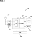
- FIG. 2 shows an exemplary internal configuration of terminal device 102 according to some aspects, which may include antenna system 202, radio frequency (RF) transceiver 204, baseband modem 206 (including digital signal processor 208 and controller 210 ), application processor 212, memory 214, and power supply 216.
- RF radio frequency
- Terminal device 102 may transmit and receive radio signals on one or more radio access networks.
- Baseband modem 206 may direct such communication functionality of terminal device 102 according to the communication protocols associated with each radio access network, and may execute control over antenna system 202 and RF transceiver 204 to transmit and receive radio signals according to the formatting and scheduling parameters defined by each communication protocol.
- baseband modem 206 may include digital signal processor 208, which may perform physical layer (PHY, Layer 1) transmission and reception processing to, in the transmit path, prepare outgoing transmit data provided by controller 210 for transmission via RF transceiver 204, and, in the receive path, prepare incoming received data provided by RF transceiver 204 for processing by controller 210.
- Digital signal processor 208 may be configured to perform one or more of error detection, forward error correction encoding/decoding, channel coding and interleaving, channel modulation/demodulation, physical channel mapping, radio measurement and search, frequency and time synchronization, antenna diversity processing, power control and weighting, rate matching/de-matching, retransmission processing, interference cancelation, and any other physical layer processing functions.
- digital signal processor 208 may include one or more dedicated hardware circuits (e.g., ASICs, FPGAs, and other hardware) that are digitally configured to specific execute processing functions.
- the one or more processors of digital signal processor 208 may offload certain processing tasks to these dedicated hardware circuits, which are referred to herein as hardware accelerators.
- Exemplary hardware accelerators can include Fast Fourier Transform (FFT) circuits and encoder/decoder circuits.
- FFT Fast Fourier Transform
- the processor and hardware accelerator components of digital signal processor 208 may be realized as a coupled integrated circuit.
- Power supply 216 may be an electrical power source that provides power to the various electrical components of terminal device 102. Depending on the design of terminal device 102, power supply 216 may be a 'definite' power source such as a battery (e.g., rechargeable or disposable) or an 'indefinite' power source such as a wired electrical connection. Operation of the various components of terminal device 102 may thus pull electrical power from power supply 216.
- a 'definite' power source such as a battery (e.g., rechargeable or disposable) or an 'indefinite' power source such as a wired electrical connection. Operation of the various components of terminal device 102 may thus pull electrical power from power supply 216.
- terminal devices 102 and 104 may execute mobility procedures to connect to, disconnect from, and switch between available network access nodes of the radio access network of radio communication network 100.
- each network access node of radio communication network 100 may have a specific coverage area (one or more of which can be overlapping or mutually exclusive)
- terminal devices 102 and 104 may be configured to select and re-select between the available network access nodes to maintain a suitable radio access connection with the radio access network of radio communication network 100.
- terminal device 102 may establish a radio access connection with network access node 110 while terminal device 104 may establish a radio access connection with network access node 114.
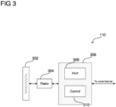
- FIG. 3 shows an exemplary internal configuration of a network access node, such as network access node 110, according to some aspects.
- network access node 110 may include antenna system 302, radio transceiver 304, and baseband subsystem 306 (including physical layer processor 308 and controller 310 ).
- antenna system 302 may be an antenna array including multiple antennas.
- Radio transceiver 304 may perform transmit and receive RF processing to convert outgoing baseband samples from baseband subsystem 306 into analog radio signals to provide to antenna system 302 for radio transmission and to convert incoming analog radio signals received from antenna system 302 into baseband samples to provide to baseband subsystem 306.
- FIG. 4 shows an exemplary configuration in accordance with some aspects where network access node 110 interfaces with core network 402, which may be, for example, a cellular core network.
- Core network 402 may provide a variety of functions to manage operation of radio communication network 100, such as data routing, authenticating and managing users/subscribers, interfacing with external networks, and various other network control tasks. Core network 402 may therefore provide an infrastructure to route data between terminal device 104 and various external networks such as data network 404 and data network 406.
- Terminal device 104 may thus rely on the radio access network provided by network access node 110 to wirelessly transmit and receive data with network access node 110, which may then provide the data to core network 402 for further routing to external locations such as data networks 404 and 406 (which may be packet data networks (PDNs)). Terminal device 104 may therefore establish a data connection with data network 404 and/or data network 406 that relies on network access node 110 and core network 402 for data transfer and routing.
- data networks 404 and 406 which may be packet data networks (PDNs)
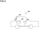
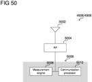
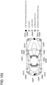
- FIG. 5 shows an exemplary internal configuration of a vehicular communication device 500 according to some aspects.
- vehicular communication device 500 may include steering and movement system 502, radio communication arrangement 504, and antenna system 506.
- the internal components of vehicular communication device 500 may be arranged around a vehicular housing of vehicular communication device 500, mounted on or outside of the vehicular housing, enclosed within the vehicular housing, or any other arrangement relative to the vehicular housing where the internal components move with vehicular communication device 500 as it travels.
- the vehicular housing such as an automobile body, plane or helicopter fuselage, boat hull, or similar type of vehicular body dependent on the type of vehicle that vehicular communication device 500 is.
- Steering and movement system 502 may include components of vehicular communication device 500 related to steering and movement of vehicular communication device 500.
- vehicular communication device 500 is an automobile
- steering and movement system 502 may include wheels and axles, an engine, a transmission, brakes, a steering wheel, associated electrical circuitry and wiring, and any other components used in the driving of an automobile.
- vehicular communication device 500 is an aerial vehicle
- steering and movement system 502 may include one or more of rotors, propellers, jet engines, wings, rudders or wing flaps, air brakes, a yoke or cyclic, associated electrical circuitry and wiring, and any other components used in the flying of an aerial vehicle.
- steering and movement system 502 may include any one or more of rudders, engines, propellers, a steering wheel, associated electrical circuitry and wiring, and any other components used in the steering or movement of an aquatic vehicle.
- steering and movement system 502 may also include autonomous driving functionality, and accordingly may also include a central processor configured to perform autonomous driving computations and decisions and an array of sensors for movement and obstacle sensing.
- the autonomous driving components of steering and movement system 502 may also interface with radio communication arrangement 504 to facilitate communication with other nearby vehicular communication devices and/or central networking components that perform decisions and computations for autonomous driving.
- Radio communication arrangement 504 and antenna system 506 may perform the radio communication functionalities of vehicular communication device 500, which can include transmitting and receiving communications with a radio communication network and/or transmitting and receiving communications directly with other vehicular communication devices and terminal devices.
- radio communication arrangement 504 and antenna system 506 may be configured to transmit and receive communications with one or more network access nodes, such as, in the exemplary context of DSRC and LTE V2V/V2X, RSUs and base stations.
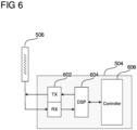
- FIG. 6 shows an exemplary internal configuration of antenna system 506 and radio communication arrangement 504 according to some aspects.
- radio communication arrangement 504 may include RF transceiver 602, digital signal processor 604, and controller 606.
- controller 606 may be included in radio communication arrangement 504 .
- Controller 606 may be responsible for execution of upper-layer protocol stack functions, while digital signal processor 604 may be responsible for physical layer processing.
- RF transceiver 602 may be responsible for RF processing and amplification related to transmission and reception of wireless radio signals via antenna system 506.
- controller 606 may be responsible for upper-layer protocol stack functions.
- Controller 606 may include one or more processors configured to retrieve and execute program code that algorithmically defines the upper-layer protocol stack logic for one or more radio communication technologies, which can include Data Link Layer/Layer 2 and Network Layer/Layer 3 functions.
- Controller 606 may be configured to perform both user-plane and control-plane functions to facilitate the transfer of application layer data to and from radio communication arrangement 504 according to the specific protocols of the supported radio communication technology.
- User-plane functions can include header compression and encapsulation, security, error checking and correction, channel multiplexing, scheduling and priority, while control-plane functions may include setup and maintenance of radio bearers.
- the program code retrieved and executed by controller 606 may include executable instructions that define the logic of such functions.
- radio communication arrangement 504 may be configured to transmit and receive data according to multiple radio communication technologies.
- one or more of antenna system 506, RF transceiver 602, digital signal processor 604, and controller 606 may include separate components or instances dedicated to different radio communication technologies and/or unified components that are shared between different radio communication technologies.
- controller 606 may be configured to execute multiple protocol stacks, each dedicated to a different radio communication technology and either at the same processor or different processors.
- digital signal processor 604 may include separate processors and/or hardware accelerators that are dedicated to different respective radio communication technologies, and/or one or more processors and/or hardware accelerators that are shared between multiple radio communication technologies.
- RF transceiver 602 may include separate RF circuitry sections dedicated to different respective radio communication technologies, and/or RF circuitry sections shared between multiple radio communication technologies.
- antenna system 506 may include separate antennas dedicated to different respective radio communication technologies, and/or antennas shared between multiple radio communication technologies. Accordingly, while antenna system 506, RF transceiver 602, digital signal processor 604, and controller 606 are shown as individual components in FIG. 6 , in some aspects antenna system 506, RF transceiver 602, digital signal processor 604, and/or controller 606 can encompass separate components dedicated to different radio communication technologies.
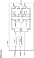
- FIG. 7 shows an example in which RF transceiver 602 includes RF transceiver 602a for a first radio communication technology, RF transceiver 602b for a second radio communication technology, and RF transceiver 602c for a third radio communication technology.
- digital signal processor 604 includes digital signal processor 604a for the first radio communication technology, digital signal processor 604b for the second radio communication technology, and digital signal processor 604c for the third radio communication technology.
- controller 606 may include controller 606a for the first radio communication technology, controller 606b for the second radio communication technology, and controller 606c for the third radio communication technology.
- RF transceiver 602a, digital signal processor 604a, and controller 606a thus form a communication arrangement (e.g., the hardware and software components dedicated to a particular radio communication technology) for the first radio communication technology
- RF transceiver 602b, digital signal processor 604b, and controller 606b thus form a communication arrangement for the second radio communication technology
- RF transceiver 602c, digital signal processor 604c, and controller 606c thus form a communication arrangement for the third radio communication technology.
- More or less radio communication technologies may be implemented. While depicted as being logically separate in FIG. 7 , any components of the communication arrangements may be integrated into a common component or set of common components.
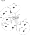
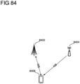
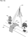
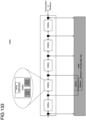
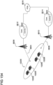
- FIG. 8 shows an exemplary network scenario including various vehicular radio communication technologies according to some aspects.
- vehicular communication devices 810 and 876 may operate in broadband network 802, which may use, for example, any type of cellular radio communication technology.
- Vehicular communication devices 810 and 876 may communicate with each other using sidelink channel 840, such as using DSRC, LTE V2V, LTE D2D, or another vehicular radio communication technology for sidelink communications.
- Vehicular communication device 810 may communicate with infrastructure 828 (e.g., a traffic light, camera, lane marker, street light, traffic signs, parking meters) over channel 854 using a cellular radio communication technology, while vehicular communication device 876 may communicate with network access node 842 (e.g., LTE base station) over channel 864. Vehicular communication device 876 may also communicate with RSU 832 over channel 852, which may use a short-range radio communication technology, such as DSRC. Network access node 842 may interface with IoT/narrowband network 874 over backhaul link 872. Vehicular communication device 810 may travel on road 806.
- infrastructure 828 e.g., a traffic light, camera, lane marker, street light, traffic signs, parking meters
- network access node 842 e.g., LTE base station
- RSU 832 e.g., LTE base station
- RSU 832 e.g., LTE base station
- Network access node 842 may interface
- Vehicular communication devices 824, 878, and 812 may operate in broadband network 880, which may use the same or a different cellular radio communication technology from broadband network 802. As shown in FIG. 8 , vehicular communication devices 878 and 824 may communicate over sidelink channel 892. Vehicular communication devices 812 and 878 may communicate with network access node 840 over channels 866 and 868, respectively. Vehicular communication device 824 may communicate with RSU 834 over channel 856. Network access node 840 may interface with vehicular communication devices 820 and 822 located in IoT/narrowband network 874 over channels 870 and 882. Vehicular communication device 824 may travel on road 808.
- Vehicular communication devices 884, 886, and 818 may operate in short-range/unlicensed network 805, which may use any type of short-range radio communication technology, for example, DSRC or WiFi. Vehicular communication devices 884 and 818 may communicate with each other on sidelink channel 850, while vehicular communication devices 884 and 886 may communicate with each other on sidelink channel 844. Vehicular communication device 818 may communicate with infrastructure 888 on sidelink channel 862, and vehicular communication device 886 may communicate with RSU 838 on channel 860.
- Vehicular communication devices 816 and 826 may operate in short-range/unlicensed network 890, where vehicular communication device 826 may communicate with vehicular communication device 816 on sidelink channel 848 and vehicular communication device 816 may communicate with RSU 836 on channel 858.
- Vehicular communication devices 884 and 814 may be located outside of network coverage, and may use radar sensing over channel 846 to detect each other.
- a vehicular communication devices arranges to form a cluster of vehicular communication devices that coordinates to manage access to channel resources in a distributed manner.
- a vehicular communication device assumes the role of a cluster head, and organizes one or more other vehicular communication devices to form a cluster that coordinate to efficiently manage access to shared channel resources.
- the cluster head performs tasks such as initial formation of the cluster, management of the cluster during operation, and termination of the cluster.
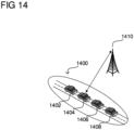
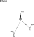
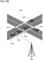
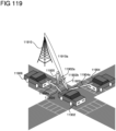
- FIG. 9 shows an exemplary illustration of this cluster-based distributed channel access according to some aspects.
- cluster 900 may include vehicular communication devices 902, 904, 906, and 908, while cluster 910 may include vehicular communication device 912, 914, 916, and 918.
- the vehicular communication devices of clusters 900 and 910 may coordinate to manage access to channel resources that can be shared between multiple vehicular radio communication technologies, such as DSRC, LTE V2V/V2X, and any other vehicular radio communication technologies.
- this cluster-based distributed channel access approach can facilitate efficient management and sharing of channel resources even when no central or coordinated infrastructure is available to perform.
- this is exemplary and vehicular communication devices 902, 904, 906, and 908 and vehicular communication device 912, 914, 916, and 918 may be the same or may be different types of vehicular communication device.
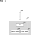
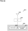
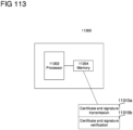
- FIG. 10 shows an exemplary internal configuration of a vehicular communication device acting as a cluster head
- FIG. 11 shows an exemplary internal configuration of a vehicular communication device that is a member of a cluster
- a cluster head may include antenna system 1002 and communication arrangement 1004.
- Antenna system 1002 may be configured in the manner of antenna system 506 as shown and described for vehicular communication device 500 in FIG. 5 . Accordingly, in the transmit direction antenna system 1002 may be configured to receive electrical radio signals from communication arrangement 1004 and to transmit the electrical radio signals as wireless radio signals. In the receive direction, antenna system 1002 may be configured to receive and transduce wireless radio signals to obtain electrical radio signals, which antenna system 1002 may provide to communication arrangement 1004 for further processing.
- communication arrangement 1004 may include RF transceiver 1006, resource allocator 1008, and cluster manager 1010.
- Communication arrangement 1004 may correspond to communication arrangement 504 as previously shown and described for vehicular communication device 500 in FIGs. 5 and 6 .
- RF transceiver 1006 may therefore be configured in the manner of RF transceiver 602, and, in the transmit direction, may process baseband samples to produce radio signals for transmission by antenna system 1002 and, in the receive direction, may process radio signals to produce baseband samples.
- Resource allocator 1008 and cluster manager 1010 may be physical layer, protocol stack, or application layer components, and, although not specifically limited to any particular implementation, may be part of one or more of a digital signal processor or controller of communication arrangement 1004 (e.g., as in digital signal processor 604 and controller 606 of vehicular communication device 500 ).
- Resource allocator 1008 is a processor configured to retrieve (e.g., from a local memory) and execute program code that algorithmically defines the allocation of channel resources for members of a cluster in the form of executable instructions.
- the program code executed by resource allocator 1008 may be an allocation subroutine.
- the allocation subroutine may define a procedure for identifying an overall pool of channel resources (e.g., all of the channel resources that are available for use by the vehicular communication devices of a cluster), identifying the vehicular communication devices of the cluster, determining which channel resources should be allocated to which vehicular communication device, and other allocation-related functions described herein.
- the allocation subroutine may consider other information such as the past channel resource usage (e.g., the total amount of spectrum used, the total amount of transmissions, and/or the total amount of data transferred in a time window) of the vehicular communication devices, and may allocate more channel resources to vehicular communication devices that use more channel resources (e.g., use more spectrum, perform more transmissions, and/or transfer more data).
- the allocation subroutine may then select channel resources (e.g., specific subcarriers in specific time slots) for the vehicular communication devices, and may generate a channel resource allocation (e.g., a message in a predefined format) that specifies the channel resources allocated to the vehicular communication devices.
- resource allocator 1008 can be a protocol stack component, such as a Media Access Control (MAC) scheduler of a controller of the cluster head.
- MAC Media Access Control
- Cluster manager 1010 may be a processor configured to retrieve (e.g., from a local memory) and execute program code that algorithmically defines the management of vehicular communication devices in a cluster in the form of executable instructions.
- the program code executed by cluster manager 1010 may be a cluster management subroutine.
- the cluster management subroutine may define the procedure for generating and terminating clusters, adding and removing vehicles from clusters, communicating with other clusters, generation and transmission of cluster signaling to other vehicular communication devices in the cluster, and other cluster management-related functions described herein.
- the program code may be updatable, such as wirelessly or by a manual install.
- cluster manager 1010 may be an application layer component, and may be part of a controller of the cluster head.
- FIG. 11 shows an exemplary internal configuration of a vehicular communication device that is a member of a cluster (e.g., a cluster member).
- the vehicular communication device may include antenna system 1102, which may be configured in the manner of antenna system 506 as shown and described for vehicular communication device 500 in FIG. 5 .
- antenna system 1102 may be configured to receive electrical radio signals from communication arrangement 1104 and to transmit the electrical radio signals as wireless radio signals.
- antenna system 1102 may be configured to receive and transduce wireless radio signals to obtain electrical radio signals, which antenna system 1102 may provide to communication arrangement 1104 for further processing.
- Cluster manager 1110 may be a processor configured to retrieve (e.g., from a local memory) and execute program code that algorithmically defines the cluster behavior of the vehicular communication device in the form of executable instructions.
- the program code may be updatable, such as wirelessly or by a manual install.
- the program code executed by cluster manager 1110 may be a cluster management subroutine.
- the cluster management subroutine may define the procedure for joining and exiting clusters, selecting cluster heads, transmitting and receiving cluster signaling with a cluster head and other members of the cluster, and other cluster management-related functions described herein.
- cluster manager 1110 may be an application layer component, and may be part of a controller of the vehicular communication device.
- cluster heads may also use an inter-cluster link to coordinate movement of the clusters. For example, if the vehicular communication devices of cluster 900 are moving along a current route and the vehicular communication devices of cluster 910 are blocking the path of the vehicular communication devices of cluster 900, cluster head 904 may transmit a request to cluster head 914 that requests for cluster 910 to move out of the way of cluster 900. Cluster head 914 may then transmit cluster signaling to vehicular communication devices 912, 916, and 918 with instructions to move out of the way of cluster 900. If the vehicular communication devices are autonomous vehicles, and accordingly have autonomous driving functionality as part of their steering and movement systems, the vehicular communication devices may respond to such a request by autonomously steering out of the way. If the vehicular communication devices are driver-operated, the vehicular communication devices may present a visual or audibly notification to the drive to move out of the way.
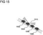
- FIG. 15 shows an example of a greedy spectrum selection according to some aspects.
- vehicular communication device 1504 may decide to communicate with neighboring vehicular communication devices and/or network access nodes using one or more vehicular radio communication technologies, such as DSRC or LTE V2X/V2X.
- Vehicular communication device 1504 may then identify a suitable channel on which to transmit and receive the communications.
- vehicular communication device 1504 may perform radio sensing on multiple channels (e.g., with its scheduler 1108) to identify a channel that is available (e.g., that is not occupied according to a listen-before-talk (LBT) scheme) or that has minimal interference (e.g., with the least interference out of the multiple channels that are evaluated).
- LBT listen-before-talk
- Vehicular communication device 1504 may then broadcast signaling 1510 to neighboring vehicular communication devices 1502, 1506, and 1508 that specifies the selected channel that vehicular communication device 1504 intends to use for communications.
- vehicular communication device 1504 may also determine scheduling information that identifies the time slot(s) and/or vehicular radio communication technology(ies) for which vehicular communication device 1504 intends to access the selected channel.
- Vehicular communication device 1504 may then include such scheduling information in signaling 1510.
- Nearby vehicular communication devices, such as vehicular communication devices 1502, 1506, and 1508, may then receive signaling 1510 and consequently identify the scheduling and the vehicular radio communication technologies with which vehicular communication device 1504 intends to use the channel.
- vehicular communication devices 1502, 1506, and 1508 may then schedule or adjust their own radio communications based on the information in signaling 1510, such as to help avoid collisions and interference.
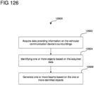
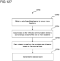
- vehicular communication device 1504 may base the channel and scheduling selection on the capabilities and scheduling of nearby vehicular communication devices. For example, since vehicular communication devices may exchange basic safety messages and other movement information with nearby vehicular communication devices, coordination in channel selection and scheduling may be useful in enabling all nearby vehicular communication devices to communicate with each other.
- vehicular communication devices may broadcast signaling that indicates a ranked list of preferred channels and/or vehicular radio communication technologies, which may assist during the negotiation process in agreeing on a channel and/or vehicular radio communication technology that is supported by some or all negotiating vehicular radio communication devices.
- Vehicular communication devices 1502-1508 can then begin transmitting and receiving using the agreed channels and/or vehicular radio communication technologies.
- vehicular communication devices may also negotiate in this manner to agree on time slots allocated to each vehicular communication device on a given channel, which can provide fair access to the channel.
- this greedy spectrum selection approach can be used in conjunction with cluster-based communications.
- vehicular communication devices 1502-1508 may all be members of the same cluster.
- the cluster head such as vehicular communication device 1504
- the cluster head may communicate with a cluster head of another cluster, such as cluster head 914, to identify the overall pool of channel resources and/or vehicular radio communication technologies available for the members of its cluster to use for greedy spectrum selection.
- cluster head 904 may negotiate with cluster head 914 (e.g., with their respective cluster managers 1010) via inter-cluster link 920 to identify the overall pool of channel resource available for each cluster to use for greedy spectrum selection.
- cluster head 904 and cluster head 914 may compete with each other using greedy spectrum selection to secure channel resources for their respective clusters to use.
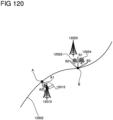
- control server 1612 may also assist in managing interference between different vehicular radio access technologies by acting as a database of network access nodes.
- cluster head 1604 may document network access nodes that cluster 1600 observes during travel, and report the network access nodes to control server 1612.
- one or more of cluster head 1604 or vehicular communication devices 1602, 1606, and 1608 may detect various network access nodes during travel (e.g., via reception of discovery signaling), and may record the location, identity, and channel resource usage of the detected network access nodes.
- Cluster head 1604 may then report this information of the detected network access nodes to control server 1612.
- Control server 1612 may then use this information for the detected network access nodes to make decisions on channel resource allocations for cluster 1600 and/or other clusters.
- network access nodes can thus communicate with control server 1612, which may act as a database, to obtain location, identity, and channel resource usage information (e.g., the channels and time slots that network access nodes are using) for network access nodes supporting other vehicular radio communication technologies.
- Network access nodes can then use this information either with or without cluster-based channel access.
- a network access node may provide the location, identity, and channel resource usage information to a cluster head.
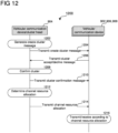
- the cluster head may then determine channel resource allocations (e.g., in the manner of stage 1212 of FIG. 12 ) based on the information, such as by avoiding allocating channel resources to its cluster that are being used by nearby network access nodes.
- control server 1612 or the network access node may determine the channel resource allocations for a given cluster based on the information, and may then transmit the channel resource allocations to the cluster head of the cluster.
- network access nodes such as LTE V2V/V2X base stations may similarly determine channel resource allocations for individual vehicular communication devices based on the information, such as by avoiding allocating channel resources to vehicular communication devices that are being used by nearby network access nodes.
- network access nodes that support different vehicular radio communication technologies may interface directly to coordinate access to shared channel resources.
- DSRC RSUs and LTE V2V/V2X base stations can negotiate with each other to coordinate access to shared channel resources.
- the negotiation can include exchanging channel information between network access nodes, where, for example, a first network access node can specify to a second network access node which channel resources it has allocated or is immediately planning to allocate for use. The second network access node can then make an independent decision to use different channel resources.
- network access nodes may utilize more elaborate coordination scheme, such as a request-response protocol.
- a first network access node may request the use of channel resources (e.g., a certain channel during certain time slots), and the second network access node may then respond with an acceptance, rejection, or counter-proposal.
- channel resources e.g., a certain channel during certain time slots
- the negotiations can take place on the application layer (e.g., above transport/IP layers) over a software-level connection, where the underlying radio protocols differ according to the different vehicular radio communication technologies.
- the negotiations may attempt to target an optimum working point for coordination between different vehicular radio communication technologies. For example, contention-based channel access schemes may see a sizable drop in efficiency if the channel load reaches 60 percent or more.
- network access nodes that are negotiating may coordinate to obtain shared access in which contention-based channel access schemes such as DSRC have a channel load of less than 60 percent. In some aspects, these negotiations may occur through a central control entity, such as control server 1612.
- the implementations described herein may be used across multiple bands.
- the channel resource allocations described herein may apply to channels across multiple bands, such as channels on both the 3.4-3.8 GHz and 5.9 GHz bands.
- different band may use differing levels of coordination to manage access.
- clusters on some bands may use cluster-based coordination, while individual vehicular communication devices or clusters may use greedy spectrum selection on other bands.
- carrier aggregation may also be used, potentially also with differing levels of coordination on the separate carriers.
- a cluster may use carrier aggregation, where individual vehicular communication devices of the cluster may compete for channel resources on a first band according to greedy spectrum selection while coordinating under the guidance of the cluster head to obtain channel resources on a second band.
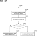
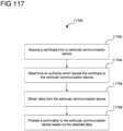
- FIG. 17 shows method 1700 of performing vehicular radio communications according to some aspects.
- method 1700 includes identifying a plurality of vehicular communication devices of a cluster of cooperating vehicular communication devices (1702), determining channel resource allocations for the plurality of vehicular communication devices that includes first channel resources allocated for a first vehicular radio communication technology and second channel resources allocated for a second vehicular radio communication technology (1704), and transmitting the channel resource allocation to the plurality of vehicular communication devices (1706).
- the aspects described above regarding distributed coexistence management for vehicular radio communication technologies may operate in a relatively decentralized manner. Coexistence between different vehicular radio communication technologies may additionally or alternatively be managed with more centralized approaches.
- a central control entity may assume the primary role in determining channel resource allocations between different vehicular radio communication technologies.
- vehicular radio communication technologies such as DSRC and LTE V2V/V2X are independent and in many cases operated by different network operators, this central control entity may be a system-independent global controller.
- the central control entity may monitor channel resource usage by the vehicular radio communication technologies, determine channel resource allocations for the vehicular radio communication technologies, and broadcast the channel resource allocations to the various terminal devices and network access nodes using the vehicular radio communication technologies.
- DSRC may prove easier to deploy in the near future than LTE V2V/V2X, potentially due in part to the fact that the distributed nature of DSRC allows deployment without substantial network coordination and support.
- LTE V2V/V2X may be slower than that of DSRC
- LTE V2V/V2X may prove to be the more useful and widespread technology due to its favorable compatibility with 5G network architectures. Accordingly, initial heavy usage of DSRC may eventually migrate to LTE V2V/V2X, and channel resource usage of LTE V2V/V2X may therefore grow in proportion to that of DSRC over time.
- the central control entity may therefore be able to play a role in this transition (and other analogous transitions) by gradually allocating a greater proportion of channel resources to LTE V2V/V2X over time.
- the central control entity may similarly be able to handle migration between radio communication technologies over time (e.g., a third, a fourth, etc.), and is thus not limited to any particular two radio communication technologies.
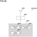
- RAN-supported implementations may use support provided by the network access nodes of the radio access network to supply the central control entity with channel resource usage information and to transmit channel resource allocations to participating communication devices.
- RAN-independent implementations may use separate infrastructure, such as a network of remote nodes with radio-sensing capabilities, to supply channel resource usage information to the central control entity and to transmit channel resource allocations to participating vehicular communication devices.
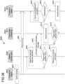
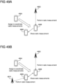
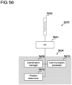
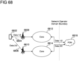
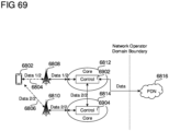
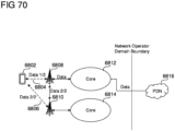
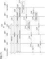
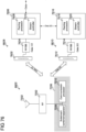
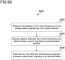
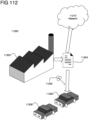
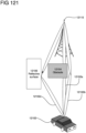
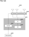
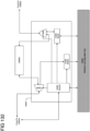
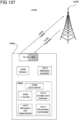
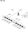
- FIG. 18 shows an example of a RAN-supported implementation according to some aspects.
- network access node 1808 may serve vehicular communication device 1802
- network access node 1810 may serve vehicular communication devices 1804 and 1806.
- Network access node 1808 and vehicular communication device 1802 may be configured to support a first vehicular radio communication technology, such as DSRC
- network access node 1810 and vehicular communication devices 1804 and 1806 may be configured to support a second vehicular radio communication technology, such as LTE V2V/V2X. While examples may refer to first and second vehicular radio communication technologies, these examples can be scaled to any number of vehicular radio communication technologies.
- coexistence engine 1812 may function to coordinate channel resource usage between these different vehicular radio communication technologies, in addition to other communication technologies.
- coexistence engine 1812 may monitor channel resource usage and determine channel resource allocations for the different vehicular radio communication technologies. Coexistence engine 1812 may then provide the channel resource allocations to the participating communication devices via the radio access network.
- Coexistence engine 1812 may be a server-type component, and may include one or more processors configured to retrieve (e.g., from a non-transitory computer readable medium) and execute program code that algorithmically defines the functionality of coexistence engine 1812 described herein. As shown in FIG. 18 , coexistence engine 1812 may interface with network access nodes 1808 and 1810. In some aspects, coexistence engine 1812 may be located in the core network, such as a core network behind network access node 1808 or a core network behind network access node 1810. In some aspects, coexistence engine 1812 may be independently located outside of the network domain of both network access nodes 1808 and 1810.
- Coexistence engine 1812 may therefore interface with network access nodes 1808 and 1810 over a backhaul link, which may run through a core network or may interface directly between coexistence engine 1812 and network access nodes 1808 and 1810].
- coexistence engine 1812 may be a RAN component that is locally positioned at network access node 1808 or 1810, and may interface with the other of network access nodes 1808 or 1810 via a backhaul link.
- Coexistence engine 1812 may transmit and receive data via a logical software-level connection, such as to and from a core network, network access nodes, and/or remote nodes over wired or wireless interfaces.
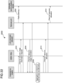
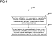
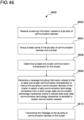
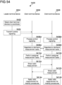
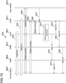
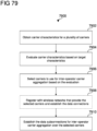
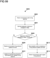
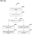
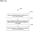
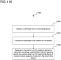
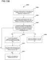
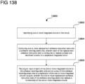
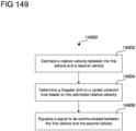
- FIG. 19 shows method 1900 illustrating this process according to some aspects, which coexistence engine 1812 may perform via execution of software instructions at one or more processors.
- coexistence engine 1812 may first receive channel resource usage information from reporting communication devices in stage 1902.
- vehicular communication devices 1802-1806 may be within the coverage of network access nodes 1808 and 1810.
- network access node 1808 may be a DSRC RSU within radio range of vehicular communication device 1802
- network access node 1810 may be an LTE V2V/V2X base station within radio range of vehicular communication devices 1804 and 1806.
- network access nodes 1808 and 1810 may be aware of their own channel resource usage and the channel resource usage of their served vehicular communication devices.
- network access node 1810 may be responsible for scheduling uplink and downlink communications and may thus know the uplink and downlink channel resource usage information. For example, network access node 1810 may locally retain the channels used for uplink and downlink communications optionally in addition to the time slots during which the channels are used, transmission powers, spatial multiplexing layers (e.g., specific spatial multiplexing slots, such as MIMO transmission having tight angular restrictions), and other scheduling parameters.
- LTE V2V/V2X base station or other network access node that performs deterministic scheduling, including DSRC RSUs if later DSRC versions have centrally managed or deterministic scheduling
- network access node 1810 may be responsible for scheduling uplink and downlink communications and may thus know the uplink and downlink channel resource usage information. For example, network access node 1810 may locally retain the channels used for uplink and downlink communications optionally in addition to the time slots during which the channels are used, transmission powers, spatial multiplexing layers (e.g., specific spatial multiplexing slots, such as MIMO transmission
- Network access node 1810 may also know the number of active users (e.g., terminal devices) that it is serving, and/or efficiency parameters such as the retransmission rate for its served users.
- the channel resource usage information may therefore include one or more of spectrum used, spectrum used per unit time (e.g., the total spectrum used in a given time period), spectrum used per unit time and spatial multiplexing layer (e.g., where each spatial multiplexing layer can duplicate the channel resource), spectrum used per unit time, spatial multiplexing layer, code (e.g., for code division multiplexing for overlaying codewords), polarization (e.g., horizontal vs.
- Network access node 1810 may transmit this channel resource usage information to coexistence engine 1812, which coexistence engine 1812 may receive in stage 1902.
- network access node 1808 may not have direct knowledge of the uplink and downlink scheduling and may thus not locally retain channel resource usage information.
- network access node 1808 may perform sensing to obtain the channel resource usage information.
- network access node 1808 may receive and process radio signals according to the first vehicular radio communication technology, which can include transmissions by vehicular communication device 1802 and any other vehicular communication devices or network access nodes with the first vehicular radio communication technology. This can include performing a frequency scan to detect which channels contain active transmissions.
- Network access node 1808 may thus determine which channels vehicular communication device 1802 is transmitting on, which time slots vehicular communication device 1802 is using the channels, which transmit powers vehicular communication device 1802 is using, which spatial multiplexing layer vehicular communication device 1802 is using, and other such scheduling parameters.
- the channel resource usage information can include one or more of spectrum used, spectrum used per unit time, spectrum used per unit time and spatial multiplexing layer, spectrum used per unit time/spatial multiplexing layer/code/polarization/propagation channel orthogonality, a total airtime of transmissions, a total number of active users, a total transmit power of transmissions, a total amount of data transmitted, a transmission efficiency, or one or more other metrics that indicate the load or usage of channel resources by network access node 1810 and the users it serves.
- Network access node 1808 may thus determine this channel source usage information using radio sensing and then transmit this channel resource usage information to coexistence engine 1812, which coexistence engine 1812 may receive in stage 1902.
- vehicular communication devices may perform this radio sensing to obtain the channel resource usage information in RAN-supported implementations.
- vehicular communication device 1802 may receive and process radio signals according to the first vehicular radio communication technology, which can include transmissions by other vehicular communication devices and network access nodes with the first vehicular radio communication technology. This can include performing a frequency scan to detect which channels contain active transmissions.
- Vehicular communication device 1802 may then determine the channel resource usage information based on the received radio signals, and may report the channel resource usage information to network access node 1808.
- Network access node 1808 may then report the channel resource usage information to coexistence engine 1812, which coexistence engine 1812 may receive in stage 1902.
- vehicular communication device 1802 may relay the channel resource usage information to network access node 1808, such as through one or more other vehicular communication devices that act as a relaying link.
- Network access node 1808 may then send the channel resource usage information to coexistence engine 1812.
- coexistence engine 1812 may determine the channel resource allocations specific to particular geographic areas. For example, coexistence engine 1812 can aggregate the channel resource usage information from reporting communication devices located in a first area, and separately aggregate the channel resource usage information from reporting communication devices located in a different second area. Coexistence engine 1812 may thus obtain first and second aggregated channel resource usage information for both the first area and second area. Coexistence engine 1812 may then separately determine the channel resource allocations for the first area and second area using the corresponding aggregated channel resource usage information.
- coexistence engine 1812 may also adapt to more long-term fluctuations in relative channel resource usage between different vehicular radio communication technologies. For example, DSRC may see widespread use during early deployment stages compared to LTE V2V/V2X, which may not be fully deployed and operation until months or years after DSRC. Accordingly, channel resource usage may initially be heavily slanted towards DSRC relative to LTE V2V/V2X. However, as LTE V2V/V2X is expected to better integrate into the 5G network architecture, LTE V2V/V2X may gradually catch up and eventually overtake DSRC in terms of channel resource usage.
- coexistence engine 1812 may continue to determine channel resource allocations based on the observed channel resource usage as indicated by channel resource usage information, coexistence engine 1812 may as a result adapt the channel resource allocations to gradually favor LTE V2V/V2X over DSRC.
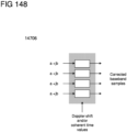
- FIG. 23 shows two examples of long-term transitions in resource usage allocations between a first vehicular radio communication technology and second vehicular radio communication technology, such as for a transition from DSRC to LTE V2V/V2X.
- Both examples 2310 and 2320 assume a gradual and long-term (e.g., in the order of months or years) transition between widespread DSRC use to widespread LTE V2V/V2X use, and depict the relative amounts of spectrum allocated to DSRC and LTE V2V/V2X by coexistence engine 1812.
- coexistence engine 1812 may detect this transition via evaluation of channel resource usage information reported by various reporting communication devices, which may steadily reflect an increasing level of channel resource usage by LTE V2V/V2X relative to DSRC over time.
- coexistence engine 1812 may gradually allocate more channel resources to LTE V2V/V2X relative to DSRC over time.
- the transition in example 2310 is steeper than the transition of example 2320. Accordingly, if LTE V2V/V2X completely replaces DSRC as in the case of example 2310, coexistence engine 1812 may gradually allocate more channel resources to LTE V2V/V2X relative to DSRC over time until LTE V2V/V2X is allocated all of the channel resources for available vehicular radio communication technologies. In the case of example 2320, LTE V2V/V2X may not completely overtake DSRC in terms of channel resource usage (or may only overtake DSRC over a substantially long period of time). Accordingly, coexistence engine 1812 may slowly allocate more channel resources to LTE V2V/V2X relative to DSRC.
- Coexistence engine 1812 may therefore react to overall and long-term changes in channel resource usage by different vehicular radio communication technologies by allocating more channel resource levels to some vehicular radio communication technologies relative to others. While the gradual trend may skew towards certain vehicular radio communication technologies that are using more channel resources, coexistence engine 1812 may still perform channel resource allocations dynamically over short-term bases. For example, even if coexistence engine 1812 is gradually allocating more channel resources to LTE V2V/V2X, if coexistence engine 1812 identifies that DSRC is using more channel resources than LTE V2V/V2X at a given point in time, coexistence engine 1812 may determine channel resource allocations that allocate more channel resources to DSRC. The gradual trend shown in FIG.
- coexistence engine 1812 may determine channel resource allocations that allocate more channel resources to DSRC in these areas (while favoring LTE V2V/V2X in other areas where LTE V2V/V2X channel resource usage is higher).
- coexistence engine 1812 may perform channel resource allocation dependent on reported channel resource usage information, while in other aspects coexistence engine 1812 may receive external configuration information that instructs coexistence engine 1812 to favor certain vehicular radio communication technologies over others. For example, if a network operator determines that a transition from a first vehicular radio communication technology to another vehicular radio communication technology should be accelerated, the network operator (e.g., a human actor) can input external configuration information into coexistence engine 1812 that instructs coexistence engine 1812 to allocate more channel resources to the first vehicular radio communication technology (e.g., more channel resources than would be justified if based solely on the reported channel resource usage information).
- the network operator e.g., a human actor
- Coexistence engine 1812 is applicable for use in dynamic scheduling on short-term bases, and a long-term, gradual trend in channel resource usage by different vehicular radio communication technologies is only one exemplary long-term use.
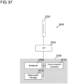
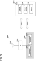
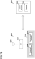
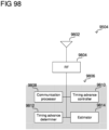
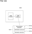
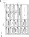
- FIG. 24 shows an exemplary internal configuration of coexistence engine 1812 according to some aspects.
- coexistence engine 1812 may include processor 2402, interface circuitry 2404, and memory 2406.
- Processor 2402 may be a single processor or multiple processors, and may be configured to retrieve (e.g., from a local memory) and execute program code to perform the transmission and reception, channel resource usage information evaluation, and channel resource allocation determination as described herein.
- the program code may be updatable, such as wirelessly or by a manual install.
- Memory 2406 may be a non-transitory computer readable medium storing instructions for interface subroutine 2406a, evaluation subroutine 2406b, and allocation subroutine 2406c.
- Interface subroutine 2406a, evaluation subroutine 2406b, and allocation subroutine 2406c may each be an instruction set including executable instructions that, when retrieved and executed by processor 2402, perform the functionality of processor 2402 as described herein.
- processor 2402 may execute interface subroutine 2406a to transmit and receive communication data via interface circuitry 2404, which may be hardware circuitry that transmits and receives data over one or more wired connections between coexistence engine 1812 and various remote nodes, network access nodes, and/or core network components.
- Processor 2402 can therefore receive channel resource usage information and transmit channel resource allocations via interface circuitry 2404 by executing of interface subroutine 2406a.
- Processor 2402 may execute evaluation subroutine 2406b to process and aggregate channel resource usage information received via interface circuitry 2404. Accordingly, evaluation subroutine 2406b may include instructions to identify channel resource usage information such as one or more of spectrum used, spectrum used per unit time, spectrum used per unit time and spatial multiplexing layer, spectrum used per unit time/spatial multiplexing layer/code/polarization/propagation channel orthogonality, a total airtime of transmissions, a total number of active users, a total transmit power of transmissions, a total amount of data transmitted, or a transmission efficiency provided by reporting communication devices, which can include processing received channel resource usage information to identify the type of channel resource usage information.
- channel resource usage information such as one or more of spectrum used, spectrum used per unit time, spectrum used per unit time and spatial multiplexing layer, spectrum used per unit time/spatial multiplexing layer/code/polarization/propagation channel orthogonality, a total airtime of transmissions, a total number of active users, a total transmit power of transmissions, a total
- Evaluation subroutine 2406b may also include instructions to aggregate channel resource usage information for different vehicular radio communication technologies, such as identifying the channel resource usage information for the first vehicular radio communication technology (e.g., that detail channel resource usage information of communication devices using the first vehicular radio communication technology) and identifying the channel resource usage information for the second vehicular radio communication technology (e.g., that detail channel resource usage information of communication devices using the second vehicular radio communication technology).
- Evaluation subroutine 2406b may include instructions that aggregate channel resource usage information by summing channel resource usage information from different devices, such as summing the spectrum used by a first communication device, the spectrum used by a second communication device, the spectrum used by a third communication device, and so forth with any type of channel resource usage information. This can produce aggregated channel resource usage information.
- Evaluation subroutine 2406b may also include instructions that aggregate different types of channel resource usage information, which can include using a weighting scheme where different types of channel resource usage information are weighted differently to obtain the aggregated channel resource usage information for each vehicular radio communication technology. Evaluation subroutine 2406b may therefore include executable instructions defining any evaluation functionality of coexistence engine 1812 as algorithmically described above in prose.
- Allocation subroutine 2406c may include instructions to determine channel resource allocations based on the channel resource usage information. This can include instructions to allocate different relative amounts of channel resources to the first vehicular radio communication technology and the second vehicular radio communication technology, such as based on whether the first vehicular radio communication technology and the second vehicular radio communication technology uses more channel resources (which may be indicated by aggregated channel resource usage information obtained via execution of evaluation subroutine 2406b). Allocation subroutine 2406c may include instructions to generate channel resource allocations for participating communication devices that assign the participating communication devices different channel resources to use.
- the relative amount of channel resources assigned to the first vehicular radio communication technology may thus depend on the aggregated channel resource usage information as obtained by evaluation subroutine 2406b.
- Allocations subroutine 2406c may therefore include executable instructions defining any channel resource allocation functionality of coexistence engine 1812 as algorithmically described above in prose.
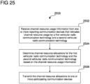
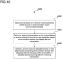
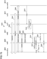
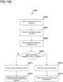
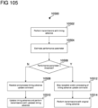
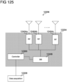
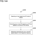
- FIG. 25 shows method 2500 of allocating channel resources to different vehicular radio communication technologies.
- method 2500 includes receiving channel resource usage information from one or more reporting communication devices that indicates channel resource usage by a first vehicular radio communication technology and a second vehicular radio communication technology (2502), determining channel resource allocations for the first vehicular radio communication technology and the second vehicular radio communication technology based on the channel resource usage information (2504), and transmitting the channel resource allocations to one or more participating communication devices (2506).
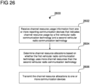
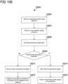
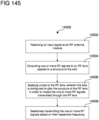
- FIG. 26 shows method 2600 of allocating channel resources to different vehicular radio communication technologies.
- method 2600 includes receiving channel resource usage information from one or more reporting communication devices that indicates channel resource usage by a first vehicular radio communication technology and a second vehicular radio communication technology (2602), determining channel resource allocations based on whether the first vehicular radio communication technology uses more channel resources than the second vehicular radio communication technology (2604), and transmitting the channel resource allocations to one or more communication devices (2606).
- coexistence engine 1812 may determine channel resource allocations for a cluster of vehicular communication devices, which may be based on channel resource usage information provided by the cluster (e.g., via a network access node or remote node) and/or by vehicular communication devices or network access nodes that are using a vehicular radio communication technology supported by the cluster. Coexistence engine 1812 may then transmit the channel resource allocation to the cluster head, which may then assign channel resources for the cluster members to use based on the channel resource allocation.
- vehicular communication devices 902-908 and 912-918 may use different vehicular radio communication technologies in an uncoordinated manner.
- interference between different vehicular radio communication technologies has the potential to lead to collisions, which can severely degrade transmission and reception performance.
- vehicular communication devices attempting to access in some contention-based channel access schemes, such as DSRC may see a sizable drop in efficiency if the channel capacity surpasses a given threshold (e.g., 60 percent).
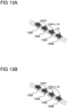
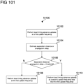
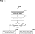
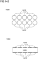
- a resource allocation decision tree is provided to further optimize the assignment of channel resources. More specifically, the resource allocation decision tree provides a mechanism for the assignment of channel resources to at least one of a plurality of terminal devices for a given radio communication network (e.g., V2X, V2V, etc.). Through this interaction, interference may be reduced and resources may be more efficiently utilized over other approaches.
- a radio communication network e.g., V2X, V2V, etc.
- the resource allocation decision tree sets forth a network optimization framework.
- this framework may define a set of rules for the selection and allocation of radio communication technologies for a particular radio communication network. Following the principles outlined herein, resource selection and allocation may be tailored to a radio communication network based on radio communication technology selection criteria associated therewith.
- Radio communication technology selection criteria may include a variety of types of information.
- radio communication technology selection criteria may include parameters based on one or more scenarios, conditions, actions, and/or behaviors of a radio communication network. These parameters may include Key Performance Indicators (KPI), such as those for Long Term Evolution (LTE) Radio Access Networks (RAN).
- KPI Key Performance Indicators
- LTE Long Term Evolution
- RAN Radio Access Networks
- KPI may be grouped into several categories. KPI categories, for instance, may include accessibility, retainability, mobility, utilization, traffic, latency, integrity, security, efficiency, etc. Regardless of their specific classification, exemplary KPI may include packet loss information, throughput information, latency information, and/or one or more other types of information relating to the performance of a particular radio communication network or network device.
- Radio communication technology selection criteria may include quality of service (QoS)-based parameters, such as those for maintaining a minimum QoS level to support a vertical application.
- QoS Class Identifiers may indicate QoS performance characteristics of each packet and control the packet forwarding treatment (e.g., scheduling weights, admission thresholds, queue management thresholds, link layer protocol configuration, etc.).
- a QCI may indicate whether or not a guaranteed bit rate (GBR) is set by the network. In this manner, a guaranteed bandwidth for traffic, such as uplink traffic (UL) or downlink traffic (DL), may be set.
- GBR guaranteed bit rate
- UL uplink traffic
- DL downlink traffic
- QCI may also be associated with a priority level, packet budget delay, packet error loss rate, and/or service type.
- Radio communication technology selection criteria may further include content-based parameters.
- content-based parameters may indicate the degree of importance of the transmitted data.
- each information element or group of information elements may have criticality information applied to it.
- a repeatable information element may have one common criticality information associated therewith or its own criticality information.
- Criticality information may also be applied to non-repeatable information elements. If an information element or group of information elements are not understood or missing, a receiving node may take different actions depending upon the value of the criticality information (e.g., reject, ignore and notify sender, or ignore).
- Radio communication technology selection criteria may further include cluster-based parameters.
- cluster-based parameters may include the number of vehicular communication devices within a cluster.
- Cluster-based parameters may be derived or inferred from cluster state data.
- Cluster state data may indicate which vehicular communication devices are members of the cluster, any relay links therebetween, geographic position, relative position with respect to one another, and/or which member(s) is or has been designated a cluster head. It may further specify which radio access technologies are supported by each vehicular communication device and/or collectively supported.
- Radio communication technology selection criteria may further include device-based parameters.
- device-based parameters may include a user equipment (UE) capability information.
- UE capability information may include a UE-Category, Feature Group Indicators, Carrier Aggregation Band Combination, LTE-related fields, WCDMA related fields, TDSCMA related fields, and/or GSM related fields.
- the UE-Category for instance, may detail a combined UL and DL radio throughput for a UE.
- Radio communication technology selection criteria may further include predictive coverage-based parameters.
- predictive coverage-based parameters may include any of above-described radio communication technology selection criteria associated with location information. Predictive coverage-based parameters may thus describe the expected evolution of the respective radio parameters for one or more vehicular communication devices based on one or more locations, points of interest, directions of movement, velocity indications, inferred routes, explicitly defined routes, route adaptations, weather indications, traffic indications, and/or utility information, etc. Predictive coverage-based parameters may, for instance, be provided from one or more nodes (e.g., vehicular communication devices).
- a resource allocation decision tree may be implemented at one or more entities of the radio communication network.
- Resource allocation decision trees may be implemented in one or more of the vehicular communication devices of this disclosure.
- one or more the vehicular communication devices 902-908 and 912-918 of FIG. 9 may implement the resource allocation decision tree.
- the resource allocation decision tree may be implemented outside of the one or more vehicular communication devices.
- the resource allocation decision tree may be implemented outside of the one or more vehicular communication devices 902-908 and 912-918.
- vehicular communication devices 902-908 and 912-918 may be configured in the manner of vehicular communication device 500 as shown and described for FIGs. 5 and 6 .
- vehicular communication device 500 may be configured to operate according to DSRC and/or LTE V2V/V2X.
- RF transceiver 602, digital signal processor 604, and controller 606 may be configured to transmit and receive communications according to DSRC and/or LTE V2V/V2X.
- the resource allocation decision tree may be implemented within a particular type of vehicular communication device.
- resource allocation decision tree may be implemented at one or more cluster heads (e.g., cluster head 904).
- resource allocator 1008 of cluster head 904 may execute the resource allocation decision tree.
- the resource allocation decision tree may be implemented in a particular type of entity outside of the one or more vehicular communication devices.
- Resource allocation decision tree may, for example, be implemented at one or more control servers (e.g., control server 1612) and/or one or more coexistence engines (e.g., coexistence engine 1812).
- control servers e.g., control server 1612
- coexistence engines e.g., coexistence engine 1812
- control server 1612 may be any of a core network server (e.g., located in a core network behind network access node 1610), a network access node (e.g., an internal component of network access node 1610), or an edge server (e.g., an edge computing device placed between network access node 1610 and a core network).
- control server 1612 may be a server-type component, such as a computing element including one or more processors configured to retrieve (e.g., from a local memory) and execute program code that defines the control and algorithmic functions of control server 1612 as described herein in the form of executable instructions.
- the program code may be updatable, such as wirelessly or by a manual install.
- the one or more processors of control server 1612 may execute the resource allocation decision tree.
- executable program code in control server 1612 may include the resource allocation decision tree.
- the resource allocation decision tree may be implemented within coexistence engine 1812 of FIG. 18 .
- coexistence engine 1812 may include processor 2402, interface circuitry 2404, and memory 2406.
- Processor 2402 may be a single processor or multiple processors, and may be configured to retrieve (e.g., from a local memory) and execute program code to perform the transmission and reception, channel resource usage information evaluation, and channel resource allocation determination as described herein.
- Memory 2406 may be a non-transitory computer readable medium storing instructions for interface subroutine 2406a, evaluation subroutine 2406b, and allocation subroutine 2406c.
- Interface subroutine 2406a, evaluation subroutine 2406b, and allocation subroutine 2406c may each be an instruction set including executable instructions that, when retrieved and executed by processor 2402, perform the functionality of processor 2402 as described herein.
- processor 2402 may execute interface subroutine 2406a to transmit and receive communication data via interface circuitry 2404, which may be hardware circuitry that transmits and receives data over one or more wired connections between coexistence engine 1812 and various remote nodes, network access nodes, and/or core network components.
- Processor 2402 can therefore receive channel resource usage information and transmit channel resource allocations via interface circuitry 2404 by executing of interface subroutine 2406a.
- the processor of coexistence engine 1812 may execute the resource allocation decision tree.
- allocation subroutine 2406c may include the resource allocation decision tree.
- a deciding entity may be a roadside unit (RSU) connected via a LTE link, a device located on the cloud (e.g., backbone network), and/or a communication device (e.g., clustered vehicle) in the V2X or V2V environment, etc.
- RSU roadside unit
- one or more deciding entities may be configured to communicate with one or more vehicular communication devices for radio communication technology selection criteria. For instance, one or more deciding entities may transmit a request for radio communication technology selection criteria to one or more vehicular communication devices.
- vehicular communication device While any vehicular communication device may be polled, some vehicular communication devices may be more capable than others to respond. For instance, one or more vehicular communication devices may be more capable to respond with respect to certain types of radio communication technology selection criteria. In some aspects, an ordered (e.g., prioritized) list of one or more vehicular communication devices capable of responding to a poll may be determined based on received radio communication technology selection criteria and stored by the one or more deciding entities and/or one or more of vehicular communication devices.
- ordered (e.g., prioritized) list of one or more vehicular communication devices capable of responding to a poll may be determined based on received radio communication technology selection criteria and stored by the one or more deciding entities and/or one or more of vehicular communication devices.
- communications for radio communication technology selection criteria are, in some aspects, described as requests for radio communication technology selection criteria
- the descriptions of the communications for radio communication technology selection criteria are also applicable to transmissions of radio communication technology selection criteria.
- descriptions of the communications for radio communication technology selection criteria may, in some aspects, relate to a response addressed to one or more deciding entities comprising radio communication technology selection criteria
- Communications for radio communication technology selection criteria may be sent based on one or more conditions.
- communications for radio communication technology selection criteria may occur at one or more times. These times may refer to point(s) and/or period(s) during which communications for radio communication technology selection criteria may occur.
- communications for radio communication technology selection criteria may be based on a predefined (e.g., scheduled, negotiated, periodic, etc.) condition.
- a deciding entity and/or a vehicular communication device may, for instance, include a timing controller as part of a digital signal processor, controller, and/or application processor.
- the timing controller may be configured to compare a value (e.g., clock) of the timing controller with a variable (e.g., scheduled timing, negotiated timing, periodic timing, etc.) from a memory (e.g., local memory) and determine whether a predefined condition is met based on the comparison. Additionally or alternatively, the timing of communications for radio communications for radio communication technology selection criteria may be determined implicitly. For instance, the timing of communications for radio communications for radio communication technology selection criteria may be based on one or more events.
- a value e.g., clock
- a variable e.g., scheduled timing, negotiated timing, periodic timing, etc.
- a memory e.g., local memory
- An event may include one or more of the formation of a cluster (e.g., cluster 900), the formation of a neighboring cluster (e.g., cluster 910), location of a cluster, a change of location of a cluster, the relative location of one or more vehicular communication devices within a cluster, a geographic location of one or more vehicular communication devices within a cluster, one or more vehicular communication devices leaving the cluster, one or more vehicular communication devices leaving a neighboring cluster, one or more vehicular communication devices joining the cluster, one or more vehicular communication devices joining a neighboring cluster, a promotion of a vehicular communication device to a cluster head, proximity to a point of interest, proximity to a neighboring cluster, proximity to a deciding entity, dissolution of a cluster, dissolution of a neighboring cluster, weather indications, traffic indications, a change in a processing capability of a vehicular communication device, battery strength indication of a vehicular communication device, creation of the resource allocation decision tree, an update to the resource allocation decision tree, and/or expiry
- a communication for radio communication technology selection criteria may indicate one or more parameters, parameter-types, and/or collection of parameter-types.
- communications for radio communication technology selection criteria may explicitly indicate one or more parameters, parameter-types, and/or collection of parameter-types. Additionally or alternatively, communications for radio communication technology selection criteria may implicitly indicate one or more parameters, parameter-types, and/or collection of parameter-types.
- Parameters may include one or more KPI-based parameters, QoS-based parameters, use-based parameters, cluster-based parameters, device-based parameters, and/or predictive-coverage parameters.
- a parameter, parameter-type, and/or collection of parameter-types may be associated with one or more vehicular communication devices.
- a parameter, parameter-type, and/or collection of parameter-type may be associated with a particular vehicular communication device (e.g., cluster head 904).
- a parameter, parameter-type, and/or collection of parameter-type may be associated with a plurality of vehicular communication devices (e.g., cluster 900).
- a parameter, parameter-type, and/or collection of parameter-types may be associated with one or more vehicular communication devices in a variety of manners.
- One or more vehicular communication devices may store the parameter, parameter-type, and/or collection of parameter-types in a respective memory.
- the parameter, parameter-type, and/or collection of parameter-types may be associated with a particular vehicular communication device.
- a vehicular communication device may utilize one or more components therein (e.g., digital signal processor 208) to perform a measurement of one or more parameters, parameter-types, and/or collection of parameter-types.
- a vehicular communication device may be configured to measure the signal-to-noise ratio (SNR) of a receive link and estimate the maximum link rate the vehicular communication device can support via the link.
- SNR signal-to-noise ratio
- one or more vehicular communication devices may estimate the latency of one or more links (e.g., roundtrip delay for a packet) between the one or more vehicular communication devices and the one or more deciding entities. Other measurements may include the estimation of the power consumption of a "link" itself.
- a parameter, parameter-type, and/or collection of parameter types may be associated with the vehicular communication device.
- the parameter, parameter-type, and/or collection of parameter-types may be associated with a plurality of vehicular communication devices.
- a plurality of vehicular communication device may utilize one or more respective components (e.g., digital signal processor 208) to perform a measurement of one or more parameters, parameter-types, and/or collection of parameter-types.
- One or more vehicular communication devices may, for instance, be configured to report one or more measured parameters, parameter-types, and/or collection of parameter-types.
- one or more vehicular communication devices may be able to associate one or more parameters, parameter-types, and/or collection of parameter-types with the measured parameters, parameter-types, and/or collection of parameter-types in a report to one or more deciding entities.
- a vehicular communication device may report the estimated maximum link rate and corresponding modulation and coding scheme (MCS) to the one or more deciding entities.
- MCS modulation and coding scheme
- One or more deciding entities may store radio communication technology selection criteria upon receipt.
- one or more parameters, parameter-types, and/or collection of parameter-types of the radio communication technology selection criteria may be stored in a respective memory of the one or more vehicular communication devices.
- one or more deciding entities may analyze the received radio communication technology selection criteria upon receipt. For instance, one or more deciding entities may make a determination from the received radio communication technology selection criteria. For instance, one or more deciding entities may be configured to determine the relative degree (e.g., low or high) latency required for the one or more vehicular communication devices, which sent the radio communication technology selection criteria. If it is determined that low latency is required from the radio communication technology selection criteria, then one or more radio communication technology resource may be incremented, weighted, and/or selected. If it is determined that high latency is required from the radio communication technology selection criteria, then one or more radio communication technology resource may be incremented, weighted, and/or selected.
- the relative degree e.g., low or high
- one or more deciding entities may be configured to determine the required data class (e.g., Quality Control Indicator (QCI) or another type of Quality of Service-related parameter) for the one or more vehicular communication devices, which sent the radio communication technology selection criteria.
- QCI Quality Control Indicator
- one or more deciding entities may be configured to determine the number of vehicular communication devices in the cluster.
- resources of the plurality of vehicular communication devices may be determined from the radio communication technology selection criteria.
- the expected evolution of parameters, parameter-types, and/or collection of parameter-types (e.g., future SNR or the like) may be determined from the of the radio communication technology selection criteria.
- One or more parameters, parameter-types, and/or collection of parameter-types of the radio communication technology selection criteria may in some instances comprise a combination (e.g., average, mean, median, etc.) of one or more measurements.
- a plurality of vehicular communication devices may report a signal-to-noise ratio measurement to a vehicular communication device (e.g., cluster head) of the plurality of the vehicular communication devices.
- the cluster head may store a combined measurement for the cluster in memory and/or transmit the combined measurement to one or more deciding entities.
- one or more deciding entities may be configured to perform a measurement, a calculation (e.g., average, mean, median, etc.), an estimation, and/or prediction (e.g., extrapolation from stored information) based on the radio communication network selection criteria.
- utility information of one or more vehicular communication devices and/or one or more deciding entities may be combined to make a determination. For instance, the available resources to one or more vehicular communication devices may be determined therefrom.
- coexistence engine 1812 may be configured to perform the procedure of process 2700, such as by retrieving (e.g., from a local memory) and executing program code that defines the procedure of process 2700 in the form of executable instructions.
- a terminal device, network access node, or a vehicular communication device may be configured to perform the procedure of process 2700, such as by retrieving (e.g., from a local memory) and executing program code at one or more processors, where the program code defines the procedure of process 2700 in the form of executable instructions.
- a cluster head may be configured to perform the procedure of process 2700, such as with a resource allocator (e.g., resource allocator 1008 of FIG. 10 ), which may retrieve (e.g., from a local memory) and execute program code that defines the procedure of process 2700 in the form of executable instructions.
- the program code may be updatable, such as wirelessly or by a manual install.
- the method comprises: receiving radio communication technology selection criteria associated with a plurality of vehicular communication devices in stage 2702; selecting a radio communication technology resource for the plurality of vehicular communication devices based on the received radio communication technology selection criteria in stage 2704 (e.g., in the manner of stage 1212 of FIG. 12 ); and transmitting a configuration message to at least one vehicular communication device of the plurality of vehicular communication devices (e.g., in the manner of stage 1214 of FIG. 12 ), where the configuration message includes the selected radio communication technology resource for the plurality of vehicular communication devices in stage 2706.
- the at least one vehicular communication device of the plurality of vehicular communication devices may store the selected radio communication technology resource in a memory (e.g., local memory) and communicate in accordance with the selected radio communication technology resource. Additionally or alternatively, the at least one vehicular communication device of the plurality of vehicular communication devices may forward the configuration message to one or more of the plurality of vehicular communication devices.
- a memory e.g., local memory
- selecting a radio communication technology resource for the plurality of vehicular communication devices based on the received radio communication technology selection criteria in stage 2704 may comprise comparing the received radio communication technology selection criteria to one or more predetermined thresholds, and selecting the radio communication technology resource based on the comparison of the received radio communication technology selection criteria to the one or more predetermined thresholds.
- a selected radio communication technology resource for the plurality of vehicular communication devices may be implemented in one or more forms.
- a selected radio communication technology resource for the plurality of vehicular communication devices may include one or more radio communication technology resource candidates for the plurality of vehicular communication devices.
- a selected radio communication technology resource for the plurality of vehicular communication devices may indicate a frequency channel, time slot, and/or radio communication technology, for each of the plurality of vehicular communication devices.
- the radio communication technology resource for the plurality of vehicular communication devices may specify a duration for which the selected radio communication technology resource is valid.
- a selected radio communication technology resource may comprise specific subcarriers and symbol slots (where each subcarrier and symbol slot constitutes a Resource Element (RE)) to uplink and downlink transmissions to obtain channel resource allocations for one or more vehicular communication devices of a cluster.
- a selected radio communication technology resource may include specific channels (blocks of spectrum or sets of subcarriers, e.g., 10 MHz channels for DSRC and LTE V2V/V2X, which may be on the same or different bands) over one or more time slot(s) and/or channels to one or more vehicular communication devices of a cluster.
- a selected radio communication technology resource may comprise one or more vehicular radio access technologies that one or more vehicular communication devices of a cluster are assigned to use for the channel(s) and time slot(s).
- a selected radio communication technology resource may be exclusive to a particular vehicular communication device of a cluster, whereas a selected radio communication technology resource may be shared among a plurality of vehicular communication devices of a cluster in other aspects.
- a selected radio communication technology may be exclusive to a particular vehicular communication device based on the radio communication technology selection criteria associated with the particular vehicular communication device.
- the radio communication technology selection criteria associated with the particular vehicular communication device may indicate a minimum QoS level to support a vertical application, one or more radio access technologies are supported by the particular vehicular communication device and/or user preference, etc.
- the selected radio communication technology may be exclusive to the particular vehicular communication device to provide the minimum QoS level to support the vertical application, and/or to provide a frequency channel, time slot, and/or radio communication technology supported and/or requested by the particular vehicular communication device, etc.
- process 2700 may further comprise identifying a plurality of radio communication technology resources available to the plurality of vehicular communication devices. This identification may, for instance, be based on a communication from one or more of the plurality of radio communication devices. Furthermore, selecting a radio communication technology resource for the plurality of vehicular communication devices based on the received radio communication technology selection criteria in stage 2704 may comprise selecting the radio communication technology resource from the identified plurality of radio communication technology resources available to the plurality of vehicular communication devices.
- process 2700 may further comprise estimating an effect of the selected radio communication technology resource on the plurality of vehicular communication devices based on the received radio communication technology selection criteria. For instance, one or more deciding entities may be configured to estimate whether one or more of the plurality of radio communication technology candidates has the potential to improve over an existing radio communication technology resource allocation to one or more of the plurality of vehicular communication devices. By evaluating whether one or more of the plurality of radio communication technology candidates has the potential to improve the communication performance of the plurality of vehicular communication devices (e.g., cluster), optimization may be achieved. Process 2700 may further comprise assigning a weighting factor to each of the plurality of radio communication technology resource candidates based on the respective estimated communication performance effect on the plurality of vehicular communication devices.
- process 2700 may further comprise estimating a communication performance effect, for each of the plurality of radio communication technology resource candidates, on the plurality of vehicular communication devices based on the received radio communication technology selection criteria.
- Process 2700 may further comprise assigning a weighting factor to each of the plurality of radio communication technology resource candidates based on the respective estimated communication performance effect on the plurality of vehicular communication devices.
- the respectively assigned weighting factors may reflect an estimated communication performance effect (e.g., improvement, deterioration, etc.) that each of the plurality of radio communication technology resource candidates has over the existing radio communication technology resource allocation to the one or more of the plurality of vehicular communication devices.
- Process 2700 may further comprise ranking each of the plurality of radio communication technology resource candidates based on the respective assigned weighting factors, where the configuration message includes the plurality of radio communication technology resource candidates in an order based on the respective rankings associated therewith.
- one or more vehicular communication devices of the plurality of vehicular communication devices may be configured to receive and store the one or more configuration messages comprising a plurality of resource candidates in an order based on the respective rankings associated therewith.
- the one or more vehicular communication devices of the plurality of vehicular communication devices may be configured to aggregate, arrange, and/or re-rank each of the radio communication technology resource candidates based on the respective rankings associated therewith.
- the one or more vehicular communication devices of the plurality of vehicular communication devices may be configured to select one or more radio communication technology resource candidates based the aggregation, arrangement, and/or re-ranking of each of the radio communication technology resource candidates, and communicate in accordance therewith (e.g., in the manner of stage 1216 of FIG. 12 ).
- a first parameter of the received radio communication technology selection criteria may have a first weighting factor associated therewith, whereas a second parameter of the received radio communication technology selection criteria may have a second weighting factor associated therewith.
- a weighting factor may influence which of the one or more selected radio communication technology resources for a plurality of vehicular communication devices are prioritized or transmitted to at least one of the plurality of vehicular communication devices. In this fashion, parameters, parameter-types, and/or collection of parameter-types which are more indicative of optimized performance of the plurality of vehicular communication devices may receive a higher weighting factor than those that are less indicative.
- process 2700 may further comprise transmitting a request for the radio communication technology selection criteria associated with the plurality of vehicular communication devices.
- the transmitted request for the radio communication technology selection criteria includes a request that at least one vehicular communication device of the plurality of vehicular communication devices perform a measurement.
- process 2700 may further comprise receiving a radio communication technology resource candidate for the plurality of vehicular communication devices. Furthermore, selecting a radio communication technology resource for the plurality of vehicular communication devices based on the received radio communication technology selection criteria in stage 2704 may comprise selecting the radio communication technology resource for the plurality of vehicular communication devices based on the received radio communication technology selection criteria and the received radio communication technology resource candidate.
- process 2700 may further comprise identifying an expected change in communication performance for at least one of the plurality of vehicular communication devices based on the received radio communication technology selection criteria.
- the expected change in communication performance may, for instance, be based upon a predictive coverage-based parameter.
- Process 2700 may further comprise modifying at least one parameter within the received radio communication technology selection criteria based on the expected change in communication performance.
- selecting a radio communication technology resource for the plurality of vehicular communication devices based on the received radio communication technology selection criteria in stage 2704 may comprise selecting the radio communication technology resource based on the at least one modified parameter.
- a plurality of deciding entities may collaborate to execute the resource allocation decision tree.
- the plurality of deciding entities may execute respective portions of the resource allocation decision tree.
- the plurality of deciding entities may store the resource allocation decision tree in whole or in part in a memory. These respective portions may include a set of instructions that are common among each of the plurality of deciding entities, a set of instructions that are different from those of each of the plurality of deciding entities, and/or a set of instructions that are different in part from those of each of the plurality of deciding entities.
- a first deciding entity may be configured to retrieve radio communication technology selection criteria associated with a first parameter from a memory, compare the radio communication technology selection criteria associated with the first parameter to one or more threshold values and/or ranges, and select one or more radio communication technology resources for a plurality of vehicular communication devices based on the comparison of the radio communication technology selection criteria.
- a second deciding entity may be configured retrieve radio communication technology selection criteria associated with a second parameter from a memory, compare the radio communication technology selection criteria associated with the second parameter to one or more threshold values and/or ranges, and select one or more radio communication technology resources for a plurality of vehicular communication devices based on the comparison of the radio communication technology selection criteria.
- a third deciding entity may be configured to receive the selected one or more radio communication technology resources from the first and second deciding entities and generate a configuration message comprising one or more of the selected radio communication technology resources based on respective weighting factors associated therewith.
- a transmitter using CSMA/CA may perform carrier sensing to determine whether the channel is busy or free.
- the transmitter may therefore listen to the channel for a predefined sensing interval (e.g., a Distributed Coordination Function (DCF) Inter-Frame Space (DIFS)). If the transmitter does not detect any other transmissions on the channel during the sensing interval, the transmitter may conclude that the channel is free and immediately transmit on the channel. However, if the transmitter detects any other transmission during the sensing interval, the transmitter may conclude that channel is busy and consequently perform a backoff procedure before attempting to transmit again.
- DCF Distributed Coordination Function
- DIFS Distributed Coordination Function Inter-Frame Space
- CSMA/CA may utilize different types of carrier sensing, such as physical and virtual carrier sensing.
- a transmitter may measure the radio energy in the channel (which can be radio energy from other RATs, noise, interference, corrupted transmissions, etc.) and, if the measured radio energy is above a threshold, determine that the channel is busy. As the transmitter may not specifically identify the source of the measured radio energy when using energy detection, the transmitter may continue listening to the channel until the measured radio energy falls below a threshold before concluding that the channel is free.
- the transmitter may process signals received on the channel to determine if the channel contains any recognizable preambles, which may generally be preambles of the same RAT that the transmitter is using that are therefore readable by the transmitter. If the transmitter detects any recognizable preambles, the transmitter may conclude that the channel is busy for the entirety of the current frame. Accordingly, in contrast to energy detection where the transmitter will continue to listen to the channel until the measured radio energy falls, the transmitter may conclude that the channel will not be free until at least the current frame is over and thus may opt to conserve battery power by discontinuing carrier sensing until the end of the current frame.
- a transmitter may read information from detected transmissions that indicate a duration of the detected transmission. The transmitter may then set a reservation counter based on the duration of the detected transmission, and may opt to discontinue carrier sensing until the reservation counter expires.
- other transmitters may use a handshake procedure, such a Request to Send (RTS)/Clear to Send (CTS) handshake, by exchanging a transmission request (e.g., RTS) and a transmission grant (e.g., CTS), that specify a reservation period (e.g., a Network Allocation Vector (NAV)) of the upcoming transmission.
- RTS Request to Send
- CTS Transmission grant
- NAV Network Allocation Vector
- the transmitter may assume that the channel will be busy until the reservation period expires, initiate a reservation counter equal to the reservation period, and resume carrier sensing once the reservation counter expires.
- Other transmissions may also indicate a reservation period, such as WiFi preambles that include a Signal Field specifying a reservation period.
- a transmitter that detects such information in a detected transmission may likewise assume that the channel will be busy until the reservation period is over.
- transmitters operating with contention-based schemes such as CSMA/CA may therefore use such carrier sensing techniques to determine when they are permitted to transmit on a channel.
- transmitters that share a channel with deterministic scheduling may receive channel resource allocations from a central control entity that specifies which channel resources (e.g., time-frequency resources) that each transmitter is assigned to use (e.g., which time slots and on which subcarriers each transmitter is assigned to transmit).
- the central control entity such as a base station, may help prevent collisions by the transmitters by allocating different channel frequency resources to each transmitter.
- contention-based devices may generally be able to detect ongoing transmissions by the deterministic scheduling devices and consequently avoid collisions
- certain deterministic scheduling devices may not have a mechanism to detect transmissions by the contention-based devices. This can therefore lead to collisions when deterministic scheduling devices transmit while contention-based devices are already occupying the channel.
- aspects of this disclosure provide a coexistence engine that directly manages access to the same channel resources by both contention-based and deterministic scheduling devices.
- centralized channel access control may directly intervene to control access to a channel.
- FIG. 28 shows an example of centralized channel access control according to some aspects.
- the example of FIG. 28 relates to a scenario where a channel is shared between both contention-based and deterministic scheduling devices, such as the exemplary scenario depicted in FIG. 29 where contention-based communication devices 2912-2916 may operate on the same channel as deterministic scheduling communication devices 2904-2910.
- communication devices 2904-2916 can be any type of communication device including terminal devices or network access nodes and the like.
- one or more of communication devices 2904-2916 can be vehicular communication devices, such as contention-based vehicular communication devices using DSRC and/or deterministic scheduling vehicular communication devices using LTE V2V/V2X.
- Coexistence engine 2902 may be configured to control channel access by communication devices 2904-2916.
- contention-based communication devices 2912-2916 may use carrier sensing to determine when the channel is free, namely by monitoring the channel for a sensing interval and only proceeding to immediately transmit if the channel is free for the sensing interval. For example, as shown in FIG. 28 , the channel may initially be busy starting at time 2802, such as due to an ongoing transmission by one of communication devices 2904-2916.
- contention-based communication devices are configured to only determine that the channel is free if no transmissions are detected in a sensing interval, the earliest possible time that one of contention-based communication devices 2912-2916 could begin a new transmission is at time 2810 (e.g., once a full sensing interval has passed since the end of the transmission at time 2804).
- coexistence engine 2902 can control access to the channel by using a reservation interval less than the sensing interval to govern its own use of the channel. As shown in the example of FIG. 28 , coexistence engine 2902 may listen to the channel for the duration of this reservation interval and, if no transmissions are detected, may begin its own new transmission at time 2808. As the reservation interval is less than the sensing interval, coexistence engine 2902 may occupy the channel before any of contention-based communication devices 2912-2916 can occupy the channel. Although depicted as a network access node in the example of FIG. 29 , in some aspects coexistence engine 2902 may be a terminal device, such as a terminal device acting as a master device to manage spectrum sharing between other terminal devices (e.g., in D2D use cases). Furthermore, in some aspects, coexistence engine 2902 may be a vehicular communication device that manages spectrum sharing for other vehicular communication devices (e.g., in a V2V case).
- contention-based communication devices such as contention-based communication devices 2912-2916 may use an acknowledgement scheme in which a receiving device transmits an acknowledgement (ACK) at an ACK interval following successful receipt of a transmission.
- ACK intervals e.g., Short Inter-Frame Spaces (SIFSs)
- SIFSs Short Inter-Frame Spaces
- the reservation interval used by coexistence engine 2902 may be longer than the ACK interval used by contention-based communication devices 2912-2916.
- FIG. 28 shows an example in which the ACK interval expires at time 2806. If coexistence engine 2902 detects an ACK when planning to occupy the channel, coexistence engine 2902 may reset the reservation interval or, alternatively, can begin the new transmission immediately after the ACK.
- coexistence engine 2902 may utilize the reservation interval to occupy and reserve the channel for use by deterministic scheduling communication devices 2904-2910. For example, as contention-based communication devices 2912-2916 will not begin a new transmission until the channel has been free for at least a sensing interval, coexistence engine 2902 and deterministic scheduling communication devices 2904-2910 may continue to occupy the channel after time 2808 by ensuring that there are no transmission breaks longer than the sensing interval.
- deterministic scheduling communication devices 2904-2910 may use the channel for deterministic scheduling communications.
- coexistence engine 2902 and deterministic scheduling communication devices 2904-2910 may continue to occupy and use the channel for a reservation window (e.g., a period of time during which access to the channel by contention-based communication devices is controlled or prevented). Once the reservation window is over, coexistence engine 2902 and deterministic scheduling communication devices 2904-2910 may return the channel back to contention-based communication devices 2912-2916 by discontinuing further transmissions on the channel. Contention-based communication devices 2912-2916 may then resume using the channel after determining that the channel is free again with carrier sensing (e.g., after a sensing interval and/or backoff procedure).
- coexistence engine 2902 may repeatedly reserve the channel in this manner, and can therefore control the periods of time in which the channel is reserved for deterministic-scheduling communication, i.e., reservation windows, and when the channel is available for contention-based communication, i.e., open windows.
- the direct intervention by coexistence engine 2902 into communications on the channel using a reservation interval shorter than the sensing interval may thus provide coexistence engine 2902 with a high degree of control over access to the channel by both contention-based and deterministic scheduling devices.
- coexistence engine 2902 may be responsible for determining the channel resource allocations used for the deterministic scheduling of deterministic scheduling communication devices 2904-2910 during the reservation period.
- coexistence engine 2902 may be the network access node that is serving deterministic scheduling communication devices 2904-2910, or, alternatively, may be a terminal device or vehicular communication device responsible for determining channel resource allocations for other terminal devices or vehicular communication devices. Accordingly, after reserving the channel for use by deterministic scheduling communication devices 2904-2910, coexistence engine 2902 may determine and specify a channel resource allocation to deterministic scheduling communication devices 2904-2910 that assigns channel resources of the channel to deterministic scheduling communication devices 2904-2910.
- Deterministic scheduling communication devices 2904-2910 may then access the channel according to their respectively assigned channel resource allocations. Coexistence engine 2902 and deterministic scheduling communication devices 2904-2910 may perform this channel resource allocation process over one or more allocation periods before ending the reservation window. Coexistence engine 2902 and deterministic scheduling communication devices 2904-2910 may then return the channel back to contention-based communication devices 2912-2916, which may use the channel during the open window.
- FIG. 30 shows exemplary message sequence chart 3000 illustrating this procedure according to some aspects.
- coexistence engine 2902 may first perform carrier sensing on the channel in stage 3002. For example, coexistence engine 2902 may monitor the channel for at least the duration of a reservation interval, where the reservation interval is shorter than the sensing interval used by contention-based communication devices 2912-2916. If coexistence engine 2902 does not detect any ongoing transmissions within the reservation interval, coexistence engine 2902 may conclude that the channel is free. If coexistence engine 2902 detects a transmission within the reservation interval, coexistence engine 2902 may continue monitoring the channel at least until the transmission ends.
- coexistence engine 2902 may not perform a backoff procedure when a transmission is detected, and may either wait until the channel has been free for at least the duration of a reservation interval (e.g., the duration of a reservation interval following the most recently detected transmission), immediately begin transmitting after the transmission is over, or wait until the channel has been free for at least the duration of an ACK interval used by contention-based communication devices 2912-2916 (e.g., the duration of an ACK interval following the most recently detected transmission).
- a reservation interval e.g., the duration of a reservation interval following the most recently detected transmission
- coexistence engine 2902 may transmit a reserving transmission to reserve the channel in stage 3004.
- Contention-based communication devices 2912-2916 may detect the reserving transmission and, consequently, conclude that the channel is busy.
- contention-based devices may utilize physical and/or virtual carrier sensing to determine if a channel is busy, where physical carrier sensing involves concluding that the channel is busy if the measured radio energy is above a threshold and virtual carrier sensing involves concluding that the channel will be busy for a reservation period if a reservation period can be read from a transmission detected on the channel.
- coexistence engine 2902 may begin reserving the channel in stage 3004 by performing any reserving transmission of sufficient radio energy.
- coexistence engine 2902 may transmit dummy noise (e.g., noise that does not contain meaningful information) as the reserving transmission in stage 3004. Assuming the dummy noise is observable at contention-based communication devices 2912-2916 with radio energy above a physical carrier sensing threshold used by contention-based communication devices 2912-2916, any of contention-based communication devices 2912-2916 that are sensing the channel may conclude that it is busy.
- dummy noise e.g., noise that does not contain meaningful information
- coexistence engine 2902 may transmit a reservation message in a message format that is readable by deterministic-scheduling communication devices 2904-2910 as the reserving transmission in stage 3004.
- Deterministic-scheduling communication devices 2904-2910 may therefore be configured to listen for such reservation messages and, upon receipt, to determine that the reservation window has started.
- the reservation message may be in a message format that is not readable by contention-based communication devices 2912-2916, which may still cause contention-based communication devices 2912-2916 to determine that the channel is busy from physical carrier sensing.
- coexistence engine 2902 may transmit a reservation message in stage 3004 as the reservation transmission that is in a signal format that is readable by contention-based communication devices 2912-2916.
- coexistence engine 2902 may transmit a reservation message in the message format of the radio access technology used by deterministic scheduling communication devices 2904-2910.
- the reservation message may optionally also specify a reservation period, such as a preamble and/or a Request to Send (RTS) that includes a reservation period, which contention-based communication devices 2912-2916 may read and, as part of virtual carrier sensing, use to conclude that the channel will be occupied for the duration of the reservation period.
- RTS Request to Send
- the reservation window may begin, and coexistence engine 2902 and deterministic scheduling communication devices 2904-2910 may begin using the channel for deterministic scheduling communications.
- contention-based communication devices 2912-2916 may resume the channel if there is a transmission break (e.g., a lapse in transmission) for longer than a sensing interval
- coexistence engine 2902 and deterministic scheduling communication devices 2904-2910 may continue to occupy the channel for the duration of the reservation window by preventing transmission breaks longer than the sensing interval used by contention-based communication devices 2912-2916 until the reservation window is over. This is described in further detail below for FIGs. 31A and 31B .
- coexistence engine 2902 may be responsible for allocating channel resources to deterministic scheduling communication devices 2904-2910 during the reservation window, such as when coexistence engine 2902 is the network access node that serves deterministic scheduling communication devices 2904-2910. Accordingly, coexistence engine 2902 may determine a channel resource allocation for deterministic scheduling communication devices 2904-2910 in stage 3006. The channel resource allocation may allocate different channel resources to deterministic scheduling communication devices 2904-2910. The channel resource allocation may depend on the multiple access scheme that deterministic scheduling communication devices 2904-2910 are utilizing to share the channel.
- coexistence engine 2902 may allocate the spectrum of the channel to each of deterministic scheduling communication devices 2904-2910 at different times over the course of an allocation period.
- coexistence engine 2902 may allocate different subcarriers of the channel to each of deterministic scheduling communication devices 2904-2910 over the course of an allocation period.
- coexistence engine 2902 may allocate different subcarriers at different times (e.g., different time-frequency resources known as Resource Elements (REs)) to each of deterministic scheduling communication devices 2904-2910 over the course of an allocation period.
- REs Resource Elements
- coexistence engine 2902 may allocate different spreading codes to each of deterministic scheduling communication devices 2904-2910 over the course of an allocation period.
- Coexistence engine 2902 may additionally or alternatively use other types of resource division to allocate different channel resources to each of deterministic scheduling communication devices 2904-2910, which can include allocating one or more different subcarriers, different time slots, different codes, different spatial multiplexing layers, different polarizations (e.g., horizontal vs. vertical), and/or different propagation channel orthogonality (e.g., a first system uses frequencies in the deep frequency-domain fading sub-bands of a second system) to each of deterministic scheduling communication devices 2904-2910.
- CDMA code-division multiple access
- the channel resource allocation can be for uplink or downlink use of the channel, such as where uplink and downlink are duplexed using frequency division duplexing (e.g., a first subband of the channel for uplink and a second subband of the channel for downlink) or time division duplexing (e.g., a first subperiod of the allocation period for uplink and a second subperiod of the allocation period for downlink).
- frequency division duplexing e.g., a first subband of the channel for uplink and a second subband of the channel for downlink
- time division duplexing e.g., a first subperiod of the allocation period for uplink and a second subperiod of the allocation period for downlink.
- coexistence engine 2902 may determine a downlink channel resource allocation and an uplink channel resource allocation for deterministic scheduling communication devices 2904-2910 in stage 3006.
- coexistence engine 2902 may transmit channel resource allocation messages that indicate the channel resource allocation to deterministic scheduling communication devices 2904-2910 in stage 3008.
- coexistence engine 2902 may transmit a unicast channel resource allocation message to each of deterministic scheduling communication devices 2904-2910 that specifies the respective channel resource allocation uniquely for the corresponding one of deterministic scheduling communication devices 2904-2910.
- coexistence engine 2902 may transmit a multicast channel resource message to some or all of deterministic scheduling communication devices 2904-2910 that specifies the channel resource allocation for some or all of deterministic scheduling communication devices 2904-2910.
- coexistence engine 2902 may perform stage 3006 prior to stage 3004 (e.g., may prepare the channel resource allocation prior to reserving the channel in stage 3004), and may transmit the channel resource allocation messages as the reserving transmission in stage 3004 (e.g., may reserve the channel by transmitting the channel resource allocation messages). Accordingly, coexistence engine 2902 may perform the process of stages 3004 and 3008 in a single stage, for example, where contention-based communication devices 2912-2916 may detect the channel resource allocation messages and conclude that the channel is busy.
- coexistence engine 2902 may repeat the process of stages 3006 and 3008, such as by determining a channel resource allocation and transmitting channel resource allocation messages for each of a plurality of allocation periods, where coexistence engine 2902 allocates channel resources to deterministic scheduling communication devices 2904-2910 for each of the plurality of allocation periods. Accordingly, after transmitting the channel resource allocation messages in stage 3008, coexistence engine 2902 may determine if the reservation window is over in stage 3010. In some aspects, the length of the reservation window may be fixed, and coexistence engine 2902 may determine the length of the reservation window when (or before) reserving the channel in stage 3004 (and, optionally, may include the length of the reservation window in a reservation message transmitted to deterministic scheduling communication devices 2904-2910).
- the length of the reservation window may be floating, and coexistence engine 2902 may decide when to end the reservation window in a dynamic manner after reserving the channel. For example, for floating-length reservation windows coexistence engine 2902 may determine when to end the reservation window based on the amount of pending data for transmission at coexistence engine 2902 or deterministic scheduling communication devices 2904-2910 (e.g., by determining to end the reservation window when the amount of pending data reaches zero or falls below a threshold).
- Coexistence engine 2902 may thus repeat the process of stages 3006 and 3008 until the reservation window ends. Coexistence engine 2902 may then discontinue the channel reservation in stage 3012. In some aspects, coexistence engine 2902 may discontinue the channel reservation by ceasing to transmit channel resource allocation messages to deterministic scheduling communication devices 2904-2910, which may consequently refrain from transmitting once no further channel resource allocation messages are provided. In some aspects, coexistence engine 2902 may transmit a termination message to deterministic scheduling communication devices 2904-2910 to indicate that the reservation window is over.
- deterministic scheduling communication devices 2904-2910 may access the channel in stage 3014 using the channel resources assigned by coexistence engine 2902 in the channel resource allocation messages. Deterministic scheduling communication devices 2904-2910 may continue to access the channel until deterministic scheduling communication devices 2904-2910 determine that the reservation window is over in stage 3016. In some aspects, deterministic scheduling communication devices 2904-2910 may determine that the reservation window is over if no channel resource allocation messages are received from coexistence engine 2902 within a predefined time period, if a fixed reservation window specified by coexistence engine 2902 expires, or if coexistence engine 2902 transmits a termination message.
- Coexistence engine 2902 and deterministic scheduling communication devices 2904- 2910 may thus continue to use the channel for the duration of the reservation window. If any of contention-based communication devices 2912-2916 attempt to access the channel during the reservation window, they will perform carrier sensing in stage 3018. If coexistence engine 2902 and deterministic scheduling communication devices 2904-2910 do not leave any transmission breaks longer than the sensing interval during the reservation window, contention-based communication devices 2912-2916 may determine that the channel is busy in stage 3020, and proceed back to stage 3018 to perform a backoff procedure before attempting to access the channel again.
- Contention-based communication devices 2912-2916 will not be permitted to access the channel for the duration of time which coexistence engine 2902 and deterministic scheduling communication devices 2904-2910 do not allow a transmission break of longer than the sensing interval. While it may be possible for contention-based communication devices 2912-2916 to improperly access the channel (e.g., incorrectly clearing the channel as being free, potentially due to the hidden node effect or other mistakes), these improper transmissions may generally be limited in nature.
- the channel may remain occupied by coexistence engine 2902 and deterministic scheduling communication devices 2902-2904 for the duration of the reservation window.
- coexistence engine 2902 discontinues the channel reservation in stage 3012
- contention-based communication devices 2912-2916 may resume using the channel in stage 3022 after at least a sensing interval has passed following the conclusion of the last transmission by coexistence engine 2902 and deterministic scheduling communication devices 2904-2910 in the reservation window.
- coexistence engine 2902 and deterministic scheduling communication devices 2904-2910 may be configured to arrange their transmissions and receptions during the reservation window to avoid transmission breaks longer than a sensing interval. In doing so, coexistence engine 2902 and deterministic scheduling communication devices 2904-2910 may attempt to prevent contention-based communication devices 2912-2916 from accessing the channel, and thus may maintain the channel reservation for the duration of the reservation window
- FIGs. 31A and 31B show exemplary communication schedules that coexistence engine 2902 and deterministic scheduling communication devices 2904-2910 may use maintain the channel reservation for the duration of the reservation window according to some aspects.
- coexistence engine 2902 may be configured to transmit dummy noise during transmission breaks. As shown in FIG. 31A , coexistence engine 2902 may first reserve the channel at stage 3102 with an initial transmission (e.g., as in stage 3004 of FIG. 30 ). Coexistence engine 2902 may then begin determining the channel resource allocation for deterministic scheduling communication devices 2904-2910 (e.g., as in stage 3006 of FIG. 30 ), which may cause a lapse between the initial transmission at stage 3102 and the subsequent channel resource allocation messages at stage 3106.
- coexistence engine 2902 may prevent a transmission break longer than the sensing interval by transmitting dummy noise on the channel in stage 3104, which may be any noise or random signaling that does not convey meaningful data.
- Contention-based communication devices 2912-2916 may detect such dummy noise as radio energy when performing physical carrier sensing, and thus conclude that the channel is busy.
- coexistence engine 2902 may transmit the channel resource allocation messages to deterministic scheduling communication devices 2904-2910 in stage 3106.
- Coexistence engine 2902 may again transmit dummy noise in stage 3108, which may be the intervening period between when coexistence engine 2902 transmits the channel resource allocations and when deterministic scheduling communication devices 2904-2910 begin transmitting on the channel.
- the channel resource allocation may allocate channel resources to deterministic scheduling communication devices 2904-2910 over an allocation period, which may be fixed (e.g., the same for each channel resource allocation) or floating (e.g., subject to change by coexistence engine 2902 for different channel resource allocations).
- the channel resource allocation may allocate both uplink and downlink channel resources to deterministic scheduling communication devices 2904-2910, such as according to time-division duplexing (TDD) or frequency-division duplexing (FDD).
- the allocation period may also include time allocated for transmission of ACK/NACKs.
- coexistence engine 2902 may again transmit dummy noise during stage 3112.
- the transmission break during stage 3112 may be longer than the sensing interval used by contention-based communication devices 2912-2916.
- contention-based communication devices 2912-2916 may conclude that the channel is busy and refrain from transmitting.
- Coexistence engine 2902 and contention-based communication devices 2912-2916 may maintain the channel reservation.
- the scenario shown in FIG. 31A where the transmission break in stage 3112 is longer than the sensing interval is exemplary, and in various exemplary scenarios any of none, one, or more than one of the transmission breaks may be longer than the sensing interval.
- coexistence engine 2902 may repeat the process of stages 3106-3112 for a plurality of allocation periods, and accordingly may provide a channel resource allocation to deterministic scheduling communication devices 2904-2910 during each of the plurality of allocation periods. Coexistence engine 2902 may continue to transmit dummy noise during transmission breaks to maintain the channel reservation. While FIG. 31A shows an example of aspects where coexistence engine 2902 transmits dummy noise during each transmission break, in some aspects coexistence engine 2902 may only transmit dummy noise during transmission breaks that are longer than the sensing interval. In some aspects, coexistence engine 2902 may know the length of the transmission break before the transmission break begins, and may thus know to transmit dummy noise during the transmission break if it is longer than the sensing interval.
- coexistence engine 2902 may not know the length of the transmission break before the transmission break begins, and, after monitoring radio energy during the transmission break, may begin transmitting dummy noise if the transmission break persists longer than sensing interval (or has persisted almost a sensing interval).
- coexistence engine 2902 and deterministic scheduling communication devices 2904-2910 may stop transmitting on the channel.
- Contention-based communication devices 2912-2916 may then resume using the channel, where the earliest time that one of contention-based communication devices 2912-2916 may access the channel may be after at least a sensing interval has passed following the last transmission by coexistence engine 2902 and deterministic scheduling communication devices 2904-2910 during the reservation window.
- coexistence engine 2902 may be configured to transmit signaling during transmission breaks (e.g., in stages 3104, 3108, 3112, 3116, etc.) that is readable by contention-based communication devices 2912-2916.
- coexistence engine 2902 may be configured to transmit a preamble in the signal format of the radio access technology used by contention-based communication devices 2912-2916. As contention-based communication devices 2912-2916 may therefore be able to read the preamble, coexistence engine 2902 may be configured to provide information to contention-based communication devices 2912-2916 in the preamble.
- coexistence engine 2902 may be configured to specify the length of the reservation window (e.g., total length or remaining length) in the preamble, such as in a field of the preamble used for indicating a reservation period. If performing virtual carrier sensing, contention-based communication devices 2912-2916 may therefore set a reservation counter according to the remaining length of the reservation window and suspend carrier sensing on the channel until the reservation counter expires.
- the length of the reservation window e.g., total length or remaining length
- contention-based communication devices 2912-2916 may therefore set a reservation counter according to the remaining length of the reservation window and suspend carrier sensing on the channel until the reservation counter expires.
- coexistence engine 2902 may transmit such a preamble in stage 3102 when initially reserving the channel. Any of contention-based communication devices 2912-2916 that are listening to the channel may thus determine that the channel will be occupied until the reservation window expires, and may suspend carrier sensing until the reservation window is over.
- coexistence engine 2902 may still transmit dummy noise or additional preambles to ensure that there are no transmission breaks longer than the sensing interval. Even if some of contention-based communication devices 2912-2916 read the preamble and suspend carrier sensing until the end of the reservation window, it is possible that not all of contention-based communication devices 2912-2916 will be listening. Accordingly, while those of contention-based communication devices 2912-2916 that receive the preamble may know that the channel will be occupied, any other of contention-based communication devices 2912-2916 that do not receive the preamble may not be aware of the channel reservation. Transmission of dummy noise or additional preambles before the transmission break reaches the length of the sensing interval can therefore prevent any others of contention-based communication devices 2912-2916 that do not receive the preamble from accessing the channel during the reservation window.
- coexistence engine 2902 may arrange the communication schedule where there are no transmission breaks longer than the sensing interval. Accordingly, coexistence engine 2902 may not transmit dummy noise or preambles in stages 3126, 3130, 3134, and 3138, as none of the transmission breaks may be long enough for contention-based communication devices 2912-2916 to determine that the channel is free.
- FIGs. 31A and 31B are exemplary, and other communication schedules are likewise within the scope of this disclosure.
- the order and duration of stages 3102-3144 may thus be different from as shown in FIGs. 31A and 31B , and the communication schedules are not exclusively limited to those shown.
- FIGs. 32-34 show exemplary internal configurations of coexistence engine 2902, deterministic scheduling communication devices 2904-2910, and contention-based communication devices 2912-2916.
- FIG. 32 shows an exemplary internal configuration of coexistence engine 2902.
- coexistence engine 2902 may be a network access node, while in other aspects coexistence engine 2902 may be a terminal device or a vehicular communication device acting as a master device for other terminal devices or vehicular communication devices.
- coexistence engine 2902 may further include a steering and movement system (for example, in the manner of steering and movement system 502 of vehicular communication device 500 in FIG. 5 ) and be enclosed in a vehicular housing.
- antenna system 3202 and radio transceiver 3204 may be configured for dual operation on both the deterministic scheduling radio communication technology and the contention-based radio communication technology, while in other aspects antenna system 3202 and radio transceiver 3204 may be respectively composed of a first antenna system and first RF transceiver configured for the deterministic scheduling radio communication technology and a second antenna system and second RF transceiver configured for the contention-based radio communication technology. Radio transceiver 3204 may provide baseband samples to communication arrangement 3206 in the receive direction and may receive baseband samples from communication arrangement 3206 in the transmit direction.
- Coexistence engine 2902 may further include communication arrangement 3206 including carrier sensor 3208, communication processor 3210, scheduler 3212, and reservation manager 3214.
- Carrier sensor 3208, communication processor 3210, scheduler 3212, and reservation manager 3214 may be components of a physical layer processor (e.g., physical layer processor 308 of network access node 110 in FIG. 3 ) or a controller (e.g., controller 310 of network access node 110) of coexistence engine 2902.
- a physical layer processor e.g., physical layer processor 308 of network access node 110 in FIG. 3
- controller e.g., controller 310 of network access node 110
- carrier sensor 3208, communication processor 3210, scheduler 3212, and reservation manager 3214 may be physically separate components, while in other aspects one or more of carrier sensor 3208, communication processor 3210, scheduler 3212, and reservation manager 3214 may be physically integrated components, such as a digitally-configured hardware arrangement including circuitry to perform multiple functions or a processor configured to execute multiple subroutines.
- carrier sensor 3208 may be a processor or dedicated hardware component that is configured to perform carrier sensing to listen to a channel and determine whether the channel is busy or free.
- carrier sensor 3208 may be configured to retrieve (e.g., from a local memory) and execute program code that algorithmically defines the operations for receiving baseband samples from radio transceiver 3204, processing the baseband samples to determine whether the channel has radio energy above a threshold in a reservation interval (e.g., for physical carrier sensing), and processing the baseband samples to determine whether the channel contains preambles specifying a reservation period (e.g., for virtual carrier sensing).
- the program code may be updatable, such as wirelessly or by a manual install.
- Communication processor 3210 may be a processor configured to control the transmit and receive operations of coexistence engine 2902, which can include providing received data to carrier sensor 3208 and scheduler 3212 and receiving data from carrier sensor 3208 and scheduler 3212 for transmission.
- Communication processor 3210 may be configured to retrieve (e.g., from a local memory) and execute a program code that algorithmically defines the processing involved for receiving and transmitting such data.
- the program code may be updatable, such as wirelessly or by a manual install.
- communication processor 3210 may be a physical layer and/or protocol stack component configured to transmit, receive, and process data according to the physical layer and protocol stack formatting.
- the program code executed by communication processor 3210 may therefore be physical layer and/or protocol stack software.
- communication processor 3210 may be configured to execute the protocol stack for both the deterministic scheduling radio communication technology and the contention-based radio communication technology.
- communication processor 3210 may therefore be a dual-mode protocol processor or two separate protocol processors.
- Communication processor 3210 may be configured to receive baseband samples from radio transceiver 3204 that represent the wireless signals on the channel and provide the baseband samples to carrier sensor 3208 for processing, to receive the channel resource allocation messages from scheduler 3212 and provide the channel resource allocation messages to radio transceiver 3204 for transmission, and to perform transmission related to channel reservations.
- Scheduler 3212 may be a processor configured to determine resource allocations for the deterministic scheduling communication devices served by coexistence engine 2902, such as deterministic scheduling communication devices 2904-2910. Accordingly, scheduler 3212 may retrieve (e.g., from a local memory) and execute program code that defines the procedure for identifying the deterministic scheduling communication devices that will be allocated channel resources, determining a channel resource allocation that allocates different channel resources to the deterministic scheduling communication devices (e.g., as in stage 3006 of FIG. 30 ), generating channel resource allocation messages (e.g., as in stage 3008 of FIG. 30 ), and providing the channel resource allocation messages to communication processor 3210 for transmission.
- the program code may be updatable, such as wirelessly or by a manual install.
- scheduler 3212 may be a protocol stack component, such as a Media Access Control (MAC) scheduler.
- MAC Media Access Control
- Reservation manager 3214 may be a processor responsible for obtaining and maintaining channel reservations.
- Carrier sensor 3208 may be configured to notify reservation manager 3214 when the channel is free, such as when there have not been any detectable transmissions on the channel for a reservation interval.
- Reservation manager 3214 may be configured to determine when to reserve the channel and to determine the duration of the reservation window. This can include determining the duration of fixed reservation windows prior to reserving the channel and/or deciding to end a floating reservation window after the channel is reserved. Reservation manager 3214 may therefore be configured to generate reservation and termination messages for transmission by communication processor 3210 via radio transceiver 3204.
- reservation manager 3214 may be configured to trigger transmission of the dummy noise or preamble by instructing communication processor 3210 to transmit the dummy noise or preamble.
- carrier sensor 3208 may be configured to notify reservation manager 3214 when the channel has been free for almost a sensing interval, which may prompt reservation manager 3214 to trigger transmission of dummy noise or a preamble to prevent contention-based communication devices 2912-2916 from accessing the channel.
- Reservation manager 3214 may be configured to retrieve (e.g., from a local memory) and execute program code that defines this functionality in the form of executable instructions. The program code may be updatable, such as wirelessly or by a manual install.
- reservation manager 3214 may be a protocol stack component of coexistence engine 2902.
- coexistence engine 2902 may be configured to transmit dummy noise and/or preambles in transmission breaks would otherwise be longer than the sensing interval. This can thus avoid transmission breaks longer than the sensing interval, and may prevent contention-based communication devices 2912-2916 from accessing the channel during the reservation window.
- carrier sensor 3208 may be configured to monitor the channel with carrier sensing, and to notify reservation manager 3214 when the channel is busy and when the channel is free. Reservation manager 3214 may then be configured to track (e.g., with a counter) how long each transmission break is in real-time. If reservation manager 3214 detects that an ongoing transmission break reaches a duration of a triggering interval, reservation manager 3214 may trigger a transmission on the channel (via radio transceiver 3204 and antenna system 3202). In some aspects, the triggering interval may have a duration that is less than the sensing interval (e.g., slightly less, such as 90-95% of the length of the sensing interval), and accordingly reservation manager 3214 may prevent ongoing transmission breaks from lasting longer than a sensing interval in duration. This can consequently prevent contention-based communication devices 2912-2916 from accessing the channel.
- the sensing interval e.g., slightly less, such as 90-95% of the length of the sensing interval
- reservation manager 3214 may be configured to prevent transmission breaks from lasting a sensing interval by triggering transmissions based on a transmission schedule of coexistence engine 2902 and deterministic scheduling communication devices 2904-2910.
- scheduler 3212 may be configured to determine channel resource allocations for uplink that specify when deterministic scheduling communication devices 2904-2910 are scheduled to transmit on the channel.
- scheduler 3212 may also determine channel resource allocations for downlink that specify when deterministic scheduling communication devices 2904-2910 are scheduled to receive on the channel, and by extension when coexistence engine 2902 is scheduled to transmit on the channel.
- Scheduler 3212 may provide the channel resource allocations for uplink and downlink to reservation manager 3214, which may then be able to identify uplink transmission time periods when deterministic scheduling communication devices 2904-2910 will transmit on the channel and downlink transmission time periods when coexistence engine 2902 will transmit on the channel.
- reservation manager 3214 may then be configured to identify scheduled intervening periods that occur between subsequent transmissions. Reservation manager 3214 can then determine whether any of the scheduled intervening periods are longer in duration than the sensing interval. If any of the scheduled intervening periods are longer in duration than the sensing interval, reservation manager 3214 may trigger one or more transmissions during the scheduled intervening period to prevent the scheduled intervening period (and all resulting intervening periods between these transmissions and the scheduled uplink and downlink transmissions) from persisting longer than the sensing interval. As all resulting intervening periods will therefore be less than the sensing interval, contention-based communication devices 2912-2916 may not be able to access the channel.
- Deterministic scheduling communication device 2904 may further include communication arrangement 3306 including scheduler 3308 and communication processor 3310.
- Scheduler 3308 and communication processor 3310 may be components of a digital signal processor (e.g., digital signal processor 208 of terminal device 102 in FIG. 2 ), a controller (e.g., controller 210 of terminal device 102 ), or an application processor (e.g., application processor 212 of terminal device 102 ) of deterministic scheduling communication device 2904.
- the depiction of FIG. 33 thus illustrates that while deterministic scheduling communication device 2904 may include scheduler 3308 and communication processor 3310, these components are not limited to being exclusively implemented as part of the physical layer, protocol stack, or application layer.
- FIG. 33 although shown as logically separate components in FIG.
- scheduler 3308 and communication processor 3310 may be physically separate components, while in other aspects one or more of scheduler 3308 and communication processor 3310 may be physically integrated components, such as a digitally-configured hardware arrangement including circuitry to perform multiple functions or a processor configured to execute multiple subroutines.
- Scheduler 3308 may be configured to receive data from communication processor 3310 that includes channel resource allocation messages. Scheduler 3308 may be configured to read the channel resource allocation messages to determine the channel resource allocation assigned to deterministic scheduling communication device 2904, and to specify the channel resource allocation to communication processor 3310. In some aspects, scheduler 3308 may be a processor configured to retrieve (e.g., from a local memory) and execute program code that algorithmically defines the procedure for receiving a channel resource allocation message, interpreting the channel resource allocation message according to a predefined format for channel resource allocation messages, and determining the channel resource allocation assigned to deterministic scheduling communication device 2904. The program code may be updatable, such as wirelessly or by a manual install.
- scheduler 3308 may receive data representative of the channel resource allocation message, and separate the data into corresponding fields according to the predefined format. Scheduler 3308 may then interpret the data in each field to obtain a value for the data (e.g., depending on the field type, such as numerical, text, or Boolean data). At least some of the fields may contain data identifying the channel resources assigned to deterministic scheduling communication device 2904, such as by identifying one or more of subcarriers, time slots, or other transmission or reception parameters that define the assigned channel resources based on the data in the fields. By identifying the channel resources, scheduler 3308 may identify the channel resource allocation assigned to deterministic scheduling communication device 2904, which may then transmit and/or receive using the assigned channel resources via its communication processor 3310. In some aspects, scheduler 3308 may be a protocol stack component of deterministic scheduling communication device 2904, such as a MAC scheduler.
- Communication processor 3310 may be a processor configured to perform the transmit and receive operations of deterministic scheduling communication device 2904, including providing baseband samples to RF transceiver 3304 for wireless transmission in the transmit direction and receiving baseband samples from RF transceiver 3304 for reception processing in the receive direction.
- Communication processor 3310 may be configured to retrieve (e.g., from a local memory) and execute program code that algorithmically defines the processing for this transmission and reception.
- communication processor 3310 may be a protocol stack and/or physical layer component, and may control the transmission and reception of wireless signals from deterministic scheduling communication device 2904 according to physical layer and protocol stack formatting for the deterministic scheduling radio communication technology.
- the program code may configure communication processor 3310 perform one or more of error detection, forward error correction encoding/decoding, channel coding and interleaving, channel modulation/demodulation, physical channel mapping, radio measurement and search, frequency and time synchronization, antenna diversity processing, power control and weighting, rate matching/de-matching, retransmission processing, interference cancelation, and any other physical layer processing functions.
- the program code may additionally or alternatively configure communication processor 3310 to perform one or more of header compression and encapsulation, security, error checking and correction, channel multiplexing, scheduling and priority, and setup and maintenance of radio bearers, or any other protocol stack functions.
- the program code may be updatable, such as wirelessly or by a manual install.
- Communication processor 3310 may further be configured to receive the channel resource allocation from scheduler 3308, and to transmit and receive on the channel using the channel resources allocated to deterministic scheduling communication device 2904. This can include, in the transmit direction, identifying outgoing data intended for one or more destinations (e.g., other communication devices), and processing (e.g., according to physical layer processing functions) and mapping the outgoing data to be transmitted on the channel resources allocated for transmission by the channel resource allocation, and, in the receive direction, receiving data on channel resources allocated for reception by the channel resource allocation, and de-mapping and processing (e.g., according to physical layer processing functions) the data on the channel resources to recover the incoming data.
- identifying outgoing data intended for one or more destinations e.g., other communication devices
- processing e.g., according to physical layer processing functions
- mapping e.g., mapping the outgoing data to be transmitted on the channel resources allocated for transmission by the channel resource allocation
- de-mapping and processing e.g., according to physical layer processing functions
- FIG. 34 shows an exemplary internal configuration of contention-based communication device 2912.
- contention-based communication devices 2914 and 2916 may be configured in the same manner as shown in FIG. 34 .
- contention-based communication device 2912 may include antenna system 3402 and RF transceiver 3404, which may be configured in the manner of antenna system 202 and RF transceiver 204 as previously shown and described for terminal device 102 of FIG. 2 .
- Antenna system 3402 and RF transceiver 3404 may thus receive and process wireless signals to produce baseband samples for processing by communication arrangement 3406 in the receive direction, and may receive and process baseband samples provided by communication arrangement 3406 to generate and transmit wireless signals in the transmit direction.
- Contention-based communication device 2912 may further include communication arrangement 3406 including carrier sensor 3408 and communication processor 3410.
- Carrier sensor 3408 and communication processor 3410 may be components of a digital signal processor (e.g., digital signal processor 208 of terminal device 102 in FIG. 2 ), a controller (e.g., controller 210 of terminal device 102 ), or an application processor (e.g., application processor 212 of terminal device 102 ) of contention-based communication device 2912.
- the depiction of FIG. 34 thus illustrates that while contention-based communication device 2912 may include carrier sensor 3408 and communication processor 3410, these components are not limited to being exclusively implemented as part of the physical layer, protocol stack, or application layer.
- FIG. 34 although shown as logically separate components in FIG.
- carrier sensor 3408 and communication processor 3410 this illustrates the functional separation between carrier sensor 3408 and communication processor 3410 and does limit these components to being physically separate. Accordingly, in some aspects one or more of carrier sensor 3408 and communication processor 3410 may be physically separate components, while in other aspects one or more of carrier sensor 3408 and communication processor 3410 may be physically integrated components, such as a digitally-configured hardware arrangement including circuitry to perform multiple functions or a processor configured to execute multiple subroutines.
- Carrier sensor 3408 may be configured to perform the carrier sensing functionality of contention-based communication device 2912, including listening to a channel to determine whether the channel is busy or free.
- carrier sensor 3408 may be a processor or dedicated hardware component.
- carrier sensor 3408 may be configured to retrieve (e.g., from a local memory) and execute program code that algorithmically defines the operations for receiving baseband samples from RF transceiver 3404, processing the baseband samples to determine whether the channel has radio energy above a threshold in a sensing interval (e.g., for physical carrier sensing), processing the baseband samples to determine whether the channel contains preambles specifying a reservation period (e.g., for virtual carrier sensing), and/or performing a backoff procedure if the channel is busy.
- a sensing interval e.g., for physical carrier sensing
- preambles specifying a reservation period e.g., for virtual carrier sensing
- Carrier sensor 3408 may optionally also include hardware accelerators configured to perform dedicated processing involved in these operations.
- carrier sensor 3408 may be hardware circuitry that is configured with digital logic that defines the operations for receiving baseband samples from RF transceiver 3404, processing the baseband samples to determine whether the channel has radio energy above a threshold in a sensing interval, processing the baseband samples to determine whether the channel contains preambles specifying a reservation period, and/or performing a backoff procedure if the channel is busy.
- carrier sensor 3408 may be a physical layer component, such as a component of a digital signal processor of contention-based communication device 2912. With reference to FIG. 30 , carrier sensor 3408 may be configured to perform the carrier sensing and busy channel determination in stages 3018 and 3020, and may be configured to notify communication processor 3410 when the channel is busy and/or free.
- Communication processor 3410 may be a processor configured to perform the transmit and receive operations of contention-based communication device 2912, including providing baseband samples to RF transceiver 3404 for wireless transmission in the transmit direction and receiving baseband samples from RF transceiver 3404 for reception processing in the receive direction.
- Communication processor 3410 may be configured to retrieve (e.g., from a local memory) and execute program code that algorithmically defines the processing for this transmission and reception.
- the program code may be updatable, such as wirelessly or by a manual install.
- communication processor 3410 may be a protocol stack and/or physical layer component, and may control the transmission and reception of wireless signals from contention-based communication device 2912 according to physical layer and protocol stack formatting for the contention-based radio communication technology.
- the program code may configure communication processor 3410 perform one or more of error detection, forward error correction encoding/decoding, channel coding and interleaving, channel modulation/demodulation, physical channel mapping, radio measurement and search, frequency and time synchronization, antenna diversity processing, power control and weighting, rate matching/de-matching, retransmission processing, interference cancelation, and any other physical layer processing functions.
- the program code may additionally or alternatively configure communication processor 3410 to perform one or more of header compression and encapsulation, security, error checking and correction, channel multiplexing, scheduling and priority, and setup and maintenance of radio bearers, or any other protocol stack functions.
- the program code may configure communication processor 3410 to, in the transmit direction, identifying outgoing data intended for one or more destinations (e.g., other communication devices), and processing (e.g., according to physical layer processing functions) and mapping the outgoing data to be transmitted on the channel resources allocated for transmission, and, in the receive direction, receiving data on channel resources allocated for reception, and de-mapping and processing (e.g., according to physical layer processing functions) the data on the channel resources (e.g., according to the physical layer to recover the incoming data.
- Communication processor 3310 may further be configured to receive notifications from carrier sensor 3408 that indicate whether the channel is free or busy, and to transmit and receive on the channel as needed when the channel is free.
- coexistence engine 2902 is a network access node that is serving deterministic scheduling communication devices 2904-2910, and thus handles the channel resource allocations for the deterministic scheduling of deterministic scheduling communication devices 2904-2910.
- coexistence engine 2902 may be separate from the network access node that is serving deterministic scheduling communication devices 2904-2910.
- coexistence engine 2902 may intervene into communications on the channel to reserve the channel for use by the deterministic scheduling system, and a separate network access node that is serving deterministic scheduling communication devices 2904-2910 may then generate and provide the channel resource allocations to deterministic scheduling communication devices 2904-2910.
- FIG. 35 shows an example in which network access node 3502 may be the serving network access node for deterministic scheduling communication devices 2904-2910.
- Network access node 3502 may thus be configured to generate and provide channel resource allocations to deterministic scheduling communication devices 2904-2910 while coexistence engine 2902 may be configured to reserve the channel for use by network access node 3502 and deterministic scheduling communication device 2904-2910.
- FIG. 36 shows exemplary message sequence chart 3600, which shows the channel reservation and channel resource allocation procedure according to some aspects.
- coexistence engine 2902 may perform carrier sensing in stage 3602 using the reservation interval to determine when the channel becomes free. Coexistence engine 2902 may then reserve the channel in stage 3604 by transmitting a reserving transmission. For example, in some aspects coexistence engine 2902 may transmit a reservation message as the reserving transmission to network access node 3502 and/or deterministic scheduling communication devices 2904-2910 that indicates that the channel is reserved, where transmission of the reservation message may reserve the channel against use by contention-based communication devices 2912-2916 for at least for the duration of a sensing interval.
- coexistence engine 2902 may wirelessly transmit the reservation message to network access node 3502, such as where reservation manager 3214 wirelessly transmits a reservation message (via communication processor 3210 ) that is wirelessly received by a counterpart reservation manager of network access node 2502.
- coexistence engine 2902 may use a wired interface, such as wired interface 3504 as shown in FIG. 35 , with network access node 3502 to notify network access node 3502 that the channel is reserved.
- Reservation manager 194 may similarly transmit a reservation message over wired interface 3504 to a counterpart reservation manager of network access node 2502.
- Network access node 3502 and deterministic scheduling communication devices 2904-2910 may then occupy the channel for a reservation window. Accordingly, network access node 3502 may determine channel resource allocation for deterministic scheduling communication devices 2904-2910 in stage 3606, and may then transmit channel resource allocation messages that specify the channel resource allocation to deterministic scheduling communication devices 2904-2910 in stage 3608. Deterministic scheduling communication devices 2904-2910 may receive the channel resource allocation messages and subsequently access the channel using the respectively assigned channel resource allocation in stage 3614.
- network access node 3502 and deterministic scheduling communication devices 2904-2910 may repeat the procedure of stages 3606-3614 for a plurality of allocation periods, such as until the reservation window is over.
- coexistence engine 2902 may be configured to determine a fixed reservation window before reserving the channel, and indicate the reservation window to network access node 3502, such as in a reservation message.
- coexistence engine 2902 may use a floating reservation window, and may accordingly notify network access node 3502 once the reservation window has ended (e.g., via a wireless or wired transmission).
- network access node 3502 may be configured to determine a fixed reservation window prior to the channel reservation, or may be configured to use a floating reservation window to decide when to end the channel reservation.
- network access node 3502 may determine that the reservation window is over at stage 3610, and may then discontinue the channel reservation at stage 3612. This can include transmitting a termination message to deterministic scheduling communication devices 2904-2910 or ceasing to send channel resource allocation messages to deterministic scheduling communication devices 2904-2910.
- Network access node 3502 and/or coexistence engine 2902 may be configured to maintain the channel reservation by avoiding transmission breaks longer than the sensing interval used by contention-based communication devices 2912-2916.
- one or both of network access node 3502 and coexistence engine 2902 may be configured to transmit dummy noise and/or preambles to avoid transmission breaks longer than the sensing interval. In various aspects, this functionality can thus be handled by either coexistence engine 2902 or network access node 3502.
- coexistence engine 2902 may be responsible for maintaining the channel reservation by avoiding transmission breaks longer than the sensing interval, and may accordingly be configured to listen to the channel and, if a transmission break occurs that is about to exceed the duration of the sensing interval, may begin transmitting dummy noise or a preamble.
- network access node 3502 may perform this listening and transmission to maintain the channel reservation.
- network access node 3502 may manage the communication schedule with deterministic scheduling communication devices 2904-2910 (e.g., as shown and described for FIGs. 31A and 31B ) to avoid transmission breaks longer than the sensing interval.
- contention-based communication devices 2912-2916 attempt to use the channel during the reservation window by performing carrier sensing in stage 3618, the contention-based communication device will detect a transmission by one of network access node 3502, deterministic scheduling communication devices 2904-2910, or coexistence engine 2902, and may determine that the channel is busy in stage 3620. The contention-based communication device may then perform a backoff procedure in stage 3618, and once again determine that the channel is busy in stage 3620.
- coexistence engine 2902 or network access node 3502 may transmit a preamble at one or more times during the reservation window that indicates the remaining duration of the reservation window, where the preamble is in a message format readable by contention-based communication devices 2912-2916.
- contention-based communication devices 2912-2916 may assume that the channel will be busy until at least the end of the reservation window and may suspend carrier sensing until the reservation window expires.
- coexistence engine 2902 may be configured in the manner shown and described for FIG. 32 (optionally without scheduler 3212 ). Coexistence engine 2902 may thus determine when the channel is free with carrier sensor 3208 and determine when to trigger channel reservations and control maintenance of channel reservations with reservation manager 3214. Deterministic scheduling communication devices 2904-2910 may be configured in the manner shown and described for FIG. 33 , and may receive the channel resource allocation messages from network access node 3502 instead of coexistence engine 2902.
- coexistence engine 2902 may be configured where antenna system 3202 and radio transceiver 3204 are remote components, such as part of a network of remote nodes that serves coexistence engine 2902. Antenna system 3202 and radio transceiver 3204 may therefore be a single remote node out of a network of remote nodes that serve coexistence engine 2902. Coexistence engine 2902 may monitor the data provided by the remote nodes of the sensor network to determine when the channel is free.
- communication arrangement 2906 may be provided as a core network component that interfaces with remote nodes that are deployed in the operation area of deterministic scheduling communication devices 2904-2910 and contention-based communication devices 2912-2916 (e.g., in the coverage area of network access node 3502 ).
- Network access node 3502 may be configured in the manner shown in FIG. 37 , and accordingly may include antenna system 3702, radio transceiver 3704, and communication arrangement 3706.
- Antenna system 3702 and radio transceiver 3704 may be configured in the manner of antenna system 302 and radio transceiver 304 of network access node 110 in FIG. 3 , and accordingly may be configured to receive and process wireless signals to obtain baseband samples for communication arrangement 3706 and to receive and process baseband samples provided by communication arrangement 3706 to produce wireless signals for transmission.
- Communication arrangement 3706 may include scheduler 3708 and communication processor 3710, which may be configured in the manner of scheduler 3212 and communication processor 3210 as shown and described for coexistence engine 2902 in FIG. 32 .
- Scheduler 3708 may therefore determine the channel resource allocation for deterministic scheduling communication devices 2904-2910 and generate channel resource allocation messages for communication processor 3710 to transmit.
- Communication arrangement 3706 may also include reservation manager 3712, which may be configured to manage the channel reservation.
- Reservation manager 3712 may therefore be configured to determine when coexistence engine 2902 has triggered a channel reservation, such as by receiving a reservation message from coexistence engine 2902 via communication processor 3710.
- network access node 3502 is configured control the duration of the reservation window
- reservation manager 3712 may be configured to determine when to end the reservation window, and may accordingly provide a termination message to communication processor 3710 for transmission.
- Reservation manager 3712 may act as a counterpart to reservation manager 3214 of coexistence engine 2902 and may transmit and receive messages with reservation manager 3214, such as reservation messages. Reservation manager 3214 may therefore notify reservation manager 3712 when the channel is reserved with a reservation message, which can optionally specify the length of a fixed reservation window. In some aspects, the reservation message may specify a reservation start time at which the channel is reserved. Reservation manager 3712 may then notify scheduler 3708 that the channel is reserved, and scheduler 3708 may determine a channel resource allocation and transmit corresponding channel resource allocation messages to deterministic scheduling communication devices 2904-2910 that allocate channel resources to deterministic scheduling communication devices 2904-2910 for a time period after the reservation start time.
- the reservation message may not explicitly specify a reservation start time, and reservation manager 3712 may assume that the channel is currently reserved. Reservation manager 3712 may then notify scheduler 3708 that the channel is reserved, and scheduler 3708 may determine a channel resource allocation and transmit corresponding channel resource allocation messages to deterministic scheduling communication devices 2904-2910 that allocate channel resources to deterministic scheduling communication devices 2904-2910 for a time period after the receipt of the reservation message.
- reservation manager 3214 may be configured to decide when to end a floating reservation window and may notify reservation manager 3712 when the reservation window will end. For example, reservation manager 3214 may transmit a termination message to reservation manager 3712 that indicates that the reservation window will end at a specified reservation end time or that the reservation window has ended. Reservation manager 3712 may then notify scheduler 3708 that the reservation window will end at a specified reservation end time or has ended.
- Scheduler 3708 may then cease transmitting channel resource allocations to deterministic scheduling communication devices 2904-2910 immediately if the termination message indicates the reservation window has ended or may cease transmitting channel resource allocations to deterministic scheduling communication devices 2904-2910 once the reservation end time occurs (e.g., so that the last transmission in the reservation window finishes prior to the reservation end time).
- reservation manager 3712 may be configured to decide when to end a floating reservation window, and may notify reservation manager 3214 when to end the reservation window by transmitting a termination message to reservation manager 3214.
- the termination message may instruct reservation manager 3214 to immediately terminate the reservation window, or to terminate the reservation at a reservation end time specified included in the termination message.
- Reservation manager 3214 may then cease to maintain the reservation of the channel for network access node 3502, such as by ceasing the transmission of dummy noise or preambles during transmission breaks that would otherwise exceed the sensing interval in duration.
- Deployment of coexistence engine 2902 may therefore facilitate control over access to a channel by both contention-based and deterministic scheduling communication devices.
- coexistence engine 2902 may use a reservation interval shorter than the sensing interval to initially access the channel, and may subsequently avoid transmission breaks longer than the sensing interval, coexistence engine 2902 may prevent contention-based communication devices from accessing the channel. Coexistence engine 2902 may thus initiate and maintain a channel reservation for deterministic scheduling communication devices.
- coexistence engine 2902 may be configured to control access to the channel over a sequence of reservation windows and open windows, where the channel is reserved for use by deterministic scheduling communication devices during reservation windows and open for use by contention-based communication devices during open windows.
- coexistence engine 2902 may control the ratio of time allocated for deterministic scheduling and contention-based scheduling by controlling the cumulative duration of reservation windows versus the cumulative duration of open windows (e.g., the cumulative durations over a particular period of time).
- coexistence engine 2902 may be configured to control channel access to provide a larger cumulative duration of reservation windows (e.g., a higher frequency of reservation windows and/or a longer duration of reservation windows) compared to open windows.
- coexistence engine 2902 may be configured to collect and evaluate channel resource usage information by deterministic scheduling and contention-based communication devices, such as in the manner of coexistence engine 1812 in aspects of centralized spectrum allocation shown and described in FIGs. 18-24 .
- coexistence engine 2902 may be configured to monitor channel resource usage information (e.g., with a sensor network and/or with antenna system 3202 and radio transceiver 3204 ) by deterministic scheduling and contention-based communication devices, aggregate the channel resource usage information, and evaluate the channel aggregated channel resource usage information to determine whether channel resource usage is greater for contention-based communication devices or deterministic scheduling communication devices.
- Coexistence engine 2902 may then be configured to control access to the channel based on whether the channel resource usage is greater for contention-based communication devices or deterministic scheduling communication devices, such as by providing a greater cumulative duration of reservation windows if the deterministic scheduling communication devices use more channel resources or providing a greater cumulative duration of open windows if the contention-based communication devices use more channel resources.
- reservation manager 3214 may be configured to perform this functionality of coexistence engine 2902, and may therefore trigger channel reservations according to the ratio of time between reservation windows and open windows.
- reservation manager 3214 may be configured to determine a target ratio of reservation windows to open windows, and may attempt to control access to the channel where the ratio of the cumulative duration of reservation windows to the cumulative duration of open windows is close to the target ratio (e.g., within a tolerance range of the target ratio over a particular period of time). Reservation manager 3214 may then control the triggering of reservation windows and the duration of the triggered reservation windows in attempting to meet the target ratio.
- FIG. 38 shows an example where reservation manager 3214 may use a target ratio of 2:1 according to some aspects.
- Reservation manager 3214 may arrange the reservation windows and open windows so the cumulative duration of reservation windows is, for example, twice the cumulative duration of open windows.
- reservation manager 3214 may control access to the channel to produce reservation windows 3802 and 3806 to each be twice the duration of open windows 3804 and 3808. While reservation windows 3802 and 3806 and open windows 3804 and 3808 are shown to have uniform length in FIG. 38 , reservation manager 3214 may utilize any order and arrangement of reservation windows and open windows that produces a ratio equal to the target ratio.
- the ratio of 2:1 in FIG. 38 is exemplary and can be scaled to any other ratio.
- reservation manager 3214 may be configured to increase the target ratio if the channel resource usage by deterministic scheduling communication devices increases (e.g., over an observation period) relative to the channel resource usage by contention-based communication devices, and/or to decrease the target ratio if channel resource usage by deterministic scheduling communication devices decreases (e.g., over an observation period) relative to the channel resource usage by contention-based communication devices.
- coexistence engine 2902 may deliberately provide transmission breaks longer than the sensing interval inside of a reservation window. This can provide openings for contention-based communication devices to use the channel for a short period of time without completely terminating the reservation interval.
- FIGs. 39A and 39B show exemplary timing charts according to some aspects.
- coexistence engine 2902 may use time period 3902 of a reservation window for deterministic scheduling (e.g., where a scheduler of coexistence engine 2902 or network access node 3502 allocates channel resources to deterministic scheduling communication devices 2904-2910 ). Instead of avoiding transmission breaks longer than the sensing interval, coexistence engine 2902 may deliberately provide silent period 3904 that is longer than the sensing interval.
- reservation manager 3214 of coexistence engine 2902 may control provision of silent period, such as by instructing scheduler 3212 to suspend channel resource allocations for the duration of the silent period and/or by refraining from transmitting dummy noise and/or preambles during transmission breaks.
- silent period 3904 may provide an opening for contention-based communication devices 2912-2916 to access the channel.
- none of contention-based communication devices 2912-2916 may access the channel during silent period 3904, and reservation manager 3214 may accordingly continue with deterministic scheduling in time period 3906.
- one of contention-based communication devices 2912-2916 may determine that the channel is free during silent period 3910, and may use the channel for contention-based communications during time period 3912.
- reservation manager 3214 may be configured to permit only a single transmission by contention-based communication devices 2912-2916, and may re-occupy the channel immediately after a reservation interval 3912 has passed following the end of the transmission.
- reservation manager 3214 may be configured to permit multiple transmissions by contention-based communication devices 2912-2916, and may eventually re-occupy the channel at a subsequent time using the reservation interval. Reservation manager 3214 may then resume deterministic scheduling in time period 3912.
- reservation manager 3214 may provide multiple silent periods in a reservation window, and may thus provide openings for contention-based communication devices 2912-2916 to use the channel during a reservation window. In some cases, this can reduce latency for contention-based communication devices 2912-2916, which may be able to transmit at an earlier point in time compared to waiting until the reservation window is over.
- reservation manager 3214 may vary the frequency and/or duration of silent periods in a reservation window based on the channel resource usage of contention-based communication devices 2912-2916. For example, if reservation manager 3214 determines that the channel resource usage by contention-based communication devices 2912-2916 has increased, reservation manager 3214 may provide silent periods with a greater frequency and/or longer duration in reservation windows (and vice versa for decreasing channel resource usage). As previously described regarding centralized spectrum allocation, reservation manager 3214 may be configured to collect and evaluate channel resource usage information to determine whether channel resource usage is increasing or decreasing. Additionally or alternatively, in some aspects reservation manager 3214 may monitor whether the silent periods are used by any of contention-based communication devices 2912-2916.
- reservation manager 3214 may be configured to conduct one or more shortening the duration, reducing the frequency, or completely suspending the silent periods. If the percentage of silent periods used by contention-based communication devices 2912-2916 increases and/or the number of contention-based communication devices 2912-2916 using silent periods increases, reservation manager 3214 may be configured to increase the duration and/or frequency of the silent periods. If the percentage of silent periods used by contention-based communication devices 2912-2916 decreases and/or the number of contention-based communication devices 2912-2916 using silent periods decreases, reservation manager 3214 may be configured to decrease the duration and/or frequency of the silent periods.
- reservation manager 3214 may be configured to vary the ratio of reservation windows to open windows and/or the amount of silent periods based on the channel resource usage by deterministic scheduling communication devices 2904-2910 and contention-based communication devices 2912-2916. Reservation manager 3214 may therefore be configured to balance the relative amount of time that the channel is reserved use by deterministic scheduling communication devices 2904-2910 and contention-based communication devices 2912-2916.
- coexistence engine 2902 may be configured to adjust the ratio of reservation windows to open windows and/or the occurrence silent periods according to both short-term and long-term bases. For example, if the channel resource usage by the deterministic scheduling radio communication technology increases relative to the channel resource usage by the contention-based radio communication technology over a long-term period (e.g., months or years), coexistence engine 2902 may be configured to gradually increase the ratio of reservation windows to open windows, and/or decrease the frequency and/or duration of silent periods.
- coexistence engine 2902 may gradually provide more access to the channel to deterministic scheduling communication devices (e.g., vehicular terminal devices using LTE V2V/V2X and LTE V2V/V2X base stations) than to contention-based communication devices (e.g., vehicular terminal devices using DSRC and DSRC RSUs) as LTE V2V/V2X gradually uses more channel resources than DSRC.
- deterministic scheduling communication devices e.g., vehicular terminal devices using LTE V2V/V2X and LTE V2V/V2X base stations
- contention-based communication devices e.g., vehicular terminal devices using DSRC and DSRC RSUs
- FIG. 40 shows exemplary method 4000 of performing radio communications according to some aspects.
- method 4000 includes detecting a transmission on a channel including wireless activity by one or more contention-based communication devices ( 4002 ), performing a reserving transmission on the channel before a sensing interval of the one or more contention-based communication devices has lapsed after the transmission ( 4004 ), and transmitting a channel resource allocation to one or more deterministic scheduling communication devices that allocates channel resources of the channel for an allocation period occurring after the reserving transmission ( 4006 ).
- FIG. 41 shows exemplary method 4100 of performing radio communications according to some aspects.
- method 4100 includes receiving a notification from a coexistence engine that a channel is reserved ( 4102 ), where the channel includes wireless activity by one or more contention-based communication devices, and transmitting a channel resource allocation to one or more deterministic scheduling communication devices that allocates channel resources of the channel for an allocation period occurring after the channel is reserved ( 4104 ).
- autonomous vehicular communication devices may use data from their own sensors and data from other vehicular communication devices to assist with and control autonomous driving. Cooperation among vehicular communication devices may therefore improve the data rate therebetween and accuracy of their respective transmissions.
- DSRC is a standard for automotive communication, which builds on the IEEE 802.11p physical and medium access control layers.
- 3GPP LTE V2V/V2X may also be a key candidate in 5G ecosystems.
- DSRC and 3GPP LTE V2V/V2X are different in several respects.
- DSRC uses contention based access
- 3GPP LTE V2V/V2X uses deterministic scheduling for an efficient usage of the resource.
- this hybrid multi-radio communication network may comprise a variety of radio communication technologies, including DSRC, 3GPP LTE V2X and/or 3GPP NB IoT.
- this hybrid multi-radio communication network may comprise a variety of radio communication technologies, including DSRC, 3GPP LTE V2X and/or 3GPP NB IoT.
- the use of a specific radio communication technology may be tailored to one or more vehicular communication devices belonging to one or more clusters.
- radio communication system 800 may include a hybrid multi-radio communication network.
- Hybrid multi-radio communication network may include one or more static nodes and/or one or more mobile nodes.
- Static and mobile nodes may be conceptually arranged in a clustered architecture.
- static nodes may include network access nodes, RSUs, and/or sensors.
- network access nodes may include base stations, such as eNBs, WLAN APs, DSRC RSUs, and vehicular communication devices configured with network access node capabilities.
- Mobile nodes may include various vehicular communication devices and terminal devices, such as vehicular communication device 810. Mobile nodes may, in some cases, include pedestrians carrying or wearing terminal devices.
- the use of specific radio communication technology for V2X communications, DSRC, 3GPP LTE V2X, and/or IoT may be restricted to vehicular communication devices belonging to specific clusters in various aspects.
- a hybrid multi-radio communication network may be configured to support both DSRC and cellular technologies for V2X at the same time.
- the architecture may be configured to:
- Narrow band (NB)-IoT may provide enhanced radio coverage and assistance (by providing services using its control plane) for D2D communication using DSRC, LTE-based D2D or 5G New Radio (NR)-based D2D.
- V2X communications may employ several radio communication technologies.
- V2X communications utilize one or more of DSRC, LTE V2X, 5G NR D2D and/or NB IoT.
- nodes of the hybrid multi-radio communication network may be configured to support one or more of DSRC, LTE V2X, 5G NR D2D, NB IoT and/or other desired RATs as described above.
- nodes may include one or more network access nodes, and/or one or more communication devices (e.g., vehicular communication devices), etc.
- one or more nodes of radio communication system 800 may comprise the multi-mode communication arrangement of FIG. 7 .
- a vehicular communication device e.g., vehicular communication device 810
- RF transceiver 602 may include RF transceiver 602a for a first communication technology, RF transceiver 602b for a second communication technology, and/or RF transceiver 602c for a third communication technology.
- RF transceiver 602a may be a short range radio communication technology transceiver.
- a short range radio communication technology transceiver may be configured to support DSRC technology and/or CMSA technology.
- RF transceiver 602b may be a cellular wide area radio communication technology transceiver.
- a cellular wide area radio communication technology transceiver may be configured to support LTE and/or LTE V2V/V2X technology.
- RF transceiver 602c may be a narrowband radio communication technology transceiver (e.g., cellular narrowband radio communication technology transceiver).
- a narrowband radio communication technology transceiver may be configured to support LTE, LTE MAC, and/or NB IoT.
- RF transceiver 602 may be configured to transmit and receive one or more messages.
- one or more of RF transceiver 602a, RF transceiver 602b, and/or RF transceiver 602c may be configured to transmit and/or receive a message such as a configuration message, a trigger signal, a beacon signal, synchronization information, scheduling resource information, control data, sensing data and/or context data, etc.
- a configuration message may, for instance, include at least one parameter about a radio communication technology transceiver to be selected by the vehicular communication device (e.g., vehicular communication device 810 ).
- a vehicular communication device may include digital signal processor 604.
- digital signal processor 604 may include digital signal processor 604a for the first radio communication technology, digital signal processor 604b for a second radio communication technology, and/or 604c for a third radio communication technology.
- Digital signal processor 604a may be a short range radio communication technology digital signal processor.
- Short range radio communication technology digital signal processor may be configured to support DSRC technology and/or CMSA technology.
- Digital signal processor 604b may be a cellular wide area radio communication technology digital signal processor.
- a cellular wide area radio communication technology digital signal processor may be configured to support LTE and/or LTE V2V/V2X technology.
- Digital signal processor 602c may be a radio communication technology digital signal processor (e.g., cellular narrowband radio communication technology digital signal processor).
- a narrowband radio communication technology digital signal processor may be configured to support LTE, LTE MAC, and/or NB IoT.
- a vehicular communication device may include controller 606.
- controller 606 may include controller 606a for the first radio communication technology, controller 606b for a second radio communication technology, and/or 606c for a third radio communication technology.
- Controller 606a may be a short range radio communication technology controller.
- Short range radio communication technology controller may be configured to support DSRC technology and/or CMSA technology.
- Controller 606b may be a cellular wide area radio communication technology controller.
- a cellular wide area radio communication technology controller may be configured to support LTE and/or LTE V2V/V2X technology.
- Controller 606c may be a narrowband radio communication technology controller (e.g., cellular narrowband radio communication technology controller).
- a narrowband radio communication technology controller may be configured to support LTE, LTE MAC, and/or NB IoT.
- One or more processors of a vehicular communication device may be configured to process a message received by the RF transceiver 602.
- digital signal processor 604 and/or controller 606 may be configured to select a radio communication technology transceiver based on a configuration message received by the RF transceiver 602.
- Digital signal processor 604 and/or controller 606 may be configured to select RF transceiver 602a, RF transceiver 602b, and/or RF transceiver 602c based on the at least one configuration parameter of the configuration message received by the RF transceiver 602.
- digital signal processor 604 and/or controller 606 may be configured to select RF transceiver 602a, RF transceiver 602b, and/or RF transceiver 602c in response to receiving a trigger signal at RF transceiver 602.
- the process comprises: selecting a radio communication technology transceiver from a plurality of radio communication technology transceivers in accordance with at least one cluster communication characteristic of a cluster of a plurality of communication devices, the plurality of radio communication technology transceivers including a short band radio communication technology transceiver and a cellular wide area radio communication technology transceiver (4202); and transmitting a message with the selected radio communication technology transceiver (4204).
- NB IoT connectivity may provide added utility in various configurations.
- NB IoT may offer a certain degree of coverage enhancement.
- NB IoT may be used to assist, control and/or manage D2D communication.
- vehicular communication devices 4310 and 4314 may be located in a rural area without 2G, 3G and 4G coverage.
- IoT coverage enhancements may also improve communication performance in underground garages, tunnels and/or other areas where coverage (e.g., LTE, 5G, DSRC RSU) is not reliable.
- One or more vehicular communication devices 4374 may be located in an underground parking garage, whereas vehicular communication device 4312 may be located and/or parked at the edge of the coverage provided by network access node 4342. Consequently, NB IoT may be utilized to increase the duration for which a connection exists among one or more vehicular communication devices in a variety of scenarios.
- NB IoT may not only increase duration in which a data link between vehicular communication devices and network is open, but may also minimize battery drains in scenarios where no high data rate is required. Future evolutions of NB-IoT in 3GPP might extend the usage of NB-IoT towards scenarios with higher data rate and mobility, and by this extend the potential usage of NB-IoT to further scenarios.
- NB IoT may be implemented in the hybrid multi-radio communication network of FIG. 8 according to various approaches.
- one or more vehicular communication devices may be configured to communicate via NB IoT based on certain conditions.
- only vehicular communication devices that are within the extended cellular coverage may be configured transmit and receive data via NB IoT.
- the reduced cellular coverage may enhance the transmission efficiency of the network access node since the NB IoT users are consuming less data (i.e., no voice).
- network access nodes may thus communicate more efficiently (e.g., better channels with higher rates).
- nodes may conceptually be arranged in a dynamic manner.
- Vehicular communication devices belonging to a cluster may share one or more characteristics.
- clusters may be organized according to a variety of characteristics. For instance, clusters may be grouped based one or more applications, one or more scenarios, one or more QoS classes, one or more locations, one or more user preferences and/or one or more relationships between vehicular communication devices.
- Emergency vehicular communication devices may, for instance, belong to a particular cluster of users (e.g., life-critical application). Additionally or alternatively, mass transportation vehicular communication devices may belong to another cluster of users.
- private vehicular communication devices may be organized together based on their location.
- Radio communication technologies may be assigned to a cluster according to various criteria. For instance, one or more vehicular communication devices requiring short range communication and high QoS may be clustered together to use DSRC. Additionally or alternatively, one or more vehicular communication devices requiring a continuous network connection to another group of users may be allocated access to 3GPP LTE V2X only. Likewise, vehicular communication devices parked for extended durations (e.g., long term parking at the airport) might be assigned to NB IoT only. Users within a given proximity may form a V2X or DSRC ad-hoc D2D-cluster.
- digital signal processor 604 and/or controller 606 may be configured to select RF transceiver 602a, RF transceiver 602b, and/or RF transceiver 602c for communicating with nodes (e.g., vehicular communication devices) within a cluster.
- digital signal processor 604 and/or controller 606 may be configured to select RF transceiver 602a, RF transceiver 602b, and/or RF transceiver 602c for communicating with nodes outside of the cluster.
- performance optimization techniques may be applied across various radio communication technologies. For instance, load balancing techniques may be employed to improve network communication under certain conditions. If a traffic jam occurs, then a large number of vehicular communication devices may be co-located in a DSRC coverage. As a result, latency may increase due to the additional network load. In such a case, vehicular communication devices may be assigned to one or more radio communication technologies to achieve load balancing. For example, NB IoT may be utilized to extend the range so that a certain number of vehicular communication devices can set-up the link outside of high loaded DSRC coverage.
- group-based delay tolerant applications may be migrated towards DSRC to make room for non-tolerant applications in IoT, and may thus anticipate the higher load on IoT system due to load balancing from DSRC.
- performance-balancing techniques may be employed by trading non-critical services initially running on IoT for improved performance of more critical services originally running on DSRC.
- NB-IoT solutions may not be optimal under certain conditions.
- one or more application requirements may prevent or reduce the possibility of an NB-IoT allocation.
- radio communication technologies other than NB-IoT may be assigned to a group-based (i.e., localized) safety application, which requires V2V communication and time-critical QoS.
- NB IoT would not be an option in this case, as it doesn't support D2D.
- DSRC, LTE V2V, 5G V2V (or D2D) may instead be allocated.
- NB-IoT could, however, be used as control plan for the assistance and/or management of D2D.
- radio communication technologies might be better suited for delay sensitive applications that require communication with the network (V2I/V2N). If there is an RSU nearby, then DSRC can only be used. Other possibilities include LTE-u or 5G. NB-IoT may be used only in case there are no other option (e.g., extended coverage) because NB-IoT is low data rate and may not provide good latency. In some cases, the load balancing policies might influence which radio communication technologies are assigned to delay tolerant applications that require communication with the network (V2I/V2N). In this case, DSRC RSU, LTE/5G eNB, or NB IoT could each be assigned based on such policies.
- allocation of a radio communication technology may be based on group (e.g., cluster) preference information. For instance, a group may obtain access to the most appropriate radio communication technology (DSRC, LTE V2X, or IoT). Clusters may be dynamically created and updated based on the variations in network topology, traffic load, applications, and/or other network user parameters.
- group e.g., cluster
- DSRC most appropriate radio communication technology
- LTE V2X Long Term Evolution
- IoT IoT
- One or more groups and/or one or more users within the group may be configured to share a variety of information. Groups and/or users may share synchronization information, scheduling resources, control data, sensing data and/or context data.
- one or more of RF transceiver 602a, RF transceiver 602b, and/or RF transceiver 602c may be configured to transmit and/or receive a message such as synchronization information, scheduling resources, control data sensing data and/or context data.
- a user in a group can download video content via LTE V2X (or with other cellular technologies). The downloaded video content may be multicast using DSRC technology to other users in the group.
- the transmission of control information may be restricted to the cellular network while the forwarding of data is achieved using DSRC.
- Information collected by a vehicular communication device and managed through an electronic control unit can be used to support technology selection.
- the static use case might be mistaken with a use case where higher data rates are required (e.g., parked car, the driver is resting and enjoying an HD movie).
- an external technology trigger may be utilized.
- An external technology trigger exploits data exchanged between TCU (modem and network processor) and ECUs (Electronics Control Units) and detects conditions which are required for a save technology switch back. Detected conditions may, for example, include user location, user movement, car location, and/or ignition on/off, etc.
- a vehicular communication device may include estimator 9814 of FIG. 98 .
- Estimator 9814 may include a radar sensor configured to use radar signaling to estimate the separation distance between a vehicular communication device 9504 and a target device.
- one or more of RF transceiver 602a, RF transceiver 602b, and/or RF transceiver 602c may be configured to transmit and/or receive a trigger signal, such as an external technology trigger.
- Digital signal processor 604 and/or controller 606 may be configured to select one or more of RF transceiver 602a, RF transceiver 602b, and/or RF transceiver 602c in response to receiving the external technology trigger.
- a hybrid CSMA and TDMA/FDMA mode may provide a tradeoff between average delay and individual predictability.
- DSRC (802.11p-based) is based on CSMA, and can offer good performance for the average response time for packet transmission but the timing of an individual data packet is unpredictable.
- V2X Long Term Evolution-based
- a principle of the hybrid scheme may be to allocate certain frequency sub-bands or certain time slots where CSMA is only allowed within a window of the allocated frequency sub-bands or time slots.
- a CSMA pool is defined where CSMA is only allowed within the CSMA pool.
- the CSMA pool can be flexibly scheduled together with a normal TDMA/FDMA resource pool.
- the duty cycle and the periodicity e.g., which fraction of the resources are assigned and when
- tradeoff between average latency and the individual predictability can be achieved for the coexisting technologies.
- LTE D2D/V2V While uplink and downlink communications for LTE V2I are generally handled using deterministic scheduling, sidelink communications between devices and vehicles using LTE D2D/V2V may be also based on a contention mechanism. This contention mechanism may use a different channel access protocol than CSMA.
- LTE D2D/V2V may share the CSMA RB Poole with DSRC.
- some aspects may define certain CSMA pools exclusively for LTE D2D/V2V devices to share, and may thus keep DSRC separated. Accordingly, some aspects may allocate different resource pools available to LTE D2D/V2V devices through communication either in available control signaling fields (such as the SIB in LTE) to introduce a new logical channel for both systems and to introduce a dedicated physical channel.
- This allocation can either be done centrally (e.g., a network access node deciding on an allocation between LTE D2D/V2V and DSRC) or in a distributed way with neighboring vehicular communication devices negotiating the appropriate resource split (e.g., observing the usage of the medium by other devices).
- Radio communication technologies may be separated geographically to minimize interference.
- a first radio communication technology and a second radio communication technology may be separated such that only one of the first and second radio communication technologies may operate in a given geographic area.
- a radio communication network may be configured in a manner that the first radio communication technology (e.g., DSRC) may operate in a geographic area, whereas the second radio communication technology (e.g., LTE V2V/V2X) may not.
- the geographic separation between radio communication technologies may be further limited by frequency band.
- a first radio communication technology may be separated from a second radio communication technology, such that only one of the first and second radio communication technologies operate in a given geographic area at a particular frequency band.
- a first radio communication technology may operate at a first frequency band within a given geographic area, whereas a second radio communication technology may not operate at the first frequency band within the given geographic area.
- the first radio communication technology may operate at a first frequency band and the second radio communication technology may operate a second frequency band within the same given geographic area, where the first frequency band and the second frequency band are different (e.g., non-overlapping).
- a geographic area may be defined in various respects. For example, one or more bounds of a geographic area may be defined explicitly, implicitly and/or dynamically.
- a geographic area may be defined with respect to one or more entities of a radio communication network. Entities of the radio communication network may include one or more control servers (e.g., control server 1612 ), one or more coexistence engines (e.g., coexistence engine 1812 ), one or more vehicular communication devices (e.g., cluster head 1604), and/or one or more IoT communication devices.
- Geographic areas may be defined with respect to a behavior and/or function of the one or more network entities.
- a geographic area may be associated with one or more network access nodes based on one or more signal transmission characteristic(s) (e.g., signal propagation) thereof. Additionally or alternatively, a geographic area may be defined with respect to content. Content may, in some cases, be associated with one or more vertical applications. Therefore, one or more bounds of a geographic area may be defined with respect to one or more vertical applications or properties associated therewith.
- signal transmission characteristic(s) e.g., signal propagation
- an association procedure may be used to manage the allocation of a radio communication technology to a communication device (e.g., vehicular communication device). This allocation may be provided (e.g., in the manner of stage 1214 of FIG. 12 ) in response to a communication. For instance, a communication device may request access to a radio communication technology and receive an allocated radio communication technology based on the location of the communication device.
- digital signal processor 604 and/or controller 606 may be configured to set one or more communication parameters for RF transceiver 602a, RF transceiver 602b, and/or RF transceiver 602c and communicate using the one or more communication parameters (e.g., in the manner of stage 1216 of FIG. 12 ).
- a communication to access a radio communication technology may include various information.
- the communication may comprise a request for a particular radio communication technology. Such a request may be granted if the communication device is located within a geographic area associated with a requested radio communication technology. If, however, the communication device is not located within a geographic area associated with the requested radio communication technology, then the association may be denied.
- a communication device may issue a "neutral" request for a radio communication technology. In a neutral request, no specific radio communication technology may be identified.
- a neutral request may be granted if a radio communication technology is supported where the communication device is located and in accord to one or more priorities associated therewith.
- the communication may comprise an indication about a desired QoS. The desired QoS may, for instance, be used for communications within the cluster.
- the determination as to whether the communication device is located within a geographic area includes an evaluation.
- This evaluation may comprise a set of instructions configured to execute, in whole or in part, at one or more network entities (e.g., coexistence engine 1812 ) and/or one or more communication devices (e.g., vehicular communication devices).
- one or more communication devices may receive a pre-authorization to access a particular radio communication technology at given frequency band within a specific geographic area.
- one or more communication devices of a cluster may, for instance, include a position determiner 5112.
- the position determiner 5112 may be configured to determine the location of a communication device.
- one or more communication devices may include estimator 9814.
- Estimator 9814 may include a geopositional sensor, such as satellite-based positioning system (e.g., any Global Navigation Satellite System (GNSS) system), with which estimator 9814 can determine the position of communication device.
- the communication terminal may provide its position to the one or more network entities.
- digital signal processor 604 and/or controller 606 may be configured to select one or more RF transceiver 602a, RF transceiver 602b, and/or RF transceiver 602c based on the determined location of the communication device. For instance, digital signal processor 604 and/or controller 606 may be configured to select only one of the short range radio communication technology transceiver or the cellular wide area radio communication technology transceiver for a particular location.
- one or more network entities may be configured to determine and/or verify the location of a communication device upon receipt of a request to access a radio communication technology. This determination may, for instance, employ a location determination mechanism (e.g., triangulation) in evaluating the location of one or more communication devices.
- one or more network entities may comprise a position determiner 5112 configured to determine the location of one or more communication devices of a cluster.
- one or more network entities may comprise, a position determiner 5612 configured to determine the location of the communication devices of a cluster.
- Radio communication technologies may be temporally separated to reduce the potential for interference.
- digital signal processor 604 and/or controller 606 may be configured to implement a time determiner to determine a current time.
- Digital signal processor 604 and/or controller 606 may be configured to select one or more RF transceiver 602a, RF transceiver 602b, and/or RF transceiver 602c based on the determined time.
- digital signal processor 604 and/or controller 606 may be configured to select only one of the short range radio communication technology transceiver or the cellular wide area radio communication technology transceiver for a determined time.
- a first radio communication technology and a second radio communication technology may be separated such that only one of the first and second radio communication technologies may operate at a time within a geographic area.
- a radio communication network may be configured in a manner that the first radio communication technology (e.g., DSRC) may not operate at the same time (e.g., time slot) as the second radio communication technology (e.g., LTE) within the same geographic area.
- the first radio communication technology e.g., DSRC
- time slot e.g., time slot
- LTE long term evolution
- the geographic separation between radio communication technologies may be further limited with respect to frequency.
- a first radio communication technology may be separated from a second radio communication technology, such that only one of the first and second radio communication technologies may operate at a time within a geographic area at a particular frequency band.
- a first radio communication technology may operate at a first frequency band and at a first time within a given geographic area, whereas a second radio communication technology may not operate at the first frequency band and at the first time within the given geographic area.
- the first radio communication technology may operate at a first frequency band at a first time and the second radio communication technology may operate a second frequency band at the first time within the same given geographic area, where the first frequency band and the second frequency band are different (e.g., non-overlapping).
- the first radio communication technology may operate at a first frequency band at a first time and the second radio communication technology may operate at the first frequency band at a second time within the same given geographic area, where the first time and the second time are different (e.g., non-overlapping time slots).
- Control data may be used to signal a temporal separation between radio communication technologies.
- one or more network entities of the radio communication network may provide one or more beacon signals to indicate a temporal separation between radio communication technologies within the same geographic area.
- an interface e.g., coexistence engine 1812
- an interface between the two or more may be employed for communication and synchronization.
- a meta-beacon may include information that indicates which radio communication technology is available during one or more times (e.g., time slots) for a given geographic area.
- meta-beacon 4500 may include identification (ID) 4510, and access conditions 4520.
- Access conditions 4520 may include an encryption scheme 4522, modulation and coding schema (MCS) 4524, time slot 4526, and channel access method 4528.
- MCS modulation and coding schema
- Temporal separation may provide reduced interference between radio communication technologies at the expense of additional signaling associated with these approaches that may increase latency.
- utilization of frequency and/or subchannel separation without the above-described temporal separation techniques may reduce latency at the expense of an increased potential for interference.
- a meta-controller may be introduced for optimizing the allocation of one or more radio communication technology resources. For instance, a meta-controller may coordinate the allocation of one or more services (e.g., vertical applications) to one or more radio communication technologies (e.g., LTE).
- a meta-controller may coordinate the allocation of one or more services (e.g., vertical applications) to one or more radio communication technologies (e.g., LTE).
- Meta-controller may be implemented in a variety of manners. For instance, meta-controller may be implemented as or as part of coexistence engine 1812. As described with respect to FIG. 21 , coexistence engine 1812 may receive channel resource usage information from and provide channel resource allocations to communication devices in area 1910 through network access node 2116, such as by using a RAN-supported implementation. Coexistence engine 1812 may also receive channel resource usage information from and provide channel resource allocations to communication devices in areas 2128 and 2103 using remote nodes 2118-2120 and 2122-2124, respectively, such as by using a RAN-independent implementation.
- meta-controller may be implemented as or as part of a control server 1612 as described with respect to FIG. 16 .
- FIG. 16 shows an example in which control server 1612 interfaces with network access node 1610.
- Cluster head 1604, which manages cluster 1600 including vehicular communication devices 1602, 1606, and 1608, may then interface with network access node 1610 over a radio link that consequently provides a signaling connection between cluster head 1604 and control server 1612.
- Control server 1612 may be any of a core node (e.g., located in a core network behind network access node 1610 ), a network access node (e.g., an internal component of network access node 1610 ), or an edge node (e.g., an edge computing device placed between network access node 1610 and a core network).
- control server 1612 may be a server-type component, such as a computing element including one or more processors configured to retrieve (e.g., from a local memory) and execute program code that defines the control and algorithmic functions of control server 1612 as described herein in the form of executable instructions.
- the program code may be updatable, such as wirelessly or by a manual install.
- the process comprises: receiving clustering information related to a plurality of communication devices 4602, grouping at least some of the plurality of communication devices into a cluster 4604, determining at least one cluster communication characteristic for the cluster 4606, generating a message including information related to the at least one cluster communication characteristic to instruct the plurality of communication devices of the cluster to select a radio communication technology transceiver from a short range radio communication technology transceiver and/or a cellular wide area radio communication technology transceiver to establish a cluster communication session 460, and transmitting the message to the plurality of communication devices of the cluster 4610.
- meta-controller may be configured to generate one or more beacon signals at stage 4702.
- the one or more beacon signals may be a meta-beacon signal as described with respect to FIG. 45 .
- the beacon signal may be implemented as one or more beacons, headers, frames and/or other sequences (e.g., RTS, CTS or novel reject RTS sequences) may be used to indicate which radio communication technology is available during one or more times (e.g., time slots).
- the one or more beacon signals may be transmitted to the one or more vehicular communication devices at stage 4704.
- vehicular communication device may detect the presence of the meta-controller upon receiving a beacon signal therefrom.
- One or more vehicular communication devices may generate one or more requests at stage 4708 for a radio communication technology and communicate the request(s) to the meta-controller at stage 4710.
- One or more communications may comprise a request for a particular radio communication technology or a neutral request.
- meta-controller may be configured to perform clustering of one or more vehicular communication devices at stage 4712.
- one or more processors of the meta-controller may be configured to group at least some of the plurality of vehicular communication devices into one or more clusters.
- the one or more processors of the meta-controller may be further configured to determine at least one cluster communication characteristic for each generated cluster.
- meta-controller may generate one or more configuration messages allocating one or more resources for each generated cluster.
- a configuration message may include information about the determined at least one cluster communication characteristic to instruct the vehicular communication devices of a respective cluster to select one or more of RF transceiver 602a, RF transceiver 602b, and/or RF transceiver 602c.
- the meta-controller may be configured to communicate one or more configuration message to one or more of the plurality of vehicular communication devices.
- one or more vehicular communication devices may configure its allocated technology for their respective clusters at stage 4718.
- this may include setting one or more communication parameters for RF transceiver 602a, RF transceiver 602b, and/or RF transceiver 602c and communicating the one or more communication parameters among members of the respective cluster.
- members of the cluster e.g., vehicular communication devices
- the cluster may be established (e.g., in a session) at stage 4720, members of the cluster (e.g., vehicular communication devices) may be configured to communicate using one or more assigned communication technologies (e.g., in the manner of stage 1216 of FIG. 12 ).
- One or more members (e.g., vehicular communication devices) of the cluster may be configured to communicate a confirmation message to the meta-controller upon establishment of the cluster using their respectively assigned communication technologies.
- FIG. 48 shows method 4800 including selecting a radio communication technology circuit from a plurality of radio communication technology circuits in accordance with at least one cluster communication characteristic of a cluster of a plurality of communication devices, the plurality of radio communication technology circuits including a short range radio communication technology circuit and a cellular wide area radio communication technology circuit ( 4810 ), and transmitting a message with the selected radio communication technology circuit ( 4820 ).
- Terminal devices may be tasked with performing radio measurements as part of cell transfer procedures, including handover, cell selection, and network selection. These radio measurements can be used to determine which network access nodes to camp on or connect to, and can generally be part of frequency scans and cell measurements.
- Terminal devices may perform a frequency scan on a set of carrier frequencies to identify which carrier frequencies contain active cells. Frequency scans and other radio measurements that do not specifically target measurement or evaluation of an individual cell can be referred to as wideband measurements.
- Terminal devices may use wideband measurements such as Received Signal Strength Indicator (RSSI) to quickly 'scan' through each of the set of carrier frequencies and determine whether there is sufficient radio energy (e.g., above a predefined threshold) on each carrier frequency to indicate active cells.
- RSSI Received Signal Strength Indicator
- wideband measurements may in some cases be part of a network scan where a terminal device scans for cells on an active carrier frequency and subsequently reads system information from detected cells to obtain the network identity of the network operating on the active carrier frequency.
- network identities which can characterize multiple cells on a given carrier frequency, are also considered wideband radio measurements in the context of this disclosure.
- Terminal devices may also perform cell-specific measurements to selectively measure the radio channel with a particular network access node (e.g., where a specific network access node is targeted for measurement, as opposed to multiple cells in the case of wideband measurements). Terminal devices may thus receive and selectively process reference signals transmitted by the network access node to obtain a cell-specific measurement such as Reference Signal Received Power (RSRP), Reference Signal Received Quality (RSRQ), Signal-to-Noise Ratio (SNR) or Signal-to-Interference-Plus-Noise Ratio (SINR), or other signal power, signal quality, or signal-to-noise type measurements.
- Cell-specific measurements can also include cell identities and/or lists of cell identities, such as a list of nearby neighbor cells that a terminal device can obtain by scanning for cells and reading system information from detected cells to obtain their cell identities.
- radio measurements can be a pertinent part of cell transfer procedures. However, they can also result in battery drain at terminal devices, which may generally expend power during the reception and related processing of radio signals used to obtain the radio measurements. Certain radio measurements such as inter-RAT or inter-frequency measurements that require temporary re-tuning may also divert reception resources that could otherwise be used for downlink data reception. Additionally, terminal devices may be expected to report some radio measurements to the network via transmission of measurement reports. In some cases, these measurement report transmissions can worsen battery drain and similarly divert transmission resources that could otherwise be used for uplink transmissions.
- terminal devices may therefore coordinate radio measurements by sharing radio measurements to avoid redundancies and/or verifying measurement accuracy with redundant measurements.
- these aspects can reduce battery drain by avoiding or limiting duplicate measurements, reduce the time in which reception and transmission resources are diverted to radio measurement purposes, and/or increase the accuracy of radio measurements.
- a controlling device such as a network access node, core network or edge server, or leader terminal device may assign different measurement tasks to different terminal devices, where this assignment of different measurement tasks can avoid duplicate measurements.
- the terminal devices may then use radio measurements performed by other terminal devices in place of performing their own radio measurements.
- the controlling device can additionally or alternatively assign certain terminal devices to perform the same measurement tasks to obtain duplicate radio measurements.
- the duplicate radio measurements can then be compared, namely either at the terminal devices or the controlling device, to determine whether the duplicate radio measurements match and consequently verify whether the duplicate radio measurements are accurate.
- terminal devices may be responsible for the distribution of measurement tasks to each other.
- Terminal devices may multilaterally negotiate and agree on which terminal devices should perform which measurement tasks.
- the terminal devices may therefore agree to perform different measurement tasks at different terminal devices, and to share the resulting radio measurements with each other to avoid performing duplicate measurements.
- the terminal devices may additionally or alternatively organize the acquisition of duplicate radio measurements for verification purposes, where the terminal devices may perform redundant measurement tasks to obtain duplicate radio measurements that can be compared to check for accuracy.
- FIGs. 49A and 49B show examples of centralized architectures according to some aspects.
- leader terminal device 4904 may be the controlling device that distributes measurement tasks to client terminal devices 4906 and 4908.
- the terminal devices 4904, 4906, and 4908 may be, for example, handheld terminal devices, vehicular terminal devices, drones, IoT devices, or a combination thereof.
- Leader terminal device 4904 may transmit control signaling to client terminal devices 4906 and 4908 that instruct client terminal devices 4906 and 4908 to coordinate radio measurements.
- control signaling may instruct client terminal device 4908 to perform a cell-specific measurement with network access node 4902 as the measurement target, such as one or more of a signal power, signal quality, and signal-to-noise-type radio measurement of network access node 4902.
- the control signaling may also instruct client terminal device 4908 to share the radio measurement with client terminal device 4906. Accordingly, after performing the radio measurement on network access node 4902, client terminal device 4908 may share the radio measurement with client terminal device 4906 by transmitting the radio measurement to client terminal device 4906.
- client terminal device 4908 may therefore perform the radio measurement on network access node 4902 and share the radio measurement with client terminal device 4906
- client terminal device 4906 may not measure network access node 4902, and may instead use the radio measurement provided by client terminal device 4908 in place of performing its own radio measurement of network access node 4902. In some cases, terminal device 4906 may therefore conserve battery power and/or avoid having to divert reception resources to measurement purposes.
- FIG. 49A shows a cell-specific measurement in which client terminal device 4908 may selectively receive and process reference signals (for example, selectively processing signals on certain subcarriers and certain time slots that carry the reference signals) transmitted by network access node 4902 to measure the channel between client terminal device 4908 and network access node 4902.
- leader terminal device 4904 may also assign client terminal device 4908 to perform a wideband measurement and to share the resulting radio measurements with client terminal device 4906.
- leader terminal device 4904 may transmit control signaling to client terminal device 4908 that instructs client terminal device 4908 to measure a carrier frequency and to share the resulting radio measurements for each carrier frequency (e.g., an RSSI or other wideband measurement) with client terminal device 4906.
- Client terminal device 4906 can then utilize the radio measurements provided by client terminal device 4908 instead of performing its own radio measurements.
- leader client terminal device 4904 may assign client terminal device 4908 to perform a scan-type measurement where client terminal device 4908 is instructed to perform a wideband radio measurement on each of a set of carrier frequencies (e.g., a set of measurement targets).
- Client terminal device 4908 may then measure each of the set of carrier frequencies and share the resulting radio measurements for each carrier frequency (e.g., an RSSI or other wideband measurement) with client terminal device 4906.
- Client terminal device 4906 can then utilize the radio measurements provided by client terminal device 4908 instead of performing its own radio measurements.
- client terminal device 4908 may perform a network scan and identify the network identity of the network operating on each of a set of carrier frequencies. Client terminal device 4908 may similarly provide these network identities to client terminal device 4906, which may use the network identities instead of performing its own network scan.
- leader terminal device 4904 can also distribute different measurement tasks to different terminal devices, which may then share the resulting radio measurements. For example, leader terminal device 4904 can assign client terminal device 4908 to perform a cell-specific measurement on network access node 4902, and assign client terminal device 4906 to perform a cell-specific measurement on network access node 4910. In some aspects, leader terminal device 4904 may also assign client terminal devices 4906 and 4908 to share their respective radio measurements with each other. Accordingly, client terminal devices 4906 and 4908 may perform the respective measurements on network access nodes 4902 and 4910 (e.g., on their respective measurement targets), and exchange their respective radio measurements with each other.
- client terminal devices 4906 and 4908 may perform the respective measurements on network access nodes 4902 and 4910 (e.g., on their respective measurement targets), and exchange their respective radio measurements with each other.
- Client terminal devices 4906 and 4908 may therefore use the radio measurements provided by the other terminal device in place of performing a duplicate measurement on the same measurement target.
- the radio measurements obtained at client terminal devices 4906 and 4908 may therefore be a combination of local radio measurements (performed locally at the terminal device) and shared radio measurements (provided by another terminal device).
- This distribution of different measurement tasks can also be implemented for scan-type measurements, where, for example, terminal device 4904 may assign client terminal device 4908 to measure a first set of carrier frequencies (a first set of measurement targets) and assign client terminal device 4906 to measure a different second set of carrier frequencies (a second set of measurement targets).
- Terminal device 4904 may further instruct client terminal devices 4908 and 4906 to share the resulting radio measurements with each other.
- Client terminal devices 4908 and 4906 may thus obtain radio measurements for both the first and second set of carrier frequencies, where the radio measurements obtained at client terminal devices 4908 and 4906 may be a combination of local and external radio measurements.
- FIG. 50 shows an exemplary internal configuration of client terminal devices 4906 and 4908 according to some aspects
- FIG. 51 shows an exemplary internal configuration of leader terminal device 4904.
- client terminal device 4906/4908 may include antenna system 5002 and RF transceiver 5004, which may be configured in the manner of antenna system 202 and RF transceiver 204 as previously shown and described for terminal device 102 of FIG. 2 .
- Client terminal device 4906/4908 may further include communication arrangement 5006, which may correspond to baseband modem 206 and application processor 212 of terminal device 102.
- the components of communication arrangement 5006 may therefore be baseband or application layer components, but are not strictly limited to being subcomponents of baseband modem 206 and application processor 212.
- FIG. 50 shows an exemplary internal configuration of client terminal devices 4906 and 4908 according to some aspects
- FIG. 51 shows an exemplary internal configuration of leader terminal device 4904.
- client terminal device 4906/4908 may include antenna system 5002 and RF transceiver 5004, which may be configured in the
- client terminal device 4906/4908 may omit other components of client terminal device 4906/4908 that are less directly involved in radio measurement coordination, including intermediate processing components between RF transceiver 5004 and communication arrangement 5006 that prepare baseband samples provided by RF transceiver 5004 for baseband processing.
- communication arrangement 5006 may include measurement engine 5008 and communication processor 5010.
- Measurement engine 5008 may be a hardware circuit or a processor that is configured to receive baseband samples from RF transceiver 5004 and to perform radio measurements using the baseband samples.
- measurement engine 5008 may include one or more dedicated hardware circuits that are configured with digital logic to process the baseband samples to calculate radio measurements.
- measurement engine 5008 may include one or more processors configured to retrieve (from a local memory) and execute program code that algorithmically defines radio measurement operations in the form of executable arithmetic instructions.
- the instructions may, for example, control measurement engine 5008 to receive digital radio and/or baseband data, and to process the digital data to measure a signal strength, signal quality, SNR (or other related measurement, such as SINR), error rate, or a wideband energy measurement.
- the instructions may define the sequence of calculations involved in processing the digital data according to a measurement technique that determines a signal strength, signal quality, SNR (or other related measurement, such as SINR), error rate, or a wideband energy measurement.
- measurement engine 5008 may include a combination of hardware circuits and processors, such as a control processor and one or more hardware accelerators that perform specific radio measurement functions, where the control processor may offload measurement tasks to the one or more hardware accelerators and the one or more hardware accelerators may return the resulting radio measurements to the control processor.
- measurement engine 5008 can be a component of digital signal processor 208, and can accordingly be a physical-layer component.
- Measurement engine 5008 can alternatively be a component of controller 210, and may accordingly be a protocol stack-layer component.
- Communication processor 5010 may be a processor that is configured to control the overall transmit and receive operations of client terminal device 4906/4908, including determining when to transmit and receive specific communications, what to transmit in each transmission, and what to recover from each reception.
- Communication processor 5010 may be configured to retrieve (from a local memory) and execute program code that algorithmically defines the processing involved in scheduling, transmitting, and receiving such communications.
- the program code may configure communication processor 5010 perform one or more of error detection, forward error correction encoding/decoding, channel coding and interleaving, channel modulation/demodulation, physical channel mapping, radio measurement and search, frequency and time synchronization, antenna diversity processing, power control and weighting, rate matching/de-matching, retransmission processing, interference cancelation, and any other physical layer processing functions.
- the program code may additionally or alternatively configure communication processor 5010 to perform one or more of header compression and encapsulation, security, error checking and correction, channel multiplexing, scheduling and priority, and setup and maintenance of radio bearers, or any other protocol stack functions.
- the program code may configure communication processor 5010 to, in the transmit direction, identifying outgoing data intended for one or more destinations (e.g., other communication devices), and processing (e.g., according to physical layer processing functions) and mapping the outgoing data to be transmitted on the channel resources allocated for transmission, and, in the receive direction, receiving data on channel resources allocated for reception, and de-mapping and processing (e.g., according to physical layer processing functions) the data on the channel resources (e.g., according to the physical layer to recover the incoming data.
- identifying outgoing data intended for one or more destinations e.g., other communication devices
- processing e.g., according to physical layer processing functions
- mapping the outgoing data to be transmitted on the channel resources allocated for transmission
- de-mapping and processing e.g., according to physical layer processing functions
- communication processor 5010 can be a component of controller 210 and/or digital signal processor 208, and accordingly may be a protocol stack-layer or physical layer component (although is not strictly limited to such).
- the program code executed by communication processor 5010 may therefore be protocol stack-layer software.
- communication processor 5010 may also include one or more hardware accelerators, which may be dedicated to physical or protocol stack layer processing tasks.
- measurement engine 5008 and communication processor 5010 may be physically separate components, while in other aspects measurement engine 5008 and communication processor 5010 may be physically integrated components, such as a digitally-configured hardware arrangement including circuitry to perform multiple functions or a processor configured to execute multiple subroutines.
- leader terminal device 4904 may include antenna system 5102 and RF transceiver 5104, which may be configured in the manner of antenna system 202 and RF transceiver 204 of terminal device 102 as shown and described for FIG. 2 .
- Leader terminal device 4904 may further include communication arrangement 5106, which may correspond to baseband modem 206 and application processor 212 of terminal device 102.
- the components of communication arrangement 5106 may therefore be baseband or application layer components, although are not strictly limited to such.
- FIG. 51 may omit other components of leader terminal device 4904 that are less directly involved in radio measurement coordination, including intermediate processing components between RF transceiver 5104 and communication arrangement 5106 that prepare baseband samples provided by RF transceiver 5104 for baseband processing.
- Coordination manager 5108 may be a processor configured to retrieve (from a local memory) and execute program code that algorithmically defines how terminal devices are selected to coordinate radio measurements with each other.
- the functionality related to radio measurement coordination that is algorithmically described herein can therefore be embodied as instructions for execution by coordination manager 5108, including one or more of selecting certain terminal devices to coordinate radio measurement with each other, determining how the terminal devices should coordinate the radio measurements with each other, selecting the specific radio measurements that certain terminal devices should perform, and any other related functionality.
- coordination manager 5108 can be a component of controller 210 or application processor 212, and accordingly may be a protocol stack or application layer component.
- the program code executed by coordination manager 5108 may therefore be protocol stack layer software or application layer software.
- Communication processor 5110 may be a processor that is configured to control the overall transmit and receive operations of leader terminal device 4904, including determining when to transmit and receive specific communications, what to transmit in each transmission, and what to recover from each reception.
- Communication processor 5110 may be configured to retrieve (from a local memory) and execute program code that algorithmically defines the processing involved in scheduling, transmitting, and receiving such communications. The functionality related to transmission and reception that is algorithmically described herein can therefore be instructions for execution for communication processor 5110.
- communication processor 5110 can be a component of controller 210 and/or digital signal processor 208, and accordingly may be a protocol stack-layer or physical layer component (although is not strictly limited to such).
- the program code executed by communication processor 5110 may therefore be protocol stack-layer software.
- communication processor 5110 may also include one or more hardware accelerators, which may be dedicated to physical or protocol stack layer processing tasks
- Position determiner 5112 may be a hardware circuit arrangement or processor that is configured to determine the positions of terminal devices.
- the positions can be one or more of absolute geographic positions (e.g., latitude and longitude locations, locations within a predefined local or global grid, or other similar absolute location), relative geographic positions (e.g., radial distance between terminal devices, angular direction between terminal devices, or other similar relative locations), and relative radio signal-derived positions (e.g., signal strength between two terminal devices or a current serving network access node of a terminal device).
- Position determiner 5112 may be configured to determine such positions for client terminal devices of leader terminal device 4904, which may be terminal devices such as client terminal devices 4906 and 4908 that are subject to control or management by leader terminal device 4904 relating to radio measurement coordination.
- Position determiner 5112 may be configured to determine the positions of client terminal devices by explicit reporting (e.g., where the client terminal device transmits a position report to position determiner 5112 that explicitly specifies its position) or algorithmic derivation (e.g., where position determiner 5112 algorithmically processes signals to determine the position of a client terminal device).
- position determiner 5112 may include a processor configured to retrieve (from a local memory) and execute program code that instructs position determiner 5112 to receive and interpret position reports provided by client terminal devices.
- position determiner 5112 may include a processor or one or more hardware accelerators configured to algorithmically calculate a position of a client terminal device, such as by performing a signal strength measurement (e.g., by performing a sequence of calculations on digital radio or baseband data received from a client terminal device to determine a signal strength measurement) and determining the relative distance between leader terminal device 4904 and the client terminal device based on how strong the signal strength measurement is. For example, as received signal strength may be inversely proportional to relative distance, position determiner 5112 may be configured to use a mathematically-defined inversely proportional relationship between received signal strength and relative distance to calculate the relative distance based on the signal strength measurement. In some aspects, position determiner 5112 may include a combination of such processor and dedicated hardware components.
- coordination manager 5108, communication processor 5110, and position determiner 5112 may be physically separate components
- coordination manager 5108, communication processor 5110, and position determiner 5112 may be physically integrated components, such as a digitally-configured hardware arrangement including circuitry to perform multiple functions or a processor configured to execute multiple subroutines.
- communication processor 5110 of leader terminal device 4904 may therefore prepare and transmit (via RF transceiver 5104 and antenna system 5102 ) control signaling to client terminal devices 4906 and/or 4908 that assign measurement tasks to client terminal devices 4906 and/or 4908 and instruct how client terminal devices 4906 and 4908 should coordinate measurements.
- Coordination manager 5108 may select client terminal devices 4906 and 4908 for coordination (e.g., out of a larger set of terminal devices), and may select whether to assign client terminal devices 4906 and 4908 to share radio measurement and/or to verify radio measurements.
- Client terminal devices 4906 and 4908 may receive the control signaling (via antenna system 5002 and RF transceiver 5004 ) from leader terminal device 4904 at communication processor 5010, which may interpret the control signaling to determine what measurement tasks client terminal devices 4906 and 4908 are assigned and how radio measurements should be coordinated.
- Communication processor 5010 may specify the measurement tasks to measurement engine 5008, which may then perform the measurement tasks.
- the measurement tasks can include cell-specific or wideband measurements (which can also be part of a scan-type measurement), which measurement engine 5008 may then perform by processing baseband samples provided by RF transceiver 5004.
- communication processor 5010 may receive the radio measurements from measurement engine 5008 and transmit the radio measurements as a measurement report to the other client terminal device. If the control signaling instructs communication processor 5010 to receive shared radio measurements from other client terminal devices, communication processor 5010 may receive the shared radio measurements from the other client terminal devices as instructed (via antenna system 5002 and RF transceiver 5004 ). If the control signaling instructs communication processor 5010 to verify certain local radio measurements with shared radio measurements provided by another client terminal device, communication processor 5010 may receive the shared radio measurement from the other client terminal device, receive the local radio measurement from measurement engine 5008, and compare the shared and local radio measurements to determine if they match.
- FIGs. 52 and 53 show examples of radio measurement coordination according to a centralized organization according to some aspects.
- FIG. 52 shows message sequence chart 5200 illustrating the case of FIG. 49A , where client terminal device 4908 may perform a radio measurement and share the radio measurement with client terminal device 4906.
- leader terminal device 4904 may first select client terminal devices to coordinate radio measurements in stage 5202 (e.g., at coordination manager 5108 ).
- leader terminal device 4904 may be a controlling device for a plurality of client terminal devices, including client terminal devices 4906, 4908, and one or more additional client terminal devices. Leader terminal device 4904 may therefore select subsets of the plurality of client terminal devices to assign for radio measurement coordination with each other.
- leader terminal device 4904 may select client terminal devices to coordinate based on their positions. For example, radio measurements may be geographically-dependent, where neighboring terminal devices that are located closer to each other will have more similar measurements (e.g., closer in value) than terminal devices that are located further from each other. Accordingly, leader terminal device 4904 may select client terminal devices in stage 5202 based on the distances between their positions. For example, in some aspects the plurality of client terminal devices may be configured to transmit position reports (e.g., controlled by communication processor 5010 ) to leader terminal device 4904 that specify a current position of the client terminal devices. Leader terminal device 4904 may receive and evaluate the position reports at position determiner 5112.
- position reports e.g., controlled by communication processor 5010
- the current positions can be one or more of absolute geographic positions of the client terminal devices, relative geographic positions of the client terminal devices and relative radio signal-derived positions of the client terminal devices.
- Position determiner 5112 may recover the current positions from the position reports (e.g., via explicit reporting) and provide the current positions to coordination manager 5108, which may evaluate the current positions to identify client terminal devices that are proximate to each other.
- leader terminal device 4904 may locally estimate the current positions of the client terminal devices at position determiner 5112 (e.g., via algorithmic derivation). For example, position determiner 5112 may process baseband samples received from a client terminal device to obtain a received signal strength and an angle of arrival. Using the received signal strength (which may inversely scale with radial distance) and the angle of arrival, position determiner 5112 may estimate the current relative position of the client terminal device with respect to leader terminal device 4904. In another example, a first client terminal device may perform a signal-strength measurement on signals received from a second client terminal device, and may report the signal strength measurement in a position report as a relative radio signal-derived position.
- position determiner 5112 may process baseband samples received from a client terminal device to obtain a received signal strength and an angle of arrival. Using the received signal strength (which may inversely scale with radial distance) and the angle of arrival, position determiner 5112 may estimate the current relative position of the client terminal device with respect to leader terminal device 4904.
- position determiner 5112 may be configured to estimate the relative distance between the first client terminal device and the second client terminal device. Position determiner 5112 may similarly provide these current positions to coordination manager 5108.
- Coordination manager 5108 may then evaluate the current positions of the plurality of client terminal devices to identify client terminal devices that are proximate to each other as part of stage 5202. For example, if position determiner 5112 provides absolute geographic positions of client terminal devices or relative geographic positions with respect to leader terminal device 4904, coordination manager 5108 may evaluate the absolute or relative geographic positions to identify client terminal devices that are within a predefined radius of each other (e.g., 10m, 25m, 50m, 100m, or another radius depending on the desired degree of radio measurement accuracy). Coordination manager 5108 may then select these client terminal devices within the predefined radius (for example, client terminal device 4906 and 4908 in the exemplary context of FIGs. 49A and 49B ) to coordinate radio measurements.
- a predefined radius of each other e.g. 10m, 25m, 50m, 100m, or another radius depending on the desired degree of radio measurement accuracy.
- Coordination manager 5108 may then select these client terminal devices within the predefined radius (for example, client terminal device 4906 and 4908 in the exemplary
- coordination manager 5108 may similarly select client terminal devices within a predefined distance of each other (e.g., an estimated distance of less than a predefined threshold, or a signal strength measurement greater than a predefined threshold).
- Coordination manager 5108 may additionally select the type of coordination and/or what radio measurements are to be coordinated in stage 5202. For example, coordination manager 5108 may select which terminal devices should perform which radio measurements, such as by selecting one or more measurement tasks (e.g., cell-specific measurement of certain network access nodes or wideband measurement of certain carrier frequencies) for one or more client terminal devices. Coordination manager 5108 may also select whether the client terminal devices should share the radio measurements and/or verify the radio measurements. In the exemplary case of FIG. 52 , coordination manager 5108 may therefore select to assign client terminal device 4906 to perform a cell-specific measurement of network access node 4902, and to share the cell-specific measurement with client terminal device 4908.
- measurement tasks e.g., cell-specific measurement of certain network access nodes or wideband measurement of certain carrier frequencies
- communication processor 5110 may transmit control signaling, in some cases after triggering by coordination manager 5108, to the selected terminal devices in stage 5204.
- communication processor 5110 may generate control signaling that specifies the measurement tasks (e.g., measurement targets such as network access nodes and/or carrier frequencies), the type of coordination (e.g., sharing or verifying), and the devices to coordinate with (e.g., by specifying a device identity or other identifying characteristic).
- the measurement tasks e.g., measurement targets such as network access nodes and/or carrier frequencies
- the type of coordination e.g., sharing or verifying
- the devices to coordinate with e.g., by specifying a device identity or other identifying characteristic.
- communication processor 5110 may generate the control signaling to assign client terminal device 4906 to perform a radio measurement of network access node 4902, and to share the radio measurement with client terminal device 4908.
- communication processor 5110 may generate control signaling for client terminal device 4906 according to a predefined message format that includes a first field specifying that client terminal device 4906 is assigned to perform a radio measurement of network access node 4902 (e.g., specifying the measurement target), a second field specifying that the coordination type is radio measurement sharing, and a third field specifying that the sharing destination is client terminal device 4908 (e.g., identified by some device identity of client terminal device 4908 ).
- a predefined message format that includes a first field specifying that client terminal device 4906 is assigned to perform a radio measurement of network access node 4902 (e.g., specifying the measurement target), a second field specifying that the coordination type is radio measurement sharing, and a third field specifying that the sharing destination is client terminal device 4908 (e.g., identified by some device identity of client terminal device 4908 ).
- Communication processor 5110 may also generate control signaling for client terminal device 4906 according to the predefined message format that includes, for example, a first field specifying that the measurement target is network access node 4902, a second field specifying that the coordination type is sharing, and a third field specifying that the sharing origin is client terminal device 4906.
- Various other control signaling formats can be used in the same manner. Although depicted for two client devices in FIG. 49A , this is exemplary and communication processor 5110 may likewise generate control signaling to instruct other client terminal devices to coordinate radio measurement with other client terminal devices.
- Communication processor 5110 may then transmit the control signaling (via RF transceiver 5104 and antenna system 5102 ) to the appropriate client terminal devices.
- Client terminal devices 4906 and 4908 may receive the control signaling and process the control signaling at communication processor 5010 in stage 5206 to determine one or more of which measurement tasks to perform, what other client terminal devices to coordinate with, and what type of coordination to perform.
- the control signaling may include control signaling organized according to a predefined format, which communication processors 5010 of client terminal devices 4906 and 4908 may be configured to read according to the predefined format to interpret. In the exemplary case of FIG.
- the control signaling for client terminal device 4908 may instruct client terminal device 4908 to perform a radio measurement of network access node 4902, and to share the radio measurement with client terminal device 4906, while the control signaling for client terminal device 4906 may notify client terminal device 4906 that client terminal device 4908 will share a radio measurement for network access node 4902.
- Communication processor 5010 may then instruct measurement engine 5008 to perform the measurement tasks as instructed in the control signaling.
- Measurement engine 5008 may then, for example, perform a cell-specific measurement of network access node 4902 at measurement engine 5008 in stage 5208. Measurement engine 5008 may similarly perform other measurement tasks depending on the instructions included in the control signaling, which, as previously described, may include various cell-specific and/or wideband measurements (which can also be part of scan-type measurements). Measurement engine 5008 may then provide the resulting radio measurements to communication processor 5010.
- Communication processor 5010 may then share the radio measurement (as instructed in the control signaling) in stage 5210, namely by transmitting the radio measurement to client terminal device 4906.
- client terminal device 4908 may transmit the radio measurement to client terminal device 4906 using a sidelink interface (transmitted via RF transceiver 5004 and antenna system 5002 ) directly between client terminal device 4908 and 4906.
- the sidelink interface which can be any direct link between terminal devices, can use any sidelink protocol, such as Device-to-Device (D2D), LTE Proximity Services (ProSe), LTE Vehicle-to-Vehicle (V2V), LTE Machine-Type Communication (MTC), Direct Short-Range Communications (DSRC), or any other protocol that supports direct communications between terminal devices.
- D2D Device-to-Device
- ProSe LTE Proximity Services
- V2V LTE Vehicle-to-Vehicle
- MTC LTE Machine-Type Communication
- DSRC Direct Short-Range Communications
- client terminal device 4908 may transmit the radio measurement to client terminal device 4906 using a sidelink interface via one or more relaying devices.
- client terminal device 4908 may transmit the radio measurement to client terminal device 4906 using sidelink interfaces for which one or more other terminal devices (e.g., client terminal devices or leader terminal devices) act as a relay.
- client terminal device 4908 may transmit the radio measurement to client terminal device 4906 using a network access node or other radio access network component as a relay, such as by transmitting the radio measurement to network access node 4902, which may then relay the radio measurement to client terminal device 4908. Subsequent reference to communications between terminal devices may use any of these or similar techniques to carry out the communications.
- Client terminal device 4906 may receive the radio measurement at communication processor 5010, and may then apply the radio measurement for mobility procedures in stage 5212. For example, communication processor 5010 of client terminal device 4906 may use the radio measurement to perform a cell selection, a network selection, to transmit a measurement report, and/or to perform a handover (including transmitting a measurement report).
- leader terminal device 4904 may instruct client terminal device 4908 to transmit a measurement report on behalf of client terminal device 4906.
- client terminal device 4908 may generate a measurement report at its communication processor 5010 and transmit the measurement report on behalf of client terminal device 4906.
- Client terminal device 4908 may, for example, transmit the measurement report to the serving network access node of client terminal device 4906, which may fulfill a scheduled measurement report that client terminal device 4906 is expected to transmit to its serving network access node.
- client terminal device 4908 may transmit the measurement report directly to the serving network access node of client terminal device 4906 (instead of sharing the radio measurement with client terminal device 4906, which may then generate and transmit a measurement report to its serving network access node).
- client terminal devices 4906 and 4908 may have the same serving network access node and both be scheduled to transmit measurement reports to the serving network access node, client terminal device 4906 may transmit the measurement report on behalf of both client terminal device 4906 and 4908.
- leader terminal device 4904 may instruct client terminal device 4906 to perform the same measurement task as client terminal device 4908 with the control signaling, such as to perform a cell-specific measurement of network access node 4902.
- the control signaling may also instruct client terminal device 4906 to verify its local radio measurement with the shared radio measurement from client terminal device 4908.
- Client terminal device 4906 may thus similarly perform the cell-specific measurement of network access node 4902 at its measurement engine 5008, and may therefore obtain duplicate radio measurements due to the radio measurement shared by client terminal device 4908.
- Communication processor 5010 of client terminal device 4906 may then compare the local and shared radio measurements to determine if they match (e.g., if the difference between the local and shared radio measurements is less than a predefined threshold or the local and shared radio measurements are within a predefined percentage of each other). As the similarity between the local and shared radio measurements may scale inversely with the distance between client terminal devices 4906 and 4908, in some aspects communication processor 5010 of client terminal device 4906 may compensate by scaling the predefined threshold or predefined percentage inversely with the distance between client terminal device 4906 and 4908.
- communication processor 5010 may use the local radio measurement (or the shared radio measurement, or an average value of the local and shared radio measurements) as part of mobility procedures. If communication processor 5010 determines that the local and shared radio measurements do not match, communication processor 5010 may re-perform the measurement task to obtain a new local radio measurement to use for mobility procedures. In some aspects, communication processor 5010 may notify leader terminal device 4904 or client terminal device 4908 that the radio measurements did not match, which may prompt client terminal device 4908 to likewise re-perform the measurement task to obtain a new shared radio measurement to share with client terminal device 4906.
- leader terminal device 4904 may assign client terminal devices 4906 and 4908 to share some radio measurements (e.g., that are only performed at one of client terminal device 4906 or 4908 ) while also assigning client terminal devices 4906 and 4908 to verify other radio measurements.
- FIG. 53 shows an example where client terminal devices 4906 and 4908 may exchange radio measurements with each other.
- communication processor 5110 of leader terminal device 4904 may select terminal devices to coordinate in stage 5302, and then generate control signaling in stage 5304 that instructs client terminal device 4908 to perform a first set of measurement tasks and client terminal device 4906 to perform a second set of measurement tasks.
- the control signaling may instruct client terminal device 4908 to perform a cell-specific radio measurement of network access node 4902 as a first measurement task, and instruct client terminal device 4906 to perform a cell-specific radio measurement of network access node 4910 as a second measurement task.
- Other first and second sets of measurement tasks can be similarly formulated.
- client terminal device 4908 may be assigned to measure a first set of network access nodes or carrier frequencies as the first set of measurement tasks, while client terminal device 4906 may be assigned to measure a second set of network access nodes or carrier frequencies as the second set of measurement tasks.
- the measurement tasks may be on different measurement targets, while in other aspects the measurement tasks may be on the same measurement targets (e.g., by assigning a first client terminal device to measure a measurement target at a first set of times and assigning a second client terminal device to measure the same measurement target at a second set of times, where the first and second sets of times may be interleaved or occur one after the other).
- Leader terminal device 4904 may transmit the control signaling in stage 5304.
- Client terminal devices 4906 and 4908 may then receive and process the control signaling at their respective communication processors 5010 in stages 5306a and 5306b, which may occur at the same or different times. Client terminal devices 4906 and 4908 may therefore identify their respectively assigned measurement tasks and determine that they are assigned to share the resulting radio measurements with each other. Client terminal devices 4906 and 4908 may then perform the radio measurements in stages 5308a and 5308b (at the same or different times) at their respective measurement engines 5008 to obtain the radio measurements.
- Client terminal devices 4906 and 4908 may then share the resulting radio measurements with each other (as controlled by their respective communication processors 5010 ) in stages 5310a and 5310b (at the same or different times). As the measurement tasks may be different (e.g., on different measurement targets and/or at the same measurement targets at different times), client terminal devices 4906 and 4908 may thus obtain a larger set of radio measurements than were obtained locally. Client terminal devices 4906 and 4908 may then apply the local and shared radio measurements for mobility procedures in stages 5312a and 5312b (at the same or different times).
- client terminal device 4906 or client terminal device 4908 may transmit a measurement report, such as to a serving network access node of client terminal device 4906 or client terminal device 4908, on behalf of the other of client terminal device 4906 or 4908.
- client terminal device 4906 may transmit a measurement report including the radio measurement to the serving network access node of client terminal device 4908 on behalf of client terminal device 4908.
- leader terminal device 4904 may assign, via the control signaling, client terminal devices 4906 and 4908 to perform the same measurement tasks and to verify the resulting measurements. Client terminal devices 4906 and 4908 may thus perform the same measurement tasks to obtain duplicate radio measurements, share the duplicate radio measurements, and compare the local duplicate radio measurements with the shared duplicate radio measurements to determine if the duplicate radio measurements match. Client terminal devices 4906 and 4908 may then use the local/shared radio measurements if they match, or may re-perform the local radio measurements (and optionally also obtain new shared local radio measurements from each other).
- leader terminal device 4904 may assign client terminal devices 4906 and 4908 to share some radio measurements (e.g., that are only performed at one of client terminal device 4906 or 4908 ) while also assigning client terminal devices 4906 and 4908 to verify other radio measurements.
- leader terminal device 4904 and/or client terminal devices 4906 and 4908 may repeat some or all of the process of message sequence charts 5200 and 5300.
- leader terminal device 4904 may re-select terminal devices to coordinate, such as by re-determining the positions of the plurality of client terminal devices served by leader terminal device 4904 and re-selecting client terminal devices that are proximate to each other to assign for coordination. This can allow leader terminal device 4904 to update the client terminal devices assigned for coordination in response to the changing positions of the client terminal devices, many of which may be mobile.
- coordination manager 5108 of leader terminal device 4904 may maintain a tracking table (or any other type of state data) that identifies which client terminal devices are assigned to each other for coordination.
- the tracking table may also include other relevant information, such as the position of the client terminal devices, radio communication technologies supported by the client terminal devices, or the serving or neighboring network access nodes of the client terminal devices.
- Coordination manager 5108 may be configured to store the tracking table in a local memory and to enter data into the tracking table that identifies the vehicular communication devices (e.g., based on a device ID, such as a universal device ID, temporary device ID, or cluster device ID). Coordination manager 5108 may therefore retain information that identifies which client terminal devices are assigned to coordinate. Coordination manager 5108 may use the tracking table when deciding whether to assigned client terminal devices to coordinate, such as by checking the tracking table to determine whether the client terminal devices are already assigned to coordinate with other devices.
- Leader terminal device 4904 may then transmit control signaling to the client devices assigned for coordination, which may receive and process the control signaling to identify one or more of which other client devices to coordinate with, what measurement tasks to coordinate, and what type of coordination to perform.
- the client terminal devices may then carry out the assigned coordination according to the control signaling, such as by performing their respectively assigned measurement tasks and sharing and/or verifying the resulting radio measurements.
- Leader terminal device 4904 and its client terminal devices may continually repeat this process, if desired.
- terminal devices may be configured to continually perform radio measurements, such as to continually monitor the radio channel with a serving network access node, to continually monitor for neighboring network access nodes, or to continually provide measurement reports to the network. Accordingly, by repeating some or all of the process of message sequence charts 5200 and 5300, terminal devices may use coordination to assist in obtaining these repeated measurements. For example, instead of performing a scheduled radio measurement periodically at each of a plurality of time intervals, a terminal device may only perform the radio measurement at some of the plurality of time intervals, and may receive shared radio measurements to use at the other of the plurality of time intervals. In another example, a terminal device may perform the radio measurement at all of the plurality of time intervals, and may receive duplicate shared radio measurements for each of the plural of time intervals to use for verifying the local radio measurements.
- leader terminal device 4904 may consider the measurement task schedule for client terminal devices when selecting terminal devices to coordinate. For example, client terminal devices 4906 and 4908 may transmit their respective measurement task schedules (e.g., a time-delineated schedule that specifies the time points when certain measurement tasks are scheduled to be performed, which in some cases can be designated by the network) to leader terminal device 4904. Leader terminal device 4904 may then select client terminal devices to assign for coordination based on the measurement task schedules.
- measurement task schedules e.g., a time-delineated schedule that specifies the time points when certain measurement tasks are scheduled to be performed, which in some cases can be designated by the network
- leader terminal device 4904 may compare the measurement task schedules (e.g., by comparing the different time points when the measurement tasks are scheduled) to determine if any of the measurement task schedules include the same measurement tasks at similar time points (e.g., radio measurements of the same measurement target occurring within a predefined time window of each other). If leader terminal device 4904 identifies measurement task schedules that include the same measurement tasks at similar time points, leader terminal device 4904 may assign the corresponding client terminal devices to coordinate, such as by instructing one of the client terminal devices to perform the measurement task and share the resulting radio measurement with the other client terminal device at the scheduled time and/or by instructing both client terminal devices to perform the measurement task and to compare their resulting radio measurements to verify the radio measurements.
- the measurement task schedules e.g., by comparing the different time points when the measurement tasks are scheduled
- leader terminal device 4904 may assign the corresponding client terminal devices to coordinate, such as by instructing one of the client terminal devices to perform the measurement task and share the resulting radio measurement with the other client terminal device at the
- leader terminal device 4904 may coordinate radio measurements by assigning client terminal devices to form a measurement coordination group. Instead of assigning the specific measurement tasks to the client terminal devices, the client terminal devices assigned to a measurement coordination group may then be responsible for determining one or more of what type of coordination to perform, what measurement tasks to distribute to the client terminal devices in the measurement coordination group, and what radio measurements to share with other client terminal devices in the measurement coordination group.
- FIG. 54 shows exemplary message sequence chart 5400 according to some aspects, in which leader terminal device 4904 assigns client terminal devices 4906 and 4908 to a measurement coordination group.
- leader terminal device 4904 may select client terminal devices to coordinate in stage 5402.
- leader terminal device 4904 may select client terminal devices to assign for coordination based on the positions of a plurality of client terminal devices served by leader terminal device 4904, such as by identifying which of the plurality of client devices are proximate to each other.
- leader terminal device 4904 may select to assign client terminal devices 4906 and 4908 to coordinate with each other. As previously indicated, instead of assigning specific measurement tasks to client terminal devices 4906 and 4908 , in the context of FIG. 54 leader terminal device 4904 may assign client terminal devices 4906 and 4908 to form a measurement coordination group. Accordingly, leader terminal device 4904 may then generate control signaling (at communication processor 5110 ) that instructs client terminal devices 4906 and 4908 to perform a measurement coordination group.
- control signaling at communication processor 5110
- communication processor 5110 may generate control signaling for client terminal device 4906 according to a predefined message format that includes a first field specifying that client terminal device 4906 is assigned to a measurement coordination group and a second field specifying that the measurement coordination group also includes client terminal device 4908 (e.g., identified by some device identity of client terminal device 4908 ).
- Communication processor 5110 may likewise generate control signaling for client terminal device 4908 that includes a first field specifying that client terminal device 4908 is assigned to a measurement coordination group and a second field specifying that the measurement coordination group also includes client terminal device 4906.
- Various other control signaling formats can be used in the same manner.
- Communication processor 5110 may then transmit the control signaling to client terminal devices 4906 and 4908 in stage 5404.
- Client terminal devices 4906 and 4908 may receive and process the control signaling in stages 5406a and 5406b, and determine that they are assigned to form a measurement coordination group with each other. Instead of being assigned specific measurement tasks by leader terminal device 4904, client terminal devices 4906 and 4908 may negotiate with each other to distribute the measurement tasks as part of the measurement coordination group in stages 5408a and 5408b. This can be handled by their respective communication processors 5010, which may exchange control signaling to facilitate the negotiation.
- measurement engine 5008 of client terminal device 4906 may store a tracking table (e.g., in a local memory) that tracks the measurement tasks that client terminal device 4906 is scheduled to perform.
- the measurement tasks may be scheduled according to a set period, based on a triggering condition (e.g., a serving network access node signal strength or signal quality falling below a threshold), or an external trigger (e.g., instruction to perform a measurement task by another communication device).
- Measurement engine 5008 may be configured to update the tracking table to add measurement tasks once they are scheduled, and to remove the measurement tasks from the tracking table once they are performed (e.g., for single-occurrence measurements).
- measurement engine 5008 may store measurement tasks in the tracking table as entries that identify the type of measurement, the radio communication technology of the measurement, the target of the measurement, and/or the scheduled timing of the measurement.
- Client terminal device 4906 may transmit control signaling to client terminal device 4908 that specifies a first set of measurement tasks that client terminal device 4906 is scheduled to perform.
- the first set of measurement tasks can be any subset of measurement tasks from the tracking table.
- Client terminal device 4908 may receive the control signaling at its communication processor 5010 and compare the first set of measurement tasks to a second set of measurement tasks that client terminal device 4908 is scheduled to perform.
- client terminal device 4908 may locally store its own tracking table at its measurement engines 5008, and may compare the first set of measurement tasks to the measurement tasks stored in its tracking table.
- client terminal device 4908 may respond to client terminal device 4906 with a proposal that distributes some of the common measurement tasks to client terminal device 4906 and the rest of the common measurement tasks (e.g., measurement tasks appearing in both the first and second sets of measurement tasks) to client terminal device 4908.
- Client terminal devices 4906 and 4908 may thus negotiate in such a manner, optimally including proposal acceptance signaling, proposal rejection signaling, and counter-proposal signaling, to decide which of client terminal devices 4906 and 4908 should perform which measurement tasks.
- client terminal devices 4906 and 4908 may re-distribute measurement tasks that are not common measurement tasks. For example, client terminal devices 4906 and 4908 may aggregate the first and set sets of measurement tasks to obtain the complete set of measurement tasks, and may then re-distribute the complete set of measurement tasks between terminal devices 4906 and 4908. For instance, client terminal device 4906 and/or 4908 may agree that client terminal device 4906 will perform some of the complete set of measurement tasks that are on measurement targets on a first frequency band or first RAT, while client terminal device 4908 will perform other of the complete set of measurement tasks that are on measurement targets on a second frequency band or second RAT.
- this re-distribution may reduce the number of different frequency bands or RATs that each client terminal device performs radio measurement on (e.g., reduce the number of inter-frequency or inter-RAT measurements), which can reduce measurement time or battery drain.
- Other redistribution schemes for the first and second sets of measurement tasks can be used in the same manner, where client terminal devices 4906 and 4908 may divide up the complete set of measurement tasks such that they are assigned to different client terminal devices. Some redistribution schemes may avoid or limit duplicate radio measurements (unless verification is being performed) by assigning a given measurement task to only one of client terminal device 4906 or 4908.
- leader terminal device 4904 may update the measurement coordination groups at a later time by re-selecting the client terminal devices assigned to the measurement coordination group, such as based on the changing positions of client terminal devices 4906 and 4908 and/or the scheduled measurement tasks assigned to client terminal devices 4906 and 4908.
- client terminal device 4906 and/or 4908 may transmit a measurement report on behalf of the other of client terminal devices 4906 or 4908. This can take place instead of sharing radio measurements in stages 5412a and 5412b, where, for example, client terminal device 4906 transmits a measurement report including a radio measurement to the serving network access node of client terminal device 4908 without first sharing the radio measurement with client terminal device 4908.
- client terminal devices 4906 and 4908 may additionally or alternatively negotiate in stages 5408a and 5408b to verify some or all of the radio measurements. Accordingly, client terminal devices 4906 and 4908 may distribute the same measurement task to both client terminal devices 4906 and 4908 in stages 5408a and 5408b. Client terminal devices 4906 and 4908 may then exchange the resulting duplicate radio measurements, and each compare the shared duplicate radio measurement with the local duplicate radio measurement to determine whether the duplicate radio measurements match. Alternatively, only one of client terminal device 4906 or 4908 may send its local duplicate radio measurement to the other of client terminal device 4906 or 4908, which may then perform the verification.
- Client terminal devices 4906 and/or 4908 may then apply the duplicate radio measurements (e.g., the local duplicate radio measurement, the shared duplicate radio measurement, or a combination of the local and shared duplicate radio measurements) if the duplicate radio measurements are verified, or may re-perform the verification with new duplicate radio measurements if the duplicate radio measurements are not verified.
- the duplicate radio measurements e.g., the local duplicate radio measurement, the shared duplicate radio measurement, or a combination of the local and shared duplicate radio measurements
- leader terminal device 4904 and client terminal devices 4906 and 4908 may be members of a cluster of terminal devices for which leader terminal device 4904 is the cluster head.
- the cluster may be a cluster of handheld terminal devices, a cluster of vehicular terminal devices, a cluster of drones (e.g., a drone swarm), a cluster of Internet of Things (IoT) devices, or similar such homogenous or heterogenous clusters.
- leader terminal device 4904 may be the cluster head, leader terminal device 4904 may exercise a degree of control over the cluster members including client terminal devices 4906 and 4908.
- devices other than leader terminal devices or cluster heads may assume the controlling device role realized by leader terminal device 4904 in the examples described above.
- FIGs. 55A and 55B show examples in which network access node 5502 assumes the controlling device role, and accordingly can assign client terminal devices to coordinate radio measurements with each other, while FIG. 56 shows an exemplary internal configuration of network access node 5502 according to some aspects.
- network access node 5502 may include antenna system 5602 and radio transceiver 5604, which may be configured in the manner of antenna system 302 and radio transceiver 304 of network access node 110 in FIG. 3 .
- Network access node 5502 may further include communication arrangement 5606 including coordination manager 5608, communication processor 5610, and position determiner 5612.
- Coordination manager 5608 may be a processor configured to retrieve (from a local memory) and execute program code that algorithmically defines how terminal devices are selected to coordinate radio measurements with each other.
- coordination manager 5608 can be a component of controller 310, and accordingly may be a protocol stack or application layer component.
- the program code executed by coordination manager 5608 may therefore be protocol stack layer software or application layer software.
- Communication processor 5610 may be a processor that is configured to control the overall transmit and receive operations of network access node 110. With reference to terminal device 102 of FIG. 2 , communication processor 5610 can be a component of controller 210 and/or digital signal processor 208, and accordingly may be a protocol stack-layer or physical layer component (although is not strictly limited to such). The program code executed by communication processor 5610 may therefore be protocol stack-layer software. In some aspects, communication processor 5610 may also include one or more hardware accelerators, which may be dedicated to physical or protocol stack layer processing tasks.
- Position determiner 5612 may be a hardware circuit arrangement or processor that is configured to determine the positions of terminal devices. Position determiner 5612 may be configured to determine the positions of client terminal devices by explicit reporting (e.g., where the client terminal device transmits a position report to position determiner 5612 that explicitly specifies its position) or algorithmic derivation (e.g., where position determiner 5612 algorithmically processes signals to determine the position of a client terminal device). In some aspects, position determiner 5612 may include a processor configured to retrieve (from a local memory) and execute program code that instructs position determiner 5612 to receive and interpret position reports provided by client terminal devices.
- position determiner 5612 may include a processor or one or more hardware accelerators configured to algorithmically calculate a position of a client terminal device, such as by performing a signal strength measurement and determining the relative distance between network access node 5502 and the client terminal device based on how strong the signal strength measurement is. For example, position determiner 5612 may be configured to perform a sequence of calculations on digital radio or baseband data received from network access node 5502 to determine a signal strength measurement. Position determiner 5612 may then be configured to calculate the relative distance between network access node 5502 and the client terminal device using a mathematically-defined inversely proportional relationship between received signal strength and relative distance.
- position determiner 5612 may include a combination of such processor and dedicated hardware components. Although shown as logically separate components in FIG. 56 , this illustrates the functional separation between coordination manager 5608, communication processor 5610, and position determiner 5612 and does not limit coordination manager 5608, communication processor 5610, and position determiner 5612 to being physically separate components. Accordingly, in some aspects coordination manager 5608, communication processor 5610, and position determiner 5612 may be physically separate components, while in other aspects coordination manager 5608, communication processor 5610, and position determiner 5612 may be physically integrated components, such as a digitally-configured hardware arrangement including circuitry to perform multiple functions or a processor configured to execute multiple subroutines.
- Network access node 5502 may therefore utilize coordination manager 5608, communication processor 5610, and position determiner 5612 in the manner that leader terminal device 4904 utilizes coordination manager 5108, communication processor 5110, and position determiner 5112.
- Network access node 5502 may therefore assign client terminal devices 4906 and 4908 to coordinate radio measurements, such as by selecting client terminal devices 4906 and 4908 for coordination (e.g., according to their positions), assigning specific measurement tasks to client terminal devices 4906 and 4908, instructing client terminal devices 4906 and 4908 to share certain measurement results, instructing client terminal devices 4906 and 4908 to verify certain measurement results, and/or assigning client terminal devices 4906 and 4908 to a measurement coordination group.
- network access node 5502 may instruct client terminal device 4908 via control signaling to perform a radio measurement of a particular measurement target (e.g., may assign client terminal device 4908 with a measurement task).
- the measurement target may be network access node 5502, while in other cases the measurement target may be another device.
- Network access node 5502 may also instruct client terminal device 4908 to share the resulting radio measurement with client terminal device 4906. Client terminal device 4908 may therefore transmit the resulting radio measurement to client terminal device 4906 after performing the measurement task.
- network access node 5502 may assign client terminal devices 4908 and 4906 to coordinate radio measurements by assigning a first measurement task to client terminal device 4908 and a second measurement task to client terminal device 4906. For instance, network access node 5502 may assign client terminal device 4908 to measure network access node 5502, and assign client terminal device 4906 to measure network access node 5510. Network access node 5502 may further instruct client terminal devices 4908 and 4906 to exchange the resulting radio measurements with each other, which may either be strictly sharing radio measurements or verifying radio measurements.
- network access node 5502 may assign client terminal devices 4906 and 4908 to form a measurement coordination group. Accordingly, instead of assigning client terminal devices 4906 and 4908 to perform specific measurement tasks and/or coordinate radio measurements in a particular way (e.g., sharing or verification), network access node 5502 may assign client terminal devices 4906 and 4908 to a measurement coordination group and allow client terminal devices 4906 and 4908 to negotiate with each other to select how to perform the coordination.
- Network access node 5502 may perform any such coordination functionality as previously described with respect to leader terminal device 4904.
- coordination manager 5608, communication processor 5610, and position determiner 5612 may be provided in a core network server, edge server or the like instead of a network access node location. Coordination manager 5608, communication processor 5610, and position determiner 5612 may then interface with a network access node, and may send control signaling addressed to the client terminal devices to the network access node for the network access node to transmit via its baseband, RF, and antenna components. Coordination manager 5608, communication processor 5610, and position determiner 5612 may perform any of the functionality described for leader terminal device 4904 in this manner.
- Centralized architectures of radio measurement coordination may therefore use any of a leader terminal device, a network access node, a core network server, or an edge server to act as a controlling device to manage the coordination of radio measurements between various client terminal devices.
- some aspects of this disclosure may use a distributed architecture for radio measurement coordination.
- terminal devices may negotiate with each other to coordinate radio measurements without direct coordination control provided by a controlling device.
- FIG. 57 shows an example of a distributed architecture of radio measurement coordination according to some aspects.
- terminal devices 5706 and 5708 may negotiate with each other to coordinate radio measurements of network access nodes 5702 and 5710, which, in various aspects, can include distributing measurement tasks to each other, sharing radio measurements, verifying radio measurements, and/or transmitting measurement reports on behalf of each other.
- Terminal devices 5706 and 5708 may be members of a cluster or may be independent terminal devices (e.g., not members of a cluster).
- Terminal devices 5706 and 5708 may be configured in the manner of client terminal devices 4906 and 4908 as shown and described for FIG. 50 .
- FIG. 58 shows an exemplary internal configuration of terminal devices 5706 and 5708 according to some aspects.
- terminal devices 5706 and 5708 may include antenna system 5802 and RF transceiver 5804, which may be configured in the manner of antenna system 202 and RF transceiver 203 as shown and described for terminal device 102 in FIG. 2 .
- Terminal device 5706/5708 may further include communication arrangement 5806, which may include measurement engine 5808, communication processor 5810, and position determiner 5812.
- Measurement engine 5808 and communication processor 5810 may be configured in the manner of measurement engine 5008 and communication processor 5010, respectively, as shown and described for client terminal device 4906/4908 in FIG. 50 .
- Position determiner 5812 may be configured in the manner of position determiner 5112 as shown and described for leader terminal device 4904 in FIG. 51 , and may accordingly be configured to determine the positions of other terminal devices.
- FIG. 59 shows message sequence chart 5900 counterpart to the example of FIG. 57 according to some aspects.
- terminal devices 5706 and 5708 may identify terminal devices for coordination in stages 5902a and 5902b.
- this can include transmitting discovery signals (e.g., broadcasted signals that identify the transmitting device and can be used by other devices to detect and identify the transmitting device) via sidelink interfaces (at their respective communication processors 5010 ), which other proximate terminal devices within radio range may receive.
- the discovery signals can specify a position of the transmitting terminal device, which the receiving terminal device may identify at its communication processor 5010.
- stages 5902a and 5902b can include receiving control signaling from other devices (at their respective communication processors 5010 ), such as from a cluster head or network access node, that specifies positions of other terminal devices.
- terminal devices 5706 and 5708 may then determine the positions of other terminal devices with position determiner 5812. For example, if terminal device 5706 receives a discovery signal from terminal device 5708, position determiner 5812 may either estimate the position of terminal device 5708 based on processing of the received discovery signal (e.g., by estimating the positioning based on the inverse-scaling relationship between signal strength and distance and/or estimating an angle-of-arrival of the received discovery signal via execution of an angle-of-arrival estimation algorithm) or based on a position of terminal device 5708 indicated in the discovery signal.
- processing of the received discovery signal e.g., by estimating the positioning based on the inverse-scaling relationship between signal strength and distance and/or estimating an angle-of-arrival of the received discovery signal via execution of an angle-of-arrival estimation algorithm
- Position determiner 5812 may then determine the relative position between terminal device 5708 and terminal device 5706 (e.g., the distance between terminal device 5708 and terminal device 5706 or the signal strength between terminal device 5708 and terminal device 5706 ). In another example, if terminal device 5706 receives control signaling from another device that specifies the position of the terminal device 5708, communication processor 5810 may provide the position of terminal device 5708 to position determiner 5812. Position determiner 5812 may then determine the relative position between terminal device 5706 and 5708.
- Position determiner 5812 of terminal device 5706/5708 may similarly determine the relative positions of a plurality of terminal devices in stages 5902a and 5902b. After determining the relative positions, position determiner 5812 may select one or more terminal devices that are proximate to terminal device 5706/5708 (e.g., within a predefined radius and/or having a received signal strength above a predefined threshold) as coordination candidates. Position determiner 5812 may report the selected terminal devices to communication processor 5810. For example, position determiner 5812 of terminal device 5706 may determine that terminal device 5708 is proximate to terminal device 5706, and may report terminal device 5708 to communication processor 5810 as a coordination candidate. Terminal device 5708 may similarly select terminal device 5706 as a coordination candidate.
- terminal device 5706/5708 may attempt to establish a measurement coordination group with the coordination candidates in stages 5904a and 5904b.
- communication processor 5810 of terminal device 5706 may transmit control signaling to terminal device 5708 in stage 5904a that invites terminal device 5708 to form a measurement coordination group.
- Terminal device 5708 may receive the control signaling at its communication processor 5810, and may then respond with control signaling that accepts or declines the invitation in stage 5904b.
- terminal device 5708 may accept the invitation and consequently respond to terminal device 5706 with control signaling that accepts the invitation.
- Terminal devices 5706 and 5708 may thus establish a measurement coordination group in stages 5904a and 5904b. Terminal devices 5706 and 5708 may then negotiate to distribute measurement tasks to each other in stages 5906a and 5906b. Stages 5906a and 5906b can include any functionality as shown and described for stages 5408a and 5408b in FIG. 54 . Accordingly, terminal devices 5706 and 5708 may decide how to distribute an overall set of measurement tasks to determine a first set of measurement tasks assigned to terminal device 5706 and a second set of measurement tasks assigned to terminal device 5708. In some aspects, the first set of measurement tasks can include common measurement tasks to the second set of measurement tasks, which terminal devices 5706 and 5708 may use to obtain redundant radio measurements for verification. In some aspects, the first set of measurement tasks can additionally or alternatively include different measurement tasks from the second set of measurement tasks, which terminal devices 5706 and 5708 may use to share radio measurements.
- Terminal devices 5706 and 5708 may then perform their respectively assigned measurement tasks in stages 5910a and 5910b at their respective measurement engines 5808, and may then share any radio measurements that were designated for sharing (e.g., agreed upon for sharing during the negotiation of stages 5908a and 5908b ) with each other in stages 5912a and 5912b. If any redundant radio measurements were designated for verification, terminal devices 5706 and 5708 may verify local radio measurements with shared radio measurements that were received in stages 5910a and 5910b, and optionally repeat the radio measurements if the redundant radio measurements fail the verification.
- Terminal devices 5706 and 5708 may then apply the radio measurements for mobility procedures in stages 5912a and 5912b. Accordingly, terminal devices 5706 and 5708 may manage radio measurement coordination with a distributed architecture to similarly share and/or verify radio measurements.
- FIG. 60 shows an example of radio measurement coordination between vehicular communication devices 6002, 6004, 6006, and 6008 according to some aspects.
- Vehicular communication devices 6002-6008 may be configured in the manner of vehicular communication device 500 as shown and described for FIG. 5 , and accordingly may each include a steering and movement system 502, communication arrangement 504, and antenna system 506.
- FIG. 61 shows an exemplary internal configuration of the communication arrangements 504 of vehicular communication devices 6002-6008, which may control the radio measurement coordination.
- RF transceiver 6102 may be configured in the manner of RF transceiver 602 of vehicular terminal device 500 as shown and described in FIG. 6 .
- Measurement engine 6104, communication processor 6106, and position determiner 6108 may structurally be sub-components of digital signal processor 604 or controller 606, but are not expressly limited to being a physical layer, protocol stack layer, or application layer component. Measurement engine 6104, communication processor 6106, and position determiner 6108 may be configured in the manner of measurement engine 5808, communication processor 5810, and position determiner 5812 as shown and described for FIG. 58 .
- vehicular communication devices 6002-6008 may be moving together in unison, such as to the same destination or along the same route.
- One of vehicular communication devices such as vehicular communication device 6002 in the example of FIG. 60 , may be leading the rest of the vehicular communication devices and may thus be a leader vehicular communication device.
- vehicular communication devices 6002-6008 may form a cluster, and therefore may have a pre-established cluster connection (e.g., a logical connection at their respective communication processors 6106 that is controlled and managed via exchange of control signaling).
- leader terminal vehicular communication device 6002 may therefore be the cluster head, while in other cases another of vehicular communication devices 6002-6008 may be the cluster head and leader vehicular communication device 6002 may only be the vehicular communication device that is moving in front of vehicular communication devices 6002-6008.
- FIG. 62 shows exemplary message sequence chart 6200 counterpart to the example of FIG. 60 .
- vehicular communication devices 6002-6008 may be moving in unison, such as to the same destination or along the same route.
- leader vehicular communication device 6002 may be leading vehicular communication devices 6004-6008 (e.g., moving in front of vehicular communication devices 6004-6008 along their path of travel)
- leader vehicular communication device 6002 may perform radio measurements at stage 6202 (with its measurement engine 6104 ) and share the radio measurements with vehicular communication devices 6004-6008 in stage 6204 (with its communication processor 6106 via RF transceiver 6102 and antenna system 506 ).
- Leader vehicular communication device 6002 may continue to perform radio measurements and share the radio measurements with vehicular communication devices 6004-6008.
- Vehicular communication devices 6002-6008 may use the local (for leader vehicular communication device 6002 ) and shared radio measurements (for vehicular communication devices 6004-6008 ) to perform mobility procedures such as cell transfers. These cell transfers may be triggered by various measurement thresholds, such as a serving network access node signal power or signal quality measurement falling below a predefined triggering threshold and/or a neighboring network access node signal power or signal quality measurement exceeding a predefined triggering threshold. If a vehicular communication device is in radio idle state, the vehicular communication device may locally decide whether to perform a cell reselection from a current network access node to a neighboring network access node. If the vehicular communication device is in a radio connected state, the vehicular communication device may report the radio measurements to its current serving network access node, which may compare the radio measurements to the triggering thresholds and decide whether to trigger a handover for the vehicular communication device.
- various measurement thresholds such as a serving network access node signal power or signal quality measurement falling below a predefined triggering threshold
- the radio measurements of network access node 6010 may decrease in signal power and/or signal quality as leader vehicular communication device 6002 moves further from network access node 6010 towards the edge of coverage area 6014. Conversely, the radio measurements of network access node 6012 may increase in signal power and/or signal quality as leader vehicular communication device 6002 moves into coverage area 6016 towards network access node 6012.
- communication processor 6106 of leader vehicular communication device 6002 may continue to evaluate the radio measurements obtained by measurement engine 6104 to determine whether the radio measurements satisfy the conditions for cell reselection (e.g., when the serving cell radio measurements are above a predefined triggering threshold and/or the neighboring cell radio measurements are below a predefined triggering threshold).
- the communication processors 6106 of vehicular communication devices 6002-6008 may receive the radio measurements, and determine whether to perform a cell transfer, such as a cell reselection or handover, based on the radio measurements.
- the protocol stack program code executed by communication processors 6106 may define these triggering thresholds, and include instructions that define the comparison of received radio measurements to these triggering thresholds and the subsequent triggering of cell transfer if the radio measurements are above or below the various triggering thresholds.
- communication processor 6106 of leader vehicular communication device 6002 may generate measurement reports including the radio measurements and transmit the measurement reports to network access node 6010.
- Network access node 6010 may then similarly compare the radio measurements in the measurement reports to determine whether the serving cell radio measurements and/or neighboring cell radio measurements meet the conditions for handover.
- leader vehicular communication device 6002 may trigger cell transfer in stage 6206a from network access node 6010 to network access node 6012. If in radio idle state, communication processor 6106 may trigger cell reselection in stage 6206a based on comparison of the local radio measurements to the triggering thresholds. If in radio connected state, communication processor 6106 may receive a handover command in stage 6206a from network access node 6010 in response to the measurement reports including the local radio measurements. Leader vehicular communication device 6002 may then carry out the cell transfer.
- vehicular communication devices 6004-6008 may also have been comparing the shared radio measurements with the triggering thresholds (if in radio idle state) or reporting the shared radio measurements to network access node 6010 (if in radio connected state). As the radio measurements used by vehicular communication devices 6004-6008 may be the same as those use by leader vehicular communication device 6002 to trigger the cell transfer, vehicular communication devices 6004-6008 may likewise trigger the same cell transfer from network access node 6010 to network access node 6012 in stage 6206b.
- FIG. 62 thus shows an example in which the leader vehicular communication device assumes responsibility for acquiring radio measurements for the other vehicular communication devices (although, in some aspects, the other vehicular communication devices may also perform their own radio measurements in addition to receiving the shared radio measurements).
- FIG. 63 shows message sequence chart 6300 illustrating another example according to some aspects in which the leader vehicular communication device informs the other vehicular communication devices of a cell transfer. Accordingly, instead of sharing the radio measurements with vehicular communication devices 6004-6008, leader vehicular communication device 6002 may instead of sharing the radio measurements with vehicular communication devices 6004-6008, leader vehicular communication device 6002 may instead perform its own local radio measurements in stage 6302 and trigger a cell transfer in stage 6304 based on the local radio measurements (either locally triggered if in radio idle state or externally triggered by network access node 6010 if in radio connected state).
- Leader vehicular communication device 6002 may then notify vehicular communication devices 6004-6008 of the cell transfer (via communication processor 6106 ) at stage 6306.
- the cell transfer notification may include the time of cell transfer and the identity of the destination network access node, e.g., network access node 6012.
- Vehicular communication devices 6004-6008 may then trigger their own cell transfers based on the notification in stage 6308, and may therefore make the same cell transfer from network access node 6010 to network access node 6012 as leader vehicular communication device 6002.
- vehicular communication devices 6004-6008 may perform their own radio measurements or may receive shared radio measurements from leader vehicular communication device 6002, and may decide whether or not to make the same cell transfer based on the local or shared radio measurements.
- vehicular communication devices 6004-6008 may use a latency-controlled cell transfer to control the timing of the cell transfer.
- each of vehicular communication devices 6002-6008 may be separated by a distance while traveling. The distances may be approximately the same, such as a cluster of autonomous devices moving with uniform speed along the same path, or may vary. As vehicular communication devices 6002-6008 are separated by such distances, vehicular communication devices 6002-6008 may pass from coverage area 6014 to coverage area 6016 at different times. Accordingly, instead of triggering the cell transfer upon receipt of the transfer notification in stage 6308, vehicular communication devices 6002-6008 may use a latency-controlled cell transfer to stagger the time points when the cell transfers are triggered.
- vehicular communication devices 6002-6008 may utilize their position determiners 6108 to determine the relative positions of the vehicular communication devices 6002-6008.
- leader vehicular communication device 6002 may utilize its position determiner 6108 to determine the relative positions between leader vehicular communication device 6002 and vehicular communication devices 6004-6008.
- position determiner 6108 can determine the relative positions via explicit reporting (where, for example, vehicular communication devices 6004-6008 report their positions to leader vehicular communication device 6002 ) or via algorithmic derivation (where, for example, position determiner 6108 evaluates received radio signals to estimate the relative positions based on received signal strength).
- communication processor 6106 may determine a latency for each of vehicular communication devices 6004-6008 to define how long to wait before triggering the cell transfer. For example, communication processor 6106 may determine a first latency for vehicular communication device 6004 to wait after receiving the cell transfer notification before triggering its cell transfer, a second latency for vehicular communication device 6006 to wait after receiving the cell transfer notification before triggering its cell transfer, and a third latency for vehicular communication device 6008 to wait after receiving the cell transfer notification before triggering its cell transfer.
- the first latency may be the shortest duration and time
- the third duration may be the longest duration and time.
- Communication processor 6106 may determine the latencies based on a directly proportional relationship with the relative position of the vehicular communication device and leader vehicular communication device 6002, where larger relative positions may yield larger latencies. Communication processor 6106 may specify the assigned latencies in the cell transfer notification, which vehicular communication devices 6002-6008 may follow when performing the latency-controlled cell transfer.
- the position determiners 6108 of vehicular communication devices 6004-6008 may determine their own relative positions and calculate their own latencies. For example, position determiner 6108 of vehicular communication device 6004 may determine its relative position to leader vehicular communication device 6002 and communication processor 6106 may then determine the latency to use (relative to receipt of the cell transfer notification from vehicular communication device 6002 ) based on the relative position. Communication processor 6106 may then use the determined latency to trigger the cell transfer to network access node 6012.
- leader vehicular communication device 6002 may specify its current position in the cell transfer notification, which position determiner 6108 can use to determine the relative position (e.g., via explicit reporting) between vehicular communication device 6004 and leader vehicular communication device 6002.
- position determiner 6108 may estimate the relative position between vehicular communication device 6004 and leader vehicular communication device 6002 using algorithmic derivation.
- communication processor 6106 of vehicular communication devices 6004 may also consider a current speed or acceleration of vehicular communication devices 6004 relative to vehicular communication device 6002 when determining the latency, which can assist in properly timing the latency-controlled cell transfer.
- vehicular communication devices 6004-6008 may calculate the respective latencies to use for triggering their own cell transfers, and may then trigger their cell transfers to accomplish the latency-controlled cell transfer. In some cases, this can assist in avoiding a 'control storm' in which a large number of terminal devices overload the network by attempting to handover at the same time.
- handover decisions may be handled by the network, such as where network access node 6010 decides to trigger a handover for vehicular communication device 6002 from network access node 6010 to network access node 6012 based on measurement reports of network access node 6010 and network access node 6012 provided by vehicular communication device 6002.
- network access node 6010 may use the measurement reports provided by vehicular communication device 6002 to trigger handovers for vehicular communication devices 6002-6006 (e.g., one or more other devices in the cluster).
- network access node 6010 may be configured to perform the rest of the handover procedure (following reception of measurement reports and deciding to perform a handover) separately for each of vehicular communication devices 6002-6008. Accordingly, while network access node 6010 may use the measurement reports provided by vehicular communication device 6002 to trigger handovers of vehicular communication devices 6004-6008, network access node 6010 may perform the remaining operations of the handover procedure separately for vehicular communication devices 6002-6008.
- FIG. 64 shows an exemplary handover procedure as detailed in 3GP TS 36.300 (version 14.2.0, Release 14), "LTE; Evolved Universal Terrestrial Radio Access (E-UTRA) and Evolved Universal Terrestrial Radio Access Network (E-UTRAN); Overall description; Stage 2" for an LTE context.
- a terminal device e.g., "UE”
- a gateway e.g., "Serving Gateway” of the core network.
- the UE may generate and transmit measurement reports to its serving network access node (e.g., "Source eNB"), which may then trigger a handover (e.g., "HO Decision") of the terminal device to a target network access node (e.g., "Target eNB").
- the serving network access node may then notify the terminal device of the handover decision to the target network access node (e.g., "RRC Connection Reconfiguration") and forward related data to the target network access node.
- the terminal device may then synchronize with the target network access node by performing a random access procedure with the target network access node, after which the target network access node may provide a timing advance (e.g., "TA") to the terminal device for the terminal device to use to time transmissions to the target network access node.
- TA timing advance
- the new serving network access node, the old serving network access node, the gateway, and a mobility server may then finalize the handover procedure by completing a path switch and deleting the terminal device's information (e.g., "UE Context Release") from the old serving network access node.
- MME mobility server
- network access node 6010 (acting as the serving network access node) may receive measurement reports from vehicular communication device 6002 and use the measurement reports from vehicular communication device 6002 to trigger handover for all of vehicular communication devices 6002-6008.
- Network access node 6010, network access node 6012 (acting as the target network access node), the core network (including the mobility server and the gateway), and vehicular communication devices 6002-6008 may then perform the subsequent operations following "HO Decision" independently for each of vehicular communication devices 6002-6008. This can include one or more of separate synchronization procedures, timing advance, and control signaling exchange for the handovers of each of vehicular communication devices 6002-6008.
- network access node 6010, network access node 6012, and the core network may integrate, or bundle, some or all of the handover procedure for vehicular communication devices 6002-6008.
- network access node 6010 may similarly trigger handovers for each of vehicular communication devices 6002-6008 based on the measurement reports provided by vehicular communication device 6002.
- network access node 6010 may then notify network access node 6012 of the handovers for each of vehicular communication devices 6002-6008 with a single exchange of control signaling.
- vesical communication device 6002 may receive the handover notification ("RRC Connection Reconfiguration"), and may then forward the handover notification to vehicular communication devices 6004-6008.
- Network access node 6010 may therefore not transmit individual handover notifications to vehicular communication devices 6004-6008.
- vehicular communication device 6002 may perform a synchronization procedure with network access node 6012, and vehicular communication devices 6004-6008 may use the results of the synchronization procedure instead of performing their own individual synchronization procedures with network access node 6012.
- vehicular communication device 6002 may perform a random access procedure with network access node 6012 to obtain time and/or frequency synchronization with network access node 6012, and may transmit information to vehicular communication devices 6004-6008 that details the time and/or frequency synchronization (e.g., a frame schedule and/or specific carrier frequency).
- Vehicular communication devices 6004-6008 may then use the information to synchronize with network access node 6012 instead of performing their own individual random access procedures.
- vehicular communication device 6002 may receive a timing advance from network access node 6012 as part of the synchronization procedure, and may then provide the timing advance to vehicular communication devices 6004-6008 for them to use when transmitting to network access node 6012. For example, as vehicular communication devices 6002-6008 are traveling in a cluster, the timing advance for vehicular communication device 6002 may be usable by vehicular communication devices 6004-6008 even though there may be slight differences in their respective propagation delays. In other aspects, vehicular communication devices 6004-6008 may perform their own individual synchronization procedures.
- network access node 6010, network access node 6012, and the core network may then finalize the handover procedures for each of vehicular communication devices 6002-6008 in a single exchange of control signaling (e.g., as opposed to performing individual exchanges of control signaling for each of vehicular communication devices 6002-6008 ).
- network access node 6010, network access node 6012, and the core network may finalize the handover procedures by performing individual exchanges of control signaling for each of vehicular communication devices 6002-6008.
- FIG. 65 shows exemplary method 6500 of performing wireless communications according to some aspects.
- method 6500 includes determining positions for a plurality of terminal devices including a first terminal device and a second terminal device ( 6502 ), selecting the first terminal device and the second terminal device from the plurality of terminal devices based on the position of the first terminal device and the position of the second terminal device ( 6504 ), and transmitting control signaling to the first terminal device or the second terminal device to instruct the first terminal device and the second terminal device to coordinate radio measurements with each other ( 6506 ).
- FIG. 66 shows method 6600 of performing wireless communications at a terminal device according to some aspects.
- method 6600 includes receiving control signaling from the controlling device that instructs the terminal device to measure a first measurement target and to share a radio measurement of the first measurement target with a second terminal device ( 6602 ), and measuring the first measurement target and transmitting the radio measurement of the first measurement target to the second terminal device ( 6604 ).
- FIG. 67 shows method 6700 of performing wireless communications at a vehicular communication device according to some aspects.
- method 6700 includes performing a radio measurement of a network access node ( 6702 ), performing a cell transfer based on the radio measurement ( 6704 ), and transmitting a notification of the cell transfer to a second vehicular communication device moving with the vehicular communication device ( 6706 ).
- a terminal device may use inter-operator carrier aggregation to transmit or receive data with a data network.
- inter-operator carrier aggregation a terminal device may transmit and/or receive data on carriers provided by multiple network operators. In some cases, this can increase data rates, as the use of multiple carriers can increase the available bandwidth for uplink and downlink communications.
- Inter-operator carrier aggregation can also increase performance due to added flexibility, namely by providing a terminal device with a wider range of different carriers to select from instead of limiting the available carriers to those of a single network provider.
- a terminal device may therefore select multiple carriers that are supplied by different network operators.
- a network operator includes any provider of a wireless communication network, including mobile network operators (MNOs), wireless service providers, wireless carriers, cellular companies, mobile network carriers, mobile virtual network operators, virtual network operators, mobile other licensed operators or any entity that similarly supplies wireless communication networks or related services.
- MNOs mobile network operators
- a network operator can operate one or multiple wireless networks (e.g., Public Land Mobile Networks (PLMNs), where each wireless network can support one or multiple radio access technologies.
- PLMNs Public Land Mobile Networks
- a plurality of wireless networks can be operated by the same network operator if the same entity provides or operates the network infrastructure (e.g., via ownership or lease), including cases where a single network operator provides wireless networks of different radio access technologies.
- Terminal devices may be able to use carriers provided by wireless networks operated by different network operators.
- a terminal device may be configured to evaluate a plurality of carriers provided by different network operators based on their carrier characteristics (such as data rate, bandwidth, radio access and interference conditions, frequency band, radio access technology, network load, geographic network availability, and other similar characteristics) and to select multiple carriers to use for uplink or downlink communications.
- the terminal device may select the multiple carriers based on target characteristics of a data connection of the terminal device, such as by selecting carriers that have matching or otherwise similar characteristics to the target characteristics.
- the terminal device may then use the selected carriers for inter-operator carrier aggregation, including carrier aggregation that delivers data of a single data connection using multiple carriers.
- the terminal device may be receiving a data stream from a data network over a data connection.
- the data network may deliver the data stream to the terminal device via the infrastructure of multiple network providers.
- Each network operator may accomplish the final delivery of the data dream over its respective radio access network using a different carrier, and the terminal device may thus receive the data stream over multiple carriers provided by different network operators.
- the data stream may be separated into multiple substreams between the data network and the terminal device, and each carrier may deliver a separate substream to the terminal device.
- Inter-operator carrier aggregation can be implemented using various different network architectures that separate the data stream into the substreams at different network locations.
- FIGs. 68-70 show several examples of the different network architectures for inter-operator carrier aggregation according to some aspects, including examples where a data network separates the data stream (in other words, where the data network comprises the separation node), where a core network separates the data stream (in other words, where the core network comprises the separation node), and where a radio access network separates the data stream (in other words, where the radio access network comprises the separation node).
- the inter-operator carrier aggregation described herein can be applied in the reverse direction to uplink cases where a terminal device delivers a data stream to the data network.
- FIG. 68 depicts an example of a network architecture according to some aspects where the data network separates the data stream into substreams.
- terminal device 6802 may receive wireless signals from network access node 6808 over carrier 6804 and from network access node 6810 over carrier 6806.
- Network access node 6808 may be a radio access network component of a first network operator, where the first network operator operates a first wireless network including the radio access network and core network 6812.
- network access node 6810 may be a radio access network component of a second network operator, where the second network operator operates a second wireless network including the radio access network and core network 6814.
- Terminal device 6802 may schedule to receive a data stream from data network 6816.
- the data stream may include any sequence of related data that is part of the same data connection, such as voice data, audio data, video data, image data, Web traffic or browser data, mobile gaming data, user application data, file data, messaging data, and/or other similar types of multimedia, internet, and/or user data.
- Data network 6816 may be a server or similar source-type unit (e.g., a Packet Data Network (PDN)) that can provide the data stream to terminal device 6802, and may either store the data of the data stream locally or receive the data from another component (e.g., as in the case of a voice call server such as an IP Multimedia Subsystem (IMS) server).
- PDN Packet Data Network
- IMS IP Multimedia Subsystem
- data network 6816 may be located external to the domain of the first and second network operators, and may interface with the first wireless network and the second wireless network via gateways (e.g., PDN Gateways (PGWs)) of core network 6812 and core network 6814, respectively, that act as a connection point to data networks external to the first and second wireless networks.
- gateways e.g., PDN Gateways (PGWs)
- PGWs PDN Gateways
- FIG. 71 shows exemplary message sequence chart 7100 counterpart to FIG. 68 that illustrates an example of inter-operator carrier aggregation according to some aspects.
- Terminal device 6802 may first register with the first and second wireless networks in stages 7102 and 7104. Stage 7102 can include performing a random access procedure with the radio access network (including network access node 6808 ) of the first wireless network and, after establishing an initial radio access connection, exchanging control signaling with a registration server of core network 6812 to register terminal device 6802 with the first wireless network.
- terminal device 6802 may supply registration information to the registration server, which the registration server may utilize to verify the identity of terminal device 6802 and authenticate terminal device 6802 for operation on the first wireless network.
- the registration information can include a terminal identifier such as an International Mobile Subscriber Identity (IMSI).
- Terminal device 6802 may perform a similar registration procedure with the second wireless network. This registration procedure, including the specific sequence of events, involved components, and control signaling, may vary depending on the particular radio access technology and core network protocols employed by the first and second wireless networks.
- IMSI International Mobile Subscriber Identity
- terminal device 6802 may establish the data connection with data network 6816 that will be used to transfer the first and second substreams across the first and second wireless networks.
- the data connection with data network 6816 may therefore be logically separated into the first data subconnection carrying the first substream across the first wireless network and the second data subconnection carrying the second substream across the second wireless network.
- the first and second data subconnections may each be end-to-end connections in the context of FIG. 68 , and may thus extend from terminal device 6802 to data network 6816. These end-to-end connections may use lower bearers to transfer the data between the intermediate points along the path of the end-to-end connection.
- terminal device 6802 may establish a core bearer with core network 6812 in stage 7106, which may then establish an external bearer with data network 6816 to complete the end-to-end connection of the first data subconnection.
- Terminal device 6802 may similarly establish a core bearer with core network 6814 in stage 7108, which may then establish an external bearer with data network 6816 to complete the end-to-end connection of the second data subconnection.
- these bearers may similarly be composed of lower bearers, such as bearers between terminal device 6802 and the radio access networks (e.g., a radio bearer, which may be the logical connections underlying carriers 6804 and 6806 ), terminal device 6802 and various gateways of core networks 6812 and 6814, and the radio access networks and the various gateways of core networks 6812 and 6814.
- the registration and bearer establishment of stages 7102 and 7106, and 7104 and 7108 may occur in the same process, such as where a terminal device is registered and established a default bearer as part of an initial attach procedure.
- Each node along the first and second subconnections will thus know the routing parameters that specify which node to transmit data to and which node to receive data from.
- the establishment of the first and second data subconnections in stages 7106 and 7108 may thus define routing parameters for each node to use when determining where to route data for the first and second data subconnections.
- data network 6816 may separate the data stream addressed to terminal device 6802 at stage 7110 to obtain the first and second substreams.
- Data network 6816 may then transmit the first substream to core network 6812 over the first data subconnection in stage 7112, and the second substream to core network 6814 over the second data subconnection in stage 7120.
- stages 7120-7126 are depicted underneath stages 7112-7118 in FIG. 71 , stages 7120-7126 may be performed before, concurrent to, or after stages 7112-7118.
- Core networks 6812 and 6814 may then determine where to route the first and second substreams in stages 7114 and 7122. Accordingly, core network 6812 may reference the routing parameters for the first data subconnection, and determine that the first substream should be routed to network access node 6808 of the radio access network of the first wireless network. Core network 6814 may likewise reference the routing parameters for the second data subconnection, and determine that the second substream should be routed to network access node 6810 of the radio access network of the second wireless network. Core networks 6812 and 6814 may then route the first and second substreams accordingly in stages 7116 and 7124. Core networks 6812 and 6814 may perform this routing according to core network routing protocols, such as a tunneling-based protocol. As core networks 6812 and 6814 may in some aspects each contain multiple nodes through which the first and second substreams are routed, each node may use the routing parameters to determine where to route the first and second substreams.
- core network 6812 and 6814 may in some
- Network access node 6808 may receive the first substream and transmit the first substream to terminal device 6802 over carrier 6804 as wireless signals.
- Network access node 6810 may similarly receive the second substream and transmit the second substream to terminal device 6802 over carrier 6806 as wireless signals.
- Terminal device 6802 may then receive the wireless signals corresponding to the first and second substreams, and process the wireless signals to recover the first and second substreams.
- Terminal device 6802 may then recombine the first and second substreams to revert the separation by the data network 6816, and thus recover the data stream.
- Inter-operator carrier aggregation may thus enable terminal device 6802 to receive data for a single data connection and/or with the same external data network over carriers operated by multiple network operators.
- FIG. 71 depicts an example in the downlink direction
- inter-operator carrier aggregation may likewise be implemented in the uplink direction to transmit a data stream from a terminal device to a data network.
- terminal device 6802 may separate the data stream into the first and second substreams.
- Terminal device 6802 may then transmit the first and second substreams as wireless signals over carriers 6804 and 6806, respectively.
- Network access nodes 6808 and 6810 may receive the and process the wireless signals and may then transport the first and second substreams over the first and second data subconnections across core networks 6812 and 6814 according to the proper routing paths defined by the routing parameters.
- Core networks 6812 and 6814 may then provide the first and second substreams to data network 6816 over the external bearers, while may then recombine the first and second substreams to recover the data stream.
- the inter-operator carrier aggregation of FIGs. 68 and 71 may therefore utilize two separate end-to-end connections in the first and second data subconnections, where the data network providing the data stream (or receiving the data stream in the uplink direction) is responsible for separating the data stream and routing the resulting substreams to the first and second data subconnections.
- the first and second substreams may therefore remain separated during the entirety of the transport across the different wireless networks, and the different wireless networks may transport the first and second substreams independently of each other.
- the terminal device may then separately receive the first and second substreams on the different carriers, and finally recombine the first and second substreams to recover the data stream.
- FIG. 72 show an exemplary internal configuration of terminal device 6802 and data network 6816 according to some aspects.
- terminal device 6802 may include antenna system 7202 and RF transceiver 7204, which may be configured in the manner of antenna system 202 and RF transceiver 204 as shown and described for terminal device 102 in FIG. 2 .
- Terminal device 6802 may further include communication arrangement 7206 including substream combiner/separator 7208 and communication processor 7210.
- Substream combiner/separator 7208 and communication processor 7210 may comprise components of a digital signal processor (e.g., in the manner of digital signal processor 208 of terminal device 102 ), a controller (e.g., in the manner of controller 210 of terminal device 102 ), and/or an application processor (e.g., in the manner of application processor 212 ) of terminal device 6802.
- the depiction of FIG. 72 thus illustrates that while terminal device 6802 may include substream combiner/separator 7208 and communication processor 7210, these components are not limited to being implemented exclusively as part of the physical layer, protocol stack layer, or application layer and may instead be implemented at any one or combination of the physical layer, protocol stack layer, or application layer.
- Communication processor 7230 may be a processor configured to control the overall transmit and receive operations of terminal device 6802, including determining when to transmit and receive specific communications, what to transmit in each transmission, and what to recover from each reception.
- Communication processor 7210 may be configured to retrieve (e.g., from a local memory) and execute program code that algorithmically defines the processing involved in scheduling, transmitting, and receiving such communications instructions.
- communication processor 7210 can be a controller component such as controller 210, and accordingly may be a protocol stack-layer component (although is not strictly limited to such).
- the program code executed by communication processor 7210 may therefore be protocol stack-layer software.
- Substream combiner/separator 7208 may comprise a processor or dedicated hardware component that is configured to recombine separately received substreams to recover an original data stream (e.g., for downlink inter-operator carrier aggregation) and/or to separate an original data stream to obtain multiple substreams (e.g., for uplink inter-operator carrier aggregation).
- substream combiner/separator 7208 may be configured to retrieve (e.g., from a local memory) and execute program code that algorithmically defines the processing operations for separating a data stream into separate substreams and/or for combining separate substreams to recover a data stream.
- substream combiner/separator 7208 may comprise hardware circuitry that is configured with digital logic that defines the processing operations for separating a data stream into separate substreams and/or for combining separate substreams to recover a data stream.
- substream combiner/separator 7208 may be a protocol stack or application layer component, such as a subcomponent of a controller (e.g., in the manner of controller 210 of terminal device 102 ) or an application processor (e.g., in the manner of application processor 212 of terminal device 102 ) of terminal device 6802.
- substream combiner/separator 7208 and communication processor 7210 may be physically separate components, while in other aspects substream combiner/separator 7208 and communication processor 7210 may be physically integrated components, such as a digitally-configured hardware arrangement including circuitry to perform multiple functions or a processor configured to execute multiple subroutines.
- communication processor 7210 may be configured to perform the protocol stack layer registration and connection establishment operations of stages 7102-7108.
- communication processor 7210 may be configured to perform the physical layer and protocol stack layer processing to recover the first and second substreams.
- Communication processor 7210 may then provide the first and second substreams to substream combiner/separator 7208, which may then recombine the first and second substreams to recover the data stream that originated from data network 6816.
- Substream combiner/separator 7208 may optionally provide the data stream to another component of terminal device 6802, such as an application layer component that can present the data to a user or otherwise render the data available to the user.
- substream combiner/separator 7208 may be configured to separate the data stream into the first and second substreams, and to provide the first and second substreams to communication processor 7210 for protocol stack and physical layer processing.
- Communication processor 7210 may perform the protocol stack and physical layer processing to produce baseband samples, which RF transceiver 7204 and antenna system 7202 may then transmit to network access nodes 6808 and 6810 as wireless signals.
- terminal device 6802 may be configured in a multiple (e.g., dual) reception and/or multiple (e.g., dual) transmission architecture, and may be configured to transmit and/or receive simultaneously on multiple wireless connections.
- the multiple wireless connections may be on the same or different frequency bands and/or on the same or different radio access technologies, and terminal device 6802 may therefore be configured to support separate wireless connections at the same time as part of inter-band and/or inter-RAT carrier aggregation.
- antenna system 7202 may include a first antenna (or antenna array) and a second antenna (or antenna array), where the first and second antenna can transmit and/or receive simultaneously on two respective wireless connections.
- RF transceiver 7204 may optionally also be a dual-band RF transceiver (or two separate RF transceivers) configured to transmit and/or receive simultaneously over two wireless connections.
- Communication processor 7210 may optionally also be configured to manage two separate wireless connections at once, such as with separate protocol stack instances executed at the same processor, a protocol stack that can simultaneously support multiple wireless connections executed at a processor, or by being implemented as two separate processors that collectively form communication processor 7210 and each execute a respective protocol stack.
- Terminal device 6802 may therefore be configured to receive the wireless signals on carriers 6804 and 6806 from network access nodes 6808 and 6810 simultaneously in the downlink direction and/or to transmit the wireless signals on carriers 6804 and 6806 to network access nodes 6808 and 6810 simultaneously in the uplink direction.
- data network 6816 may include routing processor 7212, stream controller 7214, and memory 7216.
- Routing processor 7212 may be a processor configured to route data to and from data network 6816 on the proper data subconnections. Accordingly, routing processor 7212 may perform the establishment of the end-to-end connections and underlying external bearers in stages 7106 and 7108, and thus may determine the routing parameters for transporting data on the first and second data subconnections and otherwise managing and maintaining the first and second data subconnections.
- Routing processor 7212 may be configured to retrieve (e.g., from a local memory) and execute program code that algorithmically defines this functionality in the form of executable instructions. The program code may be updatable, such as wirelessly or by a manual install.
- Stream controller 7214 may comprise a processor and/or dedicated hardware component that is configured to recombine separately received substreams to recover an original data stream (e.g., for downlink inter-operator carrier aggregation) and/or to separate an original data stream to obtain multiple substreams (e.g., for uplink inter-operator carrier aggregation).
- stream controller 7214 may be configured to retrieve (e.g., from a local memory) and execute program code that algorithmically defines the processing operations for separating a data stream into separate substreams and/or for combining separate substreams to recover a data stream.
- stream controller 7214 may be hardware circuitry that is configured with digital logic that defines the processing operations for separating a data stream into separate substreams and/or for combining separate substreams to recover a data stream.
- Memory 7216 may optionally store the data of the data stream.
- data network 6816 may receive the data stream from an external location, such as from another data network or core network.
- routing processor 7212 and stream controller 7214 may be physically separate components, while in other aspects routing processor 7212 and stream controller 7214 may be physically integrated components, such as a digitally-configured hardware arrangement including circuitry to perform multiple functions or a processor configured to execute multiple subroutines.
- stream controller 7214 may receive the data stream from memory 7216 and/or from an external location. Stream controller 7214 may then separate the data stream into the first and second substreams, and provide the first and second substreams to routing processor 7212. Routing processor 7212 may then map the first and second substreams onto the first and second data subconnections, respectively, for transport to terminal device 6802 via the first and second wireless networks. In the uplink direction, routing processor 7212 may receive the first and second substreams from core networks 6812 and 6814, respectively, on the first and second data subconnections.
- Routing processor 7212 may then provide the first and second substreams to stream controller 7214, which may recombine the first and second substreams to recover the data stream that originated at terminal device 6802.
- Stream controller 7214 may optionally provide the data stream to memory 7216 and/or to an external location.
- substream combiner/separator 7208 and stream controller 7214 may operate above the protocol stack layers, such as at the transport or application layers.
- substream combiner/separator 7208 and stream controller 7214 may operate exclusively at the application layer, and may perform the stream separation and combination in a manner that is mostly or completely transparent to the first and second wireless networks.
- stream controller 7214 can separate the data stream into the first and second substreams at the application layer, and subsequently map and transport the first and second substreams independently of each other across the first and second wireless networks. Accordingly, in some aspects the stream separation and recombination can be handled outside of the domain of the network operators.
- terminal device 6802 may register with the first and second wireless networks in stages 7302 and 7304 in the same or a similar manner as stages 7102 and 7104 in FIG. 71 .
- Terminal device 6802 may also establish the first data subconnection including the core bearer and external bearer with data network 6816 in stage 7306 but, as opposed to stage 7108 in FIG. 71 , terminal device 6802 may establish the second data subconnection with a core bearer but without an external bearer.
- the second data subconnection may according to some exemplary embodiments therefore not be an end-to-end connection, and may instead bridge between terminal device 6802 and control server 6904 located in core network 6814.
- Control servers 6902 and 6904 may thus establish a cross-bearer in stage 7308 that bridges between core networks 6812 and 6814, thus providing a path to transport data from core network 6812 to core network 6814 and to terminal device 6802 over carrier 6804 of the second wireless network.
- Data network 6816 may then provide the data stream (e.g., without separation into substreams) to core network 6812 in stage 7310, where the data stream may be received by control server 6902.
- Control server 6902 may then separate the data stream into the first and second substreams in stage 7312, and may provide the first substream to the radio access network of the first wireless network that includes network access node 6808 in stage 7314.
- Control server 6902 may utilize the routing parameters that were determined during establishment of the core bearer in the first data subconnection to determine the appropriate routing for the first substream.
- Network access node 6808 may then transmit the first substream to terminal device 6802 as wireless signals on carrier 6804.
- Control server 6902 may transmit the second substream to control server 6904 of core network 6814 using the cross-bearer in stage 7318. Although stages 7318-7322 are depicted underneath stages 7314-7316 in FIG. 73 , stages 7318-7322 may be performed before, concurrent to, or after stages 7314-7316. Control server 6902 may then route the second substream to the radio access network of the second wireless network including network access node 6810, and may use the routing parameters determined during establishment of the core bearer of the second data subconnection to determine the appropriate routing for the second substream. Network access node 6810 may then transmit the second substream to terminal device 6802 as wireless signals on carrier 6806. Terminal device 6802 may thus receive the first and second substreams with inter-operator carrier aggregation, and proceed to recombine the first and second substreams to recover the data stream.
- terminal device 6802 may separate the data stream into the first and second substreams, and transmit the first and second substreams on carriers 6804 and 6806, respectively.
- the radio access networks of the first and second wireless networks may then route the first and second substreams to control servers 6902 and 6904.
- Control server 6904 may route the second substream to controller server 6902 using the cross-bearer, which may then recombine the first and second substreams to recover the data stream.
- Control server 6902 may then transmit the data stream to data network 6816.
- FIG. 74 shows an exemplary internal configuration of terminal device 6802, control server 6902, and control server 6904 according to some aspects.
- Terminal device 6802 may be configured in the same manner as shown and described above for FIG. 72 .
- Control server 6902 may include routing processor 7402 and stream controller 7404.
- Routing processor 7402 may be a processor configured to retrieve (e.g., from a local memory) and execute program code that algorithmically defines the routing functionality of control server 6902 as executable instructions, including the establishment of bearers, determination of routing parameters, and execution of routing on different bearers according to the routing parameters.
- Stream controller 7404 may be a processor and/or dedicated hardware component that is configured to recombine separately received substreams to recover an original data stream (e.g., for downlink inter-operator carrier aggregation) and/or to separate an original data stream to obtain multiple substreams (e.g., for uplink inter-operator carrier aggregation).
- stream controller 7404 may be configured to retrieve (e.g., from a local memory) and execute program code that algorithmically defines the processing operations for separating a data stream into separate substreams and/or for combining separate substreams to recover a data stream.
- stream controller 7404 may be hardware circuitry configured with digital logic that defines the processing operations for separating a data stream into separate substreams and/or for combining separate substreams to recover a data stream.
- routing processor 7402 and stream controller 7404 may be physically separate components, while in other aspects routing processor 7402 and stream controller 7404 may be physically integrated components, such as a digitally-configured hardware arrangement including circuitry to perform multiple functions or a processor configured to execute multiple subroutines.
- control server 6904 may be configured in the same or a similar manner as control server 6902 and thus include routing processor 7 408 and stream controller 7410 configured to perform routing to and from control server 6904 and stream combination and separation, respectively.
- control server 6904 may not include stream controller 7410.
- control server 6904 may receive substreams from control server 6902 over the cross-bearer and provide substreams to control server 6902 over the cross-bearer without locally performing stream separation or combination.
- control server 6904 may not include stream separation or combination functionality in the form of stream controller 7 410.
- the exemplary network architecture of FIG. 68 can accomplish inter-operator carrier aggregation above the protocol stack layer, such as at the transport layer and/or application layer.
- the stream separation and combination of the network architecture of FIG. 69 can occur in the core network, e.g., at control server 6902, in some aspects the stream separation and combination may be implemented in the protocol stack layers and/or transport layers.
- control server 6902 can be placed in a gateway of core network 6812 (e.g., at a Serving Gateway (SGW) or PDN Gateway (PGW)), and the core bearers used for transporting the substreams across core networks 6812 and 6814 can be protocol stack layer bearers (e.g., that use a tunneling protocol such as GPRS Tunneling Protocol (GTP)) and/or transport layer bearers (e.g., that use a protocol such as IP).
- SGW Serving Gateway
- PGW PDN Gateway
- Substream combiner/separator 7208 of terminal device 6802 and stream controller 7404 of control server 6902 can therefore perform the stream separation and combination at the protocol stack layers and/or transport layers, e.g., according to whether the core bearers used to separately transport the first and second substreams are protocol stack layer bearers or transport layer bearers.
- core network 6812 and core network 6814 may each maintain their own core bearers to transport the substreams
- core network 6812 and core network 6814 may separately manage and control the transport of the substreams across their network paths. Accordingly, while the data of the first and second substreams may be associated by virtue of origin at the data stream, control over the transport of the data may be handled separately at the respective core networks.
- FIG. 70 shows another example of a network architecture according to some aspects where a core network separates the data stream into substreams.
- FIG. 75 shows exemplary message sequence chart 7500 counterpart to the example of FIG. 70 according to some aspects.
- data network 6816 may provide the data stream to core network 6812, which may provide the data stream (unseparated) to the radio access network of the first wireless network.
- Network access node 6808 (or, alternatively, another component such as an edge server) may then separate the data stream into the first and second substreams.
- Network access node 6808 may then transmit the first substream to terminal device 6802 over carrier 6804, and may transmit the second substream to network access node 6810 in the radio access network of the second wireless network.
- Network access node 6810 may then transmit the second substream to terminal device 6802 over carrier 6806.
- Terminal device 6802 may thus receive the first and second substreams with inter-operator carrier aggregation and subsequently recombine the first and second substreams to recover the data stream.
- the first data subconnection may therefore bridge between terminal device 6802 and data network 6816, while the second data subconnection may bridge between terminal device 6802 and network access node 6810.
- terminal device 6802 may register with the first and second wireless networks in stages 7502 and 7504, respectively, in the same or a similar manner as in stages 7102 and 7104 in FIG. 71 .
- Terminal device 6802 may then establish the first data subconnection with data network 6816 in stage 7506, including establishing the underlying core and external bearers.
- terminal device 6802 may not establish the second data subconnection as an end-to-end connection with data network 6816 across the second wireless network. Instead, terminal device 6802 may establish a radio bearer with network access node 6810 (where the core bearer with core network 6812 may also include an underlying radio bearer with network access node 6808 ) in stage 7506, where the radio bearer may support carrier 6806. Network access node 6808 may then establish a cross-bearer with network access node 6810 in stage 7508 that bridges the radio access networks of the first and second wireless networks.
- Data network 6816 may then transmit the data stream to core network 6812 in stage 7510, which may then determine the proper routing in stage 7512 based on routing parameters determined during establishment of the first data subconnection in stage 7506.
- Core network 6812 may then route the data stream to network access node 6808 in the radio access network of the first wireless network in stage 7514.
- Network access node 6808 may then separate the data stream into the first and second substreams in stage 7516, and may transmit the first substream to terminal device 6802 over carrier 6804 in stage 7518.
- Network access node 6808 may transmit the second substream to network access node 6810 in the radio access network of the second wireless network over the cross-bearer in stage 7520.
- Network access node 6810 may then transmit the second substream to terminal device 6802 over carrier 6806 in stage 7522.
- Terminal device 6802 may receive and recombine the first and second substreams to recover the data stream.
- terminal device 6802 may separate the data stream into the first and second substreams, and transmit the first substream to network access node 6808 over carrier 6804 and the second substream to network access node 6810 over carrier 6806.
- Network access node 6810 may route the second substream to network access node 6808, which may then recombine the first and second substreams to recover the data stream.
- Network access node 6810 may then transmit the data stream to data network 6816 via core network 6812 according to the routing parameters of the first data subconnection.
- Network access nodes 6808 and 6810 may further respectively include routers 7606 and 7616, which may handle routing and stream control functions.
- router 7606 may include routing processor 7608 and stream controller 7610.
- Routing processors 7608 and 7618 may be a processor configured in the manner of routing processors 7212 and 7402 of data network 6816 and control server 6902 as shown and described for FIGs. 72 and 74 , and may accordingly be configured to perform routing functions such as receiving data, determining the proper routing for the data based on routing parameters of a corresponding data subconnection, and routing the data along the proper routing.
- Stream controllers 7610 and 7620 may be a processor and/or dedicated hardware component configured in the manner of stream controller 7214 and 7404 of data network 6816 and control server 6902 as shown and described for FIGs. 72 and 74 . Stream controllers 7610 and 7620 may therefore be configured to perform stream control functions such as separating data streams into multiple substreams and/or recombining multiple substreams to recover a data stream.
- routing processor 7608 may be configured to receive the data stream from core network 6812 over the first data subconnection and, after identifying that the data stream is assigned for inter-operator carrier aggregation based on the routing parameters of the first data subconnection, providing the data stream to stream controller 7610.
- Stream controller 7610 may then separate the data stream into the first and second substreams, and provide the first substream to radio/baseband arrangement 7604 and the second substream to network access node 6810 over the cross-bearer.
- Radio/baseband arrangement 7604 may then transmit the first substream to terminal device 6802 with antenna system 7602 over carrier 6804.
- Network access node 7616 may receive the second substream at routing processor 7618, which may then provide the second substream to radio/baseband arrangement 7614. Radio/baseband arrangement 7614 may then transmit the second substream with antenna system 7612 over carrier 6806. In some aspects, network access node 7616 may not be configured to perform stream control functions such as stream separation and combination, and may thus not include stream controller 7620.
- Terminal device 6802 may then receive the first and second substreams from network access nodes 6808 and 6810 at antenna system 7202 as wireless signals, and may process the wireless signals with RF transceiver 7204 to obtain baseband samples for the first and second substreams.
- Communication processor 7210 may then process the baseband samples according to physical and protocol stack layer functions and provide the resulting baseband data for the first and second substreams to substream combiner/separator 7208.
- Substream combiner/separator 7208 may then recombine the first and second substreams to recover the data stream, and may optionally provide the data stream to other components of terminal device 6802 such as application layer components.
- substream combiner/separator 7208 may separate the data stream (optionally after receiving the data stream from, for example, an application layer of terminal device 6802 ) into the first and second substreams and provide the first and second substreams to communication processor 7210.
- Communication processor 7210 may then process the first and second substreams according to protocol stack and physical layer functions and provide the resulting baseband samples for the first and second substreams to RF transceiver 7204.
- RF transceiver 7204 may then wirelessly transmit the first and second substreams via antenna system 7202 over carriers 6804 and 6806, respectively.
- Network access node 6808 may receive and process the first substream at antenna system 7602 and radio/baseband arrangement 7604, and provide the first substream to stream controller 7610.
- Network access node 6810 may receive and process the first substream at antenna system 7612 and radio/baseband arrangement 7614, and provide the second substream to routing processor 7618.
- Routing processor 7618 may then transmit the second substream to stream controller 7610 over the cross-bearer.
- Stream controller 7610 may then combine the first and second substreams to recover the data stream, and provide the data stream to routing processor 7608 for routing through core network 6812 to data network 6816.
- substream combiner/separator 7208 and stream controllers 7610 and 7620 may perform the stream separation and combination in the protocol stack layers that govern the radio bearers between terminal device 6802 and network access nodes 6808 and 6810.
- network access node 6810 may not include router 7616, and router 7618, and stream controller 7610 may provide the second substream to radio/baseband arrangement 7614 of network access node 6810.
- network access nodes 6808 and 6810 may coordinate with each other to control the delivery of the first and second substreams over carriers 6804 and 6806. For example, instead of each providing the first and second substreams independently, network access nodes 6808 and 6810 may exchange control signaling over the cross-bearer to coordinate delivery of the first and second substreams.
- This can include Media Access Control (MAC) layer coordination, such as where network access nodes 6808 and 6810 may coordinate the transmission scheduling of the first and second substreams to occur concurrently. In some cases, this can be more effective in aspects where network access nodes 6808 and 6810 are deployed at proximate locations, such as at the same cell site or at proximate cell sites.
- MAC Media Access Control
- network access nodes 6808 and 6810 may be configured to route data back and forth as needed. For example, if network access node 6808 becomes heavily loaded, stream controller 7610 may include more data from the data stream in the second substream than the first substream, and provide the second substream to network access node 6810 to transmit on carrier 6806. If network access node 6810 then becomes heavily loaded, stream controller 7620 may be configured to provide some or all of the second substream back to network access node 6808 for transmission over carrier 6804
- routers 7606 and 7616 may not be deployed directly at the network access node.
- routers 7606 and 7616 can alternatively be deployed at an edge network location located between the radio access and core network, such as part of an edge server.
- Routers 7606 and 7616 can therefore sit on the interface between the core and radio access network, and tap the data that passes along this interface.
- Routing processor 7608 and stream controller 7610 may therefore identify the data stream as it passes along this interface, and separate the data stream into the first and second substreams.
- Router 7606 can then provide the first substream to network access node 6808 for wireless transmission on carrier 6804, and can provide the second substream to router 7616.
- routing processors 7212, 7402, 7408, 7608, and/or 7618 may utilize a routing encapsulation protocol to route the first and second substreams to terminal device 6802 over the first and second wireless networks.
- the corresponding stream controller may separate the data stream into the first and second substreams, and then provide the first and second substreams to the routing processor for respective routing on the first and second data subconnections.
- the first and second substreams may be sequences of packets that collectively compose the data stream.
- the routing processor may then encapsulate the data packets of the first substream with a header that specifies the first data subconnection (e.g., that contains some field identifying the first data subconnection, the first wireless network, the next node along the first data subconnection in the first wireless network, or some other identifying feature that indicates the first data subconnection), and likewise encapsulate the data packets of the second substream with a header that specifies the second data subconnection.
- the routing processor may generate the headers according to a routing encapsulation protocol, such as a Generic Routing Encapsulation (GRE) protocol.
- GRE Generic Routing Encapsulation
- the header may also specify the carrier that is designated to transmit each data packet (e.g., by identifying the network access node that provides the carrier, such as with a network address or cell identity of the network access node).
- the routing processor may therefore specify carrier 6804 in the headers for data packets of the first substream, and specify carrier 6806 in the headers for data packets of the second substream.
- the headers may thus allocate a preferred physical transmission path for each data packet, which can therefore guide the nodes along the first and second data subconnections to route each data packet along the assigned routing path until the data packets reach network access nodes 6808 and 6810, respectively.
- Network access nodes 6808 and 6810 may receive the data packets, read the header to determine the assigned carrier, and then transmit the data packets for the first and second substreams accordingly.
- Terminal device 6802 may receive the data packets for the first and second substreams separately over carriers 6804 and 6806.
- substream combiner/separator 7208 may identify which data packets are part of the first substream, which data packets are part of the second substream, and then recombine the first and second substreams to recover the original data stream that originated from data network 6816.
- the data packets of the first and second substreams may be pass through communication processor 7210 (e.g., in addition to data packets from any other substreams that are active).
- the header of each data packet of the first and second substream may contain some identifying information that indicates that the data packet is part of the first or second substream.
- Communication processor 7210 may be configure to monitor the data packets that pass through it, and to provide any data packets having a header identifying it as part of the first or second substream to substream combiner/separator 7208. In some aspects, communication processor 7210 may also process and decode the packets, and provide the resulting data to substream combiner/separator 7208 along with identifying information that identifies whether the data packets are from the first or second substream. In some aspects, the header or other data in the data packet may also indicate a packet number or other information that identifies the sequential position of the data packet within the data stream.
- Substream combiner/separator 7208 may thus use this packet number or other information to re-organize the data from the data packets from the first and second substreams into the correct order consistent with the data stream. Substream combiner/separator 7208 may therefore recover the data stream.
- the stream controller may encapsulate the data packets with the headers, such as by receiving the data packets of the data stream, assigning some data packets to the first substream by encapsulating them with a header specifying the first data subconnection, and assigning other data packets to the second substream by encapsulating them with a header specifying the second data subconnection.
- the stream controller may then pass the encapsulated data packets to the routing processor, which may read the header of each data packet and route the data packet to the next node along the first and second data subconnections.
- the routing processor and/or stream controller may utilize an intelligent algorithm to decide which packets to route onto which data subconnection (and equivalently, which data packets to transmit over each carrier). For example, the routing processor and/or stream controller may consider the carrier characteristics of the carrier of each data subconnection, such as the delay and data rate, and may assign some data packets to the first data subconnection and other data packets to the second data subconnection based on the carrier characteristics. For example, carrier 6804 may have a higher data rate than carrier 6806, and the routing processor and/or stream controller may therefore assign a proportionally greater amount of data packets to the first substream than the second substream.
- the routing processor and/or stream controller may likewise assign a proportionally greater amount of data packets to a data subconnection that has a higher reliability than another data subconnection.
- the routing processor and/or stream controller may use a 'cheapest pipe first' algorithm, in which the routing processor and/or stream controller may assign as many data packets as possible to a 'cheaper' data subconnection until it is at full capacity. Once the cheaper data subconnection is at full capacity, the routing processor and/or stream controller may then allocate data packets to a more expensive data subconnection, if needed based on demand.
- the exemplary network architectures of FIGs. 68-70 may therefore provide several approaches for inter-operator carrier aggregation, where the various network architectures may perform stream separation and combination at different locations.
- the number of substreams can be scaled to any positive plural integer.
- terminal device 6802 may receive three carriers where each carrier includes one of the substreams.
- at least two of the carriers will be provided by network architecture operated by different network operators in inter-operator carrier aggregation, in some aspects standard carrier aggregation can also be employed along with inter-operator carrier aggregation.
- the first wireless network operated by the first network operator may provide the first substream over a first carrier
- the second wireless network operated by the second network operator may provide the second and third substreams over second and third carriers, respectively.
- the second and third carriers can be supplied from the same or different network access nodes of the second wireless network.
- the stream separation can be performed at any of the network locations as shown and described for FIGs. 68-70 .
- the three carriers can also be provided by three different wireless networks operated by three different network operators.
- inter-operator carrier aggregation may be used for peer-to-peer applications.
- a first terminal device that is receiving data from a second terminal device may be configured to receive the data over multiple carriers.
- the data can be, for example, a voice call or any type of user data (e.g., multimedia, files, or other data).
- the second terminal device may transmit the data stream to a network access node, which may then separate the data stream into a first and second substream (e.g., in the manner of FIG. 70 ).
- the network access node may then transmit the first substream to the first terminal device on a first carrier, and may provide the second substream to another network access node in a wireless network operated by another network operator.
- the other network access node may then transmit the second substream to the first terminal device on a second carrier.
- the network access node e.g. the first network access node, receiving the data stream from the second terminal device may provide the data stream to its core network, e.g. a first core network, which may then separate the data stream into the first and second substreams, and provide the second substream to a core network, e.g. a second core network, of a wireless network operated by another network provider (e.g., in the manner of FIG. 69 ).
- the first core network may then provide the first substream to a network access node in its wireless network (e.g., the first network access node or another network access node in its wireless network), which may then transmit the first substream to the first terminal device on a first carrier.
- the second core network may provide the second substream to a network access node in its wireless network, which may then transmit the second substream to the first terminal device on a second subcarrier.
- the first network access node and first core network may transport the data stream to an external data network.
- the external data network may then transport the data stream to the first terminal device using any of the techniques of FIGs. 68-70 , e.g., where the data stream is separated into the first and second substreams by the external data network, a core network, or a radio access network.
- inter-operator carrier aggregation may involve a terminal device registering with two (or more) wireless networks.
- the registration process can involve an authentication procedure by the wireless networks, which may verify that the terminal device is authorized to operate on the wireless networks before completing the registration.
- the terminal device may concurrently maintain both registrations and thus be able to transmit and receive data on both wireless networks, including using the wireless networks for inter-operator carrier aggregation.
- a terminal device may access a local Subscriber Identity Module (SIM) card and retrieve a terminal identifier, such as an International Mobile Subscriber Identity (IMSI), from the SIM card.
- SIM Subscriber Identity Module
- IMSI International Mobile Subscriber Identity
- the terminal device may then transmit the terminal identifier to the core network, where a registration server such as a Home Location Register (HLR) or Home Subscriber Server (HSS) of the core network may reference the supplied terminal identifier with known terminal identifiers (e.g., terminal identifiers of terminal devices for which the wireless network is the home network) to authenticate the terminal device.
- HLR Home Location Register
- HSS Home Subscriber Server
- the registration server may communicate with the registration server of the terminal device's home network to authenticate the terminal device for roaming.
- terminal device 6802 As terminal device 6802 is connected to wireless networks operated by different network operators for inter-operator carrier aggregation, at least one of the wireless networks may be a visited wireless network for the terminal device (in other words, not the home wireless network to which the terminal device is primarily subscribed, such as an HPLMN). Accordingly, while terminal device 6802 may register with, for example, the first wireless network as a home terminal device, terminal device 6802 may register with the second wireless network as a visitor terminal device.
- a wireless network may have a pool of visitor terminal identifiers that are available to terminal devices using the wireless network for inter-operator carrier aggregation.
- the wireless network may then assign one of the visitor terminal identifiers in the pool to a terminal device as part of the registration procedure of the terminal device.
- the visitor terminal identifiers in the pool may be assignable to any terminal device that is visiting the wireless network (e.g., for roaming), or may be exclusively assignable to terminal devices that are visiting the wireless network for inter-operator carrier aggregation.
- the pool of visitor terminal identifiers may be shared between multiple network operators, where a wireless network of a first network operator and a wireless network of a second network operator may both use the pool to assign visitor terminal identifiers to visiting terminal devices. In other aspects, the pool of visitor terminal identifiers may be exclusive to one or more wireless networks of a single network operator.
- a registration server of a wireless network may access the pool of visitor terminal identifiers when a terminal device is registering with the wireless network as part of inter-operator carrier aggregation.
- the registration server may then select a visitor terminal identifier for the terminal device and transmit the visitor terminal identifier to the terminal device.
- the terminal device may then utilize the visitor terminal identifier to maintain its registration with the wireless network, thus enabling the terminal device to use the wireless network for inter -operator carrier aggregation.
- FIG. 77 shows exemplary message sequence chart 7700 illustrating this registration procedure between terminal device 6802 and registration server 7802 according to some aspects.
- FIG. 78 shows an exemplary internal configuration of terminal device 6802 and registration server 7802 according to some aspects.
- Registration server 7802 may be located in a core network of a wireless network, such as core network 6812 or 6814 of the first or second wireless network.
- registration server 7802 may be a core network server such as a Home Location Register (HLR), Visitor Location Register (VLR), Home Subscriber Server (HSS), or another similar type of core network server that handles registration of terminal devices.
- HLR Home Location Register
- VLR Visitor Location Register
- HSS Home Subscriber Server
- registration server 7802 may include control processor 7804 and database 7806. While shown as a single component in FIG. 78 , this depiction illustrates the logical association between control processor 7804 and database 7806, and in some aspects control processor 7804 and database 7806 may be physically located at different locations and/or be virtualized entities realized through network virtualization.
- Control processor 7804 may be one or more processors configured to retrieve (e.g., from a local memory) and execute program code that algorithmically defines the registration procedure as described herein in the form of executable instructions. Control processor 7804 may therefore be configured to perform functions including receiving registration requests, accessing database 7806 to retrieve terminal identifiers, and transmitting terminal identifiers to terminal devices.
- Database 7806 may comprise a memory configured to store terminal identifiers at least including a pool of visitor terminal identifiers.
- registration server 7802 may be configured to perform registration functions exclusively for visitor terminal devices of the wireless network, while in other aspects registration server 7802 may be configured to perform registration functions for home and visitor terminal devices.
- terminal device 6802 and registration server 7802 may perform the process of message sequence chart 7700 during the registration of terminal device 6802 (e.g., for any one or more of stages 7102, 7104, 7302, 7304, 7502, or 7504 ).
- terminal device 6802 and registration server 7802 may perform the process of message sequence chart 7700 if terminal device 6802 is a visitor terminal device to the wireless network of registration server 7802, and may perform a home terminal device registration procedure if terminal device 6802 is a home terminal device to the wireless network of registration server 7802.
- terminal device 6802 may perform a home terminal device registration procedure with the home wireless network of terminal device 6802 (which may then supply a first carrier for inter-operator carrier aggregation), and may perform the process of message sequence chart 7700 with a registration server of each visitor wireless network (which may each supply an additional carrier for inter-operator carrier aggregation). Terminal device 6802 may thus register with each wireless network that is providing a carrier for inter-operator carrier aggregation.
- Terminal device 6802 and registration server 7802 may exchange signaling as shown in FIG. 77 via a logical connection between communication processor 7210 of terminal device 6802 and control processor 7804 of registration server 7802, which may use the radio access network and core network interfaces for lower-layer data transport.
- terminal device 6802 (at communication processor 7210 ) may request a visitor registration from registration server 7802 in stage 7702.
- Registration server 7802 may receive the visitor registration request at control processor 7804, which may then access database 7806 to retrieve a visitor terminal identifier from database 7806.
- Database 7806 may store the pool of visitor terminal identifiers, which may be a pre-allocated pool of visitor terminal identifiers that are assignable to visitor terminal devices that use the wireless network for inter-operator carrier aggregation (and, in some aspects, may also be assignable to other visitor terminal devices).
- the visitor terminal identifiers in the pool may be IMSIs or another similar type of terminal identifier.
- control processor 7804 may select a visitor terminal identifier from the pool at random in stage 7704, while in other aspects control processor 7804 may select a visitor terminal identifier based on a selection criteria.
- control processor 7804 may transmit the visitor terminal identifier to terminal device 6802 in stage 7706.
- Terminal device 6802 may respond with a confirmation in stage 7708 of receipt of the visitor terminal identifier.
- Registration server 7802 may then register terminal device 6802 on the wireless network in stage 7710, which can include control processor 7804 storing a local indication or transmitting an indication to another core network server that specifies that terminal device 6802 is authenticated for operation on the wireless network with the visitor terminal identifier.
- Control processor 7804 may then transmit a registration confirmation to terminal device 6802 in stage 7712 to complete the registration procedure.
- terminal device 6802 may operate on the wireless network.
- Terminal device 6802 and the wireless network may utilize the visitor terminal identifier to manage the operation of terminal device 6802, which can include the generation of temporary terminal identifiers (e.g., Temporary Mobile Subscriber Identity (TMSI)) that are used to identify terminal device 6802 during its operation on the wireless network.
- TMSI Temporary Mobile Subscriber Identity
- Terminal device 6802 may thus register with the wireless network, and utilize the visitor terminal identifier to establish the data bearers across the wireless network used for inter-operator carrier aggregation. As previously shown and described regarding FIGs. 68- 70, terminal device 6802 may establish different bearers across the wireless networks depending on which wireless network is separating or recombining the data stream and where in the wireless network the separation or combination is occurring. In particular, terminal device 6802 may establish the first data subconnection as an end-to-end data connection to data network 6816 over the first wireless network, while the second data subconnection may in some exemplary embodiments only bridge between terminal device 6802 and the network location where the data stream is being separated or recombined. Accordingly, in some aspects the wireless network that has the longer data subconnection can be considered the primary wireless network, while the wireless network that has the shorter data subconnection can be considered the secondary wireless network.
- core network 6812 and the radio access network including network access node 6808 may be the core network and the radio access network of a network operator that supports a first radio communication technology
- core network 6814 and the radio access network including network access node 6810 may be the core network and the radio access network of the network operator that supports a second radio communication technology.
- a non-limiting example can be where core network 6812 and the radio access network including network access node 6808 supports LTE, and core network 6814 and the radio access network including network access node 6810 supports a legacy radio communication technology such as UMTS or GSM.
- the first wireless network supporting LTE including core network 6812 and the radio access network including network access node 6808
- the second wireless network supporting the legacy radio communication technology including core network 6814 and the radio access network including network access node 6810
- the cross-bearers may function in the same manner to transfer data between the first and second wireless networks, and the first and second wireless networks may operate in the same manner to transport the first and second substreams.
- terminal device 6802 may be configured to select which carriers to use for inter-operator carrier aggregation. For example, terminal device 6802 may be configured to select the carriers based on wireless network, frequency band, network load, radio access conditions, radio access technology, bandwidth, geographic availability, latency, reliability, or other similar characteristics of a carrier. Terminal device 6802 may be configured to consider one or more of these carrier characteristics in selecting which carriers to use.
- FIG. 79 shows exemplary method 7900 according to some aspects, which terminal device 6802 may perform to select carriers to use for inter-operator carrier aggregation.
- communication processor 7210 of terminal device 6802 may perform method 7900 by retrieving (from a local memory) and executing program code that algorithmically defines the process of method 7900 in the form of executable instructions.
- communication processor 7210 may obtain carrier characteristics for a plurality of carriers in stage 7902.
- the plurality of carriers may be provided from the wireless networks of multiple network operators, such as the first wireless network operated by the first network operator and the second wireless network operated by the second network operator.
- communication processor 7210 may obtain the carrier characteristics by receiving and processing wireless signals on the plurality of carriers.
- communication processor 7210 may receive wireless signals on carrier 6804 from network access node 6808, and process the wireless signals to obtain carrier characteristics for carrier 6804.
- Communication processor 7210 may also receive wireless signals on carrier 6806 from network access node 6810, and process the wireless signals to obtain carrier characteristics for carrier 6806.
- communication processor 7210 may receive and process wireless signals such as reference signals to obtain the carrier characteristics.
- communication processor 7210 may receive a reference signal on carrier 6804 from network access node 6808 and process the reference signal to, for example, measure a signal strength of the reference signal, measure a signal quality of the reference signal, measure an SNR-type measurement of the reference signal, measure an interference level of the reference signal, or measure another type of radio access condition-related carrier characteristic of carrier 6804.
- communication processor 7210 may obtain carrier characteristics by performing a cell detection procedure. These cell detection procedures can also be a part of mobility procedures, and can include neighbor cell measurements and scan-type measurements. When performing cell detection procedure, communication processor 7210 may receive wireless signals on a carrier (e.g., using the center frequency of the carrier) and process the wireless signals to determine whether any cells are active on the carrier. For example, communication processor 7210 may receive wireless signals using the center frequency of carrier 6804, and may process the wireless signals to detect any synchronization signals (e.g., Primary Synchronization Signals (PSSs), Secondary Synchronization Signals (SSSs), or another type of broadcasted signal used for cell detection and/or identification) transmitted by nearby network access nodes.
- PSSs Primary Synchronization Signals
- SSSs Secondary Synchronization Signals
- Communication processor 7210 may use any detected synchronization signals to identify the network access node that transmitted the synchronization signal, such as by deriving a cell identity from the detected synchronization signals or by using the synchronization signals to synchronize with the transmitting network access node and reading system information from the transmitting network access node. Communication processor 7210 may also read other information from system information transmitted by any detected network access nodes, such as the network identity (e.g., a PLMN ID or another network identity that identifies the wireless network operating the carrier), the bandwidth of the carrier, or other information included in the system information. Communication processor 7210 may repeat this cell detection procedure using multiple different carrier frequencies optionally on multiple different frequency bands.
- the network identity e.g., a PLMN ID or another network identity that identifies the wireless network operating the carrier
- While some information for a single carrier may be different for different network access nodes (e.g., different cell identities), some information may be common to all network access nodes operating on the carrier (e.g., network identity, bandwidth, etc., which may at least be common to network access nodes operating in a proximate geographic area).
- communication processor 7210 may be configured to obtain a network identity or a bandwidth of a carrier by performing cell detection procedures. Furthermore, as some synchronization signals may be RAT-specific, communication processor 7210 may also identify the radio access technology of a carrier by detecting a RAT-specific synchronization signal of the radio access technology on the carrier. Communication processor 7210 may also determine the frequency band of the carrier based on which frequency band the center frequency of the carrier is located in.
- communication processor 7210 may obtain carrier characteristics such as network identity, bandwidth, radio access technology, and/or frequency band of one or more carriers by performing cell detection procedures in stage 7902.
- communication processor 7210 may use results from previous cell detection procedures (e.g., performed as part of initial attach, network scan, or neighbor cell measurements) as carrier characteristics in stage 7902.
- communication processor 7210 may perform a new cell detection procedure in stage 7902 to obtain carrier characteristics.
- communication processor 7210 may also determine a network load, latency, and/or reliability of a carrier in stage 7902. These carrier characteristics, in contrast to carrier characteristics related to radio access conditions, may characterize the core network supporting the carrier. In some aspects, communication processor 7210 may measure these carrier characteristics and/or may receive information that specifies these carrier characteristics.
- communication processor 7210 may perform stage 7902 by scanning through a plurality of potential carriers, such as by checking each of a plurality of carrier center frequencies to determine whether a carrier is active at the carrier center frequency and, if so, obtaining carrier characteristics for the active carriers.
- Communication processor 7210 may therefore obtain carrier characteristics for a plurality of carriers in stage 7902, which can include using any one or more of the techniques described above (or similar techniques) to obtain the carrier characteristics.
- Communication processor 7210 may then evaluate the carrier characteristics based on target characteristics.
- terminal device 6802 may use inter-operator carrier aggregation to transmit or receive data for a single data connection, where the data stream from the data connection can be separated into multiple separate substreams that are each transmitted on a different carrier. It may therefore be advantageous to select carriers that have suitable carrier characteristics for the data connection.
- communication processor 7210 may have an active data connection (e.g., that terminal device 6802 is currently transmitting or receiving data on) or a potential data connection (e.g., that terminal device 6802 is planning to begin transmitting or receiving data on). Different data connections may have different service types, and thus may have differing requirements. These requirements may therefore be the target characteristics.
- voice data connections may generally have stricter latency requirements, while best-effort data connections (e.g., browser or other Internet traffic) may have looser latency requirements.
- messaging data connections may have low data rate requirements, while audio or video streaming may have high data rate requirements.
- these target characteristics of the data connection may be indicated by a Quality of Service (QoS) class of the data connections, such as a QoS Class Indicator (QCI), which may specify the target characteristics as quantitative values for each QoS class.
- QoS Class Indicator QoS Class Indicator
- Communication processor 7210 may therefore determine the target characteristics based on the QoS class or a similar set of predefined requirements of the active or potential data connection.
- Communication processor 7210 may therefore evaluate the carrier characteristics in stage 7904 based on the target characteristics of the active or potential data connection.
- communication processor 7210 may compare the carrier characteristics for the plurality of carriers to the target characteristics of the active or potential data connection to quantitatively determine which carrier has carrier characteristics that best match the target characteristics.
- communication processor 7210 may have numerical carrier characteristics for each of the plurality of carriers that quantitatively represent the carrier characteristics, such as a signal strength measured in decibels, an SNR measured as a numerical ratio, a latency measured in seconds, a data rate measured in bytes per second, etc.
- Communication processor 7210 may similarly have numerical target characteristics that quantitatively represent the requirements of the active or potential data connection, such as a target signal strength in decibels, a target SNR as a numerical ratio, a target latency in seconds, a data rate in bytes per second, etc. Communication processor 7210 may then calculate the difference between the carrier characteristics for each carrier and the counterpart target characteristic and sum the differences to obtain a numerical metric for each carrier that quantitatively represents how well the carrier characteristics for each carrier match the target characteristics. In some aspects, the differences may be weighted in the sum, such as where target characteristics are given higher weights in direct proportion to importance (e.g., latency for voice calls, data rate for multimedia streaming, etc.).
- certain carrier and target characteristics may be factored into the numerical metric based on other predefined relationships.
- communication processor 7210 may add or subtract a predefined value from the numerical metric for each carrier based on whether the carrier is operated by a target wireless network, whether the carrier is on a target frequency band, and/or whether the carrier uses a target radio access technology.
- communication processor 7210 may add a predefined value to the numerical metric for a carrier if the carrier is operated by the home wireless network of terminal device 6802, may add a predefined value to the numerical metric for a carrier if the carrier uses a preferred frequency band or a low frequency band (where lower frequency bands generally exhibit lower path loss than higher frequency bands), may add a predefined value to the numerical metric for a carrier if the carrier uses a preferred RAT, etc.
- communication processor 7210 may have different predefined values to add to the numerical metric for a carrier depending on the carrier characteristics, such as a highest predefined value to add to the numerical value for a carrier if the carrier uses a highest priority radio access technology (e.g., LTE), a second-highest predefined value to add to numerical value for a carrier if the carrier uses a second-highest priority radio access technology (e.g., UMTS), etc., which can be analogously expanded for other carrier characteristics for different predefined values corresponding to the priority of different carrier characteristics.
- a highest predefined value to add to the numerical value for a carrier if the carrier uses a highest priority radio access technology (e.g., LTE)
- a second-highest predefined value to add to numerical value for a carrier if the carrier uses a second-highest priority radio access technology (e.g., UMTS), etc.
- Communication processor 7210 may therefore obtain a numerical value for each of the plurality of carriers in stage 7904. Communication processor 7210 may then select carriers to use for inter-operator carrier aggregation in stage 7906. In some aspects, communication processor 7210 may be configured to identify a predefined number of carriers (e.g., two in the above examples with carriers 6804 and 6806 ) having the highest numerical values, and select these carriers in stage 7906. In some aspects, communication processor 7210 may evaluate the carriers individually during selection in stage 7906, such as by selecting the carriers with the highest numerical values. In other aspects, communication processor 7210 may evaluate the carriers jointly, such as by selecting the predefined number of carriers having the highest numerical values that are on the same frequency band and/or use the same radio access technology.
- a predefined number of carriers e.g., two in the above examples with carriers 6804 and 6806
- communication processor 7210 may use current, past, or anticipated carrier characteristics to select the carriers to use for inter-operator carrier aggregation.
- communication processor 7210 may be configured to monitor (e.g., by performing radio measurements on the carriers over tie) and store (e.g., in a local memory) carrier characteristics over time.
- Communication processor 7210 may then be configured to use both current carrier characteristics (e.g., that are recently obtained) and historical carrier characteristics (e.g., stored in the memory) to select the carriers to use for inter-operator carrier aggregation.
- communication processor 7210 may render predictions (e.g., using a machine learning or other predictive algorithm that can use current or historical carrier characteristics to make predictions about future carrier characteristics) to determine anticipated carrier characteristics.
- Communication processor 7210 may then additionally or alternatively use the anticipated carrier characteristics to select the carriers for inter-operator carrier aggregation.
- communication processor 7210 may be configured to weight historical, current, or anticipated carrier characteristics higher or lower relative to each other when determining numerical values for a carrier.
- communication processor 7210 may be configured to select a primary carrier and one or more secondary carriers in stage 7906.
- carrier 6804 may be the primary carrier through which an end-to-end connection with data network 6816 is maintained regardless of where the stream separation and combination occurs, while carrier 6806 may be the secondary carrier that may or may not support an end-to-end connection.
- communication processor 7210 may be configured to select the carrier with the highest numerical value as the primary carrier and the carrier with the second-highest numerical value as the secondary carrier.
- communication processor 7210 may be configured to select the carrier with the highest numerical value that also has a specific carrier characteristic as the primary carrier. For example, communication processor 7210 may select the carrier with the highest numerical value that is operated by a home wireless network of terminal device 6806 as the primary carrier.
- communication processor 7210 may register with the wireless networks that provide the selected carriers in optional stage 7908. This can include the network registration procedure as described above in FIGs. 71 , 73 , 75 , and/or 77. In some aspects, communication processor 7210 may already be registered on all the wireless networks that provide the selected carriers, and thus may not perform optional stage 7908. In some aspects, communication processor 7210 may already be registered on some of the wireless networks that provide the selected carriers, and may only register with the wireless networks to which communication processor 7210 is not already registered in optional stage 7908. In some aspects, communication processor 7210 may be configured to re-register with one or more wireless networks, or perform another update procedure to update its registration with the network. For example, communication processor 7210 may be configured to periodically re-register with wireless networks, or to re-register with wireless network if a triggering condition occurs (e.g., if a parameter associated with its registration changes).
- a triggering condition e.g., if a parameter associated with its registration changes.
- Communication processor 7210 may then establish the data subconnections for inter-operator carrier aggregation over the selected carriers. This can include the bearer establishment procedures as described above in FIGs. 71 , 73 , and/or 75, where communication processor 7210 may establish the underlying bearers through the radio access network and core network that form the data subconnections between terminal device 6802 and data network 6816. After establishing the data subconnections, communication processor 7210 may transmit and/or receive data over the selected carriers using inter-operator carrier aggregation.
- the procedure of method 7900 may therefore enable terminal device 6802 to evaluate numerous different carriers to select which carriers provide suitable matches for active or potential data connections of terminal device 6802.
- terminal device 6802 may have a larger range of carriers to select from as opposed to single-operator carrier aggregation.
- terminal device 6802 may pre-register with wireless networks in anticipation of potential use of a wireless network for inter-operator carrier aggregation. For example, terminal device 6802 may register with more wireless networks than it is actively using for inter-operator carrier aggregation.
- terminal device 6802 may be configured to use the existing registration with the wireless network to establish a data subconnection over the wireless network and begin using the wireless network for inter-operator carrier aggregation.
- terminal device 6802 may be configured to de-register from the other wireless network, or may be configured to maintain its registration with the other wireless network for potential later re-activation.
- terminal device 6802 may be configured to pre-register with wireless networks based on anticipated carrier characteristics for the wireless networks, such as by pre-registering with a wireless network that has a carrier having suitable anticipated carrier characteristics.
- FIG. 80 shows method 8000 of transporting data across wireless networks.
- method 8000 includes receiving a first substream on a first carrier operated by a first network operator ( 8002 ), receiving a second substream on a second carrier operated by a second network operator ( 8004 ), and recombining the first substream and the second substream to recover a data stream originating from a data network ( 8006 ).
- FIG. 81 shows method 8100 of transporting data across wireless networks.
- method 8100 includes separating a data stream designated for a data network into a first substream and a second substream ( 8102 ), transmitting the first substream on a first carrier operated by a first network operator ( 8104 ), and transmitting the second substream on a second carrier operated by a second network operator ( 8106 ).
- FIG. 82 shows method 8200 transporting data across wireless networks.
- method 8200 includes separating a data stream designated for a terminal device into a first substream and a second substream ( 8202 ), routing the first substream to a terminal device via a first wireless network ( 8204 ), and routing the second substream to the terminal device via a second wireless network ( 8206 ), wherein the first wireless network and the second wireless network are operated by different network operators.
- FIG. 83 shows method 8300 of transporting data across wireless networks.
- method 8300 includes receiving a first substream from a terminal device via a first wireless network operated by a first network operator ( 8302 ), receiving a second substream from the terminal device via a second wireless network operated by a second network operator (8304), and recombining the first substream and the second substream to recover a data stream originating at the terminal device ( 8306 ).
- communication devices may be configured to use narrowband signal injection to transmit and receive information with each other on top of spectrum used for their wideband communication activity. Communication devices can therefore use narrowband signal injection communicate with each other even if using different wideband radio communication technologies, and may exchange information in a direct manner while reusing spectrum for both narrowband and wideband.
- FIGs. 84 and 85 show examples of narrowband signal injection according to some aspects.
- network access node 8402 may be the serving network access node of terminal device 8406 (e.g., for radio connected state or radio idle state).
- Network access node 8402 may therefore transmit wideband data to terminal device in the form of wideband wireless signals, which terminal device 8406 may receive and process to recover the wideband data.
- terminal device 8406 may also transmit wideband data to network access node 8402 in the form of wideband wireless signals, such as by using a duplexing scheme to separate the transmission of uplink and downlink signals.
- the wideband signals transmitted by network access node 8402 may occupy a specific frequency band, which may be allocated to network access node 8402 for use.
- the data and the wideband signals used to wirelessly transport the data may be governed by a first radio communication technology, which may specify the particular control scheme, formatting, and scheduling for transmitting and receiving data.
- Network access node 8402 and terminal device 8406 may therefore be internally configured for operation with the first radio communication technology.
- the frequency band of the wideband signal may be centered at a carrier frequency and have a specific bandwidth that is defined by the first radio communication technology.
- Network access node 8404 may be configured to operate on a second radio access technology, which may use different a control scheme, formatting, and scheduling from the first radio communication technology. However, network access node 8404 may still communicate with terminal device 8406 with narrowband signal injection. For example, network access node 8404 may transmit a narrowband signal within the frequency band of the wideband signal transmitted by network access node 8402. This injection of a narrowband signal into the spectrum occupied by the wideband signal may therefore provide a mechanism for network access node 8404 to communicate with terminal device 8406.
- terminal device 8406 may receive the narrowband signal without retuning to a different frequency band and/or receiving and processing signals on additional spectrum (e.g., as may be the case if network access node 8404 transmits the narrowband signal outside of the frequency band of the wideband signal).
- terminal device 8406 may also be configured to transmit a narrowband signal (with the same or different spectrum as the narrowband signal transmitted by network access node 8404 ) to network access node 8404, and may consequently engage in bidirectional communications with network access node 8404 using narrowband signal injection.
- Network access node 8404 and terminal device 8406 may be configured to unidirectionally and/or bidirectionally exchange various different types of information using this narrowband signal injection.
- network access node 8402 and terminal device 8406 may be configured to communicate (unidirectionally or bidirectionally) with wideband signals according to a first radio communication technology
- network access node 8504 may be configured to communicate (unidirectionally or bidirectionally) with wideband signals according to a second radio communication technology.
- network access nodes 8402 and 8504 may operate on the same, overlapping, or closely adjacent (e.g., close enough in spectral distance to be detectable to devices operating on the other frequency band) frequency band. Accordingly, in some cases there may be interference between the wideband signals of the first radio communication technology and the wideband signals of the second radio communication technology.
- network access nodes 8402 and 8504 may operate on completely separate (e.g., far enough in spectral distance to avoid detectable or meaningful interference) frequency bands.
- terminal device 8506 may be configured to transmit a narrowband signal to terminal device 8406 with narrowband signal injection.
- the narrowband signal may be within the frequency band of the wideband signals between network access node 8402 and terminal device 8406.
- terminal device 8406 may be configured to receive both the wideband signals from network access node 8402 and the narrowband signals from terminal device 8506 on the same frequency band.
- this narrowband signal injection may provide a mechanism for terminal device 8506 to communicate with terminal device 8406, and to exchange various information.
- the narrowband signal injection may enable bidirectional communication between terminal device 8406 and terminal device 8506, such as where terminal device 8406 is configured to transmit a narrowband signal to terminal device 8506 on the frequency band of the wideband signals between network access node 8504 and terminal device 8506.
- the narrowband signals used for bidirectional communications between terminal devices 8406 and 8506 may be within the same or different frequency bands.
- the narrowband signals can be used to exchange any type of information.
- the narrowband signals may be used to coordinate time and/or frequency synchronization, to exchange control information, and/or to exchange key channel parameters. This information can then be used to manage coexistence between communication devices that are operating with different radio communication technologies.
- FIG. 86 shows exemplary internal configurations of terminal device 8406 and of network access node 8404 or terminal device 8506 according to some aspects.
- terminal device 8406 may be configured to receive a wideband signal from network access node 8402, where the wideband signal includes a narrowband signal on overlapping spectrum from another communication device (e.g., network access node 8404 or terminal device 8506 ).
- Terminal device 8406 may then separate the narrowband signal from the wideband signal, and separately process the narrowband signal and the wideband signal to recover the wideband and narrowband data respectively modulated onto the respective signals.
- the narrowband data may include coexistence information from the other communication device, which terminal device 8406 may be able to use to adjust its wideband activity with network access node 8402 to coordinate with wireless activity of the other communication device. This coordination can include adjustment of transmission and/or reception activity to avoid interference, such as where terminal device 8406 and the other communication device use different radio communication technologies subject to coexistence-related interference.
- the narrowband data may include information not directly related to coexistence, and may be used to exchange any type of information between terminal device 8406 and the other communication device.
- Terminal device 8406 may also be configured to transmit narrowband signals of its own, such as to the other communication device.
- terminal device 8406 may include antenna system 8602, RF transceiver 8604, and communication arrangement 8606.
- Antenna system 8602 and RF transceiver 8604 may be configured in the manner shown and described for antenna system 202 and RF transceiver 204 of terminal device 102 in FIG. 2 .
- Antenna system 8602 and RF transceiver 8604 may therefore function to, in the transmit direction, receive baseband samples from communication arrangement 8606, process and modulate the baseband samples to obtain radio frequency signals, and wirelessly transmit the radio frequency signals and, in the receive direction, wirelessly receive radio frequency signals, process and demodulate the radio frequency signals to obtain baseband samples, and provide the baseband samples to communication arrangement 8606.
- Communication arrangement 8606 may correspond to the physical layer, protocol stack, and application layer (if any) of terminal device 8406, and may include various components of terminal device 8406 that are part of a digital signal processor, controller, and/or application processor of terminal device 8406. As shown in FIG. 86 , communication arrangement 8606 may include wideband processor 8608, narrowband processor 8610, and coexistence controller 8612. The depiction of FIG. 86 thus illustrates that wideband processor 8608, narrowband processor 8610, and coexistence controller 8612 may be part of one or multiple of a physical layer processor/digital signal processor, controller, and/or application processor and are therefore not exclusively limited to being a physical layer, protocol stack, or application layer component.
- wideband processor 8608 may receive wideband signals (e.g., in the baseband domain in the form of baseband samples) from RF transceiver 8604. Wideband processor 8608 may be configured to process the wideband signals to recover wideband data (e.g., control and user data) contained in the wideband signals. Wideband processor 8608 may further be configured to separate narrowband signals from the wideband signals, and to provide the narrowband signals to narrowband processor 8610. In some aspects, wideband processor 8608 may include one or more processors configured to retrieve (e.g., from a local memory) and execute program code that algorithmically defines the reception processing described herein to demodulate and decode the wideband signals to recover the wideband data.
- retrieve e.g., from a local memory
- the program code may be updatable, such as wirelessly or by a manual install.
- Wideband processor 8608 may also be configured to perform interference cancelation, signal reconstruction, and/or subcarrier extraction as part of this processing.
- wideband processor 8608 may also include one or more hardware accelerators configured to perform dedicated processing tasks as part of the reception processing.
- wideband processor 8608 may correspond to a wideband physical layer and/or protocol stack, where the one or more processors are protocol processors configured to execute protocol stack program code to control the wideband reception processing and the hardware accelerators are digital signal processing circuitry for low-level wideband processing functions.
- Wideband processor 8608 may also be configured to generate wideband signals from wideband data, and to provide the wideband signals to RF transceiver 8604 for wireless transmission. Wideband processor 8608 may therefore transmit and receive wideband signals with a counterpart wideband processor of another communication device via a logical connection that uses wireless propagation for low-layer transmission.
- Narrowband processor 8610 may be configured to receive narrowband signals from wideband processor 8608 and to process the narrowband signals to recover narrowband data contained in the narrowband signals.
- narrowband processor 8610 may include one or more processors configured to retrieve (e.g., from a local memory) and execute program code that algorithmically defines the reception processing described herein to demodulate and decode the narrowband signals to recover the narrowband data.
- the program code may be updatable, such as wirelessly or by a manual install.
- narrowband processor 8610 may also include one or more hardware accelerators configured to perform dedicated processing tasks as part of the narrowband reception processing.
- narrowband processor 8610 may correspond to a narrowband physical layer and/or protocol stack, where the one or more processors are protocol processors configured to execute protocol stack program code to control the narrowband reception processing and the hardware accelerators are digital signal processing circuitry for low-level narrowband processing functions.
- Narrowband processor 8610 may therefore receive narrowband signals from a counterpart wideband processor of another communication device via a logical connection that relies on wireless propagation for low-layer transmission.
- narrowband processor 8610 may also be configured to transmit narrowband signals, such as in the manner as described herein for network access node 8404 /terminal device 8506.
- terminal device 8406 may be configured to coordinate its wideband communication activity (transmission and/or reception) with communication activity of the other communication device that transmitted the narrowband signals.
- the narrowband data received in the wideband signals can include coexistence information that wideband processor 8608 may use to arrange its wideband communication activity.
- the coexistence information may be time or frequency synchronization signals, transmission or reception schedule information, and/or key channel parameters.
- Narrowband processor 8610 may be configured to recover this coexistence information as narrowband data from the narrowband signals, and to provide the coexistence information to coexistence controller 8612.
- Coexistence controller 8612 may then read the coexistence information, and provide control signaling to wideband processor 8608 to instruct wideband processor 8608 to schedule its communication activity.
- coexistence controller 8612 may include one or more processors configured to retrieve (e.g., from a local memory) and execute program code that algorithmically defines the reading and interpretation of coexistence information and the control of wideband processor 8608 as described herein.
- the program code may be updatable, such as wirelessly or by a manual install.
- coexistence controller 8612 may correspond be a protocol stack component of terminal device 8406, and may, for example, interface between the wideband protocol stack of wideband processor 8608 and the narrowband protocol stack of narrowband processor 8610, or may be part of the wideband protocol stack of wideband processor 8608 that manages wideband transmission or reception scheduling.
- network access node 8404 or terminal device 8506 may be configured to transmit narrowband signals to terminal device 8406 using narrowband signal injection.
- Network access node 8404 /terminal device 8506 may include antenna system 8614, RF transceiver 8616, and communication arrangement 8618.
- antenna system 8614 and RF transceiver 8616 may be configured in the manner shown and described for antenna system 302 and radio transceiver 304 of network access node 110 in FIG. 3 .
- antenna system 8614 and RF transceiver 8616 may be configured in the manner shown and described for antenna system 202 and RF transceiver 204 of terminal device 102 in FIG. 2 .
- Communication arrangement 8618 may correspond to the physical layer, protocol stack, and/or application layer (if any) of network access node 8404 /terminal device 8506, and may include various components of network access node 8404 /terminal device 8506 that are part of a physical layer processor/digital signal processor, controller, and/or application processor of network access node 8404 /terminal device 8506. As shown in FIG. 86 , communication arrangement 8618 may include narrowband processor 8620, wideband processor 8622, and coexistence controller 8624. The depiction of FIG.
- narrowband processor 8620, wideband processor 8622, and coexistence controller 8624 may be part of one or multiple of a digital signal processor, controller, and/or application processor and are therefore not exclusively limited to being a physical layer, protocol stack, or application layer component.
- the exemplary internal configuration of network access node 8404 /terminal device 8506 may focus on the transmit path in which network access node 8404 /terminal device 8506 performs narrowband signal injection to transmit a narrowband signal to terminal device 8406 in a frequency band occupied by a wideband signal for terminal device 8406.
- Narrowband processor 8620 may be configured to select narrowband spectrum in the wideband signal frequency band to use for transmission of the narrowband signal. Narrowband processor 8620 may then be configured to generate the narrowband signal in the narrowband spectrum, and to provide the narrowband signal to RF transceiver 8616 and antenna system 8614 for wireless transmission.
- coexistence controller 8624 may be configured to provide coexistence information to narrowband processor 8620, which narrowband processor 8620 may include as narrowband data when generating the narrowband signal.
- narrowband processor 8620 may be configured to transmit other data such as any type of control or user data as the narrowband data.
- narrowband processor 8620 may include one or more processors configured to retrieve (e.g., from a local memory) and execute program code that algorithmically defines the transmission processing described herein to generate and transmit the narrowband signals.
- the program code may be updatable, such as wirelessly or by a manual install.
- narrowband processor 8620 may also include one or more hardware accelerators configured to perform dedicated processing tasks as part of the narrowband transmission processing.
- wideband processor 8620 may correspond to a narrowband physical layer and/or protocol stack, where the one or more processors are protocol processors configured to execute protocol stack program code to control the narrowband transmission processing and the hardware accelerators are digital signal processing circuitry for low-level narrowband processing functions.
- Narrowband processor 8620 may therefore transmit narrowband signals to a counterpart narrowband processor (e.g., narrowband processor 8610 of network access node 8404 /terminal device 8506 ) of another communication device via a logical connection that uses wireless propagation for low-layer transmission. Although shown with a focus on the transmit path in FIG. 86 , in some aspects narrowband processor 8620 may also be configured to receive narrowband signals, such as in the manner as described above for narrowband processor 8610 of terminal device 8406.
- a counterpart narrowband processor e.g., narrowband processor 8610 of network access node 8404 /terminal device 8506
- narrowband processor 8620 may also be configured to receive narrowband signals, such as in the manner as described above for narrowband processor 8610 of terminal device 8406.
- Wideband processor 8622 may be configured to generate wideband signals from wideband data and provide the wideband signals to RF transceiver 8616 and antenna system 8613 for wireless transmission. Wideband processor 8622 may also be configured to receive wideband signals from RF transceiver 8616 and antenna system 8613, and to process the wideband signals to recover wideband data. In some aspects, wideband processor 8622 may be configured to transmit and receive wideband signals with a different radio communication technology from wideband processor 8608 of terminal device 8406.
- terminal device 8406 and network access node 8404 /terminal device 8506 may be configured to operate on different radio communication technologies, which may cause coexistence-related interference to the wideband communication activity of one or both of terminal device 8406 and network access node 8404 /terminal device 8506.
- wideband processor 8622 may include one or more processors configured to retrieve (e.g., from a local memory) and execute program code that algorithmically defines the transmission and reception processing described herein to transmit and receive wideband signals.
- the program code may be updatable, such as wirelessly or by a manual install.
- wideband processor 8622 may also include one or more hardware accelerators configured to perform dedicated processing tasks as part of the reception processing.
- wideband processor 8622 may correspond to a wideband physical layer and/or protocol stack, where the one or more processors are protocol processors configured to execute protocol stack program code to control the wideband transmission and reception processing and the hardware accelerators are digital signal processing circuitry for low-level wideband processing functions.
- coexistence controller 8624 may be configured to generate coexistence information for narrowband processor 8620 to include in the narrowband signals for transmission to terminal device 8406.
- wideband processor 8622 may experience coexistence-related interference, where, for example, the wideband signals transmitted by terminal device 8406 may interfere with the wideband signals received by network access node 8404/ terminal device 8506.
- wideband processor 8622 may be configured to provide coexistence controller 8624 with time and/or frequency synchronization information, transmission and/or reception schedules, and/or key channel parameters that can be used at terminal device 8406 to coordinate transmission and reception activity to counter coexistence-related interference.
- coexistence controller 8624 may include one or more processors configured to retrieve (e.g., from a local memory) and execute program code that algorithmically defines the generation of coexistence information.
- the program code may be updatable, such as wirelessly or by a manual install.
- coexistence controller 8624 may correspond be a protocol stack component of network access node 8404 /terminal device 8506.
- FIG. 87 shows exemplary message sequence chart 8700 describing narrowband signal injection according to some aspects.
- a communication such as network access node 8404 or terminal device 8506 and a terminal device such as terminal device 8406 may use the procedure of message sequence chart 8700 to perform narrowband signal injection.
- Network access node 8404 /terminal device 8506 may first select narrowband spectrum to use for the narrowband signal in stage 8702.
- narrowband processor 8620 of network access node 8404 /terminal device 8506 may identify subcarriers or a single-carrier subband to use for injecting the narrowband signal into a frequency band of a wideband signal received by terminal device 8406. As the narrowband spectrum will therefore overlap with the wideband signal frequency band, narrowband processor 8620 may be configured to select narrowband spectrum in stage 8702 that avoids interference (in other words minimizes, or results in a manageable amount) to the wideband signal.
- FIGs. 88-90 show several examples of narrowband spectrum selection according to some aspects. While FIGs. 88-90 show examples where the wideband signal is a multi-carrier signal spread over the wideband signal frequency band, in other cases the wideband signal can also be a single-carrier signal spread over the wideband signal frequency band.
- the wideband signal may be a multi-carrier signal occupying the wideband signal frequency band as shown.
- Each block shown in FIG. 88 may be a time-frequency resource, such as Resource Element (RE), that occupies a symbol period in time and a subcarrier in frequency.
- RE Resource Element
- the symbol period and subcarrier spacing may be defined by the radio communication technology used by terminal device 8406 for the wideband signal.
- narrowband processor 8620 may select a subcarrier on the edge of the wideband signal frequency band, or an edge subcarrier, for the narrowband spectrum in stage 8702.
- edge subcarriers may be less likely to be used as data subcarriers (e.g., a subcarrier carrying control and/or user data), and may avoid interference to the wideband signal if selected for the narrowband spectrum.
- narrowband processor 8620 may not know in advance which subcarriers of the wideband signal will be data subcarriers, and accordingly may select an edge subcarrier for the narrowband spectrum on the basis that edge subcarriers may be less likely to be data subcarriers.
- narrowband processor 8620 may select more than one edge subcarrier for the narrowband spectrum (e.g., if more narrowband bandwidth is desired).
- narrowband processor 8620 may similarly select an edge subband of the wideband signal frequency band, where the edge subband is, for example, the outer 5% of the wideband signal frequency band on either edge, outer 10%, outer 15%, etc.
- narrowband processor 8620 may therefore select a single subcarrier, multiple subcarriers (adjacent or separated), and/or a subband (e.g., for spread-spectrum/single-carrier) to use for the narrowband spectrum.
- narrowband processor 8620 may select a Direct Current (DC) subcarrier as the narrowband spectrum in stage 8702.
- DC Direct Current
- the radio communication technology used by terminal device 8406 for wideband signals may use a spectrum allocation scheme that leaves a DC subcarrier unoccupied at the center of the wideband signal frequency band (where, for example, the DC subcarrier is tuned to the carrier frequency when modulated onto an RF carrier signal).
- the wireless superposition of the narrowband signal occupying the DC subcarrier onto the wideband signal may avoid interference to the wireless signal.
- narrowband processor 8620 may select the DC subcarrier in stage 8702.
- some spectrum allocation schemes such as many of those used for single-carrier- and spread spectrum-based radio communication technologies, may not provide a DC subcarrier, in which case narrowband processor 8620 may, for example, choose a different part of the wideband signal frequency band for the narrowband spectrum.
- narrowband processor 8620 may dynamically select the narrowband spectrum within the wideband signal frequency band.
- narrowband processor 8620 may use advance knowledge to select the narrowband spectrum. For example, narrowband processor 8620 may have previously received narrowband control data (e.g., as narrowband signals if network access node 8404 /terminal device 8506 is configured for bidirectional narrowband signaling) from terminal device 8406 that specifies which spectrum to select (e.g., subcarriers or a specific subband) for the narrowband spectrum.
- narrowband control data e.g., as narrowband signals if network access node 8404 /terminal device 8506 is configured for bidirectional narrowband signaling
- This spectrum can be, for example, null subcarriers and/or unused spectrum that does not carry data in the wideband signal, subcarriers or spectrum that less frequently carry data, subcarriers or spectrum that carries low-priority data, and/or subcarriers or spectrum that carry robustly encoded data.
- the narrowband control data may, for example, be a reception schedule that specifies the time-frequency resources being used on the downlink signal over an allocation period.
- Narrowband processor 8620 may therefore identify unused, lightly used, low-priority, and/or robustly encoded spectrum based on the reception schedule and select from this spectrum to obtain the narrowband spectrum.
- narrowband processor 8620 may have previously received narrowband control data (e.g., as narrowband signals) from terminal device 8406 that specifies a channel fading profile of the wideband signal frequency band for terminal device 8406.
- narrowband signal may be sensitive to interference from the wideband signal (such as when the wideband signal is encoded in a robust manner with redundant coding and the narrowband signal is not protected or minimally protected with such coding)
- selection of spectrum in which the wideband signal experiences deep fading at terminal device 8406 may be able to reduce interference to the narrowband signal.
- narrowband processor 8620 may be configured to select spectrum of the wideband signal frequency band that the channel fading profile indicates is deep-fading at terminal device 8406 as the narrowband spectrum.
- narrowband processor 8620 may select a single subcarrier, multiple subcarriers (adjacent or separated), or a subband for use with spread-spectrum/single-carrier for the narrowband spectrum.
- narrowband processor 8620 may not have advance information from terminal device 8406 to use for selecting the narrowband spectrum.
- Narrowband processor 8620 may therefore determine the channel fading profile of the wideband signal locally (e.g., as observed at network access node 8404 /terminal device 8506, such as by performing radio measurements over the wideband signal frequency band to obtain the channel fading profile), and may then select a subcarrier allocation that maximizes the SINR of the narrowband signal based on the channel fading profile.
- narrowband processor 8620 may attempt to select unused spectrum, such as DC or null subcarriers, for the narrowband spectrum as previously described in FIGs. 88 and 89 .
- narrowband processor 8620 may be configured to select narrowband spectrum that overlaps partially but not completely with the wideband spectrum. Accordingly, part of the narrowband signal may overlap with the wideband signal, while part of the narrowband signal does not overlap with the wideband signa.
- narrowband processor 8620 may be configured to select narrowband spectrum for multiple narrowband signals. Accordingly, the following description in reference to one narrowband signal may be duplicated to any number of narrowband signals.
- each narrowband signal may occupy different narrowband spectrum.
- the multiple narrowband signals may be used to support bi-directional communication paths, such as where a first narrowband signal is for narrowband processor 8620 to transmit on and a second narrowband signal on different narrowband spectrum is for downlink is for narrowband processor 8620 to receive on.
- the multiple narrowband signals may additionally or alternatively be used for multiple parallel communication paths in the same direction to or from narrowband processor 8620.
- network access nodes and/or terminal devices may be configured to broadcast narrowband control data that identifies the narrowband spectrum to use for narrowband signals.
- Communication devices such as terminal device 8506 may then receive such information from its serving network access node, and use the narrowband control data to select the narrowband spectrum in stage 8702.
- network access nodes of different radio communication technologies may coordinate with each other to broadcast this narrowband control data and to allocate wideband resources to their client devices that null this spectrum for wideband communications. Accordingly, narrowband processor 8620 may then select the narrowband spectrum based on this narrowband control data.
- network access nodes may broadcast narrowband control data in the form of a radio map (e.g., such as a Radio Environment Map (REM)), which narrowband processor 8620 may receive and use to estimate the channel fading profile at terminal device 8406. Narrowband processor 8620 may then use this estimated channel fading profile to select spectrum of the wideband signal frequency band experiencing deep fading at terminal device 8506 as the narrowband spectrum.
- a radio map e.g., such as a Radio Environment Map (REM)
- REM Radio Environment Map
- narrowband processor 8620 may generate the narrowband signal on the narrowband spectrum in stage 8704.
- narrowband processor 8620 may process narrowband data for the narrowband signal according to protocol stack and/or physical layer transmit functions to obtain the narrowband signal (e.g., in the form of baseband samples). This can include mapping the narrowband data onto the subcarriers of the narrowband spectrum (e.g., if using a multi-carrier scheme for the narrowband signal) and/or spreading the narrowband data across a single-carrier subband (e.g., if using a single-carrier scheme for the narrowband signal) to obtain the baseband samples representing the narrowband data.
- Narrowband processor 8620 may then transmit the narrowband signal in stage 8706a, such as by providing the narrowband signal to RF transceiver 8616 and antenna system 8614 for RF modulation and wireless transmission.
- narrowband processor 8620 may select spectrum from the wideband signal frequency band for the narrowband spectrum in stage 8702, the narrowband signal will therefore be wirelessly superposed onto, or injected into, the wideband signal.
- terminal device 8406 may then wirelessly receive the narrowband signal and wirelessly receive the wideband signal in stages 8706a and 8706b, respectively, which may occur simultaneously.
- antenna system 8602 and RF transceiver 8604 may wirelessly receive and process a composite signal including of the wideband signal and narrowband signal on overlapping spectrum (e.g., where the narrowband signal is superposed over part of the wideband signal) to obtain the composite signal as baseband samples.
- the composite signal may thus occupy the wideband signal frequency band and include the narrowband signal in the narrowband spectrum (which may be a single subcarrier, multiple subcarriers, or a subband).
- RF transceiver 8604 may then provide the composite signal to wideband processor 8608.
- Wideband processor 8608 may then be configured to isolate the narrowband and wideband signals from the composite signal. Accordingly, wideband processor 8608 may identify the narrowband spectrum in stage 8708. In some aspects, wideband processor 8608 may use advance knowledge to identify the narrowband spectrum. For example, terminal device 8406 may have previously received narrowband control data from network access node 8404/ terminal device 8506 that specifies the narrowband spectrum, such as via exchange of high-layer and/or semi-static messages that coordinate the subcarrier allocation. In some aspects, terminal device 8406 may have previously received this narrowband control data from network access node 8404/terminal device 8506 in the form of narrowband signals.
- This narrowband control data can specify, for example, the starting frame and/or subframe index for the narrowband signal, the length of the narrowband signal, the subcarrier index of narrowband signal, and/or the periodicity of the narrowband signal.
- Wideband processor 8608 may therefore have advance information that identifies (e.g., explicitly and/or implicitly) the narrowband spectrum containing the narrowband signal.
- terminal device 8406 may have previously transmitted narrowband control data (e.g., as narrowband signals) instructing network access node 8404 /terminal device 8506 which spectrum to use for the narrowband spectrum.
- Wideband processor 8608 may then assume that the narrowband signal is on this spectrum, and identify this spectrum as the narrowband spectrum in stage 8708.
- wideband processor 8608 may not have advance information that explicitly identifies the narrowband spectrum, and may be configured to detect the narrowband spectrum in stage 8708.
- the narrowband signals may have a predefined signal format that includes an identifying sequence (e.g., any uniquely identifying data sequence, which, for example, can be predefined or pseudo-random and may be included in a preamble) that advance information at both terminal device 8406 and network access node 8404 /terminal device 8506.
- narrowband processor 8620 of network access node 8404 /terminal device 8506 may generate the narrowband signal to include the identifying sequence.
- wideband processor 8608 of terminal device 8406 may process the composite signal at each subcarrier (e.g., if the narrowband signal is a single subcarrier or multi-subcarriers) or at different subbands (e.g., if the narrowband signal is single-carrier) to detect whether the subcarrier or subband contains the identifying sequence.
- wideband processor 8608 may search for the identifying sequence in the composite signal, this can be referred to as blind detection.
- wideband processor 8608 may focus this narrowband signal detection on certain spectrum. For example, wideband processor 8608 may identify edge subcarriers and/or DC subcarriers of the wideband signal frequency band as detection candidates, and may process the composite signal these detection candidates to search for the identifying sequence on the detection candidates.
- network access node 8404 /terminal device 8506 may have previously received narrowband control data that specifies a channel fading profile of the wideband signal from terminal device 8406, or narrowband control data that specifies spectrum to use for the narrowband spectrum. Wideband processor 8608 may then be configured to select spectrum (subcarriers or subbands) where there is deep fading, or spectrum as specified in the narrowband control data, as detection candidates, and may then search the detection candidates the identifying sequence.
- wideband processor 8608 may determine whether the narrowband spectrum is null (unused) spectrum in stage 8708. For example, wideband processor 8608 may have a reception schedule (e.g., received from a serving network access node) that specifies the data carried on the subcarriers of the wideband signal frequency band. Wideband processor 8608 may thus determine whether the narrowband spectrum overlaps with data subcarriers of the wideband signal based on the reception schedule in stage 8710.
- a reception schedule e.g., received from a serving network access node
- wideband processor 8608 may perform the procedure of FIG. 87 repeatedly (e.g., continuously over a time period or intermittently). As the data carried on each subcarrier may vary over time (e.g., as reflected in the reception schedule for each of a sequence of allocation periods), wideband processor 8608 may determine that the narrowband spectrum overlaps with data subcarriers of the wideband signal during some time periods and does not overlap with data subcarriers on other time periods (in other words, falls on a null subcarrier). Wideband processor 8608 may therefore alternate between proceeding to stage 8712 or stage 8714 over time depending on the narrowband spectrum (which may also change) and the data subcarriers at each point in time. In some aspects, wideband processor 8608 may perform this on a per-symbol basis, and may process each symbol period of the composite signal based on whether the narrowband signal overlaps with a data subcarrier or null subcarrier during that symbol period.
- Wideband processor 8608 may proceed to stage 8712 if the narrowband spectrum is null spectrum, and may proceed to stage 8716 if the narrowband spectrum is not null spectrum. As shown in FIG. 87 , if, for example, the narrowband spectrum is null spectrum, wideband processor 8608 may isolate the narrowband signal from the composite signal in stage 8712.
- FIG. 91 shows an example according to some aspects where wideband processor 8608 may include separator 9102. Separator 9102 may, for example, be a processor included as part of wideband processor 8608, a subroutine executed by wideband processor 8608, or dedicated hardware circuitry of wideband processor 8608.
- separator 9102 may not be part of wideband processor 8608, and may instead be placed as a separate component between RF transceiver 8604 and wideband processor 8608 and narrowband processor 8610. Separator 9102 may be configured to separate the wideband and narrowband signals from the composite signal, and provide the wideband and narrowband signals to wideband processor 8608 and narrowband processor 8610, respectively. Accordingly, in some aspects the narrowband signal may not pass through wideband processor 8608.
- separator 9102 may receive the composite signal, which may be in the form of baseband samples on respective subcarriers over the duration of a symbol period.
- Wideband processor 8608 may provide the subcarrier index (or, e.g., identify the subband) of the narrowband spectrum to separator 9102, which may then select the subcarriers and/or subband of the composite signal and provide this isolated signal as output. While the example of FIG.
- the narrowband signal can be superposed onto a null DC subcarrier and/or subband, a null edge subcarrier and/or subband, and/or another null subcarrier and/or subband of the wideband signal (e.g., where null subcarriers and subbands are still included in the 'wideband signal frequency band' even if not currently carrying data).
- the narrowband spectrum may be on, for example, subcarrier index 7, and separator 9102 may select the baseband sample of the composite signal appearing on subcarrier index 7 and pass this baseband sample as the isolated signal as its output.
- separator 9102 may repeat this procedure to provide a sequence of baseband samples that compose the narrowband signal in time. Separator 9102 may similarly isolate other subcarriers, multiple subcarriers, or a subband based on the narrowband spectrum.
- separator 9102 may provide the narrowband signal to narrowband processor 8610.
- wideband processor 8608 may be configured to ignore the null spectrum during subsequent processing of the wideband signal to recover the wideband data. Separator 9102 may therefore not need to isolate the wideband signal from the composite signal, as wideband processor 8608 may recover the wideband data from the composite signal while ignoring the null spectrum containing the narrowband signal.
- separator 9102 may be configured to isolate the remaining subcarriers of the composite signal as the wideband signal and provide the resulting wideband signal (e.g., with the narrowband signal removed) to wideband processor 8608.
- Wideband processor 8608 may then process the wideband signal to recover the wideband data and narrowband processor 8610 may process the narrowband signal to recover the narrowband data in stage 8718.
- the narrowband signal may be in a predefined format, and accordingly narrowband processor 8610 may process the wideband signal according to the predefined format to revert the wideband signal generation by narrowband processor 8620 of network access node 8404 /terminal device 8506 in stage 8702.
- the narrowband signal may be eligible to be in several different formats.
- Narrowband processor 8620 of network access node 8404 /terminal device 8506 may therefore be configured to select any of the different formats (e.g., in an ad-hoc manner, such as based on supported data rate, security, latency, or reliability of the different formats and the characteristics of the narrowband data) to generate the narrowband signal.
- narrowband processor 8620 may indicate the format in a header, which may enable narrowband processor 8610 on the receiving end to determine which format to use to decode the narrowband signal.
- narrowband processor 8620 may not indicate the format, and narrowband processor 8610 may be configured to attempt decoding of the narrowband signal using the different formats to determine which produces a successful decode.
- wideband processor 8608 may proceed to stage 8714 if the narrowband spectrum is not null spectrum. Accordingly, the narrowband signal may occupy data subcarriers (or, e.g., a subband that carries data if the wideband signal is single-carrier) of the wideband signal. Wideband processor 8608 may therefore cancel the narrowband signal from the composite signal to recover the wideband signal in stage 8714, and remove the wideband signal from the composite signal to recover the narrowband signal in stage 8716.
- FIG. 92 shows an example according to some aspects where wideband processor 8608 may include canceler 9202 and separator 9204.
- Canceler 9202 and separator 9204 may, for example, be processors included as part of wideband processor 8608, subroutines executed by wideband processor 8608, and/or dedicated hardware circuitry of wideband processor 8608, and may be configured to execute program code or configured with digital logic that algorithmically defines their functionality described herein.
- canceler 9202 and separator 9204 may not be part of wideband processor, and may be placed between RF transceiver 8604 and communication arrangement 8606.
- Canceler 9202 and separator 9204 may perform their functionality as described below, and provide the resulting wideband and narrowband signals to wideband processor 8608 and narrowband processor 8610, respectively.
- canceler 9202 and separator 9204 may transfer data back and forth with wideband processor 8608 and narrowband processor 8610 as part of the separation, such as when using SIC or another iterative process where wideband processor 8608 and narrowband processor 8610 perform decoding on the narrowband and wideband signals as part of the separation.
- the narrowband signal may thus in some aspects not pass through wideband processor 8608, and may be separated by another component before being provided to narrowband processor 8610.
- canceler 9202 may receive the composite signal, which includes the wideband signal and the narrowband signal superposed on part of the wideband signal frequency band.
- the example of FIG. 92 depicts the narrowband signal superposed onto subcarrier index 7 of the wideband signal, in other examples the narrowband signal can be superposed onto a DC subcarrier and/or subband, an edge subcarrier and/or subband, and/or another subcarrier and/or subband of the wideband signal.
- Canceler 9202 may also receive the subcarrier index and/or subband of the narrowband spectrum from wideband processor 8608. Canceler 9202 may then perform interference cancelation to remove the narrowband signal from the wideband signal. In some aspects, such as where the narrowband spectrum is a single or several subcarriers, the narrowband signal may appear as spurious interference (e.g., interference shaped as a steep spur or spike that impacts only a narrow spectral band) to the wideband signal. Accordingly, canceler 9202 may be configured to perform spurious interference mitigation to remove partially or fully the spurious interference/narrowband signal from the wideband signal. As shown in FIG.
- canceler 9202 may thus recover the wideband signal from the composite signal in stage 8714, where the wideband signal may be largely free of interference from the narrowband signal (e.g., only minor uncanceled residue from the narrowband signal may remain). Canceler 9202 may then provide the wideband signal to wideband processor 8608 for processing and recovery of the wideband data in stage 8718.
- Canceler 9202 may also provide the wideband signal to separator 9204, which may also receive the composite signal (e.g., still containing the uncanceled narrowband signal) from wideband processor 8608. Separator 9204 may then subtract the wideband signal from the composite signal in stage 8716 to recover the narrowband signal, which separator 9204 may then provide the narrowband processor 8610 for processing and recovery of the narrowband data in stage 8718.
- separator 9204 may also receive the composite signal (e.g., still containing the uncanceled narrowband signal) from wideband processor 8608. Separator 9204 may then subtract the wideband signal from the composite signal in stage 8716 to recover the narrowband signal, which separator 9204 may then provide the narrowband processor 8610 for processing and recovery of the narrowband data in stage 8718.
- canceler 9202 and separator 9204 may perform Successive Interference Cancellation (SIC) in stages 8714 and 8716.
- SIC Successive Interference Cancellation
- wideband processor 8608 may be configured to perform this processing over each of a sequence of symbol periods to recover the wideband and narrowband symbols at each symbol period.
- Wideband processor 8608 may then be configured to use pilot symbols (e.g., Cell-specific Reference Signals (CRSs) in LTE or similar predefined pilot symbols usable for channel estimation) that are distributed over time and frequency of the wideband signal (e.g., as defined by the wideband radio communication technology) to obtain raw a channel sample H WB ( c ) that approximates the actual narrowband channel H WB ( c ). For example, if pilot symbols appear on subcarriers c + 1 and c - 1 in the current symbol period being processed, wideband processor 8608 may compare the received pilot symbols with the original predefined pilot symbols to obtain raw channel samples H ⁇ WB ( c ) + 1) and H ⁇ WB ( c - 1).
- pilot symbols e.g., Cell-specific Reference Signals (CRSs) in LTE or similar predefined pilot symbols usable for channel estimation
- Wideband processor may then interpolate H ⁇ WB ( c + 1) and H ⁇ WB ( c - 1) to obtain the raw channel sample H ⁇ WB ( c ) at subcarrier c.
- Wideband processor 8608 may similarly use interpolation to obtain H ⁇ WB ( c ) from pilot symbols received on subcarriers other than the immediately adjacent c + 1 and c - 1 subcarriers.
- Wideband processor 8608 can also incorporate time interpolation (e.g., in addition to frequency interpolation) if the pilot symbols appear in symbol periods other than the current symbol period to obtain the raw channel sample H ⁇ WB ( c ).
- Wideband processor 8608 may provide H ⁇ WB ( c ) to canceler 9202.
- Canceler 9202 may then treat the received narrowband signal X NB * H NB (the narrowband symbol X NB as manipulated by the narrowband channel H NB ) as interference, and may perform spurious interference mitigation to remove X NB * H NB from composite signal Y. Now having X WB ( c ) * H WB ( c ) remaining from Y, canceler 9202 may use H ⁇ WB ( c ) to equalize X WB ( c ) * H WB ( c ) to recover the wideband sample X WB ( c ) (with some leftover residue from imperfect estimation of H ⁇ WB (c)). Canceler 9202 may then provide X WB ( c ) to separator 9204.
- Separator 9204 may then decode X WB ( c ) to obtain the wideband data (or may, e.g., provide X WB ( c ) to wideband processor 8608 for decoding and recovery of the wideband data for part of stage 8718 ) as part of stage 8716, which can include using the redundant channel coding of the wideband signal for error-correction. The resulting wideband data may therefore correct for some wireless propagation errors. Separator 9204 may then reconstruct X WB (c) at the channel level by re-encoding the error-corrected wideband data to obtain error-corrected wideband sample X ⁇ WB ( c ). Separator 9204 may then apply H ⁇ WB ( c ) to X ⁇ WB ( c ) to obtain X ⁇ WB ( c ) * H ⁇ W B ( c ) .
- Separator 9204 may then subtract the reconstructed wideband signal X ⁇ WB ( c ) * H ⁇ WB (c) from composite signal Y to remove the wideband signal from Y, and may thus recover the narrowband signal X NB * H NB .
- separator 9204 may also perform channel equalization on X NB * H NB to remove H NB , such as by using pilot symbols inserted into the narrowband signal during generation (e.g., by narrowband processor 8620 at network access node 8404 /terminal device 8506 ).
- Separator 9204 may therefore recover the narrowband signal at the output of stage 8716, while the wideband signal may have already been recovered by canceler 9202 at stage 8714.
- canceler 9202 and separator 9204 may perform multiple SIC iterations, such as by decoding the narrowband signal to recover the narrowband data (and using any redundant coding for error correction, which may be performed by narrowband processor 8610), reconstructing the narrowband signal at the channel level, subtracting the reconstructed narrowband signal from composite signal Y to isolate the wideband signal, and re-decoding the wideband signal to recover the wideband data. Additional SIC iterations may improve the accuracy of the recovered wideband and narrowband data.
- wideband processor 8608 may obtain the recovered wideband data and narrowband processor 8610 may obtain the recovered narrowband data in stage 8718.
- stages 8714-8718 may or may not be performed in a strictly sequential order, and are only depicted as such for simplicity.
- wideband processor 8608 may not identify the narrowband spectrum until the narrowband signal has been isolated from the composite signal.
- wideband processor 8608 may first isolate candidate narrowband signals from the composite signal using canceler 9202 and separator 9204 (e.g., using certain subcarriers of the narrowband signal as detection candidates), and may then attempt to detect the identifying sequence of the narrowband signal in each candidate narrowband signal. Accordingly, in some aspects wideband processor 8608 may not identify the narrowband spectrum until the narrowband signal has been isolated from the wideband signal. This may be applicable where wideband processor 8608 does not have advance information (such as narrowband control data) that identifies the narrowband spectrum, or where detection of the identifying sequence is prohibitively difficult when the wideband signal is present (although in other cases, detection of the identifying sequence may be possible even in the presence of the wideband signal).
- advance information such as narrowband control data
- wideband processor 8608 may not determine whether the narrowband spectrum is null spectrum in stage 8710 and perform stage 8712, and may instead perform the cancelation and removal procedure of stages 8714 and 8716 regardless of whether the narrowband spectrum is null spectrum. In some aspects, wideband processor 8608 may perform this variation when the narrowband signal alternates between being null spectrum and data spectrum over time.
- FIG. 93 shows exemplary message sequence chart 9300 according to some aspects.
- Message sequence chart 9300 provides a variation on message sequence chart 8700 with which terminal device 8406 may recover narrowband and wideband data from a received composite signal.
- network access node 8404 /terminal device 8506 and terminal device 8406 may perform stages 9302-9306b in the same manner as stages 8702-8706b in FIG. 87 .
- wideband processor 8608 of terminal device 8406 may proceed directly to canceling interference from the composite signal to recover the wideband signal in stage 9308.
- wideband processor 8608 may first cancel any potential narrowband signal from the composite signal to obtain the wideband signal, and may then isolate the wideband signal and a residue signal that may contain the narrowband signal.
- Wideband processor 8608 may then search the residue signal to determine if the narrowband signal is in the residue signal and, if so, may provide the narrowband signal to narrowband processor 8610 for recovery of the narrowband data from the narrowband signal. Wideband processor 8608 may then process the wideband signal to recover the wideband data.
- wideband processor 8608 may cancel interference from the composite signal to recover the wideband signal in stage 9308 in the same manner as in stage 8708, such as by using canceler 9202 to apply spurious interference mitigation to remove spurious interference from the composite signal.
- Wideband processor 8608 may then remove the wideband signal from the composite signal to recover a residue signal in stage 9310, such as by decoding, error-correcting, and reconstructing the wideband signal at the channel level, and using canceler 9202 to remove the reconstructed wideband signal from the composite signal.
- the leftover signal may thus be a residue signal that potentially contains a narrowband signal.
- Wideband processor 8608 may then search for the narrowband signal in the residue signal in stage 9312, such as by using blind detection to search for an identifying sequence of the narrowband signal within the residue signal. This can include searching each of a set of subcarriers or subbands as detection candidates, such as with a cross-correlation calculation, to determine whether the identifying sequence is contained in the residue signal.
- wideband processor 8608 may proceed to stage 9318 to process the wideband signal to recover the wideband data. If wideband processor 8608 detects the identifying sequence, wideband processor 8608 may conclude that the residue signal contains the narrowband signal and may provide the residue signal/narrowband signal to narrowband processor 8610. Narrowband processor 8610 may then process the residue signal/narrowband signal (where the residue signal may equal the narrowband signal) to recover the narrowband data in stage 9316. Wideband processor 8608 may similarly process the wideband signal to recover the wideband data in stage 9318. In some aspects, narrowband processor 8610 may reconstruct the narrowband signal at the channel level after decoding and error-correcting the narrowband data.
- Canceler 9202 and separator 9204 may then subtract the reconstructed narrowband signal from the composite signal to again isolate the wideband signal, and may continue to alternate between decoding, error-correcting, reconstructing, and removing the wideband signal and the narrowband signal from the composite signal as part of SIC.
- the wideband data may be user and/or control data for the wideband connection between wideband processor 8608 and the serving network access node of terminal device 8406 (e.g., network access node 8402 in the context of FIG. 84 ).
- the narrowband data obtained at narrowband processor 8610 may be any type of user and/or control data.
- some of the narrowband data may be narrowband control data used for supporting the narrowband connection between narrowband processor 8610 of terminal device 8406 and narrowband processor 8620 of network access node 8404/ terminal device 8506.
- narrowband processor 8620 may include narrowband control data in the narrowband signal that identifies the narrowband spectrum, which narrowband processor 8610 may receive and use in stage 8708 to identify the narrowband spectrum.
- This narrowband control data may, e.g., refer to an upcoming time period, and narrowband processor 8610 may therefore use the narrowband control data to receive the narrowband signals (e.g., part of stage 8708 ) in the upcoming time period.
- the narrowband control data received at terminal device 8406 from network access node 8404 /terminal device 8506 may identify null subcarriers of the wideband signal for network access node 8404 /terminal device 8506, or may be a channel fading profile of the wideband signal for network access node 8404 /terminal device 8506.
- Narrowband processor 8610 may then use this narrowband control data to select the narrowband spectrum (e.g., in the manner described above for narrowband processor 8620 in stage 8702 ).
- the narrowband data can include coexistence information provided by coexistence controller 8624 of network access node 8404 /terminal device 8506. As shown in FIG. 86 , narrowband processor 8610 may identify this narrowband data as coexistence information and provide the coexistence information to coexistence controller 8612. Coexistence controller 8612 may then provide control signaling to wideband processor 8608 and/or narrowband processor 8610 to coordinate the communication activity of terminal device 8406 with the communication activity of network access node 8404 /terminal device 8506.
- the narrowband signal may contain a synchronization pilot for time and/or frequency coordination (and, optionally, also for channel estimation used in narrowband channel equalization).
- coexistence controller 8624 may provide the synchronization pilot to narrowband processor 8620 of network access node 8404 /terminal device 8506, which may then include the synchronization pilot when generating the narrowband signal in stage 8704.
- Terminal device 8406 may then receive the synchronization pilot as part of the narrowband signal, which narrowband processor 8610 may identify and process to obtain time and/or frequency synchronization information for network access node 8404 /terminal device 8506.
- Narrowband processor 8610 may provide the time and/or frequency synchronization information as coexistence information to coexistence controller 8612, which may then be able synchronize wideband and/or narrowband transmissions by terminal device 8406 in time (e.g., by synchronizing frames in time) and/or in frequency (e.g., by matching/tuning carrier frequencies).
- coexistence controller 8612 may identify a time reference point for synchronizing wideband communications with network access node 8404 /terminal device 8506, and may provide the time reference point to wideband processor 8608 for wideband processor 8608 to adjust its transmission or reception timing to synchronize with the transmission or reception timing of network access node 8404/ terminal device 8506.
- coexistence controller 8612 can precisely identify the carrier frequency used by network access node 8404 /terminal device 8506, and may provide the carrier frequency to wideband processor 8608 for wideband processor 8608 to use for adjusting the carrier frequency used for RF transmission of the wideband signals from terminal device 8406 to synchronize with the carrier frequency used for RF transmission of the wideband signals from network access node 8404 /terminal device 8506 (where, for example, wideband processor 8608 may control RF transceiver 8604 to adjust its RF modulation frequency).
- the coexistence information in the narrowband data may include key channel parameters such as a transmission/reception schedule of network access node 8404 /terminal device 8506.
- the transmission/reception schedule may specify when, and on what spectrum, network access node 8404 /terminal device 8506 is scheduled to transmit and/or receive.
- wideband processor 8622 of network access node 8404 /terminal device 8506 may provide its transmission/reception schedule (e.g., for an upcoming period of time) to coexistence controller 8624, which may provide the transmission/reception schedule to narrowband processor 8620 for narrowband processor 8620 to include as narrowband data in the narrowband signal.
- narrowband processor 8610 may provide the narrowband data to coexistence controller 8612, which may identify the transmission/reception schedule. Coexistence controller 8612 may then provide control signaling to wideband processor 8608 that instructs wideband processor 8608 to avoid transmitting during scheduled reception (as indicated by the transmission/reception schedule) of network access node 8404 /terminal device 8506, to avoid receiving during scheduled transmission of network access node 8404 /terminal device 8506, and/or to transmit during scheduled transmission of network access node 8404 /terminal device 8506.
- wideband processor 8608 of terminal device 8406 and wideband processor 8622 of network access node 8404 /terminal device 8506 may operate with different radio communication technologies (e.g., LTE vs. WiFi, or LTE V2V/V2X vs. DSRC) that are overlapping or neighboring (e.g., close in frequency enough to cause noticeable interference), overlapping transmissions with receptions may cause coexistence-related interference. Accordingly, by avoiding overlapping transmissions with receptions and/or transmitting at the same time, terminal device 8406 and network access node 8404 /terminal device 8506 may be able to avoid or reduce coexistence-related interference.
- radio communication technologies e.g., LTE vs. WiFi, or LTE V2V/V2X vs. DSRC
- Wideband processor 8608 may then follow the instructions by coexistence controller 8612 (derived from the transmission/reception schedule in the coexistence information) to control its transmission and/or reception schedule to avoid interfering conflicts (e.g., overlapping transmissions with receptions) with the transmissions and receptions of network access node 8404 /terminal device 8506.
- coexistence controller 8612 may also identify certain subcarriers and/or subbands that will experience interference from and/or will cause interference to network access node 8404 /terminal device 8506 based on the transmission/reception schedule.
- Coexistence controller 8612 may then instruct wideband processor 8608 to avoid transmission and/or reception on these subcarriers and/or subbands (optionally also during certain time periods that have interfering conflicts on these subcarriers and/or subbands).
- coexistence controller 8612 may use time and/or frequency synchronization information and transmission/reception schedules in the coexistence information to generate the control signaling for wideband processor 8608. For example, coexistence controller 8612 may use a time reference point derived from the time and/or frequency synchronization information to generate control signaling for wideband processor 8608 that instructs wideband processor 8608 to perform (or avoid) a transmission or to perform (or avoid a reception) at a specific time point based on the time reference point. In some aspects, coexistence controller 8612 may instruct wideband processor 8608 to update its current timing reference based on the time reference point, and/or to update its carrier frequency based on the identified carrier frequency.
- Wideband processor 8608 may then use the updated timing reference and/or updated carrier frequency when following subsequent instructions by coexistence controller 8612 to perform (or avoid) a transmission or to perform (or avoid a reception) at a specific time point or on a specific subcarrier or subband.
- wideband processor 8608 may be synchronized in time and/or frequency with network access node 8404 /terminal device 8506, this can in some cases increase the efficacy of the coordination and reduce or avoid coexistence-related interference.
- the narrowband data may include key channel parameters such as channel estimates.
- wideband processor 8622 of network access node 8404 /terminal device 8506 have previously performed channel estimates, and may provide the channel estimates to coexistence controller 8624.
- Coexistence controller 8624 may provide the channel estimates to narrowband processor 8620 for inclusion as coexistence information in the narrowband data.
- narrowband processor 8610 of terminal device 8406 may provide the coexistence information to coexistence controller 8612.
- Coexistence controller 8612 may identify the channel estimates and provide the channel estimates to wideband processor 8608.
- Wideband processor 8608 may then use the channel estimates to control its own transmission and/or reception.
- the channel estimates may pertain to spectrum in the wideband signal frequency band, and wideband processor 8608 may use the channel estimates to identify spectrum with strong channel conditions and/or to identify spectrum with poor channel conditions.
- Wideband processor 8608 may schedule transmissions and/or receptions on the spectrum with strong channel conditions and/or avoid scheduling transmissions and/or receptions on the spectrum with poor channel conditions.
- the narrowband signals may be used to exchange coexistence information for coordinating communication activity between different communication devices. For example, this can be used to coordinate communication activity between devices that use different radio communication technologies, which may in some cases not be able to directly communicate with each other due to the lack of dual-support for both radio communication technologies. Narrowband signal injection may therefore provide a channel for this direct communication to occur, and may also provide a channel that in some cases does not use additional spectrum. While described above for a terminal device receiving narrowband signals, in some aspects a network access node may be configured to receive narrowband signals from terminal devices or other network access nodes in the same or a similar manner.
- the narrowband spectrum may be constant, and may thus remain the same indefinitely. For example, if there is a DC subcarrier or other subcarrier of the wideband signal that is designated as a null subcarrier, narrowband processor 8620 of network access node 8404 /terminal device 8506 may continually select this spectrum for the narrowband spectrum in stage 8702 . While narrowband processor 8620 may or may not continuously transmit a narrowband signal, narrowband processor 8620 may select this as the narrowband spectrum when transmitting a narrowband signal. Similarly, wideband processor 8608 of terminal device 8406 may continue to identify this spectrum as the narrowband spectrum in stage 8708.
- the narrowband spectrum may dynamically change over time.
- narrowband processor 8610 of terminal device 8406 may transmit narrowband control data that includes a channel fading profile and/or that identifies spectrum to use for the narrowband spectrum, for example.
- narrowband processor 8620 may receive and recover the narrowband data to obtain the narrowband control data, and may then select the narrowband spectrum based on the channel fading profile and/or identified spectrum in stage 8702.
- the channel fading profile and/or identified spectrum may change over time, which may in turn prompt narrowband processor 8620 to dynamically change its selection of the narrowband spectrum.
- narrowband processor 8620 may dynamically change the narrowband spectrum without explicit input from network access node 8404 /terminal device 8506, such as where narrowband processor 8620 selects the narrowband spectrum to maximize the SNR.
- narrowband processor 8620 of network access node 8404 /terminal device 8506 may decide which spectrum to select for the narrowband spectrum for an upcoming period, and may identify the narrowband spectrum to terminal device 8406 by transmitting narrowband signals (for which terminal device 8406 may or may not have advance information to identify the narrowband spectrum) containing the selected narrowband spectrum as narrowband control data. Terminal device 8406 may then use the selected narrowband spectrum to process the composite signal during the upcoming period using the selected narrowband spectrum to isolate the wideband signal and the narrowband signal from the composite signal (e.g., either using null-spectrum isolation in stage 8712 or data spectrum isolation in stages 8714-8716 ).
- wideband processor 8608 of terminal device 8406 may use blind detection when initially receiving a narrowband signal from network access node 8404 /terminal device 8506 to identify the narrowband spectrum, and may then use narrowband control data included in the narrowband signal that identifies the selected narrowband spectrum for upcoming periods to isolate the narrowband signal in these upcoming periods.
- narrowband processor 8610 of terminal device 8406 may be configured to transmit measurements back to narrowband processor 8620 of network access node 8404 /terminal device 8506 that indicate the reception performance of the narrowband signal.
- narrowband processor 8610 may measure an error rate (such as a block, bit, and/or packet error rate) and/or an SINR, and transmit the measurement to narrowband processor 8620 as narrowband control data. If the measurement indicates poor reception performance, such as a high error rate or low SINR, narrowband processor 8620 may decide to select other spectrum for the narrowband spectrum, and may keep the same spectrum as the narrowband spectrum in the alternative case.
- wideband processor 8608 of terminal device 8406 may indicate to narrowband processor 8610 whether the wideband signal has poor reception performance (e.g., a high error rate or low SINR), which may be caused by excessive interference to the wideband signal by the narrowband signal. Narrowband processor 8610 may then transmit narrowband control data to narrowband processor 8620 that instructs narrowband processor 8620 to select different narrowband spectrum, such as a null subcarrier or spectrum.
- narrowband processor 8610 may transmit narrowband control data to narrowband processor 8620 that instructs narrowband processor 8620 to select different narrowband spectrum, such as a null subcarrier or spectrum.
- narrowband processor 8620 may use a frequency-hopping scheme for the narrowband signal, where narrowband processor 8620 may inject the narrowband signal onto different subcarriers or subbands on a per-symbol and/or per-frame basis.
- the frequency-hopping scheme e.g., which subcarrier and/or subbands will carry the narrowband signal at each of a sequence of symbol periods
- narrowband processor 8620 of network access node 8404 /terminal device 8506 may identify the frequency-hopping scheme to wideband processor 8608 of terminal device 8406 as earlier narrowband control data, which wideband processor 8608 may then use to isolate the narrowband signal from the composite signal.
- clusters of vehicular communication devices may use narrowband signal injection to communicate with each other.
- vehicular communication devices operating in a cluster may use a narrowband connection to exchange cluster signaling with each other to coordinate operation of the cluster.
- vehicular communication devices using distributed coexistence management as shown and described for FIGs. 9-17 may use narrowband signal injection to coordinate which vehicular communication devices in a cluster use certain vehicular radio communication technologies.
- a cluster head (such as cluster head 904, 914, 1304, 1404, 1504, or 1604) may include communication arrangement 8606 and/or 8618 as shown in FIG. 86 as part of its communication arrangement (e.g., for communication arrangement 504 of vehicular communication device 500 ).
- the cluster head may then generate and transmit narrowband signals for the members of its cluster that contain cluster signaling for creating clusters, maintaining clusters, and allocating channel resources to the members of the cluster.
- the vehicular communication devices that are members of the cluster may include communication arrangement 8606 and/or 8618 as part of their communication arrangements, and may accordingly be configured to recover the control signaling in the narrowband signals. Accordingly, the vehicular communication devices may receive cluster signaling such as channel resource allocation for distributed coexistence management, and may then use their wideband processors to transmit and receive signals according to the first and/or second vehicular radio communication technologies as specified in the channel resource allocations for distributed coexistence management. In some aspects, the cluster head and/or vehicular radio communication devices may be configured for bidirectional narrowband signaling, and may transmit and receive narrowband signals to exchange cluster signaling.
- FIG. 94 shows method 9400 of performing wireless communications.
- method 9400 includes receiving a composite signal including a wideband signal from a first communication device and a narrowband signal from a second communication device (9402), processing the composite signal to separate the wideband signal and the narrowband signal (9404), recovering narrowband data from the narrowband signal including coexistence information (9406), and performing wideband transmission and/or reception in coordination with the second communication device based on the coexistence information (9408).
- wideband processor 8608 of terminal device 8406 may be configured to execute stages 9402 and/or 9404 to separate the wideband signal and the narrowband signal, and may provide the narrowband signal to narrowband processor 8610.
- Narrowband processor 8610 may then be configured to perform stage 9406 to recover the narrowband data, and provide the coexistence information to coexistence controller 8612.
- Coexistence controller 8612 may then use the coexistence information to control wideband processor 8608 to transmit and receive based on the coexistence information in stage 9408.
- timing advance procedures that adjust transmission timing based on the separation distance between terminal devices and network access nodes.
- a terminal device or network access may estimate the separation distance (or, equivalently, corresponding propagation delay) and subsequently adjust transmission timing to synchronize the arrival of transmissions at a target with a timing schedule.
- terminal devices can adjust their uplink transmission timing according to their respective propagation delays to synchronize the arrival of uplink transmissions from multiple terminal devices at a network access node.
- Timing Advance (TA) in LTE and ranging in WiMax generally stipulate that a terminal device and network access will determine the propagation delay during initial attach of the terminal device to the network access node (e.g., as part of a random access procedure). Terminal devices may then perform uplink transmissions to the network access node with a timing advance based on their individual propagation delay. Transmitting their uplink transmission 'early' according to their respective timing advances can thus synchronize the receipt of uplink transmission at the network access node with its timing schedule (e.g., where the uplink transmissions arrive at the base station at the same time as its downlink transmissions). The network access node may periodically instruct the terminal devices to adjust their respective timing advances to maintain synchronization over time even when terminal devices are mobile.
- TA Timing Advance
- terminal devices can relax their synchronization maintenance, such as by skipping (or, equivalently, omitting) timing advance updates and/performing timing advance updates less frequently.
- the terminal devices can decide whether to skip timing advance updates and/or adjust the frequency of timing advance updates depending on the separation distance or propagation delay to the network access node.
- FIGs. 95-97 illustrate an example of timing advance updates according to some aspects.
- terminal devices 9504 and 9506 may be connected to network access node 9502, and may respectively perform uplink transmissions UL1 and UL2.
- terminal devices 9504 and 9506 are located at different distances relative to network access node 9502 (in other words, have different separation distances)
- the propagation delays PD1 and PD2 for UL1 and UL2 will be different (with the propagation delay being directly proportional to the separation distance).
- terminal devices 9504 and 9506 do not transmit ULI and UL2 with proper timing advances to compensate for PD1 and PD2, UL1 and UL2 will arrive at network access node 9502 at different times and will not be in sync with the timing schedule maintained by network access node 9502.
- terminal device 9504 may transmit UL1 at a time occurring PD1 before the network access node timing schedule (which is offset from the timing schedule at terminal device 9504 as described below) and terminal device 9506 may transmit UL2 at a time occurring PD2 before the network access node timing schedule.
- UL1 and UL2 may therefore arrive simultaneously at network access node 9502 and in sync with the network access node timing schedule.
- the timing advances TA1 and TA2 used by terminal devices 9504 and 9506 to transmit UL1 and UL2 may be relative to their own terminal device timing schedules, which may be synchronized in time with the arrival of downlink transmissions from network access node 9502 at terminal device 9504 and 9506, respectively.
- FIG. 97 shows an example for TA1 relative to the terminal device timing schedule at terminal device 9504. As shown in FIG. 97 , the terminal device timing schedule at terminal device 9504 may be synchronized in time with the arrival of downlink transmissions from network access node 9502.
- the terminal device timing schedule at terminal device 9504 may be offset in time from the network access node timing schedule by PD1. Accordingly, to transmit UL1 so that UL1 arrives at network access node 9502 in synchronization with the network access node timing schedule, terminal device 9504 may transmit UL1 with a timing advance TA1 equal to twice the propagation delay PD1. Uplink transmissions from terminal device 9504 to network access node 9502 will therefore arrive simultaneous to downlink transmissions by network access node 9502, which subsequently arrive at terminal device 9504 with a propagation delay PD1 (and thus in sync with the terminal device timing schedule).
- the timing schedule boundaries identified by vertical lines in FIGs. 96 and 97 may be any type of timing schedule boundary, such as a symbol boundary, subframe boundary, frame boundary, or any other time point that separates predefined time periods in the timing schedule.
- Terminal device 9506 may similarly transmit UL2 with a timing advance TA2 equal to twice the propagation delay PD2, where the terminal device timing schedule of terminal device 9506 is offset from the network access node timing schedule at network access node 9502 by PD2. If TA1 and TA2 are accurate, UL1 and UL2 may arrive simultaneously at network access node 9502.
- Accurate timing advances may assist network access node 9502 in correctly receiving and processing uplink transmissions. For example, if TA1 is too large, and terminal device 9504 consequently transmits UL1 too early, UL1 will at least partially overlap with in time with uplink transmissions in the immediately preceding time period of the network access node timing schedule. UL1 may therefore interfere with uplink transmissions on the same spectrum in this immediately preceding time period. This interference may cause reception errors at network access node 9502 and may even result in reception failure.
- the use of cyclic prefixes or guard periods between symbols can provide some tolerance for timing advance accuracy. However, interference may still occur if the timing advance error is larger than the cyclic prefix or guard period.
- Network access node 9502 and terminal devices 9504 and 9506 may periodically update the timing advances over time, which may enable tracking of accurate timing advances even when terminal device 9504 and 9506 are mobile. In some aspects, this responsibility may be handled at network access node 9502, and the timing advance update may therefore be network-centric. For example, network access node 9502 may track the arrival of uplink transmissions from terminal device 9504 over time to determine whether the uplink transmissions from terminal device 9504 are arriving at network access node 9502 on time (e.g., in synchronization with the network access node timing schedule). If the uplink transmissions are arriving early, network access node 9502 may update TA1 to a lower value.
- network access node 9502 may update TA1 to a larger value.
- network access node 9502 may determine updated timing advances based on the reception and processing of synchronization pilot signals, such as sounding reference signals in LTE and other similar reference signals for time synchronization. As these synchronization pilot signals are predefined sequences, network access node 9502 may compare a synchronization pilot signal received from a terminal device to a local copy of the predefined synchronization pilot signal to determine the propagation delay and the corresponding timing advance. After determining an updated timing advance, network access node 9502 may then transmit a timing advance update command to terminal device 9504 that includes the updated TA1. Terminal device 9504 may then update TA1 to the updated TA1 specified in the timing advance update command and perform subsequent uplink transmissions using the updated TA1.
- synchronization pilot signals such as sounding reference signals in LTE and other similar reference signals for time synchronization.
- synchronization pilot signals are predefined sequences
- network access node 9502 may compare a synchronization pilot signal received from
- terminal devices may be responsible for determining the timing advances, and the timing advance update procedures may therefore be terminal-centric.
- terminal device 9504 may be configured to receive and process synchronization pilot signals from network access node 9502.
- Terminal device 9504 may then determine the propagation delay and the corresponding timing advance and update TA1 as needed.
- This terminal-centric implementation can be useful, for example, when terminal devices perform infrequent transmissions (e.g., for Machine-Type Communication (MTC) and/or Internet-of-Things (IoT) use cases).
- Terminal devices may therefore maintain accurate timing advances by receiving synchronization pilot signals and periodically updating the timing advance (e.g., according to a fixed period and/or as needed). The terminal device may thus use the updated timing advance for subsequent transmissions.
- MTC Machine-Type Communication
- IoT Internet-of-Things
- timing advances can also be used in downlink cases.
- a network access node transmitting to a terminal device may use a timing advance to synchronize arrival of its downlink transmission at the terminal device with the terminal device timing schedule (e.g., simultaneous to the arrival of downlink transmissions from other network access nodes transmitting to the terminal device, and/or simultaneous to uplink transmissions from the terminal device).
- terminal devices may use timing advances for sidelink transmissions to other terminal devices, such as where a terminal device transmitting to another terminal device may use a timing advance to control timing of the arrival of its sidelink transmissions at the other terminal device.
- timing advance procedures may involve dedication of resources to timing advance update that could be used for other functions, such as the receipt of other data (e.g., user or control data).
- the terminal devices will be expected to dedicate reception resources, which could be used to receive and process other data, to receiving and processing the timing advance update commands.
- the terminal devices may utilize reception and processing resources as well as expend battery power during the reception and processing of synchronization pilot signals to determine timing advances.
- terminal devices may be configured to decide whether to perform timing advance procedures contingent on the separation distance or propagation delay. For example, if the separation distance or propagation delay with a network access node is less than a predefined threshold, a terminal device may decide to skip (omit) timing advance updates and/or reduce the frequency of timing advance updates.
- FIG. 98 shows an exemplary internal configuration of a terminal device, such as terminal device 9504 of FIG. 95 , according to some aspects.
- terminal device 9504 may include antenna system 9802, RF transceiver 9804, and communication arrangement 9806.
- Antenna system 9802 and RF transceiver 9804 may be configured in the manner shown and described for antenna system 202 and RF transceiver 204 of terminal device 102 in FIG. 2 .
- antenna system 9802 and RF transceiver 9804 may be configured to receive and process wireless signals to obtain baseband samples, and to provide the baseband samples to communication arrangement 9806 for reception processing.
- RF transceiver 9804 and antenna system 9802 may be configured to receive and process baseband samples provided by communication arrangement 9806 and subsequently transmit the baseband samples as wireless signals.
- communication arrangement 9806 may include communication processor 9808, timing advance controller 9810, timing advance determiner 9812, and estimator 9814.
- Communication processor 9808, timing advance controller 9810, timing advance determiner 9812, and estimator 9814 may be part of a digital signal processor, controller, and/or application processor of terminal device 9504. Accordingly, the arrangement shown in FIG. 98 illustrates that communication processor 9808, timing advance controller 9810, timing advance determiner 9812, and estimator 9814 are not limited to being part of a physical layer, protocol stack, or application layer of terminal device 9504, and can be implemented at any of the physical layer, protocol stack, or application layer. Furthermore, while depicted as logically separate components in FIG.
- communication processor 9808, timing advance controller 9810, timing advance determiner 9812, and estimator 9814 may be physically separate components
- communication processor 9808, timing advance controller 9810, timing advance determiner 9812, and estimator 9814 may be physically integrated components, such as a digitally-configured hardware arrangement including circuitry to perform multiple functions or a processor configured to execute multiple subroutines.
- Communication processor 9808 may be configured to control transmission, reception, and communication processing operations of terminal device 9504.
- communication processor 9808 may be configured to perform the transmission processing for generating physical layer uplink signals (in the form of baseband samples) from application layer user data and protocol stack control data, and providing the physical layer uplink signals to RF transceiver 9804 and antenna system 9802 for wireless transmission.
- communication processor 9808 may be configured to perform the reception processing for receiving physical layer downlink signals (in the form of baseband samples) from RF transceiver 9804 and antenna system 9802, and processing the physical layer downlink signals to obtain application layer user data and protocol stack control data.
- Communication processor 9808 may also be configured to manage the timing of transmissions and receptions.
- the processing performed by communication processor 9808 may be defined in a radio communication technology standard that defines the control, scheduling, and formatting for transmission and reception of data in the form of wireless signals.
- Communication processor 9808 may be a processor that is configured to retrieve (e.g., from a local memory) and execute program code that algorithmically defines this processing for scheduling, transmitting, and receiving.
- the program code may be updatable, such as wirelessly or by a manual install.
- communication processor 9808 may be a physical layer and/or protocol stack component, and may include a digital signal processor and/or controller of terminal device 9504.
- the program code executed by processor 9808 may therefore be protocol stack and/or physical layer software.
- communication processor 9808 may include one or more hardware accelerators dedicated to physical layer or protocol stack processing tasks. Communication processor 9808 may transmit and receive data via a logical connection with counterpart communication processors of network access nodes, core network servers, and data network servers, where the logical connection uses wireless signals for low layer transport. References herein to transmission and reception by communication processor 9808 therefore refer to this transmission of data over such logical connections in the form of wireless signals.
- Timing advance controller 9810 may be configured to trigger timing advance updates. Accordingly, timing advance controller 9810 may be configured to decide when to perform timing advance update at terminal device 9504, and may instruct timing advance determiner 9812 whether and when to perform timing advance updates. Timing advance controller 9810 may be configured to evaluate a separation distance or propagation delay, and to decide whether to skip timing advance updates and/or reduce the frequency of timing advance updates based on the separation distance or propagation delay. In some aspects, timing advance controller 9810 may be a processor configured to retrieve (e.g., from a local memory) and execute program code that algorithmically defines the functionality described herein in the form of executable instructions. The program code may be updatable, such as wirelessly or by a manual install.
- timing advance controller 9810 may be a subroutine executed by communication processor 9808 that exerts control over when communication processor 9808 receives timing advance update commands. In some aspects, timing advance controller 9810 may execute Media Access Control (MAC) layer program code or may be a MAC layer subroutine.
- MAC Media Access Control
- Timing advance determiner 9812 may be configured to determine timing advances and provide the timing advances to communication processor 9808, which may then control transmission timing according to the timing advance (e.g., by performing uplink transmissions in advance of the terminal device timing schedule by a time period equal to the timing advance).
- timing advance determiner 9812 may be configured to read and interpret (after initial receipt and processing by communication processor 9808 via antenna system 9802 and RF transceiver 9804) timing advance update commands to determine the timing advance specified therein.
- timing advance update commands may be messages generated according to a predefined message format
- timing advance determiner 9812 may be configured to decode and interpret timing advance update commands according to the predefined message format to determine the timing advance update specified in the timing advance update command.
- timing advance determiner 9812 may be a processor configured to retrieve (e.g., from a local memory) and execute program code that algorithmically defines this functionality.
- the program code may be updatable, such as wirelessly or by a manual install.
- timing advance determiner 9812 may be a subroutine executed by communication processor 9808 that algorithmically defines this functionality in the form of executable instructions.
- timing advance determiner 9812 may be configured to calculate timing advance updates. In some aspects, this may, for example, include receiving and processing synchronization pilot signals transmitted by a network access node or other target device to calculate a timing advance based on the synchronization pilot signals. As the synchronization pilot signals may be predefined, timing advance determiner 9812 may be configured to compare a local copy of the synchronization pilot signal to the received synchronization pilot signal to determine the differences between the local and received synchronization pilot signals, which indicates the timing advance offset. Timing advance determiner 9812 may then be configured to determine an updated timing advance based on the differences arising from the timing advance offset.
- timing advance determiner 9812 may be a processor configured to retrieve (e.g., from a local memory) and execute program code that algorithmically defines this processing functionality in the form of executable instructions.
- the program code may be updatable, such as wirelessly or by a manual install.
- timing advance determiner 9812 may include one or more hardware accelerators that are configured with digital logic to perform this processing functionality.
- timing advance determiner 9812 may be a physical layer component, and the program code executed by timing advance determiner 9812 and/or the digital logic of timing advance determiner 9812 may be physical layer software and/or physical layer logic.
- timing advance determiner 9812 may be a protocol stack component, such as part of the MAC layer.
- the program code executed by timing advance determiner 9812 and/or the digital logic of timing advance determiner 9812 may be protocol stack software and/or protocol stack logic
- Estimator 9814 may be configured to estimate the separation distance or propagation delay between terminal device 9504 and a target device (e.g., a network access node for uplink or another terminal device for sidelink).
- estimator 9814 may be configured to use one or more of radar, position information, and/or synchronization pilot signals to estimate the separation distance and/or propagation delay between terminal device 9504 and the target device.
- estimator 9814 may include a radar sensor configured to use radar signaling to estimate the separation distance between terminal device 9504 and the target device.
- estimator 9814 may include a geopositional sensor, such as satellite-based positioning system (e.g., any Global Navigation Satellite System (GNSS) system), with which estimator 9814 can determine the position of terminal device 9504.
- Estimator 9814 may also be configured to determine the position of the target device, such as by receiving a position report from the target device that specifies its position, and/or by receiving a position report from a position database that specifies the position of the target device. Estimator 9814 may then be configured to estimate the separation distance based on the position of terminal device 9504 and the target device.
- GNSS Global Navigation Satellite System
- estimator 9814 may be configured to estimate the separation distance and/or propagation delay using synchronization pilot signals in the manner described above for timing advance determiner 9812, namely by receiving and comparing a synchronization pilot signal from the target device with a local copy of the synchronization pilot signal to determine the timing advance offset and corresponding timing advance.
- estimator 9814 may include a processor configured to retrieve (e.g., from a local memory) and execute program code that algorithmically defines the processing for estimating the separation distance and/or propagation delay based on radar, position information, and/or synchronization pilot signals in the form of executable instructions.
- the program code may be updatable, such as wirelessly or by a manual install.
- estimator 9814 may include one or more hardware accelerators including digital logic configured to perform part of this processing.
- estimator 9814 may use multiple of radar, position information, and/or synchronization pilot signals to estimate the separation distance and/or propagation delay. For example, estimator 9814 can estimate a first separation distance and/or propagation delay based on one of radar, position information, and synchronization pilot signals, and a second separation distance and/or propagation delay based on another of radar, position information, and synchronization pilot signals. Estimator 9814 can then determine a combined separation distance and/or propagation delay based on the first and second separation distances and/or propagation delays, such as by calculating an average or weighted average of the first and second separation distances or propagation delays. Various other combined calculations using multiple of radar, position information, and/or synchronization pilot signals can similarly be calculated.
- terminal device 9504 may be configured to skip (omit) and/or reduce the frequency of timing advance procedures depending on the separation distance and/or propagation delay with the target device.
- FIG. 99 shows exemplary method 9900 according to some aspects, where terminal device 9504 may be configured to skip timing advance updates in a network-centric case continent on the separation distance and/or propagation delay. While FIG. 99 refers to network access node 9502 as the target device (which, in network-centric cases, may determine and transmit timing advance updates to a terminal device), terminal device 9504 may also perform the procedure of method 9900 with other devices as the target device.
- terminal device 9504 may use another terminal device as the target device (e.g., a handheld/mobile terminal device, and/or a vehicular communication device), where the other terminal device may be configured to determine timing advance updates for transmissions by terminal device 9504 and transmit a timing advance update command including the timing advance update to terminal device 9504.
- the target device e.g., a handheld/mobile terminal device, and/or a vehicular communication device
- the other terminal device may be configured to determine timing advance updates for transmissions by terminal device 9504 and transmit a timing advance update command including the timing advance update to terminal device 9504.
- terminal device 9504 may perform transmissions with a timing advance in stage 9902.
- terminal device 9504 may have previously determined the timing advance with timing advance determiner 9812, such as by receiving an earlier timing advance update command from network access node 9502 that specified the timing advance.
- Communication processor 9808 may be configured to control the transmission timing of uplink transmissions from terminal device 9504 to network access node 9502, and accordingly may control uplink transmissions to occur at a time period equal to the timing advance prior to the arrival of downlink transmissions (which may be in synchronization with the terminal device timing schedule).
- Terminal device 9504 may then estimate the separation distance or propagation delay between terminal device 9504 and network access node 9502 in stage 9904.
- estimator 9814 may be configured to use one or more of radar, position reporting, and/or synchronization pilot signals to estimate the separation distance and/or propagation delay. Both separation distance and propagation delay are considered within the scope of this disclosure due to the direct relationship between separation distance and propagation delay, and terminal device 9504 may equivalently use one or both of separation distance and propagation delay for purposes of deciding whether the skip transmit advance updates.
- estimator 9814 may include a radar sensor, and may use radar signaling to determine the distance and/or delay between terminal device 9504 and network access node 9502 as the separation distance and/or propagation delay in stage 9904.
- estimator 9814 may be configured to estimate the separation distance and/or propagation delay in stage 9904 based on position information.
- estimator 9814 may include a geographic positional sensor configured to determine the position of terminal device 9504.
- Estimator 9814 may also be configured to receive a position report that specifies the position of network access node 9502.
- network access node 9502 may be configured to broadcast position reports (and/or system information that includes a position report) that specify the position of network access node 9502.
- estimator 9814 may be configured to access a position database (e.g., via a logical connection provided by communication processor 9808 ) using the identity (e.g., a cell identity or other uniquely identifying tag) of network access node 9502.
- the position database may respond with a position report that specifies the position of network access node 9502.
- Estimator 9814 may receive (e.g., via communication processor 9808 ) and process these position reports to read the position of network access node 9502 from the position report. Estimator 9814 may then compare the position of terminal device 9504 with the position of network access node 9502 to estimate the separation distance between terminal device 9504 and network access node 9502.
- estimator 9814 may be configured to estimate the separation distance or propagation delay in stage 9904 using synchronization pilot signals. For example, as previously described estimator 9814 may be configured to receive synchronization pilot signals from network access node 9502 and compare the received synchronization pilot signals with local copies of synchronization pilot signals. Estimator 9814 may therefore estimate the separation distance and/or propagation delay based on the differences between the received and local synchronization pilot signals. In some aspects, estimator 9814 may use a coarse estimation technique in stage 9904, where, for example, the estimated separation distance and/or propagation delay is not accurate enough for timing advance purposes (and is thus 'coarse') but gives a general estimate for the separation distance and/or propagation delay.
- estimator 9814 may receive less synchronization pilot signals (e.g., less resource elements) and/or may utilize less intensive processing to estimate the separation distance or propagation delay than would be involved in obtaining high-accuracy separation distance or propagation delay estimates for timing advance purposes. This can enable terminal device 9504 to use less reception resource and expend less battery power.
- estimator 9814 may be configured to use an auxiliary connection with the network access node and/or other target device (e.g., a connection other than the connection for which the timing advance applies) to assist in estimating the separation distance and/or propagation delay in stage 9904.
- auxiliary connection with the network access node and/or other target device (e.g., a connection other than the connection for which the timing advance applies) to assist in estimating the separation distance and/or propagation delay in stage 9904.
- some next-generation network architectures may support multiple wireless connections between terminal devices and network access nodes that use different radio communication technologies. Accordingly, if terminal device 9504 has a first wireless connection with network access node 9502 to which the timing advance applies, and also has a second wireless connection (e.g., an auxiliary connection) on a different radio communication technology with network access node 9502, terminal device 9504 may use the second wireless connection to estimate the separation distance and/or propagation delay in stage 9904. For example, network access node 9502 may use the second wireless connection to transmit
- estimator 9814 may utilize estimates of the separation distance and/or propagation delay from multiple of radar, position reporting, and/or synchronization pilot signals to obtain the separation distance and/or propagation delay in stage 9904.
- estimator 9814 may provide the separation distance and/or propagation delay to timing advance controller 9810, which may be configured to control triggering of timing advance updates for terminal device 9504. Timing advance controller 9810 may then determine in stage 9906 whether the separation distance and/or propagation delay is less than a predefined threshold. If using separation distance, timing advance controller 9810 may compare the separation distance to a distance threshold to determine whether the separation distance is less than the distance threshold. If using propagation delay, timing advance controller 9810 may compare the propagation delay to delay threshold to determine whether the propagation delay is less than the delay threshold.
- timing advance controller 9810 may instruct timing advance determiner 9812 to perform timing advance updates.
- timing advance determiner 9812 may therefore be configured to receive (via communication processor 9808 ) and process timing advance update commands in stage 9908. Accordingly, communication processor 9808 may receive the resource elements on which network access node 9502 transmits the timing advance update command, and provide the resulting data to timing advance determiner 9812 for processing. Timing advance determiner 9812 may then read the updated timing advance included in the timing advance update command.
- Timing advance determiner 9812 may then provide the updated timing advance to communication processor 9808, which may update the timing advance to the updated timing advance and perform transmissions with the updated timing advance in stage 9910.
- terminal device 9504 may be configured to perform the timing advance update according to the timing advance update command provided by network access node 9502.
- timing advance controller 9810 may proceed to stage 9912, and may instruct timing advance determiner 9812 to skip reception and/or processing of the timing advance update command.
- network access node 9502 may transmit timing advance update commands according to a deterministic schedule (e.g., according to a fixed period on certain time-frequency resources), where timing advance determiner 9812 may know in advance which time-frequency resources (e.g., resource elements) will transport the timing advance update command (e.g., before the timing advance update command arrives at terminal device 9504 ).
- timing advance determiner 9812 may instruct communication processor 9808 (which may be responsible for the related physical and MAC layer protocols) that communication processor 9808 does not need to receive the time-frequency resources that transport the timing advance update command. Accordingly, by skipping the timing advance update, communication processor 9808 may be able to use these time-frequency resources to receive other data and/or may avoid expending battery power in receiving and processing these time-frequency resources. Timing advance determiner 9812 may similarly avoid expending battery power as timing advance determiner 9812 may in some cases not read the timing advance update command.
- network access node 9502 may not transmit timing advance commands with a deterministic schedule.
- network access node 9502 may be configured to transmit timing advance commands when network access node 9502 determines that the timing advance currently used by terminal device 9504 is outdated (e.g., due to mobility by terminal device 9504 ). Accordingly, timing advance determiner 9812 may not know in advance when, or on which time-frequency resources, the timing advance update command will arrive. Timing advance determiner 9812 may thus not be able to preemptively instruct communication processor 9808 to skip reception of the time-frequency resources carrying the timing advance update command.
- timing advance determiner 9812 may skip the timing advance update in stage 9912 by refraining from processing the timing advance update command to read the timing advance update included therein. For example, timing advance determiner 9812 may discard the timing advance update command without reading an updated timing advance from the timing advance update command. This can enable timing advance determiner 9812 to avoid expending battery power in the processing of the timing advance update command.
- timing advance determiner 9812 has skipped the timing advance update
- communication processor 9808 may continue performing transmissions with the original timing advance in stage 9914.
- terminal device 9504 may be configured to skip timing advance updates by skipping receipt and/or processing of timing advance update commands from the target device. As described, terminal device 9504 may skip timing advance updates contingent on whether a separation distance and/or propagation delay is less than a threshold.
- Exemplary distance thresholds can be, for example, 10m, 50m, 100m, 200m, 500m, or other distance thresholds in a similar range.
- Exemplary delay thresholds can be selected based on the cyclic prefix or guard interval used in communications between terminal device 9504 and network access node 9502 (which may be dictated by the radio communication technology standard).
- the delay threshold can, for example, be equal to (or below) half the cyclic prefix or guard interval length. For example, for a 50 nanosecond guard interval, an exemplary delay threshold can be 20 nanoseconds.
- the specific distance and delay threshold used for terminal device 9504 can be preselected based on use characteristics of terminal device 9504.
- some developing radio communication technologies such as millimeter wave (mmWave) may use highly-directional beamforming that provides high beamgain and is thus effective in countering interference. Accordingly, mmWave network access nodes may be able to successfully receive uplink transmissions even in the presence of timing advance error.
- Other radio communication technologies such as IoT- and MTC-related standards may use very low data rates (e.g., several Kbps) having low spectral efficiency (e.g., ⁇ 0.1 bps/Hz), which may be able to operate even in low SNR conditions.
- Small cell use cases may also be resilient against synchronization-related interference on account of the short separation distances.
- some terminal devices may transmit low-priority data (e.g., user data versus critical control data), or may transmit latency-tolerant data that can be transported with high redundancy or repetitions, and may be able to sustain higher rates of data loss from timing advance error. Any of these factors may warrant higher distance and/or delay thresholds for a particular terminal device, while the reverse may warrant lower distance and/or delay thresholds.
- terminal device 9504 may repeatedly perform the procedure of method 9900. For example, if timing advance controller 9810 determines that the separation distance and/or the propagation delay is less than the threshold in stage 9906, timing advance controller 9810 may instruct timing advance determiner 9812 to skip timing advance update commands at a particular skip rate.
- timing advance controller 9810 can instruct timing advance determiner 9812 to skip every other timing advance update (in other words, a skip rate of 0.5), every two timing advance updates (a skip rate of .6666666), every three timing advance updates (a skip rate of .75), every timing advance update (a skip rate of 1.0, for which timing advance determiner 9812 skips every timing advance update until timing advance controller 9810 instructs otherwise), or any other skip rate between 0.0 and 1.0. This may in effect reduce the frequency of the timing advance updates by terminal device 9504.
- Estimator 9814 and timing advance controller 9810 may continue to repeatedly estimate the separation distance and/or propagation delay and evaluate the separation distance and/or propagation delay in stages 9902-9904 to check if the separation distance and/or propagation delay is still less than the threshold. If timing advance controller 9810 determines that the separation distance and/or propagation delay is no longer less than the threshold, timing advance controller 9810 may instruct timing advance determiner 9812 to stop skipping timing advance updates. Timing advance determiner 9812 may be configured to use the timing advance update in the most recently processed timing advance update command (e.g., the most recent timing advance update command that was not skipped) during the intervening period in which timing advance updates are skipped.
- the most recently processed timing advance update command e.g., the most recent timing advance update command that was not skipped
- timing advance controller 9810 may compare the separation distance and/or propagation delay to multiple different thresholds in stage 9906, where each of the thresholds is mapped to a different predefined skip rate. Timing advance controller 9810 may then identify the lowest-valued of the thresholds that the separation distance and/or propagation delay is less than, and instruct timing advance determiner 9812 to skip timing advance updates at the skip rate mapped to the identified threshold.
- timing advance determiner 9812 may update the timing advance in between processed timing advance updates based on separation distances and/or propagation delays obtained by estimator 9814. For example, as estimator 9814 may continually estimate the separation distance and/or propagation delay for timing advance controller 9810 to use for determining whether to continue skipping timing advance updates, timing advance determiner 9812 may use the separation distance and/or propagation delay to update the timing advance used by communication processor 9808.
Landscapes
- Engineering & Computer Science (AREA)
- Computer Networks & Wireless Communication (AREA)
- Signal Processing (AREA)
- Computer Security & Cryptography (AREA)
- Quality & Reliability (AREA)
- Databases & Information Systems (AREA)
- Multimedia (AREA)
- Mobile Radio Communication Systems (AREA)
- Catching Or Destruction (AREA)
Claims (15)
- Fahrzeugkommunikationsvorrichtung (904) für Fahrzeugfunkkommunikation, die dazu ausgelegt ist, einen Clusters (900) von zusammenwirkenden Fahrzeugkommunikationsvorrichtungen mit einer Mehrzahl von Fahrzeugkommunikationsvorrichtungen (902, 906, 908) zu bilden, wobei die Fahrzeugkommunikationsvorrichtung (904) Folgendes umfasst:
einen oder mehrere Prozessoren (1010), die dazu ausgelegt sind:die Mehrzahl von Fahrzeugkommunikationsvorrichtungen (902, 906, 908) des Clusters (900) von zusammenwirkenden Fahrzeugkommunikationsvorrichtungen zu identifizieren;Kanalressourcenzuweisungen der Mehrzahl von Fahrzeugkommunikationsvorrichtungen (902, 906, 908) zu bestimmen, die erste Kanalressourcen umfassen, die für eine erste Fahrzeugfunkkommunikationstechnologie zugewiesen sind, und zweite Kanalressourcen, die für eine zweite Fahrzeugfunkkommunikationstechnologie zugewiesen sind; unddie Kanalressourcenzuweisungen an die Mehrzahl von Fahrzeugkommunikationsvorrichtungen (902, 906, 908) zu übertragen,wobei eine Kanalressourcenzuweisung für eine erste Fahrzeugkommunikationsvorrichtung der Mehrzahl von Fahrzeugkommunikationsvorrichtungen (902, 906, 908) die erste Fahrzeugkommunikationsvorrichtung anweist, die erste Fahrzeugfunkkommunikationstechnologie zu verwenden. - Fahrzeugkommunikationsvorrichtung (904) nach Anspruch 1, wobei die erste Fahrzeugfunkkommunikationstechnologie ein konkurrenzbasiertes Kanalzugriffsschema verwendet und wobei die zweite Fahrzeugfunkkommunikationstechnologie ein deterministisches Planungskanalzugriffsschema verwendet.
- Fahrzeugkommunikationsvorrichtung (904) nach Anspruch 1 oder 2, wobei der eine oder die mehreren Prozessoren (1010) dazu ausgelegt sind, der ersten Fahrzeugfunkkommunikationstechnologie andere Kanalressourcen als der zweiten Fahrzeugfunkkommunikationstechnologie in den Kanalressourcenzuweisungen zuzuweisen.
- Fahrzeugkommunikationsvorrichtung (904) nach einem der Ansprüche 1 bis 3, wobei der eine oder die mehreren Prozessoren (1010) dazu ausgelegt sind, den Cluster (900) von zusammenwirkenden Fahrzeugkommunikationsvorrichtungen durch Übertragen einer Cluster-Erstellungsnachricht und durch Empfangen von Cluster-Annahmenachrichten aus der Mehrzahl von Fahrzeugkommunikationsvorrichtungen (902, 906, 908) zu erzeugen.
- Fahrzeugkommunikationsvorrichtung (904) nach Anspruch 4, wobei der eine oder die mehreren Prozessoren (1010) dazu ausgelegt sind, Signalisierung mit einer oder mehreren der Mehrzahl von Fahrzeugkommunikationsvorrichtungen (902, 906, 908) auszutauschen, um die Kommunikationsvorrichtung (904) als Cluster-Kopf für den Cluster (900) auszuwählen.
- Fahrzeugkommunikationsvorrichtung (904) nach Anspruch 5, wobei der eine oder die mehreren Prozessoren (1010) ferner dazu ausgelegt sind, eine Anweisung aus einem Steuerknoten zum Erzeugen des Clusters (900) zu empfangen.
- Fahrzeugkommunikationsvorrichtung (904) nach einem der Ansprüche 4 bis 6, wobei der eine oder die mehreren Prozessoren (1010) dazu ausgelegt sind, eine oder mehrere zusätzliche Fahrzeugkommunikationsvorrichtungen (902, 906, 908) zu identifizieren, die eine Cluster-Annahmenachricht übertragen haben, und die eine oder die mehreren zusätzlichen Fahrzeugkommunikationsvorrichtungen davon abzuhalten, dem Cluster (900) beizutreten.
- Fahrzeugkommunikationsvorrichtung (904) nach einem der Ansprüche 1 bis 7, wobei der eine oder die mehreren Prozessoren (1010) dazu ausgelegt sind, die Kanalressourcenzuweisungen für die Mehrzahl von Fahrzeugkommunikationsvorrichtungen (902, 906, 908) durch Bestimmen einer Kanalressourcenzuweisung für jede der Mehrzahl von Fahrzeugkommunikationsvorrichtungen (902, 906, 908) zu bestimmen, wobei jede Kanalressourcenzuweisung einen oder mehrere Kanäle und einen oder mehrere Zeitschlitze angibt, die der jeweiligen Fahrzeugkommunikationsvorrichtung zugewiesen sind.
- Fahrzeugkommunikationsvorrichtung (904) nach Anspruch 8, wobei eine Kanalressourcenzuweisung für eine erste Fahrzeugkommunikationsvorrichtung der Mehrzahl von Fahrzeugkommunikationsvorrichtungen (902, 906, 908) die erste Fahrzeugkommunikationsvorrichtung anweist, die zweite Fahrzeugfunkkommunikationstechnologie zu verwenden.
- Fahrzeugkommunikationsvorrichtung (904) nach einem der Ansprüche 1 bis 9, wobei der eine oder die mehreren Prozessoren (1010) dazu ausgelegt sind, die Kanalressourcenzuweisungen für die Mehrzahl von Fahrzeugkommunikationsvorrichtungen (902, 906, 908) durch Bestimmen der insgesamt verfügbaren Kanalressourcen zu bestimmen, um die die Mehrzahl von Fahrzeugkommunikationsvorrichtungen (902, 906, 908) konkurrieren kann.
- Fahrzeugkommunikationsvorrichtung (904) nach einem der Ansprüche 1 bis 10, wobei der eine oder die mehreren Prozessoren (1010) dazu ausgelegt sind, periodisch eine neue Kanalressourcenzuweisung für die Mehrzahl von Fahrzeugkommunikationsvorrichtungen (902, 906, 908) zu bestimmen und die neue Kanalressourcenzuweisung an die Mehrzahl von Fahrzeugkommunikationsvorrichtungen (902, 906, 908) zu übertragen.
- Fahrzeugkommunikationsvorrichtung (904) nach einem der Ansprüche 1 bis 11, wobei der eine oder die mehreren Prozessoren (1010) dazu ausgelegt sind, eine Kanalressourcenzuweisung an eine erste Fahrzeugkommunikationsvorrichtung der Mehrzahl von Fahrzeugkommunikationsvorrichtungen (902, 906, 908) über eine Weiterleitungsverbindung durch eine oder mehrere andere der Mehrzahl von Fahrzeugkommunikationsvorrichtungen (902, 906, 908) zu übertragen.
- Fahrzeugkommunikationsvorrichtung (904) nach einem der Ansprüche 1 bis 12, wobei der eine oder die mehreren Prozessoren (1010) dazu ausgelegt sind, Signalisierung mit einem Cluster-Kopf eines zweiten Clusters (910) von zusammenwirkenden Fahrzeugkommunikationsvorrichtungen auszutauschen und die Kanalressourcenzuweisungen basierend auf der Signalisierung zu bestimmen.
- Fahrzeugkommunikationsvorrichtung (1404) nach einem der Ansprüche 1 bis 13, wobei der eine oder die mehreren Prozessoren (1010) dazu ausgelegt sind, Signalisierung aus einem Steuerknoten (1410) zu empfangen, die insgesamt verfügbare Kanalressourcen für den Cluster (1400) spezifiziert, und die Kanalressourcenzuweisungen basierend auf den insgesamt verfügbaren Kanalressourcen zu bestimmen.
- Fahrzeugkommunikationsvorrichtung (904) nach Anspruch 14, wobei die Kanalressourcenzuweisungen die Mehrzahl von Fahrzeugkommunikationsvorrichtungen (902, 906, 908) anweisen, eine gierige Spektrumsauswahl durchzuführen, um um die insgesamt verfügbaren Kanalressourcen zu konkurrieren, wobei die gierige Spektrumsauswahl das Überprüfen der am wenigsten genutzten Bänder und den Zugriff auf die am wenigsten genutzten Ressourcen mit einer bestimmten Fahrzeugfunkkommunikationstechnologie umfasst.
Applications Claiming Priority (2)
| Application Number | Priority Date | Filing Date | Title |
|---|---|---|---|
| US201762528047P | 2017-07-01 | 2017-07-01 | |
| PCT/US2018/039889 WO2019010049A1 (en) | 2017-07-01 | 2018-06-28 | METHODS AND DEVICES FOR VEHICLE RADIO COMMUNICATIONS |
Publications (3)
| Publication Number | Publication Date |
|---|---|
| EP3649826A1 EP3649826A1 (de) | 2020-05-13 |
| EP3649826A4 EP3649826A4 (de) | 2021-01-27 |
| EP3649826B1 true EP3649826B1 (de) | 2025-03-05 |
Family
ID=64951199
Family Applications (1)
| Application Number | Title | Priority Date | Filing Date |
|---|---|---|---|
| EP18828108.3A Active EP3649826B1 (de) | 2017-07-01 | 2018-06-28 | Verfahren und vorrichtungen zur fahrzeugfunkkommunikation |
Country Status (7)
| Country | Link |
|---|---|
| US (2) | US11228880B2 (de) |
| EP (1) | EP3649826B1 (de) |
| JP (2) | JP7269179B2 (de) |
| KR (2) | KR102548544B1 (de) |
| CN (1) | CN110809904A (de) |
| DE (1) | DE112018003399T5 (de) |
| WO (1) | WO2019010049A1 (de) |
Families Citing this family (262)
| Publication number | Priority date | Publication date | Assignee | Title |
|---|---|---|---|---|
| WO2018058375A1 (zh) * | 2016-09-28 | 2018-04-05 | 华为技术有限公司 | 通信方法及终端 |
| CN110476473B (zh) * | 2017-03-31 | 2021-08-03 | 华为技术有限公司 | 具有上行信标传输的网络节点和用户设备 |
| US10772052B2 (en) * | 2017-06-16 | 2020-09-08 | Qualcomm Incorporated | Controlling coexistent radio systems in a wireless device |
| DE112018003399T5 (de) * | 2017-07-01 | 2020-03-12 | Intel Corporation | Verfahren und vorrichtungen für fahrzeugfunkkommunikationen |
| EP3652875B1 (de) * | 2017-07-13 | 2023-11-01 | Koninklijke Philips N.V. | Kommunikationsgerät, system und verfahren zur kommunikation mittels rückkopplung |
| CN109391925A (zh) * | 2017-08-10 | 2019-02-26 | 索尼公司 | 无线通信系统中的电子设备以及无线通信方法 |
| US10356234B2 (en) * | 2017-08-31 | 2019-07-16 | Uniti, Llc | Enhanced calling systems and methods |
| CN111108796B (zh) * | 2017-09-28 | 2024-04-05 | 三星电子株式会社 | 用于在多个带宽部分上执行数据发射和测量的方法和网络节点 |
| JP6721014B2 (ja) * | 2017-09-28 | 2020-07-08 | 株式会社デンソー | 車両用通信システム、車両用通信装置および管理装置 |
| US11019605B2 (en) * | 2017-09-29 | 2021-05-25 | Qualcomm Incorporated | Reservation repetition for deafness avoidance |
| RU2020111322A (ru) * | 2017-09-29 | 2021-09-20 | Сони Корпорейшн | Устройство связи и способ связи |
| US10849085B2 (en) * | 2017-10-09 | 2020-11-24 | Qualcomm Incorporated | Timing and frame structure in an integrated access backhaul (IAB) network |
| KR102455266B1 (ko) * | 2017-10-17 | 2022-10-18 | 삼성전자주식회사 | 외부 전자 장치에 대한 데이터 통신을 제어하는 전자 장치 및 통신 시스템 |
| US11417246B2 (en) | 2017-10-19 | 2022-08-16 | The Quantum Group, Inc. | Personal augmented reality |
| CN111279744B (zh) * | 2017-10-26 | 2023-07-18 | 华为技术有限公司 | 服务质量协商技术 |
| DE102017222882A1 (de) | 2017-12-15 | 2019-06-19 | Volkswagen Aktiengesellschaft | Vorrichtungen, Verfahren und Computerprogramm zum Freischalten von Fahrzeugkomponenten, Fahrzeug-zu-Fahrzeug-Kommunikationsmodul |
| US11581939B2 (en) * | 2017-12-21 | 2023-02-14 | Asustek Computer Inc. | Method and apparatus for transmission and reception in backhaul link in a wireless communication system |
| US11259152B2 (en) * | 2017-12-29 | 2022-02-22 | Lg Electronics Inc. | V2X communication device, and its message transmission and reception method for V2X communication device |
| US10764024B2 (en) | 2018-01-11 | 2020-09-01 | At&T Intellectual Property I, L.P. | Multi-beam listen before talk |
| US11038923B2 (en) * | 2018-02-16 | 2021-06-15 | Nokia Technologies Oy | Security management in communication systems with security-based architecture using application layer security |
| CN109996210B (zh) * | 2018-04-02 | 2020-07-24 | 京东方科技集团股份有限公司 | 车联网的拥塞窗口控制方法、装置和设备 |
| DE102018205779A1 (de) * | 2018-04-17 | 2019-10-17 | Robert Bosch Gmbh | Erstes und zweites Endgerät eines Funknetzwerks und Verfahren zum Betreiben des ersten und zweiten Endgeräts |
| CN110505600B (zh) * | 2018-05-18 | 2022-05-10 | 华为技术有限公司 | 路由方法及装置 |
| US10999871B2 (en) * | 2018-06-08 | 2021-05-04 | Qualcomm Incorporated | Random access procedure for CV2X |
| US10764918B2 (en) | 2018-06-11 | 2020-09-01 | At&T Intellectual Property I, L.P. | Wireless communication framework for multiple user equipment |
| EP3592087A1 (de) * | 2018-07-02 | 2020-01-08 | Nxp B.V. | Fahrzeugdrahtloskommunikationen gemäss fahrzeugkommunikationsprotokollen mit verwendung von reservierungszeiten |
| US11107350B2 (en) * | 2018-07-18 | 2021-08-31 | Verizon Patent And Licensing Inc. | Carrier agnostic relay for delivering information to autonomous vehicles |
| US10951362B2 (en) | 2018-08-10 | 2021-03-16 | At&T Intellectual Property I, L.P. | Hybrid automatic repeat request and scheduling for wireless cellular systems with local traffic managers |
| US11234251B2 (en) | 2018-08-17 | 2022-01-25 | At&T Intellectual Property I, L.P. | Generic control channel configuration for new radio sidelink |
| FR3085143B1 (fr) * | 2018-08-23 | 2020-07-17 | Continental Automotive France | Procede de detection d'approche d'un objet sur un cote lateral d'un vehicule en deplacement et dispositif de detection associe embarque |
| WO2020039672A1 (ja) * | 2018-08-24 | 2020-02-27 | 株式会社Nttドコモ | 制御装置及び制御方法 |
| US11810462B2 (en) * | 2018-08-24 | 2023-11-07 | Ntt Docomo, Inc. | Aerial vehicle operation management device and aerial vehicle operation management method |
| CN109121098B (zh) * | 2018-08-24 | 2021-05-25 | 京东方科技集团股份有限公司 | 一种分配信道的方法及系统 |
| US11463976B2 (en) * | 2018-09-28 | 2022-10-04 | Lg Electronics Inc. | Method for terminal, which supports sidelink, to transmit signals in wireless communication system, and terminal therefor |
| US10887023B1 (en) * | 2018-10-10 | 2021-01-05 | Wayfarer, Inc. | Variable bandwidth free-space optical communication system for autonomous or semi-autonomous passenger vehicles |
| WO2020083477A1 (en) * | 2018-10-24 | 2020-04-30 | Nokia Technologies Oy | Adaptation of the radio connection between a mobile device and a base station |
| EP3874791B1 (de) * | 2018-11-02 | 2023-07-19 | Telefonaktiebolaget LM Ericsson (publ) | Handhabung einer sich verschlechternden drahtlosen ap-zu-ap-verbindung |
| CN113261016B (zh) * | 2018-11-05 | 2024-08-23 | 诺基亚通信公司 | 使用基于强化学习的深度q网络(dqn)的单发多用户多输入多输出(mu-mimo)资源配对 |
| US11032370B2 (en) * | 2018-11-14 | 2021-06-08 | Toyota Jidosha Kabushiki Kaisha | Wireless communications in a vehicular macro cloud |
| CN113228742A (zh) * | 2018-11-23 | 2021-08-06 | 索尼集团公司 | 有效空闲模式小区重选 |
| US11646822B2 (en) * | 2018-12-11 | 2023-05-09 | Apple Inc. | Groupcast transmission with feedback for intra-platooning and inter-platooning communications |
| US11076413B2 (en) * | 2018-12-18 | 2021-07-27 | Qualcomm Incorporated | Multiple wireless communication technology co-channel coexistence |
| US11769399B2 (en) * | 2018-12-31 | 2023-09-26 | Edmund S. Nabrotzky | Dynamic co-operative arrays of electromagnetic markers for highly autonomous vehicle location and cryptographically secure transactions |
| US11039422B2 (en) * | 2019-01-11 | 2021-06-15 | At&T Intellectual Property I, L.P. | Load manager performance management for 5G or other next generation network |
| EP3912408B1 (de) | 2019-01-18 | 2022-08-03 | Telefonaktiebolaget LM Ericsson (publ) | Dienstinformationen für eine v2x-dienst-koordination in einem anderen frequenzspektrum |
| US11570755B2 (en) * | 2019-01-20 | 2023-01-31 | Qualcomm Incorporated | Control forwarding techniques for wireless communications |
| DE102019200690A1 (de) * | 2019-01-21 | 2020-07-23 | Robert Bosch Gmbh | Verfahren zum Betreiben einer primären Kommunikationseinrichtung |
| US10764072B2 (en) * | 2019-01-23 | 2020-09-01 | Verizon Patent And Licensing Inc. | Systems and methods for configuring a private multi-access edge computing environment |
| JP7123818B2 (ja) * | 2019-01-25 | 2022-08-23 | 日立Astemo株式会社 | 無線通信装置、通信制御方法及び無線通信システム |
| KR102611775B1 (ko) * | 2019-01-30 | 2023-12-11 | 삼성전자 주식회사 | 그룹 메시지의 전달 방법 및 이를 수행하는 전자 장치 |
| CN111510313B (zh) * | 2019-01-30 | 2021-09-14 | 华为技术有限公司 | 通信方法、通信装置及存储介质 |
| US10887890B2 (en) * | 2019-02-15 | 2021-01-05 | At&T Intellectual Property I, L.P. | Fast multi-beam listen before talk |
| US20220046435A1 (en) * | 2019-02-25 | 2022-02-10 | Telefonaktiebolaget Lm Ericsson (Publ) | Network coverage enhancement (ce) for vehicles |
| WO2020177027A1 (zh) * | 2019-03-01 | 2020-09-10 | Oppo广东移动通信有限公司 | 传输侧行链路数据的方法和终端设备 |
| US11697410B2 (en) * | 2019-03-07 | 2023-07-11 | Toyota Jidosha Kabushiki Kaisha | Vehicle-to-everything communication-based lane change collision avoidance warning |
| EP3709759B1 (de) * | 2019-03-13 | 2025-09-17 | Volkswagen Aktiengesellschaft | Koordinierung der radioressourcen für die direktkommunikationsverbindungen für den interoperator |
| WO2020191039A1 (en) * | 2019-03-18 | 2020-09-24 | Apple Inc. | Systems and methods for balancing time resource allocation to cellular vehicle-to-everything (c-v2x) and intelligent transport systems (its-g5) or dedicated short range communication (dsrc) depending on user configurations |
| JP6892474B2 (ja) * | 2019-03-26 | 2021-06-23 | 本田技研工業株式会社 | 通信システム |
| US11612002B2 (en) * | 2019-03-28 | 2023-03-21 | Mediatek Singapore Pte. Ltd. | System and method for synchronous independent channel access in a wireless network |
| JP7256867B2 (ja) * | 2019-03-29 | 2023-04-12 | 本田技研工業株式会社 | 制御装置、制御方法及びプログラム |
| GB2582652A (en) * | 2019-03-29 | 2020-09-30 | Stratospheric Platforms Ltd | Phase determination |
| US11540106B2 (en) * | 2019-04-05 | 2022-12-27 | Qualcomm Incorporated | Beam sweeping on millimeter wave frequencies for device-to-device communications |
| US11464066B2 (en) | 2019-04-05 | 2022-10-04 | Qualcomm Incorporated | Establishing radio bearers on millimeter wave frequencies for device-to-device communications |
| KR102825810B1 (ko) * | 2019-04-05 | 2025-06-30 | 삼성전자주식회사 | 조명 시스템 및 조명 장치 |
| FR3095100B1 (fr) * | 2019-04-15 | 2021-09-03 | Continental Automotive | Procédé de prédiction d’une qualité de signal et/ou de service et dispositif associé |
| US10887928B2 (en) * | 2019-04-24 | 2021-01-05 | Here Global B.V. | Lane aware clusters for vehicle to vehicle communication |
| US11412560B2 (en) * | 2019-05-02 | 2022-08-09 | Qualcomm Incorporated | Sidelink unicast communication scheduling |
| US11170640B2 (en) * | 2019-05-14 | 2021-11-09 | Ford Global Technologies, Llc | Method and apparatus for bridging and optimizing V2X networks |
| US11200431B2 (en) * | 2019-05-14 | 2021-12-14 | Here Global B.V. | Method and apparatus for providing lane connectivity data for an intersection |
| CN113940108B (zh) | 2019-06-11 | 2024-03-22 | 英国电讯有限公司 | 蜂窝电信网络中的前传物理层拆分 |
| US11689965B2 (en) * | 2019-06-11 | 2023-06-27 | British Telecommunications Public Limited Company | Fronthaul physical layer split in a cellular telecommunications network |
| US10966265B2 (en) * | 2019-06-11 | 2021-03-30 | Blackberry Limited | Interworking system and operation in V2X applications |
| US11357010B2 (en) * | 2019-06-24 | 2022-06-07 | Qualcomm Incorporated | Sensor assisted beam management |
| US11394510B2 (en) * | 2019-06-25 | 2022-07-19 | Qualcomm Incorporated | Collision avoidance and implicit location encoding in vehicle-to-pedestrian networks |
| US11917724B2 (en) | 2019-06-26 | 2024-02-27 | EMC IP Holding Company LLC | Location based application migration for enhancing lightweight IoT device applications |
| CN110351177B (zh) * | 2019-07-08 | 2021-07-23 | 浙江吉利控股集团有限公司 | 一种数据封装方法及装置 |
| US11540171B2 (en) | 2019-07-12 | 2022-12-27 | Qualcomm Incorporated | Assisting communications of small data payloads with relay nodes |
| WO2021015338A1 (ko) * | 2019-07-24 | 2021-01-28 | 엘지전자 주식회사 | 데이터를 송수신하는 방법 및 통신 기기 |
| CN110504987B (zh) * | 2019-07-30 | 2020-11-06 | 北京大学 | 一种开放无线信道中的资源分配与接入方法 |
| CN114557005A (zh) * | 2019-08-14 | 2022-05-27 | 弗劳恩霍夫应用研究促进协会 | 考虑无线通信网络中的数据流分离能力 |
| WO2021028057A1 (en) * | 2019-08-15 | 2021-02-18 | Nokia Technologies Oy | Determining radar allocation in wireless communication system |
| CN111800842B (zh) * | 2019-08-15 | 2023-06-16 | 维沃移动通信有限公司 | Rrc空闲或非激活状态下的移动性测量方法及设备 |
| KR102227287B1 (ko) * | 2019-08-15 | 2021-03-15 | 엘지전자 주식회사 | 자율주행시스템에서 차량의 멀티안테나 제어방법 및 이를 위한 장치 |
| EP3783931B1 (de) | 2019-08-23 | 2023-03-01 | Nokia Solutions and Networks Oy | Kommunikation von fahrzeugkommunikationsnachrichten |
| CN112449397B (zh) * | 2019-09-02 | 2024-07-16 | 鼎桥通信技术有限公司 | 一种pdt系统的主控信道切换方法和设备 |
| WO2021042361A1 (en) * | 2019-09-06 | 2021-03-11 | Apple Inc. | Common analog beam steering for band groups |
| FI129428B (en) * | 2019-09-18 | 2022-02-15 | Wirepas Oy | A decentralized synchronization solution for wireless communication networks |
| US11469831B2 (en) * | 2019-09-20 | 2022-10-11 | Qualcomm Incorporated | Transceiver calibrations at silent periods |
| US11792616B2 (en) * | 2019-09-27 | 2023-10-17 | Intel Corporation | Distributed network allocation vector management for enabling vehicle-to-everything radio access technology coexistence |
| US11178074B2 (en) * | 2019-10-04 | 2021-11-16 | Nxp B.V. | Communications device and method of communications |
| US11349968B2 (en) | 2019-10-04 | 2022-05-31 | Nxp B.V. | Communications device and method of communications |
| US20220386180A1 (en) * | 2019-10-04 | 2022-12-01 | Nippon Telegraph And Telephone Corporation | Control apparatus, wireless communication system, communication control method and program |
| US10985793B1 (en) * | 2019-10-07 | 2021-04-20 | Qualcomm Incorporated | Tunable RF frontend |
| CN110659863B (zh) * | 2019-10-08 | 2022-06-21 | 拉扎斯网络科技(上海)有限公司 | 对象监听方法、装置、电子设备及计算机可读存储介质 |
| US11159610B2 (en) | 2019-10-10 | 2021-10-26 | Dell Products, L.P. | Cluster formation offload using remote access controller group manager |
| US12219456B2 (en) * | 2019-10-16 | 2025-02-04 | Lg Electronics Inc. | Method by which user terminal transmits signal in wireless communication system, and user terminal therefor |
| US11064030B2 (en) | 2019-10-17 | 2021-07-13 | Cisco Technology, Inc. | Automatic on-boarding agent for IOT edge routers in connected vehicles |
| US12302271B2 (en) * | 2019-10-18 | 2025-05-13 | Telefonaktiebolaget Lm Ericsson (Publ) | Network node, a first wireless device, a second wireless device and methods therein for enabling a timing reference |
| US11316701B1 (en) * | 2019-10-22 | 2022-04-26 | ZT Group Int'l, Inc. | Decentralized system for generation and deployment of digital certificates |
| JP2021069037A (ja) * | 2019-10-25 | 2021-04-30 | 矢崎総業株式会社 | 車両通信システム |
| US10764725B1 (en) * | 2019-11-08 | 2020-09-01 | Motorola Solutions, Inc. | Override of ad hoc talkgroup auto-dropping |
| US11317427B2 (en) * | 2019-11-11 | 2022-04-26 | Trellisware Technologies, Inc. | Network-enabled connectivity for disadvantaged communication links |
| WO2021100937A1 (ko) | 2019-11-22 | 2021-05-27 | 엘지전자 주식회사 | 무선 통신 시스템에서 차량, 단말 및 네트워크가 신호를 전송하는 방법 및 이를 위한 차량, 단말 및 네트워크 |
| US11923936B2 (en) * | 2019-11-22 | 2024-03-05 | Qualcomm Incorporated | Methods and apparatus for beam training based on beam configuration information over sidelink |
| CN112838994B (zh) | 2019-11-22 | 2024-03-19 | 中兴通讯股份有限公司 | 链路预均衡补偿方法及装置、存储介质、电子装置 |
| WO2021102649A1 (zh) * | 2019-11-25 | 2021-06-03 | 华为技术有限公司 | 一种确定隐藏节点的方法及装置 |
| US12339390B2 (en) * | 2019-12-04 | 2025-06-24 | Apothym Technologies Group, Llc | Software based cloud computing radar |
| US11027656B1 (en) | 2019-12-10 | 2021-06-08 | Texas Instruments Incorporated | Flexible hub for handling multi-sensor data |
| WO2021126030A1 (en) * | 2019-12-19 | 2021-06-24 | Telefonaktiebolaget Lm Ericsson (Publ) | Controlling dispatch of radio coverage drones |
| CN121099380A (zh) | 2019-12-20 | 2025-12-09 | 华为技术有限公司 | 小区重选方法、装置及系统 |
| US20210191387A1 (en) * | 2019-12-23 | 2021-06-24 | Autonomous Solutions, Inc. | System and method for assisted teleoperations of vehicles |
| CN112118059B (zh) * | 2019-12-30 | 2021-04-06 | 中兴通讯股份有限公司 | 降低杂散干扰方法、通讯设备和可读存储介质 |
| EP4085677A1 (de) | 2019-12-31 | 2022-11-09 | ARRIS Enterprises LLC | Elektronisches gerät und verfahren zur dynamischen auswahl eines wi-fi- und bluetooth-koexistenzmodus auf der grundlage von paketstatistiken, signalzustand und anwendungseigenschaften |
| WO2021137744A1 (en) * | 2019-12-31 | 2021-07-08 | Telefonaktiebolaget Lm Ericsson (Publ) | Control network node, network node and methods performed therein |
| US11368826B2 (en) * | 2020-01-27 | 2022-06-21 | Ford Global Technologies, Llc | Method and apparatus for bridging and optimizing V2X networks in vehicles |
| CN115066807A (zh) * | 2020-01-30 | 2022-09-16 | 哲库科技有限公司 | 利用自适应波束图的天线波束成形控制 |
| CN115279558A (zh) * | 2020-02-13 | 2022-11-01 | 捷普有限公司 | 用于自主机器人的相控阵天线的装置、系统和方法 |
| EP3866547B1 (de) * | 2020-02-14 | 2024-12-25 | Robert Bosch GmbH | Erstes funkendgerät, verfahren zum betrieb eines ersten funkendgerätes und verfahren zum betrieb eines funkkommunikationsnetzes |
| CN113286374B (zh) | 2020-02-19 | 2023-05-09 | 华为技术有限公司 | 调度方法、调度算法的训练方法及相关系统、存储介质 |
| US20210264689A1 (en) * | 2020-02-24 | 2021-08-26 | Ford Global Technologies, Llc | Vehicle error alerting system |
| US11172439B2 (en) * | 2020-03-04 | 2021-11-09 | Intel Corporation | Method for intelligent roaming in a client station over single or multiple WLANs |
| US12356284B2 (en) | 2020-03-06 | 2025-07-08 | Lg Electronics Inc. | Method and device for transmitting information on cluster comprising vulnerable road users |
| WO2021182912A1 (ko) * | 2020-03-13 | 2021-09-16 | 엘지전자 주식회사 | 사이드링크를 지원하는 무선통신시스템에서 네트워크가 vru 메시지를 병합하여 전송하는 방법 및 이를 위한 장치 |
| US12418772B2 (en) | 2020-03-20 | 2025-09-16 | Lg Electronics Inc. | Method and apparatus for detecting terminal that deviates from cluster |
| WO2021187649A1 (ko) * | 2020-03-20 | 2021-09-23 | 엘지전자 주식회사 | 클러스터 관리 방법 및 장치 |
| US11937193B2 (en) * | 2020-04-01 | 2024-03-19 | Qualcomm Incorporated | Timing improvements for wireless communications systems |
| US12335892B2 (en) | 2020-04-01 | 2025-06-17 | Qualcomm Incorporated | Data channel timelines in wireless communications systems |
| CN111538262B (zh) * | 2020-04-02 | 2021-05-11 | 华东计算技术研究所(中国电子科技集团公司第三十二研究所) | 基于dsp和fpga的运载火箭计算机自检系统 |
| SG10202003210TA (en) * | 2020-04-07 | 2021-11-29 | Panasonic Ip Corp America | Communication apparatuses and communication methods for security in resource pool allocation |
| CN115088341B (zh) * | 2020-04-24 | 2025-07-04 | 华为技术有限公司 | 数据传输方法及装置 |
| US11882223B2 (en) * | 2020-04-28 | 2024-01-23 | Qualcomm Incorporated | Methods of using certificate-based security with drone identity and broadcasting |
| US12282103B2 (en) | 2020-04-28 | 2025-04-22 | Lg Electronics Inc. | Method and device for position compensation by first device in wireless communication system supporting sidelink |
| US11758376B2 (en) * | 2020-04-29 | 2023-09-12 | Blackberry Limited | Method and system for addition of assurance information to V2X messaging |
| US11438050B2 (en) * | 2020-05-01 | 2022-09-06 | Fujikura Ltd. | Wireless communication system |
| EP3910829A1 (de) * | 2020-05-12 | 2021-11-17 | Volkswagen Aktiengesellschaft | Fahrzeug, infrastruktur, sendeempfänger, vorrichtung, verfahren und computerprogramms zur bestimmung einer konfiguration einer physikalischen schicht für eine funkverbindung |
| WO2021229259A1 (zh) * | 2020-05-14 | 2021-11-18 | Oppo广东移动通信有限公司 | 控制信令的解读方法、装置、设备及存储介质 |
| US11632762B2 (en) | 2020-05-15 | 2023-04-18 | Microsoft Technology Licensing, Llc | Communication using dynamic spectrum access based on channel selection |
| US11540141B2 (en) * | 2020-05-15 | 2022-12-27 | Microsoft Technology Licensing, Llc | Channel control for communication using dynamic spectrum access |
| CN111542115B (zh) * | 2020-05-18 | 2022-03-08 | 南京荣飞科技股份有限公司 | 一种基于125k的模拟参考标签定位系统及其方法 |
| WO2021235997A1 (en) * | 2020-05-19 | 2021-11-25 | Telefonaktiebolaget Lm Ericsson (Publ) | Nr timing advance change detection |
| US12128914B2 (en) * | 2020-05-20 | 2024-10-29 | Intertrust Technologies Corporation | Policy managed vehicle operation systems and methods |
| EP4158848A4 (de) * | 2020-05-29 | 2023-07-26 | Telefonaktiebolaget LM Ericsson (PUBL) | Verfahren und anordnungen zur unterstützung der schätzung der latenz über einen kommunikationspfad in einem kommunikationsnetzwerk |
| EP4158917A4 (de) * | 2020-05-29 | 2024-05-22 | Qualcomm Incorporated | Lizenzierter drahtloser netzwerkzugang in einem fahrzeug auf basis von notfallnetzwerkzugangssteuerung |
| JP7393765B2 (ja) * | 2020-06-17 | 2023-12-07 | 日本電信電話株式会社 | 無線通信装置、ビーム方向制御装置、ビーム方向制御方法及びプログラム |
| EP4168281B1 (de) | 2020-06-19 | 2025-05-21 | Glydways, Inc. | Brems- und signalisierungsschemata für ein autonomes fahrzeugsystem |
| EP4169316B1 (de) * | 2020-06-22 | 2025-07-30 | Qualcomm Incorporated | Verfahren zur ressourcenauswahl für sidelink-kommunikation in einem unlizenzierten funkfrequenzspektrumsband |
| WO2022000235A1 (en) * | 2020-06-30 | 2022-01-06 | Qualcomm Incorporated | Precoding for joint sensing and communication services |
| US12088737B2 (en) * | 2020-07-02 | 2024-09-10 | EMC IP Holding Company LLC | Method to establish an application level SSL certificate hierarchy between master node and capacity nodes based on hardware level certificate hierarchy |
| KR102824984B1 (ko) * | 2020-07-15 | 2025-06-26 | 삼성전자주식회사 | 무선 통신 시스템에서의 동적 주파수 공유 방법, 시스템 및 장치 |
| CN111786839B (zh) * | 2020-07-15 | 2021-09-07 | 南通大学 | 一种车载边缘计算网络中能效优化的计算卸载方法及系统 |
| CN113993142B (zh) * | 2020-07-27 | 2025-03-11 | 华为技术有限公司 | 通信方法及装置 |
| US11455159B2 (en) | 2020-07-28 | 2022-09-27 | Goldman Sachs & Co. LLC | Wirelessly updating field programmable gate arrays upon detection of hardware vulnerability |
| US20220035365A1 (en) * | 2020-07-30 | 2022-02-03 | Toyota Motor Engineering & Manufacturing North America, Inc. | Vehicular nano cloud |
| CL2021002230A1 (es) * | 2020-08-27 | 2022-04-18 | Tech Resources Pty Ltd | Método y aparatos para coordinar múltiples trayectorias cooperativas de vehículos en redes de carreteras compartidas |
| JP2022044170A (ja) * | 2020-09-07 | 2022-03-17 | 株式会社東海理化電機製作所 | 制御装置およびプログラム |
| US11304078B2 (en) * | 2020-09-11 | 2022-04-12 | Rockwell Collins, Inc. | System and method for generating control and non-payload communication (CNPC) congestion metrics at a ground control station |
| US11304061B2 (en) | 2020-09-11 | 2022-04-12 | Rockwell Collins, Inc. | System and method for spectrum situational awareness via server-based fusion in a command and control (C2) link system for unmanned aircraft systems (UAS) |
| US11303368B2 (en) | 2020-09-11 | 2022-04-12 | Rockwell Collins, Inc. | System and method for same-channel out-of-band spectrum sensing for command and control (C2) communications to unmanned aircraft systems (UAS) |
| US11438969B2 (en) | 2020-09-11 | 2022-09-06 | Rockwell Collins, Inc. | System and method for adaptive extension of command and control (C2) backhaul network for unmanned aircraft systems (UAS) |
| US11588539B2 (en) | 2020-09-23 | 2023-02-21 | Northeastern University | Coordination-free mmWave beam management with deep waveform learning |
| US11611969B2 (en) * | 2020-09-24 | 2023-03-21 | Cypress Semiconductor Corporation | Dynamically switching between shared and time division multiplexed access to wireless media based on channel quality |
| KR20220043538A (ko) * | 2020-09-29 | 2022-04-05 | 주식회사 아이티엘 | 무선 통신 시스템에서 자원을 선택하는 방법 및 장치 |
| FI20205941A1 (en) | 2020-09-29 | 2022-03-30 | Nokia Solutions & Networks Oy | Indication of interference in the radio access network |
| US11246082B1 (en) * | 2020-10-02 | 2022-02-08 | Bluwireless Technology Limited | Wireless communication for end node |
| US11765698B2 (en) * | 2020-10-05 | 2023-09-19 | Apple Inc. | Concurrent multi-band operation of a peer-to-peer link |
| US20230422028A1 (en) * | 2020-10-10 | 2023-12-28 | Ibiquity Digital Corporation | Internet Of Things Transmission And Reception System |
| WO2022081345A1 (en) * | 2020-10-13 | 2022-04-21 | Kyocera Corporation | Reservation signal forwarding using 2-stage sidelink control information (sci) |
| EP4218350A4 (de) * | 2020-10-28 | 2024-05-29 | ZTE Corporation | Verfahren, vorrichtung und computerprogrammprodukt zur drahtlosen kommunikation |
| US11411612B2 (en) | 2020-11-16 | 2022-08-09 | Ultralogic 6G, Llc | Location-based beamforming for rapid 5G and 6G directional messaging |
| CN114554612A (zh) * | 2020-11-24 | 2022-05-27 | 华为技术有限公司 | 一种多用户调度方法、基站及相关装置 |
| CA3101070A1 (fr) * | 2020-11-27 | 2022-05-27 | Safran Electronics & Defense Canada | Procede de transmission de donnees de maintenance |
| CN112616184B (zh) * | 2020-12-11 | 2022-07-29 | 中国人民解放军国防科技大学 | 基于多基站信道状态信息融合的移动设备位置估计方法 |
| US11889311B2 (en) * | 2020-12-18 | 2024-01-30 | Raytheon Bbn Technologies Corp. | RF repeater and method for semantic-less retransmissions |
| EP4020823A1 (de) * | 2020-12-22 | 2022-06-29 | INTEL Corporation | Verteiltes funkkopfsystem |
| JP7750965B2 (ja) * | 2020-12-24 | 2025-10-07 | 華為技術有限公司 | Mimoシステムにおける反射インテリジェント面のためのシステム及び方法 |
| EP4020853A1 (de) * | 2020-12-24 | 2022-06-29 | INTEL Corporation | Verteiltes funkkopfsystem |
| US11569903B2 (en) | 2020-12-28 | 2023-01-31 | Hughes Network Systems, Llc | Overlay of a forward link on broadband satellite signals |
| CN112894805B (zh) * | 2020-12-29 | 2022-08-19 | 北京东土科技股份有限公司 | 一种基于工业宽带总线的机器人通信方法及系统 |
| CN116746112A (zh) * | 2021-01-07 | 2023-09-12 | 雷德本德有限公司 | 通过车辆社区建立信任 |
| US12195043B2 (en) * | 2021-01-14 | 2025-01-14 | Cavh Llc | Intelligent information conversion for automatic driving |
| CN112433826B (zh) * | 2021-01-27 | 2021-04-20 | 南京芯驰半导体科技有限公司 | 混合异构虚拟化通信方法及芯片 |
| CN113055679B (zh) * | 2021-02-09 | 2022-03-29 | 北京邮电大学 | 基于毫米波的分级视频传输方法 |
| US12054167B2 (en) | 2021-02-11 | 2024-08-06 | Toyota Motor Engineering & Manufacturing North America, Inc. | Resolving vehicle application version differences |
| US11374614B1 (en) * | 2021-02-12 | 2022-06-28 | Charter Communications Operating, Llc | In-device coexistence for new radio |
| US11617149B2 (en) | 2021-03-01 | 2023-03-28 | Honeywell International Inc. | Mobile application based commissioning of smart city devices |
| US11778435B2 (en) * | 2021-03-04 | 2023-10-03 | Qualcomm Incorporated | Sidelink assisted cellular operation optimization |
| US11825440B2 (en) | 2021-03-04 | 2023-11-21 | Qualcomm Incorporated | Vehicular and cellular wireless device colocation using uplink communications |
| CN113038589B (zh) * | 2021-03-04 | 2022-07-22 | 重庆邮电大学 | 一种基于无线网络分簇拓扑的矩阵模型估计时间同步方法 |
| US11800581B2 (en) | 2021-03-04 | 2023-10-24 | Qualcomm Incorporated | Techniques for sidelink assisted device association |
| US11540111B2 (en) * | 2021-03-22 | 2022-12-27 | Qualcomm Incorporated | Optimized multiple subscriber identity module mode in high mobility environments |
| US12067889B2 (en) * | 2021-03-23 | 2024-08-20 | Honeywell International Inc. | Systems and methods for detect and avoid system for beyond visual line of sight operations of urban air mobility in airspace |
| US12426011B2 (en) * | 2021-04-14 | 2025-09-23 | Sprint Spectrum Llc | Use of noise as a basis to control configuration of narrowband carrier within wideband carrier |
| US11838950B2 (en) * | 2021-04-28 | 2023-12-05 | Qualcomm Incorporated | Multi-opportunity grant and HARQ codebook for sidelink operations |
| EP4087208A1 (de) * | 2021-05-04 | 2022-11-09 | Siemens Aktiengesellschaft | Verfahren zur einführung einer benutzervorrichtung |
| US12041480B2 (en) * | 2021-05-05 | 2024-07-16 | Acer Incorporated | User equipment and wireless communication method for neural network computation |
| US20240244550A1 (en) * | 2021-05-06 | 2024-07-18 | Lg Electronics Inc. | Method and device for adjusting periodic message generation time point in v2x terminal in wireless communication system |
| CN113162682B (zh) * | 2021-05-13 | 2022-06-24 | 重庆邮电大学 | 一种基于pd-noma的多波束leo卫星系统资源分配方法 |
| CN115440018B (zh) * | 2021-06-04 | 2023-07-28 | 天津首瑞智能电气有限公司 | 一种无线遥控系统和遥控方法 |
| US11451949B2 (en) * | 2021-06-14 | 2022-09-20 | Ultralogic 6G, Llc | Sidelink V2V, V2X, and low-complexity IoT communication in 5G and 6G |
| CN113490177B (zh) * | 2021-06-16 | 2024-02-13 | 北京邮电大学 | 基于云无线接入网架构的车联网高效通信方法及相关设备 |
| CN117501732A (zh) * | 2021-06-23 | 2024-02-02 | 高通股份有限公司 | 用于通过信道测量和报告来维持传输完整性和真实性的方法和装置 |
| EP4360223A1 (de) | 2021-06-24 | 2024-05-01 | Telefonaktiebolaget LM Ericsson (publ) | Aufbau einer verbindung für drahtlose kommunikation |
| KR102512272B1 (ko) * | 2021-07-26 | 2023-03-21 | 중앙대학교 산학협력단 | 클러스터링 기반의 메시지 전송 방법 및 시스템 |
| CN113613201B (zh) * | 2021-08-02 | 2025-01-17 | 腾讯科技(深圳)有限公司 | 应用于车辆间的数据分享方法、装置、介质及电子设备 |
| US20230068609A1 (en) * | 2021-08-25 | 2023-03-02 | Danlaw, Inc. | System and device for vehicle communication |
| US11632776B2 (en) * | 2021-09-03 | 2023-04-18 | Qualcomm Incorporated | Techniques for handling overlapping transmissions after timing adjustment |
| CN114118400B (zh) * | 2021-10-11 | 2023-01-03 | 中国科学院自动化研究所 | 一种基于专注网络的集群对抗方法及装置 |
| CN120812542A (zh) * | 2021-10-11 | 2025-10-17 | Oppo广东移动通信有限公司 | 感知数据的收集方法、装置、设备、系统及存储介质 |
| CN114051284B (zh) * | 2021-11-11 | 2023-12-22 | 中国信息通信研究院 | 一种波束识别随机接入方法和设备 |
| WO2023096950A1 (en) * | 2021-11-23 | 2023-06-01 | Rockwell Collins, Inc | System and method for spatial awareness overlay onto mobile ad hoc network (manet) frequent message preambles |
| CN114286349B (zh) * | 2021-12-30 | 2025-01-28 | 北京信息科技大学 | 一种工业互联网基于极化资源管理的感知与数据传输方法 |
| KR102668825B1 (ko) * | 2021-12-30 | 2024-05-24 | 호서대학교 산학협력단 | 차량의 엔디엔 네트워크에서 적용되는 이름 중심성 기반의 데이터 브로드캐스트 경감 포워딩 방법 및 시스템 |
| DE102022200253A1 (de) * | 2022-01-12 | 2023-07-13 | Robert Bosch Gesellschaft mit beschränkter Haftung | Fahrzeug-Berechnungsaufgabenvergabe |
| US11721217B2 (en) * | 2022-01-13 | 2023-08-08 | Beta Air, Llc | Systems and methods for swarm communication for an electric aircraft fleet |
| CN114513815B (zh) * | 2022-01-24 | 2025-02-14 | 重庆邮电大学 | 一种非匀速车辆用户的任务卸载能耗优化方法 |
| US11374645B1 (en) * | 2022-01-26 | 2022-06-28 | Emeric S. Bennett | Communicating polarization-dependent information over a free space channel |
| GB2616825A (en) * | 2022-01-27 | 2023-09-27 | Mcintosh John | Lighting effect generation and control |
| US12054279B2 (en) * | 2022-02-04 | 2024-08-06 | Harris Global Communications, Inc. | Systems and methods for precise vehicle locator |
| US12249758B2 (en) | 2022-03-24 | 2025-03-11 | L3Harris Global Communications, Inc. | Multi-purpose accessory system for wireless communication device |
| CN114706667B (zh) * | 2022-03-24 | 2022-10-28 | 慧之安信息技术股份有限公司 | 一种基于异构计算的流媒体转发方法 |
| CN114585043B (zh) * | 2022-03-25 | 2023-07-21 | 电子科技大学 | 一种路由选择方法、装置、计算机设备和存储介质 |
| CN116937134A (zh) * | 2022-04-06 | 2023-10-24 | 北京中天鸿大科技有限公司 | 一种利用天波覆盖的中波夜间广播系统 |
| US12190270B2 (en) | 2022-05-16 | 2025-01-07 | Honeywell International Inc. | Methods and systems for managing an incident |
| CN115051792B (zh) * | 2022-05-17 | 2025-01-10 | 华南理工大学 | 一种基于区块链的异构蜂窝车联网密钥管理系统 |
| US12408066B2 (en) * | 2022-06-14 | 2025-09-02 | Qualcomm Incorporated | Platoon-based protocol interworking |
| US12481752B2 (en) * | 2022-06-22 | 2025-11-25 | Arm Limited | Methods and apparatus for managing trusted devices |
| CN115219250B (zh) * | 2022-06-23 | 2025-05-27 | 中车大连电力牵引研发中心有限公司 | 一种动车组动力车io回环测试方法 |
| JPWO2024004055A1 (de) * | 2022-06-28 | 2024-01-04 | ||
| WO2024004056A1 (ja) * | 2022-06-28 | 2024-01-04 | 株式会社Nttドコモ | 端末及び通信方法 |
| CN117376941A (zh) * | 2022-06-30 | 2024-01-09 | 中兴通讯股份有限公司 | 终端的公共信号测量方法、终端及存储介质 |
| CN117422115A (zh) * | 2022-07-06 | 2024-01-19 | 通用汽车环球科技运作有限责任公司 | 用于自动驾驶运载工具的边缘增强增量学习 |
| FR3138751A1 (fr) * | 2022-08-05 | 2024-02-09 | Orange | Procédé mis en œuvre par un dispositif réseau pour suivre un usage de ressources pour communiquer avec au moins un terminal, dispositif réseau, terminal, système, et programme d’ordinateur associés |
| JP7726176B2 (ja) * | 2022-10-19 | 2025-08-20 | 株式会社ダイフク | 物品搬送設備 |
| US20250254543A1 (en) * | 2022-10-19 | 2025-08-07 | Rakuten Symphony, Inc. | Assessing Cellular Base Station Performance |
| US12598201B2 (en) * | 2022-11-01 | 2026-04-07 | Verizon Patent And Licensing Inc. | Multifaceted detection of fraudulent data usage |
| CN120584518A (zh) * | 2022-11-15 | 2025-09-02 | 交互数字专利控股公司 | 小区/plmn选择 |
| WO2024118054A1 (en) * | 2022-11-29 | 2024-06-06 | Rakuten Mobile, Inc. | System, method, and computer program for optimal access determination |
| CN116155464B (zh) * | 2022-12-02 | 2023-11-14 | 佰路威科技(上海)有限公司 | 探测参考信号发送方法及相关设备 |
| JP7715700B2 (ja) * | 2022-12-14 | 2025-07-30 | 双葉電子工業株式会社 | 通信方法、通信機器、通信システム |
| KR102756548B1 (ko) * | 2022-12-16 | 2025-01-21 | 호서대학교 산학협력단 | 차량 엔디엔 네트워크 내 푸쉬 기반 데이터 브로드캐스트 경감을 위한 퍼지 로직 기반의 포워딩 방법 및 시스템 |
| US20240211233A1 (en) * | 2022-12-23 | 2024-06-27 | Dell Products L.P. | Systems and methods for updating information handling systems at a remote network location from the update repository |
| US20240224142A1 (en) * | 2022-12-28 | 2024-07-04 | At&T Intellectual Property I, L.P. | Communications Support for Connected Vehicles |
| GB2626544B (en) * | 2023-01-24 | 2025-02-19 | Advanced Risc Mach Ltd | Shared resource access control |
| US20240256657A1 (en) * | 2023-01-26 | 2024-08-01 | Dell Products L.P. | System and method for intrusion detection in modular systems |
| WO2024183881A1 (en) * | 2023-03-06 | 2024-09-12 | Telefonaktiebolaget Lm Ericsson (Publ) | Allocating resources in a cell |
| JP2024128353A (ja) * | 2023-03-10 | 2024-09-24 | キヤノン株式会社 | データ処理システム、情報処理装置、携帯通信装置、制御方法、及びプログラム |
| JP2024128354A (ja) * | 2023-03-10 | 2024-09-24 | キヤノン株式会社 | データ処理システム、情報処理装置、携帯通信装置、制御方法、及びプログラム |
| US12395909B2 (en) * | 2023-03-22 | 2025-08-19 | Dish Wireless L.L.C. | Efficient handover in 5G networks |
| CN116321285B (zh) * | 2023-05-19 | 2023-08-15 | 华安中云股份有限公司 | 基于卫星信号的数据量上报方法、装置、设备和介质 |
| KR20240172929A (ko) * | 2023-06-02 | 2024-12-10 | 현대자동차주식회사 | 라디오 시스템, 이를 포함하는 차량 및 라디오 주파수 설정 방법 |
| DE102023116492B3 (de) | 2023-06-22 | 2024-10-10 | Cariad Se | Computer-implementiertes Verfahren zum Bestimmen einer Zusammenstellung eines inhomogenen Datenübertragungssystems für einen vorgegebenen Datenerzeugungsprozess, inhomogenes Datenübertragungssystem, Kraftfahrzeug, Computerprogramm und computerlesbares Speichermedium |
| US20250030782A1 (en) * | 2023-07-18 | 2025-01-23 | VMware LLC | State-based timeslots and systems for data usage recording and publishing |
| JP2025064544A (ja) * | 2023-10-06 | 2025-04-17 | トヨタ自動車株式会社 | 車両用のデータ中継装置 |
| US12563441B2 (en) | 2023-10-16 | 2026-02-24 | T-Mobile Innovations Llc | System and method for managing user equipment in a 5G massive MIMO network |
| US20250192853A1 (en) * | 2023-12-11 | 2025-06-12 | Nvidia Corporation | Signal processing technique using signal information |
| US20250226940A1 (en) * | 2024-01-10 | 2025-07-10 | GM Global Technology Operations LLC | Physical resource allocation for mobile wi-fi stations |
| CN117956540B (zh) * | 2024-03-27 | 2024-06-14 | 广州市赛科自动化控制设备有限公司 | 一种室内环境监测方法、装置、设备及存储介质 |
| JP2025160590A (ja) * | 2024-04-10 | 2025-10-23 | 矢崎総業株式会社 | 通信制御装置、通信制御システム、及び通信制御方法 |
| KR102915388B1 (ko) * | 2024-06-25 | 2026-01-19 | 국방과학연구소 | 애드혹 네트워크에서 결정론적 망 접속 기반 슬롯 간섭 장치 및 방법 |
| CN118509527B (zh) * | 2024-07-18 | 2024-09-24 | 中国科学院信息工程研究所 | 一种5g核心网多维kpi时间序列的异常检测方法及系统 |
| GB2642884A (en) * | 2024-07-24 | 2026-01-28 | Nokia Technologies Oy | Concurrent access to a communication channel |
| CN120143198B (zh) * | 2025-05-16 | 2025-08-12 | 北京智想北斗技术有限公司 | 抗多路径干扰的单北斗接收机信号处理装置 |
Family Cites Families (38)
| Publication number | Priority date | Publication date | Assignee | Title |
|---|---|---|---|---|
| AU2756201A (en) * | 2000-01-07 | 2001-07-16 | Mdiversity, Inc. | Dynamic channel allocation in multiple-access communication systems |
| WO2007132511A1 (ja) * | 2006-05-12 | 2007-11-22 | Mitsubishi Denki Kabushiki Kaisha | 移動体通信システム、および移動体通信装置 |
| US8346315B2 (en) | 2007-09-10 | 2013-01-01 | Telefonaktiebolaget Lm Ericsson (Publ) | Power-aware selection of radio access technology |
| WO2010143791A1 (en) * | 2009-06-09 | 2010-12-16 | Lg Electronics Inc. | Method of channel resource allocation and devices in wireless networks |
| US8571482B2 (en) * | 2010-09-11 | 2013-10-29 | Nokia Corporation | Dynamic autonomous resource allocation and channel access in cellular System Uplink |
| CA2824464C (en) * | 2010-09-14 | 2016-07-12 | Lg Electronics Inc. | Apparatus for transmitting broadcasting signal, apparatus for receiving broadcasting signal, and method for transmitting/receiving broadcasting signal through apparatus for transmitting/receiving broadcasting signal |
| KR101600487B1 (ko) | 2011-04-18 | 2016-03-21 | 엘지전자 주식회사 | 무선통신시스템에서 신호 전송 방법 및 장치 |
| US9473988B2 (en) * | 2011-06-06 | 2016-10-18 | Lg Electronics Inc. | Multiplexing method for signals related to a plurality of terminals in a wireless communication system applying carrier aggregation techniques and apparatus therefor |
| US9549326B2 (en) * | 2011-07-14 | 2017-01-17 | Broadcom Corporation | Methods and apparatuses for provision of a flexible time sharing scheme on an unlicensed band of a system |
| US9461792B2 (en) * | 2011-07-28 | 2016-10-04 | Broadcom Corporation | Signaling and procedure design for cellular cluster contending on license-exempt bands |
| KR20130074139A (ko) * | 2011-12-26 | 2013-07-04 | 한국전자통신연구원 | 복수의 채널을 사용하는 무선 네트워크에서의 경쟁 기반 채널 점유 방법 |
| EP2918123B1 (de) * | 2012-11-08 | 2023-03-29 | InterDigital Patent Holdings, Inc. | Verfahren und vorrichtung zur medienzugriffssteuerung für gleichmässige abdeckung mehrerer zugangspunkte in drahtlosen lokalbereichsnetzwerken |
| JP6105758B2 (ja) | 2013-02-25 | 2017-03-29 | エルジー エレクトロニクス インコーポレイティド | 無線通信システムにおけるセルラセッションを設定する方法及び装置 |
| EP3042524B1 (de) * | 2013-09-06 | 2018-12-26 | Telefonaktiebolaget LM Ericsson (publ) | Cluster-basierte ressourcenzuweisung für fahrzeug-zu-fahrzeug kommunikation |
| US9456378B2 (en) | 2013-09-25 | 2016-09-27 | Intel Corporation | End-to-end (E2E) tunneling for multi-radio access technology (multi-rat) |
| US9455933B2 (en) * | 2014-01-25 | 2016-09-27 | Cisco Technology, Inc. | Flexible deterministic binary scheduler |
| EP3089541B1 (de) * | 2014-01-27 | 2018-09-26 | Huawei Technologies Co., Ltd. | Kanalressourcenzuweisungsverfahren und kommunikationsvorrichtung |
| US20140161018A1 (en) * | 2014-02-18 | 2014-06-12 | Juo-Yu Lee | Multi-user mimo via frequency re-use in smart antennas |
| US9742664B2 (en) * | 2014-03-24 | 2017-08-22 | James A. Carson | System, method, and device for utilizing network connectivity by combining allocated bandwidth for optimized broadband access |
| US9445442B2 (en) | 2014-06-11 | 2016-09-13 | GM Global Technology Operations LLC | Quality of service using a vehicle head unit |
| US20160080235A1 (en) * | 2014-09-12 | 2016-03-17 | Qualcomm Incorporated | Selective forwarding in mobile content delivery networks |
| US20160295624A1 (en) * | 2015-04-02 | 2016-10-06 | Samsung Electronics Co., Ltd | Methods and apparatus for resource pool design for vehicular communications |
| WO2017019595A1 (en) * | 2015-07-27 | 2017-02-02 | Genghiscomm Holdings, LLC | Airborne relays in cooperative-mimo systems |
| US10028151B2 (en) * | 2015-08-07 | 2018-07-17 | Cisco Technology, Inc. | Uplink channel access, reservation and data transmission for licensed assist access long term evolution (LAA-LTE) |
| EP3223575B1 (de) | 2015-11-19 | 2019-06-12 | ASUSTek Computer Inc. | Verfahren und vorrichtung zur schaltung einer kommunikationsschnittstelle in einem drahtloskommunikationssystem |
| JP6745919B2 (ja) * | 2016-07-07 | 2020-08-26 | パナソニック インテレクチュアル プロパティ コーポレーション オブ アメリカPanasonic Intellectual Property Corporation of America | V2x送信のための改良されたセミパーシステントリソース割当て挙動 |
| WO2018031458A1 (en) | 2016-08-09 | 2018-02-15 | Intel IP Corporation | Systems, methods, and devices for identifying locations of nearby road side units for vehicle-to-anything communications |
| EP3282618A1 (de) * | 2016-08-09 | 2018-02-14 | Panasonic Intellectual Property Corporation of America | Verbesserte initial- und neuübertragungen von daten für v2x-übertragungen |
| WO2018027528A1 (en) * | 2016-08-09 | 2018-02-15 | Panasonic Intellectual Property Corporation Of America | Improved radio resource selection and sensing for v2x transmissions |
| EP3468248B1 (de) * | 2016-10-14 | 2020-10-07 | Guangdong Oppo Mobile Telecommunications Corp., Ltd. | Kommunikationsverfahren und -vorrichtung |
| CN106850455B (zh) * | 2016-12-27 | 2020-01-03 | 河北远东通信系统工程有限公司 | 一种无线多链路带宽聚合的系统 |
| CN114900858A (zh) * | 2016-12-30 | 2022-08-12 | 英特尔公司 | 用于无线电通信的方法和设备 |
| EP4344325A3 (de) * | 2017-05-04 | 2024-12-11 | Koninklijke Philips N.V. | Intragruppenkommunikation |
| US10455457B2 (en) * | 2017-05-24 | 2019-10-22 | Qualcomm Incorporated | NR-SS unified operation mode in coordinated and uncoordinated bands |
| EP3860239B1 (de) * | 2017-06-15 | 2026-01-07 | Malikie Innovations Limited | Konfigurieren von sidelink-kommunikationen |
| DE112018003365T5 (de) | 2017-06-30 | 2020-03-12 | Intel Corporation | V2x-kommunikationen unter verwendung mehrerer funkzugriffstechniken (mehrfach-rat) |
| DE112018003399T5 (de) * | 2017-07-01 | 2020-03-12 | Intel Corporation | Verfahren und vorrichtungen für fahrzeugfunkkommunikationen |
| WO2020115706A1 (en) * | 2018-12-05 | 2020-06-11 | Datavaloris S.A.S. | Modification of a neural network topology |
-
2018
- 2018-06-28 DE DE112018003399.6T patent/DE112018003399T5/de active Pending
- 2018-06-28 KR KR1020197035238A patent/KR102548544B1/ko active Active
- 2018-06-28 WO PCT/US2018/039889 patent/WO2019010049A1/en not_active Ceased
- 2018-06-28 US US16/618,217 patent/US11228880B2/en active Active
- 2018-06-28 EP EP18828108.3A patent/EP3649826B1/de active Active
- 2018-06-28 JP JP2019560159A patent/JP7269179B2/ja active Active
- 2018-06-28 KR KR1020237021241A patent/KR102774706B1/ko active Active
- 2018-06-28 CN CN201880044103.4A patent/CN110809904A/zh active Pending
-
2021
- 2021-11-26 US US17/535,697 patent/US11979801B2/en active Active
-
2023
- 2023-04-21 JP JP2023069700A patent/JP7516607B2/ja active Active
Also Published As
| Publication number | Publication date |
|---|---|
| WO2019010049A1 (en) | 2019-01-10 |
| JP7516607B2 (ja) | 2024-07-16 |
| KR102548544B1 (ko) | 2023-06-29 |
| US11979801B2 (en) | 2024-05-07 |
| JP2023089254A (ja) | 2023-06-27 |
| KR20200015506A (ko) | 2020-02-12 |
| KR20230101933A (ko) | 2023-07-06 |
| DE112018003399T5 (de) | 2020-03-12 |
| US20220353650A1 (en) | 2022-11-03 |
| EP3649826A4 (de) | 2021-01-27 |
| EP3649826A1 (de) | 2020-05-13 |
| US11228880B2 (en) | 2022-01-18 |
| JP2020526943A (ja) | 2020-08-31 |
| JP7269179B2 (ja) | 2023-05-08 |
| US20200120458A1 (en) | 2020-04-16 |
| CN110809904A (zh) | 2020-02-18 |
| KR102774706B1 (ko) | 2025-02-27 |
Similar Documents
| Publication | Publication Date | Title |
|---|---|---|
| US11979801B2 (en) | Methods and devices for vehicular radio communications | |
| JP7379635B2 (ja) | 無線通信の方法および装置 | |
| JP7544441B2 (ja) | 無線通信のための方法およびデバイス | |
| Zhou et al. | Evolutionary V2X technologies toward the Internet of Vehicles: Challenges and opportunities | |
| US12408039B2 (en) | Reputation score assignment for vehicle-based communications | |
| US20240416939A1 (en) | Advanced driver assistance system sensitivity adjustments | |
| US20240405852A1 (en) | Beam management for non-terrestrial network communication | |
| KR20240157664A (ko) | 기동 식별들(id들)의 보안 관리 | |
| CN118696555A (zh) | 操纵标识(id)的安全管理 |
Legal Events
| Date | Code | Title | Description |
|---|---|---|---|
| STAA | Information on the status of an ep patent application or granted ep patent |
Free format text: STATUS: THE INTERNATIONAL PUBLICATION HAS BEEN MADE |
|
| PUAI | Public reference made under article 153(3) epc to a published international application that has entered the european phase |
Free format text: ORIGINAL CODE: 0009012 |
|
| STAA | Information on the status of an ep patent application or granted ep patent |
Free format text: STATUS: REQUEST FOR EXAMINATION WAS MADE |
|
| 17P | Request for examination filed |
Effective date: 20191126 |
|
| AK | Designated contracting states |
Kind code of ref document: A1 Designated state(s): AL AT BE BG CH CY CZ DE DK EE ES FI FR GB GR HR HU IE IS IT LI LT LU LV MC MK MT NL NO PL PT RO RS SE SI SK SM TR |
|
| AX | Request for extension of the european patent |
Extension state: BA ME |
|
| RIN1 | Information on inventor provided before grant (corrected) |
Inventor name: TALWAR, SHILPA Inventor name: CAVALCANTI, DAVE Inventor name: KARLS, INGOLF Inventor name: RAAF, BERNHARD Inventor name: GUNZELMANN, BERTRAM Inventor name: HIMAYAT, NAGEEN Inventor name: ALDANA, CARLOS Inventor name: MUECK, MARKUS, DOMINIK Inventor name: FWU, JONG-KAE Inventor name: DREWES, CHRISTIAN Inventor name: SKINNER, HARRY Inventor name: KITCHIN, DUNCAN Inventor name: YU, ZHIBIN Inventor name: SIPRAK, DOMAGOJ Inventor name: CHOUDHURY, DEBABANI Inventor name: STOBART, CHRISTOPHER Inventor name: BADIC, BILJANA |
|
| DAV | Request for validation of the european patent (deleted) | ||
| DAX | Request for extension of the european patent (deleted) | ||
| A4 | Supplementary search report drawn up and despatched |
Effective date: 20210113 |
|
| RIC1 | Information provided on ipc code assigned before grant |
Ipc: H04W 72/04 20090101ALI20201222BHEP Ipc: H04W 74/08 20090101AFI20201222BHEP Ipc: H04W 4/80 20180101ALI20201222BHEP Ipc: H04W 4/40 20180101ALI20201222BHEP Ipc: H04W 4/08 20090101ALI20201222BHEP |
|
| STAA | Information on the status of an ep patent application or granted ep patent |
Free format text: STATUS: EXAMINATION IS IN PROGRESS |
|
| 17Q | First examination report despatched |
Effective date: 20221206 |
|
| REG | Reference to a national code |
Ref country code: DE Ref legal event code: R079 Ipc: H04W0008000000 Ref country code: DE Ref legal event code: R079 Ref document number: 602018079878 Country of ref document: DE Free format text: PREVIOUS MAIN CLASS: H04W0074080000 Ipc: H04W0008000000 |
|
| GRAP | Despatch of communication of intention to grant a patent |
Free format text: ORIGINAL CODE: EPIDOSNIGR1 |
|
| STAA | Information on the status of an ep patent application or granted ep patent |
Free format text: STATUS: GRANT OF PATENT IS INTENDED |
|
| RIC1 | Information provided on ipc code assigned before grant |
Ipc: H04W 4/08 20090101ALI20240917BHEP Ipc: H04W 74/08 20090101ALI20240917BHEP Ipc: H04W 28/16 20090101ALI20240917BHEP Ipc: H04W 8/00 20090101AFI20240917BHEP |
|
| INTG | Intention to grant announced |
Effective date: 20241004 |
|
| GRAS | Grant fee paid |
Free format text: ORIGINAL CODE: EPIDOSNIGR3 |
|
| GRAA | (expected) grant |
Free format text: ORIGINAL CODE: 0009210 |
|
| STAA | Information on the status of an ep patent application or granted ep patent |
Free format text: STATUS: THE PATENT HAS BEEN GRANTED |
|
| AK | Designated contracting states |
Kind code of ref document: B1 Designated state(s): AL AT BE BG CH CY CZ DE DK EE ES FI FR GB GR HR HU IE IS IT LI LT LU LV MC MK MT NL NO PL PT RO RS SE SI SK SM TR |
|
| REG | Reference to a national code |
Ref country code: GB Ref legal event code: FG4D |
|
| REG | Reference to a national code |
Ref country code: CH Ref legal event code: EP |
|
| REG | Reference to a national code |
Ref country code: DE Ref legal event code: R096 Ref document number: 602018079878 Country of ref document: DE |
|
| REG | Reference to a national code |
Ref country code: IE Ref legal event code: FG4D |
|
| P01 | Opt-out of the competence of the unified patent court (upc) registered |
Free format text: CASE NUMBER: APP_13398/2025 Effective date: 20250318 |
|
| P01 | Opt-out of the competence of the unified patent court (upc) registered |
Free format text: CASE NUMBER: APP_13398/2025 Effective date: 20250318 |
|
| REG | Reference to a national code |
Ref country code: NL Ref legal event code: FP |
|
| PGFP | Annual fee paid to national office [announced via postgrant information from national office to epo] |
Ref country code: NL Payment date: 20250526 Year of fee payment: 8 |
|
| PG25 | Lapsed in a contracting state [announced via postgrant information from national office to epo] |
Ref country code: RS Free format text: LAPSE BECAUSE OF FAILURE TO SUBMIT A TRANSLATION OF THE DESCRIPTION OR TO PAY THE FEE WITHIN THE PRESCRIBED TIME-LIMIT Effective date: 20250605 |
|
| PG25 | Lapsed in a contracting state [announced via postgrant information from national office to epo] |
Ref country code: FI Free format text: LAPSE BECAUSE OF FAILURE TO SUBMIT A TRANSLATION OF THE DESCRIPTION OR TO PAY THE FEE WITHIN THE PRESCRIBED TIME-LIMIT Effective date: 20250305 |
|
| PGFP | Annual fee paid to national office [announced via postgrant information from national office to epo] |
Ref country code: DE Payment date: 20250521 Year of fee payment: 8 |
|
| PG25 | Lapsed in a contracting state [announced via postgrant information from national office to epo] |
Ref country code: ES Free format text: LAPSE BECAUSE OF FAILURE TO SUBMIT A TRANSLATION OF THE DESCRIPTION OR TO PAY THE FEE WITHIN THE PRESCRIBED TIME-LIMIT Effective date: 20250305 |
|
| PGFP | Annual fee paid to national office [announced via postgrant information from national office to epo] |
Ref country code: GB Payment date: 20250522 Year of fee payment: 8 |
|
| REG | Reference to a national code |
Ref country code: LT Ref legal event code: MG9D |
|
| PG25 | Lapsed in a contracting state [announced via postgrant information from national office to epo] |
Ref country code: NO Free format text: LAPSE BECAUSE OF FAILURE TO SUBMIT A TRANSLATION OF THE DESCRIPTION OR TO PAY THE FEE WITHIN THE PRESCRIBED TIME-LIMIT Effective date: 20250605 |
|
| PG25 | Lapsed in a contracting state [announced via postgrant information from national office to epo] |
Ref country code: HR Free format text: LAPSE BECAUSE OF FAILURE TO SUBMIT A TRANSLATION OF THE DESCRIPTION OR TO PAY THE FEE WITHIN THE PRESCRIBED TIME-LIMIT Effective date: 20250305 |
|
| PG25 | Lapsed in a contracting state [announced via postgrant information from national office to epo] |
Ref country code: LV Free format text: LAPSE BECAUSE OF FAILURE TO SUBMIT A TRANSLATION OF THE DESCRIPTION OR TO PAY THE FEE WITHIN THE PRESCRIBED TIME-LIMIT Effective date: 20250305 |
|
| PGFP | Annual fee paid to national office [announced via postgrant information from national office to epo] |
Ref country code: FR Payment date: 20250523 Year of fee payment: 8 |
|
| PG25 | Lapsed in a contracting state [announced via postgrant information from national office to epo] |
Ref country code: GR Free format text: LAPSE BECAUSE OF FAILURE TO SUBMIT A TRANSLATION OF THE DESCRIPTION OR TO PAY THE FEE WITHIN THE PRESCRIBED TIME-LIMIT Effective date: 20250606 Ref country code: BG Free format text: LAPSE BECAUSE OF FAILURE TO SUBMIT A TRANSLATION OF THE DESCRIPTION OR TO PAY THE FEE WITHIN THE PRESCRIBED TIME-LIMIT Effective date: 20250305 |
|
| REG | Reference to a national code |
Ref country code: AT Ref legal event code: MK05 Ref document number: 1774074 Country of ref document: AT Kind code of ref document: T Effective date: 20250305 |
|
| PG25 | Lapsed in a contracting state [announced via postgrant information from national office to epo] |
Ref country code: SE Free format text: LAPSE BECAUSE OF FAILURE TO SUBMIT A TRANSLATION OF THE DESCRIPTION OR TO PAY THE FEE WITHIN THE PRESCRIBED TIME-LIMIT Effective date: 20250305 |
|
| PG25 | Lapsed in a contracting state [announced via postgrant information from national office to epo] |
Ref country code: SM Free format text: LAPSE BECAUSE OF FAILURE TO SUBMIT A TRANSLATION OF THE DESCRIPTION OR TO PAY THE FEE WITHIN THE PRESCRIBED TIME-LIMIT Effective date: 20250305 |
|
| PG25 | Lapsed in a contracting state [announced via postgrant information from national office to epo] |
Ref country code: PT Free format text: LAPSE BECAUSE OF FAILURE TO SUBMIT A TRANSLATION OF THE DESCRIPTION OR TO PAY THE FEE WITHIN THE PRESCRIBED TIME-LIMIT Effective date: 20250707 |
|
| PG25 | Lapsed in a contracting state [announced via postgrant information from national office to epo] |
Ref country code: PL Free format text: LAPSE BECAUSE OF FAILURE TO SUBMIT A TRANSLATION OF THE DESCRIPTION OR TO PAY THE FEE WITHIN THE PRESCRIBED TIME-LIMIT Effective date: 20250305 Ref country code: IT Free format text: LAPSE BECAUSE OF FAILURE TO SUBMIT A TRANSLATION OF THE DESCRIPTION OR TO PAY THE FEE WITHIN THE PRESCRIBED TIME-LIMIT Effective date: 20250305 |
|
| PG25 | Lapsed in a contracting state [announced via postgrant information from national office to epo] |
Ref country code: AT Free format text: LAPSE BECAUSE OF FAILURE TO SUBMIT A TRANSLATION OF THE DESCRIPTION OR TO PAY THE FEE WITHIN THE PRESCRIBED TIME-LIMIT Effective date: 20250305 |
|
| PG25 | Lapsed in a contracting state [announced via postgrant information from national office to epo] |
Ref country code: EE Free format text: LAPSE BECAUSE OF FAILURE TO SUBMIT A TRANSLATION OF THE DESCRIPTION OR TO PAY THE FEE WITHIN THE PRESCRIBED TIME-LIMIT Effective date: 20250305 Ref country code: CZ Free format text: LAPSE BECAUSE OF FAILURE TO SUBMIT A TRANSLATION OF THE DESCRIPTION OR TO PAY THE FEE WITHIN THE PRESCRIBED TIME-LIMIT Effective date: 20250305 |
|
| PG25 | Lapsed in a contracting state [announced via postgrant information from national office to epo] |
Ref country code: RO Free format text: LAPSE BECAUSE OF FAILURE TO SUBMIT A TRANSLATION OF THE DESCRIPTION OR TO PAY THE FEE WITHIN THE PRESCRIBED TIME-LIMIT Effective date: 20250305 |
|
| PG25 | Lapsed in a contracting state [announced via postgrant information from national office to epo] |
Ref country code: SK Free format text: LAPSE BECAUSE OF FAILURE TO SUBMIT A TRANSLATION OF THE DESCRIPTION OR TO PAY THE FEE WITHIN THE PRESCRIBED TIME-LIMIT Effective date: 20250305 |
|
| PG25 | Lapsed in a contracting state [announced via postgrant information from national office to epo] |
Ref country code: IS Free format text: LAPSE BECAUSE OF FAILURE TO SUBMIT A TRANSLATION OF THE DESCRIPTION OR TO PAY THE FEE WITHIN THE PRESCRIBED TIME-LIMIT Effective date: 20250705 |
|
| REG | Reference to a national code |
Ref country code: DE Ref legal event code: R097 Ref document number: 602018079878 Country of ref document: DE |
|
| PLBE | No opposition filed within time limit |
Free format text: ORIGINAL CODE: 0009261 |
|
| STAA | Information on the status of an ep patent application or granted ep patent |
Free format text: STATUS: NO OPPOSITION FILED WITHIN TIME LIMIT |
|
| PG25 | Lapsed in a contracting state [announced via postgrant information from national office to epo] |
Ref country code: DK Free format text: LAPSE BECAUSE OF FAILURE TO SUBMIT A TRANSLATION OF THE DESCRIPTION OR TO PAY THE FEE WITHIN THE PRESCRIBED TIME-LIMIT Effective date: 20250305 |
|
| REG | Reference to a national code |
Ref country code: CH Ref legal event code: L10 Free format text: ST27 STATUS EVENT CODE: U-0-0-L10-L00 (AS PROVIDED BY THE NATIONAL OFFICE) Effective date: 20260114 |
|
| REG | Reference to a national code |
Ref country code: CH Ref legal event code: H13 Free format text: ST27 STATUS EVENT CODE: U-0-0-H10-H13 (AS PROVIDED BY THE NATIONAL OFFICE) Effective date: 20260127 |
|
| PG25 | Lapsed in a contracting state [announced via postgrant information from national office to epo] |
Ref country code: MC Free format text: LAPSE BECAUSE OF FAILURE TO SUBMIT A TRANSLATION OF THE DESCRIPTION OR TO PAY THE FEE WITHIN THE PRESCRIBED TIME-LIMIT Effective date: 20250305 |
|
| 26N | No opposition filed |
Effective date: 20251208 |
|
| PG25 | Lapsed in a contracting state [announced via postgrant information from national office to epo] |
Ref country code: LU Free format text: LAPSE BECAUSE OF NON-PAYMENT OF DUE FEES Effective date: 20250628 |
|
| REG | Reference to a national code |
Ref country code: BE Ref legal event code: MM Effective date: 20250630 |
|
| PG25 | Lapsed in a contracting state [announced via postgrant information from national office to epo] |
Ref country code: IE Free format text: LAPSE BECAUSE OF NON-PAYMENT OF DUE FEES Effective date: 20250628 |
|
| PG25 | Lapsed in a contracting state [announced via postgrant information from national office to epo] |
Ref country code: BE Free format text: LAPSE BECAUSE OF NON-PAYMENT OF DUE FEES Effective date: 20250630 |
|
| PG25 | Lapsed in a contracting state [announced via postgrant information from national office to epo] |
Ref country code: CH Free format text: LAPSE BECAUSE OF NON-PAYMENT OF DUE FEES Effective date: 20250630 |