EP3648709B1 - Steerable rail delivery system - Google Patents
Steerable rail delivery system Download PDFInfo
- Publication number
- EP3648709B1 EP3648709B1 EP18828261.0A EP18828261A EP3648709B1 EP 3648709 B1 EP3648709 B1 EP 3648709B1 EP 18828261 A EP18828261 A EP 18828261A EP 3648709 B1 EP3648709 B1 EP 3648709B1
- Authority
- EP
- European Patent Office
- Prior art keywords
- assembly
- rail
- delivery system
- prosthesis
- distal
- Prior art date
- Legal status (The legal status is an assumption and is not a legal conclusion. Google has not performed a legal analysis and makes no representation as to the accuracy of the status listed.)
- Active
Links
Images






















Classifications
-
- A—HUMAN NECESSITIES
- A61—MEDICAL OR VETERINARY SCIENCE; HYGIENE
- A61F—FILTERS IMPLANTABLE INTO BLOOD VESSELS; PROSTHESES; DEVICES PROVIDING PATENCY TO, OR PREVENTING COLLAPSING OF, TUBULAR STRUCTURES OF THE BODY, e.g. STENTS; ORTHOPAEDIC, NURSING OR CONTRACEPTIVE DEVICES; FOMENTATION; TREATMENT OR PROTECTION OF EYES OR EARS; BANDAGES, DRESSINGS OR ABSORBENT PADS; FIRST-AID KITS
- A61F2/00—Filters implantable into blood vessels; Prostheses, i.e. artificial substitutes or replacements for parts of the body; Appliances for connecting them with the body; Devices providing patency to, or preventing collapsing of, tubular structures of the body, e.g. stents
- A61F2/02—Prostheses implantable into the body
- A61F2/24—Heart valves ; Vascular valves, e.g. venous valves; Heart implants, e.g. passive devices for improving the function of the native valve or the heart muscle; Transmyocardial revascularisation [TMR] devices; Valves implantable in the body
- A61F2/2427—Devices for manipulating or deploying heart valves during implantation
- A61F2/2439—Expansion controlled by filaments
-
- A—HUMAN NECESSITIES
- A61—MEDICAL OR VETERINARY SCIENCE; HYGIENE
- A61F—FILTERS IMPLANTABLE INTO BLOOD VESSELS; PROSTHESES; DEVICES PROVIDING PATENCY TO, OR PREVENTING COLLAPSING OF, TUBULAR STRUCTURES OF THE BODY, e.g. STENTS; ORTHOPAEDIC, NURSING OR CONTRACEPTIVE DEVICES; FOMENTATION; TREATMENT OR PROTECTION OF EYES OR EARS; BANDAGES, DRESSINGS OR ABSORBENT PADS; FIRST-AID KITS
- A61F2/00—Filters implantable into blood vessels; Prostheses, i.e. artificial substitutes or replacements for parts of the body; Appliances for connecting them with the body; Devices providing patency to, or preventing collapsing of, tubular structures of the body, e.g. stents
- A61F2/02—Prostheses implantable into the body
- A61F2/24—Heart valves ; Vascular valves, e.g. venous valves; Heart implants, e.g. passive devices for improving the function of the native valve or the heart muscle; Transmyocardial revascularisation [TMR] devices; Valves implantable in the body
- A61F2/2427—Devices for manipulating or deploying heart valves during implantation
-
- A—HUMAN NECESSITIES
- A61—MEDICAL OR VETERINARY SCIENCE; HYGIENE
- A61F—FILTERS IMPLANTABLE INTO BLOOD VESSELS; PROSTHESES; DEVICES PROVIDING PATENCY TO, OR PREVENTING COLLAPSING OF, TUBULAR STRUCTURES OF THE BODY, e.g. STENTS; ORTHOPAEDIC, NURSING OR CONTRACEPTIVE DEVICES; FOMENTATION; TREATMENT OR PROTECTION OF EYES OR EARS; BANDAGES, DRESSINGS OR ABSORBENT PADS; FIRST-AID KITS
- A61F2/00—Filters implantable into blood vessels; Prostheses, i.e. artificial substitutes or replacements for parts of the body; Appliances for connecting them with the body; Devices providing patency to, or preventing collapsing of, tubular structures of the body, e.g. stents
- A61F2/02—Prostheses implantable into the body
- A61F2/24—Heart valves ; Vascular valves, e.g. venous valves; Heart implants, e.g. passive devices for improving the function of the native valve or the heart muscle; Transmyocardial revascularisation [TMR] devices; Valves implantable in the body
- A61F2/2427—Devices for manipulating or deploying heart valves during implantation
- A61F2/243—Deployment by mechanical expansion
-
- A—HUMAN NECESSITIES
- A61—MEDICAL OR VETERINARY SCIENCE; HYGIENE
- A61F—FILTERS IMPLANTABLE INTO BLOOD VESSELS; PROSTHESES; DEVICES PROVIDING PATENCY TO, OR PREVENTING COLLAPSING OF, TUBULAR STRUCTURES OF THE BODY, e.g. STENTS; ORTHOPAEDIC, NURSING OR CONTRACEPTIVE DEVICES; FOMENTATION; TREATMENT OR PROTECTION OF EYES OR EARS; BANDAGES, DRESSINGS OR ABSORBENT PADS; FIRST-AID KITS
- A61F2/00—Filters implantable into blood vessels; Prostheses, i.e. artificial substitutes or replacements for parts of the body; Appliances for connecting them with the body; Devices providing patency to, or preventing collapsing of, tubular structures of the body, e.g. stents
- A61F2/02—Prostheses implantable into the body
- A61F2/24—Heart valves ; Vascular valves, e.g. venous valves; Heart implants, e.g. passive devices for improving the function of the native valve or the heart muscle; Transmyocardial revascularisation [TMR] devices; Valves implantable in the body
- A61F2/2427—Devices for manipulating or deploying heart valves during implantation
- A61F2/2436—Deployment by retracting a sheath
-
- A—HUMAN NECESSITIES
- A61—MEDICAL OR VETERINARY SCIENCE; HYGIENE
- A61F—FILTERS IMPLANTABLE INTO BLOOD VESSELS; PROSTHESES; DEVICES PROVIDING PATENCY TO, OR PREVENTING COLLAPSING OF, TUBULAR STRUCTURES OF THE BODY, e.g. STENTS; ORTHOPAEDIC, NURSING OR CONTRACEPTIVE DEVICES; FOMENTATION; TREATMENT OR PROTECTION OF EYES OR EARS; BANDAGES, DRESSINGS OR ABSORBENT PADS; FIRST-AID KITS
- A61F2/00—Filters implantable into blood vessels; Prostheses, i.e. artificial substitutes or replacements for parts of the body; Appliances for connecting them with the body; Devices providing patency to, or preventing collapsing of, tubular structures of the body, e.g. stents
- A61F2/02—Prostheses implantable into the body
- A61F2/24—Heart valves ; Vascular valves, e.g. venous valves; Heart implants, e.g. passive devices for improving the function of the native valve or the heart muscle; Transmyocardial revascularisation [TMR] devices; Valves implantable in the body
- A61F2/2442—Annuloplasty rings or inserts for correcting the valve shape; Implants for improving the function of a native heart valve
- A61F2/2466—Delivery devices therefor
-
- A—HUMAN NECESSITIES
- A61—MEDICAL OR VETERINARY SCIENCE; HYGIENE
- A61M—DEVICES FOR INTRODUCING MEDIA INTO, OR ONTO, THE BODY; DEVICES FOR TRANSDUCING BODY MEDIA OR FOR TAKING MEDIA FROM THE BODY; DEVICES FOR PRODUCING OR ENDING SLEEP OR STUPOR
- A61M25/00—Catheters; Hollow probes
- A61M25/0043—Catheters; Hollow probes characterised by structural features
- A61M25/005—Catheters; Hollow probes characterised by structural features with embedded materials for reinforcement, e.g. wires, coils, braids
-
- A—HUMAN NECESSITIES
- A61—MEDICAL OR VETERINARY SCIENCE; HYGIENE
- A61M—DEVICES FOR INTRODUCING MEDIA INTO, OR ONTO, THE BODY; DEVICES FOR TRANSDUCING BODY MEDIA OR FOR TAKING MEDIA FROM THE BODY; DEVICES FOR PRODUCING OR ENDING SLEEP OR STUPOR
- A61M25/00—Catheters; Hollow probes
- A61M25/0043—Catheters; Hollow probes characterised by structural features
- A61M25/0054—Catheters; Hollow probes characterised by structural features with regions for increasing flexibility
-
- A—HUMAN NECESSITIES
- A61—MEDICAL OR VETERINARY SCIENCE; HYGIENE
- A61M—DEVICES FOR INTRODUCING MEDIA INTO, OR ONTO, THE BODY; DEVICES FOR TRANSDUCING BODY MEDIA OR FOR TAKING MEDIA FROM THE BODY; DEVICES FOR PRODUCING OR ENDING SLEEP OR STUPOR
- A61M25/00—Catheters; Hollow probes
- A61M25/01—Introducing, guiding, advancing, emplacing or holding catheters
- A61M25/0105—Steering means as part of the catheter or advancing means; Markers for positioning
-
- A—HUMAN NECESSITIES
- A61—MEDICAL OR VETERINARY SCIENCE; HYGIENE
- A61M—DEVICES FOR INTRODUCING MEDIA INTO, OR ONTO, THE BODY; DEVICES FOR TRANSDUCING BODY MEDIA OR FOR TAKING MEDIA FROM THE BODY; DEVICES FOR PRODUCING OR ENDING SLEEP OR STUPOR
- A61M25/00—Catheters; Hollow probes
- A61M25/01—Introducing, guiding, advancing, emplacing or holding catheters
- A61M25/0105—Steering means as part of the catheter or advancing means; Markers for positioning
- A61M25/0133—Tip steering devices
- A61M25/0147—Tip steering devices with movable mechanical means, e.g. pull wires
-
- A—HUMAN NECESSITIES
- A61—MEDICAL OR VETERINARY SCIENCE; HYGIENE
- A61F—FILTERS IMPLANTABLE INTO BLOOD VESSELS; PROSTHESES; DEVICES PROVIDING PATENCY TO, OR PREVENTING COLLAPSING OF, TUBULAR STRUCTURES OF THE BODY, e.g. STENTS; ORTHOPAEDIC, NURSING OR CONTRACEPTIVE DEVICES; FOMENTATION; TREATMENT OR PROTECTION OF EYES OR EARS; BANDAGES, DRESSINGS OR ABSORBENT PADS; FIRST-AID KITS
- A61F2/00—Filters implantable into blood vessels; Prostheses, i.e. artificial substitutes or replacements for parts of the body; Appliances for connecting them with the body; Devices providing patency to, or preventing collapsing of, tubular structures of the body, e.g. stents
- A61F2/02—Prostheses implantable into the body
- A61F2/24—Heart valves ; Vascular valves, e.g. venous valves; Heart implants, e.g. passive devices for improving the function of the native valve or the heart muscle; Transmyocardial revascularisation [TMR] devices; Valves implantable in the body
- A61F2/2412—Heart valves ; Vascular valves, e.g. venous valves; Heart implants, e.g. passive devices for improving the function of the native valve or the heart muscle; Transmyocardial revascularisation [TMR] devices; Valves implantable in the body with soft flexible valve members, e.g. tissue valves shaped like natural valves
- A61F2/2418—Scaffolds therefor, e.g. support stents
-
- A—HUMAN NECESSITIES
- A61—MEDICAL OR VETERINARY SCIENCE; HYGIENE
- A61F—FILTERS IMPLANTABLE INTO BLOOD VESSELS; PROSTHESES; DEVICES PROVIDING PATENCY TO, OR PREVENTING COLLAPSING OF, TUBULAR STRUCTURES OF THE BODY, e.g. STENTS; ORTHOPAEDIC, NURSING OR CONTRACEPTIVE DEVICES; FOMENTATION; TREATMENT OR PROTECTION OF EYES OR EARS; BANDAGES, DRESSINGS OR ABSORBENT PADS; FIRST-AID KITS
- A61F2/00—Filters implantable into blood vessels; Prostheses, i.e. artificial substitutes or replacements for parts of the body; Appliances for connecting them with the body; Devices providing patency to, or preventing collapsing of, tubular structures of the body, e.g. stents
- A61F2/95—Instruments specially adapted for placement or removal of stents or stent-grafts
- A61F2/9517—Instruments specially adapted for placement or removal of stents or stent-grafts handle assemblies therefor
-
- A—HUMAN NECESSITIES
- A61—MEDICAL OR VETERINARY SCIENCE; HYGIENE
- A61F—FILTERS IMPLANTABLE INTO BLOOD VESSELS; PROSTHESES; DEVICES PROVIDING PATENCY TO, OR PREVENTING COLLAPSING OF, TUBULAR STRUCTURES OF THE BODY, e.g. STENTS; ORTHOPAEDIC, NURSING OR CONTRACEPTIVE DEVICES; FOMENTATION; TREATMENT OR PROTECTION OF EYES OR EARS; BANDAGES, DRESSINGS OR ABSORBENT PADS; FIRST-AID KITS
- A61F2/00—Filters implantable into blood vessels; Prostheses, i.e. artificial substitutes or replacements for parts of the body; Appliances for connecting them with the body; Devices providing patency to, or preventing collapsing of, tubular structures of the body, e.g. stents
- A61F2/95—Instruments specially adapted for placement or removal of stents or stent-grafts
- A61F2002/9534—Instruments specially adapted for placement or removal of stents or stent-grafts for repositioning of stents
-
- A—HUMAN NECESSITIES
- A61—MEDICAL OR VETERINARY SCIENCE; HYGIENE
- A61F—FILTERS IMPLANTABLE INTO BLOOD VESSELS; PROSTHESES; DEVICES PROVIDING PATENCY TO, OR PREVENTING COLLAPSING OF, TUBULAR STRUCTURES OF THE BODY, e.g. STENTS; ORTHOPAEDIC, NURSING OR CONTRACEPTIVE DEVICES; FOMENTATION; TREATMENT OR PROTECTION OF EYES OR EARS; BANDAGES, DRESSINGS OR ABSORBENT PADS; FIRST-AID KITS
- A61F2/00—Filters implantable into blood vessels; Prostheses, i.e. artificial substitutes or replacements for parts of the body; Appliances for connecting them with the body; Devices providing patency to, or preventing collapsing of, tubular structures of the body, e.g. stents
- A61F2/95—Instruments specially adapted for placement or removal of stents or stent-grafts
- A61F2/962—Instruments specially adapted for placement or removal of stents or stent-grafts having an outer sleeve
- A61F2/966—Instruments specially adapted for placement or removal of stents or stent-grafts having an outer sleeve with relative longitudinal movement between outer sleeve and prosthesis, e.g. using a push rod
- A61F2002/9665—Instruments specially adapted for placement or removal of stents or stent-grafts having an outer sleeve with relative longitudinal movement between outer sleeve and prosthesis, e.g. using a push rod with additional retaining means
-
- A—HUMAN NECESSITIES
- A61—MEDICAL OR VETERINARY SCIENCE; HYGIENE
- A61F—FILTERS IMPLANTABLE INTO BLOOD VESSELS; PROSTHESES; DEVICES PROVIDING PATENCY TO, OR PREVENTING COLLAPSING OF, TUBULAR STRUCTURES OF THE BODY, e.g. STENTS; ORTHOPAEDIC, NURSING OR CONTRACEPTIVE DEVICES; FOMENTATION; TREATMENT OR PROTECTION OF EYES OR EARS; BANDAGES, DRESSINGS OR ABSORBENT PADS; FIRST-AID KITS
- A61F2210/00—Particular material properties of prostheses classified in groups A61F2/00 - A61F2/26 or A61F2/82 or A61F9/00 or A61F11/00 or subgroups thereof
- A61F2210/0076—Particular material properties of prostheses classified in groups A61F2/00 - A61F2/26 or A61F2/82 or A61F9/00 or A61F11/00 or subgroups thereof multilayered, e.g. laminated structures
Definitions
- Certain embodiments disclosed herein relate generally to prostheses for implantation within a lumen or body cavity and delivery systems for a prosthesis.
- the prostheses and delivery systems relate in some embodiments to replacement heart valves, such as replacement mitral heart valves.
- Human heart valves which include the aortic, pulmonary, mitral and tricuspid valves, function essentially as one-way valves operating in synchronization with the pumping heart.
- the valves allow blood to flow downstream, but block blood from flowing upstream.
- Diseased heart valves exhibit impairments such as narrowing of the valve or regurgitation, which inhibit the valves' ability to control blood flow.
- Such impairments reduce the heart's blood-pumping efficiency and can be a debilitating and life-threatening condition.
- valve insufficiency can lead to conditions such as heart hypertrophy and dilation of the ventricle.
- extensive efforts have been made to develop methods and apparatuses to repair or replace impaired heart valves.
- Prostheses exist to correct problems associated with impaired heart valves.
- mechanical and tissue-based heart valve prostheses can be used to replace impaired native heart valves.
- substantial effort has been dedicated to developing replacement heart valves, particularly tissue-based replacement heart valves that can be delivered with less trauma to the patient than through open heart surgery.
- Replacement valves are being designed to be delivered through minimally invasive procedures and even percutaneous procedures.
- Such replacement valves often include a tissue-based valve body that is connected to an expandable frame that is then delivered to the native valve's annulus.
- prostheses including but not limited to replacement heart valves that can be compacted for delivery and then controllably expanded for controlled placement has proven to be particularly challenging.
- An additional challenge relates to the ability of such prostheses to be secured relative to intralumenal tissue, e.g., tissue within any body lumen or cavity, in an atraumatic manner.
- Delivering a prosthesis to a desired location in the human body can also be challenging.
- Obtaining access to perform procedures in the heart or in other anatomical locations may require delivery of devices percutaneously through tortuous vasculature or through open or semi-open surgical procedures.
- the ability to control the deployment of the prosthesis at the desired location can also be challenging.
- US2017056171 A1 discloses a steerable delivery system for replacement mitral valve.
- Embodiments of the present disclosure are directed to a prosthesis, such as but not limited to a replacement heart valve. Further embodiments are directed to delivery systems, devices and/or methods (the methods not being part of the invention) of use to deliver and/or controllably deploy a prosthesis, such as but not limited to a replacement heart valve, to a desired location within the body. In some embodiments, a replacement heart valve and methods for delivering a replacement heart valve to a native heart valve, such as a mitral valve, are provided.
- a delivery system and method are provided for delivering a replacement heart valve to a native mitral valve location.
- the delivery system and method may utilize a transseptal approach.
- components of the delivery system facilitate bending of the delivery system to steer a prosthesis from the septum to a location within the native mitral valve.
- a capsule is provided for containing the prosthesis for delivery to the native mitral valve location.
- the delivery system and method may be adapted for delivery of implants to locations other than the native mitral valve.
- the present invention is defined in claim 1.
- a delivery system may comprise a capsule having one or more of the features as described herein.
- a delivery system may comprise a shaft having one or more of the features described herein.
- a delivery system may comprise a guide wire shield having one or more of the features as described herein.
- a delivery system may comprise a steerable rail having one or more of the features as described herein.
- a delivery system may comprise a prosthesis having one or more of the features as described herein.
- a delivery system may comprise an outer retention member having one or more of the features as described herein.
- valve, delivery system, etc. should not be taken as limiting, and features of any one embodiment discussed herein can be combined with features of other embodiments as desired and when appropriate. While certain of the embodiments described herein are described in connection with a transfemoral delivery approach, it should be understood that these embodiments can be used for other delivery approaches such as, for example, transapical or transjugular approaches. Moreover, it should be understood that certain of the features described in connection with some embodiments can be incorporated with other embodiments, including those which are described in connection with different delivery approaches.
- FIG. 1 illustrates an embodiment of a delivery device, system, or assembly 10.
- the delivery system 10 can be used to deploy a prosthesis, such as a replacement heart valve, within the body.
- the delivery system 10 can use a dual plane deflection approach to properly delivery the prosthesis.
- Replacement heart valves can be delivered to a patient's heart mitral valve annulus or other heart valve location in various manners, such as by open surgery, minimally-invasive surgery, and percutaneous or transcatheter delivery through the patient's vasculature.
- Example transfemoral approaches may be found in U.S. Pat. Pub. No. 2015/0238315, filed February 20, 2015 . While the delivery system 10 is described in connection with a percutaneous delivery approach, and more specifically a transfemoral delivery approach, it should be understood that features of delivery system 10 can be applied to other delivery system, including delivery systems for a transapical delivery approach.
- the delivery system 10 can be used to deploy a prosthesis, such as a replacement heart valve as described elsewhere in this specification, within the body.
- the delivery system 10 can receive and/or cover portions of the prosthesis such as a first end 301 and second end 303 of the prosthesis 70 illustrated in Figure 3A below.
- the delivery system 10 may be used to deliver an expandable implant or prosthesis 70 , where the prosthesis 70 includes the first end 301 and the second end 303 , and wherein the second 303 end is configured to be deployed or expanded before the first end 301.
- FIG 2A further shows an example of the prosthesis 70 that can be inserted into the delivery system 10, specifically into the implant retention area 16.
- the prosthesis is shown with only the bare metal frame illustrated.
- the implant or prosthesis 70 can take any number of different forms.
- a particular example of frame for a prosthesis is shown in Figure 3A , though it will be understood that other designs can also be used.
- the prosthesis 70 can include one or more sets of anchors, such as distal (or ventricular) anchors 80 extending proximally when the prosthesis frame is in an expanded configuration and proximal (or atrial) anchors 82 extending distally when the prosthesis frame is in an expanded configuration.
- the prosthesis can further include struts 72 which may end in mushroom-shaped tabs 74 at the first end 301. Further discussion can be found in U.S. Publication No. 2015/0328000A1, published November 19, 2015 .
- the delivery system 10 can be used in conjunction with a replacement aortic valve, such as shown in Figure 3B .
- the delivery system 10 can be modified to support and delivery the replacement aortic valve.
- the procedures and structures discussed below can similarly be used for a replacement mitral and replacement aortic valve.
- the delivery system 10 can be relatively flexible. In some embodiments, the delivery system 10 is particularly suitable for delivering a replacement heart valve to a mitral valve location through a transseptal approach (e.g., between the right atrium and left atrium via a transseptal puncture).
- a transseptal approach e.g., between the right atrium and left atrium via a transseptal puncture.
- the delivery system 10 can include a shaft assembly 12 comprising a proximal end 11 and a distal end 13, wherein a handle 14 is coupled to the proximal end of the assembly 12.
- the shaft assembly 12 can be used to hold the prosthesis for advancement of the same through the vasculature to a treatment location.
- the delivery system 10 can further comprise a relatively rigid live-on (or integrated) sheath 51 surrounding the shaft assembly 12 that can prevent unwanted motion of the shaft assembly 12.
- the live-on sheath 51 can be attached at a proximal end of the shaft assembly 12 proximal to the handle 14, for example at a sheath hub.
- the shaft assembly 12 can include an implant retention area 16 (shown in Figures 2A-B with Figure 2A showing the prosthesis 70 and Figure 2B with the prosthesis 70 removed) at its distal end that can be used for this purpose.
- the shaft assembly 12 can hold an expandable prosthesis in a compressed state at implant retention area 16 for advancement of the prosthesis 70 within the body.
- the shaft assembly 12 may then be used to allow controlled expansion of the prosthesis 70 at the treatment location.
- the shaft assembly 12 may be used to allow for sequential controlled expansion of the prosthesis 70 as discussed in detail below.
- the implant retention area 16 is shown in Figures 2A-B at the distal end of the delivery system 10, but may also be at other locations.
- the prosthesis 70 may be rotated in the implant retention area 16, such as through the rotation of the inner shaft assembly 18 discussed herein.
- the distal end of the delivery system 10 can include one or more subassemblies such as an outer sheath assembly 22, a mid shaft assembly 21, a rail assembly 20 , an inner shaft assembly 18, and a nose cone assembly 31 as will be described in more detail below.
- the delivery system 10 may not have all of the assemblies disclosed herein.
- a full mid shaft assembly may not be incorporated into the delivery system 10, such as described in the embodiment of Figures 25-36 below.
- the assemblies disclosed below may be in a different radial order than is discussed.
- embodiments of the disclosed delivery system 10 can utilize a steerable rail in the rail assembly 20 for steering the distal end of the delivery system 10, allowing the implant to be properly located in a patient's body.
- the steerable rail can be, for example, a rail shaft that extends through the delivery system 10 from the handle 14 generally to the distal end.
- the steerable rail has a distal end that ends proximal to the implant retention area 16.
- a user can manipulate the bending of the distal end of the rail, thereby bending the rail in a particular direction.
- the rail has more than one bend along its length, thereby providing multiple directions of bending. As the rail is bent, it presses against the other assemblies to bend them as well, and thus the other assemblies of the delivery system 10 can be configured to steer along with the rail as a cooperating single unit, thus providing for full steerability of the distal end of the delivery system.
- the prosthesis 70 can be advanced along or relative to the rail through the movement of the other sheaths/shafts relative to the rail and released into the body.
- the rail can be bent into a desired position within the body, such as to direct the prosthesis 70 towards the native mitral valve.
- the other assemblies e.g., the outer sheath assembly 22, the mid shaft assembly 21, the inner assembly 18, and the nose cone assembly 31 ) can passively follow the bends of the rail.
- the other assemblies e.g., the outer sheath assembly 22, the mid shaft assembly 21, the inner assembly 18, and the nose cone assembly 31
- can be advanced together e.g., relatively together, sequentially with one actuator, simultaneously, almost simultaneously, at the same time, closely at the same time
- the other assemblies e.g., the outer sheath assembly 22, the mid shaft assembly 21, the inner assembly 18, and the nose cone assembly 31
- only the outer sheath assembly 22, mid shaft assembly 21, and inner assembly 18 are advanced together over the rail.
- the nose cone assembly 31 may remain in the same position.
- the assemblies can be individually, sequentially, or simultaneously, translated relative to the inner assembly 18 in order to release the implant 70 from the implant retention area 16.
- Figure 2C illustrates the sheath assemblies, specifically the outer sheath assembly 22, the mid shaft assembly 21, the inner shaft assembly 18, and the nose cone assembly 31 having translated distally together along the rail assembly 20 , further details on the assemblies are below.
- the outer sheath assembly 22, the mid shaft assembly 21, the inner shaft assembly 18, and the nose cone assembly 31 translate together (e.g., relatively together, sequentially with one actuator, simultaneously, almost simultaneously, at the same time, closely at the same time). This distal translation can occur while the implant 70 remains in a compressed configuration within the implant retention area 16.
- the delivery system can include an outer sheath assembly 22 forming a radially outer covering, or sheath, to surround an implant retention area 16 and prevent the implant from radially expanding.
- the outer sheath assembly 22 can prevent radial expansion of the distal end of the implant from radially expanding.
- the mid shaft assembly 21 can be composed of a mid shaft hypotube 43 with its distal end attached to an outer retention member or outer retention ring 42 for radially retaining a portion of the prosthesis in a compacted configuration, such as a proximal end of the prosthesis 70 .
- the mid shaft assembly 21 can be located within a lumen of the outer sheath assembly 22.
- the rail assembly 20 can be configured for steerability, as mentioned above and further described below.
- the rail assembly 20 can be located within a lumen of the mid shaft assembly 21.
- the inner shaft assembly 18 can be composed of an inner shaft with its distal end attached to inner retention member or inner retention ring 40 (such as a PEEK ring) for axially retaining the prosthesis, for example the proximal end of the prosthesis.
- the inner shaft assembly 18 can be located within a lumen of the rail assembly 20.
- the most radially-inward assembly is the nose cone assembly 31 which includes the nose cone shaft 27 having its distal end connected to the nose cone 28.
- the nose cone 28 can have a tapered tip.
- the nose cone assembly 31 is preferably located within a lumen of the inner shaft assembly 18.
- the nose cone assembly 31 can include a lumen for a guide wire to pass therethrough.
- the shaft assembly 12, and more specifically the nose cone assembly 31, inner assembly 18, rail assembly 20, mid shaft assembly 21, and outer sheath assembly 22, can be collectively configured to deliver a prosthesis 70 positioned within the implant retention area 16 (shown in Figure 2A ) to a treatment location.
- One or more of the subassemblies can then be moved to allow the prosthesis 70 to be released at the treatment location.
- one or more of the subassemblies may be movable with respect to one or more of the other subassemblies.
- the handle 14 can include various control mechanisms that can be used to control the movement of the various subassemblies as will also be described in more detail below. In this way, the prosthesis 70 can be controllably loaded onto the delivery system 10 and then later deployed within the body. Further, the handle 14 can provide steering to the rail assembly 20 , providing for bending/flexing/steering of the distal end of the delivery system 10.
- the inner retention member 40, the outer retention ring 42, and the outer sheath assembly 22 can cooperate to hold the prosthesis 70 in a compacted configuration.
- the inner retention member 40 is shown engaging struts 72 at the proximal end 301 of the prosthesis 70 in Figure 2A .
- slots located between radially extending teeth on the inner retention member 40 can receive and engage the struts 72 which may end in mushroom-shaped tabs 74 on the proximal end of the prosthesis 70 .
- the mid shaft assembly 21 can be positioned over the inner retention member 40 so that the first end 301 of the prosthesis 70 is trapped between the inner retention member 40 and the outer retention ring 42, thereby securely attaching it to the delivery system 10 between the mid shaft assembly 21 and the inner retention member 40 .
- the outer sheath assembly 22 can be positioned to cover the second end 303 of the prosthesis 70 .
- the outer retention member 42 may be attached to a distal end of the mid shaft hypotube 43 which can in turn be attached to a proximal tube 44 at a proximal end, which in turn can be attached at a proximal end to the handle 14.
- the outer retention member 42 can provide further stability to the prosthesis 70 when in the compressed position.
- the outer retention member 42 can be positioned over the inner retention member 40 so that the proximal end of the prosthesis 70 is trapped therebetween, securely attaching it to the delivery system 10.
- the outer retention member 42 can encircle a portion of the prosthesis 70, in particular the first end 301, thus preventing the prosthesis 70 from expanding.
- the mid shaft assembly 21 can be translated proximally with respect to the inner assembly 18 into the outer sheath assembly 22, thus exposing a first end 301 of the prosthesis 70 held within the outer retention member 42.
- the outer retention member 42 can be used to help secure a prosthesis 70 to or release it from the delivery system 10.
- the outer retention member 42 can have a cylindrical or elongate tubular shape, and may be referred to as an outer retention ring, though the particular shape is not limiting.
- the mid shaft hypotube 43 itself can be made of, for example, high density polyethylene (HDPE), as well as other appropriate materials as described herein.
- the mid shaft hypotube 43 can be formed of a longitudinally pre-compressed HDPE tube, which can provide certain benefits.
- the pre-compressed HDPE tube can apply a force distally onto the outer retention member 42, thus preventing accidental, inadvertent, and/or premature release of the prosthesis 70.
- the distal force by the mid shaft hypotube 43 keeps the distal end of the outer retention member 42 distal to the inner retention member 40 , thus preventing the outer retention member 42 from moving proximal to the inner retention member 40 before it is desired by a user to release the prosthesis 70. This can remain true even when the delivery system 10 is bent/deflected at a sharp angle. Further disclosure for the outer retention member 42 and mid shaft hypotube 43 can be found in U.S. Pat. Pub. No. 2016/0317301 .
- the distal anchors 80 can be located in a delivered configuration where the distal anchors 80 point generally distally (as illustrated, axially away from the main body of the prosthesis frame and away from the handle of the delivery system).
- the distal anchors 80 can be restrained in this delivered configuration by the outer sheath assembly 22. Accordingly, when the outer sheath 22 is withdrawn proximally, the distal anchors 80 can flip positions (e.g., bend approximately 180 degrees) to a deployed configuration (e.g., pointing generally proximally).
- Figure 2A also shows the proximal anchors 82 extending distally in their delivered configuration within the outer sheath assembly 22. In other embodiments, the distal anchors 80 can be held to point generally proximally in the delivered configuration and compressed against the body of the prosthesis frame.
- the delivery system 10 may be provided to users with a prosthesis 70 preinstalled.
- the prosthesis 70 can be loaded onto the delivery system shortly before use, such as by a physician or nurse.
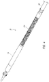
- Figures 4-8 illustrate further views of delivery system 10 with different assemblies translated proximally and described in detail.
- the outer sheath assembly 22 can include an outer proximal shaft 102 directly attached to the handle 14 at its proximal end and an outer hypotube 104 attached at its distal end.
- a capsule 106 can then be attached generally at the distal end of the outer hypotube 104.
- the capsule 106 can be 28 French or less in size.
- the outer proximal shaft 102 may be a tube and is preferably formed of a plastic, but could also be a metal hypotube or other material.
- the outer hypotube 104 can be a metal hypotube which in some embodiments may be cut or have slots, as discussed in detail below.
- the outer hypotube 104 can be covered or encapsulated with a layer of ePTFE, PTFE, or other polymer/material so that the outer surface of the outer hypotube 104 is generally smooth.
- a capsule 106 can be located at a distal end of the outer proximal shaft 102.
- the capsule 106 can be a tube formed of a plastic or metal material.
- the capsule 106 is formed of ePTFE or PTFE.
- this capsule 106 is relatively thick to prevent tearing and to help maintain a self-expanding implant in a compacted configuration.
- the material of the capsule 106 is the same material as the coating on the outer hypotube 104. As shown, the capsule 106 can have a diameter larger than the outer hypotube 104, though in some embodiments the capsule 106 may have a similar diameter as the hypotube 104.
- the capsule 106 may include a larger diameter distal portion and a smaller diameter proximal portion. In some embodiments, there may be a step or a taper between the two portions.
- the capsule 106 can be configured to retain the prosthesis 70 in the compressed position within the capsule 106. Further construction details of the capsule 106 are discussed below.
- the outer sheath assembly 22 is configured to be individually slidable with respect to the other assemblies. Further, the outer sheath assembly 22 can slide distally and proximally relative to the rail assembly 22 together with the mid shaft assembly 21, inner assembly 18, and nose cone assembly 31.
- Figure 5 shows a similar view as Figure 4 , but with the outer sheath assembly 22 removed, thereby exposing the mid shaft assembly 21.
- the mid shaft assembly 21 can include a mid shaft hypotube 43 generally attached at its proximal end to a mid shaft proximal tube 44, which in turn can be attached at its proximal end to the handle 14, and an outer retention ring 42 located at the distal end of the mid shaft hypotube 43.
- the outer retention ring 42 can be attached generally at the distal end of the mid shaft hypotube 43.
- the mid shaft hypotube 43 and/or mid shaft proximal tube 44 can comprise a tube, such as a hypodermic tube or hypotube (not shown).
- the tubes can be made from one of any number of different materials including Nitinol, stainless steel, and medical grade plastics.
- the tubes can be a single piece tube or multiple pieces connected together. Using a tube made of multiple pieces can allow the tube to provide different characteristics along different sections of the tube, such as rigidity and flexibility.
- the mid shaft hypotube 43 can be a metal hypotube which in some embodiments may be cut or have slots as discussed in detail below.
- the mid shaft hypotube 43 can be covered or encapsulated with a layer of ePTFE, PTFE, or other material so that the outer surface of the mid shaft hypotube 43 is generally smooth.
- the outer retention ring 42 can be configured as a prosthesis retention mechanism that can be used to engage with the prosthesis 70 , as discussed with respect to Figure 2A .
- the outer retention ring 42 may be a ring or covering that is configured to radially cover the struts 72 on the prosthesis 70 .
- the outer retention ring 42 can also be considered to be part of the implant retention area 16, and may be at the proximal end of the implant retention area 16.
- the outer retention ring 42 can cover both the prosthesis 70 and the inner retention member 40 to secure the prosthesis 70 on the delivery system 10.
- the prosthesis 70 can be sandwiched between the inner retention member 40 of the inner shaft assembly 18 and the outer retention ring 42 of the mid shaft assembly 21.
- the mid shaft assembly 21 is disposed so as to be individually slidable with respect to the other assemblies. Further, mid shaft assembly 21 can slide distally and proximally relative to the rail assembly 22 together with the outer sheath assembly 22, mid inner assembly 18, and nose cone assembly 31.
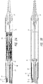
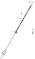
- the rail assembly 20 can include a rail shaft 132 (or rail) generally attached at its proximal end to the handle 14.
- the rail shaft 132 can be made up of a rail proximal shaft 134 directly attached to the handle at a proximal end and a rail hypotube 136 attached to the distal end of the rail proximal shaft 134.
- the rail hypotube 136 can further include an atraumatic rail tip at its distal end.
- the distal end of the rail hypotube 136 can abut a proximal end of the inner retention member 40, as shown in Figure 6 .
- the distal end of the rail hypotube 136 can be spaced away from the inner retention member 40 .
- pull wires which can be used apply forces to the rail hypotube 136 and steer the rail assembly 20.
- the pull wires can extend distally from the knobs in the handle 14, discussed below, to the rail hypotube 136.
- pull wires can be attached at different longitudinal locations on the rail hypotube 136, thus providing for multiple bending locations in the rail hypotube 136, allowing for multidimensional steering.
- a distal pull wire 138 can extend to a distal section of the rail hypotube 136 and two proximal pull wires 140 can extend to a proximal section of the rail hypotube 136, however, other numbers of pull wires can be used, and the particular amount of pull wires is not limiting. For example, a two pull wires can extend to a distal location and a single pull wire can extend to a proximal location.
- ring-like structures attached inside the rail hypotube 136 known as pull wire connectors, can be used as attachment locations for the pull wires, such as proximal ring 137 and distal ring 135.
- the rail assembly 20 can include a distal pull wire connector 135 and a proximal pull wire connector 139.
- the pull wires can directly connect to an inner surface of the rail hypotube 136.
- the distal pull wire 138 can be connected (either on its own or through a connector 135 ) generally at the distal end of the rail hypotube 136.
- the proximal pull wires 140 can connect (either on its own or through a connector 137 ) at a location approximately one quarter, one third, or one half of the length up the rail hypotube 136 from the proximal end.
- the distal pull wire 138 can pass through a small diameter pull wire lumen 139 (e.g., tube, hypotube, cylinder) attached on the inside of the rail hypotube 136. This can prevent the wires 138 from pulling on the rail hypotube 136 at a location proximal to the distal connection.
- the lumen 139 can act as compression coils to strengthen the proximal portion of the rail hypotube 136 and prevent unwanted bending.
- the lumen 139 is only located on the proximal half of the rail hypotube 136.
- multiple lumens 139 such as spaced longitudinally apart or adjacent, can be used per distal wire 139.
- a single lumen 139 is used per distal wire 139.
- the lumen 139 can extend into the distal half of the rail hypotube 136.
- the lumen 139 is attached on an outer surface of the rail hypotube 136. In some embodiments, the lumen 139 is not used.
- the wires can be spaced approximately 180° from one another to allow for steering in both directions.
- the wires can be spaced approximately 180° from one another to allow for steering in both directions.
- the pair of distal pull wires 138 and the pair of proximal pull wires 140 can be spaced approximately 90° from each other.
- the pair of distal pull wires 138 and the pair of proximal pull wires 140 can be spaced approximately 0° from each other.
- other locations for the pull wires can be used as well, and the particular location of the pull wires is not limiting.
- the distal pull wire 138 can pass through a lumen 139 attached within the lumen of the rail hypotube 136. This can prevent an axial force on the distal pull wire 138 from creating a bend in a proximal section of the rail hypotube 136.
- the rail assembly 20 is disposed so as to be slidable over the inner shaft assembly 18 and the nose cone assembly 31.
- the outer sheath assembly 22, the mid shaft assembly 21, the inner shaft assembly 22, and the nose cone assembly 31 can be configured to slide together along or relative to the rail assembly 20, such as proximally and distally with or without any bending of the rail assembly 20.
- the outer sheath assembly 22, the mid shaft assembly 21, the inner shaft assembly 22, and the nose cone assembly 31 can be configured to retain the implant 70 in a compressed position when they are simultaneously slid along or relative to the rail assembly 20 .
- Figure 7 shows approximately the same view as Figure 6A , but with the rail assembly 20 removed, thereby exposing the inner shaft assembly 18.
- the inner shaft assembly 18 can include an inner shaft 122 generally attached at its proximal end to the handle 14, and an inner retention ring 40 located at the distal end of the inner shaft 122.
- the inner shaft 122 itself can be made up of an inner proximal shaft 124 directly attached to the handle 14 at a proximal end and a distal section 126 attached to the distal end of the inner proximal shaft 124.
- the inner retention ring 40 can be attached generally at the distal end of the distal section 126.
- the inner proximal shaft 124 can comprise a tube, such as a hypodermic tube or hypotube (not shown).
- the tube can be made from one of any number of different materials including Nitinol, cobalt chromium, stainless steel, and medical grade plastics.
- the tube can be a single piece tube or multiple pieces connected together. A tube comprising multiple pieces can provide different characteristics along different sections of the tube, such as rigidity and flexibility.
- the distal section 126 can be a metal hypotube which in some embodiments may be cut or have slots as discussed in detail below.
- the distal section 126 can be covered or encapsulated with a layer of ePTFE, PTFE, or other material so that the outer surface of the distal section 126 is generally smooth.
- the inner retention member 40 can be configured as a prosthesis retention mechanism that can be used to engage with the prosthesis 70 , as discussed with respect to Figure 2A .
- the inner retention member 40 may be a ring and can include a plurality of slots configured to engage with struts 72 on the prosthesis 70 .
- the inner retention member 40 can also be considered to be part of the implant retention area 16, and may be at the proximal end of the implant retention area 16.
- the outer retention ring 42 can cover both the prosthesis and the inner retention member 40 to secure the prosthesis on the delivery system 10.
- the prosthesis 70 can be sandwiched between the inner retention member 40 of the inner shaft assembly 18 and the outer retention ring 42 of the mid shaft assembly 21.
- the inner shaft assembly 18 is disposed so as to be individually slidable with respect to the other assemblies. Further, the inner assembly 18 can slide distally and proximally relative to the rail assembly 22 together with the outer sheath assembly 22, mid shaft assembly 21, and nose cone assembly 31.
- the nose cone assembly 31 Moving further inwardly from the inner shaft assembly 18 is the nose cone assembly 31 also seen in Figure 8 .
- This may be a nose cone shaft 27, and in some embodiments, may have a nose cone 28 on its distal end.
- the nose cone 28 can be made of polyurethane for atraumatic entry and to minimize injury to venous vasculature.
- the nose cone 28 can also be radiopaque to provide for visibility under fluoroscopy.
- the nose cone shaft 27 may include a lumen sized and configured to slidably accommodate a guide wire so that the delivery system 10 can be advanced over the guide wire through the vasculature.
- a guide wire may not use a guide wire and thus the nose cone shaft 27 can be solid.
- the nose cone shaft 27 may be connected from the nose cone 28 to the handle, or may be formed of different segments such as the other assemblies. Further, the nose cone shaft 27 can be formed of different materials, such as plastic or metal, similar to those described in detail above.
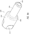
- the nose cone shaft 27 includes a guide wire shield 1200 located on a portion of the nose cone shaft 27. Examples of such a guide wire shield can be found in Figures 9A-B .
- the guide wire shield 1200 can be proximal to the nose cone 28.
- the guide wire shield 1200 can be translatable along the nose cone shaft 27.
- the guide wire shield 1200 can be locked in place along the nose cone shaft 27.
- the guide wire shield 1200 can be at least partially located within the nose cone 28.
- the guide wire shield 1200 can allow for smooth tracking of the guide wire with the implant 70 loaded, and can provide a large axial diameter landing zone for a distal end of the implant so that the distal end of the implant 70 may spread out properly and be arranged in a uniform radial arrangement. This uniformity allows for proper expansion. Furthermore, the guide wire shield 1200 can prevent kinking or damaging of the nose cone shaft 27 during compression/crimping of the prosthesis 70, which can exert a large compressive force on the nose cone shaft 27. As the prosthesis 70 can be crimped onto the guide wire shield 1200 instead of directly on the nose cone shaft 27, the guide wire shield 1200 can provide a protective surface.
- the guide wire shield 1200 can include a lumen 1202 configured to surround the nose cone shaft 27.
- the guide wire shield 1200 can include a larger diameter distal end 1204 and a smaller diameter proximal end 1206.
- the dimension change between the two ends can be tapered, or can be a step 1208 such as shown in Figure 9A .
- the distal end 1204 can include a number of indents 1210 for easier gripping by a user, but may not be included in all embodiments.
- the proximal end 1206 and the distal end 1204 can both be generally cylindrical, but the particular shape of the guide wire shield 1200 is not limiting.
- the distal end of the prosthesis 70 can be crimped so that it is radially in contact with the proximal end 1206 of the guide wire shield 1200. This can allow the prosthesis 70 to be properly spread out around an outer circumference of the proximal end 1206 of the guide wire shield 1200. In some embodiments, the distal end of the prosthesis 70 can longitudinally abut against the proximal end of the distal end 1204 (e.g., at the step 1208 ), thus providing a longitudinal stop.
- Figure 9B shows an alternate embodiment of a guide wire shield 1200' having a more tapered configuration.
- the proximal end 1206' of the guide wire shield 1200' can be a single radially outward taper 1208' to the distal end 1204' of the guide wire shield 1200', which can be generally cylindrical.
- the guide wire shield 1200' can also include a lumen 1202' for receiving the nose cone shaft 27.
- the nose cone assembly 31 is disposed so as to be individually slidable with respect to the other assemblies. Further, the nose cone assembly 31 can slide distally and proximally relative to the rail assembly 22 together with the outer sheath assembly 22, mid shaft assembly 21, and inner assembly 18.
- one or more spacer sleeves can be used between different assemblies of the delivery system 10.
- a spacer sleeve can be located concentrically between the mid shaft assembly and the rail assembly 20 , generally between the mid 43 and rail hypotubes 136.
- the spacer sleeve can be generally embedded in the hypotube 43 of the mid shaft assembly 21, such as on an inner surface of the mid shaft assembly 21.
- a spacer sleeve can be located concentrically between the rail assembly 20 and the inner assembly 18, generally within the rail hypotube 136.
- a spacer sleeve can be used between the outer sheath assembly 22 and the mid shaft assembly 21.
- a spacer sleeve can be used between the inner assembly 18 and the nose cone assembly 31.
- 4, 3, 2, or 1 of the above-mentioned spacer sleeves can be used.
- the spacer sleeves can be used in any of the above positions.
- the spacer sleeve can be made of a polymer material such as braided Pebax ® and can be lined, for example with PTFE, on the inner diameter, though the particular material is not limiting.
- the spacer sleeve can advantageously reduce friction between the steerable rail assembly 20 and its surrounding assemblies.
- the spacer sleeves can act as a buffer between the rail assembly 20 and the inner/nose cone assembly 18/30.
- the spacer sleeve can take up any gap in radius between the assemblies, preventing compressing or snaking of the assemblies during steering.
- the spacer sleeve may include cuts or slots to facilitate bending of the spacer sleeve.
- the spacer sleeve may not include any slots, and may be a smooth cylindrical feature.
- the spacer sleeve can be mechanically contained by the other lumens and components, and is thus not physically attached to any of the other components, allowing the spacer sleeve to be "floating" in that area.
- the floating aspect of the spacer sleeve allows it to move where needed during deflection and provide a support and/or lubricious bear surface/surfaces. Accordingly, the floating aspect allows the delivery system 10 to maintain flex forces.
- the spacer sleeve can be connected to other components.
- the outer sheath assembly 22, the mid shaft assembly 21, the inner assembly 18, and the rail assembly 20 can contain an outer hypotube 104, a mid shaft hypotube, a distal section 126, and a rail hypotube 136, respectively.
- Each of these hypotubes/sections/shafts can be laser cut to include a number of slots, thereby creating a bending pathway for the delivery system to follow. While different slot assemblies are discussed below, it will be understood that any of the hypotubes can have any of the slot configurations discussed below.
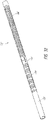
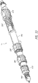
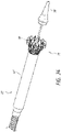
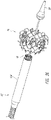
- Figures 10-14 show the different hypotubes in isolated format.
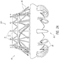
- the outer hypotube 104 can be generally formed of a metal coil or a plurality of metal coils.
- the outer hypotube 104 can be formed of a proximal metal coil 107 and a distal metal coil 108.
- the proximal metal coil 107 and the distal metal coil 108 can be longitudinally separated by a tube portion 110, such as shown in Figure 10 .
- the proximal metal coil 107 and the distal metal coil 108 connect.
- the proximal metal coil 107 and the distal metal coil 108 can be connected to an outer surface of the tube portion 110, for example at the distal end of the proximal metal coil 107 and a proximal end of the distal metal coil 108, in order to form the full outer hypotube 104.
- the proximal metal coil 107 and the distal metal coil 108 are generally the same.
- the proximal metal coil 107 and the distal metal coil 110 are different, for example in spacing between coils, curvature, diameter, etc.
- the distal metal coil 108 has a larger diameter than the proximal metal coil 107, such as when the distal metal coil 108 forms the large diameter of the capsule 106.
- the metal coils 108/107 can form the capsule 106.
- the coils can be coated by polymer layers, such as described in detail below regarding the capsule construction.
- the coil construction can allow the outer hypotube 104 to follow the rail in any desired direction.
- Figures 11-12B shows that the mid shaft hypotube 43 can be a metal laser cut hypotube, such as a lasercut Nitinol hypotube.
- Figure 12A illustrates a flat pattern of Figure 11 .
- the hypotube 43 can have a number of slots/apertures cut into the hypotube.
- the cut pattern can be the same throughout.
- the mid shaft hypotube 43 can have different sections having different cut patterns.
- the proximal end of the mid shaft hypotube 43 can be a first section 210 having a plurality circumferentially extending slot pairs 213 spaced longitudinally along the first section 211.
- the slot pairs 213 can be composed of a first thin slot 217.
- a second slot 221 of each of the slot pairs 213 can be thicker than the first slot 217, such as 1, 2, 3, 4, or 5 times thicker.
- the second slot 217 can be generally the same longitudinal thickness throughout the slot.
- Each of the slots of the slot pair 213 can end in a teardrop shape 219 in some embodiments to facilitate bending.
- the mid shaft hypotube 43 can include a second section 220 having a number of slot pairs 222. Similar to the first section 211, the second section 220 can have a plurality of circumferentially extending slots spaced longitudinally along the second section 220 . Generally, two slots (e.g., one slot pair 222 ) are cut around each circumferential location, forming almost half of a circumference. Accordingly, "backbones" 224 can be formed between the slots extending up the length of the second section 220 .
- Each slot pair 222 can include a first slot 226 that is generally thin and has no particular shape (e.g., it can look the same as the slots 213 in the first section 211 ), and a second slot 228 that is significantly longitudinally thicker than the first slot 226.
- the second slot 228 can be narrower at its ends and longitudinally thicker in its middle portion, thereby forming a curved slot.
- each slot pair 222 can be offset approximately 45 or 90 degrees as compared to longitudinally adjacent slot pairs 222.
- a second slot pair 222 is offset 90 degrees from an adjacent first slot pair 222, and a third slot pair 222 adjacent the second slot pair 222 can have the same configuration of the first slot pair 222.
- This repeating pattern can extend along a length of the second section 220 , thereby providing a particular bending direction induced by the second slot 228 of the slot pairs 222. Accordingly, the "backbone" 224 shifts circumferential position due to the offsetting of adjacent shifting slot pairs 222.
- Each of the slots of the slot pair 222 can end in a teardrop shape 229 in some embodiments to facilitate bending.
- the mid shaft hypotube 43 can have a third section 230 having a number of slots.
- the outer retention ring 240 can be attached to a distal end of the third section 230 .
- the third section 230 can have circumferentially extending slot pairs 232, each slot on the slot pair extending about half way along the circumference to form the two backbones 234.
- the slot pairs 232 can be composed of a first thin slot 236, similar to the slots 213 discussed in the first section 211.
- a second slot 238 of each of the slot pairs 232 can be thicker than the first slot 236, such as 1, 2, 3, 4, or 5 times thicker.
- the second slot 238 can be generally the same longitudinal thickness throughout the slot, unlike the second slot 228 of the second section 220 .
- the first slots 236 and the second slots 238 can be circumferentially aligned along a length of the third section 230 so that all of the first slots 236 are in the same circumferential position and all of the second slots 238 are in the same circumferential position.
- the second slots 238 can be aligned with one of the circumferential positions of the second slots 228 of the second section 220 .
- Each of the slots of the slot pair 232 can end in a teardrop shape 239 in some embodiments to facilitate bending.
- an outer retention ring strengthener 240 which can partially or fully circumferentially surround the outer retention member 40 can have a number of slots/holes/apertures as well, such as shown in Figures 11-12 . This can allow it to bend over curves, especially tight curves.
- the distal end of the strengthener 240 includes a number of generally circular/elliptical holes 242. This can last for approximately half of the length of the strengthener 240.
- one circumferential half of the strengthener 240 can include repeating thin slots 244 spaced by elongate ovoid holes 246. For example, two circumferentially spaced apart elongate ovoid holes 246 can be between each thin slot 244.
- Each of the slots 244 can end in a teardrop shape 249 in some embodiments to facilitate bending.
- the strengthener 240 can include a number of large slots 248, for example 1, 2, 3, 4, or 5 large slots 248 spaced longitudinally apart.
- the large slots 248 can be larger in the middle and narrow towards each circumferential end.
- the large slots 248 may include ending expansions 247 to facilitate flexibility.
- the outer retention strengthener 240 can provide strength to lower deployment forces, protect the prosthesis 70 from any metal layers, and can add strength.
- the liner can 240 be a polymer, such as PTFE, though the type of polymer or material is not limiting.
- the strengthener 240 can be a metal.
- the strengthener 240 can further include an outer polymer layer/jacket, such as a Pebax ® jacket. This prevents the strengthener 240 from catching on the outer sheath assembly 22.
- the outer retention ring 42 can further include an inner liner for smoothly transitioning over the prosthesis 70 .
- the inner liner can be PTFE or etched PTFE, though the particular material is not limiting and other reduced friction polymers can be used.
- the liner 251 may not be flush at the distal end of the outer retention ring 42. Instead, the liner 251 can be extended and inverted at the distal end in order to cover the distal end of the outer retention ring 42. In some embodiments, the liner 251 can cover an outer surface of the strengthener 240 as well. This can create a seamless rolled reinforced tip of the liner 251.
- the liner 251 can fully or partially cover an outer surface of the outer retention ring 42, for example 1/4, 1/3, 1/2, 2/3, 3/4 (or greater than 1/4, 1/3, 1/2, 3 ⁇ 4), or all of the outer retention ring 42.
- This solution is advantageous over previously known methods, such as disclosed in U.S. Pat. No. 6,622,367 , as PTFE lined applications do not adhere particularly well to reinforcements or the outer jacket.
- Delamination is a serious concern because the delaminated liner can tear and embolize during deployment, and the delaminated layer can cause extremely high loading and deployment forces. Delaminated layers can also cause lumen translation problems by locking up shafts thereby adding translational force requirements.
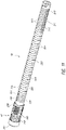
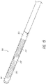
- Figure 13 shows an embodiment of the rail hypotube 136 (distal end towards the right).
- the rail hypotube 136 can also contain a number of circumferential slots.
- the rail hypotube 136 can generally be broken into a number of different sections. At the most proximal end is an uncut (or unslotted) hypotube section 231. Moving distally, the next section is the proximal slotted hypotube section 133. This section includes a number of circumferential slots cut into the rail hypotube 136. Generally, two slots are cut around each circumferential location forming almost half of the circumference. Accordingly, two backbones are formed between the slots extending up the length of the hypotube 136.
- section that can be guided by the proximal pull wires 140. Moving further distally is the location 237 where the proximal pull wires 140 connect, and thus slots can be avoided. Thus section is just distal of the proximally slotted section.
- distal slotted hypotube section 235 Distally following the proximal pull wire connection area is the distal slotted hypotube section 235.
- This section is similar to the proximal slotted hypotube section 233, but has significantly more slots cut out in an equivalent length.
- the distally slotted hypotube section 235 provides easier bending than the proximally slotted hypotube section 233.
- the proximal slotted section 233 can be configured to experience a bend of approximately 90 degrees with a half inch radius whereas the distal slotted section 135 can bend at approximately 180 degrees within a half inch.
- the spines of the distally slotted hypotube section 235 are offset from the spines of the proximally slotted hypotube section 233.
- the two sections will achieve different bend patterns, allowing for three-dimensional steering of the rail assembly 20 .
- the spines can be offset 30, 45, or 90 degrees, though the particular offset is not limiting.
- the proximally slotted hypotube section 233 can include compression coils. This allows for the proximally slotted hypotube section 233 to retain rigidity for specific bending of the distally slotted hypotube section 235.
- distal pull wire connection area 241 which is again a non-slotted section of the rail hypotube 136.
- the inner assembly 18 is composed generally of two sections.
- the proximal section is a hypotube 129, either slotted or non-slotted.
- the distal section 126 which at least partially overlaps an outer surface of the proximal hypotube 129, can be designed to be particularly flexible.
- the distal section 126 can be more flexible than any of the other shafts discussed herein.
- the distal section 126 can be more flexible than any shaft discussed herein other than the nose cone shaft 27.
- the distal section 126 can be a flexible tube or hypotube.
- the distal section 126 can be a cable, such as a flexible cable.
- the cable can several strands of wire, such as metal, plastic, polymer, ceramic, etc., wound together to form a rope or cable. Because the cable is so flexible, it can more easily bend with the rail assembly 20. Further, the cable can be smooth, which allows the rail assembly 20 to track over a smooth surface, eliminating the need for any inner liner on the rail assembly 20 .
- the capsule 106 can be formed from one or more materials, such as PTFE, ePTFE, polyether block amide (Pebax ® ), polyetherimide (Ultem ® ), PEEK, urethane, Nitinol, stainless steel, and/or any other biocompatible material.
- the capsule is preferably compliant and flexible while still maintaining a sufficient degree of radial strength to maintain a replacement valve within the capsule 106 without substantial radial deformation, which could increase friction between the capsule 106 and a replacement valve 70 contained therein.
- the capsule 106 also preferably has sufficient column strength to resist buckling of the capsule, and sufficient tear resistance to reduce or eliminate the possibility of replacement valve tearing and/or damaging the capsule 106.
- Flexibility of the capsule 106 can be advantageous, particularly for a transseptal approach.
- the capsule 106 can flex to follow the curved member without applying significant forces upon the curved member, which may cause the curved member to decrease in radius. More specifically, the capsule 106 can bend and/or kink as it is being retracted along such a curved member such that the radius of the curved member is substantially unaffected.
- Figure 15 shows embodiments of a capsule 106 that can be used with embodiments of the delivery system 10.
- the capsule 106 may include any of the materials and properties discussed above. With many implant capsules, compression resistance and flexibility are typically balanced together, as improved flexibility can lead to worse compression resistance. Thus, there tends to be a choice made between compression resistance and flexibility. However, disclosed are embodiments of a capsule 106 that can achieve both high compression resistance as well as high flexibility. Specifically, the capsule 106 can bend in multiple directions.
- a metal hypotube can provide radial strength and compression resistance, while specific slots/cuts in the hypotube can enable the flexibility of the capsule 106.
- a thin liner and a jacket can surround the capsule 106, such as a polymer layer, to prevent any negative interactions between the implant 70 and the capsule 106.
- the capsule 106 can have a particular construction to allow for it to achieve advantageous properties, as shown in Figure 15 .
- the capsule 106 can be made of several different layers to provide such properties.
- the capsule 106 can be formed of a metal layer 402 , which gives the capsule 106 its structure.
- This metal layer can include the coils discussed with respect to Figure 10 , or could be one or more hypotubes.
- the capsule 106 is then covered on an outer surface by a polymer layer and on an inner surface by a liner. All of these features are discussed in detail below.
- the metal layer 404 can be, for example, a metal hypotube or laser cut hypotube.
- the metal layer 404 can be a metal coil or helix, as discussed in detail above with respect to Figure 10 .
- the metal layer 404 can have a thickness of 0.18 mm (0.007 inches) or about 0.18 mm (or about 0.007 inches).
- the coil dimensions can stay the same throughout a length of the metal layer 404 .
- the coil dimensions can vary along a length of the metal layer 404 .
- the coils can vary between coils having a 0.36 mm (0.014-inch ) gap with a 0.53 mm (0.021-inch ) pitch (e.g., small coils), coils having a 0.51 mm (0.020 inch) gap with a 0.51 mm (0.02-inch) pitch (e.g., large coils), and coils having a 0.51 mm (0.020-inch) gap with a 0.69 mm (0.027-inch) pitch (e.g., spaced large coils).
- these particular dimensions are merely examples, and other designs can be used as well.
- the distalmost end of the metal layer 404 can be formed out of the small coils. Moving proximally, the metal layer 404 may then transition to a section of large coils, followed again by a section of small coils, and then finally the proximalmost section can be the spaced large coils. As an example set of lengths, though not limiting, the distalmost small coil section may have a length of 10 mm (or about 10 mm). Moving proximally, the adjacent large coil section may extend 40 mm (or about 40 mm) to 60 mm (or about 60 mm) in length. These two sections would be found in the distal metal coil 108 shown in Figure 10 .
- the small coil section can have a length of 10 mm (or about 10 mm).
- the remaining portion of the proximal metal coil 107 can be the spaced large coil section.
- the spaced large coil section can have a length of 40 mm (or about 40 mm) to 60 mm (or about 60 mm) or greater.
- the metal layer 404 can be covered by an outer polymer layer or jacket 402.
- the outer polymer 402 layer is an elastomer, though the particular material is not limiting.
- the outer polymer layer 402 can comprise polytetrafluoroethylene (PTFE) or expanded polytetrafluoroethylene (ePTFE).
- PTFE polytetrafluoroethylene
- ePTFE expanded polytetrafluoroethylene
- the ePTFE can have very different mechanical properties that PTFE.
- ePTFE can be much more flexible while still maintaining good tensile/elongation properties.
- the outer polymer layer 402 can comprise a thermoplastic elastomer, such as PEBAX ® .
- the outer polymer layer 402 can be pre-axially stressed before applying to the capsule.
- the outer polymer layer 402 can be approximately 0.15 to 0.20 mm ( 0.006 to 0.008 inches) in thickness, but the particular thickness is not limiting.
- the outer polymer layer 402 can be applied to the metal layer 404 to form an outer jacket, such as by reflowing the polymer.
- the outer polymer layer 402 can be directly applied to the metal layer 404 .
- an adhesive layer 406 can be disposed between the metal layer 404 and the outer polymer layer 402 to promote attachment of the outer polymer layer to the metal layer.
- a fluoropolymer, or other soft durometer fluoroelastomer can be applied between the metal layer 404 and the outer layer 402 in order to attach the two layers together and prevent delamination.
- the adhesive layer 406 is not used.
- FEP fluorinated ethylene propylene
- other materials can be included between the metal layer 404 and the outer polymer layer 402 in order to improve properties.
- fluorinated ethylene propylene (FEP) sections 408 can improve radial strength, in particular when the implant is under compression. While an FEP layer 408 is discussed as a particular material, other high strength polymers, metals, or ceramics can be used as well, and the particular material is not limiting.
- the FEP layer 408 can also act as an adhesive in some instances.
- FEP sections 408 can be included at the distal and proximal ends of the capsule 106.
- the FEP sections 408 can either overlap the adhesive layer 406.
- FEP sections 408 can be located between the adhesive layer 406 and the metal layer 404 or between the adhesive layer 406 and the outer polymer layer 402 .
- the FEP sections 408 may be located in sections of the capsule 106 that do not include an adhesive layer 406 .
- the FEP section 408 located at the distal end of the capsule 106 can have a length of 10 mm (or about 10 mm), thought he particular length is not limiting. In some embodiments, the FEP section 408 is approximately 0.003 inches in thickness, but the thickness may vary and is not limited by this disclosure. In some embodiments, different FEP sections 408 (e.g., a proximal section and a distal section) can have different thicknesses. In some embodiments, all FEP 408 layers have the same thickness. Example thicknesses can be 0.15 mm or 0.075 mm (0.006 inches or 0.003 inches).
- a liner 410 can be included on its radially inner surface.
- the liner 410 can be formed of a low friction and/or high lubricity material that allows for the capsule 106 to be translated over the prosthesis 70 without catching or damaging portions of the prosthesis 70 .
- the liner 410 can be PTFE, which can resist radial expansion and decrease friction with the prosthesis 70 .
- the liner 410 is made from ePTFE.
- the ePTFE liner layer 410 can be pre-compressed before applying onto the inner layer of the capsule 106.
- portions of the outer polymer layer 402 and the liner 410 can be in contact with one another.
- the ePTFE liner 410 and/or outer polymer layer 402 can be axially compressed. Then, the layers can be bonded together with reflow techniques during manufacturing.
- the ePTFE liner 410 can be axially compressed, such as over a mandrel, while the outer polymer layer 402 can be placed over it. These two layers can then be reflowed (e.g., melting under pressure) to connect. The combined layers can be slid into and/or around the metal layer 404 discussed herein, and can be melted under pressure again to form the final capsule 106. This technique can allow for the capsule 106 to maintain flexibility and prevent breakage/tearing.
- the inner liner 410 can be ePTFE in some embodiments.
- the surface friction of ePTFE can be about 15% less than standard PTFE, and can be about 40% less than standard extruded thermoplastics that are used in the art.
- the liner layer 410 can extend only along an inner surface of the capsule 106 and terminate at a distal end. However, to prevent delamination during loading of the implant 70 , the liner 410 may not be flush at the distal end of the capsule 106. Instead, the liner 410 can be extended and inverted at the distal end in order to cover the distal end of the capsule 106 as well as an outer diameter of a portion of the outer polymer layer 402 . This can create a seamless rolled reinforced tip of the liner 410. This solution is advantageous over previously known methods, such as disclosed in U.S. Pat. No. 6,622,367 , as PTFE lined applications do not adhere particularly well to reinforcements or the outer jacket.
- another FEP section 412 can be included between the liner 410 and the metal layer 404 .
- the FEP section 412 can be located on distal metal coil 108, as well as the tube 110 transitioning between the distal metal coil 108 and the proximal metal coil 107. In some embodiments, the FEP section 412 may continue partially or fully into the proximal metal coil 107.
- an FEP section 412 can be included in the proximalmost portion of the proximal metal coil 107. This FEP section 412 be approximately 0.5 inches in length. In some embodiments, there is a longitudinal gap between the proximalmost FEP section 412 and the FEP section 412 that extends over the distal metal coil 108. In some embodiments, the previously mentioned FEP sections 412 are continuous.
- the metal layer 404 may stop proximal to the edges of the outer polymer layer 402 , liner 410, and FEP section 412. If so, a thicker portion of an adhesive layer 409 can be applied at the distal end of the metal layer 404 to match the distal end of the other layers. However, this section can be removed during manufacture, so the distal end of the metal layer 404 is the distal end of the capsule 106, which can then be covered by the liner 410. In some embodiments, the extended sections distal to the metal layer 404 are not used.
- the handle 14 is located at the proximal end of the delivery system 10 and is shown in Figure 16 .
- a cross-section of the handle 14 is shown in Figure 17 .
- the handle 14 can include a number of actuators, such as rotatable knobs, that can manipulate different components of the delivery system 10. The operation of the handle 10 is described with reference to delivery of a replacement mitral valve prosthesis 70, though the handle 10 and delivery system 10 can be used to deliver other devices as well.
- the handle 14 is generally composed of two housings, a rail housing 202 and a delivery housing 204 , the rail housing 202 being circumferentially disposed around the delivery housing 204 .
- the inner surface of the rail housing 202 can include a screwable section configured to mate with an outer surface of the delivery housing 204 .
- the delivery housing 204 is configured to slide (e.g., screw) within the rail housing 202 , as detailed below.
- the rail housing 202 generally surrounds about one half the length of the delivery housing 204 , and thus the delivery housing 204 extends both proximally and distally outside of the rail housing 202.
- the rail housing 202 can contain two rotatable knobs, a distal pull wire knob 206 and a proximal pull wire knob 208. However, the number of rotatable knobs on the rail housing 202 can vary depending on the number of pull wires used. Rotation of the distal pull wire knob 206 can provide a proximal force, thereby providing axial tension on the distal pull wires 138 and causing the distal slotted section 135 of the rail hypotube 136 to bend. The distal pull wire knob 206 can be rotated in either direction, allowing for bending in either direction, which can control anterior-posterior angles.
- Rotation of the proximal pull wire knob 208 can provide a proximal force, and thus axial tension, on the proximal pull wires 140, thereby causing the proximal slotted section 133 of the rail hypotube 136 to bend, which can control the medial-lateral angle.
- the proximal pull wire knob 108 can be rotated in either direction, allowing for bending in either direction.
- both knobs are actuated, there can be two bends in the rail hypotube 136, thereby allowing for three-dimensional steering of the rail shaft 132, and thus the distal end of the delivery system 10.
- the proximal end of the rail shaft 132 is connected on an internal surface of the rail housing 202 .
- the bending of the rail shaft 132 can be used to position the system, in particular the distal end, at the desired patient location, such as at the native mitral valve.
- rotation of the pull wire knobs 206/208 can help steer the distal end of the delivery system 10 through the septum and left atrium and into the left ventricle so that the prosthesis 70 is located at the native mitral valve.
- the proximal ends of the inner shaft assembly 19, outer sheath assembly 22, mid shaft assembly 21, and nose cone shaft assembly 30 can be connected to an inner surface of the delivery housing 204 of the handle 14. Thus, they can move axially relative to the rail assembly 20 and rail housing 202 .
- a rotatable outer sheath knob 210 can be located on the distal end of the delivery housing 204 , being distal to the rail housing 202. Rotation of the outer sheath knob 210 will pull the outer sheath assembly 22 in an axial direction proximally, thus pulling the capsule 106 away from the implant 70 and releasing the distal end 301 of implant 70 . Thus the outer sheath assembly 22 is individually translated with respect to the other shafts in the delivery system 10. The distal end 303 of the implant 70 can be released first, while the proximal end 301 of the implant 70 can remain radially compressed between the inner retention member 40 and the outer retention member 42.
- a rotatable mid shaft knob 214 can be located on the delivery housing 204 , in some embodiments proximal to the rotatable outer sheath knob 210, being distal to the rail housing 202 .
- Rotation of the mid shaft knob 212 will pull the mid shaft assembly 21 in an axial direction proximally, thus pulling the outer retention ring 42 away from the implant 70 and uncovering the inner retention member 40 and the proximal end 301 of the implant 70 , thereby releasing the implant 70 .
- the mid shaft assembly 21 is individually translated with respect to the other shafts in the delivery system 10.
- a rotatable depth knob 212 Located on the proximal end of the delivery housing 204 , and thus proximal to the rail housing 202 , can be a rotatable depth knob 212. As the depth knob 212 is rotated, the entirety of the delivery housing 204 moves distally or proximally with respect to the rail housing 202 which will remain in the same location. Thus, at the distal end of the delivery system 10, the inner shaft assembly 18, outer sheath assembly 22, mid shaft assembly 21, and nose cone shaft assembly 31 together (e.g., simultaneously) move proximally or distally with respect to the rail assembly 20 while the implant 70 remains in the compressed configuration.
- actuation of the depth knob 212 can sequentially move the inner shaft assembly 18, outer sheath assembly 22, mid shaft assembly 21, and nose cone shaft assembly 31 relative to the rail assembly 20. In some embodiments, actuation of the depth knob 212 can together move the inner shaft assembly 18, outer sheath assembly 22, and mid shaft assembly 21 relative to the rail assembly 20. Accordingly, the rail shaft 132 can be aligned at a particular direction, and the other assemblies can move distally or proximally with respect to the rail shaft 132 for final positioning while not releasing the implant 70 .
- the components can be advanced approximately 1, 2, 3, 5, 6, 7, 8, 9, or 10 cm along the rail shaft 132.
- the components can be advanced more than approximately 1, 2, 3, 5, 6, 7, 8, 9, or 10 cm along the rail shaft 132.
- FIG. 2C An example of this is shown in Figure 2C .
- the capsule 106 and outer retention ring 42 can then be individually withdrawn with respect to the inner assembly 18 as discussed above, in some embodiments sequentially, releasing the implant 70.
- the assemblies other than the rail assembly 20 can then be withdrawn back over the rail shaft 132 by rotating the depth knob 212 in the opposite direction.
- the handle 14 can further include a mechanism (knob, button, handle) 216 for moving the nose cone shaft 27, and thus the nose cone 28.
- a knob 216 can be a portion of the nose cone assembly 31 that extends from a proximal end of the handle 14.
- a user can pull or push on the knob 216 to translate the nose cone shaft 27 distally or proximally individually with respect to the other shafts. This can be advantageous for proximally translating the nose cone 28 into the outer sheath assembly 22 /capsule 106, thus facilitating withdraw of the delivery system 10 from the patient.
- the handle 14 can provide a lock 218, such as a spring lock, for preventing translation of the nose cone shaft 27 by the knob 216 discussed above.
- the lock 218 can be always active, and thus the nose cone shaft 27 will not move without a user disengaging the lock 218.
- the lock can be, for example, a spring lock that is always engaged until a button 218 on the handle 14 is pressed, thereby releasing the spring lock and allowing the nose cone shaft 27 to translate proximally/distally.
- the spring lock 218 allows one-way motion, either proximal or distal motion, of the nose cone shaft 27 but prevents motion in the opposite direction.
- the handle 14 can further include a communicative flush port for flushing out different lumens of the delivery system 10.
- a single flush port on the handle 14 can provide fluid connection to multiple assemblies.
- the flush port can provide fluid connection to the outer sheath assembly 22.
- the flush port can provide fluid connection to the outer sheath assembly 22 and the mid shaft assembly 21.
- the flush port can provide fluid connection to the outer sheath assembly 22, the mid shaft assembly 21, and the rail assembly 20 .
- the flush port can provide fluid connection to the outer sheath assembly 22, the mid shaft assembly 21, the rail assembly 20 , and the inner assembly 18.
- the rail shaft 132, the outer retention ring 42, and the capsule 406 can all be flushed by a single flush port.
- the delivery system 10 can be used in a method for percutaneous delivery of a replacement mitral valve to treat patients with moderate to severe mitral regurgitation.
- the below methods are merely examples of the how the delivery system may be used. It will be understood that the delivery systems described herein can be used as part of other methods as well.
- the delivery system 10 can be placed in the ipsilateral femoral vein 1074 and advanced toward the right atrium 1076. A transseptal puncture using known techniques can then be performed to obtain access to the left atrium 1078. The delivery system 10 can then be advanced in to the left atrium 1078 and then to the left ventricle 1080. Figure 18 shows the delivery system 10 extending from the ipsilateral femoral vein 1074 to the left atrium 1078.
- a guide wire is not necessary to position the delivery system 10 in the proper position, although in other embodiments, one or more guide wires may be used.
- a user can be able to steer the delivery system 10 through the complex areas of the heart in order to position a replacement mitral valve in line with the native mitral valve.
- This task can be performed with or without the use of a guide wire with the above disclosed system.
- the distal end of the delivery system can be advanced into the left atrium 1078.
- a user can then manipulate the rail assembly 20 to target the distal end of the delivery system 10 to the appropriate area.
- a user can then continue to pass the bent delivery system 10 through the transseptal puncture and into the left atrium 1078.
- a user can then further manipulate the delivery system 10 to create an even greater bend in the rail assembly 20 .
- a user can torque the entire delivery system 10 to further manipulate and control the position of the delivery system 10.
- a user can then place the replacement mitral valve in the proper location.
- This can advantageously allow delivery of a replacement valve to an in-situ implantation site, such as a native mitral valve, via a wider variety of approaches, such as a transseptal approach.
- the rail assembly 20 can be particularly advantageous for entering into the native mitral valve.
- the rail assembly 20 can form two bends, both of which can be located in the left atrium 1078.
- the bends in the rail assembly 20 can position the prosthesis 70 , located in the implant retention area 16, so that it is coaxial with the native mitral valve.
- the outer sheath assembly 22, mid shaft assembly 21, inner assembly 18, and nose cone assembly 31 can together be advanced (e.g., using the depth knob 212 of the handle 14 ) distally relative to the rail assembly 20 .
- These assemblies advance straight off of the rail assembly 20 , thus advancing them coaxial with the native mitral valve until the prosthesis 70 is to be released while maintain the prosthesis 70 in the compressed configuration, as discussed below.
- the rail assembly 20 provides the ability for a user to lock the angular position in place, so that the user then has to just longitudinally advance the other assemblies over the rail assembly 20 while not needed to make any angular changes, greatly simplifying the procedure.
- the rail assembly 20 acts as an independent steering assembly, where all the assembly does is provide steerability and no further prosthesis release functionality. Further, the construction of the rail assembly 20 as described above is sufficiently rigid so that when the rail assembly is actuated to its bent shape, movement of the other components, e.g., the outer sheath assembly 22, mid shaft assembly 21, inner assembly 18, and/or nose cone assembly 31, the rail assembly 20 maintains its shape.
- the rail assembly 20 can remain in the desired bent position during the sliding of the other assemblies relative to the rail assembly 20, and the rail assembly 20 can help direct the other assemblies to the final position.
- the proximal/distal translation of the other assemblies over the rail assembly 20 allows for ventricular-atrial motion.
- the other assemblies can be proximally retracted over the rail assembly 20 to capture any leaflets or chordae.
- FIG 19 illustrates a schematic representation of a portion of an embodiment of a replacement heart valve (prosthesis 70 ) positioned within a native mitral valve of a heart 83. Further details regarding how the prosthesis 70 may be positioned at the native mitral valve are described in U.S. Publication No. 2015/0328000A1 , including but not limited to Figures 13A- 15 and paragraphs [0036]-[0045].
- a portion of the native mitral valve is shown schematically and represents typical anatomy, including a left atrium 1078 positioned above an annulus 1106 and a left ventricle 1080 positioned below the annulus 1106. The left atrium 1078 and left ventricle 1080 communicate with one another through a mitral annulus 1106.
- a native mitral leaflet 1108 having chordae tendineae 1110 that connect a downstream end of the mitral leaflet 1108 to the papillary muscle of the left ventricle 1080.
- the portion of the prosthesis 70 disposed upstream of the annulus 1106 (toward the left atrium 1078 ) can be referred to as being positioned supra-annularly.
- the portion generally within the annulus 1106 is referred to as positioned intra-annularly.
- the portion downstream of the annulus 1106 is referred to as being positioned sub-annularly (toward the left ventricle 1080 ).
- the replacement heart valve (e.g., prosthesis 70 ) can be positioned so that the mitral annulus 1106 is located the distal anchors 80 and the proximal anchors 82.
- the prosthesis 70 can be positioned such that ends or tips of the distal anchors 80 contact the annulus 1106 as shown, for example, in Figure 19 .
- the prosthesis 70 can be positioned such that ends or tips of the distal anchors 80 do not contact the annulus 1106.
- the prosthesis 70 can be positioned such that the distal anchors 80 do not extend around the leaflet 1108.
- the replacement heart valve 70 can be positioned so that the ends or tips of the distal anchors 80 are on a ventricular side of the mitral annulus 1106 and the ends or tips of the proximal anchors 82 are on an atrial side of the mitral annulus 1106.
- the distal anchors 80 can be positioned such that the ends or tips of the distal anchors 80 are on a ventricular side of the native leaflets beyond a location where chordae tendineae 1110 connect to free ends of the native leaflets.
- the distal anchors 80 may extend between at least some of the chordae tendineae 1110 and, in some situations such as those shown in Figure 19 , can contact or engage a ventricular side of the annulus 1106.
- the distal anchors 80 may not contact the annulus 1106, though the distal anchors 80 may still contact the native leaflet 1108. In some situations, the distal anchors 80 can contact tissue of the left ventricle 104 beyond the annulus 1106 and/or a ventricular side of the leaflets.
- the distal anchors 80 (along with the frame) can be moved toward the ventricular side of the annulus 1106, such as by translating the other assemblies (e.g,. outer sheath assembly 22, mid shaft assembly 21, inner assembly 18, and nose cone assembly 31 ) proximally with respect to the rail assembly 20 , with the distal anchors 80 extending between at least some of the chordae tendineae 1110 to provide tension on the chordae tendineae 1110.
- the degree of tension provided on the chordae tendineae 1110 can differ. For example, little to no tension may be present in the chordae tendineae 1110 where the leaflet 1108 is shorter than or similar in size to the distal anchors 80 .
- a greater degree of tension may be present in the chordae tendineae 1110 where the leaflet 1108 is longer than the distal anchors 80 and, as such, takes on a compacted form and is pulled proximally.
- An even greater degree of tension may be present in the chordae tendineae 1110 where the leaflets 1108 are even longer relative to the distal anchors 80.
- the leaflet 1108 can be sufficiently long such that the distal anchors 80 do not contact the annulus 1106.
- the proximal anchors 82 can be positioned such that the ends or tips of the proximal anchors 82 are adjacent the atrial side of the annulus 1106 and/or tissue of the left atrium 1078 beyond the annulus 1106. In some situations, some or all of the proximal anchors 82 may only occasionally contact or engage atrial side of the annulus 1106 and/or tissue of the left atrium 1078 beyond the annulus 1106. For example, as illustrate in Figure 19 , the proximal anchors 82 may be spaced from the atrial side of the annulus 1106 and/or tissue of the left atrium 1078 beyond the annulus 1106. The proximal anchors 82 could provide axial stability for the prosthesis 70 .
- proximal anchors 82 may contact the atrial side of the annulus 1106 and/or tissue of the left atrium 1078 beyond the annulus 1106.
- Figure 20 illustrates the prosthesis 70 implanted in the heart.
- proximal and distal anchors are not required in all cases.
- a replacement heart valve with only distal anchors may be capable of securely maintaining the replacement heart valve in the annulus. This is because the largest forces on the replacement heart valve are directed toward the left atrium during systole. As such, the distal anchors are most important for anchoring the replacement heart valve in the annulus and preventing migration.
- Figures 21-23 illustrate the release mechanism of the delivery system 10.
- the prosthesis 70 can be located within the system 10, similar to as shown in Figure 2A .
- the distal end 303 of the prosthesis 70 and specifically the distal anchors 80, are restrained within the capsule 106 of the outer sheath assembly 22, thus preventing expansion of the prosthesis 70 .
- the distal anchors 80 can extend distally when positioned in the capsule.
- the proximal end 301 of the prosthesis 70 is restrained within the capsule 106 and within a portion of the inner retention member 40 and thus is generally constrained between the capsule 106 and the inner retention member 40 .
- the system 10 can first be positioned to a particular location in a patient's body, such as at the native mitral valve, through the use of the steering mechanisms discussed herein or other techniques.
- a user can thread a guide wire into a patient to the desired location.
- the guide wire passes through the lumen of the nose cone assembly 31, and thus the delivery system 10 can be generally advanced through the patient's body following the guide wire.
- the delivery system 10 can be advanced by the user manually moving the handle 14 in an axial direction. In some embodiments, the delivery system 10 can be placed into a stand while operating the handle 14 controls.
- the user can begin the steering operation of the rail assembly 20 using the distal pull wire knob 206 and/or the proximal pull wire knob 208 .
- the user can provide flexing/bending of the rail assembly 20 (either on the distal end or the proximal end), thus bending the distal end of the delivery system 10 in one, two, or more locations into the desired configuration.
- the user can provide multiple bends in the rail assembly 20 to direct the delivery system 10 towards the mitral valve.
- the bends of the rail assembly 20 can direct a distal end of the delivery system 10, and thus the capsule 106, along the center axis passing through the native mitral valve.
- the capsule 106 proceed directly in line with the axis for proper release of the prosthesis 70 .
- the user can also rotate and/or move the handle 14 itself in a stand for further fine tuning of the distal end of the delivery system 10.
- the user can continually turn the proximal and/or distal pull wire knobs 208/206, as well as moving the handle 14 itself, to orient the delivery system 10 for release of the prosthesis 70 in the body.
- the user can also further move the other assemblies relative to the rail assembly 20 , such as proximally or distally.
- the user can rotate the depth knob 212.
- rotation of this knob 212 together advances the inner shaft assembly 18, mid shaft assembly 21, outer sheath assembly 22, and nose cone assembly 31 over/through the rail assembly 20 while the prosthesis 70 remains in the compressed configuration within the implant retention area 16. Due to the rigidity of, for example, either the inner shaft assembly 18, the mid shaft assembly 21, and/or the outer sheath assembly 22, these assemblies proceed straight forward in the direction aligned by the rail assembly 20 .
- the user can rotate the outer sheath knob 210, which individually translates the outer sheath assembly 22 (and thus the capsule 106 ) with respect to the other assemblies, in particular the inner assembly 18, in a proximal direction towards the handle 14 as shown in Figure 21 .
- the distal end 303 of prosthesis 70 is uncovered in the body, allowing for the beginning of expansion.
- the distal anchors 80 can flip proximally and the distal end 303 begins to expand radially outwardly.
- the nose cone is positioned in the left ventricle, preferably aligning the prosthesis 70 such that it is generally perpendicular to the plane of the mitral annulus.
- the distal anchors 80 expand radially outwardly within the left ventricle.
- the distal anchors 80 can be located above the papillary heads, but below the mitral annulus and mitral leaflets.
- the distal anchors 80 may contact and/or extend between the chordae in the left ventricle, as well as contact the leaflets, as they expand radially.
- the distal anchors 80 may not contact and/or extend between the chordae or contact the leaflets.
- the distal ends of the distal anchors 80 may be at or below where the chordae connect to the free edge of the native leaflets.
- the distal end 303 of the prosthesis 70 is expanded outwardly. It should be noted that the proximal end 301 of the prosthesis 70 can remain covered by the outer retention ring during this step such that the proximal end 301 remains in a radially compacted state.
- the system 10 may be withdrawn proximally so that the distal anchors 80 capture and engage the leaflets of the mitral valve, or may be moved proximally to reposition the prosthesis 70.
- the assemblies may be proximally moved relative to the rail assembly 20. Further, the system 10 may be torqued, which may cause the distal anchors 80 to put tension on the chordae through which at least some of the distal anchors may extend between.
- the distal anchors 80 may not put tension on the chordae. In some embodiments, the distal anchors 80 may capture the native leaflet and be between the chordae without any further movement of the system 10 after withdrawing the outer sheath assembly 22.
- the system 10 may be moved proximally or distally to cause the distal or ventricular anchors 80 to properly capture the native mitral valve leaflets. This can be done by moving the outer sheath assembly 22, mid shaft assembly 21, inner assembly 18, and nose cone assembly 31 with respect to the rail assembly 20.
- the tips of the ventricular anchors 80 may be moved proximally to engage a ventricular side of the native annulus, so that the native leaflets are positioned between the anchors 80 and the body of the prosthesis 70 .
- the proximal end 301 of the prosthesis 70 will remain in the outer retention ring 42 after retraction of the capsule 106.
- the outer retention ring 42 can be individually withdrawn proximally with respect to the other assemblies, in particular relative to the inner assembly 18, to expose the inner retention member 40 , thus beginning the expansion of the proximal end 301 of the prosthesis 70.
- the proximal end 301 of the prosthesis 70 may be expanded within the left atrium.
- the outer retention ring 42 can be moved proximally such that the proximal end 310 of the prosthesis 70 can radially expand to its fully expanded configuration as shown in Figure 23 .
- the inner assembly 18, nose cone assembly 31, mid shaft assembly 21, and outer sheath assembly 22 can be simultaneously withdrawn proximally along or relative to the rail assembly 20 back to their original position. In some embodiments, they are not withdrawn relative to the rail assembly 20 and remain in the extended position.
- the nose cone 28 can be withdrawn through the center of the expanded prosthesis 70 and into the outer sheath assembly 22, such as by proximally translating the knob 216. The system 10 can then be removed from the patient.
- Figures 24A-B illustrate the advancement of the different assemblies over the rail assembly 20 .
- Figure 24A illustrates the assemblies in their proximalmost position over the rail assembly 20.
- Figure 24B illustrates the assemblies in their distalmost position as compared to the rail assembly 20, such as shown in Figure 2C .
- the assemblies snake along the rail assembly 20 and extend distally away.
- the prosthesis 70 can be delivered under fluoroscopy so that a user can view certain reference points for proper positioning of the prosthesis 70. Further, echocardiography can be used for proper positioning of the prosthesis 70 .
- the access site into the patient can be dilated. Further, a dilator can be flushed with, for example, heparinized saline prior to use.
- the delivery system 10 can then be inserted over a guide wire. In some embodiments, any flush ports on the delivery system 10 can be pointed vertically. Further, if an introducer tube is used, integrated or otherwise, this can be stabilized.
- the delivery system 10 can be advanced through the septum until a distal end of the delivery system 10 is positioned across the septum into the left atrium 1078.
- the distal end of the delivery system 10 can be located in the left atrium 1078.
- the delivery system 10 can be rotated, such as under fluoroscopy, into a desired position.
- the rail can be flex so that direct a distal end of the delivery system 10 towards the septum and mitral valve.
- the position of the delivery system 10, and the prosthesis 70 inside, can be verified using echocardiography and fluoroscopic guidance.
- the prosthesis 70 can be located, prior to release, above the mitral annulus 1106, in line with the mitral annulus 1106, or below the mitral annulus 1106. In some embodiments, the prosthesis 70 can be located, prior to expansion, fully above the mitral annulus 1106, in line with the mitral annulus 1106, just below the mitral annulus 1106, or fully below the mitral annulus 1106. In some embodiments, the prosthesis 70 can be located, prior to expansion, partially above the mitral annulus 1106, in line with the mitral annulus 1106, or partially below the mitral annulus 1106. In some embodiments, a pigtail catheter can be introduced into the heart to perform a ventriculogram for proper viewing.
- the position of the mitral plane and the height of any papillary muscles on the fluoroscopy monitor can be marked to indicate an example target landing zone. If needed, the delivery system 10 can be unflexed, reduced in rotation, and retracted to reduce tension on the delivery system 10 as well as reduce contact with the left ventricular wall, the left atrial wall, and/or the mitral annulus 1106.
- the delivery system 10 can be positioned to be coaxial to the mitral annulus 1106, or at least as much as possible, while still reducing contact with the left ventricular wall, the left atrial wall, and/or the mitral annulus 1106 and reducing delivery system tension.
- An echo probe can be positioned to view the anterior mitral leaflet (AML), the posterior mitral leaflet (PML) (leaflets 1108 ), mitral annulus 1106, and outflow tract. Using fluoroscopy and echo imaging, the prosthesis 1010 can be confirmed to be positioned at a particular depth and coaxiality with the mitral annulus 1106.
- the outer sheath assembly 22 can be retracted to expose the ventricular anchors 80, thereby releasing them. In some embodiments, once exposed, the outer sheath assembly 22 can be reversed in direction to relieve tension on the outer sheath assembly 22. In some embodiments, reversing the direction could also serve to partially or fully capture the prosthesis 70 .
- the distal anchors 80 can be released in the left atrium 1078. Further, the proximal anchors 82, if included in the prosthesis 70 , are not yet exposed. Moreover, the body of the prosthesis 70 has not undergone any expansion at this point. However, in some embodiments, one or more of the distal anchors 80 can be released in either the left atrium 1078 (e.g., super-annular release) or generally aligned with the mitral valve annulus 1106 (e.g., intra-annular release), or just below the mitral valve annulus 1106 (e.g., sub-annular release). In some embodiments, all of the distal anchors 80 can be released together.
- a subset of the distal anchors 80 can be released while at a first position and another subset of the distal anchors 80 can be released while at a second position.
- some of the distal anchors 80 can be released in the left atrium 1078 and some of the distal anchors 80 can be released while generally aligned with the mitral valve annulus 1106 or just below the mitral valve annulus 1106.
- the distal anchors 80 are released "just below” the mitral valve annulus 1106, the may be released at 25.4 mm, 19 mm, 12.7 mm, 6.35 mm, 3.18 mm, 2.54 mm, 1.27 mm (1 inch, 3/4 inch, 1/2 inch, 1/4 inch, 1/8 inch, 1/10 inch or 1/20 inch) below the mitral valve annulus 1106. In some embodiments, the distal anchors 80 the may be released at less than 25.4 mm, 19 mm, 12.7 mm, 6.35 mm, 3.18 mm, 2.54 mm, 1.27 mm (1 inch, 3/4 inch, 1/2 inch, 1/4 inch, 1/8 inch, 1/10 inch or 1/20 inch) below the mitral valve annulus 1106.
- the distal anchors 80 may snake through the chordae upon release. This can advantageously allow the prosthesis 70 to slightly contract when making the sharp turn down toward the mitral valve. In some embodiments, this may eliminate the need for a guide wire assisting to cross the mitral valve. In some embodiments, the guide wire may be withdrawn into the delivery system 10 before or following release of the distal anchors 80.
- the distal anchors 80 can be released immediately after crossing the septum, and then the final trajectory of the delivery system 10 can be determined. Thus, the delivery system 10 can cross the septum, release the ventricular anchors 80, establish a trajectory, and move into the left ventricle to capture the leaflets.
- the distal anchors 80 can flip from extending distally to extending proximally. This flip can be approximately 180°. Accordingly, in some embodiments, the distal anchors 80 can be flipped in either the left atrium 1078 (e.g., super-annular flip), generally aligned with the mitral valve annulus 1106 (e.g., intra-annular flip), or just below the mitral valve annulus 1106 (e.g., sub-annular flip). The proximal anchors 82, if any, can remain within the delivery system 10. In some embodiments, all of the distal anchors 80 can be flipped together.
- a subset of the distal anchors 80 can be flipped while at a first position and another subset of the distal anchors 80 can be released while at a second position.
- some of the distal anchors 80 can be flipped in the left atrium 1078 and some of the distal anchors 80 can be flipped while generally aligned with the mitral valve annulus 1106 or just below the mitral valve annulus 1106.
- the distal anchors 80 may be positioned in line with the annulus 1106 or just below the annulus 1106 in the non-flipped position. In some embodiments, the distal anchors 80 may be position in line with the annulus 1106 or just below the annulus 1106 in the flipped position. In some embodiments, prior to flipping the distalmost portion of the prosthesis 70 can be located within or below the mitral valve annulus 1106, such as just below the mitral valve annulus 1106. However, flipping the anchors can cause, without any other movement of the delivery system 10, the distalmost portion of the prosthesis 70 /anchors 80 to move upwards, moving it into the left atrium 1078 or moving it in line with the mitral annulus 1106.
- the distal anchors 80 can begin flipping at the annulus 1106 but be fully within the left atrium 1078 upon flipping. In some embodiments the distal anchors 80 can begin flipping below the annulus 1106 but be fully within the annulus 1106 upon flipping.
- the distal anchors 80 can be proximal (e.g., toward the left atrium 1078 ) of a free edge of the mitral leaflets 1108 upon release and flipping. In some embodiments, the distal anchors 80 can be aligned with (e.g., toward the left atrium 1078 ) a free edge of the mitral leaflets 1108 upon release and flipping. In some embodiments, the distal anchors 80 can be proximal (e.g., toward the left atrium 1078 ) of a free edge of the mitral valve annulus 1106 upon release and flipping. In some embodiments, the distal anchors 80 can be aligned with (e.g., toward the left atrium 1078 ) a free edge of the mitral valve annulus 1106 upon release and flipping.
- the distal anchors 80 can be released/flipped above where the chordae 1110 attach to the free edge of the native leaflets 1108. In some embodiments the distal anchors 80 can be released/flipped above where some the chordae 1110 attach to the free edge of the native leaflets 1108. In some embodiments the distal anchors 80 can be released/flipped above where all the chordae 1110 attach to the free edge of the native leaflets 1108. In some embodiments, the distal anchors 80 can be released/flipped above the mitral valve annulus 1106. In some embodiments, the distal anchors 80 can be released/flipped above the mitral valve leaflets 1108. In some embodiments, the distal anchors 80 can be released/flipped generally in line with the mitral valve annulus 1106.
- the distal anchors 80 can be released/flipped generally in line with the mitral valve leaflets 1108. In some embodiments, the tips of the distal anchors 80 can be released/flipped generally in line with the mitral valve annulus 1106. In some embodiments, the tips of the distal anchors 80 can be released/flipped generally in line with the mitral valve leaflets 1108. In some embodiments the distal anchors 80 can be released/flipped below where some the chordae 1110 attach to the free edge of the native leaflets 1108. In some embodiments the distal anchors 80 can be released/flipped below where all the chordae 1110 attach to the free edge of the native leaflets 1108. In some embodiments, the distal anchors 80 can be released/flipped below the mitral valve annulus 1106. In some embodiments, the distal anchors 1024 can be released/flipped below the mitral valve leaflets 1108.
- the delivery system 10 can be translated towards the left ventricle 1080 through the mitral valve annulus 1106 so that the distal anchors 80 enter the left ventricle 1080.
- the distal anchors 80 can compress when passing through the mitral valve annulus 1106.
- the prosthesis 70 can compress when passing through the mitral valve annulus 1106.
- the prosthesis 70 does not compress when it passes through the mitral annulus 1106.
- the distal anchors 80 can be delivered anywhere in the left ventricle 1080 between the leaflets 1108 and the papillary heads.
- the distal anchors 80 are fully expanded prior to passing through the mitral valve annulus 1106. In some embodiments, the distal anchors 80 are partially expanded prior to passing through the mitral valve annulus 1106 and continued operation of the delivery system 10 can fully expand the distal anchors 80 in the left ventricle 1080.
- the distal anchors 80 When the distal anchors 80 enter the left ventricle 1080, the distal anchors 80 can pass through the chordae 1110 and move behind the mitral valve leaflets 1108, thereby capturing the leaflets 1108. In some embodiments, the distal anchors 80 and/or other parts of the prosthesis 1010 can push the chordae 1110 and/or the mitral valve leaflets 1108 outwards.
- the delivery system 10 can then be repositioned as needed so that the ends of the left distal anchors 80 are at the same level of the free edge of the native mitral valve leaflets 1108.
- the delivery system 10 can also be positioned to be coaxial to the mitral annulus 1106 if possible while still reducing contact with the left ventricular wall, the left atrial wall, and/or the annulus 1106.
- only the distal anchors 80 are released in the left atrium 1078 before the prosthesis 70 is move to a position within, or below, the annulus.
- the distal end of the prosthesis 70 can be further expanded in the left atrium 1078.
- a portion of the prosthesis 70 can be exposed and allowed to expand in the left atrium 1078.
- This partially exposed prosthesis 1010 can then be passed through the annulus 1106 into the left ventricle 1080.
- the proximal anchors, if any can be exposed.
- the entirety of the prosthesis 70 can be expanded within the left atrium 1078.
- the delivery system 10 can include a leader element (not shown) which passes through the annulus 1106 prior to the prosthesis 70 passing through the annulus 1106.
- the leader element can include an expandable member, such as an expandable balloon, which can help maintain the shape, or expand, the annulus 1106.
- the leader element can have a tapered or rounded shape (e.g., conical, frustoconical, semispherical) to facilitate positioning through and expansion of the annulus 1106.
- the delivery system 10 can include an engagement element (not shown) which can apply a force on the prosthesis 70 to force the prosthesis 70 through the annulus 1106.
- the engagement element can include an expandable member, such as an expandable balloon, positioned within or above the prosthesis 70 .
- a user can re-orient the prosthesis 70 prior to passing the prosthesis 70 through the annulus 1106. For example, a user can re-orient the prosthesis 70 such that it passes through the annulus 1106 sideways.
- the prosthesis can be partially expanded in the ventricle 1080.
- the distal end can be allowed to expand to capture the leaflets 1108. If the distal end is already expanded, no more expansion may take place or the distal end can be further expanded.
- the PML and AML 1106 can be captured, for example by adjusting the depth and angle of the prosthesis 70 . If a larger prosthesis diameter is needed to capture the leaflets 1106, the outer sheath assembly 22 can be retracted until the desired diameter of the prosthesis 70 is achieved. Capture of the leaflets 1106 can be confirmed through echo imaging. In some embodiments, a user can confirm that the prosthesis 70 is still in the appropriate depth and has not advanced into the left ventricle 1080. The position can be adjusted as needed.
- the system 10 can be pulled backwards (e.g., towards the left atrium 1078 ) to fully capture the leaflets 1108. In some embodiments, the system 10 does not need to be pulled backwards to capture the leaflets 1108. In some embodiments, systolic pressure can push the leaflets 1108 upwards to be captured by the distal anchors 80 . In some embodiments, systolic pressure can push the entire prosthesis 70 up towards the mitral annulus 1106 after the leaflets 1108 are captured and the prosthesis 70 is fully or partially released. In some embodiments, a user can rotate the delivery system 10 and/or prosthesis 70 prior to and/or while pulling the delivery system 10 backwards. In some instances, this can beneficially engage a greater number of chordae tendineae.
- the outer sheath assembly 22 can be further retracted to fully expand the prosthesis.
- the delivery system 10 can be maneuvered to be coaxial and height relative to the mitral annulus 1106, such as by flexing, translating, or rotating the delivery system 10.
- the prosthesis 70 can be repositioned to capture the free edge of the native mitral valve leaflets 1108. Once full engagement of the leaflets 1108 is confirmed, the prosthesis 70 can be set perpendicular (or generally perpendicular) to the mitral annular plane.
- mid shaft assembly 21 can be withdrawn.
- the mid shaft assembly 21 can then be reversed in direction to relieve any tension on the delivery system 10.
- proximal anchors 82 may not be released from the system 10 until the distal anchors 80 have captured the leaflets 1108. In some embodiments, proximal anchors 82 may be released from the system 10 prior to the distal anchors 80 capturing the leaflets 1108. In some embodiments, the proximal anchors 82 can be released when the distal anchors 80 are super or intra annular and the expanded prosthesis 70 (either partially or fully expanded) can be translated through the mitral annulus 1106.
- the proximal anchors 82 could be released when the distal anchors 80 are sub-annular and the entire prosthesis 70 can be pulled up into the left atrium 1078 such that the proximal anchors 82 are supra-annular prior to release. In some embodiments, the proximal anchors 82 could be intra-annular prior to release and the systolic pressure could push the prosthesis 70 atrially such that the proximal anchors 82 end up supra-annular.
- the leaflet capture and positioning of the prosthesis 70 can be confirmed, along with the relatively perpendicular position with respect to the mitral annular plane.
- the nosecone 28 can then be withdrawn until it is within the prosthesis 70 .
- the mid shaft assembly 21 can be further retracted until the prosthesis 70 is released from the delivery system 10. Proper positioning of the prosthesis 70 can be confirmed using TEE and fluoroscopic imaging.
- the delivery system 10 can be centralized within the prosthesis 70 .
- the nosecone 28 and delivery system 10 can then be retracted into the left atrium 1078 and removed.
- This intra-super annulus release can have a number of advantages. For example, this allows the distal anchors 82 to be properly aligned when contacting the chordae 1110. If the distal anchors 82 were released in the left ventricle 1080, this could cause misalignment or damage to heart tissue, such as the leaflets 1108 or chordae 1110.
- the delivery system 10 can be translated into the left ventricle 1080 prior to release of the prosthesis 70 .
- the distal end of the prosthesis 70 and thus the distal anchors 82, can be released and flipped partially, or fully within the left ventricle 1080.
- the anchors 70 can be released/flipped below the mitral annulus 1106, just below the mitral annulus 1106, and/or below the free edges of the leaflets 1108. Further, the anchors 70 can be released above the papillary heads. Similar methodology as discussed above can then be used to properly position the prosthesis 70 and remove the delivery system 10 to deliver the prosthesis 1010. Further, in some embodiments the distal anchors 82 can be released without expanding the prosthesis initially in the ventricle 1080.
- FIG 25 illustrates an embodiment of an alternate delivery device, system, or assembly 10.
- This delivery system 10' can include any or all of the components discussed above with respect to delivery system 10. Further, delivery system 10 can include any or all of the components discussed below with respect to delivery system 10'.
- the delivery system 10' can include a shaft assembly 12' comprising a proximal end 11' and a distal end 13', wherein a handle 14' is coupled to the proximal end of the assembly 12'.
- the shaft assembly 12' can be used to hold a prosthesis as described elsewhere herein for advancement of the same through the vasculature to a treatment location.
- the delivery system 10' can further comprise a relatively rigid live-on (or integrated) sheath 51' surrounding the shaft assembly 12' that can prevent unwanted motion of the shaft assembly 12'.
- the shaft assembly 12' can include an implant retention area 16' (shown in Figures 26A-B with Figure 26A showing the prosthesis 70 and Figure 26B with the prosthesis 70 removed) at its distal end that can be used for this purpose.
- the shaft assembly 12' can hold an expandable prosthesis in a compressed state at implant retention area 16' for advancement of the prosthesis 70 within the body. The shaft assembly 12' may then be used to allow controlled expansion of the prosthesis 70 at the treatment location.
- the implant retention area 16' is shown in Figures 26A-B at the distal end of the delivery system, but may also be at other locations.
- the prosthesis 70 may be rotated in the implant retention area 16', such as through the rotation of the inner shaft assembly 18' discussed herein.
- the distal end of the delivery system 10' can include one or more subassemblies such as an outer shaft assembly 12' , inner shaft assembly 18', a rail assembly 20', and nose cone assembly 31' as will be described in more detail below.
- embodiments of the disclosed delivery system can utilize a steerable rail in the rail assembly 20' for steering the distal end of the delivery system 10', allowing the implant to be properly located in a patient's body.
- the steerable rail can be, for example, a rail shaft that extends through the delivery system 10' from the handle generally to the distal end. A user can manipulate the bending of the distal end of the rail, thereby bending the rail in a particular direction.
- the rail can have more than one bend along its length, providing multiple directions of bending.
- the rail As the rail is bent, it can press against the other assemblies to bend them as well, and thus the other assemblies of the delivery system 10' can be configured to steer along with the rail as, thus providing for full steerability of the distal end of the delivery system.
- the prosthesis 70 can be advanced along the rail and released into the body.
- the delivery system can include an outer sheath assembly 22' forming a radially outer covering, or sheath, to surround an implant retention area 16' and prevent the implant from radially expanding.
- the inner shaft assembly 18' can be composed an inner shaft with its distal end attached to inner retention member or inner retention ring 40' for axially retaining the prosthesis.
- the inner shaft assembly 18' can be located within a lumen of the outer sheath assembly 22'.
- the rail assembly 20' can be configured for steerability, as mentioned above and further described below.
- the rail assembly 20' can be located within a lumen of the inner shaft assembly 18'.
- the most radially-inward assembly is the nose cone assembly 31' which includes the nose cone shaft 27' having its distal end connected to the nose cone 28'.
- the nose cone assembly 31' can be located within a lumen of the rail shaft assembly 20' .
- the nose cone assembly 31' can include a lumen for a guide wire to pass through.
- the shaft assembly 12' and more specifically the nose cone assembly 31', inner assembly 18', rail assembly 20', and outer sheath assembly 22', can be collectively configured to deliver a prosthesis 70 positioned within the implant retention area 16' (shown in Figure 26A ) to a treatment location.
- One or more of the subassemblies can then be moved to allow the prosthesis 70 to be released at the treatment location.
- one or more of the subassemblies may be movable with respect to one or more of the other subassemblies.
- the handle 14' can include various control mechanisms that can be used to control the movement of the various subassemblies as will also be described in more detail below.
- the prosthesis 70 can be controllably loaded onto the delivery system 10' and then later deployed within the body. Further, the handle 14' can provide steering to the rail assembly 20', providing for bending/flexing/steering of the distal end of the delivery system 10'.
- the inner retention member 40' and the outer sheath assembly 22' can cooperate to hold the prosthesis 70 in a compacted configuration.
- the inner retention member 40' is shown engaging struts 72 at the proximal end 301 of the prosthesis 70 in Figure 26A .
- slots located between radially extending teeth on the inner retention member 40' can receive and engage the struts 72 which may end in mushroom-shaped tabs 74 on the proximal end of the prosthesis 70 .
- the outer sheath assembly 22' can be positioned over the inner retention member 40' so that the first end 301 of the prosthesis 70 is trapped there between, securely attaching it to the delivery system 10' between the outer sheath assembly 22' and the inner retention member 40'.
- the distal anchors 80 can be located in a delivered configuration where the distal anchors 80 point generally distally (as illustrated, axially away from the main body of the prosthesis frame and away from the handle of the delivery system).
- the distal anchors 80 can be restrained in this delivered configuration by the outer sheath assembly 22'. Accordingly, when the outer sheath 22' is withdrawn proximally, the distal anchors 80 can flip positions to a deployed configuration (e.g., pointing generally proximally).
- Figure 26A also shows the proximal anchors 82 extending distally in their delivered configuration within the outer sheath assembly 22'. In other embodiments, the distal anchors 80 can be held to point generally proximally in the delivered configuration and compressed against the body of the prosthesis frame.
- the delivery system 10' may be provided to users with a prosthesis 70 preinstalled.
- the prosthesis 70 can be loaded onto the delivery system shortly before use, such as by a physician or nurse.
- an outer retention member (or ring) 42' may be incorporated into the delivery system 10', as shown in Figure 26C .
- the outer retention member 42' may be attached to a mid shaft 43' which can be attached at a proximal end to the handle 14'.
- the outer retention member 42' can provide further stability to the prosthesis 70 when in the compressed position.
- the outer retention member 42' can be positioned over the inner retention member 40' so that the proximal end of the prosthesis 70 is trapped therebetween, securely attaching it to the delivery system 10 .
- the outer retention member 42' can encircle a portion of the prosthesis 70, in particular the first end 301 ', thus preventing the prosthesis 70 from expanding. Further, the mid shaft 43 can be translated proximally with regards to the inner assembly 18 ' into the outer sheath assembly 22 ', thus exposing a first end 301' of the prosthesis 70 held within the outer retention member 42 '. In this way the outer retention member 42' can be used to help secure a prosthesis 70 to or release it from the delivery system 10 '.
- the outer retention member 42' can have a cylindrical or elongate tubular shape, and may sometimes be referred to as an outer retention ring.
- Figures 27-29 illustrate further views of delivery system 10' with different assemblies translated proximally and described in detail.
- the outer sheath assembly 22' can include an outer proximal shaft 102' directly attached to the handle 14' at its proximal end and an outer hypotube 104' attached at its distal end. A capsule 106' can then be attached generally at the distal end of the outer hypotube 104 '. These components of the outer sheath assembly 22' can form a lumen for the other subassemblies to pass through.
- the outer proximal shaft 102' may be a tube and is preferably formed plastic, but could also be a metal hypotube or other material.
- the outer hypotube 104' can be a metal hypotube which in some embodiments may be cut or have slots, as discussed in detail below.
- the outer hypotube 104' can be covered or encapsulated with a layer of ePTFE, PTFE, or other material so that the outer surface of the outer hypotube 104' is generally smooth.
- the capsule 106' can be a tube formed of a plastic or metal material.
- the capsule 106' is formed of ePTFE or PTFE.
- this capsule 106' can be relatively thick to prevent tearing and to help maintain a self-expanding implant in a compacted configuration.
- the material of the capsule 106' is the same material as the coating on the outer hypotube 104'.
- the capsule 106' can have a diameter larger than the outer hypotube 104 ', though in some embodiments the capsule 106' may have a similar diameter as the hypotube 104 '.
- the capsule 106' can be configured to retain the prosthesis 70 in the compressed position within the capsule 106 '.
- the outer sheath assembly 22' is disposed so as to be slidable over the inner assembly 18 ', the rail assembly 20' , and the nose cone assembly 31 '.
- Figure 28 shows approximately the same view as Figure 27 , but with the outer sheath assembly 22' removed, thereby exposing the inner shaft assembly 18 '.
- the inner shaft assembly 18' can include an inner shaft 122' generally attached at its proximal end to the handle 14 ', and an inner retention ring 40' located at the distal end of the inner shaft 122 '.
- the inner shaft 122' itself can be made up of an inner proximal shaft 124' directly attached to the handle 14' at a proximal end and an inner hypotube 126' attached to the distal end of the inner proximal shaft 124'.
- the inner retention ring 40' can be attached generally at the distal end of the inner hypotube 126' .
- These components of the inner shaft assembly 18' can form a lumen for the other subassemblies to pass through.
- the inner proximal shaft 124' can comprise a tube, such as a hypodermic tube or hypotube (not shown).
- the tube can be made from one of any number of different materials including Nitinol, stainless steel, and medical grade plastics.
- the tube can be a single piece tube or multiple pieces connected together. Using a tube made of multiple pieces can allow the tube to provide different characteristics along different sections of the tube, such as rigidity and flexibility.
- the inner hypotube 126' can be a metal hypotube which in some embodiments may be cut or have slots as discussed in detail below.
- the tube 126' can be covered or encapsulated with a layer of ePTFE, PTFE, or other material so that the outer surface of the inner hypotube 126' is generally smooth.
- the inner retention member 40' can be configured as a prosthesis retention mechanism that can be used to engage with the prosthesis, as discussed with respect to Figure 26A .
- the inner retention member 40' may be a ring and can include a plurality of slots configured to engage with struts 72 on the prosthesis 70.
- the inner retention member 40' can also be considered to be part of the implant retention area 16', and may be at the proximal end of the implant retention area 16' .
- the capsule With struts or other parts of a prosthesis 70 engaged with the inner retention member 40', the capsule can cover both the prosthesis and the inner retention member 40' to secure the prosthesis on the delivery system 10' .
- the prosthesis 70 can be sandwiched between the inner retention member 40' of the inner shaft assembly 18' and the capsule 106' of the outer sheath assembly 22'.
- the inner shaft assembly 18' is disposed so as to be slidable over the rail assembly 20' and the nose cone assembly 31' .
- the rail assembly can include a rail shaft 132' (or rail) generally attached at its proximal end to the handle 14' .
- the rail shaft 132' can be made up of a rail proximal shaft 134' directly attached to the handle at a proximal end and a rail hypotube 136' attached to the distal end of the rail proximal shaft 134' .
- the rail hypotube 136' can further include an atraumatic rail tip at its distal end.
- pull wires Attached to an inner surface of the rail hypotube 136' are one or more pull wires which can be used apply forces to the rail hypotube 136' and steer the rail assembly 20' .
- the pull wires can extend distally from the knobs in the handle 14' , discussed below, to the rail hypotube 136 '.
- pull wires can be attached at different longitudinal locations on the rail hypotube 136', thus providing for multiple bending locations in the rail hypotube 136 ', allowing for multidimensional steering.
- two distal pull wires 138' can extend to a distal section of the rail hypotube 136' and two proximal pull wires 140' can extend to a proximal section of the rail hypotube 136', however, other numbers of pull wires can be used, and the particular amount of pull wires is not limiting.
- a single pull wire can extend to a distal location and a single pull wire can extend to a proximal location.
- ring-like structures attached inside the rail hypotube 136 ' known as pull wire connectors, can be used as attachment locations for the pull wires.
- the rail assembly 20' can include a distal pull wire connector and a proximal pull wire connector.
- the pull wires can directly connect to an inner surface of the rail hypotube 136 '.
- the distal pull wires 138' can be connected (either on its own or through a connector) generally at the distal end of the rail hypotube 136 '.
- the proximal pull wires 140' can connect (either on its own or through a connector) at a location approximately one quarter, one third, or one half of the length up the rail hypotube 136' from the proximal end.
- the distal pull wires 138' can pass through small diameter pull wire lumens attached on the inside of the rail hypotube 136 '.
- the distal pull wires 138' can pass through small diameter coils and/or hypotubes to provide independent steering.
- the small diameter coils and/or hypotubes can be attached on the inside of the rail hypotube 136' , which allows for both independent steering and flexibility in the shaft. This can prevent the wires 138' from pulling on the rail hypotube 136' at a location proximal to the distal connection.
- these lumens can be attached to an outer surface of the nose cone shaft 31' distal to a location that the proximal pull wires 140' attach to the rail hypotube 136' .
- the wires can be spaced approximately 180° from one another to allow for steering in both directions.
- the wires can be spaced approximately 180° from one another to allow for steering in both directions.
- the pair of distal pull wires 138' and the pair of proximal pull wires 140' can be spaced approximately 90° from each other.
- the pair of distal pull wires 138' and the pair of proximal pull wires 140' can be spaced approximately 0° from each other.
- other locations for the pull wires can be used as well, and the particular location of the pull wires is not limiting.
- the rail assembly 20' is disposed so as to be slidable over the nose cone assembly 31 '.
- the nose cone assembly 31' Moving further inwards from the rail assembly is the nose cone assembly 31' also seen in Figure 29 .
- This may be a nose cone shaft 27 ', and in some embodiments, may have a nose cone 28' on its distal end.
- the nose cone 28' can be made of polyurethane for atraumatic entry and to minimize injury to venous vasculature.
- the nose cone 28' can also be radiopaque to provide for visibility under fluoroscopy.
- the nose cone shaft 27' may include a lumen sized and configured to slidably accommodate a guide wire so that the delivery system 10' can be advanced over the guide wire through the vasculature.
- a guide wire may not use a guide wire and thus the nose cone shaft 27' can be solid.
- the nose cone shaft 27' may be connected from the nose cone 28' to the handle, or may be formed of different segments such as the other assemblies. Further, the nose cone shaft 27' can be formed of different materials, such as plastic or metal, similar to those described in detail above.
- one or more spacer sleeves can be used between different assemblies of the delivery system 10' .
- a first spacer sleeve can be located concentrically between the inner shaft assembly 18' and the rail assembly 20' , generally between the inner and rail hypotubes 126'/136'.
- a second spacer sleeve can be located concentrically between the rail assembly 20' and the nose cone assembly 31 ', generally longitudinally within the rail hypotube 136 '.
- the spacer sleeve can be made of a polymer material such as braided Pebax ® and can be lined, for example with PTFE, on the inner diameter, though the particular material is not limiting.
- the spacer sleeve can advantageously reduce friction between the steerable rail assembly 20' and its surrounding assemblies.
- the spacer sleeves can act as a buffer between the rail assembly 20' and the inner/nose cone assembly 18'/30' .
- the spacer sleeve can take up any gap in radius between the assemblies, preventing compressing or snaking of the assemblies during steering.
- the spacer sleeve can be mechanically contained by the other lumens and components, and is thus not physically attached to any of the other components, allowing the spacer sleeve to be "floating" in that area.
- the floating aspect of the spacer sleeve allows it to move where needed during deflection and provide a support and/or lubricious bear surface/surfaces. Accordingly, the floating aspect allows the delivery system 10' to maintain flex forces.
- the spacer sleeve can be connected to other components.
- the outer sheath assembly 22 ', the inner assembly 18 ', and the rail assembly 20' can contain an outer hypotube 104 ', an inner hypotube 126', and a rail hypotube 136', respectively.
- Each of these hypotubes can be laser cut to include a number of slots, thereby creating a bending pathway for the delivery system to follow. While different slot assemblies are discussed below, it will be understood that any of the three hypotubes can have any of the slot configurations discussed below.
- Figures 30-32 show the different hypotubes in isolated format.
- the outer hypotube 104' shown in Figure 30 (distal end towards the right), can include a number slots 103' transverse to its lumen along most of the length of the outer hypotube 104'. Each of the slots can extend almost entirely around the circumference of the outer hypotube 104', thereby forming a single spine 105' of material extending between the proximal and distal ends of the outer hypotube 104'. In some embodiments, the outer hypotube 104' can contain more than one spine. As shown, the slots can extend generally from the proximal end of the outer hypotube 104' to the distal end of the hypotube 104', allowing the entirety of the outer hypotube 104' to more easily bend with the rail assembly 20'.
- the spine 105' can circumferentially rotate while progressing from the proximal end to the distal end of the outer hypotube 104'.
- the distal end of the spine 105' can be approximately 30°, 45°, 90°, 135°, or 180° offset from the proximal end of the spine 105'.
- the spine 105' remains in the same circumferential location from the proximal end to approximately halfway the length of the outer hypotube 104'. At this point, the spine 105' can begin to circumferentially turn around the outer hypotube 104'.
- the curve of the spine helps direct the outer hypotube 105 during steering of the rail assembly 20'.
- the spine 105' generally follows the typical bend formed by the rail assembly 20' when entering the heart and directing towards the mitral valve, thus relieving some of the forces that may occur if the spine 105' was straight.
- the spine 105' of the outer hypotube 104' may be straight, and the particular configuration of the spine is not limiting.
- the inner hypotube 126' also contains a number of slots 1402' (distal end towards the right). However, unlike the outer hypotube 104', the inner hypotube 126' in some embodiments does not contain slots along a majority of its length 1400', though in some embodiments it may. This allows the inner hypotube 126' to be more rigid as the inner hypotube 126' can experience a lot of compression and avoiding the spiral spine prevents coiling. Further, it allows the inner assembly 18' to direct the other assemblies to extend straight when advanced over the rail assembly 20' , discussed below.
- the inner hypotube 126' can contain slots transverse to its luminal axis along the distal 1 ⁇ 4, 1 / 3 , or 1 ⁇ 2 of its length starting generally from the distal end.
- each circumferential position location can have two slots spanning less than 180°, thereby forming two spines 127' in the inner hypotube, unlike the single spine of the outer hypotube 104'.
- These spines 127' can be spaced approximately 180° apart, though in some embodiments different angles can be used depending on the desired bend. However, in some embodiments a single spine or more than two spines can be used.
- the additional spines can provide additional rigidity to the inner assembly 18'.
- the inner hypotube 126' can contain a single slot pattern forming the dual spines as discussed above. In some embodiments, the inner hypotube 126' can contain two different slot patterns. For example, at the distalmost end the slots may be configured for only one direction of bend (for example just on an X axis), making this section strong and robust but less flexible. However, slots in section proximal can be configured to includes multiple bending axis (such as an X axis and a Y axis), thus giving the inner hypotube 126' more flexibility for steering. In some embodiments, the configuration of the inner hypotube 126' creates forces that want to extend straight (e.g., not bend). Thus, when the inner hypotube 126' is advanced over the rail hypotube 136', it will achieve a straight configuration.
- Figure 32 shows an embodiment of the rail hypotube 136' (distal end towards the right).
- the rail hypotube 136' can also contain a number of transverse slots.
- the rail hypotube can generally be broken into a number of different sections. At the most proximal end is an uncut (or unslotted) hypotube section 131'. This can take up approximately one quarter to one third of the rail hypotube 136'. Moving distally, the next section is the proximal slotted hypotube section 133'. This section includes a number of transverse slots cut into the rail hypotube. Generally, two slots are cut around each circumferential location forming almost half of the circumference.
- two backbones are formed between the slots extending up the length of the hypotube 136'. This is the section that can be guided by the proximal pull wires 140'. Moving further distally is the location 137' where the proximal pull wires 140' connect, and thus slots can be avoided. Thus section is just distal of the proximally slotted section.
- distal slotted hypotube section 135' Distally following the proximal pull wire connection area is the distal slotted hypotube section 135'.
- This section is similar to the proximal slotted hypotube section 133', but has significantly more slots cut out in an equivalent length.
- the distally slotted hypotube section 135' provides easier bending than the proximally slotted hypotube section 133'.
- the proximal slotted section 133' can be configured to experience a bend of approximately 90 degrees with a half inch radius whereas the distal slotted section 135' can bend at approximately 180 degrees within a half inch.
- the spines of the distally slotted hypotube section 135' are offset from the spines of the proximally slotted hypotube section 133'. Accordingly, the two sections will achieve different bend patterns, allowing for three-dimensional steering of the rail assembly 20'.
- the spines can be offset 30, 45, or 90 degrees, though the particular offset is not limiting.
- distal pull wire connection area 139' which is again a non-slotted section of the rail hypotube 136'.
- the handle 14' is located at the proximal end of the delivery system 10' and is shown in Figure 33 . It can include a number of actuators, such as rotatable knobs, that can manipulate different components of the delivery system.
- the operation of the handle 10' is described with reference to delivery of a replacement mitral valve prosthesis, though the handle 10' and delivery system 10' can be used to deliver other devices as well.
- the handle 14' is generally composed of two housings, a rail housing 202' and a delivery housing 204', the rail housing 204' being circumferentially disposed around the delivery housing 204'.
- the inner surface of the rail housing 202 can include a screwable section configured to mate with an outer surface of the delivery housing 204'.
- the delivery housing 204' is configured to slide (e.g., screw) within the rail housing 202', as detailed below.
- the rail housing 202' generally surrounds about one half the length of the delivery housing 204 ', and thus the delivery housing 204' extends both proximally and distally outside of the rail housing 202 '.
- the rail housing 202' can contain two rotatable knobs, a distal pull wire knob 206' and a proximal pull wire knob 208 '.
- the number of rotatable numbers on the rail housing 202' can vary depending on the number of pull wires being used.
- Rotation of the distal pull wire knob 206 can provide a proximal force, providing axial tension on the distal pull wires 138' and causing the distal slotted section 135' of the rail hypotube 136' to bend.
- the distal pull wire knob 206' can be rotated in either direction, allowing for bending in either direction.
- Rotation of the proximal pull wire knob 208' can provide a proximal force, and thus axial tension, on the proximal pull wires 140 ', thereby causing the proximal slotted section 133' of the rail hypotube 136' to bend.
- the proximal pull wire knob 108' can be rotated in either direction, allowing for bending in either direction.
- both knobs are actuated, there can be two bends in the rail hypotube 136 ', allowing for three-dimensional steering of the rail shaft 132 ', and thus the distal end of the delivery system 10'.
- the proximal end of the rail shaft 132' is connected on an internal surface of the rail housing 202'.
- the bending of the rail shaft 132' can be used to position the system, in particular the distal end, at the desired patient location, such as at the native mitral valve.
- rotation of the pull wire knobs 206'/208' can help steer the distal end of the delivery system 10' through the septum and left atrium and into the left ventricle so that the prosthesis 70 is located at the native mitral valve.
- the proximal ends of the inner shaft assembly 19 ', outer sheath assembly 22 ', and nose cone shaft assembly 30' can be connected to an inner surface of the delivery housing 204 of the handle 14'. Thus, they can move axially relative to the rail assembly 20' and rail housing 202 '.
- a rotatable outer sheath knob 210' can be located on the distal end of the delivery housing 204 ', being distal to the rail housing 202'. Rotation of the outer sheath knob 210' will pull the outer sheath assembly 22' in an axial direction proximally, thus pulling the capsule 106' away from the implant 70 and releasing the implant 70. The distal end 303' of the implant 70 can be released first, followed by release of the proximal end 301' of the implant 70 as the outer sheath knob 210 ' is continued to rotate.
- a rotatable depth knob 212 ' On the proximal end of the delivery housing 204 ', and thus proximal to the rail housing 202 ', can be a rotatable depth knob 212 '. As the depth knob 212' is rotated, the entirety of the delivery housing 204' moves distally or proximally with respect to the rail housing 202' which will remain in the same location. Thus, at the distal end of the delivery system 10', the inner shaft assembly 18 ', outer sheath assembly 22 ', and nose cone shaft assembly 30' move proximally or distally with respect to the rail assembly 20'.
- the rail shaft 132' can be aligned at a particular direction, and the other assemblies can move distally or proximally with respect to the rail shaft 132' for final positioning.
- the components can be advanced approximately 1, 2, 3, 5, 6, 7, 8, 9, or 10 cm along the rail shaft 132 '.
- the components can be advanced more than approximately 1, 2, 3, 5, 6, 7, 8, 9, or 10 cm along the rail shaft 132 '.
- the capsule 106' can then be withdrawn, releasing the implant 70.
- the assemblies other than the rail assembly 20' can then be withdrawn back over the rail shaft 132' by rotating the depth knob 212' in the opposite direction.
- Figures 34-36 illustrate the release mechanism of the delivery system 10 '.
- the prosthesis 70 can be located within the system 10 ', similar to as shown in Figure 26A .
- the distal end 303' of the prosthesis 70, and specifically the distal anchors 80, are restrained within the capsule 106' of the outer sheath assembly 22 ', thus preventing expansion of the prosthesis 70.
- the distal anchors 80 can extend distally when positioned in the capsule.
- the proximal end 301 ' of the prosthesis 70 is restrained within the capsule 106' and within a portion of the inner retention member 40' and thus is generally constrained between the capsule 106' and the inner retention member 40' .
- the system 10' can first be positioned to a particular location in a patient's body, such as at the native mitral valve, through the use of the steering mechanisms discussed herein or other techniques.
- a user can thread a guide wire into a patient to the desired location.
- the guide wire passes through the lumen of the nose cone assembly 31', and thus the delivery system 10' can be generally advanced through the patient's body following the guide wire.
- the delivery system 10' can be advanced by the user manually moving the handle 14' in an axial direction. In some embodiments, the delivery system 10' can be placed into a stand while operating the handle 14' controls.
- the user can begin the steering operation of the rail assembly 20' using the distal pull wire knob 206' and/or the proximal pull wire knob 208'.
- the user can provide flexing/bending of the rail assembly 20' (either on the distal end or the proximal end), thus bending the distal end of the delivery system 10' into the desired configuration.
- the user can provide multiple bends in the rail assembly 20' to direct the delivery system 10' towards the mitral valve.
- the user can also rotate and/or move the handle 14' itself in a stand for further fine tuning of the distal end of the delivery system 10'.
- the user can continually turn the proximal and/or distal pull wire knobs 208'/206', as well as moving the handle 14' itself, to orient the delivery system 10' for release of the prosthesis 70 in the body.
- the user can rotate the depth knob 212'. As discussed, rotation of this knob 212' advances the inner shaft assembly 18', outer sheath assembly 22', and nose cone assembly 31' over/through the rail assembly 20'. Due to the rigidity of, for example, the inner shaft assembly 18', these assemblies proceed straight forward in the direction aligned by the rail assembly 20'.
- the user can rotate the outer sheath knob 210', which translates the outer sheath assembly 22' (and thus the capsule 106') in a proximal direction towards the handle 14' as shown in Figure 34 .
- the prosthesis 70 is uncovered in the body, allowing for the beginning of expansion.
- the distal anchors 80 can flip proximally and the distal end 303' begins to expand radially outward.
- the nose cone is positioned in the left ventricle, thus having the prosthesis 70 be generally perpendicular to the plane of the mitral annulus.
- the distal anchors 80 expand radially outward within the left ventricle.
- the distal anchors 80 can be located above the papillary heads, but below the mitral annulus and mitral leaflets.
- the distal anchors 80 may contact and/or extend between the chordae in the left ventricle, as well as contact the leaflets, as they expand radially.
- the distal anchors 80 may not contact and/or extend between the chordae or contact the leaflets.
- the distal ends of the distal anchors 80 may be at or below where the chordae connect to the free edge of the native leaflets.
- outer sheath assembly 22' can be further moved relatively away from the nose cone 28' to further uncover the prosthesis 70 .
- the distal end 303' of the prosthesis 70 is expanded outwardly.
- the proximal end 301' of the prosthesis 70 can remain covered by the capsule 106' during this step such that the proximal end 301' remains in a radially compacted state.
- the system 10' may be withdrawn proximally so that the distal anchors 80 capture and engage the leaflets of the mitral valve, or may be moved proximally to reposition the prosthesis 70.
- the system 10' may be torqued, which may cause the distal anchors 80 to put tension on the chordae through which at least some of the distal anchors may extend between. However, in some embodiments the distal anchors 80 may not put tension on the chordae. In some embodiments, the distal anchors 80 may capture the native leaflet and be between the chordae without any further movement of the system 10' after withdrawing the outer sheath assembly 22 '.
- the system 10' may be moved proximally or distally to cause the distal or ventricular anchors 80 to properly capture the native mitral valve leaflets.
- the tips of the ventricular anchors 80 may be moved proximally to engage a ventricular side of the native annulus, so that the native leaflets are positioned between the anchors 80 and the body of the prosthesis 70 .
- the prosthesis 70 is in its final position, there may or may not be tension on the chordae, though the distal anchors 80 can be located between at least some of the chordae.
- the distal end 303 of the prosthesis 70 will remain in the outer retention ring 42' after retraction of the capsule 106 '.
- the outer retention ring 42' can then be retracted proximally to release the distal end 303 of the prosthesis 70.
- capsule 106' can be further moved relatively proximally to expose the inner retention member 40 ', thus beginning the expansion of the proximal end 301 of the prosthesis 70.
- the proximal end 301 of the prosthesis 70 may be expanded within the left atrium.
- the capsule 106 can continue to be moved proximally such that the proximal end 301 of the prosthesis 70 can radially expand to its fully expanded configuration.
- the nose cone 28' can be withdrawn through the center of the expanded prosthesis 70 and into the outer sheath assembly 22 '.
- the system 10' can then be removed from the patient.
- Figures 37 -50 illustrate alternative embodiments of a prosthesis that can used with the disclosed delivery systems 10 and methodology discussed herein.
- Figure 37 illustrates one alternate embodiment of a prosthesis. Reference numbering of Figure 37 are the same as discussed above with respect to Figure 3A and further discussion can be found with respect to Figures 39 -41 of U.S. Pat. Pub. No. 2018/0055629 .
- Figures 38A-40 illustrates another alternate embodiment of a prosthesis, and further discussion can be found with respect to Figure 33-35 of U.S. Pat. Pub. No. 2018/0055629 except that an outer frame anchoring feature is described in this publication.
- the prosthesis may be a single frame prosthesis.
- the prosthesis may be a dual frame prosthesis.
- the prosthesis includes distal or ventricular anchors similar to those described above (see, for example, anchoring feature 1524 described below), but does not include proximal or atrial anchors.
- the prosthesis 1500 can include an inner frame 1520 , an outer frame 1540 , a valve body 1560 , and one or more skirts, such as an outer skirt 1580 and an inner skirt 1590 .
- the inner frame 1520 can include an inner frame body 1522 and an inner frame anchoring feature 1524 .
- the inner frame body 1522 can have an upper region 1522a , an intermediate region 1522b , and a lower region 1522c .
- the inner frame body 1522 can have a generally bulbous shape such that the diameters of the upper region 1522a and the lower region 1522c are less than the diameter of the intermediate region 1522b.
- the diameter of the upper region 1522a can be less than the diameter of the lower region 1522c .
- This larger diameter can reduce the radial distance between the connection and the tip or end of the inner frame anchoring feature 1524 .
- This can beneficially enhance fatigue resistance of the inner frame anchoring feature 1524 by reducing the length of the cantilever.
- the illustrated inner frame body 1522 is bulbous, it is to be understood that the diameters of the upper region 1522a , the intermediate region 1522b , and/or the lower region 1522c can be the same such that the inner frame body 1522 is generally cylindrical along one or more regions. Moreover, while the illustrated embodiment includes a lower region 1522a having a greater diameter than the upper region 1522c , it is to be understood that the diameters of the upper and lower regions 1522a , 1522c can be the same or the diameter of the upper region 1522a can be greater than the diameter of the lower region 1522c .
- inner frame body 1522 has been described and illustrated as being cylindrical or having circular cross-sections, it is to be understood that all or a portion of the inner frame body 1522 can have a non-circular cross-section such as, but not limited to, a D-shape, an oval or an otherwise ovoid cross-sectional shape.
- the outer frame 1540 can be attached to the inner frame 1520 using any suitable fastener and/or other technique.
- the outer frame 1540 is illustrated as a separate component from the inner frame 1520 , it is to be understood that the frames 1520 , 1540 can be unitarily or monolithically formed.
- the outer frame 1540 can include an outer frame body 1542 .
- the outer frame body 1542 can have an upper region 1542a , an intermediate region 1542b , and a lower region 1542c .
- the outer frame body 1542 can have an enlarged shape with the intermediate region 1542b and the lower region 1542c being larger than the upper region 1542a.
- the enlarged shape of the outer frame body 1542 can advantageously allow the outer frame body 1542 to engage a native valve annulus, native valve leaflets, or other tissue of the body cavity, while spacing the upper end from the heart or vessel wall.
- the upper region 1542a of the outer frame body 1542 can include a first section 1546a and a second section 1546b.
- the first section 1546a can be sized and/or shaped to generally match the size and/or shape of the inner frame 1520.
- the first section 1546a can have a curvature which matches a curvature of the upper region 1522a of the inner frame body 1522.
- the second section 1546b can extend radially outwardly away from the inner frame 1520.
- the transition between the first section 1546a and the second section 1546b can incorporate a bend such that the second section 1546b extends radially outwardly at a greater angle relative to the longitudinal axis.
- the intermediate region 1542b of the outer frame body 1542 can extend generally downwardly from the outwardly-extending section 1546b of the upper region 1542a. As shown, the intermediate region 1542b can have a generally constant diameter from an upper end to a lower end such that the intermediate region 1542b forms a generally cylindrical shape.
- the lower region 1542c of the outer frame body 1542 can extend generally downwardly from the lower end of the intermediate region 1542b. As shown, the lower region 1542c of the outer frame body 1542 can have a generally constant diameter from an upper end to a lower end such that the lower region 1542c forms a generally cylindrical shape. As shown, the diameters of the intermediate region 1542b and the lower region 1542c are generally equivalent such that the intermediate region 1542b and the lower region 1542c together form a generally cylindrical shape.
- the diameters of the upper end, the lower end, and/or the portion therebetween can be different.
- a diameter of the portion between the upper end and the lower end can be larger than the upper end and the lower end such that the intermediate region 1542b and/or lower region 1542c forms a generally bulbous shape.
- the diameter of the lower end can be larger than the diameter of the upper end.
- the diameter of the upper end can be larger than the diameter of the lower end.
- outer frame body 1542 has been described and illustrated as being cylindrical or having circular cross-sections, it is to be understood that all or a portion of the outer frame body 1542 can be have a non-circular cross-section such as, but not limited to, a D-shape, an oval or an otherwise ovoid cross-sectional shape.
- the outer frame 1540 such as the outer frame body 1542 can be used to attach or secure the prosthesis 1500 to a native valve, such as a native mitral valve.
- a native valve such as a native mitral valve.
- the intermediate region 1542b of the outer frame body 1542 and/or the outer anchoring feature 1544 can be positioned to contact or engage a native valve annulus, tissue beyond the native valve annulus, native leaflets, and/or other tissue at or around the implantation location during one or more phases of the cardiac cycle, such as systole and/or diastole.
- the outer frame body 1542 can be sized and positioned relative to the inner frame anchoring feature 1524 such that tissue of the body cavity positioned between the outer frame body 1542 and the inner frame anchoring feature 1524, such as native valve leaflets and/or a native valve annulus, can be engaged or pinched to further secure the prosthesis 1500 to the tissue.
- tissue of the body cavity positioned between the outer frame body 1542 and the inner frame anchoring feature 1524 such as native valve leaflets and/or a native valve annulus
- valve body 1560 is attached to the inner frame 1520 within an interior of the inner frame body 1522.
- the valve body 1560 functions as a one-way valve to allow blood flow in a first direction through the valve body 1560 and inhibit blood flow in a second direction through the valve body 1560 .
- the valve body 1560 can include a plurality of valve leaflets 1562, for example three leaflets 1562, which are joined at commissures.
- the valve body 1560 can include one or more intermediate components 1564 .
- the intermediate components 1564 can be positioned between a portion of, or the entirety of, the leaflets 1562 and the inner frame 1520 such that at least a portion of the leaflets 1542 are coupled to the frame 1520 via the intermediate component 1564. In this manner, a portion of, or the entirety of, the portion of the valve leaflets 1562 at the commissures and/or an arcuate edge of the valve leaflets 1562 are not directly coupled or attached to the inner frame 1520 and are indirectly coupled or "float" within the inner frame 1520 .
- valve leaflets 1562 can be spaced radially inward from an inner surface of the inner frame 1520.
- the valve leaflets 1562 can be attached to non-cylindrical frames 1520 and/or frames 1520 having a diameter larger than that of the diameter of the valve leaflets 1562.
- the outer skirt 1580 can be attached to the inner frame 1520 and/or outer frame 1540.
- the outer skirt 1580 can be positioned around and secured to a portion of, or the entirety of, the exterior of the outer frame 1540.
- the skirt 1580 can also be secured to a portion of the valve body 1560 such as, but not limited to, the intermediate components 1564.
- the skirt 1580 can be attached to an inflow region of the intermediate components 1564.
- the outer skirt 1580 can follow the contours of the outer frame 1540; however, it is to be understood that at least a portion of the skirt 1580 can be spaced apart from at least a portion of both the inner frame 1520 and the outer frame 1540.
- the inner skirt 1590 can be attached to the valve body 1560 and the outer skirt 1580. As shown, a first end of the inner skirt 1590 can be coupled to the valve body 1560 along portions of the valve body 1560 which are proximate the inner frame 1520. A second end of the inner skirt 1590 can be attached to the lower region of the outer skirt 1580. In so doing, a smooth surface can be formed under each of the leaflets. This can beneficially enhance hemodynamics by allowing blood to more freely circulate and reducing areas of stagnation. In some embodiments, the inner skirt 1590 can beneficially reduce contact between the outer frame body 1542 and the inner frame body 1522.
- the prosthesis 1500 has been described as including an inner frame 1520, an outer frame 1540, a valve body 1560, and skirts 1580, 1590, it is to be understood that the prosthesis 1500 need not include all components.
- the prosthesis 1500 can include the inner frame 1520, the outer frame 1540, and the valve body 1560 while omitting the skirt 1580.
- the components of the prosthesis 1500 have been described and illustrated as separate components, it is to be understood that one or more components of the prosthesis 1500 can be integrally or monolithically formed.
- the inner frame 1520 and the outer frame 1540 can be integrally or monolithically formed as a single component.
- Figure 38B illustrates an alternate embodiment of Figure 38A with modifications to the design of the skirts (or cloth) 1580/1590.
- the skirts 1580/1590 can contact both the inner frame 1520 and outer frame 1540.
- the skirts 1580/1590 can start on the inside of the outer 1540, transition to the outside of the outer frame 1540, then attach to the bottom of the outside of the inner frame 1520, then proceed up along the outside of the inner frame 1520.
- closing the skirts 1580/1590 this could avoid/reduce clot formation/embolization.
- FIG. 39-40 an embodiment of a prosthesis 1600 in an expanded configuration is illustrated.
- This prosthesis 1600 may be similar in construction to the prosthesis 1500 described above.
- the prosthesis 1600 can include an inner frame 1620, an outer frame 1640, a valve body 1660, and one or more skirts, such as an outer skirt 1680 and an inner skirt 1690.
- the outer frame 1640 can be attached to the inner frame 1620 using any known fasteners and/or techniques. Although the outer frame 1640 is illustrated as a separate component from the inner frame 1620, it is to be understood that the frames 1620, 1640 can be unitarily or monolithically formed.
- the outer frame 1640 can include an outer frame body 1642.
- the outer frame body 1642 can have an upper region 1642a, an intermediate region 1642b, and a lower region 1642c. At least a portion of the upper region 1642a of the outer frame body 1642 can be sized and/or shaped to generally match the size and/or shape of an upper region 1622a of the inner frame 1620.
- the upper region 1642a of the outer frame body 1642 can include one or more struts which generally match the size and/or shape of struts of the inner frame 1620. This can locally reinforce a portion of the prosthesis 1600 by effectively increasing the wall thickness of the combined struts.
- the outer frame body 1642 When in an expanded configuration such as in a fully expanded configuration, the outer frame body 1642 can have a shape similar to that of outer frame body 1542 described above in connection with Figure 38A . As shown, the intermediate region 1642b and the lower region 1642c can have a diameter which is larger than the diameter of the upper region 1642a.
- the upper region 1642a of the outer frame body 1642 can have a decreasing diameter from a lower end to an upper end such that the upper region 1642a is inclined or curved radially inwards towards the longitudinal axis of the prosthesis 1600.
- outer frame body 1642 has been described and illustrated as being cylindrical or having circular cross-sections, it is to be understood that all or a portion of the outer frame body 1642 can be have a non-circular cross-section such as, but not limited to, a D-shape, an oval or an otherwise ovoid cross-sectional shape.
- the outer frame body 1642 can include a plurality of struts with at least some of the struts forming cells 1646a-c. Any number of configurations of struts can be used, such as rings of undulating struts shown forming ellipses, ovals, rounded polygons, and teardrops, but also chevrons, diamonds, curves, and various other shapes.
- the upper row of cells 1646a can have an irregular octagonal shape such as a "heart" shape. This additional space can beneficially allow the outer frame 1640 to retain a smaller profile when crimped.
- the cell 1646a can be formed via a combination of struts. As shown in the illustrated embodiment, the upper portion of cells 1646a can be formed from a set of circumferentially-expansible struts 1648a having a zig-zag or undulating shape forming a repeating "V" shape.
- the struts 1648a can extend radially outwardly from an upper end to a lower end. These struts can generally match the size and/or shape of struts of the inner frame 1620.
- the middle portion of cells 1646a can be formed from a set of struts 1648b extending downwardly from bottom ends of each of the "V" shapes.
- the struts 1648b can extend radially outwardly from an upper end to a lower end.
- the portion of the cells 1646a extending upwardly from the bottom end of struts 1648b may be considered to be a substantially non-foreshortening portion of the outer frame 1640.
- the lower portion of cells 1646a can be formed from a set of circumferentially-expansible struts 1648c having a zig-zag or undulating shape forming a repeating "V" shape.
- the struts 1648c can incorporate a curvature such that the lower end of struts 1648c extend more parallel with the longitudinal axis than the upper end of the struts 1648c.
- One or more of the upper ends or tips of the circumferentially-expansible struts 1648c can be a "free" apex which is not connected to a strut.
- every other upper end or tip of circumferentially-expansible struts 1648b is a free apex.
- every upper apex along the upper end can be connected to a strut.
- the middle and/or lower rows of cells 1646b-c can have a different shape from the cells 1646a of the first row.
- the middle row of cells 1646b and the lower row of cells 1646c can have a diamond or generally diamond shape.
- the diamond or generally diamond shape can be formed via a combination of struts.
- the upper portion of cells 1646b can be formed from the set of circumferentially-expansible struts 1648c such that cells 1646b share struts with cells 1646a.
- the lower portion of cells 1646b can be formed from a set of circumferentially-expansible struts 1648d. As shown in the illustrated embodiment, one or more of the circumferentially-expansible struts 1648d can extend generally in a downward direction generally parallel to the longitudinal axis of the outer frame 1640.
- the upper portion of cells 1646c can be formed from the set of circumferentially-expansible struts 1648d such that cells 1646c share struts with cells 1646b.
- the lower portion of cells 1646c can be formed from a set of circumferentially-expansible struts 1648e. Circumferentially-expansible struts 1648e can extend generally in a downward direction.
- each of the cells 1646a-c can be shown as having the same shape as other cells 1646a-c of the same row, it is to be understood that the shapes of cells 1646a-c within a row can differ. Moreover, it is to be understood that any number of rows of cells can be used and any number of cells may be contained in the rows.
- the outer frame 1600 can include a set of eyelets 1650.
- the upper set of eyelets 1650 can extend from an upper region 1642a of the outer frame body 1642.
- the upper set of eyelets 1650 can extend from an upper portion of cells 1646a, such as the upper apices of cells 1646a.
- the upper set of eyelets 1650 can be used to attach the outer frame 1640 to the inner frame 1620.
- the inner frame 1620 can include one or more eyelets which correspond to the eyelets 1650.
- the inner frame 1620 and outer frame 1640 can be attached together via eyelets 1650 and corresponding eyelets on the inner frame 1620.
- the inner frame 1620 and outer frame 1640 can be sutured together through said eyelets or attached via other means, such as mechanical fasteners (e.g., screws, rivets, and the like).
- the set of eyelets 1650 can include two eyelets extending in series from each "V" shaped strut. This can reduce the likelihood that the outer frame 1640 twists along an axis of the eyelet. However, it is to be understood that some "V" shaped struts may not include an eyelet. Moreover, it is to be understood that a fewer or greater number of eyelets can extend from a "V" shaped strut.
- the outer frame 1640 can include a set of locking tabs 1652 extending from at or proximate an upper end of the upper region 1642a. As shown, the locking tabs 1652 can extend upwardly from the set of eyelets 1650.
- the outer frame 1640 can include twelve locking tabs 1652, however, it is to be understood that a greater number or lesser number of locking tabs can be used.
- the locking tabs 1652 can include a longitudinally-extending strut 1652a. At an upper end of the strut 1652a, the locking tab 1652 can include an enlarged head 1652b. As shown, the enlarged head 1652b can have a semicircular or semi-elliptical shape forming a "mushroom" shape with the strut 1652a.
- the locking tab 1652 can include an eyelet 1652c which can be positioned through the enlarged head 1652b. It is to be understood that the locking tab 1652 can include an eyelet at other locations, or can include more than a single eyelet.
- the locking tab 1652 can be advantageously used with multiple types of delivery systems.
- the shape of the struts 1652a and the enlarged head 1652b can be used to secure the outer frame 1640 to a "slot" based delivery system, such as the inner retention member 40 described above.
- the eyelets 1652c and/or eyelets 1650 can be used to secure the outer frame 1640 to a "tether" based delivery system such as those which utilize sutures, wires, or fingers to control delivery of the outer frame 1640 and the prosthesis 1600. This can advantageously facilitate recapture and repositioning of the outer frame 1640 and the prosthesis 1600 in situ.
- the outer frame 1640 such as the outer frame body 1642 can be used to attach or secure the prosthesis 1600 to a native valve, such as a native mitral valve.
- a native valve such as a native mitral valve.
- the intermediate region 1642b of the outer frame body 1642 and/or the outer anchoring feature 1644 can be positioned to contact or engage a native valve annulus, tissue beyond the native valve annulus, native leaflets, and/or other tissue at or around the implantation location during one or more phases of the cardiac cycle, such as systole and/or diastole.
- the outer frame body 1642 can be sized and positioned relative to the inner frame anchoring feature 1624 such that tissue of the body cavity positioned between the outer frame body 1642 and the inner frame anchoring feature 1624, such as native valve leaflets and/or a native valve annulus, can be engaged or pinched to further secure the prosthesis 1600 to the tissue.
- the inner frame anchoring feature 1624 includes nine anchors; however, it is to be understood that a fewer or greater number of anchors can be used. In some embodiments, the number of individual anchors can be chosen as a multiple of the number of commissures for the valve body 1660.
- the inner frame anchoring feature 1624 can have three individual anchors (1:1 ratio), six individual anchors (2:1 ratio), nine individual anchors (3:1 ratio), twelve individual anchors (4:1 ratio), fifteen individual anchors (5:1 ratio), or any other multiple of three.
- the number of individual anchors does not correspond to the number of commissures of the valve body 1660.
- valve body 1660 is attached to the inner frame 1620 within an interior of the inner frame body 1622.
- the valve body 1660 functions as a one-way valve to allow blood flow in a first direction through the valve body 1660 and inhibit blood flow in a second direction through the valve body 1660.
- the valve body 1660 can include a plurality of valve leaflets 1662, for example three leaflets 1662, which are joined at commissures.
- the valve body 1660 can include one or more intermediate components 1664.
- the intermediate components 1664 can be positioned between a portion of, or the entirety of, the leaflets 1662 and the inner frame 1620 such that at least a portion of the leaflets 1642 are coupled to the frame 1620 via the intermediate component 1664. In this manner, a portion of, or the entirety of, the portion of the valve leaflets 1662 at the commissures and/or an arcuate edge of the valve leaflets 1662 are not directly coupled or attached to the inner frame 1620 and are indirectly coupled or "float" within the inner frame 1620.
- the outer skirt 1680 can be attached to the inner frame 1620 and/or outer frame 1640. As shown, the outer skirt 1680 can be positioned around and secured to a portion of, or the entirety of, the exterior of the outer frame 1640.
- the inner skirt 1690 can be attached to the valve body 1660 and the outer skirt 1680. As shown in Figure 40 , a first end of the inner skirt 1690 can be coupled to the valve body 1660 along portions of the valve body 1660 which are proximate the inner frame 1620. A second end of the inner skirt 1690 can be attached to the lower region of the outer skirt 1680. In so doing, a smooth surface can be formed along under each of the leaflets. This can beneficially enhance hemodynamics by allowing blood to more freely circulate and reducing areas of stagnation.
- the prosthesis 1600 has been described as including an inner frame 1620, an outer frame 1640, a valve body 1660, and skirts 1680, 1690, it is to be understood that the prosthesis 1600 need not include all components.
- the prosthesis 1600 can include the inner frame 1620, the outer frame 1640, and the valve body 1660 while omitting the skirt 1680.
- the components of the prosthesis 1600 have been described and illustrated as separate components, it is to be understood that one or more components of the prosthesis 1600 can be integrally or monolithically formed.
- the inner frame 1620 and the outer frame 1640 can be integrally or monolithically formed as a single component.
- the above recited ranges can be specific ranges, and not within a particular % of the value. For example, within less than or equal to 10 wt./vol. % of, within less than or equal to 5 wt./vol. % of, within less than or equal to 1 wt./vol. % of, within less than or equal to 0.1 wt./vol. % of, and within less than or equal to 0.01 wt./vol. % of the stated amount.
Landscapes
- Health & Medical Sciences (AREA)
- Cardiology (AREA)
- Life Sciences & Earth Sciences (AREA)
- Engineering & Computer Science (AREA)
- Biomedical Technology (AREA)
- General Health & Medical Sciences (AREA)
- Veterinary Medicine (AREA)
- Heart & Thoracic Surgery (AREA)
- Public Health (AREA)
- Animal Behavior & Ethology (AREA)
- Oral & Maxillofacial Surgery (AREA)
- Transplantation (AREA)
- Vascular Medicine (AREA)
- Biophysics (AREA)
- Pulmonology (AREA)
- Anesthesiology (AREA)
- Hematology (AREA)
- Mechanical Engineering (AREA)
- Prostheses (AREA)
- Vehicle Body Suspensions (AREA)
- Chain Conveyers (AREA)
Description
- Certain embodiments disclosed herein relate generally to prostheses for implantation within a lumen or body cavity and delivery systems for a prosthesis. In particular, the prostheses and delivery systems relate in some embodiments to replacement heart valves, such as replacement mitral heart valves.
- Human heart valves, which include the aortic, pulmonary, mitral and tricuspid valves, function essentially as one-way valves operating in synchronization with the pumping heart. The valves allow blood to flow downstream, but block blood from flowing upstream. Diseased heart valves exhibit impairments such as narrowing of the valve or regurgitation, which inhibit the valves' ability to control blood flow. Such impairments reduce the heart's blood-pumping efficiency and can be a debilitating and life-threatening condition. For example, valve insufficiency can lead to conditions such as heart hypertrophy and dilation of the ventricle. Thus, extensive efforts have been made to develop methods and apparatuses to repair or replace impaired heart valves.
- Prostheses exist to correct problems associated with impaired heart valves. For example, mechanical and tissue-based heart valve prostheses can be used to replace impaired native heart valves. More recently, substantial effort has been dedicated to developing replacement heart valves, particularly tissue-based replacement heart valves that can be delivered with less trauma to the patient than through open heart surgery. Replacement valves are being designed to be delivered through minimally invasive procedures and even percutaneous procedures. Such replacement valves often include a tissue-based valve body that is connected to an expandable frame that is then delivered to the native valve's annulus.
- Development of prostheses including but not limited to replacement heart valves that can be compacted for delivery and then controllably expanded for controlled placement has proven to be particularly challenging. An additional challenge relates to the ability of such prostheses to be secured relative to intralumenal tissue, e.g., tissue within any body lumen or cavity, in an atraumatic manner.
- Delivering a prosthesis to a desired location in the human body, for example delivering a replacement heart valve to the mitral valve, can also be challenging. Obtaining access to perform procedures in the heart or in other anatomical locations may require delivery of devices percutaneously through tortuous vasculature or through open or semi-open surgical procedures. The ability to control the deployment of the prosthesis at the desired location can also be challenging.
US2017056171 A1 discloses a steerable delivery system for replacement mitral valve. - Embodiments of the present disclosure are directed to a prosthesis, such as but not limited to a replacement heart valve. Further embodiments are directed to delivery systems, devices and/or methods (the methods not being part of the invention) of use to deliver and/or controllably deploy a prosthesis, such as but not limited to a replacement heart valve, to a desired location within the body. In some embodiments, a replacement heart valve and methods for delivering a replacement heart valve to a native heart valve, such as a mitral valve, are provided.
- In some embodiments, a delivery system and method are provided for delivering a replacement heart valve to a native mitral valve location. The delivery system and method may utilize a transseptal approach. In some embodiments, components of the delivery system facilitate bending of the delivery system to steer a prosthesis from the septum to a location within the native mitral valve. In some embodiments, a capsule is provided for containing the prosthesis for delivery to the native mitral valve location. In other embodiments, the delivery system and method may be adapted for delivery of implants to locations other than the native mitral valve.
- The present invention is defined in claim 1.
- Other embodiments of the present disclosure include but are not limited to a delivery system comprising one or more of the features described above or described further below. For example, in one embodiment a delivery system may comprise a capsule having one or more of the features as described herein. In another embodiment, a delivery system may comprise a shaft having one or more of the features described herein. In another embodiment, a delivery system may comprise a guide wire shield having one or more of the features as described herein. In another embodiment, a delivery system may comprise a steerable rail having one or more of the features as described herein. In another embodiment, a delivery system may comprise a prosthesis having one or more of the features as described herein. In another embodiment, a delivery system may comprise an outer retention member having one or more of the features as described herein.
-
-
Figure 1 shows an embodiment of a delivery system. -
Figure 2A shows a partial cross-sectional view of the distal end of the delivery system ofFigure 1 loaded with the valve prosthesis ofFigure 3A . -
Figure 2B shows a partial cross-sectional view of the distal end of the delivery system ofFigure 1 without the valve prosthesis ofFigure 3A . -
Figure 2C shows a partial cross-sectional view of the distal end of the delivery system ofFigure 1 without with certain shaft assemblies translated along the rail assembly. -
Figure 3A shows a side view of an embodiment of a valve prosthesis that may be delivered using the delivery systems described herein. -
Figure 3B shows a side view of an embodiment of an aortic valve prosthesis that may be delivered using the delivery systems described herein. -
Figure 4 shows a perspective view of the distal end of the delivery system ofFigure 1 . -
Figure 5 show components of the delivery system ofFigure 4 with the outer sheath assembly moved proximally and out of view. -
Figure 6A show components of the delivery system ofFigure 5 with the mid shaft assembly moved proximally and out of view. -
Figure 6B illustrates a cross-section of the rail assembly. -
Figure 7 show components of the delivery system ofFigure 6A with the rail assembly moved proximally and out of view. -
Figure 8 show components of the delivery system ofFigure 7 with the inner assembly moved proximally and out of view. -
Figures 9A and9B illustrate embodiments of a guide wire shield. -
Figure 10 illustrates an embodiment of an outer hypotube. -
Figure 11 illustrates an embodiment of a mid shaft hypotube. -
Figure 12A illustrates an embodiment of the mid shaft hypotube ofFigure 11 as a flat pattern. -
Figure 12B illustrates an embodiment of an outer retention ring. -
Figure 13 illustrates an embodiment of a rail assembly. -
Figure 14 illustrates an embodiment of an inner assembly. -
Figure 15 illustrates a cross-section of a capsule. -
Figure 16 illustrates an embodiment of a delivery system handle. -
Figure 17 illustrates a cross-section of the delivery system handle ofFigure 16 . -
Figure 18 illustrates a schematic representation of a transseptal delivery approach. -
Figure 19 illustrates a schematic representation of a valve prosthesis positioned within a native mitral valve. -
Figure 20 shows the valve prosthesis frame located within a heart. -
Figures 21-23 show steps of a method for delivery of the valve prosthesis to an anatomical location. -
Figures 24A-B illustrate the methodology of the rail delivery system. -
Figure 25 shows an alternate embodiment of a delivery system. -
Figure 26A shows a partial cross-sectional view of the distal end of the delivery system ofFigure 25 loaded with the valve prosthesis ofFigure 3A . -
Figure 26B shows a partial cross-sectional view of the distal end of the delivery system ofFigure 25 without the valve prosthesis ofFigure 3A . -
Figure 26C shows a partial cross-sectional view of the distal end of a delivery system with a mid shaft assembly without the valve prosthesis ofFigure 3A . -
Figure 27 shows a perspective view of the distal end of the delivery system ofFigure 25 . -
Figure 28 show components of the delivery system ofFigure 27 with the outer sheath assembly moved proximally and out of view. -
Figure 29 show components of the delivery system ofFigure 28 with the inner assembly moved proximally and out of view. -
Figure 30 illustrates an embodiment of an outer hypotube. -
Figure 31 illustrates an embodiment of an inner hypotube. -
Figure 32 illustrates an embodiment of a rail hypotube. -
Figure 33 illustrates an embodiment of a delivery system handle. -
Figures 34-36 show steps of a method for delivery of the valve prosthesis to an anatomical location. -
Figure 37 shows a side view of an embodiment of a valve prosthesis that may be delivered using the delivery systems described herein. -
Figure 38A-40 show views of an embodiment of a valve prosthesis that may be delivered using the delivery systems described herein. - The present specification and drawings provide aspects and features of the disclosure in the context of several embodiments of replacement heart valves, delivery systems and methods that are configured for use in the vasculature of a patient, such as for replacement of natural heart valves in a patient. These embodiments may be discussed in connection with replacing specific valves such as the patient's aortic, tricuspid, or mitral valve. However, it is to be understood that the features and concepts discussed herein can be applied to products other than heart valve implants. For example, the controlled positioning, deployment, and securing features described herein can be applied to medical implants, for example other types of expandable prostheses, for use elsewhere in the body, such as within an artery, a vein, or other body cavities or locations. In addition, particular features of a valve, delivery system, etc. should not be taken as limiting, and features of any one embodiment discussed herein can be combined with features of other embodiments as desired and when appropriate. While certain of the embodiments described herein are described in connection with a transfemoral delivery approach, it should be understood that these embodiments can be used for other delivery approaches such as, for example, transapical or transjugular approaches. Moreover, it should be understood that certain of the features described in connection with some embodiments can be incorporated with other embodiments, including those which are described in connection with different delivery approaches.
-
Figure 1 illustrates an embodiment of a delivery device, system, orassembly 10. Thedelivery system 10 can be used to deploy a prosthesis, such as a replacement heart valve, within the body. In some embodiments, thedelivery system 10 can use a dual plane deflection approach to properly delivery the prosthesis. Replacement heart valves can be delivered to a patient's heart mitral valve annulus or other heart valve location in various manners, such as by open surgery, minimally-invasive surgery, and percutaneous or transcatheter delivery through the patient's vasculature. Example transfemoral approaches may be found inU.S. Pat. Pub. No. 2015/0238315, filed February 20, 2015 . While thedelivery system 10 is described in connection with a percutaneous delivery approach, and more specifically a transfemoral delivery approach, it should be understood that features ofdelivery system 10 can be applied to other delivery system, including delivery systems for a transapical delivery approach. - The
delivery system 10 can be used to deploy a prosthesis, such as a replacement heart valve as described elsewhere in this specification, within the body. Thedelivery system 10 can receive and/or cover portions of the prosthesis such as afirst end 301 andsecond end 303 of theprosthesis 70 illustrated inFigure 3A below. For example, thedelivery system 10 may be used to deliver an expandable implant orprosthesis 70, where theprosthesis 70 includes thefirst end 301 and thesecond end 303, and wherein the second 303 end is configured to be deployed or expanded before thefirst end 301. -
Figure 2A further shows an example of theprosthesis 70 that can be inserted into thedelivery system 10, specifically into theimplant retention area 16. For ease of understanding, inFigure 2A , the prosthesis is shown with only the bare metal frame illustrated. The implant orprosthesis 70 can take any number of different forms. A particular example of frame for a prosthesis is shown inFigure 3A , though it will be understood that other designs can also be used. Theprosthesis 70 can include one or more sets of anchors, such as distal (or ventricular) anchors 80 extending proximally when the prosthesis frame is in an expanded configuration and proximal (or atrial) anchors 82 extending distally when the prosthesis frame is in an expanded configuration. The prosthesis can further includestruts 72 which may end in mushroom-shapedtabs 74 at thefirst end 301. Further discussion can be found inU.S. Publication No. 2015/0328000A1, published November 19, 2015 . - In some embodiments, the
delivery system 10 can be used in conjunction with a replacement aortic valve, such as shown inFigure 3B . In some embodiments thedelivery system 10 can be modified to support and delivery the replacement aortic valve. However, the procedures and structures discussed below can similarly be used for a replacement mitral and replacement aortic valve. - Additional details and example designs for a prosthesis are described in
U.S. Patent Nos. 8,403,983 ,8,414,644 ,8,652,203 andU.S. Patent Publication Nos. 2011/0313515 ,2012/0215303 ,2014/0277390 ,2014/0277422 ,2014/0277427 ,2018/0021129 , and2018/0055629 . Further details and embodiments of a replacement heart valve or prosthesis and its method of implantation are described inU.S. Publication Nos. 2015/0328000 and2016/0317301 . - The
delivery system 10 can be relatively flexible. In some embodiments, thedelivery system 10 is particularly suitable for delivering a replacement heart valve to a mitral valve location through a transseptal approach (e.g., between the right atrium and left atrium via a transseptal puncture). - As shown in
Figure 1 , thedelivery system 10 can include ashaft assembly 12 comprising aproximal end 11 and adistal end 13, wherein ahandle 14 is coupled to the proximal end of theassembly 12. Theshaft assembly 12 can be used to hold the prosthesis for advancement of the same through the vasculature to a treatment location. Thedelivery system 10 can further comprise a relatively rigid live-on (or integrated)sheath 51 surrounding theshaft assembly 12 that can prevent unwanted motion of theshaft assembly 12. The live-onsheath 51 can be attached at a proximal end of theshaft assembly 12 proximal to thehandle 14, for example at a sheath hub. Theshaft assembly 12 can include an implant retention area 16 (shown inFigures 2A-B withFigure 2A showing theprosthesis 70 andFigure 2B with theprosthesis 70 removed) at its distal end that can be used for this purpose. In some embodiments, theshaft assembly 12 can hold an expandable prosthesis in a compressed state atimplant retention area 16 for advancement of theprosthesis 70 within the body. Theshaft assembly 12 may then be used to allow controlled expansion of theprosthesis 70 at the treatment location. In some embodiments, theshaft assembly 12 may be used to allow for sequential controlled expansion of theprosthesis 70 as discussed in detail below. Theimplant retention area 16 is shown inFigures 2A-B at the distal end of thedelivery system 10, but may also be at other locations. In some embodiments, theprosthesis 70 may be rotated in theimplant retention area 16, such as through the rotation of theinner shaft assembly 18 discussed herein. - As shown in cross-sectional view of
Figures 2A-B , the distal end of thedelivery system 10 can include one or more subassemblies such as anouter sheath assembly 22, amid shaft assembly 21, arail assembly 20, aninner shaft assembly 18, and anose cone assembly 31 as will be described in more detail below. In some embodiments, thedelivery system 10 may not have all of the assemblies disclosed herein. For example, in some embodiments a full mid shaft assembly may not be incorporated into thedelivery system 10, such as described in the embodiment ofFigures 25-36 below. In some embodiments, the assemblies disclosed below may be in a different radial order than is discussed. - In particular, embodiments of the disclosed
delivery system 10 can utilize a steerable rail in therail assembly 20 for steering the distal end of thedelivery system 10, allowing the implant to be properly located in a patient's body. As discussed in detail below, the steerable rail can be, for example, a rail shaft that extends through thedelivery system 10 from thehandle 14 generally to the distal end. In some embodiments, the steerable rail has a distal end that ends proximal to theimplant retention area 16. A user can manipulate the bending of the distal end of the rail, thereby bending the rail in a particular direction. In preferred embodiments, the rail has more than one bend along its length, thereby providing multiple directions of bending. As the rail is bent, it presses against the other assemblies to bend them as well, and thus the other assemblies of thedelivery system 10 can be configured to steer along with the rail as a cooperating single unit, thus providing for full steerability of the distal end of the delivery system. - Once the rail is steered into a particular location in a patient's body, the
prosthesis 70 can be advanced along or relative to the rail through the movement of the other sheaths/shafts relative to the rail and released into the body. For example, the rail can be bent into a desired position within the body, such as to direct theprosthesis 70 towards the native mitral valve. The other assemblies (e.g., theouter sheath assembly 22, themid shaft assembly 21, theinner assembly 18, and the nose cone assembly 31) can passively follow the bends of the rail. Further, the other assemblies (e.g., theouter sheath assembly 22, themid shaft assembly 21, theinner assembly 18, and the nose cone assembly 31) can be advanced together (e.g., relatively together, sequentially with one actuator, simultaneously, almost simultaneously, at the same time, closely at the same time) relative to the rail while maintaining theprosthesis 70 in the compressed position without releasing or expanding the prosthesis 70 (e.g., within the implant retention area 16). The other assemblies (e.g., theouter sheath assembly 22, themid shaft assembly 21, theinner assembly 18, and the nose cone assembly 31) can be advanced distally or proximally together relative to the rail. In some embodiments, only theouter sheath assembly 22,mid shaft assembly 21, andinner assembly 18 are advanced together over the rail. Thus, thenose cone assembly 31 may remain in the same position. The assemblies can be individually, sequentially, or simultaneously, translated relative to theinner assembly 18 in order to release theimplant 70 from theimplant retention area 16. -
Figure 2C illustrates the sheath assemblies, specifically theouter sheath assembly 22, themid shaft assembly 21, theinner shaft assembly 18, and thenose cone assembly 31 having translated distally together along therail assembly 20, further details on the assemblies are below. In some embodiments, theouter sheath assembly 22, themid shaft assembly 21, theinner shaft assembly 18, and thenose cone assembly 31 translate together (e.g., relatively together, sequentially with one actuator, simultaneously, almost simultaneously, at the same time, closely at the same time). This distal translation can occur while theimplant 70 remains in a compressed configuration within theimplant retention area 16. - As shown in
Figures 2A-2C and as further shown inFigures 4-8 , starting with the outermost assembly, the delivery system can include anouter sheath assembly 22 forming a radially outer covering, or sheath, to surround animplant retention area 16 and prevent the implant from radially expanding. Specifically, theouter sheath assembly 22 can prevent radial expansion of the distal end of the implant from radially expanding. Moving radially inward, themid shaft assembly 21 can be composed of amid shaft hypotube 43 with its distal end attached to an outer retention member orouter retention ring 42 for radially retaining a portion of the prosthesis in a compacted configuration, such as a proximal end of theprosthesis 70. Themid shaft assembly 21 can be located within a lumen of theouter sheath assembly 22. Moving further inwards, therail assembly 20 can be configured for steerability, as mentioned above and further described below. Therail assembly 20 can be located within a lumen of themid shaft assembly 21. Moving further inwards, theinner shaft assembly 18 can be composed of an inner shaft with its distal end attached to inner retention member or inner retention ring 40 (such as a PEEK ring) for axially retaining the prosthesis, for example the proximal end of the prosthesis. Theinner shaft assembly 18 can be located within a lumen of therail assembly 20. Further, the most radially-inward assembly is thenose cone assembly 31 which includes thenose cone shaft 27 having its distal end connected to thenose cone 28. Thenose cone 28 can have a tapered tip. Thenose cone assembly 31 is preferably located within a lumen of theinner shaft assembly 18. Thenose cone assembly 31 can include a lumen for a guide wire to pass therethrough. - The
shaft assembly 12, and more specifically thenose cone assembly 31,inner assembly 18,rail assembly 20,mid shaft assembly 21, andouter sheath assembly 22, can be collectively configured to deliver aprosthesis 70 positioned within the implant retention area 16 (shown inFigure 2A ) to a treatment location. One or more of the subassemblies can then be moved to allow theprosthesis 70 to be released at the treatment location. For example, one or more of the subassemblies may be movable with respect to one or more of the other subassemblies. Thehandle 14 can include various control mechanisms that can be used to control the movement of the various subassemblies as will also be described in more detail below. In this way, theprosthesis 70 can be controllably loaded onto thedelivery system 10 and then later deployed within the body. Further, thehandle 14 can provide steering to therail assembly 20, providing for bending/flexing/steering of the distal end of thedelivery system 10. - As will be discussed below, the
inner retention member 40, theouter retention ring 42, and theouter sheath assembly 22 can cooperate to hold theprosthesis 70 in a compacted configuration. Theinner retention member 40 is shown engagingstruts 72 at theproximal end 301 of theprosthesis 70 inFigure 2A . For example, slots located between radially extending teeth on theinner retention member 40 can receive and engage thestruts 72 which may end in mushroom-shapedtabs 74 on the proximal end of theprosthesis 70. Themid shaft assembly 21 can be positioned over theinner retention member 40 so that thefirst end 301 of theprosthesis 70 is trapped between theinner retention member 40 and theouter retention ring 42, thereby securely attaching it to thedelivery system 10 between themid shaft assembly 21 and theinner retention member 40. Theouter sheath assembly 22 can be positioned to cover thesecond end 303 of theprosthesis 70. - The
outer retention member 42 may be attached to a distal end of themid shaft hypotube 43 which can in turn be attached to aproximal tube 44 at a proximal end, which in turn can be attached at a proximal end to thehandle 14. Theouter retention member 42 can provide further stability to theprosthesis 70 when in the compressed position. Theouter retention member 42 can be positioned over theinner retention member 40 so that the proximal end of theprosthesis 70 is trapped therebetween, securely attaching it to thedelivery system 10. Theouter retention member 42 can encircle a portion of theprosthesis 70, in particular thefirst end 301, thus preventing theprosthesis 70 from expanding. Further, themid shaft assembly 21 can be translated proximally with respect to theinner assembly 18 into theouter sheath assembly 22, thus exposing afirst end 301 of theprosthesis 70 held within theouter retention member 42. In this way theouter retention member 42 can be used to help secure aprosthesis 70 to or release it from thedelivery system 10. Theouter retention member 42 can have a cylindrical or elongate tubular shape, and may be referred to as an outer retention ring, though the particular shape is not limiting. - The
mid shaft hypotube 43 itself can be made of, for example, high density polyethylene (HDPE), as well as other appropriate materials as described herein. Themid shaft hypotube 43 can be formed of a longitudinally pre-compressed HDPE tube, which can provide certain benefits. For example, the pre-compressed HDPE tube can apply a force distally onto theouter retention member 42, thus preventing accidental, inadvertent, and/or premature release of theprosthesis 70. Specifically, the distal force by themid shaft hypotube 43 keeps the distal end of theouter retention member 42 distal to theinner retention member 40, thus preventing theouter retention member 42 from moving proximal to theinner retention member 40 before it is desired by a user to release theprosthesis 70. This can remain true even when thedelivery system 10 is bent/deflected at a sharp angle. Further disclosure for theouter retention member 42 andmid shaft hypotube 43 can be found inU.S. Pat. Pub. No. 2016/0317301 . - As shown in
Figure 2A , thedistal anchors 80 can be located in a delivered configuration where thedistal anchors 80 point generally distally (as illustrated, axially away from the main body of the prosthesis frame and away from the handle of the delivery system). Thedistal anchors 80 can be restrained in this delivered configuration by theouter sheath assembly 22. Accordingly, when theouter sheath 22 is withdrawn proximally, thedistal anchors 80 can flip positions (e.g., bend approximately 180 degrees) to a deployed configuration (e.g., pointing generally proximally).Figure 2A also shows the proximal anchors 82 extending distally in their delivered configuration within theouter sheath assembly 22. In other embodiments, thedistal anchors 80 can be held to point generally proximally in the delivered configuration and compressed against the body of the prosthesis frame. - The
delivery system 10 may be provided to users with aprosthesis 70 preinstalled. In other embodiments, theprosthesis 70 can be loaded onto the delivery system shortly before use, such as by a physician or nurse. -
Figures 4-8 illustrate further views ofdelivery system 10 with different assemblies translated proximally and described in detail. - Starting with the outermost assembly shown in
Figure 4 , theouter sheath assembly 22 can include an outerproximal shaft 102 directly attached to thehandle 14 at its proximal end and anouter hypotube 104 attached at its distal end. Acapsule 106 can then be attached generally at the distal end of theouter hypotube 104. In some embodiments, thecapsule 106 can be 28 French or less in size. These components of theouter sheath assembly 22 can form a lumen for the other subassemblies to pass through. - The outer
proximal shaft 102 may be a tube and is preferably formed of a plastic, but could also be a metal hypotube or other material. Theouter hypotube 104 can be a metal hypotube which in some embodiments may be cut or have slots, as discussed in detail below. Theouter hypotube 104 can be covered or encapsulated with a layer of ePTFE, PTFE, or other polymer/material so that the outer surface of theouter hypotube 104 is generally smooth. - A
capsule 106 can be located at a distal end of the outerproximal shaft 102. Thecapsule 106 can be a tube formed of a plastic or metal material. In some embodiments, thecapsule 106 is formed of ePTFE or PTFE. In some embodiments, thiscapsule 106 is relatively thick to prevent tearing and to help maintain a self-expanding implant in a compacted configuration. In some embodiments the material of thecapsule 106 is the same material as the coating on theouter hypotube 104. As shown, thecapsule 106 can have a diameter larger than theouter hypotube 104, though in some embodiments thecapsule 106 may have a similar diameter as thehypotube 104. In some embodiments, thecapsule 106 may include a larger diameter distal portion and a smaller diameter proximal portion. In some embodiments, there may be a step or a taper between the two portions. Thecapsule 106 can be configured to retain theprosthesis 70 in the compressed position within thecapsule 106. Further construction details of thecapsule 106 are discussed below. - The
outer sheath assembly 22 is configured to be individually slidable with respect to the other assemblies. Further, theouter sheath assembly 22 can slide distally and proximally relative to therail assembly 22 together with themid shaft assembly 21,inner assembly 18, andnose cone assembly 31. - Moving radially inwardly, the next assembly is the
mid shaft assembly 21.Figure 5 shows a similar view asFigure 4 , but with theouter sheath assembly 22 removed, thereby exposing themid shaft assembly 21. - The
mid shaft assembly 21 can include amid shaft hypotube 43 generally attached at its proximal end to a mid shaftproximal tube 44, which in turn can be attached at its proximal end to thehandle 14, and anouter retention ring 42 located at the distal end of themid shaft hypotube 43. Thus, theouter retention ring 42 can be attached generally at the distal end of themid shaft hypotube 43. These components of themid shaft assembly 21 can form a lumen for other subassemblies to pass through. - Similar to the other assemblies, the
mid shaft hypotube 43 and/or mid shaftproximal tube 44 can comprise a tube, such as a hypodermic tube or hypotube (not shown). The tubes can be made from one of any number of different materials including Nitinol, stainless steel, and medical grade plastics. The tubes can be a single piece tube or multiple pieces connected together. Using a tube made of multiple pieces can allow the tube to provide different characteristics along different sections of the tube, such as rigidity and flexibility. Themid shaft hypotube 43 can be a metal hypotube which in some embodiments may be cut or have slots as discussed in detail below. Themid shaft hypotube 43 can be covered or encapsulated with a layer of ePTFE, PTFE, or other material so that the outer surface of themid shaft hypotube 43 is generally smooth. - The
outer retention ring 42 can be configured as a prosthesis retention mechanism that can be used to engage with theprosthesis 70, as discussed with respect toFigure 2A . For example, theouter retention ring 42 may be a ring or covering that is configured to radially cover thestruts 72 on theprosthesis 70. Theouter retention ring 42 can also be considered to be part of theimplant retention area 16, and may be at the proximal end of theimplant retention area 16. With struts or other parts of aprosthesis 70 engaged with theinner retention member 40, discussed below theouter retention ring 42 can cover both theprosthesis 70 and theinner retention member 40 to secure theprosthesis 70 on thedelivery system 10. Thus, theprosthesis 70 can be sandwiched between theinner retention member 40 of theinner shaft assembly 18 and theouter retention ring 42 of themid shaft assembly 21. - The
mid shaft assembly 21 is disposed so as to be individually slidable with respect to the other assemblies. Further,mid shaft assembly 21 can slide distally and proximally relative to therail assembly 22 together with theouter sheath assembly 22, midinner assembly 18, andnose cone assembly 31. - Next, radially inwardly of the
mid shaft assembly 21 is therail assembly 20.Figure 6A shows approximately the same view asFigure 5 , but with themid shaft assembly 21 removed, thereby exposing therail assembly 20.Figure 6B further shows a cross-section of therail assembly 20 to view the pull wires. Therail assembly 20 can include a rail shaft 132 (or rail) generally attached at its proximal end to thehandle 14. The rail shaft 132 can be made up of a railproximal shaft 134 directly attached to the handle at a proximal end and arail hypotube 136 attached to the distal end of the railproximal shaft 134. Therail hypotube 136 can further include an atraumatic rail tip at its distal end. Furth, the distal end of therail hypotube 136 can abut a proximal end of theinner retention member 40, as shown inFigure 6 . In some embodiments, the distal end of therail hypotube 136 can be spaced away from theinner retention member 40. These components of therail shaft assembly 20 can form a lumen for the other subassemblies to pass through. - As shown in
Figure 6B , attached to an inner surface of therail hypotube 136 are one or more pull wires which can be used apply forces to therail hypotube 136 and steer therail assembly 20. The pull wires can extend distally from the knobs in thehandle 14, discussed below, to therail hypotube 136. In some embodiments, pull wires can be attached at different longitudinal locations on therail hypotube 136, thus providing for multiple bending locations in therail hypotube 136, allowing for multidimensional steering. - In some embodiments, a
distal pull wire 138 can extend to a distal section of therail hypotube 136 and twoproximal pull wires 140 can extend to a proximal section of therail hypotube 136, however, other numbers of pull wires can be used, and the particular amount of pull wires is not limiting. For example, a two pull wires can extend to a distal location and a single pull wire can extend to a proximal location. In some embodiments, ring-like structures attached inside therail hypotube 136, known as pull wire connectors, can be used as attachment locations for the pull wires, such asproximal ring 137 anddistal ring 135. In some embodiments, therail assembly 20 can include a distalpull wire connector 135 and a proximalpull wire connector 139. In some embodiments, the pull wires can directly connect to an inner surface of therail hypotube 136. - The
distal pull wire 138 can be connected (either on its own or through a connector 135) generally at the distal end of therail hypotube 136. Theproximal pull wires 140 can connect (either on its own or through a connector 137) at a location approximately one quarter, one third, or one half of the length up the rail hypotube 136 from the proximal end. In some embodiments, thedistal pull wire 138 can pass through a small diameter pull wire lumen 139 (e.g., tube, hypotube, cylinder) attached on the inside of therail hypotube 136. This can prevent thewires 138 from pulling on therail hypotube 136 at a location proximal to the distal connection. Further, thelumen 139 can act as compression coils to strengthen the proximal portion of therail hypotube 136 and prevent unwanted bending. Thus, in some embodiments thelumen 139 is only located on the proximal half of therail hypotube 136. In some embodiments,multiple lumens 139, such as spaced longitudinally apart or adjacent, can be used perdistal wire 139. In some embodiments, asingle lumen 139 is used perdistal wire 139. In some embodiments, thelumen 139 can extend into the distal half of therail hypotube 136. In some embodiments, thelumen 139 is attached on an outer surface of therail hypotube 136. In some embodiments, thelumen 139 is not used. - For the pair of
proximal pull wires 140, the wires can be spaced approximately 180° from one another to allow for steering in both directions. Similarly, if a pair ofdistal pull wires 138 is used, the wires can be spaced approximately 180° from one another to allow for steering in both directions. In some embodiments, the pair ofdistal pull wires 138 and the pair ofproximal pull wires 140 can be spaced approximately 90° from each other. In some embodiments, the pair ofdistal pull wires 138 and the pair ofproximal pull wires 140 can be spaced approximately 0° from each other. However, other locations for the pull wires can be used as well, and the particular location of the pull wires is not limiting. In some embodiments, thedistal pull wire 138 can pass through alumen 139 attached within the lumen of therail hypotube 136. This can prevent an axial force on thedistal pull wire 138 from creating a bend in a proximal section of therail hypotube 136. - The
rail assembly 20 is disposed so as to be slidable over theinner shaft assembly 18 and thenose cone assembly 31. In some embodiments, theouter sheath assembly 22, themid shaft assembly 21, theinner shaft assembly 22, and thenose cone assembly 31 can be configured to slide together along or relative to therail assembly 20, such as proximally and distally with or without any bending of therail assembly 20. In some embodiments, theouter sheath assembly 22, themid shaft assembly 21, theinner shaft assembly 22, and thenose cone assembly 31 can be configured to retain theimplant 70 in a compressed position when they are simultaneously slid along or relative to therail assembly 20. - Moving radially inwards, the next assembly is the
inner shaft assembly 18.Figure 7 shows approximately the same view asFigure 6A , but with therail assembly 20 removed, thereby exposing theinner shaft assembly 18. - The
inner shaft assembly 18 can include aninner shaft 122 generally attached at its proximal end to thehandle 14, and aninner retention ring 40 located at the distal end of theinner shaft 122. Theinner shaft 122 itself can be made up of an innerproximal shaft 124 directly attached to thehandle 14 at a proximal end and adistal section 126 attached to the distal end of the innerproximal shaft 124. Thus, theinner retention ring 40 can be attached generally at the distal end of thedistal section 126. These components of theinner shaft assembly 18 can form a lumen for the other subassemblies to pass through. - Similar to the other assemblies, the inner
proximal shaft 124 can comprise a tube, such as a hypodermic tube or hypotube (not shown). The tube can be made from one of any number of different materials including Nitinol, cobalt chromium, stainless steel, and medical grade plastics. The tube can be a single piece tube or multiple pieces connected together. A tube comprising multiple pieces can provide different characteristics along different sections of the tube, such as rigidity and flexibility. Thedistal section 126 can be a metal hypotube which in some embodiments may be cut or have slots as discussed in detail below. Thedistal section 126 can be covered or encapsulated with a layer of ePTFE, PTFE, or other material so that the outer surface of thedistal section 126 is generally smooth. - The
inner retention member 40 can be configured as a prosthesis retention mechanism that can be used to engage with theprosthesis 70, as discussed with respect toFigure 2A . For example, theinner retention member 40 may be a ring and can include a plurality of slots configured to engage withstruts 72 on theprosthesis 70. Theinner retention member 40 can also be considered to be part of theimplant retention area 16, and may be at the proximal end of theimplant retention area 16. With struts or other parts of aprosthesis 70 engaged with theinner retention member 40, theouter retention ring 42 can cover both the prosthesis and theinner retention member 40 to secure the prosthesis on thedelivery system 10. Thus, theprosthesis 70 can be sandwiched between theinner retention member 40 of theinner shaft assembly 18 and theouter retention ring 42 of themid shaft assembly 21. - The
inner shaft assembly 18 is disposed so as to be individually slidable with respect to the other assemblies. Further, theinner assembly 18 can slide distally and proximally relative to therail assembly 22 together with theouter sheath assembly 22,mid shaft assembly 21, andnose cone assembly 31. - Moving further inwardly from the
inner shaft assembly 18 is thenose cone assembly 31 also seen inFigure 8 . This may be anose cone shaft 27, and in some embodiments, may have anose cone 28 on its distal end. Thenose cone 28 can be made of polyurethane for atraumatic entry and to minimize injury to venous vasculature. Thenose cone 28 can also be radiopaque to provide for visibility under fluoroscopy. - The
nose cone shaft 27 may include a lumen sized and configured to slidably accommodate a guide wire so that thedelivery system 10 can be advanced over the guide wire through the vasculature. However, embodiments of thesystem 10 discussed herein may not use a guide wire and thus thenose cone shaft 27 can be solid. Thenose cone shaft 27 may be connected from thenose cone 28 to the handle, or may be formed of different segments such as the other assemblies. Further, thenose cone shaft 27 can be formed of different materials, such as plastic or metal, similar to those described in detail above. - In some embodiments, the
nose cone shaft 27 includes aguide wire shield 1200 located on a portion of thenose cone shaft 27. Examples of such a guide wire shield can be found inFigures 9A-B . In some embodiments, theguide wire shield 1200 can be proximal to thenose cone 28. In some embodiments, theguide wire shield 1200 can be translatable along thenose cone shaft 27. In some embodiments, theguide wire shield 1200 can be locked in place along thenose cone shaft 27. In some embodiments, theguide wire shield 1200 can be at least partially located within thenose cone 28. - Advantageously, the
guide wire shield 1200 can allow for smooth tracking of the guide wire with theimplant 70 loaded, and can provide a large axial diameter landing zone for a distal end of the implant so that the distal end of theimplant 70 may spread out properly and be arranged in a uniform radial arrangement. This uniformity allows for proper expansion. Furthermore, theguide wire shield 1200 can prevent kinking or damaging of thenose cone shaft 27 during compression/crimping of theprosthesis 70, which can exert a large compressive force on thenose cone shaft 27. As theprosthesis 70 can be crimped onto theguide wire shield 1200 instead of directly on thenose cone shaft 27, theguide wire shield 1200 can provide a protective surface. - As shown, the
guide wire shield 1200 can include alumen 1202 configured to surround thenose cone shaft 27. Theguide wire shield 1200 can include a larger diameterdistal end 1204 and a smaller diameterproximal end 1206. In some embodiments, the dimension change between the two ends can be tapered, or can be astep 1208 such as shown inFigure 9A . Thedistal end 1204 can include a number ofindents 1210 for easier gripping by a user, but may not be included in all embodiments. Theproximal end 1206 and thedistal end 1204 can both be generally cylindrical, but the particular shape of theguide wire shield 1200 is not limiting. - The distal end of the
prosthesis 70 can be crimped so that it is radially in contact with theproximal end 1206 of theguide wire shield 1200. This can allow theprosthesis 70 to be properly spread out around an outer circumference of theproximal end 1206 of theguide wire shield 1200. In some embodiments, the distal end of theprosthesis 70 can longitudinally abut against the proximal end of the distal end 1204 (e.g., at the step 1208), thus providing a longitudinal stop. -
Figure 9B shows an alternate embodiment of a guide wire shield 1200' having a more tapered configuration. As shown, the proximal end 1206' of the guide wire shield 1200' can be a single radially outward taper 1208' to the distal end 1204' of the guide wire shield 1200', which can be generally cylindrical. The guide wire shield 1200' can also include a lumen 1202' for receiving thenose cone shaft 27. - The
nose cone assembly 31 is disposed so as to be individually slidable with respect to the other assemblies. Further, thenose cone assembly 31 can slide distally and proximally relative to therail assembly 22 together with theouter sheath assembly 22,mid shaft assembly 21, andinner assembly 18. - In some embodiments, one or more spacer sleeves (not shown) can be used between different assemblies of the
delivery system 10. For example, a spacer sleeve can be located concentrically between the mid shaft assembly and therail assembly 20, generally between the mid 43 andrail hypotubes 136. In some embodiments, the spacer sleeve can be generally embedded in thehypotube 43 of themid shaft assembly 21, such as on an inner surface of themid shaft assembly 21. In some embodiments, a spacer sleeve can be located concentrically between therail assembly 20 and theinner assembly 18, generally within therail hypotube 136. In some embodiments, a spacer sleeve can be used between theouter sheath assembly 22 and themid shaft assembly 21. In some embodiments, a spacer sleeve can be used between theinner assembly 18 and thenose cone assembly 31. In some embodiments, 4, 3, 2, or 1 of the above-mentioned spacer sleeves can be used. The spacer sleeves can be used in any of the above positions. - The spacer sleeve can be made of a polymer material such as braided Pebax® and can be lined, for example with PTFE, on the inner diameter, though the particular material is not limiting. The spacer sleeve can advantageously reduce friction between the
steerable rail assembly 20 and its surrounding assemblies. Thus, the spacer sleeves can act as a buffer between therail assembly 20 and the inner/nose cone assembly 18/30. Further, the spacer sleeve can take up any gap in radius between the assemblies, preventing compressing or snaking of the assemblies during steering. In some embodiments, the spacer sleeve may include cuts or slots to facilitate bending of the spacer sleeve. In some embodiments, the spacer sleeve may not include any slots, and may be a smooth cylindrical feature. - The spacer sleeve can be mechanically contained by the other lumens and components, and is thus not physically attached to any of the other components, allowing the spacer sleeve to be "floating" in that area. The floating aspect of the spacer sleeve allows it to move where needed during deflection and provide a support and/or lubricious bear surface/surfaces. Accordingly, the floating aspect allows the
delivery system 10 to maintain flex forces. However, in some embodiments, the spacer sleeve can be connected to other components. - As discussed above, the
outer sheath assembly 22, themid shaft assembly 21, theinner assembly 18, and therail assembly 20 can contain anouter hypotube 104, a mid shaft hypotube, adistal section 126, and arail hypotube 136, respectively. Each of these hypotubes/sections/shafts can be laser cut to include a number of slots, thereby creating a bending pathway for the delivery system to follow. While different slot assemblies are discussed below, it will be understood that any of the hypotubes can have any of the slot configurations discussed below.Figures 10-14 show the different hypotubes in isolated format. - The
outer hypotube 104, shown inFigure 10 , can be generally formed of a metal coil or a plurality of metal coils. In some embodiments, theouter hypotube 104 can be formed of aproximal metal coil 107 and adistal metal coil 108. Theproximal metal coil 107 and thedistal metal coil 108 can be longitudinally separated by atube portion 110, such as shown inFigure 10 . However, in some embodiments theproximal metal coil 107 and thedistal metal coil 108 connect. Theproximal metal coil 107 and thedistal metal coil 108 can be connected to an outer surface of thetube portion 110, for example at the distal end of theproximal metal coil 107 and a proximal end of thedistal metal coil 108, in order to form the fullouter hypotube 104. In some embodiments, theproximal metal coil 107 and thedistal metal coil 108 are generally the same. In some embodiments, theproximal metal coil 107 and thedistal metal coil 110 are different, for example in spacing between coils, curvature, diameter, etc. In some embodiments, thedistal metal coil 108 has a larger diameter than theproximal metal coil 107, such as when thedistal metal coil 108 forms the large diameter of thecapsule 106. In some embodiments, they have the same diameter. In some embodiments, one or both of the metal coils 108/107 can form thecapsule 106. The coils can be coated by polymer layers, such as described in detail below regarding the capsule construction. The coil construction can allow theouter hypotube 104 to follow the rail in any desired direction. - Moving radially inwardly,
Figures 11-12B shows that themid shaft hypotube 43 can be a metal laser cut hypotube, such as a lasercut Nitinol hypotube.Figure 12A illustrates a flat pattern ofFigure 11 . As shown in the figures, thehypotube 43 can have a number of slots/apertures cut into the hypotube. In some embodiments, the cut pattern can be the same throughout. In some embodiments, themid shaft hypotube 43 can have different sections having different cut patterns. - For example, the proximal end of the
mid shaft hypotube 43 can be afirst section 210 having a plurality circumferentially extending slot pairs 213 spaced longitudinally along thefirst section 211. Generally, two slots are cut around each circumferential location forming almost half of the circumference. Accordingly, twobackbones 215 are formed between theslots 213 extending up the length of thefirst section 211. The slot pairs 213 can be composed of a firstthin slot 217. Asecond slot 221 of each of the slot pairs 213 can be thicker than thefirst slot 217, such as 1, 2, 3, 4, or 5 times thicker. In some embodiments, thesecond slot 217 can be generally the same longitudinal thickness throughout the slot. Each of the slots of theslot pair 213 can end in ateardrop shape 219 in some embodiments to facilitate bending. - Moving distally, the
mid shaft hypotube 43 can include asecond section 220 having a number of slot pairs 222. Similar to thefirst section 211, thesecond section 220 can have a plurality of circumferentially extending slots spaced longitudinally along thesecond section 220. Generally, two slots (e.g., one slot pair 222) are cut around each circumferential location, forming almost half of a circumference. Accordingly, "backbones" 224 can be formed between the slots extending up the length of thesecond section 220. Eachslot pair 222 can include afirst slot 226 that is generally thin and has no particular shape (e.g., it can look the same as theslots 213 in the first section 211), and asecond slot 228 that is significantly longitudinally thicker than thefirst slot 226. Thesecond slot 228 can be narrower at its ends and longitudinally thicker in its middle portion, thereby forming a curved slot. Moving longitudinally along thesecond section 220, eachslot pair 222 can be offset approximately 45 or 90 degrees as compared to longitudinally adjacent slot pairs 222. In some embodiments, asecond slot pair 222 is offset 90 degrees from an adjacentfirst slot pair 222, and athird slot pair 222 adjacent thesecond slot pair 222 can have the same configuration of thefirst slot pair 222. This repeating pattern can extend along a length of thesecond section 220, thereby providing a particular bending direction induced by thesecond slot 228 of the slot pairs 222. Accordingly, the "backbone" 224 shifts circumferential position due to the offsetting of adjacent shifting slot pairs 222. Each of the slots of theslot pair 222 can end in ateardrop shape 229 in some embodiments to facilitate bending. - Moving distally, the
mid shaft hypotube 43 can have athird section 230 having a number of slots. Theouter retention ring 240 can be attached to a distal end of thethird section 230. Thethird section 230 can have circumferentially extending slot pairs 232, each slot on the slot pair extending about half way along the circumference to form the twobackbones 234. The slot pairs 232 can be composed of a firstthin slot 236, similar to theslots 213 discussed in thefirst section 211. Asecond slot 238 of each of the slot pairs 232 can be thicker than thefirst slot 236, such as 1, 2, 3, 4, or 5 times thicker. In some embodiments, thesecond slot 238 can be generally the same longitudinal thickness throughout the slot, unlike thesecond slot 228 of thesecond section 220. Thefirst slots 236 and thesecond slots 238 can be circumferentially aligned along a length of thethird section 230 so that all of thefirst slots 236 are in the same circumferential position and all of thesecond slots 238 are in the same circumferential position. Thesecond slots 238 can be aligned with one of the circumferential positions of thesecond slots 228 of thesecond section 220. Each of the slots of theslot pair 232 can end in ateardrop shape 239 in some embodiments to facilitate bending. - In some embodiments, an outer
retention ring strengthener 240 which can partially or fully circumferentially surround theouter retention member 40 can have a number of slots/holes/apertures as well, such as shown inFigures 11-12 . This can allow it to bend over curves, especially tight curves. In some embodiments, the distal end of thestrengthener 240 includes a number of generally circular/elliptical holes 242. This can last for approximately half of the length of thestrengthener 240. On the proximal half, one circumferential half of thestrengthener 240 can include repeatingthin slots 244 spaced by elongateovoid holes 246. For example, two circumferentially spaced apart elongateovoid holes 246 can be between eachthin slot 244. Each of theslots 244 can end in ateardrop shape 249 in some embodiments to facilitate bending. On the other circumferential half of the proximal section, thestrengthener 240 can include a number oflarge slots 248, for example 1, 2, 3, 4, or 5large slots 248 spaced longitudinally apart. Thelarge slots 248 can be larger in the middle and narrow towards each circumferential end. Thelarge slots 248 may include endingexpansions 247 to facilitate flexibility. - Additionally, the
outer retention strengthener 240 can provide strength to lower deployment forces, protect theprosthesis 70 from any metal layers, and can add strength. In some embodiments, the liner can 240 be a polymer, such as PTFE, though the type of polymer or material is not limiting. In some embodiments, thestrengthener 240 can be a metal. In some embodiments, thestrengthener 240 can further include an outer polymer layer/jacket, such as a Pebax ® jacket. This prevents thestrengthener 240 from catching on theouter sheath assembly 22. - In certain embodiments, the
outer retention ring 42 can further include an inner liner for smoothly transitioning over theprosthesis 70. The inner liner can be PTFE or etched PTFE, though the particular material is not limiting and other reduced friction polymers can be used. As shown inFigure 12B , to prevent delamination during loading of theimplant 70, theliner 251 may not be flush at the distal end of theouter retention ring 42. Instead, theliner 251 can be extended and inverted at the distal end in order to cover the distal end of theouter retention ring 42. In some embodiments, theliner 251 can cover an outer surface of thestrengthener 240 as well. This can create a seamless rolled reinforced tip of theliner 251. Theliner 251 can fully or partially cover an outer surface of theouter retention ring 42, for example 1/4, 1/3, 1/2, 2/3, 3/4 (or greater than 1/4, 1/3, 1/2, ¾), or all of theouter retention ring 42. This solution is advantageous over previously known methods, such as disclosed inU.S. Pat. No. 6,622,367 , as PTFE lined applications do not adhere particularly well to reinforcements or the outer jacket. By inverting theliner 251 and fusing it to theouter retention ring 42 and/or thestrengthener 240 and/or an outer polymer jacket on thestrengthener 240/outer retention ring 42, this creates a seamless reinforced tip that can mitigate delamination. Delamination is a serious concern because the delaminated liner can tear and embolize during deployment, and the delaminated layer can cause extremely high loading and deployment forces. Delaminated layers can also cause lumen translation problems by locking up shafts thereby adding translational force requirements. - Next, again moving radially inward,
Figure 13 shows an embodiment of the rail hypotube 136 (distal end towards the right). Therail hypotube 136 can also contain a number of circumferential slots. Therail hypotube 136 can generally be broken into a number of different sections. At the most proximal end is an uncut (or unslotted)hypotube section 231. Moving distally, the next section is the proximal slottedhypotube section 133. This section includes a number of circumferential slots cut into therail hypotube 136. Generally, two slots are cut around each circumferential location forming almost half of the circumference. Accordingly, two backbones are formed between the slots extending up the length of thehypotube 136. This is the section that can be guided by theproximal pull wires 140. Moving further distally is thelocation 237 where theproximal pull wires 140 connect, and thus slots can be avoided. Thus section is just distal of the proximally slotted section. - Distally following the proximal pull wire connection area is the distal slotted
hypotube section 235. This section is similar to the proximal slottedhypotube section 233, but has significantly more slots cut out in an equivalent length. Thus, the distally slottedhypotube section 235 provides easier bending than the proximally slottedhypotube section 233. In some embodiments, the proximal slottedsection 233 can be configured to experience a bend of approximately 90 degrees with a half inch radius whereas the distal slottedsection 135 can bend at approximately 180 degrees within a half inch. Further, as shown inFigure 13 , the spines of the distally slottedhypotube section 235 are offset from the spines of the proximally slottedhypotube section 233. Accordingly, the two sections will achieve different bend patterns, allowing for three-dimensional steering of therail assembly 20. In some embodiments, the spines can be offset 30, 45, or 90 degrees, though the particular offset is not limiting. In some embodiments, the proximally slottedhypotube section 233 can include compression coils. This allows for the proximally slottedhypotube section 233 to retain rigidity for specific bending of the distally slottedhypotube section 235. - At the distalmost end of the distal slotted
hypotube section 235 is the distal pullwire connection area 241 which is again a non-slotted section of therail hypotube 136. - Moving radially inwardly in
Figure 14 , theinner assembly 18 is composed generally of two sections. The proximal section is ahypotube 129, either slotted or non-slotted. Thedistal section 126, which at least partially overlaps an outer surface of theproximal hypotube 129, can be designed to be particularly flexible. For example, thedistal section 126 can be more flexible than any of the other shafts discussed herein. In some embodiments, thedistal section 126 can be more flexible than any shaft discussed herein other than thenose cone shaft 27. In some embodiments, thedistal section 126 can be a flexible tube or hypotube. In some embodiments, thedistal section 126 can be a cable, such as a flexible cable. For example, the cable can several strands of wire, such as metal, plastic, polymer, ceramic, etc., wound together to form a rope or cable. Because the cable is so flexible, it can more easily bend with therail assembly 20. Further, the cable can be smooth, which allows therail assembly 20 to track over a smooth surface, eliminating the need for any inner liner on therail assembly 20. - The
capsule 106 can be formed from one or more materials, such as PTFE, ePTFE, polyether block amide (Pebax®), polyetherimide (Ultem®), PEEK, urethane, Nitinol, stainless steel, and/or any other biocompatible material. The capsule is preferably compliant and flexible while still maintaining a sufficient degree of radial strength to maintain a replacement valve within thecapsule 106 without substantial radial deformation, which could increase friction between thecapsule 106 and areplacement valve 70 contained therein. Thecapsule 106 also preferably has sufficient column strength to resist buckling of the capsule, and sufficient tear resistance to reduce or eliminate the possibility of replacement valve tearing and/or damaging thecapsule 106. Flexibility of thecapsule 106 can be advantageous, particularly for a transseptal approach. For example, while being retracted along a curved member, for example while tracking over a rail assembly as described herein, thecapsule 106 can flex to follow the curved member without applying significant forces upon the curved member, which may cause the curved member to decrease in radius. More specifically, thecapsule 106 can bend and/or kink as it is being retracted along such a curved member such that the radius of the curved member is substantially unaffected. -
Figure 15 shows embodiments of acapsule 106 that can be used with embodiments of thedelivery system 10. Thecapsule 106 may include any of the materials and properties discussed above. With many implant capsules, compression resistance and flexibility are typically balanced together, as improved flexibility can lead to worse compression resistance. Thus, there tends to be a choice made between compression resistance and flexibility. However, disclosed are embodiments of acapsule 106 that can achieve both high compression resistance as well as high flexibility. Specifically, thecapsule 106 can bend in multiple directions. - In particular, a metal hypotube can provide radial strength and compression resistance, while specific slots/cuts in the hypotube can enable the flexibility of the
capsule 106. In some embodiments, a thin liner and a jacket can surround thecapsule 106, such as a polymer layer, to prevent any negative interactions between theimplant 70 and thecapsule 106. - In some embodiments, the
capsule 106 can have a particular construction to allow for it to achieve advantageous properties, as shown inFigure 15 . Thecapsule 106 can be made of several different layers to provide such properties. - In some embodiments, the
capsule 106 can be formed of ametal layer 402, which gives thecapsule 106 its structure. This metal layer can include the coils discussed with respect toFigure 10 , or could be one or more hypotubes. Thecapsule 106 is then covered on an outer surface by a polymer layer and on an inner surface by a liner. All of these features are discussed in detail below. - As mentioned, the
metal layer 404 can be, for example, a metal hypotube or laser cut hypotube. In some embodiments, themetal layer 404 can be a metal coil or helix, as discussed in detail above with respect toFigure 10 . Though not limiting, themetal layer 404 can have a thickness of 0.18 mm (0.007 inches) or about 0.18 mm (or about 0.007 inches). - If a metal coil, such as shown in
Figure 10 , is used, the coil dimensions can stay the same throughout a length of themetal layer 404. However, in some embodiments the coil dimensions can vary along a length of themetal layer 404. For example, the coils can vary between coils having a 0.36 mm (0.014-inch ) gap with a 0.53 mm (0.021-inch ) pitch (e.g., small coils), coils having a 0.51 mm (0.020 inch) gap with a 0.51 mm (0.02-inch) pitch (e.g., large coils), and coils having a 0.51 mm (0.020-inch) gap with a 0.69 mm (0.027-inch) pitch (e.g., spaced large coils). However, these particular dimensions are merely examples, and other designs can be used as well. - The distalmost end of the
metal layer 404 can be formed out of the small coils. Moving proximally, themetal layer 404 may then transition to a section of large coils, followed again by a section of small coils, and then finally the proximalmost section can be the spaced large coils. As an example set of lengths, though not limiting, the distalmost small coil section may have a length of 10 mm (or about 10 mm). Moving proximally, the adjacent large coil section may extend 40 mm (or about 40 mm) to 60 mm (or about 60 mm) in length. These two sections would be found in thedistal metal coil 108 shown inFigure 10 . Moving to theproximal metal coil 107 shown inFigure 10 , the small coil section can have a length of 10 mm (or about 10 mm). The remaining portion of theproximal metal coil 107 can be the spaced large coil section. The spaced large coil section can have a length of 40 mm (or about 40 mm) to 60 mm (or about 60 mm) or greater. - As mentioned, the metal layer 404 (either coil or hypotube) can be covered by an outer polymer layer or
jacket 402. In some embodiments, theouter polymer 402 layer is an elastomer, though the particular material is not limiting. In some embodiments, theouter polymer layer 402 can comprise polytetrafluoroethylene (PTFE) or expanded polytetrafluoroethylene (ePTFE). The ePTFE can have very different mechanical properties that PTFE. For example, ePTFE can be much more flexible while still maintaining good tensile/elongation properties. In some embodiments, theouter polymer layer 402 can comprise a thermoplastic elastomer, such as PEBAX®. In some embodiments, theouter polymer layer 402 can be pre-axially stressed before applying to the capsule. Theouter polymer layer 402 can be approximately 0.15 to 0.20 mm ( 0.006 to 0.008 inches) in thickness, but the particular thickness is not limiting. - The
outer polymer layer 402 can be applied to themetal layer 404 to form an outer jacket, such as by reflowing the polymer. In some embodiments, theouter polymer layer 402 can be directly applied to themetal layer 404. In some embodiments, anadhesive layer 406 can be disposed between themetal layer 404 and theouter polymer layer 402 to promote attachment of the outer polymer layer to the metal layer. For example, a fluoropolymer, or other soft durometer fluoroelastomer, can be applied between themetal layer 404 and theouter layer 402 in order to attach the two layers together and prevent delamination. In some embodiments, theadhesive layer 406 is not used. - In some implementations, other materials can be included between the
metal layer 404 and theouter polymer layer 402 in order to improve properties. For example, fluorinated ethylene propylene (FEP)sections 408 can improve radial strength, in particular when the implant is under compression. While anFEP layer 408 is discussed as a particular material, other high strength polymers, metals, or ceramics can be used as well, and the particular material is not limiting. TheFEP layer 408 can also act as an adhesive in some instances. -
FEP sections 408 can be included at the distal and proximal ends of thecapsule 106. TheFEP sections 408 can either overlap theadhesive layer 406. Thus,FEP sections 408 can be located between theadhesive layer 406 and themetal layer 404 or between theadhesive layer 406 and theouter polymer layer 402. In some embodiments, theFEP sections 408 may be located in sections of thecapsule 106 that do not include anadhesive layer 406. - The
FEP section 408 located at the distal end of thecapsule 106 can have a length of 10 mm (or about 10 mm), thought he particular length is not limiting. In some embodiments, theFEP section 408 is approximately 0.003 inches in thickness, but the thickness may vary and is not limited by this disclosure. In some embodiments, different FEP sections 408 (e.g., a proximal section and a distal section) can have different thicknesses. In some embodiments, allFEP 408 layers have the same thickness. Example thicknesses can be 0.15 mm or 0.075 mm (0.006 inches or 0.003 inches). - Moving to the inside of the
metal layer 404, aliner 410 can be included on its radially inner surface. Theliner 410 can be formed of a low friction and/or high lubricity material that allows for thecapsule 106 to be translated over theprosthesis 70 without catching or damaging portions of theprosthesis 70. In some embodiments, theliner 410 can be PTFE, which can resist radial expansion and decrease friction with theprosthesis 70. - In some embodiments, the
liner 410 is made from ePTFE. However, it can be difficult to reflow astandard ePTFE liner 410 on the inner layer of thecapsule 106. Accordingly, theePTFE liner layer 410 can be pre-compressed before applying onto the inner layer of thecapsule 106. In some embodiments, portions of theouter polymer layer 402 and theliner 410 can be in contact with one another. Thus, prior to bonding the two layers together, theePTFE liner 410 and/orouter polymer layer 402 can be axially compressed. Then, the layers can be bonded together with reflow techniques during manufacturing. For example, theePTFE liner 410 can be axially compressed, such as over a mandrel, while theouter polymer layer 402 can be placed over it. These two layers can then be reflowed (e.g., melting under pressure) to connect. The combined layers can be slid into and/or around themetal layer 404 discussed herein, and can be melted under pressure again to form thefinal capsule 106. This technique can allow for thecapsule 106 to maintain flexibility and prevent breakage/tearing. - As mentioned above, the
inner liner 410 can be ePTFE in some embodiments. The surface friction of ePTFE can be about 15% less than standard PTFE, and can be about 40% less than standard extruded thermoplastics that are used in the art. - In certain embodiments, the
liner layer 410 can extend only along an inner surface of thecapsule 106 and terminate at a distal end. However, to prevent delamination during loading of theimplant 70, theliner 410 may not be flush at the distal end of thecapsule 106. Instead, theliner 410 can be extended and inverted at the distal end in order to cover the distal end of thecapsule 106 as well as an outer diameter of a portion of theouter polymer layer 402. This can create a seamless rolled reinforced tip of theliner 410. This solution is advantageous over previously known methods, such as disclosed inU.S. Pat. No. 6,622,367 , as PTFE lined applications do not adhere particularly well to reinforcements or the outer jacket. By inverting theliner 410 and fusing it with theouter polymer layer 402, this creates a seamless reinforced capsule tip that can mitigate delamination. Delamination is a serious concern because the delaminated liner can tear and embolize during deployment, and the delaminated layer can cause extremely high loading and deployment forces. Delaminated layers can also cause lumen translation problems by locking up shafts thereby adding translational force requirements. - In some embodiments, another
FEP section 412 can be included between theliner 410 and themetal layer 404. TheFEP section 412 can be located ondistal metal coil 108, as well as thetube 110 transitioning between thedistal metal coil 108 and theproximal metal coil 107. In some embodiments, theFEP section 412 may continue partially or fully into theproximal metal coil 107. - In some embodiments, an
FEP section 412 can be included in the proximalmost portion of theproximal metal coil 107. ThisFEP section 412 be approximately 0.5 inches in length. In some embodiments, there is a longitudinal gap between theproximalmost FEP section 412 and theFEP section 412 that extends over thedistal metal coil 108. In some embodiments, the previously mentionedFEP sections 412 are continuous. - As shown in
Figure 15 , themetal layer 404 may stop proximal to the edges of theouter polymer layer 402,liner 410, andFEP section 412. If so, a thicker portion of anadhesive layer 409 can be applied at the distal end of themetal layer 404 to match the distal end of the other layers. However, this section can be removed during manufacture, so the distal end of themetal layer 404 is the distal end of thecapsule 106, which can then be covered by theliner 410. In some embodiments, the extended sections distal to themetal layer 404 are not used. - The
handle 14 is located at the proximal end of thedelivery system 10 and is shown inFigure 16 . A cross-section of thehandle 14 is shown inFigure 17 . Thehandle 14 can include a number of actuators, such as rotatable knobs, that can manipulate different components of thedelivery system 10. The operation of thehandle 10 is described with reference to delivery of a replacementmitral valve prosthesis 70, though thehandle 10 anddelivery system 10 can be used to deliver other devices as well. - The
handle 14 is generally composed of two housings, arail housing 202 and adelivery housing 204, therail housing 202 being circumferentially disposed around thedelivery housing 204. The inner surface of therail housing 202 can include a screwable section configured to mate with an outer surface of thedelivery housing 204. Thus, thedelivery housing 204 is configured to slide (e.g., screw) within therail housing 202, as detailed below. Therail housing 202 generally surrounds about one half the length of thedelivery housing 204, and thus thedelivery housing 204 extends both proximally and distally outside of therail housing 202. - The
rail housing 202 can contain two rotatable knobs, a distalpull wire knob 206 and a proximalpull wire knob 208. However, the number of rotatable knobs on therail housing 202 can vary depending on the number of pull wires used. Rotation of the distalpull wire knob 206 can provide a proximal force, thereby providing axial tension on thedistal pull wires 138 and causing the distal slottedsection 135 of therail hypotube 136 to bend. The distalpull wire knob 206 can be rotated in either direction, allowing for bending in either direction, which can control anterior-posterior angles. Rotation of the proximalpull wire knob 208 can provide a proximal force, and thus axial tension, on theproximal pull wires 140, thereby causing the proximal slottedsection 133 of therail hypotube 136 to bend, which can control the medial-lateral angle. The proximalpull wire knob 108 can be rotated in either direction, allowing for bending in either direction. Thus, when both knobs are actuated, there can be two bends in therail hypotube 136, thereby allowing for three-dimensional steering of the rail shaft 132, and thus the distal end of thedelivery system 10. Further, the proximal end of the rail shaft 132 is connected on an internal surface of therail housing 202. - The bending of the rail shaft 132 can be used to position the system, in particular the distal end, at the desired patient location, such as at the native mitral valve. In some embodiments, rotation of the
pull wire knobs 206/208 can help steer the distal end of thedelivery system 10 through the septum and left atrium and into the left ventricle so that theprosthesis 70 is located at the native mitral valve. - Moving to the
delivery housing 204, the proximal ends of the inner shaft assembly 19,outer sheath assembly 22,mid shaft assembly 21, and nosecone shaft assembly 30 can be connected to an inner surface of thedelivery housing 204 of thehandle 14. Thus, they can move axially relative to therail assembly 20 andrail housing 202. - A rotatable
outer sheath knob 210 can be located on the distal end of thedelivery housing 204, being distal to therail housing 202. Rotation of theouter sheath knob 210 will pull theouter sheath assembly 22 in an axial direction proximally, thus pulling thecapsule 106 away from theimplant 70 and releasing thedistal end 301 ofimplant 70. Thus theouter sheath assembly 22 is individually translated with respect to the other shafts in thedelivery system 10. Thedistal end 303 of theimplant 70 can be released first, while theproximal end 301 of theimplant 70 can remain radially compressed between theinner retention member 40 and theouter retention member 42. - A rotatable
mid shaft knob 214 can be located on thedelivery housing 204, in some embodiments proximal to the rotatableouter sheath knob 210, being distal to therail housing 202. Rotation of themid shaft knob 212 will pull themid shaft assembly 21 in an axial direction proximally, thus pulling theouter retention ring 42 away from theimplant 70 and uncovering theinner retention member 40 and theproximal end 301 of theimplant 70, thereby releasing theimplant 70. Thus, themid shaft assembly 21 is individually translated with respect to the other shafts in thedelivery system 10. - Located on the proximal end of the
delivery housing 204, and thus proximal to therail housing 202, can be arotatable depth knob 212. As thedepth knob 212 is rotated, the entirety of thedelivery housing 204 moves distally or proximally with respect to therail housing 202 which will remain in the same location. Thus, at the distal end of thedelivery system 10, theinner shaft assembly 18,outer sheath assembly 22,mid shaft assembly 21, and nosecone shaft assembly 31 together (e.g., simultaneously) move proximally or distally with respect to therail assembly 20 while theimplant 70 remains in the compressed configuration. In some embodiments, actuation of thedepth knob 212 can sequentially move theinner shaft assembly 18,outer sheath assembly 22,mid shaft assembly 21, and nosecone shaft assembly 31 relative to therail assembly 20. In some embodiments, actuation of thedepth knob 212 can together move theinner shaft assembly 18,outer sheath assembly 22, andmid shaft assembly 21 relative to therail assembly 20. Accordingly, the rail shaft 132 can be aligned at a particular direction, and the other assemblies can move distally or proximally with respect to the rail shaft 132 for final positioning while not releasing theimplant 70. The components can be advanced approximately 1, 2, 3, 5, 6, 7, 8, 9, or 10 cm along the rail shaft 132. The components can be advanced more than approximately 1, 2, 3, 5, 6, 7, 8, 9, or 10 cm along the rail shaft 132. An example of this is shown inFigure 2C . Thecapsule 106 andouter retention ring 42 can then be individually withdrawn with respect to theinner assembly 18 as discussed above, in some embodiments sequentially, releasing theimplant 70. The assemblies other than therail assembly 20 can then be withdrawn back over the rail shaft 132 by rotating thedepth knob 212 in the opposite direction. - The
handle 14 can further include a mechanism (knob, button, handle) 216 for moving thenose cone shaft 27, and thus thenose cone 28. For example, aknob 216 can be a portion of thenose cone assembly 31 that extends from a proximal end of thehandle 14. Thus, a user can pull or push on theknob 216 to translate thenose cone shaft 27 distally or proximally individually with respect to the other shafts. This can be advantageous for proximally translating thenose cone 28 into theouter sheath assembly 22 /capsule 106, thus facilitating withdraw of thedelivery system 10 from the patient. - In some embodiments, the
handle 14 can provide alock 218, such as a spring lock, for preventing translation of thenose cone shaft 27 by theknob 216 discussed above. In some embodiments, thelock 218 can be always active, and thus thenose cone shaft 27 will not move without a user disengaging thelock 218. The lock can be, for example, a spring lock that is always engaged until abutton 218 on thehandle 14 is pressed, thereby releasing the spring lock and allowing thenose cone shaft 27 to translate proximally/distally. In some embodiments, thespring lock 218 allows one-way motion, either proximal or distal motion, of thenose cone shaft 27 but prevents motion in the opposite direction. - The
handle 14 can further include a communicative flush port for flushing out different lumens of thedelivery system 10. In some embodiments, a single flush port on thehandle 14 can provide fluid connection to multiple assemblies. In some embodiments, the flush port can provide fluid connection to theouter sheath assembly 22. In some embodiments, the flush port can provide fluid connection to theouter sheath assembly 22 and themid shaft assembly 21. In some embodiments, the flush port can provide fluid connection to theouter sheath assembly 22, themid shaft assembly 21, and therail assembly 20. In some embodiments, the flush port can provide fluid connection to theouter sheath assembly 22, themid shaft assembly 21, therail assembly 20, and theinner assembly 18. Thus, in some embodiments, the rail shaft 132, theouter retention ring 42, and thecapsule 406 can all be flushed by a single flush port. - Methods of using the
delivery system 10 in connection with a replacement mitral valve will now be described. In particular, thedelivery system 10 can be used in a method for percutaneous delivery of a replacement mitral valve to treat patients with moderate to severe mitral regurgitation. The below methods are merely examples of the how the delivery system may be used. It will be understood that the delivery systems described herein can be used as part of other methods as well. - As shown in
Figure 18 , in one embodiment thedelivery system 10 can be placed in the ipsilateralfemoral vein 1074 and advanced toward theright atrium 1076. A transseptal puncture using known techniques can then be performed to obtain access to theleft atrium 1078. Thedelivery system 10 can then be advanced in to theleft atrium 1078 and then to theleft ventricle 1080.Figure 18 shows thedelivery system 10 extending from the ipsilateralfemoral vein 1074 to theleft atrium 1078. In embodiments of the disclosure, a guide wire is not necessary to position thedelivery system 10 in the proper position, although in other embodiments, one or more guide wires may be used. - Accordingly, it can be advantageous for a user to be able to steer the
delivery system 10 through the complex areas of the heart in order to position a replacement mitral valve in line with the native mitral valve. This task can be performed with or without the use of a guide wire with the above disclosed system. The distal end of the delivery system can be advanced into theleft atrium 1078. A user can then manipulate therail assembly 20 to target the distal end of thedelivery system 10 to the appropriate area. A user can then continue to pass thebent delivery system 10 through the transseptal puncture and into theleft atrium 1078. A user can then further manipulate thedelivery system 10 to create an even greater bend in therail assembly 20. Further, a user can torque theentire delivery system 10 to further manipulate and control the position of thedelivery system 10. In the fully bent configuration, a user can then place the replacement mitral valve in the proper location. This can advantageously allow delivery of a replacement valve to an in-situ implantation site, such as a native mitral valve, via a wider variety of approaches, such as a transseptal approach. - The
rail assembly 20 can be particularly advantageous for entering into the native mitral valve. As discussed above, therail assembly 20 can form two bends, both of which can be located in theleft atrium 1078. The bends in therail assembly 20 can position theprosthesis 70, located in theimplant retention area 16, so that it is coaxial with the native mitral valve. Once theprosthesis 70 is coaxial, theouter sheath assembly 22,mid shaft assembly 21,inner assembly 18, andnose cone assembly 31 can together be advanced (e.g., using thedepth knob 212 of the handle 14) distally relative to therail assembly 20. These assemblies advance straight off of therail assembly 20, thus advancing them coaxial with the native mitral valve until theprosthesis 70 is to be released while maintain theprosthesis 70 in the compressed configuration, as discussed below. Thus, therail assembly 20 provides the ability for a user to lock the angular position in place, so that the user then has to just longitudinally advance the other assemblies over therail assembly 20 while not needed to make any angular changes, greatly simplifying the procedure. Therail assembly 20 acts as an independent steering assembly, where all the assembly does is provide steerability and no further prosthesis release functionality. Further, the construction of therail assembly 20 as described above is sufficiently rigid so that when the rail assembly is actuated to its bent shape, movement of the other components, e.g., theouter sheath assembly 22,mid shaft assembly 21,inner assembly 18, and/ornose cone assembly 31, therail assembly 20 maintains its shape. Thus, therail assembly 20 can remain in the desired bent position during the sliding of the other assemblies relative to therail assembly 20, and therail assembly 20 can help direct the other assemblies to the final position. The proximal/distal translation of the other assemblies over therail assembly 20 allows for ventricular-atrial motion. In addition, once thedistal anchors 80 of theprosthesis 70 have been released in theleft ventricle 1080, but prior to full release, the other assemblies can be proximally retracted over therail assembly 20 to capture any leaflets or chordae. - Reference is now made to
Figure 19 which illustrates a schematic representation of a portion of an embodiment of a replacement heart valve (prosthesis 70) positioned within a native mitral valve of aheart 83. Further details regarding how theprosthesis 70 may be positioned at the native mitral valve are described inU.S. Publication No. 2015/0328000A1 , including but not limited to Figures 13A-15 and paragraphs [0036]-[0045]. A portion of the native mitral valve is shown schematically and represents typical anatomy, including aleft atrium 1078 positioned above anannulus 1106 and aleft ventricle 1080 positioned below theannulus 1106. Theleft atrium 1078 and leftventricle 1080 communicate with one another through amitral annulus 1106. Also shown schematically inFigure 19 is a nativemitral leaflet 1108 havingchordae tendineae 1110 that connect a downstream end of themitral leaflet 1108 to the papillary muscle of theleft ventricle 1080. The portion of theprosthesis 70 disposed upstream of the annulus 1106 (toward the left atrium 1078) can be referred to as being positioned supra-annularly. The portion generally within theannulus 1106 is referred to as positioned intra-annularly. The portion downstream of theannulus 1106 is referred to as being positioned sub-annularly (toward the left ventricle 1080). - As shown in
Figure 19 , the replacement heart valve (e.g., prosthesis 70) can be positioned so that themitral annulus 1106 is located thedistal anchors 80 and the proximal anchors 82. In some situations, theprosthesis 70 can be positioned such that ends or tips of thedistal anchors 80 contact theannulus 1106 as shown, for example, inFigure 19 . In some situations, theprosthesis 70 can be positioned such that ends or tips of thedistal anchors 80 do not contact theannulus 1106. In some situations, theprosthesis 70 can be positioned such that thedistal anchors 80 do not extend around theleaflet 1108. - As illustrated in
Figure 19 , thereplacement heart valve 70 can be positioned so that the ends or tips of thedistal anchors 80 are on a ventricular side of themitral annulus 1106 and the ends or tips of the proximal anchors 82 are on an atrial side of themitral annulus 1106. Thedistal anchors 80 can be positioned such that the ends or tips of thedistal anchors 80 are on a ventricular side of the native leaflets beyond a location wherechordae tendineae 1110 connect to free ends of the native leaflets. Thedistal anchors 80 may extend between at least some of thechordae tendineae 1110 and, in some situations such as those shown inFigure 19 , can contact or engage a ventricular side of theannulus 1106. It is also contemplated that in some situations, thedistal anchors 80 may not contact theannulus 1106, though thedistal anchors 80 may still contact thenative leaflet 1108. In some situations, thedistal anchors 80 can contact tissue of theleft ventricle 104 beyond theannulus 1106 and/or a ventricular side of the leaflets. - During delivery, the distal anchors 80 (along with the frame) can be moved toward the ventricular side of the
annulus 1106, such as by translating the other assemblies (e.g,.outer sheath assembly 22,mid shaft assembly 21,inner assembly 18, and nose cone assembly 31) proximally with respect to therail assembly 20, with thedistal anchors 80 extending between at least some of thechordae tendineae 1110 to provide tension on thechordae tendineae 1110. The degree of tension provided on thechordae tendineae 1110 can differ. For example, little to no tension may be present in thechordae tendineae 1110 where theleaflet 1108 is shorter than or similar in size to the distal anchors 80. A greater degree of tension may be present in thechordae tendineae 1110 where theleaflet 1108 is longer than thedistal anchors 80 and, as such, takes on a compacted form and is pulled proximally. An even greater degree of tension may be present in thechordae tendineae 1110 where theleaflets 1108 are even longer relative to the distal anchors 80. Theleaflet 1108 can be sufficiently long such that thedistal anchors 80 do not contact theannulus 1106. - The proximal anchors 82, if present, can be positioned such that the ends or tips of the proximal anchors 82 are adjacent the atrial side of the
annulus 1106 and/or tissue of theleft atrium 1078 beyond theannulus 1106. In some situations, some or all of the proximal anchors 82 may only occasionally contact or engage atrial side of theannulus 1106 and/or tissue of theleft atrium 1078 beyond theannulus 1106. For example, as illustrate inFigure 19 , the proximal anchors 82 may be spaced from the atrial side of theannulus 1106 and/or tissue of theleft atrium 1078 beyond theannulus 1106. The proximal anchors 82 could provide axial stability for theprosthesis 70. It is also contemplated that some or all of the proximal anchors 82 may contact the atrial side of theannulus 1106 and/or tissue of theleft atrium 1078 beyond theannulus 1106.Figure 20 illustrates theprosthesis 70 implanted in the heart. Although the illustrated replacement heart valve includes both proximal and distal anchors, it will be appreciated that proximal and distal anchors are not required in all cases. For example, a replacement heart valve with only distal anchors may be capable of securely maintaining the replacement heart valve in the annulus. This is because the largest forces on the replacement heart valve are directed toward the left atrium during systole. As such, the distal anchors are most important for anchoring the replacement heart valve in the annulus and preventing migration. -
Figures 21-23 illustrate the release mechanism of thedelivery system 10. During the initial insertion of theprosthesis 70 and thedelivery system 10 into the body, theprosthesis 70 can be located within thesystem 10, similar to as shown inFigure 2A . Thedistal end 303 of theprosthesis 70, and specifically thedistal anchors 80, are restrained within thecapsule 106 of theouter sheath assembly 22, thus preventing expansion of theprosthesis 70. Similar to what is shown inFigure 2A , thedistal anchors 80 can extend distally when positioned in the capsule. Theproximal end 301 of theprosthesis 70 is restrained within thecapsule 106 and within a portion of theinner retention member 40 and thus is generally constrained between thecapsule 106 and theinner retention member 40. - The
system 10 can first be positioned to a particular location in a patient's body, such as at the native mitral valve, through the use of the steering mechanisms discussed herein or other techniques. - Once the
prosthesis 70 is loaded into thedelivery system 10, a user can thread a guide wire into a patient to the desired location. The guide wire passes through the lumen of thenose cone assembly 31, and thus thedelivery system 10 can be generally advanced through the patient's body following the guide wire. Thedelivery system 10 can be advanced by the user manually moving thehandle 14 in an axial direction. In some embodiments, thedelivery system 10 can be placed into a stand while operating thehandle 14 controls. - Once generally in heart, the user can begin the steering operation of the
rail assembly 20 using the distalpull wire knob 206 and/or the proximalpull wire knob 208. By turning either of the knobs, the user can provide flexing/bending of the rail assembly 20 (either on the distal end or the proximal end), thus bending the distal end of thedelivery system 10 in one, two, or more locations into the desired configuration. As discussed above, the user can provide multiple bends in therail assembly 20 to direct thedelivery system 10 towards the mitral valve. In particular, the bends of therail assembly 20 can direct a distal end of thedelivery system 10, and thus thecapsule 106, along the center axis passing through the native mitral valve. Thus, when theouter sheath assembly 22,mid shaft assembly 21,inner assembly 18, andnose cone assembly 31 are together advanced over therail assembly 20 with thecompressed prosthesis 70, thecapsule 106 proceed directly in line with the axis for proper release of theprosthesis 70. - The user can also rotate and/or move the
handle 14 itself in a stand for further fine tuning of the distal end of thedelivery system 10. The user can continually turn the proximal and/or distalpull wire knobs 208/206, as well as moving thehandle 14 itself, to orient thedelivery system 10 for release of theprosthesis 70 in the body. The user can also further move the other assemblies relative to therail assembly 20, such as proximally or distally. - In a next step, the user can rotate the
depth knob 212. As discussed, rotation of thisknob 212 together advances theinner shaft assembly 18,mid shaft assembly 21,outer sheath assembly 22, andnose cone assembly 31 over/through therail assembly 20 while theprosthesis 70 remains in the compressed configuration within theimplant retention area 16. Due to the rigidity of, for example, either theinner shaft assembly 18, themid shaft assembly 21, and/or theouter sheath assembly 22, these assemblies proceed straight forward in the direction aligned by therail assembly 20. - Once in the release position, the user can rotate the
outer sheath knob 210, which individually translates the outer sheath assembly 22 (and thus the capsule 106) with respect to the other assemblies, in particular theinner assembly 18, in a proximal direction towards thehandle 14 as shown inFigure 21 . By doing so, thedistal end 303 ofprosthesis 70 is uncovered in the body, allowing for the beginning of expansion. At this point, thedistal anchors 80 can flip proximally and thedistal end 303 begins to expand radially outwardly. For example, if thesystem 10 has been delivered to a native mitral valve location through a transseptal approach, the nose cone is positioned in the left ventricle, preferably aligning theprosthesis 70 such that it is generally perpendicular to the plane of the mitral annulus. Thedistal anchors 80 expand radially outwardly within the left ventricle. Thedistal anchors 80 can be located above the papillary heads, but below the mitral annulus and mitral leaflets. In some embodiments, thedistal anchors 80 may contact and/or extend between the chordae in the left ventricle, as well as contact the leaflets, as they expand radially. In some embodiments, thedistal anchors 80 may not contact and/or extend between the chordae or contact the leaflets. Depending on the position of theprosthesis 70, the distal ends of thedistal anchors 80 may be at or below where the chordae connect to the free edge of the native leaflets. - As shown in the illustrated embodiment, the
distal end 303 of theprosthesis 70 is expanded outwardly. It should be noted that theproximal end 301 of theprosthesis 70 can remain covered by the outer retention ring during this step such that theproximal end 301 remains in a radially compacted state. At this time, thesystem 10 may be withdrawn proximally so that thedistal anchors 80 capture and engage the leaflets of the mitral valve, or may be moved proximally to reposition theprosthesis 70. For example, the assemblies may be proximally moved relative to therail assembly 20. Further, thesystem 10 may be torqued, which may cause thedistal anchors 80 to put tension on the chordae through which at least some of the distal anchors may extend between. However, in some embodiments thedistal anchors 80 may not put tension on the chordae. In some embodiments, thedistal anchors 80 may capture the native leaflet and be between the chordae without any further movement of thesystem 10 after withdrawing theouter sheath assembly 22. - During this step, the
system 10 may be moved proximally or distally to cause the distal orventricular anchors 80 to properly capture the native mitral valve leaflets. This can be done by moving theouter sheath assembly 22,mid shaft assembly 21,inner assembly 18, andnose cone assembly 31 with respect to therail assembly 20. In particular, the tips of the ventricular anchors 80 may be moved proximally to engage a ventricular side of the native annulus, so that the native leaflets are positioned between theanchors 80 and the body of theprosthesis 70. When theprosthesis 70 is in its final position, there may or may not be tension on the chordae, though thedistal anchors 80 can be located between at least some of the chordae. - The
proximal end 301 of theprosthesis 70 will remain in theouter retention ring 42 after retraction of thecapsule 106. As shown inFigure 22 , once thedistal end 303 of theprosthesis 70 is fully expanded (or as fully expanded as possible at this point), theouter retention ring 42 can be individually withdrawn proximally with respect to the other assemblies, in particular relative to theinner assembly 18, to expose theinner retention member 40, thus beginning the expansion of theproximal end 301 of theprosthesis 70. For example, in a mitral valve replacement procedure, after the distal orventricular anchors 80 are positioned between at least some of the chordae tendineae and/or engage the native mitral valve annulus, theproximal end 301 of theprosthesis 70 may be expanded within the left atrium. - The
outer retention ring 42 can be moved proximally such that the proximal end 310 of theprosthesis 70 can radially expand to its fully expanded configuration as shown inFigure 23 . After expansion and release of theprosthesis 70, theinner assembly 18,nose cone assembly 31,mid shaft assembly 21, andouter sheath assembly 22 can be simultaneously withdrawn proximally along or relative to therail assembly 20 back to their original position. In some embodiments, they are not withdrawn relative to therail assembly 20 and remain in the extended position. Further, thenose cone 28 can be withdrawn through the center of the expandedprosthesis 70 and into theouter sheath assembly 22, such as by proximally translating theknob 216. Thesystem 10 can then be removed from the patient. -
Figures 24A-B illustrate the advancement of the different assemblies over therail assembly 20.Figure 24A illustrates the assemblies in their proximalmost position over therail assembly 20.Figure 24B illustrates the assemblies in their distalmost position as compared to therail assembly 20, such as shown inFigure 2C . Thus, the assemblies snake along therail assembly 20 and extend distally away. - In some embodiments, the
prosthesis 70 can be delivered under fluoroscopy so that a user can view certain reference points for proper positioning of theprosthesis 70. Further, echocardiography can be used for proper positioning of theprosthesis 70. - Following is a discussion of an alternative implantation method for delivering a replacement mitral valve to a mitral valve location. Elements of the below can be incorporated into the above discussion and vice versa. Prior to insertion of the
delivery system 10, the access site into the patient can be dilated. Further, a dilator can be flushed with, for example, heparinized saline prior to use. Thedelivery system 10 can then be inserted over a guide wire. In some embodiments, any flush ports on thedelivery system 10 can be pointed vertically. Further, if an introducer tube is used, integrated or otherwise, this can be stabilized. Thedelivery system 10 can be advanced through the septum until a distal end of thedelivery system 10 is positioned across the septum into theleft atrium 1078. Thus, the distal end of thedelivery system 10 can be located in theleft atrium 1078. In some embodiments, thedelivery system 10 can be rotated, such as under fluoroscopy, into a desired position. The rail can be flex so that direct a distal end of thedelivery system 10 towards the septum and mitral valve. The position of thedelivery system 10, and theprosthesis 70 inside, can be verified using echocardiography and fluoroscopic guidance. - In some embodiments, the
prosthesis 70 can be located, prior to release, above themitral annulus 1106, in line with themitral annulus 1106, or below themitral annulus 1106. In some embodiments, theprosthesis 70 can be located, prior to expansion, fully above themitral annulus 1106, in line with themitral annulus 1106, just below themitral annulus 1106, or fully below themitral annulus 1106. In some embodiments, theprosthesis 70 can be located, prior to expansion, partially above themitral annulus 1106, in line with themitral annulus 1106, or partially below themitral annulus 1106. In some embodiments, a pigtail catheter can be introduced into the heart to perform a ventriculogram for proper viewing. - In some embodiments, the position of the mitral plane and the height of any papillary muscles on the fluoroscopy monitor can be marked to indicate an example target landing zone. If needed, the
delivery system 10 can be unflexed, reduced in rotation, and retracted to reduce tension on thedelivery system 10 as well as reduce contact with the left ventricular wall, the left atrial wall, and/or themitral annulus 1106. - Further, the
delivery system 10 can be positioned to be coaxial to themitral annulus 1106, or at least as much as possible, while still reducing contact with the left ventricular wall, the left atrial wall, and/or themitral annulus 1106 and reducing delivery system tension. An echo probe can be positioned to view the anterior mitral leaflet (AML), the posterior mitral leaflet (PML) (leaflets 1108),mitral annulus 1106, and outflow tract. Using fluoroscopy and echo imaging, theprosthesis 1010 can be confirmed to be positioned at a particular depth and coaxiality with themitral annulus 1106. - Afterwards, the
outer sheath assembly 22 can be retracted to expose the ventricular anchors 80, thereby releasing them. In some embodiments, once exposed, theouter sheath assembly 22 can be reversed in direction to relieve tension on theouter sheath assembly 22. In some embodiments, reversing the direction could also serve to partially or fully capture theprosthesis 70. - The
distal anchors 80 can be released in theleft atrium 1078. Further, the proximal anchors 82, if included in theprosthesis 70, are not yet exposed. Moreover, the body of theprosthesis 70 has not undergone any expansion at this point. However, in some embodiments, one or more of thedistal anchors 80 can be released in either the left atrium 1078 (e.g., super-annular release) or generally aligned with the mitral valve annulus 1106 (e.g., intra-annular release), or just below the mitral valve annulus 1106 (e.g., sub-annular release). In some embodiments, all of thedistal anchors 80 can be released together. In other embodiments, a subset of thedistal anchors 80 can be released while at a first position and another subset of thedistal anchors 80 can be released while at a second position. For example, some of thedistal anchors 80 can be released in theleft atrium 1078 and some of thedistal anchors 80 can be released while generally aligned with themitral valve annulus 1106 or just below themitral valve annulus 1106. - If the
distal anchors 80 are released "just below" themitral valve annulus 1106, the may be released at 25.4 mm, 19 mm, 12.7 mm, 6.35 mm, 3.18 mm, 2.54 mm, 1.27 mm (1 inch, 3/4 inch, 1/2 inch, 1/4 inch, 1/8 inch, 1/10 inch or 1/20 inch) below themitral valve annulus 1106. In some embodiments, thedistal anchors 80 the may be released at less than 25.4 mm, 19 mm, 12.7 mm, 6.35 mm, 3.18 mm, 2.54 mm, 1.27 mm (1 inch, 3/4 inch, 1/2 inch, 1/4 inch, 1/8 inch, 1/10 inch or 1/20 inch) below themitral valve annulus 1106. This may allow thedistal anchors 80 to snake through the chordae upon release. This can advantageously allow theprosthesis 70 to slightly contract when making the sharp turn down toward the mitral valve. In some embodiments, this may eliminate the need for a guide wire assisting to cross the mitral valve. In some embodiments, the guide wire may be withdrawn into thedelivery system 10 before or following release of the distal anchors 80. - In some embodiments, the
distal anchors 80 can be released immediately after crossing the septum, and then the final trajectory of thedelivery system 10 can be determined. Thus, thedelivery system 10 can cross the septum, release the ventricular anchors 80, establish a trajectory, and move into the left ventricle to capture the leaflets. - As discussed in detail above, upon release from the
delivery system 10, thedistal anchors 80 can flip from extending distally to extending proximally. This flip can be approximately 180°. Accordingly, in some embodiments, thedistal anchors 80 can be flipped in either the left atrium 1078 (e.g., super-annular flip), generally aligned with the mitral valve annulus 1106 (e.g., intra-annular flip), or just below the mitral valve annulus 1106 (e.g., sub-annular flip). The proximal anchors 82, if any, can remain within thedelivery system 10. In some embodiments, all of thedistal anchors 80 can be flipped together. In other embodiments, a subset of thedistal anchors 80 can be flipped while at a first position and another subset of thedistal anchors 80 can be released while at a second position. For example, some of thedistal anchors 80 can be flipped in theleft atrium 1078 and some of thedistal anchors 80 can be flipped while generally aligned with themitral valve annulus 1106 or just below themitral valve annulus 1106. - In some embodiments, the
distal anchors 80 may be positioned in line with theannulus 1106 or just below theannulus 1106 in the non-flipped position. In some embodiments, thedistal anchors 80 may be position in line with theannulus 1106 or just below theannulus 1106 in the flipped position. In some embodiments, prior to flipping the distalmost portion of theprosthesis 70 can be located within or below themitral valve annulus 1106, such as just below themitral valve annulus 1106. However, flipping the anchors can cause, without any other movement of thedelivery system 10, the distalmost portion of theprosthesis 70/anchors 80 to move upwards, moving it into theleft atrium 1078 or moving it in line with themitral annulus 1106. Thus, in some embodiments thedistal anchors 80 can begin flipping at theannulus 1106 but be fully within theleft atrium 1078 upon flipping. In some embodiments thedistal anchors 80 can begin flipping below theannulus 1106 but be fully within theannulus 1106 upon flipping. - In some embodiments, the
distal anchors 80 can be proximal (e.g., toward the left atrium 1078) of a free edge of themitral leaflets 1108 upon release and flipping. In some embodiments, thedistal anchors 80 can be aligned with (e.g., toward the left atrium1078) a free edge of themitral leaflets 1108 upon release and flipping. In some embodiments, thedistal anchors 80 can be proximal (e.g., toward the left atrium 1078) of a free edge of themitral valve annulus 1106 upon release and flipping. In some embodiments, thedistal anchors 80 can be aligned with (e.g., toward the left atrium 1078) a free edge of themitral valve annulus 1106 upon release and flipping. - Thus, in some embodiments the
distal anchors 80 can be released/flipped above where thechordae 1110 attach to the free edge of thenative leaflets 1108. In some embodiments thedistal anchors 80 can be released/flipped above where some thechordae 1110 attach to the free edge of thenative leaflets 1108. In some embodiments thedistal anchors 80 can be released/flipped above where all thechordae 1110 attach to the free edge of thenative leaflets 1108. In some embodiments, thedistal anchors 80 can be released/flipped above themitral valve annulus 1106. In some embodiments, thedistal anchors 80 can be released/flipped above themitral valve leaflets 1108. In some embodiments, thedistal anchors 80 can be released/flipped generally in line with themitral valve annulus 1106. In some embodiments, thedistal anchors 80 can be released/flipped generally in line with themitral valve leaflets 1108. In some embodiments, the tips of thedistal anchors 80 can be released/flipped generally in line with themitral valve annulus 1106. In some embodiments, the tips of thedistal anchors 80 can be released/flipped generally in line with themitral valve leaflets 1108. In some embodiments thedistal anchors 80 can be released/flipped below where some thechordae 1110 attach to the free edge of thenative leaflets 1108. In some embodiments thedistal anchors 80 can be released/flipped below where all thechordae 1110 attach to the free edge of thenative leaflets 1108. In some embodiments, thedistal anchors 80 can be released/flipped below themitral valve annulus 1106. In some embodiments, the distal anchors 1024 can be released/flipped below themitral valve leaflets 1108. - Once the
distal anchors 80 are released and flipped, thedelivery system 10 can be translated towards theleft ventricle 1080 through themitral valve annulus 1106 so that thedistal anchors 80 enter theleft ventricle 1080. In some embodiments, thedistal anchors 80 can compress when passing through themitral valve annulus 1106. In some embodiments, theprosthesis 70 can compress when passing through themitral valve annulus 1106. In some embodiments, theprosthesis 70 does not compress when it passes through themitral annulus 1106. Thedistal anchors 80 can be delivered anywhere in theleft ventricle 1080 between theleaflets 1108 and the papillary heads. - In some embodiments, the
distal anchors 80 are fully expanded prior to passing through themitral valve annulus 1106. In some embodiments, thedistal anchors 80 are partially expanded prior to passing through themitral valve annulus 1106 and continued operation of thedelivery system 10 can fully expand thedistal anchors 80 in theleft ventricle 1080. - When the
distal anchors 80 enter theleft ventricle 1080, thedistal anchors 80 can pass through thechordae 1110 and move behind themitral valve leaflets 1108, thereby capturing theleaflets 1108. In some embodiments, thedistal anchors 80 and/or other parts of theprosthesis 1010 can push thechordae 1110 and/or themitral valve leaflets 1108 outwards. - Thus, after release of the
distal anchors 80, thedelivery system 10 can then be repositioned as needed so that the ends of the leftdistal anchors 80 are at the same level of the free edge of the nativemitral valve leaflets 1108. Thedelivery system 10 can also be positioned to be coaxial to themitral annulus 1106 if possible while still reducing contact with the left ventricular wall, the left atrial wall, and/or theannulus 1106. - In some embodiments, only the
distal anchors 80 are released in theleft atrium 1078 before theprosthesis 70 is move to a position within, or below, the annulus. In some alternate embodiments, the distal end of theprosthesis 70 can be further expanded in theleft atrium 1078. Thus, instead of thedistal anchors 80 flipping and no portion of theprosthesis 70 body expanding, a portion of theprosthesis 70 can be exposed and allowed to expand in theleft atrium 1078. This partially exposed prosthesis 1010 can then be passed through theannulus 1106 into theleft ventricle 1080. Further, the proximal anchors, if any, can be exposed. In some embodiments, the entirety of theprosthesis 70 can be expanded within theleft atrium 1078. - To facilitate passage through the
annulus 1106, thedelivery system 10 can include a leader element (not shown) which passes through theannulus 1106 prior to theprosthesis 70 passing through theannulus 1106. For example, the leader element can include an expandable member, such as an expandable balloon, which can help maintain the shape, or expand, theannulus 1106. The leader element can have a tapered or rounded shape (e.g., conical, frustoconical, semispherical) to facilitate positioning through and expansion of theannulus 1106. In some embodiments, thedelivery system 10 can include an engagement element (not shown) which can apply a force on theprosthesis 70 to force theprosthesis 70 through theannulus 1106. For example, the engagement element can include an expandable member, such as an expandable balloon, positioned within or above theprosthesis 70. - In some embodiments, to facilitate passage through the
annulus 1106, a user can re-orient theprosthesis 70 prior to passing theprosthesis 70 through theannulus 1106. For example, a user can re-orient theprosthesis 70 such that it passes through theannulus 1106 sideways. - However, if only the
distal anchors 80 are flipped, and no other expansion occurs, the prosthesis can be partially expanded in theventricle 1080. Thus, when theprosthesis 70 is in the proper location, the distal end can be allowed to expand to capture theleaflets 1108. If the distal end is already expanded, no more expansion may take place or the distal end can be further expanded. - Further, the PML and
AML 1106 can be captured, for example by adjusting the depth and angle of theprosthesis 70. If a larger prosthesis diameter is needed to capture theleaflets 1106, theouter sheath assembly 22 can be retracted until the desired diameter of the prosthesis 70is achieved. Capture of theleaflets 1106 can be confirmed through echo imaging. In some embodiments, a user can confirm that the prosthesis 70is still in the appropriate depth and has not advanced into theleft ventricle 1080. The position can be adjusted as needed. - In some embodiments, once the
distal anchors 80 enter theleft ventricle 1080 thesystem 10 can be pulled backwards (e.g., towards the left atrium 1078) to fully capture theleaflets 1108. In some embodiments, thesystem 10 does not need to be pulled backwards to capture theleaflets 1108. In some embodiments, systolic pressure can push theleaflets 1108 upwards to be captured by the distal anchors 80. In some embodiments, systolic pressure can push theentire prosthesis 70 up towards themitral annulus 1106 after theleaflets 1108 are captured and theprosthesis 70 is fully or partially released. In some embodiments, a user can rotate thedelivery system 10 and/orprosthesis 70 prior to and/or while pulling thedelivery system 10 backwards. In some instances, this can beneficially engage a greater number of chordae tendineae. - The
outer sheath assembly 22 can be further retracted to fully expand the prosthesis. Once theprosthesis 70 is fully exposed, thedelivery system 10 can be maneuvered to be coaxial and height relative to themitral annulus 1106, such as by flexing, translating, or rotating thedelivery system 10. As needed, theprosthesis 70 can be repositioned to capture the free edge of the nativemitral valve leaflets 1108. Once full engagement of theleaflets 1108 is confirmed, theprosthesis 70 can be set perpendicular (or generally perpendicular) to the mitral annular plane. - Following, the
mid shaft assembly 21 can be withdrawn. Themid shaft assembly 21 can then be reversed in direction to relieve any tension on thedelivery system 10. - Below is a discussion of
proximal anchors 82, though some embodiments of theprosthesis 70 may not include them. In some embodiments,proximal anchors 82 may not be released from thesystem 10 until thedistal anchors 80 have captured theleaflets 1108. In some embodiments,proximal anchors 82 may be released from thesystem 10 prior to thedistal anchors 80 capturing theleaflets 1108. In some embodiments, the proximal anchors 82 can be released when thedistal anchors 80 are super or intra annular and the expanded prosthesis 70 (either partially or fully expanded) can be translated through themitral annulus 1106. In some embodiments, the proximal anchors 82 could be released when thedistal anchors 80 are sub-annular and theentire prosthesis 70 can be pulled up into theleft atrium 1078 such that the proximal anchors 82 are supra-annular prior to release. In some embodiments, the proximal anchors 82 could be intra-annular prior to release and the systolic pressure could push theprosthesis 70 atrially such that the proximal anchors 82 end up supra-annular. - After, the leaflet capture and positioning of the
prosthesis 70 can be confirmed, along with the relatively perpendicular position with respect to the mitral annular plane. In some embodiments, thenosecone 28 can then be withdrawn until it is within theprosthesis 70. Themid shaft assembly 21 can be further retracted until theprosthesis 70 is released from thedelivery system 10. Proper positioning of theprosthesis 70 can be confirmed using TEE and fluoroscopic imaging. - Following, the
delivery system 10 can be centralized within theprosthesis 70. Thenosecone 28 anddelivery system 10 can then be retracted into theleft atrium 1078 and removed. - This intra-super annulus release can have a number of advantages. For example, this allows the
distal anchors 82 to be properly aligned when contacting thechordae 1110. If thedistal anchors 82 were released in theleft ventricle 1080, this could cause misalignment or damage to heart tissue, such as theleaflets 1108 orchordae 1110. - In an alternate delivery approach, the
delivery system 10 can be translated into theleft ventricle 1080 prior to release of theprosthesis 70. Thus, the distal end of theprosthesis 70, and thus thedistal anchors 82, can be released and flipped partially, or fully within theleft ventricle 1080. Accordingly, in some embodiments theanchors 70 can be released/flipped below themitral annulus 1106, just below themitral annulus 1106, and/or below the free edges of theleaflets 1108. Further, theanchors 70 can be released above the papillary heads. Similar methodology as discussed above can then be used to properly position theprosthesis 70 and remove thedelivery system 10 to deliver theprosthesis 1010. Further, in some embodiments thedistal anchors 82 can be released without expanding the prosthesis initially in theventricle 1080. -
Figure 25 illustrates an embodiment of an alternate delivery device, system, orassembly 10. This delivery system 10' can include any or all of the components discussed above with respect todelivery system 10. Further,delivery system 10 can include any or all of the components discussed below with respect to delivery system 10'. - Similar to the embodiment of
Figure 1 described above, as shown inFigure 25 , the delivery system 10' can include a shaft assembly 12' comprising a proximal end 11' and a distal end 13', wherein a handle 14' is coupled to the proximal end of the assembly 12'. The shaft assembly 12' can be used to hold a prosthesis as described elsewhere herein for advancement of the same through the vasculature to a treatment location. The delivery system 10' can further comprise a relatively rigid live-on (or integrated) sheath 51' surrounding the shaft assembly 12' that can prevent unwanted motion of the shaft assembly 12'. The shaft assembly 12' can include an implant retention area 16' (shown inFigures 26A-B withFigure 26A showing theprosthesis 70 andFigure 26B with theprosthesis 70 removed) at its distal end that can be used for this purpose. In some embodiments, the shaft assembly 12' can hold an expandable prosthesis in a compressed state at implant retention area 16' for advancement of theprosthesis 70 within the body. The shaft assembly 12' may then be used to allow controlled expansion of theprosthesis 70 at the treatment location. The implant retention area 16' is shown inFigures 26A-B at the distal end of the delivery system, but may also be at other locations. In some embodiments, theprosthesis 70 may be rotated in the implant retention area 16', such as through the rotation of the inner shaft assembly 18' discussed herein. - As shown in cross-sectional view of
Figures 26A-B , the distal end of the delivery system 10' can include one or more subassemblies such as an outer shaft assembly 12', inner shaft assembly 18', a rail assembly 20', and nose cone assembly 31' as will be described in more detail below. - In particular, embodiments of the disclosed delivery system can utilize a steerable rail in the rail assembly 20' for steering the distal end of the delivery system 10', allowing the implant to be properly located in a patient's body. Similar to the rail assembly described above, the steerable rail can be, for example, a rail shaft that extends through the delivery system 10' from the handle generally to the distal end. A user can manipulate the bending of the distal end of the rail, thereby bending the rail in a particular direction. In some embodiments, the rail can have more than one bend along its length, providing multiple directions of bending. As the rail is bent, it can press against the other assemblies to bend them as well, and thus the other assemblies of the delivery system 10' can be configured to steer along with the rail as, thus providing for full steerability of the distal end of the delivery system. Once the rail is steered into a particular location in a patient's body, the
prosthesis 70 can be advanced along the rail and released into the body. - Starting with the outermost assembly, the delivery system can include an outer sheath assembly 22' forming a radially outer covering, or sheath, to surround an implant retention area 16' and prevent the implant from radially expanding. Moving radially inward, the inner shaft assembly 18' can be composed an inner shaft with its distal end attached to inner retention member or inner retention ring 40' for axially retaining the prosthesis. The inner shaft assembly 18' can be located within a lumen of the outer sheath assembly 22'. Moving further inwards, the rail assembly 20' can be configured for steerability, as mentioned above and further described below. The rail assembly 20' can be located within a lumen of the inner shaft assembly 18'. Further, the most radially-inward assembly is the nose cone assembly 31' which includes the nose cone shaft 27' having its distal end connected to the nose cone 28'. The nose cone assembly 31' can be located within a lumen of the rail shaft assembly 20'. The nose cone assembly 31' can include a lumen for a guide wire to pass through.
- The shaft assembly 12', and more specifically the nose cone assembly 31', inner assembly 18', rail assembly 20', and outer sheath assembly 22', can be collectively configured to deliver a
prosthesis 70 positioned within the implant retention area 16' (shown inFigure 26A ) to a treatment location. One or more of the subassemblies can then be moved to allow theprosthesis 70 to be released at the treatment location. For example, one or more of the subassemblies may be movable with respect to one or more of the other subassemblies. The handle 14' can include various control mechanisms that can be used to control the movement of the various subassemblies as will also be described in more detail below. In this way, theprosthesis 70 can be controllably loaded onto the delivery system 10' and then later deployed within the body. Further, the handle 14' can provide steering to the rail assembly 20', providing for bending/flexing/steering of the distal end of the delivery system 10'. - As will be discussed below, the inner retention member 40' and the outer sheath assembly 22' can cooperate to hold the
prosthesis 70 in a compacted configuration. The inner retention member 40' is shown engagingstruts 72 at theproximal end 301 of theprosthesis 70 inFigure 26A . For example, slots located between radially extending teeth on the inner retention member 40' can receive and engage thestruts 72 which may end in mushroom-shapedtabs 74 on the proximal end of theprosthesis 70. The outer sheath assembly 22' can be positioned over the inner retention member 40' so that thefirst end 301 of theprosthesis 70 is trapped there between, securely attaching it to the delivery system 10' between the outer sheath assembly 22' and the inner retention member 40'. - As shown in
Figure 26A , thedistal anchors 80 can be located in a delivered configuration where thedistal anchors 80 point generally distally (as illustrated, axially away from the main body of the prosthesis frame and away from the handle of the delivery system). Thedistal anchors 80 can be restrained in this delivered configuration by the outer sheath assembly 22'. Accordingly, when the outer sheath 22' is withdrawn proximally, thedistal anchors 80 can flip positions to a deployed configuration (e.g., pointing generally proximally).Figure 26A also shows the proximal anchors 82 extending distally in their delivered configuration within the outer sheath assembly 22'. In other embodiments, thedistal anchors 80 can be held to point generally proximally in the delivered configuration and compressed against the body of the prosthesis frame. - The delivery system 10' may be provided to users with a
prosthesis 70 preinstalled. In other embodiments, theprosthesis 70 can be loaded onto the delivery system shortly before use, such as by a physician or nurse. - As shown in
Figure 26B , there may not be an additional layer/shaft/member located between the inner retention member 40' and the outer sheath assembly 22'. By not having such a shaft, the overall diameter of the delivery system 10' can be reduced. - However, in some embodiments, an outer retention member (or ring) 42' may be incorporated into the delivery system 10', as shown in
Figure 26C . The outer retention member 42' may be attached to a mid shaft 43' which can be attached at a proximal end to the handle 14'. The outer retention member 42' can provide further stability to theprosthesis 70 when in the compressed position. The outer retention member 42' can be positioned over the inner retention member 40' so that the proximal end of theprosthesis 70 is trapped therebetween, securely attaching it to thedelivery system 10. - The outer retention member 42' can encircle a portion of the
prosthesis 70, in particular the first end 301', thus preventing theprosthesis 70 from expanding. Further, themid shaft 43 can be translated proximally with regards to the inner assembly 18' into the outer sheath assembly 22', thus exposing a first end 301' of theprosthesis 70 held within the outer retention member 42'. In this way the outer retention member 42' can be used to help secure aprosthesis 70 to or release it from the delivery system 10'. The outer retention member 42' can have a cylindrical or elongate tubular shape, and may sometimes be referred to as an outer retention ring. -
Figures 27-29 illustrate further views of delivery system 10' with different assemblies translated proximally and described in detail. - Starting with the outermost assembly shown in
Figure 27 , the outer sheath assembly 22' can include an outer proximal shaft 102' directly attached to the handle 14' at its proximal end and an outer hypotube 104' attached at its distal end. A capsule 106' can then be attached generally at the distal end of the outer hypotube 104'. These components of the outer sheath assembly 22' can form a lumen for the other subassemblies to pass through. - The outer proximal shaft 102' may be a tube and is preferably formed plastic, but could also be a metal hypotube or other material. The outer hypotube 104' can be a metal hypotube which in some embodiments may be cut or have slots, as discussed in detail below. The outer hypotube 104' can be covered or encapsulated with a layer of ePTFE, PTFE, or other material so that the outer surface of the outer hypotube 104' is generally smooth.
- The capsule 106' can be a tube formed of a plastic or metal material. In some embodiments, the capsule 106' is formed of ePTFE or PTFE. In some embodiments this capsule 106' can be relatively thick to prevent tearing and to help maintain a self-expanding implant in a compacted configuration. In some embodiments the material of the capsule 106' is the same material as the coating on the outer hypotube 104'. As shown, the capsule 106' can have a diameter larger than the outer hypotube 104', though in some embodiments the capsule 106' may have a similar diameter as the hypotube 104'. The capsule 106' can be configured to retain the
prosthesis 70 in the compressed position within the capsule 106'. - The outer sheath assembly 22' is disposed so as to be slidable over the inner assembly 18', the rail assembly 20', and the nose cone assembly 31'.
- Moving radially inwards, the next assembly is the inner shaft assembly 18'.
Figure 28 shows approximately the same view asFigure 27 , but with the outer sheath assembly 22' removed, thereby exposing the inner shaft assembly 18'. As may be noted, there is no additional outer retention mechanism or shaft, such as an outer retention ring, between the inner shaft assembly 18' and the outer sheath assembly 22'. - The inner shaft assembly 18' can include an inner shaft 122' generally attached at its proximal end to the handle 14', and an inner retention ring 40' located at the distal end of the inner shaft 122'. The inner shaft 122' itself can be made up of an inner proximal shaft 124' directly attached to the handle 14' at a proximal end and an inner hypotube 126' attached to the distal end of the inner proximal shaft 124'. Thus, the inner retention ring 40' can be attached generally at the distal end of the inner hypotube 126'. These components of the inner shaft assembly 18' can form a lumen for the other subassemblies to pass through.
- Similar to the other assemblies, the inner proximal shaft 124' can comprise a tube, such as a hypodermic tube or hypotube (not shown). The tube can be made from one of any number of different materials including Nitinol, stainless steel, and medical grade plastics. The tube can be a single piece tube or multiple pieces connected together. Using a tube made of multiple pieces can allow the tube to provide different characteristics along different sections of the tube, such as rigidity and flexibility. The inner hypotube 126' can be a metal hypotube which in some embodiments may be cut or have slots as discussed in detail below. The tube 126' can be covered or encapsulated with a layer of ePTFE, PTFE, or other material so that the outer surface of the inner hypotube 126' is generally smooth.
- The inner retention member 40' can be configured as a prosthesis retention mechanism that can be used to engage with the prosthesis, as discussed with respect to
Figure 26A . For example, the inner retention member 40' may be a ring and can include a plurality of slots configured to engage withstruts 72 on theprosthesis 70. The inner retention member 40' can also be considered to be part of the implant retention area 16', and may be at the proximal end of the implant retention area 16'. With struts or other parts of aprosthesis 70 engaged with the inner retention member 40', the capsule can cover both the prosthesis and the inner retention member 40' to secure the prosthesis on the delivery system 10'. Thus, theprosthesis 70 can be sandwiched between the inner retention member 40' of the inner shaft assembly 18' and the capsule 106' of the outer sheath assembly 22'. - The inner shaft assembly 18' is disposed so as to be slidable over the rail assembly 20' and the nose cone assembly 31'.
- Next, radially inwards of the inner shaft assembly 18' is the rail assembly 20' as shown in
Figure 29 . The rail assembly can include a rail shaft 132' (or rail) generally attached at its proximal end to the handle 14'. The rail shaft 132' can be made up of a rail proximal shaft 134' directly attached to the handle at a proximal end and a rail hypotube 136' attached to the distal end of the rail proximal shaft 134'. The rail hypotube 136' can further include an atraumatic rail tip at its distal end. These components of the rail shaft assembly 20' can form a lumen for the other subassemblies to pass through. - Attached to an inner surface of the rail hypotube 136' are one or more pull wires which can be used apply forces to the rail hypotube 136' and steer the rail assembly 20'. The pull wires can extend distally from the knobs in the handle 14', discussed below, to the rail hypotube 136'. In some embodiments, pull wires can be attached at different longitudinal locations on the rail hypotube 136', thus providing for multiple bending locations in the rail hypotube 136', allowing for multidimensional steering.
- In some embodiments, two distal pull wires 138' can extend to a distal section of the rail hypotube 136' and two proximal pull wires 140' can extend to a proximal section of the rail hypotube 136', however, other numbers of pull wires can be used, and the particular amount of pull wires is not limiting. For example, a single pull wire can extend to a distal location and a single pull wire can extend to a proximal location. In some embodiments, ring-like structures attached inside the rail hypotube 136', known as pull wire connectors, can be used as attachment locations for the pull wires. In some embodiments, the rail assembly 20' can include a distal pull wire connector and a proximal pull wire connector. In some embodiments, the pull wires can directly connect to an inner surface of the rail hypotube 136'.
- The distal pull wires 138' can be connected (either on its own or through a connector) generally at the distal end of the rail hypotube 136'. The proximal pull wires 140' can connect (either on its own or through a connector) at a location approximately one quarter, one third, or one half of the length up the rail hypotube 136' from the proximal end. In some embodiments, the distal pull wires 138' can pass through small diameter pull wire lumens attached on the inside of the rail hypotube 136'. In some embodiments, the distal pull wires 138' can pass through small diameter coils and/or hypotubes to provide independent steering. The small diameter coils and/or hypotubes can be attached on the inside of the rail hypotube 136', which allows for both independent steering and flexibility in the shaft. This can prevent the wires 138' from pulling on the rail hypotube 136' at a location proximal to the distal connection. In some embodiments, these lumens can be attached to an outer surface of the nose cone shaft 31' distal to a location that the proximal pull wires 140' attach to the rail hypotube 136'.
- For the pair of proximal pull wires 140', the wires can be spaced approximately 180° from one another to allow for steering in both directions. Similarly, for pair of distal pull wires 138', the wires can be spaced approximately 180° from one another to allow for steering in both directions. In some embodiments, the pair of distal pull wires 138' and the pair of proximal pull wires 140' can be spaced approximately 90° from each other. In some embodiments, the pair of distal pull wires 138' and the pair of proximal pull wires 140' can be spaced approximately 0° from each other. However, other locations for the pull wires can be used as well, and the particular location of the pull wires is not limiting.
- The rail assembly 20' is disposed so as to be slidable over the nose cone assembly 31'.
- Moving further inwards from the rail assembly is the nose cone assembly 31' also seen in
Figure 29 . This may be a nose cone shaft 27', and in some embodiments, may have a nose cone 28' on its distal end. The nose cone 28' can be made of polyurethane for atraumatic entry and to minimize injury to venous vasculature. The nose cone 28' can also be radiopaque to provide for visibility under fluoroscopy. - The nose cone shaft 27' may include a lumen sized and configured to slidably accommodate a guide wire so that the delivery system 10' can be advanced over the guide wire through the vasculature. However, embodiments of the system 10' discussed herein may not use a guide wire and thus the nose cone shaft 27' can be solid. The nose cone shaft 27' may be connected from the nose cone 28' to the handle, or may be formed of different segments such as the other assemblies. Further, the nose cone shaft 27' can be formed of different materials, such as plastic or metal, similar to those described in detail above.
- In some embodiments, one or more spacer sleeves (not shown) can be used between different assemblies of the delivery system 10'. For example, a first spacer sleeve can be located concentrically between the inner shaft assembly 18' and the rail assembly 20', generally between the inner and rail hypotubes 126'/136'. A second spacer sleeve can be located concentrically between the rail assembly 20' and the nose cone assembly 31', generally longitudinally within the rail hypotube 136'. The spacer sleeve can be made of a polymer material such as braided Pebax® and can be lined, for example with PTFE, on the inner diameter, though the particular material is not limiting. The spacer sleeve can advantageously reduce friction between the steerable rail assembly 20' and its surrounding assemblies. Thus, the spacer sleeves can act as a buffer between the rail assembly 20' and the inner/nose cone assembly 18'/30'. Further, the spacer sleeve can take up any gap in radius between the assemblies, preventing compressing or snaking of the assemblies during steering.
- The spacer sleeve can be mechanically contained by the other lumens and components, and is thus not physically attached to any of the other components, allowing the spacer sleeve to be "floating" in that area. The floating aspect of the spacer sleeve allows it to move where needed during deflection and provide a support and/or lubricious bear surface/surfaces. Accordingly, the floating aspect allows the delivery system 10' to maintain flex forces. However, in some embodiments, the spacer sleeve can be connected to other components.
- As discussed above, the outer sheath assembly 22', the inner assembly 18', and the rail assembly 20' can contain an outer hypotube 104', an inner hypotube 126', and a rail hypotube 136', respectively. Each of these hypotubes can be laser cut to include a number of slots, thereby creating a bending pathway for the delivery system to follow. While different slot assemblies are discussed below, it will be understood that any of the three hypotubes can have any of the slot configurations discussed below.
Figures 30-32 show the different hypotubes in isolated format. - The outer hypotube 104', shown in
Figure 30 (distal end towards the right), can include a number slots 103' transverse to its lumen along most of the length of the outer hypotube 104'. Each of the slots can extend almost entirely around the circumference of the outer hypotube 104', thereby forming a single spine 105' of material extending between the proximal and distal ends of the outer hypotube 104'. In some embodiments, the outer hypotube 104' can contain more than one spine. As shown, the slots can extend generally from the proximal end of the outer hypotube 104' to the distal end of the hypotube 104', allowing the entirety of the outer hypotube 104' to more easily bend with the rail assembly 20'. - As shown, the spine 105' can circumferentially rotate while progressing from the proximal end to the distal end of the outer hypotube 104'. For example, the distal end of the spine 105' can be approximately 30°, 45°, 90°, 135°, or 180° offset from the proximal end of the spine 105'. In some embodiments, the spine 105' remains in the same circumferential location from the proximal end to approximately halfway the length of the outer hypotube 104'. At this point, the spine 105' can begin to circumferentially turn around the outer hypotube 104'. The curve of the spine helps direct the
outer hypotube 105 during steering of the rail assembly 20'. The spine 105' generally follows the typical bend formed by the rail assembly 20' when entering the heart and directing towards the mitral valve, thus relieving some of the forces that may occur if the spine 105' was straight. However, in some embodiments the spine 105' of the outer hypotube 104' may be straight, and the particular configuration of the spine is not limiting. - Moving radially inwards in
Figure 31 , the inner hypotube 126' also contains a number of slots 1402' (distal end towards the right). However, unlike the outer hypotube 104', the inner hypotube 126' in some embodiments does not contain slots along a majority of its length 1400', though in some embodiments it may. This allows the inner hypotube 126' to be more rigid as the inner hypotube 126' can experience a lot of compression and avoiding the spiral spine prevents coiling. Further, it allows the inner assembly 18' to direct the other assemblies to extend straight when advanced over the rail assembly 20', discussed below. - The inner hypotube 126' can contain slots transverse to its luminal axis along the distal ¼, 1/3, or ½ of its length starting generally from the distal end. In some embodiments, each circumferential position location can have two slots spanning less than 180°, thereby forming two spines 127' in the inner hypotube, unlike the single spine of the outer hypotube 104'. These spines 127' can be spaced approximately 180° apart, though in some embodiments different angles can be used depending on the desired bend. However, in some embodiments a single spine or more than two spines can be used. The additional spines can provide additional rigidity to the inner assembly 18'.
- In some embodiments, the inner hypotube 126' can contain a single slot pattern forming the dual spines as discussed above. In some embodiments, the inner hypotube 126' can contain two different slot patterns. For example, at the distalmost end the slots may be configured for only one direction of bend (for example just on an X axis), making this section strong and robust but less flexible. However, slots in section proximal can be configured to includes multiple bending axis (such as an X axis and a Y axis), thus giving the inner hypotube 126' more flexibility for steering. In some embodiments, the configuration of the inner hypotube 126' creates forces that want to extend straight (e.g., not bend). Thus, when the inner hypotube 126' is advanced over the rail hypotube 136', it will achieve a straight configuration.
- Next, again moving radially inward,
Figure 32 shows an embodiment of the rail hypotube 136' (distal end towards the right). The rail hypotube 136' can also contain a number of transverse slots. The rail hypotube can generally be broken into a number of different sections. At the most proximal end is an uncut (or unslotted) hypotube section 131'. This can take up approximately one quarter to one third of the rail hypotube 136'. Moving distally, the next section is the proximal slotted hypotube section 133'. This section includes a number of transverse slots cut into the rail hypotube. Generally, two slots are cut around each circumferential location forming almost half of the circumference. Accordingly, two backbones are formed between the slots extending up the length of the hypotube 136'. This is the section that can be guided by the proximal pull wires 140'. Moving further distally is the location 137' where the proximal pull wires 140' connect, and thus slots can be avoided. Thus section is just distal of the proximally slotted section. - Distally following the proximal pull wire connection area is the distal slotted hypotube section 135'. This section is similar to the proximal slotted hypotube section 133', but has significantly more slots cut out in an equivalent length. Thus, the distally slotted hypotube section 135' provides easier bending than the proximally slotted hypotube section 133'. In some embodiments, the proximal slotted section 133' can be configured to experience a bend of approximately 90 degrees with a half inch radius whereas the distal slotted section 135' can bend at approximately 180 degrees within a half inch. Further, as shown in
Figure 32 , the spines of the distally slotted hypotube section 135' are offset from the spines of the proximally slotted hypotube section 133'. Accordingly, the two sections will achieve different bend patterns, allowing for three-dimensional steering of the rail assembly 20'. In some embodiments, the spines can be offset 30, 45, or 90 degrees, though the particular offset is not limiting. - At the distalmost end of the distal slotted hypotube section 135' is the distal pull wire connection area 139' which is again a non-slotted section of the rail hypotube 136'.
- The handle 14' is located at the proximal end of the delivery system 10' and is shown in
Figure 33 . It can include a number of actuators, such as rotatable knobs, that can manipulate different components of the delivery system. The operation of the handle 10' is described with reference to delivery of a replacement mitral valve prosthesis, though the handle 10' and delivery system 10' can be used to deliver other devices as well. - The handle 14' is generally composed of two housings, a rail housing 202' and a delivery housing 204', the rail housing 204' being circumferentially disposed around the delivery housing 204'. The inner surface of the
rail housing 202 can include a screwable section configured to mate with an outer surface of the delivery housing 204'. Thus, the delivery housing 204' is configured to slide (e.g., screw) within the rail housing 202', as detailed below. The rail housing 202' generally surrounds about one half the length of the delivery housing 204', and thus the delivery housing 204' extends both proximally and distally outside of the rail housing 202'. - The rail housing 202' can contain two rotatable knobs, a distal pull wire knob 206' and a proximal pull wire knob 208'. However, the number of rotatable numbers on the rail housing 202' can vary depending on the number of pull wires being used. Rotation of the distal
pull wire knob 206 can provide a proximal force, providing axial tension on the distal pull wires 138' and causing the distal slotted section 135' of the rail hypotube 136' to bend. The distal pull wire knob 206' can be rotated in either direction, allowing for bending in either direction. Rotation of the proximal pull wire knob 208' can provide a proximal force, and thus axial tension, on the proximal pull wires 140', thereby causing the proximal slotted section 133' of the rail hypotube 136' to bend. The proximal pull wire knob 108' can be rotated in either direction, allowing for bending in either direction. Thus, when both knobs are actuated, there can be two bends in the rail hypotube 136', allowing for three-dimensional steering of the rail shaft 132', and thus the distal end of the delivery system 10'. Further, the proximal end of the rail shaft 132' is connected on an internal surface of the rail housing 202'. - The bending of the rail shaft 132' can be used to position the system, in particular the distal end, at the desired patient location, such as at the native mitral valve. In some embodiments, rotation of the pull wire knobs 206'/208' can help steer the distal end of the delivery system 10' through the septum and left atrium and into the left ventricle so that the
prosthesis 70 is located at the native mitral valve. - Moving to the delivery housing 204', the proximal ends of the inner shaft assembly 19', outer sheath assembly 22', and nose cone shaft assembly 30' can be connected to an inner surface of the
delivery housing 204 of the handle 14'. Thus, they can move axially relative to the rail assembly 20' and rail housing 202'. - A rotatable outer sheath knob 210' can be located on the distal end of the delivery housing 204', being distal to the rail housing 202'. Rotation of the outer sheath knob 210' will pull the outer sheath assembly 22' in an axial direction proximally, thus pulling the capsule 106' away from the
implant 70 and releasing theimplant 70. The distal end 303' of theimplant 70 can be released first, followed by release of the proximal end 301' of theimplant 70 as the outer sheath knob 210' is continued to rotate. - On the proximal end of the delivery housing 204', and thus proximal to the rail housing 202', can be a rotatable depth knob 212'. As the depth knob 212' is rotated, the entirety of the delivery housing 204' moves distally or proximally with respect to the rail housing 202' which will remain in the same location. Thus, at the distal end of the delivery system 10', the inner shaft assembly 18', outer sheath assembly 22', and nose cone shaft assembly 30' move proximally or distally with respect to the rail assembly 20'. Accordingly, the rail shaft 132' can be aligned at a particular direction, and the other assemblies can move distally or proximally with respect to the rail shaft 132' for final positioning. The components can be advanced approximately 1, 2, 3, 5, 6, 7, 8, 9, or 10 cm along the rail shaft 132'. The components can be advanced more than approximately 1, 2, 3, 5, 6, 7, 8, 9, or 10 cm along the rail shaft 132'. The capsule 106' can then be withdrawn, releasing the
implant 70. The assemblies other than the rail assembly 20' can then be withdrawn back over the rail shaft 132' by rotating the depth knob 212' in the opposite direction. -
Figures 34-36 illustrate the release mechanism of the delivery system 10'. During the initial insertion of theprosthesis 70 and the delivery system 10' into the body, theprosthesis 70 can be located within the system 10', similar to as shown inFigure 26A . The distal end 303' of theprosthesis 70, and specifically thedistal anchors 80, are restrained within the capsule 106' of the outer sheath assembly 22', thus preventing expansion of theprosthesis 70. Similar to what is shown inFigure 26A , thedistal anchors 80 can extend distally when positioned in the capsule. The proximal end 301' of theprosthesis 70 is restrained within the capsule 106' and within a portion of the inner retention member 40' and thus is generally constrained between the capsule 106' and the inner retention member 40'. - The system 10' can first be positioned to a particular location in a patient's body, such as at the native mitral valve, through the use of the steering mechanisms discussed herein or other techniques.
- Once the
prosthesis 70 is loaded into the delivery system 10', a user can thread a guide wire into a patient to the desired location. The guide wire passes through the lumen of the nose cone assembly 31', and thus the delivery system 10' can be generally advanced through the patient's body following the guide wire. The delivery system 10' can be advanced by the user manually moving the handle 14' in an axial direction. In some embodiments, the delivery system 10' can be placed into a stand while operating the handle 14' controls. - Once generally in heart, the user can begin the steering operation of the rail assembly 20' using the distal pull wire knob 206' and/or the proximal pull wire knob 208'. By turning either of the knobs, the user can provide flexing/bending of the rail assembly 20' (either on the distal end or the proximal end), thus bending the distal end of the delivery system 10' into the desired configuration. As discussed above, the user can provide multiple bends in the rail assembly 20' to direct the delivery system 10' towards the mitral valve.
- The user can also rotate and/or move the handle 14' itself in a stand for further fine tuning of the distal end of the delivery system 10'. The user can continually turn the proximal and/or distal pull wire knobs 208'/206', as well as moving the handle 14' itself, to orient the delivery system 10' for release of the
prosthesis 70 in the body. - Following, the user can rotate the depth knob 212'. As discussed, rotation of this knob 212' advances the inner shaft assembly 18', outer sheath assembly 22', and nose cone assembly 31' over/through the rail assembly 20'. Due to the rigidity of, for example, the inner shaft assembly 18', these assemblies proceed straight forward in the direction aligned by the rail assembly 20'.
- Once in the release position, the user can rotate the outer sheath knob 210', which translates the outer sheath assembly 22' (and thus the capsule 106') in a proximal direction towards the handle 14' as shown in
Figure 34 . By doing so, theprosthesis 70 is uncovered in the body, allowing for the beginning of expansion. At this point, thedistal anchors 80 can flip proximally and the distal end 303' begins to expand radially outward. For example, if the system 10' has been delivered to a native mitral valve location through a transseptal approach, the nose cone is positioned in the left ventricle, thus having theprosthesis 70 be generally perpendicular to the plane of the mitral annulus. Thedistal anchors 80 expand radially outward within the left ventricle. Thedistal anchors 80 can be located above the papillary heads, but below the mitral annulus and mitral leaflets. In some embodiments, thedistal anchors 80 may contact and/or extend between the chordae in the left ventricle, as well as contact the leaflets, as they expand radially. In some embodiments, thedistal anchors 80 may not contact and/or extend between the chordae or contact the leaflets. Depending on the position of theprosthesis 70, the distal ends of thedistal anchors 80 may be at or below where the chordae connect to the free edge of the native leaflets. - With reference next to the step of
Figure 35 , outer sheath assembly 22' can be further moved relatively away from the nose cone 28' to further uncover theprosthesis 70. As shown in the illustrated embodiment, the distal end 303' of theprosthesis 70 is expanded outwardly. It should be noted that the proximal end 301' of theprosthesis 70 can remain covered by the capsule 106' during this step such that the proximal end 301' remains in a radially compacted state. At this time, the system 10' may be withdrawn proximally so that thedistal anchors 80 capture and engage the leaflets of the mitral valve, or may be moved proximally to reposition theprosthesis 70. Further, the system 10' may be torqued, which may cause thedistal anchors 80 to put tension on the chordae through which at least some of the distal anchors may extend between. However, in some embodiments thedistal anchors 80 may not put tension on the chordae. In some embodiments, thedistal anchors 80 may capture the native leaflet and be between the chordae without any further movement of the system 10' after withdrawing the outer sheath assembly 22'. - Accordingly, during this step the system 10' may be moved proximally or distally to cause the distal or
ventricular anchors 80 to properly capture the native mitral valve leaflets. In particular, the tips of the ventricular anchors 80 may be moved proximally to engage a ventricular side of the native annulus, so that the native leaflets are positioned between theanchors 80 and the body of theprosthesis 70. When theprosthesis 70 is in its final position, there may or may not be tension on the chordae, though thedistal anchors 80 can be located between at least some of the chordae. - If an outer retention ring 42' is used, the
distal end 303 of theprosthesis 70 will remain in the outer retention ring 42' after retraction of the capsule 106'. The outer retention ring 42' can then be retracted proximally to release thedistal end 303 of theprosthesis 70. - As shown in
Figure 36 , once thedistal end 303 of theprosthesis 70 is fully expanded (or as fully expanded as possible at this point), capsule 106' can be further moved relatively proximally to expose the inner retention member 40', thus beginning the expansion of theproximal end 301 of theprosthesis 70. For example, in a mitral valve replacement procedure, after the distal orventricular anchors 80 are positioned between at least some of the chordae tendineae and/or engage the native mitral valve annulus, theproximal end 301 of theprosthesis 70 may be expanded within the left atrium. - The
capsule 106 can continue to be moved proximally such that theproximal end 301 of theprosthesis 70 can radially expand to its fully expanded configuration. After expansion and release of theprosthesis 70, the nose cone 28' can be withdrawn through the center of the expandedprosthesis 70 and into the outer sheath assembly 22'. The system 10' can then be removed from the patient. -
Figures 37 -50 illustrate alternative embodiments of a prosthesis that can used with the discloseddelivery systems 10 and methodology discussed herein.Figure 37 illustrates one alternate embodiment of a prosthesis. Reference numbering ofFigure 37 are the same as discussed above with respect toFigure 3A and further discussion can be found with respect toFigures 39 -41 ofU.S. Pat. Pub. No. 2018/0055629 .Figures 38A-40 illustrates another alternate embodiment of a prosthesis, and further discussion can be found with respect toFigure 33-35 ofU.S. Pat. Pub. No. 2018/0055629 except that an outer frame anchoring feature is described in this publication. These embodiments can have similar or the same features to the prostheses discussed herein. In some embodiments, the prosthesis may be a single frame prosthesis. In some embodiments, the prosthesis may be a dual frame prosthesis. In some embodiments for use as a replacement mitral valve, the prosthesis includes distal or ventricular anchors similar to those described above (see, for example, anchoring feature 1524 described below), but does not include proximal or atrial anchors. - With reference next to
Figure 38A , an embodiment of aprosthesis 1500 in an expanded configuration is illustrated. Theprosthesis 1500 can include aninner frame 1520, anouter frame 1540, avalve body 1560, and one or more skirts, such as anouter skirt 1580 and aninner skirt 1590. - With reference first to the
inner frame 1520, theinner frame 1520 can include aninner frame body 1522 and an inner frame anchoring feature 1524. Theinner frame body 1522 can have anupper region 1522a, anintermediate region 1522b, and alower region 1522c. As shown, theinner frame body 1522 can have a generally bulbous shape such that the diameters of theupper region 1522a and thelower region 1522c are less than the diameter of theintermediate region 1522b. The diameter of theupper region 1522a can be less than the diameter of thelower region 1522c. This can beneficially allow the use of asmaller valve body 1560 within theinner frame 1520 while allowing theinner frame body 1522 to have a larger diameter proximate the connection between theinner frame body 1522 and the inner frame anchoring feature 1524. This larger diameter can reduce the radial distance between the connection and the tip or end of the inner frame anchoring feature 1524. This can beneficially enhance fatigue resistance of the inner frame anchoring feature 1524 by reducing the length of the cantilever. - While the illustrated
inner frame body 1522 is bulbous, it is to be understood that the diameters of theupper region 1522a, theintermediate region 1522b, and/or thelower region 1522c can be the same such that theinner frame body 1522 is generally cylindrical along one or more regions. Moreover, while the illustrated embodiment includes alower region 1522a having a greater diameter than theupper region 1522c, it is to be understood that the diameters of the upper andlower regions upper region 1522a can be greater than the diameter of thelower region 1522c. Moreover, although theinner frame body 1522 has been described and illustrated as being cylindrical or having circular cross-sections, it is to be understood that all or a portion of theinner frame body 1522 can have a non-circular cross-section such as, but not limited to, a D-shape, an oval or an otherwise ovoid cross-sectional shape. - With reference next to the
outer frame 1540 illustrated inFigure 38A , theouter frame 1540 can be attached to theinner frame 1520 using any suitable fastener and/or other technique. Although theouter frame 1540 is illustrated as a separate component from theinner frame 1520, it is to be understood that theframes - As shown in the illustrated embodiment, the
outer frame 1540 can include anouter frame body 1542. Theouter frame body 1542 can have anupper region 1542a, anintermediate region 1542b, and alower region 1542c. When in an expanded configuration such as a fully expanded configuration, theouter frame body 1542 can have an enlarged shape with theintermediate region 1542b and thelower region 1542c being larger than theupper region 1542a. The enlarged shape of theouter frame body 1542 can advantageously allow theouter frame body 1542 to engage a native valve annulus, native valve leaflets, or other tissue of the body cavity, while spacing the upper end from the heart or vessel wall. - The
upper region 1542a of theouter frame body 1542 can include a first section 1546a and asecond section 1546b. The first section 1546a can be sized and/or shaped to generally match the size and/or shape of theinner frame 1520. For example, the first section 1546a can have a curvature which matches a curvature of theupper region 1522a of theinner frame body 1522. Thesecond section 1546b can extend radially outwardly away from theinner frame 1520. As shown in the illustrated embodiment, the transition between the first section 1546a and thesecond section 1546b can incorporate a bend such that thesecond section 1546b extends radially outwardly at a greater angle relative to the longitudinal axis. - The
intermediate region 1542b of theouter frame body 1542 can extend generally downwardly from the outwardly-extendingsection 1546b of theupper region 1542a. As shown, theintermediate region 1542b can have a generally constant diameter from an upper end to a lower end such that theintermediate region 1542b forms a generally cylindrical shape. Thelower region 1542c of theouter frame body 1542 can extend generally downwardly from the lower end of theintermediate region 1542b. As shown, thelower region 1542c of theouter frame body 1542 can have a generally constant diameter from an upper end to a lower end such that thelower region 1542c forms a generally cylindrical shape. As shown, the diameters of theintermediate region 1542b and thelower region 1542c are generally equivalent such that theintermediate region 1542b and thelower region 1542c together form a generally cylindrical shape. - While the intermediate and
lower regions intermediate region 1542b and/orlower region 1542c forms a generally bulbous shape. In some embodiments, the diameter of the lower end can be larger than the diameter of the upper end. In other embodiments, the diameter of the upper end can be larger than the diameter of the lower end. Moreover, although theouter frame body 1542 has been described and illustrated as being cylindrical or having circular cross-sections, it is to be understood that all or a portion of theouter frame body 1542 can be have a non-circular cross-section such as, but not limited to, a D-shape, an oval or an otherwise ovoid cross-sectional shape. - The
outer frame 1540, such as theouter frame body 1542 can be used to attach or secure theprosthesis 1500 to a native valve, such as a native mitral valve. For example, theintermediate region 1542b of theouter frame body 1542 and/or the outer anchoring feature 1544 can be positioned to contact or engage a native valve annulus, tissue beyond the native valve annulus, native leaflets, and/or other tissue at or around the implantation location during one or more phases of the cardiac cycle, such as systole and/or diastole. As another example, theouter frame body 1542 can be sized and positioned relative to the inner frame anchoring feature 1524 such that tissue of the body cavity positioned between theouter frame body 1542 and the inner frame anchoring feature 1524, such as native valve leaflets and/or a native valve annulus, can be engaged or pinched to further secure theprosthesis 1500 to the tissue. - With continued reference to the
prosthesis 1500 illustrated inFigure 38A , thevalve body 1560 is attached to theinner frame 1520 within an interior of theinner frame body 1522. Thevalve body 1560 functions as a one-way valve to allow blood flow in a first direction through thevalve body 1560 and inhibit blood flow in a second direction through thevalve body 1560. - The
valve body 1560 can include a plurality ofvalve leaflets 1562, for example threeleaflets 1562, which are joined at commissures. Thevalve body 1560 can include one or moreintermediate components 1564. Theintermediate components 1564 can be positioned between a portion of, or the entirety of, theleaflets 1562 and theinner frame 1520 such that at least a portion of theleaflets 1542 are coupled to theframe 1520 via theintermediate component 1564. In this manner, a portion of, or the entirety of, the portion of thevalve leaflets 1562 at the commissures and/or an arcuate edge of thevalve leaflets 1562 are not directly coupled or attached to theinner frame 1520 and are indirectly coupled or "float" within theinner frame 1520. For example, a portion of, or the entirety of, the portion of thevalve leaflets 1562 proximate the commissures and/or the arcuate edge of thevalve leaflets 1562 can be spaced radially inward from an inner surface of theinner frame 1520. By using one or moreintermediate components 1564, thevalve leaflets 1562 can be attached tonon-cylindrical frames 1520 and/orframes 1520 having a diameter larger than that of the diameter of thevalve leaflets 1562. - With reference next to the
outer skirt 1580 illustrated inFigure 38A , theouter skirt 1580 can be attached to theinner frame 1520 and/orouter frame 1540. As shown, theouter skirt 1580 can be positioned around and secured to a portion of, or the entirety of, the exterior of theouter frame 1540. Theskirt 1580 can also be secured to a portion of thevalve body 1560 such as, but not limited to, theintermediate components 1564. For example, theskirt 1580 can be attached to an inflow region of theintermediate components 1564. As shown, theouter skirt 1580 can follow the contours of theouter frame 1540; however, it is to be understood that at least a portion of theskirt 1580 can be spaced apart from at least a portion of both theinner frame 1520 and theouter frame 1540. - With reference next to the
inner skirt 1590 illustrated inFigure 38A , theinner skirt 1590 can be attached to thevalve body 1560 and theouter skirt 1580. As shown, a first end of theinner skirt 1590 can be coupled to thevalve body 1560 along portions of thevalve body 1560 which are proximate theinner frame 1520. A second end of theinner skirt 1590 can be attached to the lower region of theouter skirt 1580. In so doing, a smooth surface can be formed under each of the leaflets. This can beneficially enhance hemodynamics by allowing blood to more freely circulate and reducing areas of stagnation. In some embodiments, theinner skirt 1590 can beneficially reduce contact between theouter frame body 1542 and theinner frame body 1522. - Although the
prosthesis 1500 has been described as including aninner frame 1520, anouter frame 1540, avalve body 1560, andskirts prosthesis 1500 need not include all components. For example, in some embodiments, theprosthesis 1500 can include theinner frame 1520, theouter frame 1540, and thevalve body 1560 while omitting theskirt 1580. Moreover, although the components of theprosthesis 1500 have been described and illustrated as separate components, it is to be understood that one or more components of theprosthesis 1500 can be integrally or monolithically formed. For example, in some embodiments, theinner frame 1520 and theouter frame 1540 can be integrally or monolithically formed as a single component. -
Figure 38B illustrates an alternate embodiment ofFigure 38A with modifications to the design of the skirts (or cloth) 1580/1590. As shown, theskirts 1580/1590 can contact both theinner frame 1520 andouter frame 1540. Theskirts 1580/1590 can start on the inside of the outer 1540, transition to the outside of theouter frame 1540, then attach to the bottom of the outside of theinner frame 1520, then proceed up along the outside of theinner frame 1520. By closing theskirts 1580/1590, this could avoid/reduce clot formation/embolization. - With reference next to
Figures 39-40 , an embodiment of aprosthesis 1600 in an expanded configuration is illustrated. Thisprosthesis 1600 may be similar in construction to theprosthesis 1500 described above. Theprosthesis 1600 can include aninner frame 1620, anouter frame 1640, avalve body 1660, and one or more skirts, such as anouter skirt 1680 and aninner skirt 1690. - With reference first to the
outer frame 1640 illustrated inFigures 39- 40, theouter frame 1640 can be attached to theinner frame 1620 using any known fasteners and/or techniques. Although theouter frame 1640 is illustrated as a separate component from theinner frame 1620, it is to be understood that theframes - As shown in the illustrated embodiment, the
outer frame 1640 can include anouter frame body 1642. Theouter frame body 1642 can have anupper region 1642a, anintermediate region 1642b, and alower region 1642c. At least a portion of theupper region 1642a of theouter frame body 1642 can be sized and/or shaped to generally match the size and/or shape of anupper region 1622a of theinner frame 1620. As shown in the illustrated embodiment, theupper region 1642a of theouter frame body 1642 can include one or more struts which generally match the size and/or shape of struts of theinner frame 1620. This can locally reinforce a portion of theprosthesis 1600 by effectively increasing the wall thickness of the combined struts. - When in an expanded configuration such as in a fully expanded configuration, the
outer frame body 1642 can have a shape similar to that ofouter frame body 1542 described above in connection withFigure 38A . As shown, theintermediate region 1642b and thelower region 1642c can have a diameter which is larger than the diameter of theupper region 1642a. Theupper region 1642a of theouter frame body 1642 can have a decreasing diameter from a lower end to an upper end such that theupper region 1642a is inclined or curved radially inwards towards the longitudinal axis of theprosthesis 1600. Although theouter frame body 1642 has been described and illustrated as being cylindrical or having circular cross-sections, it is to be understood that all or a portion of theouter frame body 1642 can be have a non-circular cross-section such as, but not limited to, a D-shape, an oval or an otherwise ovoid cross-sectional shape. - With continued reference to the
outer frame 1600 illustrated inFigure 39 , theouter frame body 1642 can include a plurality of struts with at least some of thestruts forming cells 1646a-c. Any number of configurations of struts can be used, such as rings of undulating struts shown forming ellipses, ovals, rounded polygons, and teardrops, but also chevrons, diamonds, curves, and various other shapes. - The upper row of
cells 1646a can have an irregular octagonal shape such as a "heart" shape. This additional space can beneficially allow theouter frame 1640 to retain a smaller profile when crimped. Thecell 1646a can be formed via a combination of struts. As shown in the illustrated embodiment, the upper portion ofcells 1646a can be formed from a set of circumferentially-expansible struts 1648a having a zig-zag or undulating shape forming a repeating "V" shape. The struts 1648a can extend radially outwardly from an upper end to a lower end. These struts can generally match the size and/or shape of struts of theinner frame 1620. - The middle portion of
cells 1646a can be formed from a set ofstruts 1648b extending downwardly from bottom ends of each of the "V" shapes. Thestruts 1648b can extend radially outwardly from an upper end to a lower end. The portion of thecells 1646a extending upwardly from the bottom end ofstruts 1648b may be considered to be a substantially non-foreshortening portion of theouter frame 1640. - The lower portion of
cells 1646a can be formed from a set of circumferentially-expansible struts 1648c having a zig-zag or undulating shape forming a repeating "V" shape. As shown in the illustrated embodiment, thestruts 1648c can incorporate a curvature such that the lower end ofstruts 1648c extend more parallel with the longitudinal axis than the upper end of thestruts 1648c. One or more of the upper ends or tips of the circumferentially-expansible struts 1648c can be a "free" apex which is not connected to a strut. For example, as shown in the illustrated embodiment, every other upper end or tip of circumferentially-expansible struts 1648b is a free apex. However, it is to be understood that other configurations can be used. For example, every upper apex along the upper end can be connected to a strut. - The middle and/or lower rows of
cells 1646b-c can have a different shape from thecells 1646a of the first row. The middle row ofcells 1646b and the lower row ofcells 1646c can have a diamond or generally diamond shape. The diamond or generally diamond shape can be formed via a combination of struts. - The upper portion of
cells 1646b can be formed from the set of circumferentially-expansible struts 1648c such thatcells 1646b share struts withcells 1646a. The lower portion ofcells 1646b can be formed from a set of circumferentially-expansible struts 1648d. As shown in the illustrated embodiment, one or more of the circumferentially-expansible struts 1648d can extend generally in a downward direction generally parallel to the longitudinal axis of theouter frame 1640. - The upper portion of
cells 1646c can be formed from the set of circumferentially-expansible struts 1648d such thatcells 1646c share struts withcells 1646b. The lower portion ofcells 1646c can be formed from a set of circumferentially-expansible struts 1648e. Circumferentially-expansible struts 1648e can extend generally in a downward direction. - As shown in the illustrated embodiment, there can be a row of nine
cells 1646a and a row of eighteencells 1646b-c. While each of thecells 1646a-c are shown as having the same shape asother cells 1646a-c of the same row, it is to be understood that the shapes ofcells 1646a-c within a row can differ. Moreover, it is to be understood that any number of rows of cells can be used and any number of cells may be contained in the rows. - As shown in the illustrated embodiment, the
outer frame 1600 can include a set ofeyelets 1650. The upper set ofeyelets 1650 can extend from anupper region 1642a of theouter frame body 1642. As shown, the upper set ofeyelets 1650 can extend from an upper portion ofcells 1646a, such as the upper apices ofcells 1646a. The upper set ofeyelets 1650 can be used to attach theouter frame 1640 to theinner frame 1620. For example, in some embodiments, theinner frame 1620 can include one or more eyelets which correspond to theeyelets 1650. In such embodiments, theinner frame 1620 andouter frame 1640 can be attached together viaeyelets 1650 and corresponding eyelets on theinner frame 1620. For example, theinner frame 1620 andouter frame 1640 can be sutured together through said eyelets or attached via other means, such as mechanical fasteners (e.g., screws, rivets, and the like). - As shown, the set of
eyelets 1650 can include two eyelets extending in series from each "V" shaped strut. This can reduce the likelihood that theouter frame 1640 twists along an axis of the eyelet. However, it is to be understood that some "V" shaped struts may not include an eyelet. Moreover, it is to be understood that a fewer or greater number of eyelets can extend from a "V" shaped strut. - The
outer frame 1640 can include a set of lockingtabs 1652 extending from at or proximate an upper end of theupper region 1642a. As shown, the lockingtabs 1652 can extend upwardly from the set ofeyelets 1650. Theouter frame 1640 can include twelvelocking tabs 1652, however, it is to be understood that a greater number or lesser number of locking tabs can be used. The lockingtabs 1652 can include a longitudinally-extending strut 1652a. At an upper end of the strut 1652a, thelocking tab 1652 can include anenlarged head 1652b. As shown, theenlarged head 1652b can have a semicircular or semi-elliptical shape forming a "mushroom" shape with the strut 1652a. Thelocking tab 1652 can include aneyelet 1652c which can be positioned through theenlarged head 1652b. It is to be understood that thelocking tab 1652 can include an eyelet at other locations, or can include more than a single eyelet. - The
locking tab 1652 can be advantageously used with multiple types of delivery systems. For example, the shape of the struts 1652a and theenlarged head 1652b can be used to secure theouter frame 1640 to a "slot" based delivery system, such as theinner retention member 40 described above. Theeyelets 1652c and/oreyelets 1650 can be used to secure theouter frame 1640 to a "tether" based delivery system such as those which utilize sutures, wires, or fingers to control delivery of theouter frame 1640 and theprosthesis 1600. This can advantageously facilitate recapture and repositioning of theouter frame 1640 and theprosthesis 1600 in situ. - The
outer frame 1640, such as theouter frame body 1642 can be used to attach or secure theprosthesis 1600 to a native valve, such as a native mitral valve. For example, theintermediate region 1642b of theouter frame body 1642 and/or the outer anchoring feature 1644 can be positioned to contact or engage a native valve annulus, tissue beyond the native valve annulus, native leaflets, and/or other tissue at or around the implantation location during one or more phases of the cardiac cycle, such as systole and/or diastole. As another example, theouter frame body 1642 can be sized and positioned relative to the innerframe anchoring feature 1624 such that tissue of the body cavity positioned between theouter frame body 1642 and the innerframe anchoring feature 1624, such as native valve leaflets and/or a native valve annulus, can be engaged or pinched to further secure theprosthesis 1600 to the tissue. As shown, the innerframe anchoring feature 1624 includes nine anchors; however, it is to be understood that a fewer or greater number of anchors can be used. In some embodiments, the number of individual anchors can be chosen as a multiple of the number of commissures for thevalve body 1660. For example, for avalve body 1660 have three commissures, the innerframe anchoring feature 1624 can have three individual anchors (1:1 ratio), six individual anchors (2:1 ratio), nine individual anchors (3:1 ratio), twelve individual anchors (4:1 ratio), fifteen individual anchors (5:1 ratio), or any other multiple of three. In some embodiments, the number of individual anchors does not correspond to the number of commissures of thevalve body 1660. - With continued reference to the
prosthesis 1600 illustrated inFigures 39-40 , thevalve body 1660 is attached to theinner frame 1620 within an interior of the inner frame body 1622. Thevalve body 1660 functions as a one-way valve to allow blood flow in a first direction through thevalve body 1660 and inhibit blood flow in a second direction through thevalve body 1660. - The
valve body 1660 can include a plurality of valve leaflets 1662, for example three leaflets 1662, which are joined at commissures. Thevalve body 1660 can include one or moreintermediate components 1664. Theintermediate components 1664 can be positioned between a portion of, or the entirety of, the leaflets 1662 and theinner frame 1620 such that at least a portion of theleaflets 1642 are coupled to theframe 1620 via theintermediate component 1664. In this manner, a portion of, or the entirety of, the portion of the valve leaflets 1662 at the commissures and/or an arcuate edge of the valve leaflets 1662 are not directly coupled or attached to theinner frame 1620 and are indirectly coupled or "float" within theinner frame 1620. - With reference next to the
outer skirt 1680 illustrated inFigure 39 , theouter skirt 1680 can be attached to theinner frame 1620 and/orouter frame 1640. As shown, theouter skirt 1680 can be positioned around and secured to a portion of, or the entirety of, the exterior of theouter frame 1640. Theinner skirt 1690 can be attached to thevalve body 1660 and theouter skirt 1680. As shown inFigure 40 , a first end of theinner skirt 1690 can be coupled to thevalve body 1660 along portions of thevalve body 1660 which are proximate theinner frame 1620. A second end of theinner skirt 1690 can be attached to the lower region of theouter skirt 1680. In so doing, a smooth surface can be formed along under each of the leaflets. This can beneficially enhance hemodynamics by allowing blood to more freely circulate and reducing areas of stagnation. - Although the
prosthesis 1600 has been described as including aninner frame 1620, anouter frame 1640, avalve body 1660, andskirts prosthesis 1600 need not include all components. For example, in some embodiments, theprosthesis 1600 can include theinner frame 1620, theouter frame 1640, and thevalve body 1660 while omitting theskirt 1680. Moreover, although the components of theprosthesis 1600 have been described and illustrated as separate components, it is to be understood that one or more components of theprosthesis 1600 can be integrally or monolithically formed. For example, in some embodiments, theinner frame 1620 and theouter frame 1640 can be integrally or monolithically formed as a single component. - From the foregoing description, it will be appreciated that an inventive product and approaches for implant delivery systems are disclosed. While several components, techniques and aspects have been described with a certain degree of particularity, it is manifest that many changes can be made in the specific designs, constructions and methodology herein above described without departing from the scope of this disclosure.
- Certain features that are described in this disclosure in the context of separate implementations can also be implemented in combination in a single implementation. Conversely, various features that are described in the context of a single implementation can also be implemented in multiple implementations separately or in any suitable subcombination. Moreover, although features may be described above as acting in certain combinations, one or more features from a claimed combination can, in some cases, be excised from the combination, and the combination may be claimed as any subcombination or variation of any subcombination.
- Moreover, while methods may be depicted in the drawings or described in the specification in a particular order, such methods need not be performed in the particular order shown or in sequential order, and that all methods need not be performed, to achieve desirable results. Other methods that are not depicted or described can be incorporated in the example methods and processes. For example, one or more additional methods can be performed before, after, simultaneously, or between any of the described methods. Further, the methods may be rearranged or reordered in other implementations. Also, the separation of various system components in the implementations described above should not be understood as requiring such separation in all implementations, and it should be understood that the described components and systems can generally be integrated together in a single product or packaged into multiple products. Additionally, other implementations are within the scope of this disclosure.
- Conditional language, such as "can," "could," "might," or "may," unless specifically stated otherwise, or otherwise understood within the context as used, is generally intended to convey that certain embodiments include or do not include, certain features, elements, and/or steps. Thus, such conditional language is not generally intended to imply that features, elements, and/or steps are in any way required for one or more embodiments.
- Conjunctive language such as the phrase "at least one of X, Y, and Z," unless specifically stated otherwise, is otherwise understood with the context as used in general to convey that an item, term, etc. may be either X, Y, or Z. Thus, such conjunctive language is not generally intended to imply that certain embodiments require the presence of at least one of X, at least one of Y, and at least one of Z.
- Language of degree used herein, such as the terms "approximately," "about," "generally," and "substantially" as used herein represent a value, amount, or characteristic close to the stated value, amount, or characteristic that still performs a desired function or achieves a desired result. For example, the terms "approximately", "about", "generally," and "substantially" may refer to an amount that is within less than or equal to 10% of, within less than or equal to 5% of, within less than or equal to 1% of, within less than or equal to 0.1% of, and within less than or equal to 0.01% of the stated amount. If the stated amount is 0 (e.g., none, having no), the above recited ranges can be specific ranges, and not within a particular % of the value. For example, within less than or equal to 10 wt./vol. % of, within less than or equal to 5 wt./vol. % of, within less than or equal to 1 wt./vol. % of, within less than or equal to 0.1 wt./vol. % of, and within less than or equal to 0.01 wt./vol. % of the stated amount.
- Some embodiments have been described in connection with the accompanying drawings. The figures are drawn to scale, but such scale should not be limiting, since dimensions and proportions other than what are shown are contemplated and are within the scope of the disclosed inventions. Distances, angles, etc. are merely illustrative and do not necessarily bear an exact relationship to actual dimensions and layout of the devices illustrated. Components can be added, removed, and/or rearranged. Further, the disclosure herein of any particular feature, aspect, method, property, characteristic, quality, attribute, element, or the like in connection with various embodiments can be used in all other embodiments set forth herein. Additionally, it will be recognized that any methods described herein may be practiced using any device suitable for performing the recited steps.
- While a number of embodiments and variations thereof have been described in detail, other modifications and methods of using the same will be apparent to those of skill in the art. Accordingly, it should be understood that various applications, modifications, materials, and substitutions can be made without departing from the unique and inventive disclosure herein or the scope of the claims.
Claims (15)
- A delivery system (10) for delivering an expandable implant (70) to a body location, the delivery system (10) comprising:an outer sheath assembly (22) comprising an outer shaft having an outer lumen and a proximal end and a distal end, wherein the outer sheath assembly (22) comprises an implant retention area (16) configured to retain the expandable implant (70) in a compressed configuration;a rail assembly (20) located within the outer lumen, the rail assembly (20) comprising a rail shaft (132) having a rail lumen and a proximal end and a distal end, wherein the rail assembly (20) comprises one or more pull wires attached on an inner surface of the rail shaft (132) configured to provide an axial force on the rail shaft (132) to steer the rail assembly (20); andan inner assembly (18) located within the outer lumen, the inner assembly (18) comprising an inner shaft (122) having an inner lumen and a proximal end and a distal end, wherein the inner assembly (18) comprises an inner retention member (40) configured to be releasably attached to the expandable implant (70);wherein the outer sheath assembly (22) and the inner assembly (18) are capable of moving together distally relative to the rail assembly (20) for advancing the expandable implant (70) toward a native valve while the expandable implant (70) remains in the compressed configuration; andwherein retraction of the outer sheath assembly (22) proximally relative to the inner assembly (18) uncovers the expandable implant (70) for allowing the beginning of the expansion of the expandable implant (70) from the compressed configuration.
- The delivery system (10) of claim 1, further comprising a mid shaft assembly (21) within the outer lumen, the mid shaft assembly (21) comprising a mid shaft (43) having a middle lumen and a proximal end and a distal end, wherein the mid shaft assembly (21) comprises an outer retention member (42) configured to radially restrain at least a portion of the expandable implant (70), and wherein the mid shaft assembly (21) is configured to move distally relative to the rail assembly (20) while the expandable implant (70) remains in the compressed configuration, and wherein the mid shaft assembly (21) is configured to retract proximally relative to the inner assembly (18) in order to fully release the expandable implant (70).
- The delivery system (10) of any one of the preceding claims, further comprising a nose cone assembly (31) located within the inner lumen, the nose cone assembly (31) comprising a nose cone shaft (132) having a guide wire lumen, a proximal and distal end, and a nose cone (28) on the distal end, wherein the nose cone assembly (31) is configured to move distally relative to the rail assembly (20) while the expandable implant (70) remains in the compressed configuration, and wherein the nose cone assembly (31) is preferably configured to move together distally with the outer sheath assembly (22) and the inner assembly (18) relative to the rail assembly (20) while the expandable implant (70) remains in the compressed configuration.
- The delivery system (10) of any one of the preceding claims, wherein the rail shaft (132) is configured to form a proximal bend and a distal bend.
- The delivery system (10) of any one of the preceding claims, wherein the one or more pull wires comprise a proximal pull wire (140) and a distal pull wire (138), wherein the proximal pull wire (140) attaches to the rail shaft (132) at a location proximal to an attachment point of the distal pull wire (138).
- The delivery system (10) of any one of the preceding claims, further comprising a handle (14), wherein the handle (14) comprises a first actuator configured to move together distally the outer sheath assembly (22) and the inner assembly (18), and wherein the handle (14) optionally comprises a second actuator configured to retract proximally the outer sheath assembly (22) relative to the inner assembly (18).
- The delivery system (10) of claim 2, further comprising a handle (14), wherein the handle (14) comprises (i) a first actuator configured to move together distally the outer sheath assembly (22), the inner assembly (18) and the mid shaft assembly (21), a second actuator configured to retract proximally the outer sheath assembly (22) relative to the inner assembly (18) , and a third actuator configured to retract proximally the mid shaft assembly (21) relative to the inner assembly (18); and/or (ii) a single flush port, and wherein the single flush port is configured to provide fluid access between the rail lumen, the outer sheath lumen, and the mid shaft lumen.
- The delivery system (10) of claim 3, further comprising a handle (14), wherein the handle (14) comprises a locking button for preventing axial motion of the nose cone assembly (31).
- The delivery system (10) of any one of the preceding claims, wherein the rail assembly (20) comprises at least one pull wire lumen attached to an inner surface of the rail lumen, wherein the at least one pull wire passes through the at least one pull wire lumen.
- The delivery system (10) of claim 1, further comprising:a mid shaft assembly (21) within the outer lumen, the mid shaft assembly (21) comprising a mid shaft (43) having a middle lumen and a proximal end and a distal end, wherein the mid shaft assembly (21) comprises an outer retention member (42) configured to radially restrain at least a portion of the expandable implant (70); anda nose cone assembly (31) located within the inner lumen, the nose cone assembly (31) comprising a nose cone shaft (132) having a guide wire lumen, a proximal and distal end, and a nose cone (28) on the distal end;wherein the mid shaft assembly (21) and the nose cone assembly (31) are configured to move together distally with the outer sheath assembly (22) and the inner assembly (18) relative to the rail assembly (20) while the expandable implant (70) remains in the compressed configuration; andwherein the mid shaft assembly (21) is configured to retract proximally relative to the inner assembly (18) in order to at least partially expand the expandable implant (70) from the compressed position.
- The delivery system (10) of claim 2, wherein the mid shaft assembly (21), or the nose cone assembly (31), is configured to move distally relative to the rail assembly (20) together with the outer sheath assembly (22) and the inner assembly (18).
- The delivery system (10) of any of the preceding claims,
wherein the outer sheath assembly (22) comprises a capsule (106) at the distal end, the capsule (106) comprising:an outer polymer layer (402);a metal middle layer (404) located on a radially inner surface of the outer polymer layer (402); andan inner liner (410) located on a radially inner surface of the middle layer (404). - The delivery system (10) of claim 12, wherein the inner liner (410) comprises extruded PTFE, preferably pre-axially compressed PTFE, and/or wherein the metal middle layer (404) is at least partially a metal coil, and/or wherein the outer polymer layer (402) comprises ePTFE.
- The delivery system (10) of claim 12 or 13, further comprising a fluoroelastomer layer configured to bond the inner liner (410) to the middle layer (404), wherein the fluoroelastomer layer is preferably a fluorinated ethylene polymer layer located between the inner layer (410) and the metal middle layer (404).
- The delivery system (10) of any of the preceding claims, the delivery system (10) further comprising:a mid shaft assembly (21) within the outer lumen, the mid shaft assembly (21) comprising a mid shaft (43) having a middle lumen and a proximal end and a distal end, wherein the mid shaft assembly (21) comprises an outer retention member (42) configured to radially restrain at least a portion of the expandable implant (70); anda nose cone assembly (31) located within the inner lumen, the nose cone assembly (31) comprising a nose cone shaft (132) having a guide wire lumen, a proximal and distal end, and a nose cone (28) on the distal end;wherein the outer sheath assembly (22), the mid shaft assembly (21), the inner assembly (18), and the nose cone assembly (31) are configured to move together distally relative to the rail assembly (20) while the expandable implant (70) remains in the compressed configuration; andwherein the outer sheath assembly (22) and the mid shaft assembly (21) are configured to individually retract proximally relative to the inner assembly (18) in order to at least partially expand the expandable implant (70) from the compressed configuration.
Priority Applications (1)
| Application Number | Priority Date | Filing Date | Title |
|---|---|---|---|
| EP22172487.5A EP4112009A1 (en) | 2017-07-06 | 2018-07-05 | Steerable rail delivery system |
Applications Claiming Priority (3)
| Application Number | Priority Date | Filing Date | Title |
|---|---|---|---|
| US201762529394P | 2017-07-06 | 2017-07-06 | |
| US201862635421P | 2018-02-26 | 2018-02-26 | |
| PCT/US2018/040941 WO2019010321A1 (en) | 2017-07-06 | 2018-07-05 | HAND RAIL INSTALLATION SYSTEM |
Related Child Applications (1)
| Application Number | Title | Priority Date | Filing Date |
|---|---|---|---|
| EP22172487.5A Division EP4112009A1 (en) | 2017-07-06 | 2018-07-05 | Steerable rail delivery system |
Publications (3)
| Publication Number | Publication Date |
|---|---|
| EP3648709A1 EP3648709A1 (en) | 2020-05-13 |
| EP3648709A4 EP3648709A4 (en) | 2021-05-19 |
| EP3648709B1 true EP3648709B1 (en) | 2022-05-11 |
Family
ID=64903949
Family Applications (3)
| Application Number | Title | Priority Date | Filing Date |
|---|---|---|---|
| EP18827389.0A Pending EP3648708A4 (en) | 2017-07-06 | 2018-07-05 | MANEUVERABLE INSTALLATION SYSTEM AND ELEMENTS |
| EP18828261.0A Active EP3648709B1 (en) | 2017-07-06 | 2018-07-05 | Steerable rail delivery system |
| EP22172487.5A Pending EP4112009A1 (en) | 2017-07-06 | 2018-07-05 | Steerable rail delivery system |
Family Applications Before (1)
| Application Number | Title | Priority Date | Filing Date |
|---|---|---|---|
| EP18827389.0A Pending EP3648708A4 (en) | 2017-07-06 | 2018-07-05 | MANEUVERABLE INSTALLATION SYSTEM AND ELEMENTS |
Family Applications After (1)
| Application Number | Title | Priority Date | Filing Date |
|---|---|---|---|
| EP22172487.5A Pending EP4112009A1 (en) | 2017-07-06 | 2018-07-05 | Steerable rail delivery system |
Country Status (6)
| Country | Link |
|---|---|
| US (5) | US10813757B2 (en) |
| EP (3) | EP3648708A4 (en) |
| CN (4) | CN114748212B (en) |
| CA (1) | CA3067150A1 (en) |
| ES (1) | ES2923913T3 (en) |
| WO (2) | WO2019010303A1 (en) |
Cited By (12)
| Publication number | Priority date | Publication date | Assignee | Title |
|---|---|---|---|---|
| US11497602B2 (en) | 2012-02-14 | 2022-11-15 | Neovasc Tiara Inc. | Methods and apparatus for engaging a valve prosthesis with tissue |
| US11602429B2 (en) | 2019-04-01 | 2023-03-14 | Neovasc Tiara Inc. | Controllably deployable prosthetic valve |
| US11617650B2 (en) | 2012-05-30 | 2023-04-04 | Neovasc Tiara Inc. | Methods and apparatus for loading a prosthesis onto a delivery system |
| US11737872B2 (en) | 2018-11-08 | 2023-08-29 | Neovasc Tiara Inc. | Ventricular deployment of a transcatheter mitral valve prosthesis |
| US11779742B2 (en) | 2019-05-20 | 2023-10-10 | Neovasc Tiara Inc. | Introducer with hemostasis mechanism |
| US11793640B2 (en) | 2017-08-25 | 2023-10-24 | Neovasc Tiara Inc. | Sequentially deployed transcatheter mitral valve prosthesis |
| US11931254B2 (en) | 2019-06-20 | 2024-03-19 | Neovasc Tiara Inc. | Low profile prosthetic mitral valve |
| US11998447B2 (en) | 2019-03-08 | 2024-06-04 | Neovasc Tiara Inc. | Retrievable prosthesis delivery system |
| US12036117B2 (en) | 2019-04-10 | 2024-07-16 | Neovasc Tiara Inc. | Prosthetic valve with natural blood flow |
| US12053369B2 (en) | 2011-11-23 | 2024-08-06 | Neovasc Tiara Inc. | Sequentially deployed transcatheter mitral valve prosthesis |
| US12109111B2 (en) | 2015-12-15 | 2024-10-08 | Neovasc Tiara Inc. | Transseptal delivery system |
| US12193932B2 (en) | 2016-01-29 | 2025-01-14 | Neovasc Tiara Inc. | Prosthetic valve for avoiding obstruction of outflow |
Families Citing this family (146)
| Publication number | Priority date | Publication date | Assignee | Title |
|---|---|---|---|---|
| CA2580053C (en) | 2004-09-14 | 2014-07-08 | Edwards Lifesciences Ag. | Device and method for treatment of heart valve regurgitation |
| US20090276040A1 (en) | 2008-05-01 | 2009-11-05 | Edwards Lifesciences Corporation | Device and method for replacing mitral valve |
| EP2358297B1 (en) | 2008-11-21 | 2019-09-11 | Percutaneous Cardiovascular Solutions Pty Limited | Heart valve prosthesis |
| US12220538B2 (en) | 2008-12-08 | 2025-02-11 | Scientia Vascular, Inc. | Micro-fabricated intravascular devices having varying diameters |
| CN101919753A (en) | 2009-03-30 | 2010-12-22 | 卡迪万蒂奇医药公司 | Method and device for sutureless implantation of artificial aortic valve or mitral valve |
| CA2961053C (en) | 2009-04-15 | 2019-04-30 | Edwards Lifesciences Cardiaq Llc | Vascular implant and delivery system |
| NZ596179A (en) | 2009-04-29 | 2014-05-30 | Cleveland Clinic Foundation | Apparatus and method for replacing a diseased cardiac valve |
| US9730790B2 (en) | 2009-09-29 | 2017-08-15 | Edwards Lifesciences Cardiaq Llc | Replacement valve and method |
| US8449599B2 (en) | 2009-12-04 | 2013-05-28 | Edwards Lifesciences Corporation | Prosthetic valve for replacing mitral valve |
| US8870950B2 (en) | 2009-12-08 | 2014-10-28 | Mitral Tech Ltd. | Rotation-based anchoring of an implant |
| US8579964B2 (en) | 2010-05-05 | 2013-11-12 | Neovasc Inc. | Transcatheter mitral valve prosthesis |
| US11653910B2 (en) | 2010-07-21 | 2023-05-23 | Cardiovalve Ltd. | Helical anchor implantation |
| WO2012040655A2 (en) | 2010-09-23 | 2012-03-29 | Cardiaq Valve Technologies, Inc. | Replacement heart valves, delivery devices and methods |
| US12502276B2 (en) | 2011-05-16 | 2025-12-23 | Edwards Lifesciences Corporation | Inversion delivery device and method for a prosthesis |
| US9439763B2 (en) | 2013-02-04 | 2016-09-13 | Edwards Lifesciences Corporation | Prosthetic valve for replacing mitral valve |
| US11406497B2 (en) | 2013-03-14 | 2022-08-09 | Jc Medical, Inc. | Heart valve prosthesis |
| US11259923B2 (en) | 2013-03-14 | 2022-03-01 | Jc Medical, Inc. | Methods and devices for delivery of a prosthetic valve |
| US20140277427A1 (en) | 2013-03-14 | 2014-09-18 | Cardiaq Valve Technologies, Inc. | Prosthesis for atraumatically grasping intralumenal tissue and methods of delivery |
| CN105163687B (en) | 2013-03-14 | 2019-08-13 | 心肺医疗股份有限公司 | Embolic protection device and method of use |
| EP3107497B1 (en) | 2014-02-21 | 2020-07-22 | Edwards Lifesciences CardiAQ LLC | Delivery device for controlled deployment of a replacement valve |
| US9532870B2 (en) | 2014-06-06 | 2017-01-03 | Edwards Lifesciences Corporation | Prosthetic valve for replacing a mitral valve |
| EP3174502B1 (en) | 2014-07-30 | 2022-04-06 | Cardiovalve Ltd | Apparatus for implantation of an articulatable prosthetic valve |
| GB2536538B (en) | 2014-09-17 | 2018-07-18 | Cardiomech As | Anchor for implantation in body tissue |
| RU2017114607A (en) | 2014-09-28 | 2018-10-29 | Кардиокинетикс, Инк. | DEVICES FOR THERAPY OF HEART FUNCTIONAL DISORDERS |
| CN106999281B (en) | 2014-11-26 | 2020-05-05 | 爱德华兹生命科学公司 | Transcatheter Prosthetic Heart Valves and Delivery Systems |
| CA3162308A1 (en) | 2015-02-05 | 2016-08-11 | Cardiovalve Ltd. | Prosthetic valve with axially-sliding frames |
| WO2016153918A1 (en) | 2015-03-20 | 2016-09-29 | Cardiokinetix, Inc. | Systems and methods for delivering an implantable device |
| US10441416B2 (en) | 2015-04-21 | 2019-10-15 | Edwards Lifesciences Corporation | Percutaneous mitral valve replacement device |
| JP6643498B2 (en) | 2015-11-06 | 2020-02-12 | マイコー・リミテッド | Mitral valve prosthesis |
| US11833034B2 (en) | 2016-01-13 | 2023-12-05 | Shifamed Holdings, Llc | Prosthetic cardiac valve devices, systems, and methods |
| US10531866B2 (en) | 2016-02-16 | 2020-01-14 | Cardiovalve Ltd. | Techniques for providing a replacement valve and transseptal communication |
| US11207502B2 (en) | 2016-07-18 | 2021-12-28 | Scientia Vascular, Llc | Guidewire devices having shapeable tips and bypass cuts |
| US11052228B2 (en) | 2016-07-18 | 2021-07-06 | Scientia Vascular, Llc | Guidewire devices having shapeable tips and bypass cuts |
| US10350062B2 (en) | 2016-07-21 | 2019-07-16 | Edwards Lifesciences Corporation | Replacement heart valve prosthesis |
| US10646689B2 (en) | 2016-07-29 | 2020-05-12 | Cephea Valve Technologies, Inc. | Mechanical interlock for catheters |
| US20190231525A1 (en) | 2016-08-01 | 2019-08-01 | Mitraltech Ltd. | Minimally-invasive delivery systems |
| CN109843219B (en) | 2016-08-26 | 2022-04-05 | 爱德华兹生命科学公司 | Multi-part replacement heart valve prosthesis |
| US11109967B2 (en) | 2016-08-29 | 2021-09-07 | Cephea Valve Technologies, Inc. | Systems and methods for loading and deploying an intravascular device |
| EP4257173A3 (en) | 2017-05-26 | 2023-11-29 | Scientia Vascular, Inc. | Micro-fabricated medical device having a non-helical cut arrangement |
| CA3067150A1 (en) | 2017-07-06 | 2019-01-10 | Edwards Lifesciences Corporation | Steerable rail delivery system |
| US11793633B2 (en) | 2017-08-03 | 2023-10-24 | Cardiovalve Ltd. | Prosthetic heart valve |
| US10918268B2 (en) * | 2017-08-29 | 2021-02-16 | Opcom Inc. | Insert tube and endoscope using the same |
| US12458493B2 (en) | 2017-09-19 | 2025-11-04 | Cardiovalve Ltd. | Prosthetic heart valve and delivery systems and methods |
| US11337803B2 (en) * | 2017-09-19 | 2022-05-24 | Cardiovalve Ltd. | Prosthetic valve with inner and outer frames connected at a location of tissue anchor portion |
| CA3078699C (en) | 2017-10-13 | 2023-10-10 | W.L. Gore & Associates, Inc. | Telescoping prosthetic valve and delivery system |
| WO2019136292A1 (en) | 2018-01-07 | 2019-07-11 | Suzhou Jiecheng Medical Technology Co., Ltd. | Heart valve prosthesis and delivery |
| CN209933067U (en) | 2018-01-07 | 2020-01-14 | 苏州杰成医疗科技有限公司 | Prosthetic heart valve delivery system |
| CN111818877B (en) | 2018-01-25 | 2023-12-22 | 爱德华兹生命科学公司 | Delivery system for assisting replacement valve recapture and repositioning after deployment |
| US11305095B2 (en) | 2018-02-22 | 2022-04-19 | Scientia Vascular, Llc | Microfabricated catheter having an intermediate preferred bending section |
| US11051934B2 (en) | 2018-02-28 | 2021-07-06 | Edwards Lifesciences Corporation | Prosthetic mitral valve with improved anchors and seal |
| WO2019195860A2 (en) | 2018-04-04 | 2019-10-10 | Vdyne, Llc | Devices and methods for anchoring transcatheter heart valve |
| EP4442226A3 (en) | 2018-08-21 | 2025-01-01 | Shifamed Holdings, LLC | Prosthetic cardiac valve devices, systems, and methods |
| US12186187B2 (en) | 2018-09-20 | 2025-01-07 | Vdyne, Inc. | Transcatheter deliverable prosthetic heart valves and methods of delivery |
| US10321995B1 (en) | 2018-09-20 | 2019-06-18 | Vdyne, Llc | Orthogonally delivered transcatheter heart valve replacement |
| US10595994B1 (en) | 2018-09-20 | 2020-03-24 | Vdyne, Llc | Side-delivered transcatheter heart valve replacement |
| US11344413B2 (en) | 2018-09-20 | 2022-05-31 | Vdyne, Inc. | Transcatheter deliverable prosthetic heart valves and methods of delivery |
| US11278437B2 (en) | 2018-12-08 | 2022-03-22 | Vdyne, Inc. | Compression capable annular frames for side delivery of transcatheter heart valve replacement |
| US11071627B2 (en) | 2018-10-18 | 2021-07-27 | Vdyne, Inc. | Orthogonally delivered transcatheter heart valve frame for valve in valve prosthesis |
| US11931525B2 (en) | 2018-10-04 | 2024-03-19 | Edwards Lifesciences Corporation | Stabilizer for a delivery system |
| CA3115270A1 (en) | 2018-10-05 | 2020-04-09 | Shifamed Holdings, Llc | Prosthetic cardiac valve devices, systems, and methods |
| AU2019362078B2 (en) | 2018-10-19 | 2025-08-07 | Tioga Cardiovascular, Inc. | Adjustable medical device |
| WO2020079142A1 (en) | 2018-10-19 | 2020-04-23 | Biotronik Ag | Tavi catheter capsule with internal support |
| US11109969B2 (en) | 2018-10-22 | 2021-09-07 | Vdyne, Inc. | Guidewire delivery of transcatheter heart valve |
| US20220015904A1 (en) | 2018-11-29 | 2022-01-20 | Cardiomech As | Device for Heart Repair |
| US11253359B2 (en) | 2018-12-20 | 2022-02-22 | Vdyne, Inc. | Proximal tab for side-delivered transcatheter heart valves and methods of delivery |
| US10653522B1 (en) | 2018-12-20 | 2020-05-19 | Vdyne, Inc. | Proximal tab for side-delivered transcatheter heart valve prosthesis |
| WO2020146842A1 (en) | 2019-01-10 | 2020-07-16 | Vdyne, Llc | Anchor hook for side-delivery transcatheter heart valve prosthesis |
| US12011555B2 (en) | 2019-01-15 | 2024-06-18 | Scientia Vascular, Inc. | Guidewire with core centering mechanism |
| US11273032B2 (en) | 2019-01-26 | 2022-03-15 | Vdyne, Inc. | Collapsible inner flow control component for side-deliverable transcatheter heart valve prosthesis |
| US11185409B2 (en) | 2019-01-26 | 2021-11-30 | Vdyne, Inc. | Collapsible inner flow control component for side-delivered transcatheter heart valve prosthesis |
| EP3921012A1 (en) | 2019-02-04 | 2021-12-15 | Edwards Lifesciences Corporation | Guide wire apparatuses and methods |
| US12544226B2 (en) * | 2019-02-14 | 2026-02-10 | 4C Medical Technologies, Inc. | Hydrophilic skirt for paravalvular leak mitigation and fit and apposition optimization for prosthetic heart valve implants |
| EP3927284B1 (en) | 2019-02-20 | 2025-07-09 | Edwards Lifesciences Corporation | Counterflexing steerable catheter for transcatheter heart valve therapy |
| CA3132162A1 (en) | 2019-03-05 | 2020-09-10 | Vdyne, Inc. | Tricuspid regurgitation control devices for orthogonal transcatheter heart valve prosthesis |
| US10758346B1 (en) | 2019-03-14 | 2020-09-01 | Vdyne, Inc. | A2 clip for side-delivered transcatheter mitral valve prosthesis |
| US10631983B1 (en) | 2019-03-14 | 2020-04-28 | Vdyne, Inc. | Distal subannular anchoring tab for side-delivered transcatheter valve prosthesis |
| US11076956B2 (en) | 2019-03-14 | 2021-08-03 | Vdyne, Inc. | Proximal, distal, and anterior anchoring tabs for side-delivered transcatheter mitral valve prosthesis |
| US11173027B2 (en) | 2019-03-14 | 2021-11-16 | Vdyne, Inc. | Side-deliverable transcatheter prosthetic valves and methods for delivering and anchoring the same |
| US11471282B2 (en) | 2019-03-19 | 2022-10-18 | Shifamed Holdings, Llc | Prosthetic cardiac valve devices, systems, and methods |
| EP3946162A4 (en) | 2019-03-25 | 2023-04-19 | Inqb8 Medical Technologies, LLC | PROSTHETIC HEART VALVE |
| JP7381601B2 (en) | 2019-04-12 | 2023-11-15 | エドワーズ ライフサイエンシーズ コーポレイション | Valves with multi-part frames and associated resilient bridge features |
| CN113924066B (en) | 2019-04-23 | 2026-04-14 | 爱德华兹生命科学公司 | Motorized implant delivery system |
| US12623049B2 (en) | 2019-05-02 | 2026-05-12 | Scientia Vascular, Inc. | Intravascular device with enhanced one-beam cut pattern |
| CN114072106B (en) | 2019-05-04 | 2025-09-19 | 维迪内股份有限公司 | Lacing devices and methods for deploying a side-delivered prosthetic heart valve in a native annulus |
| CN114502102A (en) * | 2019-07-29 | 2022-05-13 | 爱德华兹生命科学公司 | Delivery system for medical implants |
| EP4480458B1 (en) | 2019-08-20 | 2026-08-12 | VDyne, Inc. | Delivery devices for side-deliverable transcatheter prosthetic valves |
| CN114630665B (en) | 2019-08-26 | 2025-06-17 | 维迪内股份有限公司 | Laterally deliverable transcatheter prosthetic valve and method of delivering and anchoring the same |
| EP4775251A2 (en) * | 2019-10-23 | 2026-07-15 | Edwards Lifesciences Corporation | Systems and methods for tricuspid valve treatment |
| CN115151219A (en) * | 2020-01-16 | 2022-10-04 | 爱德华兹生命科学公司 | Deflectable shafts for conveyor systems |
| WO2021146515A1 (en) | 2020-01-17 | 2021-07-22 | Vdyne, Inc. | Ventricular stability elements for side-deliverable prosthetic heart valves and methods of delivery |
| US12343485B2 (en) | 2020-01-23 | 2025-07-01 | Scientia Vascular, Inc. | High torque guidewire device |
| US12178975B2 (en) | 2020-01-23 | 2024-12-31 | Scientia Vascular, Inc. | Guidewire having enlarged, micro-fabricated distal section |
| WO2021154493A1 (en) | 2020-01-28 | 2021-08-05 | Edwards Lifesciences Corporation | Apparatus and methods for loading and deploying implants from delivery apparatuses |
| EP4647042A3 (en) * | 2020-03-24 | 2026-02-25 | Edwards Lifesciences Corporation | Delivery system configurations |
| CA3175119A1 (en) * | 2020-03-31 | 2021-10-07 | Edwards Lifesciences Corporation | High flexibility implant catheter with low compression |
| EP4424279A3 (en) | 2020-04-09 | 2024-11-20 | Edwards Lifesciences Corporation | Steerable delivery apparatus for an implantable medical device |
| US12616572B2 (en) | 2020-05-15 | 2026-05-05 | ReValve Solutions, Inc. | Devices, systems, and methods for a valve replacement |
| CN111467083B (en) * | 2020-05-11 | 2025-05-16 | 上海纽脉医疗科技有限公司 | A delivery tube of a tissue clamping device and a valve repair device |
| CN111437072B (en) * | 2020-05-11 | 2024-12-24 | 上海纽脉医疗科技有限公司 | Mitral valve repair device |
| WO2021228099A1 (en) * | 2020-05-11 | 2021-11-18 | Shanghai Newmed Medical Co., Ltd. | Delivery pipes, guide pipes and tissue repair devices |
| WO2021242607A1 (en) | 2020-05-28 | 2021-12-02 | Medtronic Vascular, Inc. | Prosthesis delivery device |
| CN116096331A (en) * | 2020-06-08 | 2023-05-09 | 爱德华兹生命科学公司 | Balloon for a delivery device of a prosthetic medical device |
| ES2989405T3 (en) * | 2020-06-10 | 2024-11-26 | Edwards Lifesciences Corp | Release mechanism for a delivery apparatus for an implantable medical device |
| CN121221334A (en) | 2020-07-06 | 2025-12-30 | 杭州启明医疗器械股份有限公司 | Distal sheath structure and sheath for delivering interventional instruments |
| CN113893074B (en) * | 2020-07-06 | 2025-10-17 | 杭州启明医疗器械股份有限公司 | Sheath distal structure and sheath for delivering interventional instruments |
| US12594160B2 (en) | 2020-08-28 | 2026-04-07 | inQB8 Medical Technologies, LLC | Prosthetic heart valve |
| US12053371B2 (en) | 2020-08-31 | 2024-08-06 | Shifamed Holdings, Llc | Prosthetic valve delivery system |
| CN116348068A (en) * | 2020-09-03 | 2023-06-27 | Inqb8医疗技术有限责任公司 | Delivery systems and methods for prosthetic heart valves |
| US12232770B2 (en) | 2020-09-15 | 2025-02-25 | Medtronic, Inc. | Deflectable delivery system for implant delivery |
| EP4216875A4 (en) | 2020-09-23 | 2024-11-13 | Revalve Solutions Inc. | Devices, systems, and methods for an implantable heart-valve adapter |
| US12296112B2 (en) * | 2020-10-05 | 2025-05-13 | Scientia Vascular, Inc. | Microfabricated catheter devices with high axial strength |
| US12226314B2 (en) * | 2020-10-26 | 2025-02-18 | St. Jude Medical, Cardiology Division, Inc. | Active alignment of commissures in prosthetic heart valve implantation |
| EP4255351A4 (en) | 2020-12-04 | 2024-10-16 | Shifamed Holdings, LLC | Flared prosthetic cardiac valve delivery devices and systems |
| WO2022132569A1 (en) | 2020-12-18 | 2022-06-23 | Edwards Lifesciences Corporation | Storage jar assembly for aprosthetic heart valve |
| WO2022140228A1 (en) * | 2020-12-22 | 2022-06-30 | Medtronic, Inc. | Delivery system with a torqueable catheter shaft |
| WO2022174057A1 (en) | 2021-02-11 | 2022-08-18 | Edwards Lifesciences Corporation | Delivery systems for replacement heart valves |
| US20240148504A1 (en) | 2021-03-19 | 2024-05-09 | Biotronik Ag | Catheter device for delivering a medical implant allowing resheathing of the implant |
| US12201521B2 (en) | 2021-03-22 | 2025-01-21 | Shifamed Holdings, Llc | Anchor position verification for prosthetic cardiac valve devices |
| CA3217200A1 (en) | 2021-04-21 | 2022-10-27 | Edwards Lifesciences Corporation | Textiles for implantation |
| EP4329673A2 (en) * | 2021-04-28 | 2024-03-06 | Edwards Lifesciences Corporation | Delivery devices for heart valve treatment devices |
| CN113712706B (en) * | 2021-06-10 | 2025-08-05 | 宁波健世科技股份有限公司 | A rotatable positioning device |
| CN113730037B (en) * | 2021-09-30 | 2023-03-24 | 杭州端佑医疗科技有限公司 | Delivery system for valve repair and application thereof |
| CN113855335B (en) * | 2021-10-26 | 2024-07-26 | 金仕生物科技(常熟)有限公司 | Outer tube at far end easy to pass through bow and conveying system |
| CN118302132A (en) | 2021-10-27 | 2024-07-05 | 爱德华兹生命科学公司 | Systems and methods for crimping and loading prosthetic heart valves |
| JP2024542114A (en) | 2021-11-04 | 2024-11-13 | エドワーズ ライフサイエンシーズ コーポレイション | Adaptable Heart Valve Delivery System |
| WO2023091422A1 (en) | 2021-11-17 | 2023-05-25 | Edwards Lifesciences Corporation | Prosthetic valve delivery apparatus with strain relief nosecone |
| WO2023091520A1 (en) | 2021-11-19 | 2023-05-25 | Edwards Lifesciences Corporation | Heart valve repair devices |
| EP4436649A4 (en) * | 2021-11-23 | 2025-04-23 | Abiomed, Inc. | CANNULA FIBER LUMEN VOLTAGE REDUCTION SYSTEM AND METHOD |
| CN116269932B (en) * | 2021-12-21 | 2026-07-31 | 上海微创心通医疗科技有限公司 | Implant delivery device and delivery system |
| CN116327438A (en) * | 2021-12-24 | 2023-06-27 | 杭州德晋医疗科技有限公司 | Loading sleeve, prosthetic valve delivery device and prosthetic valve delivery system |
| CN118785873A (en) | 2022-02-09 | 2024-10-15 | 爱德华兹生命科学公司 | Systems and methods for reducing forces in a delivery system |
| WO2023154433A1 (en) * | 2022-02-11 | 2023-08-17 | Boston Scientific Scimed, Inc. | Sheath with collapsible capsule |
| JP2025512434A (en) | 2022-04-15 | 2025-04-17 | エドワーズ ライフサイエンシーズ コーポレイション | Methods and Apparatus for Removing Valve Repair Devices - Patent application |
| CA3257320A1 (en) | 2022-06-15 | 2023-12-21 | Edwards Lifesciences Corporation | Universal stabilizer for a delivery system |
| EP4539785A1 (en) | 2022-06-16 | 2025-04-23 | Edwards Lifesciences Corporation | Prosthetic heart valve that reduces native annulus |
| WO2024030520A1 (en) | 2022-08-04 | 2024-02-08 | Edwards Lifesciences Corporation | Mechanized actuation of catheters |
| AU2023358759A1 (en) | 2022-10-14 | 2025-05-15 | Vdyne, Inc. | Devices and methods for delivering a prosthetic heart valve using supra-annular support |
| CN116570401B (en) * | 2022-12-01 | 2026-01-02 | 上海微创心通医疗科技有限公司 | Conveying components and conveying systems |
| WO2024145160A2 (en) | 2022-12-29 | 2024-07-04 | Edwards Lifesciences Corporation | Systems, apparatuses, and methods for prosthetic valves |
| CN122228069A (en) | 2023-10-02 | 2026-06-16 | 爱德华兹生命科学公司 | Textile and implantable medical device using the same |
| CN122295065A (en) | 2023-11-27 | 2026-06-26 | 爱德华兹生命科学公司 | Transcatheter heart valve delivery system solutions |
| WO2025122773A1 (en) | 2023-12-08 | 2025-06-12 | Edwards Lifesciences Corporation | Heart valve delivery systems and packaging solutions |
| CN122555539A (en) | 2023-12-15 | 2026-08-11 | 爱德华兹生命科学公司 | Shape memory devices and conveying systems |
| WO2026064149A2 (en) | 2024-09-19 | 2026-03-26 | Edwards Lifesciences Corporation | Attachment assemblies for prosthetic devices |
| WO2026128691A1 (en) * | 2024-12-12 | 2026-06-18 | Medtronic, Inc. | Transcatheter valve delivery system |
| CN121774618A (en) * | 2026-03-04 | 2026-04-03 | 上海微密医疗科技有限公司 | Puncture device and hydrocephalus interventional treatment system |
Family Cites Families (755)
| Publication number | Priority date | Publication date | Assignee | Title |
|---|---|---|---|---|
| GB1127325A (en) | 1965-08-23 | 1968-09-18 | Henry Berry | Improved instrument for inserting artificial heart valves |
| US3587115A (en) | 1966-05-04 | 1971-06-28 | Donald P Shiley | Prosthetic sutureless heart valves and implant tools therefor |
| US3472230A (en) | 1966-12-19 | 1969-10-14 | Fogarty T J | Umbrella catheter |
| US3548417A (en) | 1967-09-05 | 1970-12-22 | Ronnie G Kischer | Heart valve having a flexible wall which rotates between open and closed positions |
| GB1264471A (en) | 1968-01-12 | 1972-02-23 | ||
| US3671979A (en) | 1969-09-23 | 1972-06-27 | Univ Utah | Catheter mounted artificial heart valve for implanting in close proximity to a defective natural heart valve |
| US3657744A (en) | 1970-05-08 | 1972-04-25 | Univ Minnesota | Method for fixing prosthetic implants in a living body |
| GB1315844A (en) | 1970-05-12 | 1973-05-02 | Nat Res Dev | Prosthetic cardiac valve |
| US3739402A (en) | 1970-10-15 | 1973-06-19 | Cutter Lab | Bicuspid fascia lata valve |
| US3714671A (en) | 1970-11-30 | 1973-02-06 | Cutter Lab | Tissue-type heart valve with a graft support ring or stent |
| US3755823A (en) | 1971-04-23 | 1973-09-04 | Hancock Laboratories Inc | Flexible stent for heart valve |
| GB1402255A (en) | 1971-09-24 | 1975-08-06 | Smiths Industries Ltd | Medical or surgical devices of the kind having an inflatable balloon |
| US4011947A (en) | 1975-05-22 | 1977-03-15 | Philip Nicholas Sawyer | Packaged prosthetic device |
| US4035849A (en) | 1975-11-17 | 1977-07-19 | William W. Angell | Heart valve stent and process for preparing a stented heart valve prosthesis |
| AR206762A1 (en) | 1976-01-01 | 1976-08-13 | Pisanu A | LOW PROFILE BIOPROTHESIS DERIVED FROM PORCINE HETEROLOGICAL AORTIC VALVE |
| CA1069652A (en) | 1976-01-09 | 1980-01-15 | Alain F. Carpentier | Supported bioprosthetic heart valve with compliant orifice ring |
| US4056854A (en) | 1976-09-28 | 1977-11-08 | The United States Of America As Represented By The Department Of Health, Education And Welfare | Aortic heart valve catheter |
| US4297749A (en) | 1977-04-25 | 1981-11-03 | Albany International Corp. | Heart valve prosthesis |
| GB1603634A (en) | 1977-05-05 | 1981-11-25 | Nat Res Dev | Prosthetic valves |
| US4265694A (en) | 1978-12-14 | 1981-05-05 | The United States Of America As Represented By The Department Of Health, Education And Welfare | Method of making unitized three leaflet heart valve |
| US4222126A (en) | 1978-12-14 | 1980-09-16 | The United States Of America As Represented By The Secretary Of The Department Of Health, Education & Welfare | Unitized three leaflet heart valve |
| US4574803A (en) | 1979-01-19 | 1986-03-11 | Karl Storz | Tissue cutter |
| GB2056023B (en) | 1979-08-06 | 1983-08-10 | Ross D N Bodnar E | Stent for a cardiac valve |
| US4340977A (en) | 1980-09-19 | 1982-07-27 | Brownlee Richard T | Catenary mitral valve replacement |
| US4373216A (en) | 1980-10-27 | 1983-02-15 | Hemex, Inc. | Heart valves having edge-guided occluders |
| US4339831A (en) | 1981-03-27 | 1982-07-20 | Medtronic, Inc. | Dynamic annulus heart valve and reconstruction ring |
| US4470157A (en) | 1981-04-27 | 1984-09-11 | Love Jack W | Tricuspid prosthetic tissue heart valve |
| US4345340A (en) | 1981-05-07 | 1982-08-24 | Vascor, Inc. | Stent for mitral/tricuspid heart valve |
| US4865600A (en) | 1981-08-25 | 1989-09-12 | Baxter International Inc. | Mitral valve holder |
| NL8220336A (en) | 1981-09-16 | 1984-01-02 | Wallsten Hans Ivar | DEVICE FOR APPLICATION IN VESSELS OR OTHER DIFFICULT ACCESSORIES AND ITS USE. |
| US4406022A (en) | 1981-11-16 | 1983-09-27 | Kathryn Roy | Prosthetic valve means for cardiovascular surgery |
| EP0084395B1 (en) | 1982-01-20 | 1986-08-13 | Martin Morris Black | Artificial heart valves |
| SE445884B (en) | 1982-04-30 | 1986-07-28 | Medinvent Sa | DEVICE FOR IMPLANTATION OF A RODFORM PROTECTION |
| IT1212547B (en) | 1982-08-09 | 1989-11-30 | Iorio Domenico | INSTRUMENT FOR SURGICAL USE INTENDED TO MAKE INTERVENTIONS FOR THE IMPLANTATION OF BIOPROTESIS IN HUMAN ORGANS EASIER AND SAFER |
| US4477930A (en) | 1982-09-28 | 1984-10-23 | Mitral Medical International, Inc. | Natural tissue heat valve and method of making same |
| GB8300636D0 (en) | 1983-01-11 | 1983-02-09 | Black M M | Heart valve replacements |
| US4535483A (en) | 1983-01-17 | 1985-08-20 | Hemex, Inc. | Suture rings for heart valves |
| US4612011A (en) | 1983-07-22 | 1986-09-16 | Hans Kautzky | Central occluder semi-biological heart valve |
| US5190546A (en) | 1983-10-14 | 1993-03-02 | Raychem Corporation | Medical devices incorporating SIM alloy elements |
| US4585705A (en) | 1983-11-09 | 1986-04-29 | Dow Corning Corporation | Hard organopolysiloxane release coating |
| US4787899A (en) | 1983-12-09 | 1988-11-29 | Lazarus Harrison M | Intraluminal graft device, system and method |
| US4627436A (en) | 1984-03-01 | 1986-12-09 | Innoventions Biomedical Inc. | Angioplasty catheter and method for use thereof |
| US4592340A (en) | 1984-05-02 | 1986-06-03 | Boyles Paul W | Artificial catheter means |
| US4883458A (en) | 1987-02-24 | 1989-11-28 | Surgical Systems & Instruments, Inc. | Atherectomy system and method of using the same |
| US4979939A (en) | 1984-05-14 | 1990-12-25 | Surgical Systems & Instruments, Inc. | Atherectomy system with a guide wire |
| US5007896A (en) | 1988-12-19 | 1991-04-16 | Surgical Systems & Instruments, Inc. | Rotary-catheter for atherectomy |
| DE3426300A1 (en) | 1984-07-17 | 1986-01-30 | Doguhan Dr.med. 6000 Frankfurt Baykut | TWO-WAY VALVE AND ITS USE AS A HEART VALVE PROSTHESIS |
| DE3442088A1 (en) | 1984-11-17 | 1986-05-28 | Beiersdorf Ag, 2000 Hamburg | HEART VALVE PROSTHESIS |
| SU1271508A1 (en) | 1984-11-29 | 1986-11-23 | Горьковский государственный медицинский институт им.С.М.Кирова | Artificial heart valve |
| US4759758A (en) | 1984-12-07 | 1988-07-26 | Shlomo Gabbay | Prosthetic heart valve |
| US4733665C2 (en) | 1985-11-07 | 2002-01-29 | Expandable Grafts Partnership | Expandable intraluminal graft and method and apparatus for implanting an expandable intraluminal graft |
| DE3640745A1 (en) | 1985-11-30 | 1987-06-04 | Ernst Peter Prof Dr M Strecker | Catheter for producing or extending connections to or between body cavities |
| CH672247A5 (en) | 1986-03-06 | 1989-11-15 | Mo Vysshee Tekhnicheskoe Uchil | |
| US4878906A (en) | 1986-03-25 | 1989-11-07 | Servetus Partnership | Endoprosthesis for repairing a damaged vessel |
| US4777951A (en) | 1986-09-19 | 1988-10-18 | Mansfield Scientific, Inc. | Procedure and catheter instrument for treating patients for aortic stenosis |
| US4762128A (en) | 1986-12-09 | 1988-08-09 | Advanced Surgical Intervention, Inc. | Method and apparatus for treating hypertrophy of the prostate gland |
| US4878495A (en) | 1987-05-15 | 1989-11-07 | Joseph Grayzel | Valvuloplasty device with satellite expansion means |
| US4796629A (en) | 1987-06-03 | 1989-01-10 | Joseph Grayzel | Stiffened dilation balloon catheter device |
| US4829990A (en) | 1987-06-25 | 1989-05-16 | Thueroff Joachim | Implantable hydraulic penile erector |
| US4851001A (en) | 1987-09-17 | 1989-07-25 | Taheri Syde A | Prosthetic valve for a blood vein and an associated method of implantation of the valve |
| US5266073A (en) | 1987-12-08 | 1993-11-30 | Wall W Henry | Angioplasty stent |
| US5032128A (en) | 1988-07-07 | 1991-07-16 | Medtronic, Inc. | Heart valve prosthesis |
| DE8815082U1 (en) | 1988-11-29 | 1989-05-18 | Biotronik Meß- und Therapiegeräte GmbH & Co Ingenieurbüro Berlin, 1000 Berlin | Heart valve prosthesis |
| US4856516A (en) | 1989-01-09 | 1989-08-15 | Cordis Corporation | Endovascular stent apparatus and method |
| US4966604A (en) | 1989-01-23 | 1990-10-30 | Interventional Technologies Inc. | Expandable atherectomy cutter with flexibly bowed blades |
| US4994077A (en) | 1989-04-21 | 1991-02-19 | Dobben Richard L | Artificial heart valve for implantation in a blood vessel |
| JP3127378B2 (en) | 1989-05-31 | 2001-01-22 | バクスター インターナショナル インコーポレーテッド | Biological valve prosthesis |
| US5609626A (en) | 1989-05-31 | 1997-03-11 | Baxter International Inc. | Stent devices and support/restrictor assemblies for use in conjunction with prosthetic vascular grafts |
| US5047041A (en) | 1989-08-22 | 1991-09-10 | Samuels Peter B | Surgical apparatus for the excision of vein valves in situ |
| US4986830A (en) | 1989-09-22 | 1991-01-22 | Schneider (U.S.A.) Inc. | Valvuloplasty catheter with balloon which remains stable during inflation |
| US5108370A (en) | 1989-10-03 | 1992-04-28 | Paul Walinsky | Perfusion balloon catheter |
| US5089015A (en) | 1989-11-28 | 1992-02-18 | Promedica International | Method for implanting unstented xenografts and allografts |
| US5591185A (en) | 1989-12-14 | 1997-01-07 | Corneal Contouring Development L.L.C. | Method and apparatus for reprofiling or smoothing the anterior or stromal cornea by scraping |
| US5037434A (en) | 1990-04-11 | 1991-08-06 | Carbomedics, Inc. | Bioprosthetic heart valve with elastic commissures |
| US5059177A (en) | 1990-04-19 | 1991-10-22 | Cordis Corporation | Triple lumen balloon catheter |
| GB9009390D0 (en) | 1990-04-26 | 1990-06-20 | Smith Kline French Lab | Pharmaceutical compositions |
| DK124690D0 (en) | 1990-05-18 | 1990-05-18 | Henning Rud Andersen | FAT PROTECTION FOR IMPLEMENTATION IN THE BODY FOR REPLACEMENT OF NATURAL FLEET AND CATS FOR USE IN IMPLEMENTING A SUCH FAT PROTECTION |
| US5411552A (en) | 1990-05-18 | 1995-05-02 | Andersen; Henning R. | Valve prothesis for implantation in the body and a catheter for implanting such valve prothesis |
| US5085635A (en) | 1990-05-18 | 1992-02-04 | Cragg Andrew H | Valved-tip angiographic catheter |
| GB9012716D0 (en) | 1990-06-07 | 1990-08-01 | Frater Robert W M | Mitral heart valve replacements |
| US5152771A (en) | 1990-12-31 | 1992-10-06 | The Board Of Supervisors Of Louisiana State University | Valve cutter for arterial by-pass surgery |
| US5163955A (en) | 1991-01-24 | 1992-11-17 | Autogenics | Rapid assembly, concentric mating stent, tissue heart valve with enhanced clamping and tissue alignment |
| US5282847A (en) | 1991-02-28 | 1994-02-01 | Medtronic, Inc. | Prosthetic vascular grafts with a pleated structure |
| JPH05184611A (en) | 1991-03-19 | 1993-07-27 | Kenji Kusuhara | Valve annulus support device and its mounting method |
| US5295958A (en) | 1991-04-04 | 1994-03-22 | Shturman Cardiology Systems, Inc. | Method and apparatus for in vivo heart valve decalcification |
| US5167628A (en) | 1991-05-02 | 1992-12-01 | Boyles Paul W | Aortic balloon catheter assembly for indirect infusion of the coronary arteries |
| US5397351A (en) | 1991-05-13 | 1995-03-14 | Pavcnik; Dusan | Prosthetic valve for percutaneous insertion |
| US5370685A (en) | 1991-07-16 | 1994-12-06 | Stanford Surgical Technologies, Inc. | Endovascular aortic valve replacement |
| US5769812A (en) | 1991-07-16 | 1998-06-23 | Heartport, Inc. | System for cardiac procedures |
| US5795325A (en) | 1991-07-16 | 1998-08-18 | Heartport, Inc. | Methods and apparatus for anchoring an occluding member |
| CA2117088A1 (en) * | 1991-09-05 | 1993-03-18 | David R. Holmes | Flexible tubular device for use in medical applications |
| US5232446A (en) | 1991-10-30 | 1993-08-03 | Scimed Life Systems, Inc. | Multi-sinus perfusion balloon dilatation catheter |
| US5192297A (en) | 1991-12-31 | 1993-03-09 | Medtronic, Inc. | Apparatus and method for placement and implantation of a stent |
| US5756476A (en) | 1992-01-14 | 1998-05-26 | The United States Of America As Represented By The Department Of Health And Human Services | Inhibition of cell proliferation using antisense oligonucleotides |
| US5163953A (en) | 1992-02-10 | 1992-11-17 | Vince Dennis J | Toroidal artificial heart valve stent |
| US5683448A (en) | 1992-02-21 | 1997-11-04 | Boston Scientific Technology, Inc. | Intraluminal stent and graft |
| US5332402A (en) | 1992-05-12 | 1994-07-26 | Teitelbaum George P | Percutaneously-inserted cardiac valve |
| DE4327825C2 (en) | 1992-11-24 | 1996-10-02 | Mannesmann Ag | Throttle check element |
| GB9312666D0 (en) | 1993-06-18 | 1993-08-04 | Vesely Ivan | Bioprostetic heart valve |
| CA2125258C (en) | 1993-08-05 | 1998-12-22 | Dinah B Quiachon | Multicapsule intraluminal grafting system and method |
| US5545209A (en) | 1993-09-30 | 1996-08-13 | Texas Petrodet, Inc. | Controlled deployment of a medical device |
| US5480424A (en) | 1993-11-01 | 1996-01-02 | Cox; James L. | Heart valve replacement using flexible tubes |
| US6245040B1 (en) | 1994-01-14 | 2001-06-12 | Cordis Corporation | Perfusion balloon brace and method of use |
| US5609627A (en) | 1994-02-09 | 1997-03-11 | Boston Scientific Technology, Inc. | Method for delivering a bifurcated endoluminal prosthesis |
| US5522885A (en) | 1994-05-05 | 1996-06-04 | Autogenics | Assembly tooling for an autologous tissue heart valve |
| US5728068A (en) | 1994-06-14 | 1998-03-17 | Cordis Corporation | Multi-purpose balloon catheter |
| US5554185A (en) | 1994-07-18 | 1996-09-10 | Block; Peter C. | Inflatable prosthetic cardiovascular valve for percutaneous transluminal implantation of same |
| US5599305A (en) | 1994-10-24 | 1997-02-04 | Cardiovascular Concepts, Inc. | Large-diameter introducer sheath having hemostasis valve and removable steering mechanism |
| US5639274A (en) | 1995-06-02 | 1997-06-17 | Fischell; Robert E. | Integrated catheter system for balloon angioplasty and stent delivery |
| US5571175A (en) | 1995-06-07 | 1996-11-05 | St. Jude Medical, Inc. | Suture guard for prosthetic heart valve |
| US5716417A (en) | 1995-06-07 | 1998-02-10 | St. Jude Medical, Inc. | Integral supporting structure for bioprosthetic heart valve |
| DE19532846A1 (en) | 1995-09-06 | 1997-03-13 | Georg Dr Berg | Valve for use in heart |
| US6428489B1 (en) | 1995-12-07 | 2002-08-06 | Precision Vascular Systems, Inc. | Guidewire system |
| DE19546692C2 (en) | 1995-12-14 | 2002-11-07 | Hans-Reiner Figulla | Self-expanding heart valve prosthesis for implantation in the human body via a catheter system |
| FR2742994B1 (en) | 1995-12-28 | 1998-04-03 | Sgro Jean-Claude | INTRACORPOREAL LIGHT SURGICAL TREATMENT ASSEMBLY |
| US5855602A (en) | 1996-09-09 | 1999-01-05 | Shelhigh, Inc. | Heart valve prosthesis |
| US5716370A (en) | 1996-02-23 | 1998-02-10 | Williamson, Iv; Warren | Means for replacing a heart valve in a minimally invasive manner |
| CA2248718A1 (en) | 1996-03-05 | 1997-09-12 | Divysio Solutions Ulc. | Expandable stent and method for delivery of same |
| EP0808614B1 (en) | 1996-05-23 | 2003-02-26 | Samsung Electronics Co., Ltd. | Flexible self-expandable stent and method for making the same |
| US5855601A (en) | 1996-06-21 | 1999-01-05 | The Trustees Of Columbia University In The City Of New York | Artificial heart valve and method and device for implanting the same |
| DE19625202A1 (en) | 1996-06-24 | 1998-01-02 | Adiam Medizintechnik Gmbh & Co | Prosthetic mitral heart valve |
| DE19624948A1 (en) | 1996-06-24 | 1998-01-02 | Adiam Medizintechnik Gmbh & Co | Prosthetic heart valve |
| US6217585B1 (en) | 1996-08-16 | 2001-04-17 | Converge Medical, Inc. | Mechanical stent and graft delivery system |
| AU739710B2 (en) | 1996-08-23 | 2001-10-18 | Boston Scientific Limited | Stent delivery system having stent securement apparatus |
| US5968068A (en) | 1996-09-12 | 1999-10-19 | Baxter International Inc. | Endovascular delivery system |
| US5749890A (en) | 1996-12-03 | 1998-05-12 | Shaknovich; Alexander | Method and system for stent placement in ostial lesions |
| NL1004827C2 (en) | 1996-12-18 | 1998-06-19 | Surgical Innovations Vof | Device for regulating blood circulation. |
| EP0850607A1 (en) | 1996-12-31 | 1998-07-01 | Cordis Corporation | Valve prosthesis for implantation in body channels |
| GB9701479D0 (en) | 1997-01-24 | 1997-03-12 | Aortech Europ Ltd | Heart valve |
| US5944690A (en) | 1997-03-17 | 1999-08-31 | C.R. Bard, Inc. | Slidable control mechanism for steerable catheter |
| US5957949A (en) | 1997-05-01 | 1999-09-28 | World Medical Manufacturing Corp. | Percutaneous placement valve stent |
| US6206917B1 (en) | 1997-05-02 | 2001-03-27 | St. Jude Medical, Inc. | Differential treatment of prosthetic devices |
| US6245102B1 (en) | 1997-05-07 | 2001-06-12 | Iowa-India Investments Company Ltd. | Stent, stent graft and stent valve |
| US5855597A (en) | 1997-05-07 | 1999-01-05 | Iowa-India Investments Co. Limited | Stent valve and stent graft for percutaneous surgery |
| US5906619A (en) | 1997-07-24 | 1999-05-25 | Medtronic, Inc. | Disposable delivery device for endoluminal prostheses |
| US5925063A (en) | 1997-09-26 | 1999-07-20 | Khosravi; Farhad | Coiled sheet valve, filter or occlusive device and methods of use |
| AU2011699A (en) | 1997-12-29 | 1999-07-19 | Ivan Vesely | System for minimally invasive insertion of a bioprosthetic heart valve |
| US6622367B1 (en) | 1998-02-03 | 2003-09-23 | Salient Interventional Systems, Inc. | Intravascular device and method of manufacture and use |
| EP0935978A1 (en) | 1998-02-16 | 1999-08-18 | Medicorp S.A. | Angioplasty and stent delivery catheter |
| US6746422B1 (en) | 2000-08-23 | 2004-06-08 | Norborn Medical, Inc. | Steerable support system with external ribs/slots that taper |
| US6174327B1 (en) | 1998-02-27 | 2001-01-16 | Scimed Life Systems, Inc. | Stent deployment apparatus and method |
| EP0943300A1 (en) | 1998-03-17 | 1999-09-22 | Medicorp S.A. | Reversible action endoprosthesis delivery device. |
| US20040254635A1 (en) | 1998-03-30 | 2004-12-16 | Shanley John F. | Expandable medical device for delivery of beneficial agent |
| US6527979B2 (en) | 1999-08-27 | 2003-03-04 | Corazon Technologies, Inc. | Catheter systems and methods for their use in the treatment of calcified vascular occlusions |
| US6254564B1 (en) | 1998-09-10 | 2001-07-03 | Percardia, Inc. | Left ventricular conduit with blood vessel graft |
| US6322585B1 (en) | 1998-11-16 | 2001-11-27 | Endotex Interventional Systems, Inc. | Coiled-sheet stent-graft with slidable exo-skeleton |
| US6733523B2 (en) | 1998-12-11 | 2004-05-11 | Endologix, Inc. | Implantable vascular graft |
| DE19857887B4 (en) | 1998-12-15 | 2005-05-04 | Fraunhofer-Gesellschaft zur Förderung der angewandten Forschung e.V. | Anchoring support for a heart valve prosthesis |
| FR2788217A1 (en) | 1999-01-12 | 2000-07-13 | Brice Letac | PROSTHETIC VALVE IMPLANTABLE BY CATHETERISM, OR SURGICAL |
| US6350277B1 (en) | 1999-01-15 | 2002-02-26 | Scimed Life Systems, Inc. | Stents with temporary retaining bands |
| EP1143882B1 (en) | 1999-01-26 | 2007-12-05 | Edwards Lifesciences Corporation | Flexible heart valve |
| US6896690B1 (en) | 2000-01-27 | 2005-05-24 | Viacor, Inc. | Cardiac valve procedure methods and devices |
| US6425916B1 (en) | 1999-02-10 | 2002-07-30 | Michi E. Garrison | Methods and devices for implanting cardiac valves |
| DE19907646A1 (en) | 1999-02-23 | 2000-08-24 | Georg Berg | Valve for blood vessels uses flap holders and counterpart holders on stent to latch together in place and all channeled for guide wire. |
| US6210408B1 (en) | 1999-02-24 | 2001-04-03 | Scimed Life Systems, Inc. | Guide wire system for RF recanalization of vascular blockages |
| US6325825B1 (en) | 1999-04-08 | 2001-12-04 | Cordis Corporation | Stent with variable wall thickness |
| CA2369641C (en) | 1999-04-09 | 2009-02-10 | Evalve, Inc. | Methods and apparatus for cardiac valve repair |
| US6231602B1 (en) | 1999-04-16 | 2001-05-15 | Edwards Lifesciences Corporation | Aortic annuloplasty ring |
| AU4242800A (en) | 1999-04-23 | 2000-11-10 | St. Jude Medical Cardiovascular Group, Inc. | Artificial heart valve attachment apparatus |
| US6712836B1 (en) | 1999-05-13 | 2004-03-30 | St. Jude Medical Atg, Inc. | Apparatus and methods for closing septal defects and occluding blood flow |
| US6790229B1 (en) | 1999-05-25 | 2004-09-14 | Eric Berreklouw | Fixing device, in particular for fixing to vascular wall tissue |
| US6287339B1 (en) | 1999-05-27 | 2001-09-11 | Sulzer Carbomedics Inc. | Sutureless heart valve prosthesis |
| EP1057460A1 (en) | 1999-06-01 | 2000-12-06 | Numed, Inc. | Replacement valve assembly and method of implanting same |
| US6821285B2 (en) * | 1999-06-22 | 2004-11-23 | Ndo Surgical, Inc. | Tissue reconfiguration |
| US6312465B1 (en) | 1999-07-23 | 2001-11-06 | Sulzer Carbomedics Inc. | Heart valve prosthesis with a resiliently deformable retaining member |
| US6299637B1 (en) | 1999-08-20 | 2001-10-09 | Samuel M. Shaolian | Transluminally implantable venous valve |
| IT1307268B1 (en) | 1999-09-30 | 2001-10-30 | Sorin Biomedica Cardio Spa | DEVICE FOR HEART VALVE REPAIR OR REPLACEMENT. |
| US6440164B1 (en) | 1999-10-21 | 2002-08-27 | Scimed Life Systems, Inc. | Implantable prosthetic valve |
| US6749560B1 (en) | 1999-10-26 | 2004-06-15 | Circon Corporation | Endoscope shaft with slotted tube |
| US8016877B2 (en) | 1999-11-17 | 2011-09-13 | Medtronic Corevalve Llc | Prosthetic valve for transluminal delivery |
| FR2800984B1 (en) | 1999-11-17 | 2001-12-14 | Jacques Seguin | DEVICE FOR REPLACING A HEART VALVE PERCUTANEOUSLY |
| FR2815844B1 (en) | 2000-10-31 | 2003-01-17 | Jacques Seguin | TUBULAR SUPPORT FOR THE PERCUTANEOUS POSITIONING OF A REPLACEMENT HEART VALVE |
| US7018406B2 (en) | 1999-11-17 | 2006-03-28 | Corevalve Sa | Prosthetic valve for transluminal delivery |
| US20070043435A1 (en) | 1999-11-17 | 2007-02-22 | Jacques Seguin | Non-cylindrical prosthetic valve system for transluminal delivery |
| US8579966B2 (en) | 1999-11-17 | 2013-11-12 | Medtronic Corevalve Llc | Prosthetic valve for transluminal delivery |
| US6458153B1 (en) | 1999-12-31 | 2002-10-01 | Abps Venture One, Ltd. | Endoluminal cardiac and venous valve prostheses and methods of manufacture and delivery thereof |
| US6575959B1 (en) | 1999-12-27 | 2003-06-10 | Scimed Life Systems, Inc. | Catheter incorporating an insert molded hub and method of manufacturing |
| KR100880550B1 (en) | 2000-01-31 | 2009-01-30 | 쿠크 바이오텍, 인코포레이티드 | Valve instruments and heart valve instruments |
| US6540782B1 (en) | 2000-02-02 | 2003-04-01 | Robert V. Snyders | Artificial heart valve |
| US6821297B2 (en) | 2000-02-02 | 2004-11-23 | Robert V. Snyders | Artificial heart valve, implantation instrument and method therefor |
| DE10010074B4 (en) | 2000-02-28 | 2005-04-14 | Fraunhofer-Gesellschaft zur Förderung der angewandten Forschung e.V. | Device for fastening and anchoring heart valve prostheses |
| ES2236204T3 (en) | 2000-03-03 | 2005-07-16 | Cook Incorporated | BULBIFORM AND STENT VALVE FOR THE TREATMENT OF VASCULAR REFLUX. |
| US6454799B1 (en) | 2000-04-06 | 2002-09-24 | Edwards Lifesciences Corporation | Minimally-invasive heart valves and methods of use |
| US6729356B1 (en) | 2000-04-27 | 2004-05-04 | Endovascular Technologies, Inc. | Endovascular graft for providing a seal with vasculature |
| US6610088B1 (en) | 2000-05-03 | 2003-08-26 | Shlomo Gabbay | Biologically covered heart valve prosthesis |
| US6358277B1 (en) | 2000-06-21 | 2002-03-19 | The International Heart Institute Of Montana Foundation | Atrio-ventricular valvular device |
| US6695878B2 (en) | 2000-06-26 | 2004-02-24 | Rex Medical, L.P. | Vascular device for valve leaflet apposition |
| US6527800B1 (en) | 2000-06-26 | 2003-03-04 | Rex Medical, L.P. | Vascular device and method for valve leaflet apposition |
| US6676698B2 (en) | 2000-06-26 | 2004-01-13 | Rex Medicol, L.P. | Vascular device with valve for approximating vessel wall |
| WO2002022054A1 (en) | 2000-09-12 | 2002-03-21 | Gabbay S | Valvular prosthesis and method of using same |
| US7510572B2 (en) | 2000-09-12 | 2009-03-31 | Shlomo Gabbay | Implantation system for delivery of a heart valve prosthesis |
| DE10046550A1 (en) | 2000-09-19 | 2002-03-28 | Adiam Life Science Ag | Prosthetic mitral heart valve |
| US6893459B1 (en) | 2000-09-20 | 2005-05-17 | Ample Medical, Inc. | Heart valve annulus device and method of using same |
| US6461382B1 (en) | 2000-09-22 | 2002-10-08 | Edwards Lifesciences Corporation | Flexible heart valve having moveable commissures |
| DE10049814B4 (en) | 2000-10-09 | 2006-10-19 | Universitätsklinikum Freiburg | Device for supporting surgical procedures within a vessel, in particular for minimally invasive explantation and implantation of heart valves |
| DE10049813C1 (en) | 2000-10-09 | 2002-04-18 | Universitaetsklinikum Freiburg | Instrument for the local removal of built-up matter at an aortic valve, in a human or animal heart, is a hollow catheter with a cutting unit at the far end within a closure cap for minimum invasion |
| DE10049812B4 (en) | 2000-10-09 | 2004-06-03 | Universitätsklinikum Freiburg | Device for filtering out macroscopic particles from the bloodstream during local removal of an aortic valve on the human or animal heart |
| DE10049815B4 (en) | 2000-10-09 | 2005-10-13 | Universitätsklinikum Freiburg | Device for local ablation of an aortic valve on the human or animal heart |
| US7163552B2 (en) | 2000-10-13 | 2007-01-16 | Medtronic Vascular, Inc. | Stent delivery system with hydraulic deployment |
| US6482228B1 (en) | 2000-11-14 | 2002-11-19 | Troy R. Norred | Percutaneous aortic valve replacement |
| US6974476B2 (en) | 2003-05-05 | 2005-12-13 | Rex Medical, L.P. | Percutaneous aortic valve |
| JP4328093B2 (en) | 2000-11-21 | 2009-09-09 | レックス メディカル リミテッド パートナーシップ | Percutaneous aortic valve |
| US6494909B2 (en) | 2000-12-01 | 2002-12-17 | Prodesco, Inc. | Endovascular valve |
| US6659981B2 (en) * | 2000-12-08 | 2003-12-09 | Medtronic, Inc. | Medical device delivery catheter with distal locator |
| WO2002047575A2 (en) | 2000-12-15 | 2002-06-20 | Angiomed Gmbh & Co. Medizintechnik Kg | Stent with valve |
| US6468660B2 (en) | 2000-12-29 | 2002-10-22 | St. Jude Medical, Inc. | Biocompatible adhesives |
| US6488704B1 (en) | 2001-05-07 | 2002-12-03 | Biomed Solutions, Llc | Implantable particle measuring apparatus |
| US7374571B2 (en) | 2001-03-23 | 2008-05-20 | Edwards Lifesciences Corporation | Rolled minimally-invasive heart valves and methods of manufacture |
| US7556646B2 (en) | 2001-09-13 | 2009-07-07 | Edwards Lifesciences Corporation | Methods and apparatuses for deploying minimally-invasive heart valves |
| US6733525B2 (en) | 2001-03-23 | 2004-05-11 | Edwards Lifesciences Corporation | Rolled minimally-invasive heart valves and methods of use |
| DE10121210B4 (en) | 2001-04-30 | 2005-11-17 | Universitätsklinikum Freiburg | Anchoring element for the intraluminal anchoring of a heart valve replacement and method for its production |
| US6936067B2 (en) | 2001-05-17 | 2005-08-30 | St. Jude Medical Inc. | Prosthetic heart valve with slit stent |
| US6716207B2 (en) | 2001-05-22 | 2004-04-06 | Scimed Life Systems, Inc. | Torqueable and deflectable medical device shaft |
| US7547322B2 (en) | 2001-07-19 | 2009-06-16 | The Cleveland Clinic Foundation | Prosthetic valve and method for making same |
| FR2828091B1 (en) | 2001-07-31 | 2003-11-21 | Seguin Jacques | ASSEMBLY ALLOWING THE PLACEMENT OF A PROTHETIC VALVE IN A BODY DUCT |
| FR2828263B1 (en) | 2001-08-03 | 2007-05-11 | Philipp Bonhoeffer | DEVICE FOR IMPLANTATION OF AN IMPLANT AND METHOD FOR IMPLANTATION OF THE DEVICE |
| US6893460B2 (en) | 2001-10-11 | 2005-05-17 | Percutaneous Valve Technologies Inc. | Implantable prosthetic valve |
| GB0125925D0 (en) | 2001-10-29 | 2001-12-19 | Univ Glasgow | Mitral valve prosthesis |
| US6740105B2 (en) | 2001-11-23 | 2004-05-25 | Mind Guard Ltd. | Expandable delivery appliance particularly for delivering intravascular devices |
| US7182779B2 (en) | 2001-12-03 | 2007-02-27 | Xtent, Inc. | Apparatus and methods for positioning prostheses for deployment from a catheter |
| US20030176914A1 (en) | 2003-01-21 | 2003-09-18 | Rabkin Dmitry J. | Multi-segment modular stent and methods for manufacturing stents |
| US20030105517A1 (en) | 2001-12-05 | 2003-06-05 | White Geoffrey Hamilton | Non-foreshortening stent |
| US7014653B2 (en) | 2001-12-20 | 2006-03-21 | Cleveland Clinic Foundation | Furcated endovascular prosthesis |
| US7201771B2 (en) | 2001-12-27 | 2007-04-10 | Arbor Surgical Technologies, Inc. | Bioprosthetic heart valve |
| US20030130729A1 (en) | 2002-01-04 | 2003-07-10 | David Paniagua | Percutaneously implantable replacement heart valve device and method of making same |
| US7887573B2 (en) | 2002-02-22 | 2011-02-15 | Boston Scientific Scimed, Inc. | Method and apparatus for deployment of an endoluminal device |
| US20030199971A1 (en) | 2002-04-23 | 2003-10-23 | Numed, Inc. | Biological replacement valve assembly |
| AU2003234505A1 (en) | 2002-05-03 | 2003-11-17 | The General Hospital Corporation | Involuted endovascular valve and method of construction |
| US7141064B2 (en) | 2002-05-08 | 2006-11-28 | Edwards Lifesciences Corporation | Compressed tissue for heart valve leaflets |
| US20030220683A1 (en) | 2002-05-22 | 2003-11-27 | Zarouhi Minasian | Endoluminal device having barb assembly and method of using same |
| US7264632B2 (en) | 2002-06-07 | 2007-09-04 | Medtronic Vascular, Inc. | Controlled deployment delivery system |
| DE10362367B3 (en) | 2002-08-13 | 2022-02-24 | Jenavalve Technology Inc. | Device for anchoring and aligning prosthetic heart valves |
| US20040092858A1 (en) | 2002-08-28 | 2004-05-13 | Heart Leaflet Technologies, Inc. | Leaflet valve |
| US8518096B2 (en) | 2002-09-03 | 2013-08-27 | Lifeshield Sciences Llc | Elephant trunk thoracic endograft and delivery system |
| US6875231B2 (en) | 2002-09-11 | 2005-04-05 | 3F Therapeutics, Inc. | Percutaneously deliverable heart valve |
| CO5500017A1 (en) | 2002-09-23 | 2005-03-31 | 3F Therapeutics Inc | MITRAL PROTESTIC VALVE |
| CA2498030A1 (en) | 2002-10-01 | 2004-04-15 | Ample Medical, Inc. | Devices, systems, and methods for reshaping a heart valve annulus |
| US7485143B2 (en) | 2002-11-15 | 2009-02-03 | Abbott Cardiovascular Systems Inc. | Apparatuses and methods for heart valve repair |
| GB2398245B (en) | 2003-02-06 | 2007-03-28 | Great Ormond Street Hospital F | Valve prosthesis |
| EP1603492B1 (en) | 2003-03-12 | 2009-12-23 | Cook Incorporated | Prosthetic valve that permits retrograde flow |
| US7381210B2 (en) | 2003-03-14 | 2008-06-03 | Edwards Lifesciences Corporation | Mitral valve repair system and method for use |
| US7524332B2 (en) | 2003-03-17 | 2009-04-28 | Cook Incorporated | Vascular valve with removable support component |
| US7399315B2 (en) | 2003-03-18 | 2008-07-15 | Edwards Lifescience Corporation | Minimally-invasive heart valve with cusp positioners |
| US7175656B2 (en) | 2003-04-18 | 2007-02-13 | Alexander Khairkhahan | Percutaneous transcatheter heart valve replacement |
| WO2004096100A1 (en) | 2003-04-24 | 2004-11-11 | Cook Incorporated | Artificial valve prosthesis with improved flow dynamics |
| EP1472996B1 (en) | 2003-04-30 | 2009-09-30 | Medtronic Vascular, Inc. | Percutaneously delivered temporary valve |
| EP1635736A2 (en) | 2003-06-05 | 2006-03-22 | FlowMedica, Inc. | Systems and methods for performing bi-lateral interventions or diagnosis in branched body lumens |
| US7201772B2 (en) | 2003-07-08 | 2007-04-10 | Ventor Technologies, Ltd. | Fluid flow prosthetic device |
| EP1648339B2 (en) | 2003-07-08 | 2020-06-17 | Ventor Technologies Ltd. | Implantable prosthetic devices particularly for transarterial delivery in the treatment of aortic stenosis, and methods of implanting such devices |
| AU2004258942B2 (en) | 2003-07-21 | 2009-12-03 | The Trustees Of The University Of Pennsylvania | Percutaneous heart valve |
| EP1659992B1 (en) | 2003-07-31 | 2013-03-27 | Cook Medical Technologies LLC | Prosthetic valve devices and methods of making such devices |
| US20050043682A1 (en) * | 2003-08-22 | 2005-02-24 | Cannuflow Incorporated | Flexible inflow/outflow cannula and flexible instrument port |
| US7993384B2 (en) * | 2003-09-12 | 2011-08-09 | Abbott Cardiovascular Systems Inc. | Delivery system for medical devices |
| US7998112B2 (en) * | 2003-09-30 | 2011-08-16 | Abbott Cardiovascular Systems Inc. | Deflectable catheter assembly and method of making same |
| US20050075725A1 (en) | 2003-10-02 | 2005-04-07 | Rowe Stanton J. | Implantable prosthetic valve with non-laminar flow |
| US20050075713A1 (en) | 2003-10-06 | 2005-04-07 | Brian Biancucci | Minimally invasive valve replacement system |
| US20060259137A1 (en) | 2003-10-06 | 2006-11-16 | Jason Artof | Minimally invasive valve replacement system |
| US7553324B2 (en) | 2003-10-14 | 2009-06-30 | Xtent, Inc. | Fixed stent delivery devices and methods |
| US7192440B2 (en) | 2003-10-15 | 2007-03-20 | Xtent, Inc. | Implantable stent delivery devices and methods |
| US7635382B2 (en) | 2003-10-22 | 2009-12-22 | Medtronic Vascular, Inc. | Delivery system for long self-expanding stents |
| US7740656B2 (en) | 2003-11-17 | 2010-06-22 | Medtronic, Inc. | Implantable heart valve prosthetic devices having intrinsically conductive polymers |
| US7186265B2 (en) | 2003-12-10 | 2007-03-06 | Medtronic, Inc. | Prosthetic cardiac valves and systems and methods for implanting thereof |
| US7261732B2 (en) | 2003-12-22 | 2007-08-28 | Henri Justino | Stent mounted valve |
| US8343213B2 (en) | 2003-12-23 | 2013-01-01 | Sadra Medical, Inc. | Leaflet engagement elements and methods for use thereof |
| US20050137686A1 (en) | 2003-12-23 | 2005-06-23 | Sadra Medical, A Delaware Corporation | Externally expandable heart valve anchor and method |
| WO2005070343A1 (en) | 2003-12-23 | 2005-08-04 | Laboratoires Perouse | Kit which is intended to be implanted in a conduit |
| US20120041550A1 (en) | 2003-12-23 | 2012-02-16 | Sadra Medical, Inc. | Methods and Apparatus for Endovascular Heart Valve Replacement Comprising Tissue Grasping Elements |
| US7445631B2 (en) | 2003-12-23 | 2008-11-04 | Sadra Medical, Inc. | Methods and apparatus for endovascularly replacing a patient's heart valve |
| US7748389B2 (en) | 2003-12-23 | 2010-07-06 | Sadra Medical, Inc. | Leaflet engagement elements and methods for use thereof |
| US20050137694A1 (en) | 2003-12-23 | 2005-06-23 | Haug Ulrich R. | Methods and apparatus for endovascularly replacing a patient's heart valve |
| US9005273B2 (en) | 2003-12-23 | 2015-04-14 | Sadra Medical, Inc. | Assessing the location and performance of replacement heart valves |
| US7780725B2 (en) | 2004-06-16 | 2010-08-24 | Sadra Medical, Inc. | Everting heart valve |
| US7824443B2 (en) | 2003-12-23 | 2010-11-02 | Sadra Medical, Inc. | Medical implant delivery and deployment tool |
| ES2547692T3 (en) | 2003-12-23 | 2015-10-08 | Boston Scientific Scimed, Inc. | Replaceable heart valve |
| JP4842144B2 (en) | 2003-12-23 | 2011-12-21 | サドラ・メディカル・インコーポレーテッド | Redeployable heart valve |
| CN101947146B (en) | 2003-12-23 | 2014-08-06 | 萨德拉医学公司 | Relocatable heart valve |
| US20050137691A1 (en) | 2003-12-23 | 2005-06-23 | Sadra Medical | Two piece heart valve and anchor |
| US8840663B2 (en) | 2003-12-23 | 2014-09-23 | Sadra Medical, Inc. | Repositionable heart valve method |
| US8052749B2 (en) | 2003-12-23 | 2011-11-08 | Sadra Medical, Inc. | Methods and apparatus for endovascular heart valve replacement comprising tissue grasping elements |
| US8328868B2 (en) | 2004-11-05 | 2012-12-11 | Sadra Medical, Inc. | Medical devices and delivery systems for delivering medical devices |
| US7329279B2 (en) | 2003-12-23 | 2008-02-12 | Sadra Medical, Inc. | Methods and apparatus for endovascularly replacing a patient's heart valve |
| US7381219B2 (en) | 2003-12-23 | 2008-06-03 | Sadra Medical, Inc. | Low profile heart valve and delivery system |
| US20050137687A1 (en) | 2003-12-23 | 2005-06-23 | Sadra Medical | Heart valve anchor and method |
| US8182528B2 (en) | 2003-12-23 | 2012-05-22 | Sadra Medical, Inc. | Locking heart valve anchor |
| US7959666B2 (en) | 2003-12-23 | 2011-06-14 | Sadra Medical, Inc. | Methods and apparatus for endovascularly replacing a heart valve |
| US8287584B2 (en) | 2005-11-14 | 2012-10-16 | Sadra Medical, Inc. | Medical implant deployment tool |
| US7871435B2 (en) | 2004-01-23 | 2011-01-18 | Edwards Lifesciences Corporation | Anatomically approximate prosthetic mitral heart valve |
| EP1718246A4 (en) | 2004-02-05 | 2009-11-18 | Childrens Medical Center | CATHETER DELIVERY OF A REPLACEMENT CARDIAC VALVE |
| US7311730B2 (en) | 2004-02-13 | 2007-12-25 | Shlomo Gabbay | Support apparatus and heart valve prosthesis for sutureless implantation |
| WO2005084595A1 (en) | 2004-02-27 | 2005-09-15 | Cardiacmd, Inc. | Prosthetic heart valve delivery systems and methods |
| ITTO20040135A1 (en) | 2004-03-03 | 2004-06-03 | Sorin Biomedica Cardio Spa | CARDIAC VALVE PROSTHESIS |
| EP3308744B2 (en) | 2004-03-11 | 2023-08-02 | Percutaneous Cardiovascular Solutions Pty Limited | Percutaneous heart valve prosthesis |
| NL1025830C2 (en) | 2004-03-26 | 2005-02-22 | Eric Berreklouw | Prosthesis e.g. heart valve secured in place by ring with shape memory material anchor, includes anchor temperature control system |
| US20060004323A1 (en) | 2004-04-21 | 2006-01-05 | Exploramed Nc1, Inc. | Apparatus and methods for dilating and modifying ostia of paranasal sinuses and other intranasal or paranasal structures |
| BRPI0510107A (en) | 2004-04-23 | 2007-09-25 | 3F Therapeutics Inc | implantable protein valve |
| CA2563426C (en) | 2004-05-05 | 2013-12-24 | Direct Flow Medical, Inc. | Unstented heart valve with formed in place support structure |
| US20060095115A1 (en) | 2004-05-10 | 2006-05-04 | Youssef Bladillah | Stent and method of manufacturing same |
| US20050288766A1 (en) | 2004-06-28 | 2005-12-29 | Xtent, Inc. | Devices and methods for controlling expandable prostheses during deployment |
| US7462191B2 (en) | 2004-06-30 | 2008-12-09 | Edwards Lifesciences Pvt, Inc. | Device and method for assisting in the implantation of a prosthetic valve |
| US7276078B2 (en) | 2004-06-30 | 2007-10-02 | Edwards Lifesciences Pvt | Paravalvular leak detection, sealing, and prevention |
| US20060052867A1 (en) | 2004-09-07 | 2006-03-09 | Medtronic, Inc | Replacement prosthetic heart valve, system and method of implant |
| US20060135962A1 (en) * | 2004-09-09 | 2006-06-22 | Kick George F | Expandable trans-septal sheath |
| CA2580053C (en) | 2004-09-14 | 2014-07-08 | Edwards Lifesciences Ag. | Device and method for treatment of heart valve regurgitation |
| EP2491891A3 (en) | 2004-10-02 | 2013-03-20 | Endoheart AG | Devices for embolic protection and mitral valve repair |
| DE602004010276D1 (en) | 2004-11-10 | 2008-01-03 | Creganna Technologies Ltd | Introducer catheter assembly for stents |
| WO2006055982A2 (en) | 2004-11-22 | 2006-05-26 | Avvrx | Ring-shaped valve prosthesis attachment device |
| US7402151B2 (en) | 2004-12-17 | 2008-07-22 | Biocardia, Inc. | Steerable guide catheters and methods for their use |
| US10874831B2 (en) * | 2004-12-17 | 2020-12-29 | Biocardia, Inc. | Devices and methods for accessing the vasculature of a patient |
| DE102005003632A1 (en) | 2005-01-20 | 2006-08-17 | Fraunhofer-Gesellschaft zur Förderung der angewandten Forschung e.V. | Catheter for the transvascular implantation of heart valve prostheses |
| WO2011034628A1 (en) | 2005-02-07 | 2011-03-24 | Evalve, Inc. | Methods, systems and devices for cardiac valve repair |
| ITTO20050074A1 (en) | 2005-02-10 | 2006-08-11 | Sorin Biomedica Cardio Srl | CARDIAC VALVE PROSTHESIS |
| US8685086B2 (en) | 2006-02-18 | 2014-04-01 | The Cleveland Clinic Foundation | Apparatus and method for replacing a diseased cardiac valve |
| WO2006089236A1 (en) | 2005-02-18 | 2006-08-24 | The Cleveland Clinic Foundation | Apparatus and methods for replacing a cardiac valve |
| US7955385B2 (en) | 2005-02-28 | 2011-06-07 | Medtronic Vascular, Inc. | Device, system, and method for aiding valve annuloplasty |
| US7579381B2 (en) | 2005-03-25 | 2009-08-25 | Edwards Lifesciences Corporation | Treatment of bioprosthetic tissues to mitigate post implantation calcification |
| US8062359B2 (en) | 2005-04-06 | 2011-11-22 | Edwards Lifesciences Corporation | Highly flexible heart valve connecting band |
| US7722666B2 (en) | 2005-04-15 | 2010-05-25 | Boston Scientific Scimed, Inc. | Valve apparatus, system and method |
| EP1893131A1 (en) | 2005-04-20 | 2008-03-05 | The Cleveland Clinic Foundation | Apparatus and method for replacing a cardiac valve |
| SE531468C2 (en) | 2005-04-21 | 2009-04-14 | Edwards Lifesciences Ag | An apparatus for controlling blood flow |
| EP3266414B1 (en) | 2005-05-12 | 2024-07-17 | Covidien LP | Implant delivery system with interlocked rx port orientation |
| US7914569B2 (en) | 2005-05-13 | 2011-03-29 | Medtronics Corevalve Llc | Heart valve prosthesis and methods of manufacture and use |
| JP4912395B2 (en) | 2005-05-24 | 2012-04-11 | エドワーズ ライフサイエンシーズ コーポレイション | Rapid placement prosthetic heart valve |
| US8663312B2 (en) | 2005-05-27 | 2014-03-04 | Hlt, Inc. | Intravascular cuff |
| US7780723B2 (en) | 2005-06-13 | 2010-08-24 | Edwards Lifesciences Corporation | Heart valve delivery system |
| US20080058856A1 (en) | 2005-06-28 | 2008-03-06 | Venkatesh Ramaiah | Non-occluding dilation device |
| WO2007013999A2 (en) | 2005-07-21 | 2007-02-01 | Florida International University | Collapsible heart valve with polymer leaflets |
| US8790396B2 (en) | 2005-07-27 | 2014-07-29 | Medtronic 3F Therapeutics, Inc. | Methods and systems for cardiac valve delivery |
| WO2007025028A1 (en) | 2005-08-25 | 2007-03-01 | The Cleveland Clinic Foundation | Percutaneous atrioventricular valve and method of use |
| US7455689B2 (en) | 2005-08-25 | 2008-11-25 | Edwards Lifesciences Corporation | Four-leaflet stented mitral heart valve |
| US20070078297A1 (en) | 2005-08-31 | 2007-04-05 | Medtronic Vascular, Inc. | Device for Treating Mitral Valve Regurgitation |
| US7530253B2 (en) | 2005-09-09 | 2009-05-12 | Edwards Lifesciences Corporation | Prosthetic valve crimping device |
| US20080188928A1 (en) * | 2005-09-16 | 2008-08-07 | Amr Salahieh | Medical device delivery sheath |
| US20070129794A1 (en) | 2005-10-05 | 2007-06-07 | Fidel Realyvasquez | Method and apparatus for prosthesis attachment using discrete elements |
| US8167932B2 (en) | 2005-10-18 | 2012-05-01 | Edwards Lifesciences Corporation | Heart valve delivery system with valve catheter |
| US7563277B2 (en) | 2005-10-24 | 2009-07-21 | Cook Incorporated | Removable covering for implantable frame projections |
| DE102005051849B4 (en) | 2005-10-28 | 2010-01-21 | JenaValve Technology Inc., Wilmington | Device for implantation and attachment of heart valve prostheses |
| US20070100439A1 (en) | 2005-10-31 | 2007-05-03 | Medtronic Vascular, Inc. | Chordae tendinae restraining ring |
| DE102005052628B4 (en) | 2005-11-04 | 2014-06-05 | Jenavalve Technology Inc. | Self-expanding, flexible wire mesh with integrated valvular prosthesis for the transvascular heart valve replacement and a system with such a device and a delivery catheter |
| CA2629534C (en) | 2005-11-10 | 2015-02-24 | Arshad Quadri | Balloon-expandable, self-expanding, vascular prosthesis connecting stent |
| US8764820B2 (en) | 2005-11-16 | 2014-07-01 | Edwards Lifesciences Corporation | Transapical heart valve delivery system and method |
| US20070213813A1 (en) | 2005-12-22 | 2007-09-13 | Symetis Sa | Stent-valves for valve replacement and associated methods and systems for surgery |
| US8777975B2 (en) | 2005-12-30 | 2014-07-15 | C.R. Bard, Inc. | Embolus blood clot filter with bio-resorbable coated filter members |
| US20070156224A1 (en) | 2006-01-04 | 2007-07-05 | Iulian Cioanta | Handle system for deploying a prosthetic implant |
| CN101415379B (en) | 2006-02-14 | 2012-06-20 | 萨德拉医学公司 | Systems for delivering medical implants |
| EP1991168B1 (en) | 2006-02-16 | 2016-01-27 | Transcatheter Technologies GmbH | Minimally invasive heart valve replacement |
| US8147541B2 (en) | 2006-02-27 | 2012-04-03 | Aortx, Inc. | Methods and devices for delivery of prosthetic heart valves and other prosthetics |
| US8591516B2 (en) | 2006-02-27 | 2013-11-26 | Biomet Manufacturing, Llc | Patient-specific orthopedic instruments |
| US8219229B2 (en) | 2006-03-02 | 2012-07-10 | Edwards Lifesciences Corporation | Virtual heart valve |
| WO2007123658A1 (en) | 2006-03-28 | 2007-11-01 | Medtronic, Inc. | Prosthetic cardiac valve formed from pericardium material and methods of making same |
| US8652201B2 (en) | 2006-04-26 | 2014-02-18 | The Cleveland Clinic Foundation | Apparatus and method for treating cardiovascular diseases |
| CN101442958B (en) | 2006-04-28 | 2012-09-05 | 麦德托尼克公司 | Apparatus for cardiac valve replacement |
| EP1849440A1 (en) | 2006-04-28 | 2007-10-31 | Younes Boudjemline | Vascular stents with varying diameter |
| JP5016667B2 (en) | 2006-04-29 | 2012-09-05 | メドトロニック,インコーポレイテッド | Multi-membered prosthetic heart valve assembly, apparatus using the same, and method of using the same |
| CA2651281A1 (en) | 2006-05-05 | 2007-11-15 | Children's Medical Center Corporation | Transcatheter heart valve prostheses |
| US8932348B2 (en) | 2006-05-18 | 2015-01-13 | Edwards Lifesciences Corporation | Device and method for improving heart valve function |
| WO2007134358A1 (en) | 2006-05-23 | 2007-11-29 | Allvascular Pty Ltd | Endovenous valve transfer stent |
| WO2007138571A2 (en) | 2006-06-01 | 2007-12-06 | Mor Research Applications Ltd. | Membrane augmentation, such as of for treatment of cardiac valves, and fastening devices for membrane augmentation |
| WO2007149841A2 (en) * | 2006-06-20 | 2007-12-27 | Aortx, Inc. | Torque shaft and torque drive |
| US20080021546A1 (en) | 2006-07-18 | 2008-01-24 | Tim Patz | System for deploying balloon-expandable heart valves |
| WO2008013915A2 (en) | 2006-07-28 | 2008-01-31 | Arshad Quadri | Percutaneous valve prosthesis and system and method for implanting same |
| ATE470410T1 (en) * | 2006-09-08 | 2010-06-15 | Edwards Lifesciences Corp | INTEGRATED SYSTEM FOR INSERTING A HEART VALVE |
| US8834564B2 (en) | 2006-09-19 | 2014-09-16 | Medtronic, Inc. | Sinus-engaging valve fixation member |
| US8052750B2 (en) | 2006-09-19 | 2011-11-08 | Medtronic Ventor Technologies Ltd | Valve prosthesis fixation techniques using sandwiching |
| AU2007299934B2 (en) | 2006-09-28 | 2013-09-12 | Hlt, Inc. | Delivery tool for percutaneous delivery of a prosthesis |
| FR2906454B1 (en) | 2006-09-28 | 2009-04-10 | Perouse Soc Par Actions Simpli | IMPLANT INTENDED TO BE PLACED IN A BLOOD CIRCULATION CONDUIT. |
| US7534261B2 (en) | 2006-10-02 | 2009-05-19 | Edwards Lifesciences Corporation | Sutureless heart valve attachment |
| US8029556B2 (en) | 2006-10-04 | 2011-10-04 | Edwards Lifesciences Corporation | Method and apparatus for reshaping a ventricle |
| DK2083901T3 (en) | 2006-10-16 | 2018-02-26 | Medtronic Ventor Tech Ltd | TRANSAPICAL DELIVERY SYSTEM WITH VENTRICULO-ARTERIAL OVERFLOW BYPASS |
| US8007992B2 (en) | 2006-10-27 | 2011-08-30 | Edwards Lifesciences Corporation | Method of treating glutaraldehyde-fixed pericardial tissue with a non-aqueous mixture of glycerol and a C1-C3 alcohol |
| DE102006052564B3 (en) | 2006-11-06 | 2007-12-13 | Georg Lutter | Mitral valve stent for surgical implantation and fixation of heart valve prosthesis to heart, has stent clips arranged distally, where one of stent clips forms section that is externally rolled in unfolded condition of stent |
| CA2664557C (en) | 2006-11-07 | 2015-05-26 | Corvia Medical, Inc. | Devices and methods for the treatment of heart failure |
| US8052732B2 (en) | 2006-11-14 | 2011-11-08 | Medtronic Vascular, Inc. | Delivery system for stent-graft with anchoring pins |
| US8715270B2 (en) | 2006-12-01 | 2014-05-06 | Boston Scientific Scimed, Inc. | Multi-part instrument systems and methods |
| CN101641061B (en) | 2006-12-06 | 2013-12-18 | 美顿力科尔瓦有限责任公司 | System and method for transapical delivery of annulus anchored self-expanding valve |
| FR2909857B1 (en) | 2006-12-14 | 2009-03-06 | Perouse Soc Par Actions Simpli | Endovalve. |
| JP5238716B2 (en) | 2006-12-19 | 2013-07-17 | セント ジュード メディカル インコーポレイテッド | Prosthetic heart valve with stent structure and tissue leaflet and related methods |
| EP1935377B1 (en) | 2006-12-19 | 2010-03-24 | Sorin Biomedica Cardio S.R.L. | Instrument for in situ deployment of cardiac valve prostheses |
| US8070799B2 (en) | 2006-12-19 | 2011-12-06 | Sorin Biomedica Cardio S.R.L. | Instrument and method for in situ deployment of cardiac valve prostheses |
| US8236045B2 (en) | 2006-12-22 | 2012-08-07 | Edwards Lifesciences Corporation | Implantable prosthetic valve assembly and method of making the same |
| US8105375B2 (en) | 2007-01-19 | 2012-01-31 | The Cleveland Clinic Foundation | Method for implanting a cardiovascular valve |
| EP2111190B1 (en) | 2007-01-19 | 2013-10-09 | Medtronic, Inc. | Stented heart valve devices for atrioventricular valve replacement |
| JP5313928B2 (en) | 2007-02-05 | 2013-10-09 | ボストン サイエンティフィック リミテッド | Percutaneous valves and systems |
| CA2677633C (en) | 2007-02-15 | 2015-09-08 | Medtronic, Inc. | Multi-layered stents and methods of implanting |
| US9504568B2 (en) | 2007-02-16 | 2016-11-29 | Medtronic, Inc. | Replacement prosthetic heart valves and methods of implantation |
| US8070802B2 (en) | 2007-02-23 | 2011-12-06 | The Trustees Of The University Of Pennsylvania | Mitral valve system |
| US7753949B2 (en) | 2007-02-23 | 2010-07-13 | The Trustees Of The University Of Pennsylvania | Valve prosthesis systems and methods |
| US8900214B2 (en) * | 2007-03-30 | 2014-12-02 | Onset Medical Corporation | Expandable trans-septal sheath |
| US9138315B2 (en) | 2007-04-13 | 2015-09-22 | Jenavalve Technology Gmbh | Medical device for treating a heart valve insufficiency or stenosis |
| US7896915B2 (en) | 2007-04-13 | 2011-03-01 | Jenavalve Technology, Inc. | Medical device for treating a heart valve insufficiency |
| CN101742975B (en) | 2007-04-13 | 2013-03-06 | 耶拿阀门科技公司 | Medical device for treating heart valve insufficiency or stenosis |
| CA2683193A1 (en) | 2007-05-15 | 2008-11-20 | Jenavalve Technology Inc. | Handle for manipulating a catheter tip, catheter system and medical insertion system for inserting a self-expandable heart valve stent |
| US20080294247A1 (en) | 2007-05-25 | 2008-11-27 | Medical Entrepreneurs Ii, Inc. | Prosthetic Heart Valve |
| JP5367700B2 (en) | 2007-06-04 | 2013-12-11 | セント ジュード メディカル インコーポレイテッド | Prosthetic heart valve |
| AU2008269018B2 (en) | 2007-06-26 | 2014-07-31 | St. Jude Medical, Inc. | Apparatus and methods for implanting collapsible/expandable prosthetic heart valves |
| US8006535B2 (en) | 2007-07-12 | 2011-08-30 | Sorin Biomedica Cardio S.R.L. | Expandable prosthetic valve crimping device |
| US8828079B2 (en) | 2007-07-26 | 2014-09-09 | Boston Scientific Scimed, Inc. | Circulatory valve, system and method |
| EP2185105A4 (en) | 2007-08-10 | 2011-03-09 | Micardia Corp | ADJUSTABLE ANNULOPLASTY RING AND ACTIVATION SYSTEM |
| US8747458B2 (en) | 2007-08-20 | 2014-06-10 | Medtronic Ventor Technologies Ltd. | Stent loading tool and method for use thereof |
| DE202008018551U1 (en) | 2007-08-21 | 2015-10-26 | Symetis Sa | A replacement flap |
| US20090088836A1 (en) | 2007-08-23 | 2009-04-02 | Direct Flow Medical, Inc. | Translumenally implantable heart valve with formed in place support |
| WO2009029199A1 (en) | 2007-08-24 | 2009-03-05 | St. Jude Medical, Inc. | Prosthetic aortic heart valves |
| US8114154B2 (en) | 2007-09-07 | 2012-02-14 | Sorin Biomedica Cardio S.R.L. | Fluid-filled delivery system for in situ deployment of cardiac valve prostheses |
| DE102007043830A1 (en) | 2007-09-13 | 2009-04-02 | Lozonschi, Lucian, Madison | Heart valve stent |
| US8220121B2 (en) | 2007-09-14 | 2012-07-17 | Cook Medical Technologies Llc | Device for loading a self-expandable prosthesis into a sheath |
| EP3028670B1 (en) | 2007-09-26 | 2023-12-20 | St. Jude Medical, LLC | Collapsible prosthetic heart valves |
| WO2009045334A1 (en) | 2007-09-28 | 2009-04-09 | St. Jude Medical, Inc. | Collapsible/expandable prosthetic heart valves with native calcified leaflet retention features |
| WO2009045331A1 (en) | 2007-09-28 | 2009-04-09 | St. Jude Medical, Inc. | Two-stage collapsible/expandable prosthetic heart valves and anchoring systems |
| US20090138079A1 (en) | 2007-10-10 | 2009-05-28 | Vector Technologies Ltd. | Prosthetic heart valve for transfemoral delivery |
| US7981151B2 (en) | 2007-10-15 | 2011-07-19 | Edwards Lifesciences Corporation | Transcatheter heart valve with micro-anchors |
| US8647381B2 (en) | 2007-10-25 | 2014-02-11 | Symetis Sa | Stents, valved-stents, and methods and systems for delivery thereof |
| ATE543461T1 (en) | 2007-11-05 | 2012-02-15 | St Jude Medical | FOLDABLE AND EXTENDABLE HEART VALVE PROSTHESIS WITH NON-EXTENDABLE STENT COLUMNS AND RECOLLECTION FUNCTION |
| HRP20211382T1 (en) | 2007-12-14 | 2021-12-24 | Edwards Lifesciences Corporation | Leaflet attachment frame for a prosthetic valve |
| US8357387B2 (en) | 2007-12-21 | 2013-01-22 | Edwards Lifesciences Corporation | Capping bioprosthetic tissue to reduce calcification |
| US20090171456A1 (en) | 2007-12-28 | 2009-07-02 | Kveen Graig L | Percutaneous heart valve, system, and method |
| US8926688B2 (en) | 2008-01-11 | 2015-01-06 | W. L. Gore & Assoc. Inc. | Stent having adjacent elements connected by flexible webs |
| JP5591120B2 (en) | 2008-01-16 | 2014-09-17 | セント ジュード メディカル インコーポレイテッド | Collapsible / expandable prosthetic heart valve delivery and retrieval system |
| US9364324B2 (en) | 2008-01-24 | 2016-06-14 | Medtronic Vascular, Inc. | Infundibular reducer device delivery system and related methods |
| EP2254513B1 (en) | 2008-01-24 | 2015-10-28 | Medtronic, Inc. | Stents for prosthetic heart valves |
| DK2254514T3 (en) | 2008-01-24 | 2018-12-17 | Medtronic Inc | STENTS FOR HEART VALVE PROSTHESIS |
| US8157853B2 (en) | 2008-01-24 | 2012-04-17 | Medtronic, Inc. | Delivery systems and methods of implantation for prosthetic heart valves |
| US9168130B2 (en) | 2008-02-26 | 2015-10-27 | Jenavalve Technology Gmbh | Stent for the positioning and anchoring of a valvular prosthesis in an implantation site in the heart of a patient |
| US8317858B2 (en) | 2008-02-26 | 2012-11-27 | Jenavalve Technology, Inc. | Stent for the positioning and anchoring of a valvular prosthesis in an implantation site in the heart of a patient |
| US8465540B2 (en) | 2008-02-26 | 2013-06-18 | Jenavalve Technology, Inc. | Stent for the positioning and anchoring of a valvular prosthesis |
| US8398704B2 (en) | 2008-02-26 | 2013-03-19 | Jenavalve Technology, Inc. | Stent for the positioning and anchoring of a valvular prosthesis in an implantation site in the heart of a patient |
| US9044318B2 (en) | 2008-02-26 | 2015-06-02 | Jenavalve Technology Gmbh | Stent for the positioning and anchoring of a valvular prosthesis |
| US20090264989A1 (en) | 2008-02-28 | 2009-10-22 | Philipp Bonhoeffer | Prosthetic heart valve systems |
| CN103637861B (en) | 2008-02-29 | 2016-05-25 | 爱德华兹生命科学公司 | For disposing the expandable element of prosthetic appliance |
| DE102008012113A1 (en) | 2008-03-02 | 2009-09-03 | Transcatheter Technologies Gmbh | Implant e.g. heart-valve-carrying stent, for e.g. arresting blood vessel, has fiber by which section of implant is reducible according to increasing of implant at extended diameter by unfolding or expansion of diameter with expansion unit |
| US8313525B2 (en) | 2008-03-18 | 2012-11-20 | Medtronic Ventor Technologies, Ltd. | Valve suturing and implantation procedures |
| US7806919B2 (en) | 2008-04-01 | 2010-10-05 | Medtronic Vascular, Inc. | Double-walled stent system |
| US8323336B2 (en) | 2008-04-23 | 2012-12-04 | Medtronic, Inc. | Prosthetic heart valve devices and methods of valve replacement |
| US8312825B2 (en) | 2008-04-23 | 2012-11-20 | Medtronic, Inc. | Methods and apparatuses for assembly of a pericardial prosthetic heart valve |
| KR101617052B1 (en) | 2008-04-23 | 2016-04-29 | 메드트로닉 인코포레이티드 | Stented heart valve devices |
| US8136218B2 (en) | 2008-04-29 | 2012-03-20 | Medtronic, Inc. | Prosthetic heart valve, prosthetic heart valve assembly and method for making same |
| US20090276027A1 (en) | 2008-05-01 | 2009-11-05 | Medtronic Vasscular, Inc. | Stent Graft Delivery System and Method of Use |
| US20090276040A1 (en) | 2008-05-01 | 2009-11-05 | Edwards Lifesciences Corporation | Device and method for replacing mitral valve |
| US9061119B2 (en) | 2008-05-09 | 2015-06-23 | Edwards Lifesciences Corporation | Low profile delivery system for transcatheter heart valve |
| ES2386239T3 (en) | 2008-05-16 | 2012-08-14 | Sorin Biomedica Cardio S.R.L. | Atraumatic cardiovalvular prosthesis |
| PT4233799T (en) | 2008-06-06 | 2024-08-08 | Edwards Lifesciences Corp | Low profile transcatheter heart valve |
| US20110160836A1 (en) | 2008-06-20 | 2011-06-30 | Vysera Biomedical Limited | Valve device |
| US8323335B2 (en) | 2008-06-20 | 2012-12-04 | Edwards Lifesciences Corporation | Retaining mechanisms for prosthetic valves and methods for using |
| BRPI0913877A2 (en) | 2008-06-30 | 2015-10-27 | Bolton Medical Inc | abdominal aortic aneurysms: systems and methods of use |
| ES2570592T3 (en) | 2008-07-15 | 2016-05-19 | St Jude Medical | Collapsible and re-expandable prosthetic heart valve sleeve designs and complementary technological applications |
| AU2009271574B2 (en) | 2008-07-15 | 2015-05-21 | St. Jude Medical, Inc. | Axially anchoring collapsible and re-expandable prosthetic heart valves for various disease states |
| CN102164625B (en) | 2008-07-29 | 2015-03-11 | 联合护理207公司 | Valve assembly for respiratory systems |
| US8652202B2 (en) | 2008-08-22 | 2014-02-18 | Edwards Lifesciences Corporation | Prosthetic heart valve and delivery apparatus |
| US8721714B2 (en) | 2008-09-17 | 2014-05-13 | Medtronic Corevalve Llc | Delivery system for deployment of medical devices |
| US20100069882A1 (en) | 2008-09-18 | 2010-03-18 | Boston Scientific Scimed, Inc. | Medical device with preferential bending |
| AU2009295960A1 (en) | 2008-09-29 | 2010-04-01 | Cardiaq Valve Technologies, Inc. | Heart valve |
| EP2341871B1 (en) | 2008-10-01 | 2017-03-22 | Edwards Lifesciences CardiAQ LLC | Delivery system for vascular implant |
| US8790387B2 (en) | 2008-10-10 | 2014-07-29 | Edwards Lifesciences Corporation | Expandable sheath for introducing an endovascular delivery device into a body |
| US8690936B2 (en) | 2008-10-10 | 2014-04-08 | Edwards Lifesciences Corporation | Expandable sheath for introducing an endovascular delivery device into a body |
| US8137398B2 (en) | 2008-10-13 | 2012-03-20 | Medtronic Ventor Technologies Ltd | Prosthetic valve having tapered tip when compressed for delivery |
| US20100114305A1 (en) | 2008-10-30 | 2010-05-06 | Wei-Chang Kang | Implantable Valvular Prosthesis |
| EP2358297B1 (en) | 2008-11-21 | 2019-09-11 | Percutaneous Cardiovascular Solutions Pty Limited | Heart valve prosthesis |
| US8591573B2 (en) | 2008-12-08 | 2013-11-26 | Hector Daniel Barone | Prosthetic valve for intraluminal implantation |
| EP2682072A1 (en) | 2008-12-23 | 2014-01-08 | Sorin Group Italia S.r.l. | Expandable prosthetic valve having anchoring appendages |
| WO2010096347A1 (en) | 2009-02-20 | 2010-08-26 | Boston Scientific Scimed, Inc. | Asymmetric dual directional steerable catheter sheath |
| US20100217382A1 (en) | 2009-02-25 | 2010-08-26 | Edwards Lifesciences | Mitral valve replacement with atrial anchoring |
| JP2012520716A (en) | 2009-03-17 | 2012-09-10 | ミトラシスト メディカル リミテッド | Artificial valve having a folding valve and its delivery method |
| US8416643B2 (en) | 2009-03-24 | 2013-04-09 | Texas Instruments Incorporated | Receive beamformer for ultrasound having delay value sorting |
| GB0905444D0 (en) | 2009-03-30 | 2009-05-13 | Ucl Business Plc | Heart valve prosthesis |
| CN101919753A (en) | 2009-03-30 | 2010-12-22 | 卡迪万蒂奇医药公司 | Method and device for sutureless implantation of artificial aortic valve or mitral valve |
| US9980818B2 (en) | 2009-03-31 | 2018-05-29 | Edwards Lifesciences Corporation | Prosthetic heart valve system with positioning markers |
| US20100256723A1 (en) | 2009-04-03 | 2010-10-07 | Medtronic Vascular, Inc. | Prosthetic Valve With Device for Restricting Expansion |
| CA2961053C (en) | 2009-04-15 | 2019-04-30 | Edwards Lifesciences Cardiaq Llc | Vascular implant and delivery system |
| US9011524B2 (en) | 2009-04-24 | 2015-04-21 | Medtronic, Inc. | Prosthetic heart valves and methods of attaching same |
| NZ596179A (en) | 2009-04-29 | 2014-05-30 | Cleveland Clinic Foundation | Apparatus and method for replacing a diseased cardiac valve |
| US8353953B2 (en) | 2009-05-13 | 2013-01-15 | Sorin Biomedica Cardio, S.R.L. | Device for the in situ delivery of heart valves |
| US8075611B2 (en) | 2009-06-02 | 2011-12-13 | Medtronic, Inc. | Stented prosthetic heart valves |
| US9095464B2 (en) | 2009-06-29 | 2015-08-04 | Cook Medical Technologies Llc | Slotted pusher rod for flexible delivery system |
| US8439970B2 (en) * | 2009-07-14 | 2013-05-14 | Edwards Lifesciences Corporation | Transapical delivery system for heart valves |
| US8845722B2 (en) | 2009-08-03 | 2014-09-30 | Shlomo Gabbay | Heart valve prosthesis and method of implantation thereof |
| JP5744028B2 (en) | 2009-08-27 | 2015-07-01 | メドトロニック,インコーポレイテッド | Transcatheter valve delivery system and method |
| JP5866668B2 (en) | 2009-08-28 | 2016-02-17 | メドトロニック 3エフ セラピュティックス インコーポレイテッド | Crimping device and method of use |
| US9757107B2 (en) | 2009-09-04 | 2017-09-12 | Corvia Medical, Inc. | Methods and devices for intra-atrial shunts having adjustable sizes |
| US8562673B2 (en) * | 2009-09-21 | 2013-10-22 | Medtronic, Inc. | Stented transcatheter prosthetic heart valve delivery system and method |
| US9730790B2 (en) | 2009-09-29 | 2017-08-15 | Edwards Lifesciences Cardiaq Llc | Replacement valve and method |
| US10376359B2 (en) | 2009-11-02 | 2019-08-13 | Symetis Sa | Aortic bioprosthesis and systems for delivery thereof |
| JP2013509961A (en) | 2009-11-05 | 2013-03-21 | ザ・トラスティーズ・オブ・ザ・ユニバーシティ・オブ・ペンシルバニア | Artificial valve |
| US20130190861A1 (en) | 2012-01-23 | 2013-07-25 | Tendyne Holdings, Inc. | Prosthetic Valve for Replacing Mitral Valve |
| US8449599B2 (en) | 2009-12-04 | 2013-05-28 | Edwards Lifesciences Corporation | Prosthetic valve for replacing mitral valve |
| US8870950B2 (en) | 2009-12-08 | 2014-10-28 | Mitral Tech Ltd. | Rotation-based anchoring of an implant |
| CN102858272B (en) | 2009-12-15 | 2015-07-15 | 爱德华兹生命科学公司 | Expansion device for treatment of vascular passageways |
| US8986363B2 (en) | 2009-12-30 | 2015-03-24 | Cook Medical Technologies Llc | Proximal release delivery system |
| US8475523B2 (en) | 2010-02-17 | 2013-07-02 | Medtronic, Inc. | Distal tip assembly for a heart valve delivery catheter |
| US8518106B2 (en) | 2010-02-17 | 2013-08-27 | Medtronic, Inc. | Catheter assembly with valve crimping accessories |
| US8926693B2 (en) | 2010-02-17 | 2015-01-06 | Medtronic, Inc. | Heart valve delivery catheter with safety button |
| US9522062B2 (en) | 2010-02-24 | 2016-12-20 | Medtronic Ventor Technologies, Ltd. | Mitral prosthesis and methods for implantation |
| US10433956B2 (en) | 2010-02-24 | 2019-10-08 | Medtronic Ventor Technologies Ltd. | Mitral prosthesis and methods for implantation |
| US8795354B2 (en) | 2010-03-05 | 2014-08-05 | Edwards Lifesciences Corporation | Low-profile heart valve and delivery system |
| US8679404B2 (en) | 2010-03-05 | 2014-03-25 | Edwards Lifesciences Corporation | Dry prosthetic heart valve packaging system |
| US20110224785A1 (en) | 2010-03-10 | 2011-09-15 | Hacohen Gil | Prosthetic mitral valve with tissue anchors |
| EP2552530A1 (en) | 2010-03-31 | 2013-02-06 | Boston Scientific Scimed, Inc. | Guidewire with a flexural rigidity profile |
| US8491650B2 (en) | 2010-04-08 | 2013-07-23 | Medtronic, Inc. | Transcatheter prosthetic heart valve delivery system and method with stretchable stability tube |
| US8512400B2 (en) | 2010-04-09 | 2013-08-20 | Medtronic, Inc. | Transcatheter heart valve delivery system with reduced area moment of inertia |
| US8998980B2 (en) | 2010-04-09 | 2015-04-07 | Medtronic, Inc. | Transcatheter prosthetic heart valve delivery system with recapturing feature and method |
| US8512401B2 (en) | 2010-04-12 | 2013-08-20 | Medtronic, Inc. | Transcatheter prosthetic heart valve delivery system with funnel recapturing feature and method |
| US8579963B2 (en) | 2010-04-13 | 2013-11-12 | Medtronic, Inc. | Transcatheter prosthetic heart valve delivery device with stability tube and method |
| US8740976B2 (en) | 2010-04-21 | 2014-06-03 | Medtronic, Inc. | Transcatheter prosthetic heart valve delivery system with flush report |
| US8623075B2 (en) | 2010-04-21 | 2014-01-07 | Medtronic, Inc. | Transcatheter prosthetic heart valve delivery system and method with controlled expansion of prosthetic heart valve |
| US8623079B2 (en) | 2010-04-23 | 2014-01-07 | Medtronic, Inc. | Stents for prosthetic heart valves |
| CN102905647B (en) | 2010-04-27 | 2015-07-29 | 美敦力公司 | Transcatheter prosthetic heart valve delivery device with passive trigger release |
| WO2011139747A1 (en) | 2010-04-27 | 2011-11-10 | Medtronic Inc. | Transcatheter prosthetic heart valve delivery device with biased release features |
| US8579964B2 (en) | 2010-05-05 | 2013-11-12 | Neovasc Inc. | Transcatheter mitral valve prosthesis |
| US9387077B2 (en) | 2010-05-27 | 2016-07-12 | Medtronic Vascular Galway | Catheter assembly with prosthesis crimping and prosthesis retaining accessories |
| EP2582326B2 (en) | 2010-06-21 | 2024-07-03 | Edwards Lifesciences CardiAQ LLC | Replacement heart valve |
| JP5919456B2 (en) | 2010-07-15 | 2016-05-18 | 合同会社アシスト技研 | Electrostatic coating equipment |
| US9132009B2 (en) | 2010-07-21 | 2015-09-15 | Mitraltech Ltd. | Guide wires with commissural anchors to advance a prosthetic valve |
| AU2011292460B2 (en) | 2010-08-17 | 2014-03-13 | St. Jude Medical, Inc. | Delivery system for collapsible heart valve |
| EP3342377B1 (en) | 2010-09-10 | 2022-06-15 | Boston Scientific Limited | Valve replacement devices, delivery device for a valve replacement device and method of production of a valve replacement device |
| US9370418B2 (en) | 2010-09-10 | 2016-06-21 | Edwards Lifesciences Corporation | Rapidly deployable surgical heart valves |
| US9049986B2 (en) * | 2010-09-20 | 2015-06-09 | Spine View, Inc. | Cannulotome |
| US10321998B2 (en) | 2010-09-23 | 2019-06-18 | Transmural Systems Llc | Methods and systems for delivering prostheses using rail techniques |
| US20120078360A1 (en) | 2010-09-23 | 2012-03-29 | Nasser Rafiee | Prosthetic devices, systems and methods for replacing heart valves |
| WO2012040655A2 (en) | 2010-09-23 | 2012-03-29 | Cardiaq Valve Technologies, Inc. | Replacement heart valves, delivery devices and methods |
| US8845720B2 (en) | 2010-09-27 | 2014-09-30 | Edwards Lifesciences Corporation | Prosthetic heart valve frame with flexible commissures |
| FI4233795T3 (en) | 2010-10-05 | 2024-09-09 | Edwards Lifesciences Corp | Prosthetic heart valve |
| JP5995110B2 (en) | 2010-10-21 | 2016-09-21 | メドトロニック,インコーポレイテッド | Intraventricular low profile prosthetic mitral valve |
| US8562663B2 (en) | 2010-10-26 | 2013-10-22 | Medtronic Ventor Technologies Ltd. | Devices and methods for loading a prosthesis onto a delivery system |
| US9072872B2 (en) | 2010-10-29 | 2015-07-07 | Medtronic, Inc. | Telescoping catheter delivery system for left heart endocardial device placement |
| GB2485338B (en) | 2010-11-02 | 2012-12-05 | Cook Medical Technologies Llc | Introducer assembly and dilator tip therefor |
| US9259306B2 (en) * | 2010-12-30 | 2016-02-16 | Claret Medical, Inc. | Aortic embolic protection device |
| US20140018912A1 (en) | 2011-01-11 | 2014-01-16 | Symetis Sa | Method and Apparatus Useful for Transcatheter Aortic Valve Implantation |
| ES2710002T3 (en) | 2011-01-11 | 2019-04-22 | Hans Reiner Figulla | Valvular prosthesis to replace an atrioventricular valve of the heart |
| EP2474287A1 (en) | 2011-01-11 | 2012-07-11 | Symetis Sa | Delivery catheter for stent-valve, and sub-assembly therefor |
| US20140025163A1 (en) | 2011-01-25 | 2014-01-23 | Emory University | Systems, devices and methods for surgical and precutaneous replacement of a valve |
| US9155619B2 (en) * | 2011-02-25 | 2015-10-13 | Edwards Lifesciences Corporation | Prosthetic heart valve delivery apparatus |
| EP4119095B1 (en) | 2011-03-21 | 2026-06-03 | Cephea Valve Technologies, Inc. | Disk-based valve apparatus |
| US9259240B2 (en) * | 2011-03-29 | 2016-02-16 | Covidien Lp | Articulating surgical access system for laparoscopic surgery |
| US9055937B2 (en) | 2011-04-01 | 2015-06-16 | Edwards Lifesciences Corporation | Apical puncture access and closure system |
| US9554897B2 (en) | 2011-04-28 | 2017-01-31 | Neovasc Tiara Inc. | Methods and apparatus for engaging a valve prosthesis with tissue |
| US9308087B2 (en) | 2011-04-28 | 2016-04-12 | Neovasc Tiara Inc. | Sequentially deployed transcatheter mitral valve prosthesis |
| EP2520251A1 (en) | 2011-05-05 | 2012-11-07 | Symetis SA | Method and Apparatus for Compressing Stent-Valves |
| US8945209B2 (en) | 2011-05-20 | 2015-02-03 | Edwards Lifesciences Corporation | Encapsulated heart valve |
| US9289282B2 (en) | 2011-05-31 | 2016-03-22 | Edwards Lifesciences Corporation | System and method for treating valve insufficiency or vessel dilatation |
| WO2012175483A1 (en) | 2011-06-20 | 2012-12-27 | Jacques Seguin | Prosthetic leaflet assembly for repairing a defective cardiac valve and methods of using the same |
| AU2012272855C1 (en) | 2011-06-21 | 2018-04-05 | Twelve, Inc. | Prosthetic heart valve devices and associated systems and methods |
| EP2723272A4 (en) | 2011-06-24 | 2015-01-28 | Inceptus Medical LLC | SYSTEM FOR PERCUTANEOUS IMPLANTABLE ARTIFICIAL CARDIAC VALVES AND METHODS AND DEVICES THEREOF |
| WO2013005878A1 (en) | 2011-07-07 | 2013-01-10 | Lee Whang Ho | Method for laminating natural leather and a sponge |
| US8795357B2 (en) | 2011-07-15 | 2014-08-05 | Edwards Lifesciences Corporation | Perivalvular sealing for transcatheter heart valve |
| JP2014524814A (en) | 2011-07-20 | 2014-09-25 | ボストン サイエンティフィック サイムド,インコーポレイテッド | Heart valve replacement |
| US9339384B2 (en) | 2011-07-27 | 2016-05-17 | Edwards Lifesciences Corporation | Delivery systems for prosthetic heart valve |
| US8852272B2 (en) | 2011-08-05 | 2014-10-07 | Mitraltech Ltd. | Techniques for percutaneous mitral valve replacement and sealing |
| EP3417813B1 (en) | 2011-08-05 | 2020-05-13 | Cardiovalve Ltd | Percutaneous mitral valve replacement |
| US20140324164A1 (en) | 2011-08-05 | 2014-10-30 | Mitraltech Ltd. | Techniques for percutaneous mitral valve replacement and sealing |
| US10376361B2 (en) | 2011-08-05 | 2019-08-13 | Cardiovalve Ltd. | Techniques for percutaneous mitral valve replacement and sealing |
| EP3403616B1 (en) | 2011-08-11 | 2022-05-11 | Tendyne Holdings, Inc. | Improvements for prosthetic valves and related inventions |
| US9480818B2 (en) * | 2011-08-22 | 2016-11-01 | Boston Scientific Scimed, Inc. | Rotatable tip for endoscopic medical devices |
| US20130331929A1 (en) | 2011-09-09 | 2013-12-12 | Endoluminal Sciences Pty Ltd. | Means for Controlled Sealing of Endovascular Devices |
| US9216076B2 (en) | 2011-09-09 | 2015-12-22 | Endoluminal Sciences Pty. Ltd. | Means for controlled sealing of endovascular devices |
| US10080651B2 (en) | 2011-09-12 | 2018-09-25 | Highlife Sas | Transcatheter valve prosthesis |
| CA2848251C (en) | 2011-09-12 | 2019-08-06 | Highlife Sas | Transcatheter valve prosthesis |
| US9549817B2 (en) | 2011-09-22 | 2017-01-24 | Transmural Systems Llc | Devices, systems and methods for repairing lumenal systems |
| WO2013131069A1 (en) | 2012-03-02 | 2013-09-06 | Mehr Medical Llc | Prostheses |
| US9763780B2 (en) | 2011-10-19 | 2017-09-19 | Twelve, Inc. | Devices, systems and methods for heart valve replacement |
| US9655722B2 (en) | 2011-10-19 | 2017-05-23 | Twelve, Inc. | Prosthetic heart valve devices, prosthetic mitral valves and associated systems and methods |
| AU2012325809B2 (en) | 2011-10-19 | 2016-01-21 | Twelve, Inc. | Devices, systems and methods for heart valve replacement |
| CA2849030C (en) | 2011-10-19 | 2020-10-27 | Twelve, Inc. | Prosthetic heart valve devices, prosthetic mitral valves and associated systems and methods |
| US9039757B2 (en) | 2011-10-19 | 2015-05-26 | Twelve, Inc. | Prosthetic heart valve devices, prosthetic mitral valves and associated systems and methods |
| US8778020B2 (en) | 2011-11-08 | 2014-07-15 | Boston Scientific Scimed, Inc. | Replacement heart valve leaflet stitching method and device |
| EP2775896B1 (en) * | 2011-11-08 | 2020-01-01 | Valtech Cardio, Ltd. | Controlled steering functionality for implant-delivery tool |
| US8652145B2 (en) | 2011-12-14 | 2014-02-18 | Edwards Lifesciences Corporation | System and method for crimping a prosthetic valve |
| US9277993B2 (en) | 2011-12-20 | 2016-03-08 | Boston Scientific Scimed, Inc. | Medical device delivery systems |
| EP3300697A1 (en) | 2012-01-10 | 2018-04-04 | Jennifer K. White | Articulated support structure with secondary strut features |
| US20140100651A1 (en) | 2012-02-21 | 2014-04-10 | California Institute Of Technology | Medical Device Fastener Mechanisms |
| US20130274873A1 (en) | 2012-03-22 | 2013-10-17 | Symetis Sa | Transcatheter Stent-Valves and Methods, Systems and Devices for Addressing Para-Valve Leakage |
| GB2500432A (en) | 2012-03-22 | 2013-09-25 | Stephen Brecker | Replacement heart valve with resiliently deformable securing means |
| EP2641569B1 (en) | 2012-03-23 | 2015-01-28 | Sorin Group Italia S.r.l. | A collapsible valve prosthesis |
| US8926694B2 (en) | 2012-03-28 | 2015-01-06 | Medtronic Vascular Galway Limited | Dual valve prosthesis for transcatheter valve implantation |
| US9445897B2 (en) | 2012-05-01 | 2016-09-20 | Direct Flow Medical, Inc. | Prosthetic implant delivery device with introducer catheter |
| US9277990B2 (en) | 2012-05-04 | 2016-03-08 | St. Jude Medical, Cardiology Division, Inc. | Hypotube shaft with articulation mechanism |
| AU2013264730B2 (en) | 2012-05-20 | 2018-02-01 | Tel Hashomer Medical Research Infrastructure And Services Ltd. | Prosthetic mitral valve |
| US9883941B2 (en) | 2012-06-19 | 2018-02-06 | Boston Scientific Scimed, Inc. | Replacement heart valve |
| FR2993070B1 (en) | 2012-07-09 | 2014-07-18 | Commissariat Energie Atomique | METHOD OF EXECUTING, WITHIN A MULTITASTIC INBOARD SYSTEM, AN APPLICATION CADATED BY SEVERAL DIFFERENT TIME DOMAINS INCLUDING AN INTERRUPTION MANAGEMENT |
| US9271856B2 (en) * | 2012-07-25 | 2016-03-01 | Medtronic Vascular Galway | Delivery catheter with distal moving capsule for transapical prosthetic heart valve delivery |
| US10376360B2 (en) | 2012-07-27 | 2019-08-13 | W. L. Gore & Associates, Inc. | Multi-frame prosthetic valve apparatus and methods |
| WO2014022124A1 (en) | 2012-07-28 | 2014-02-06 | Tendyne Holdings, Inc. | Improved multi-component designs for heart valve retrieval device, sealing structures and stent assembly |
| ES2735536T3 (en) | 2012-08-10 | 2019-12-19 | Sorin Group Italia Srl | A valve prosthesis and a kit |
| US9232995B2 (en) | 2013-01-08 | 2016-01-12 | Medtronic, Inc. | Valve prosthesis and method for delivery |
| US10206775B2 (en) | 2012-08-13 | 2019-02-19 | Medtronic, Inc. | Heart valve prosthesis |
| US20140052109A1 (en) * | 2012-08-19 | 2014-02-20 | Diros Technology Inc. | Steerable Multifunction Catheter Probe with High Guidability and Reversible Rigidity |
| CN105078615B (en) | 2012-09-21 | 2018-10-09 | 上海微创心通医疗科技有限公司 | Interior tube assembly for implant delivery system |
| US12053378B2 (en) | 2012-11-07 | 2024-08-06 | Transmural Systems Llc | Devices, systems and methods for repairing lumenal systems |
| US8628571B1 (en) | 2012-11-13 | 2014-01-14 | Mitraltech Ltd. | Percutaneously-deliverable mechanical valve |
| US9144493B2 (en) * | 2012-11-14 | 2015-09-29 | Medtronic Vascular Galway Limited | Valve prosthesis deployment assembly and method |
| CN102973332B (en) | 2012-11-23 | 2015-01-21 | 杭州启明医疗器械有限公司 | Thrombus filter and using method thereof |
| US10321986B2 (en) | 2012-12-19 | 2019-06-18 | W. L. Gore & Associates, Inc. | Multi-frame prosthetic heart valve |
| US10039638B2 (en) | 2012-12-19 | 2018-08-07 | W. L. Gore & Associates, Inc. | Geometric prosthetic heart valves |
| EP2938291B2 (en) | 2012-12-27 | 2023-01-11 | Venus MedTech (HangZhou), Inc. | Apparatus and set for folding or unfolding a medical implant comprising a clamping mechanism |
| US9066801B2 (en) | 2013-01-08 | 2015-06-30 | Medtronic, Inc. | Valve prosthesis and method for delivery |
| US9132007B2 (en) | 2013-01-10 | 2015-09-15 | Medtronic CV Luxembourg S.a.r.l. | Anti-paravalvular leakage components for a transcatheter valve prosthesis |
| EP2948103B1 (en) | 2013-01-24 | 2022-12-07 | Cardiovalve Ltd | Ventricularly-anchored prosthetic valves |
| US10413401B2 (en) | 2013-02-01 | 2019-09-17 | Medtronic CV Luxembourg S.a.r.l. | Anti-paravalvular leakage component for a transcatheter valve prosthesis |
| US9675451B2 (en) | 2013-02-01 | 2017-06-13 | Medtronic CV Luxembourg S.a.r.l. | Anti-paravalvular leakage component for a transcatheter valve prosthesis |
| US9439763B2 (en) | 2013-02-04 | 2016-09-13 | Edwards Lifesciences Corporation | Prosthetic valve for replacing mitral valve |
| US9844435B2 (en) | 2013-03-01 | 2017-12-19 | St. Jude Medical, Cardiology Division, Inc. | Transapical mitral valve replacement |
| US9119713B2 (en) | 2013-03-11 | 2015-09-01 | St. Jude Medical, Cardiology Division, Inc. | Transcatheter valve replacement |
| US10583002B2 (en) | 2013-03-11 | 2020-03-10 | Neovasc Tiara Inc. | Prosthetic valve with anti-pivoting mechanism |
| US9636222B2 (en) | 2013-03-12 | 2017-05-02 | St. Jude Medical, Cardiology Division, Inc. | Paravalvular leak protection |
| US8986375B2 (en) | 2013-03-12 | 2015-03-24 | Medtronic, Inc. | Anti-paravalvular leakage component for a transcatheter valve prosthesis |
| EP2967849B1 (en) | 2013-03-12 | 2025-08-13 | St. Jude Medical, Cardiology Division, Inc. | Self-actuating sealing portions for paravalvular leak protection |
| US10271949B2 (en) | 2013-03-12 | 2019-04-30 | St. Jude Medical, Cardiology Division, Inc. | Paravalvular leak occlusion device for self-expanding heart valves |
| US9333077B2 (en) | 2013-03-12 | 2016-05-10 | Medtronic Vascular Galway Limited | Devices and methods for preparing a transcatheter heart valve system |
| US20140350668A1 (en) | 2013-03-13 | 2014-11-27 | Symetis Sa | Prosthesis Seals and Methods for Sealing an Expandable Prosthesis |
| CA2910753A1 (en) | 2013-03-13 | 2014-10-09 | Aortic Innovations, Llc | Dual frame stent and valve devices and implantation |
| EP2777616B1 (en) | 2013-03-14 | 2020-08-19 | Edwards Lifesciences CardiAQ LLC | Prosthesis for atraumatically grasping intralumenal tissue |
| US20140277427A1 (en) | 2013-03-14 | 2014-09-18 | Cardiaq Valve Technologies, Inc. | Prosthesis for atraumatically grasping intralumenal tissue and methods of delivery |
| US9681951B2 (en) | 2013-03-14 | 2017-06-20 | Edwards Lifesciences Cardiaq Llc | Prosthesis with outer skirt and anchors |
| US9730791B2 (en) | 2013-03-14 | 2017-08-15 | Edwards Lifesciences Cardiaq Llc | Prosthesis for atraumatically grasping intralumenal tissue and methods of delivery |
| CA2901008C (en) | 2013-03-15 | 2021-06-22 | Twelve, Inc. | Prosthetic heart valve devices, prosthetic mitral valves and associated systems and methods |
| SG10201705290PA (en) | 2013-03-15 | 2017-07-28 | Navigate Cardiac Structures Inc | Catheter-guided replacement valves apparatus and methods |
| US9232994B2 (en) | 2013-03-15 | 2016-01-12 | Medtronic Vascular Galway Limited | Stented prosthetic heart valve and methods for making |
| EP2777617B1 (en) | 2013-03-15 | 2022-09-14 | Edwards Lifesciences CardiAQ LLC | Prosthesis with outer skirt |
| CN103190968B (en) | 2013-03-18 | 2015-06-17 | 杭州启明医疗器械有限公司 | Bracket and stably-mounted artificial valve displacement device with same |
| US9486306B2 (en) | 2013-04-02 | 2016-11-08 | Tendyne Holdings, Inc. | Inflatable annular sealing device for prosthetic mitral valve |
| US9572665B2 (en) | 2013-04-04 | 2017-02-21 | Neovasc Tiara Inc. | Methods and apparatus for delivering a prosthetic valve to a beating heart |
| US20140330372A1 (en) | 2013-05-03 | 2014-11-06 | Medtronic, Inc. | Medical Devices for Implanting in a Valve and Associated Methods |
| EP2991586A1 (en) | 2013-05-03 | 2016-03-09 | Medtronic Inc. | Valve delivery tool |
| US9375311B2 (en) | 2013-05-03 | 2016-06-28 | Medtronic, Inc. | Prosthetic valves and associated appartuses, systems and methods |
| EP2922481B1 (en) | 2013-05-09 | 2020-12-09 | Gyrus ACMI, Inc. (d.b.a.Olympus Surgical Technologies America) | Multi-mode oscillating lithotripter |
| WO2014189977A1 (en) | 2013-05-20 | 2014-11-27 | Edwards Lifesciences Corporation | Prosthetic heart valve delivery apparatus |
| US9610159B2 (en) | 2013-05-30 | 2017-04-04 | Tendyne Holdings, Inc. | Structural members for prosthetic mitral valves |
| US20140358224A1 (en) | 2013-05-30 | 2014-12-04 | Tendyne Holdlings, Inc. | Six cell inner stent device for prosthetic mitral valves |
| US9788943B2 (en) | 2013-06-11 | 2017-10-17 | Medtronic, Inc. | Delivery system with inline sheath |
| US9468527B2 (en) | 2013-06-12 | 2016-10-18 | Edwards Lifesciences Corporation | Cardiac implant with integrated suture fasteners |
| US20140371844A1 (en) | 2013-06-18 | 2014-12-18 | St. Jude Medical, Cardiology Division, Inc. | Transcatheter mitral valve and delivery system |
| WO2014204807A1 (en) | 2013-06-19 | 2014-12-24 | Aga Medical Corporation | Collapsible valve having paravalvular leak protection |
| JP6177021B2 (en) * | 2013-06-20 | 2017-08-09 | オリンパス株式会社 | Endoscope |
| AU2014302505B2 (en) | 2013-06-25 | 2019-11-28 | Tendyne Holdings, Inc. | Thrombus management and structural compliance features for prosthetic heart valves |
| US9668856B2 (en) | 2013-06-26 | 2017-06-06 | St. Jude Medical, Cardiology Division, Inc. | Puckering seal for reduced paravalvular leakage |
| US10524904B2 (en) | 2013-07-11 | 2020-01-07 | Medtronic, Inc. | Valve positioning device |
| WO2015004625A1 (en) | 2013-07-12 | 2015-01-15 | Payu Payment Solutions (Proprietary) Limited | Systems for storing cardholder data and processing transactions |
| ITRM20130408A1 (en) | 2013-07-12 | 2015-01-13 | Evoluzione Srl | CUTTING GROUP FOR MEAT GRINDING IN A MEAT PROCESSING PLANT AND IN PARTICULAR FOR THE PRODUCTION OF BAGS. |
| EP2826443B1 (en) | 2013-07-16 | 2017-06-28 | Venus MedTech (HangZhou), Inc. | Set comprising an apparatus and a medical implant |
| US8870948B1 (en) | 2013-07-17 | 2014-10-28 | Cephea Valve Technologies, Inc. | System and method for cardiac valve repair and replacement |
| US9724083B2 (en) | 2013-07-26 | 2017-08-08 | Edwards Lifesciences Cardiaq Llc | Systems and methods for sealing openings in an anatomical wall |
| EP2918246B1 (en) | 2014-03-14 | 2018-08-08 | Venus MedTech (HangZhou), Inc. | Heart valve assembly comprising twofold sealing |
| EP2832316B1 (en) | 2013-07-31 | 2017-03-29 | Venus MedTech (HangZhou), Inc. | Handle assembly for implant delivery apparatus comprising a displacement limiter, a force limiter and/or a brake frame assembly |
| EP2832318B1 (en) | 2013-07-31 | 2017-04-05 | Venus MedTech (HangZhou), Inc. | Handle assembly for implant delivery apparatus comprising a force limiter, a displacement limiter and/or a brake frame assembly |
| EP2832315B1 (en) | 2013-07-31 | 2017-11-22 | Venus MedTech (HangZhou), Inc. | Handle assembly for implant delivery apparatus comprising a brake frame assembly, a force limiter and/or a displacement limiter |
| US10195028B2 (en) * | 2013-09-10 | 2019-02-05 | Edwards Lifesciences Corporation | Magnetic retaining mechanisms for prosthetic valves |
| US10123870B2 (en) * | 2013-09-12 | 2018-11-13 | St. Jude Medical, Cardiology Division, Inc. | Alignment of an implantable medical device |
| CN105722476B (en) | 2013-09-16 | 2018-07-20 | 西美蒂斯股份公司 | Method and apparatus for compressing/loading holder-valve |
| EP3052053B1 (en) | 2013-10-05 | 2020-08-12 | Sino Medical Sciences Technology, Inc. | Device for mitral valve regurgitation method |
| US9393111B2 (en) | 2014-01-15 | 2016-07-19 | Sino Medical Sciences Technology Inc. | Device and method for mitral valve regurgitation treatment |
| US9839511B2 (en) | 2013-10-05 | 2017-12-12 | Sino Medical Sciences Technology Inc. | Device and method for mitral valve regurgitation treatment |
| US9622895B2 (en) | 2013-10-15 | 2017-04-18 | Boston Scientific Scimed, Inc. | Methods and systems for loading and delivering a stent |
| US9925045B2 (en) | 2013-10-21 | 2018-03-27 | Medtronic Vascular Galway | Systems, devices and methods for transcatheter valve delivery |
| US9839765B2 (en) | 2013-11-12 | 2017-12-12 | St. Jude Medical, Cardiology Division, Inc. | Transfemoral mitral valve repair delivery device |
| EP3071149B1 (en) | 2013-11-19 | 2022-06-01 | St. Jude Medical, Cardiology Division, Inc. | Sealing structures for paravalvular leak protection |
| US20150209141A1 (en) | 2014-01-24 | 2015-07-30 | St. Jude Medical, Cardiology Division, Inc. | Stationary intra-annular halo designs for paravalvular leak (pvl) reduction-passive channel filling cuff designs |
| EP3107497B1 (en) | 2014-02-21 | 2020-07-22 | Edwards Lifesciences CardiAQ LLC | Delivery device for controlled deployment of a replacement valve |
| EP2918249B1 (en) | 2014-03-14 | 2020-04-29 | Venus MedTech (HangZhou), Inc. | Supraclavicular catheter system for transseptal access to the left atrium and left ventricle |
| EP3122289A1 (en) | 2014-03-26 | 2017-02-01 | St. Jude Medical, Cardiology Division, Inc. | Transcatheter mitral valve stent frames |
| EP3552585B1 (en) | 2014-04-17 | 2022-10-26 | Medtronic Vascular Galway | Hinged transcatheter prosthetic heart valve delivery system |
| BR112016025723B1 (en) | 2014-05-06 | 2022-02-22 | Dsm Ip Assets B.V. | Prosthetic valve, set of leaflets and manufacturing method of said prosthetic valve |
| USRE49792E1 (en) | 2014-05-14 | 2024-01-09 | Corcym S.R.L. | Implant device and implantation kit |
| CA3161000A1 (en) | 2014-05-19 | 2015-11-26 | Edwards Lifesciences Cardiaq Llc | Replacement mitral valve with annular flap |
| US10500042B2 (en) | 2014-05-22 | 2019-12-10 | St. Jude Medical, Cardiology Division, Inc. | Stents with anchoring sections |
| US9687345B2 (en) | 2014-05-29 | 2017-06-27 | Edwards Lifesciences Cardiaq Llc | Prosthesis, delivery device and methods of use |
| US9974647B2 (en) | 2014-06-12 | 2018-05-22 | Caisson Interventional, LLC | Two stage anchor and mitral valve assembly |
| JP6586648B2 (en) | 2014-06-30 | 2019-10-09 | 静岡県 | Anti-proglucagon antibody |
| US10633953B2 (en) | 2014-06-30 | 2020-04-28 | Advantek International Corporation | Slurrification and disposal of waste by pressure pumping into a subsurface formation |
| EP3174502B1 (en) | 2014-07-30 | 2022-04-06 | Cardiovalve Ltd | Apparatus for implantation of an articulatable prosthetic valve |
| US20160045311A1 (en) * | 2014-08-15 | 2016-02-18 | Direct Flow Medical, Inc. | Prosthetic implant delivery device |
| US10065015B2 (en) | 2014-09-01 | 2018-09-04 | Clph, Llc | Catheter devices and methods for making them |
| CN105471553B (en) | 2014-09-12 | 2020-05-05 | 中兴通讯股份有限公司 | A method and master node for realizing parallel multi-user data transmission |
| US9750607B2 (en) | 2014-10-23 | 2017-09-05 | Caisson Interventional, LLC | Systems and methods for heart valve therapy |
| US9750605B2 (en) | 2014-10-23 | 2017-09-05 | Caisson Interventional, LLC | Systems and methods for heart valve therapy |
| CN106999281B (en) | 2014-11-26 | 2020-05-05 | 爱德华兹生命科学公司 | Transcatheter Prosthetic Heart Valves and Delivery Systems |
| CR20170245A (en) * | 2014-12-05 | 2017-09-14 | Edwards Lifesciences Corp | DIRIGIBLE CATETER WITH TRACTION CABLE |
| EP3037064B1 (en) | 2014-12-23 | 2018-03-14 | Venus MedTech (HangZhou), Inc. | Minimally invasive mitral valve replacement with brim |
| US9861477B2 (en) | 2015-01-26 | 2018-01-09 | Boston Scientific Scimed Inc. | Prosthetic heart valve square leaflet-leaflet stitch |
| CA3162308A1 (en) | 2015-02-05 | 2016-08-11 | Cardiovalve Ltd. | Prosthetic valve with axially-sliding frames |
| US9974651B2 (en) | 2015-02-05 | 2018-05-22 | Mitral Tech Ltd. | Prosthetic valve with axially-sliding frames |
| EP3273911A1 (en) | 2015-03-24 | 2018-01-31 | St. Jude Medical, Cardiology Division, Inc. | Prosthetic mitral valve |
| US9782256B2 (en) | 2015-04-27 | 2017-10-10 | Venus Medtech (Hangzhou) Inc | Heart valve assembly |
| EP3288625A4 (en) * | 2015-04-28 | 2019-01-02 | Imricor Medical Systems, Inc. | Mr compatible puncture catheter |
| US10376363B2 (en) * | 2015-04-30 | 2019-08-13 | Edwards Lifesciences Cardiaq Llc | Replacement mitral valve, delivery system for replacement mitral valve and methods of use |
| WO2016183523A1 (en) | 2015-05-14 | 2016-11-17 | Cephea Valve Technologies, Inc. | Cardiac valve delivery devices and systems |
| US10470881B2 (en) | 2015-05-14 | 2019-11-12 | Cephea Valve Technologies, Inc. | Replacement mitral valves |
| US11033715B2 (en) * | 2015-05-18 | 2021-06-15 | Biosense Webster (Israel) Ltd. | Catheter with adjustable deflection |
| JP6736269B2 (en) | 2015-07-09 | 2020-08-05 | 日東電工株式会社 | Resin film |
| US10154905B2 (en) * | 2015-08-07 | 2018-12-18 | Medtronic Vascular, Inc. | System and method for deflecting a delivery catheter |
| US10213301B2 (en) | 2015-08-14 | 2019-02-26 | Caisson Interventional, LLC | Systems and methods for heart valve therapy |
| US10117744B2 (en) | 2015-08-26 | 2018-11-06 | Edwards Lifesciences Cardiaq Llc | Replacement heart valves and methods of delivery |
| US10575951B2 (en) | 2015-08-26 | 2020-03-03 | Edwards Lifesciences Cardiaq Llc | Delivery device and methods of use for transapical delivery of replacement mitral valve |
| US10350066B2 (en) * | 2015-08-28 | 2019-07-16 | Edwards Lifesciences Cardiaq Llc | Steerable delivery system for replacement mitral valve and methods of use |
| US10321996B2 (en) * | 2015-11-11 | 2019-06-18 | Edwards Lifesciences Corporation | Prosthetic valve delivery apparatus having clutch mechanism |
| JP7002451B2 (en) | 2015-12-15 | 2022-01-20 | ニオバスク ティアラ インコーポレイテッド | Transseptal delivery system |
| US10610666B2 (en) * | 2015-12-28 | 2020-04-07 | Covidien Lp | Multi-filament catheter |
| CN108882981B (en) | 2016-01-29 | 2021-08-10 | 内奥瓦斯克迪亚拉公司 | Prosthetic valve for preventing outflow obstruction |
| US10278852B2 (en) | 2016-03-10 | 2019-05-07 | Medtronic Vascular, Inc. | Steerable catheter with multiple bending radii via a steering mechanism with telescoping tubular components |
| US10299921B2 (en) | 2016-05-12 | 2019-05-28 | St. Jude Medical, Cardiology Division, Inc. | Mitral heart valve replacement |
| US10624740B2 (en) | 2016-05-13 | 2020-04-21 | St. Jude Medical, Cardiology Division, Inc. | Mitral valve delivery device |
| JP6987790B2 (en) | 2016-06-02 | 2022-01-05 | メドトロニック ヴァスキュラー インコーポレイテッド | Transcatheter valve delivery system with septal penetration hole closure tip assembly |
| US10639147B2 (en) | 2016-06-24 | 2020-05-05 | Edwards Lifesciences Corporation | System and method for crimping a prosthetic valve |
| US10990198B2 (en) | 2016-06-30 | 2021-04-27 | Intel Corporation | Wireless stylus with grip force expression capability |
| US10350062B2 (en) | 2016-07-21 | 2019-07-16 | Edwards Lifesciences Corporation | Replacement heart valve prosthesis |
| US10974027B2 (en) * | 2016-07-29 | 2021-04-13 | Cephea Valve Technologies, Inc. | Combination steerable catheter and systems |
| US10661052B2 (en) | 2016-07-29 | 2020-05-26 | Cephea Valve Technologies, Inc. | Intravascular device delivery sheath |
| WO2018035375A1 (en) * | 2016-08-19 | 2018-02-22 | Edwards Lifesciences Corporation | Steerable delivery system for replacement mitral valve and methods of use |
| CN109843219B (en) | 2016-08-26 | 2022-04-05 | 爱德华兹生命科学公司 | Multi-part replacement heart valve prosthesis |
| US11045315B2 (en) | 2016-08-29 | 2021-06-29 | Cephea Valve Technologies, Inc. | Methods of steering and delivery of intravascular devices |
| US10758348B2 (en) | 2016-11-02 | 2020-09-01 | Edwards Lifesciences Corporation | Supra and sub-annular mitral valve delivery system |
| CA3051272C (en) | 2017-01-23 | 2023-08-22 | Cephea Valve Technologies, Inc. | Replacement mitral valves |
| US10729880B2 (en) | 2017-02-01 | 2020-08-04 | Cook Medical Technologies Llc | Packaged intravascular medical device with variable viscosity intravenous liquid solution |
| ES3064010T3 (en) | 2017-05-14 | 2026-04-22 | Edwards Lifesciences Corp | Valved stent for orthotopic replacement of dysfunctional cardiac valve and delivery system |
| US10709591B2 (en) | 2017-06-06 | 2020-07-14 | Twelve, Inc. | Crimping device and method for loading stents and prosthetic heart valves |
| CN109009568B (en) | 2017-06-09 | 2023-10-31 | 上海微创心通医疗科技有限公司 | Mitral valve prosthesis, tricuspid valve prosthesis and stent thereof |
| CA3067150A1 (en) | 2017-07-06 | 2019-01-10 | Edwards Lifesciences Corporation | Steerable rail delivery system |
| US11173032B2 (en) | 2017-08-28 | 2021-11-16 | Edwards Lifesciences Corporation | Transcatheter device for treating mitral regurgitation |
| CN111655197B (en) | 2017-10-24 | 2023-07-04 | 杭州启明医疗器械股份有限公司 | An interventional instrument delivery device that is convenient to control |
| CN111655199B (en) | 2018-01-22 | 2023-09-26 | 爱德华兹生命科学公司 | Heart-shaped maintenance anchor |
| CN111818877B (en) | 2018-01-25 | 2023-12-22 | 爱德华兹生命科学公司 | Delivery system for assisting replacement valve recapture and repositioning after deployment |
| WO2019147504A1 (en) * | 2018-01-25 | 2019-08-01 | Cephea Valve Technologies, Inc. | Cardiac valve delivery devices and systems |
| US11051934B2 (en) | 2018-02-28 | 2021-07-06 | Edwards Lifesciences Corporation | Prosthetic mitral valve with improved anchors and seal |
| US11123208B2 (en) * | 2018-03-29 | 2021-09-21 | Medtronic Vascular, Inc. | Prosthesis delivery system with tip travel limiter and method of use |
| WO2019209927A1 (en) * | 2018-04-24 | 2019-10-31 | Caisson Interventional, LLC | Systems and methods for heart valve therapy |
| US11083571B2 (en) | 2018-06-27 | 2021-08-10 | Edwards Lifesciences Corporation | Frame for prosthetic heart valve |
| WO2020018385A1 (en) | 2018-07-16 | 2020-01-23 | Adam Groothuis | Systems and methods for treating lumenal valves |
| US11931525B2 (en) | 2018-10-04 | 2024-03-19 | Edwards Lifesciences Corporation | Stabilizer for a delivery system |
| JP2022510974A (en) | 2018-11-29 | 2022-01-28 | エドワーズ ライフサイエンシーズ コーポレイション | Catheter insertion method and device |
| EP3921012A1 (en) | 2019-02-04 | 2021-12-15 | Edwards Lifesciences Corporation | Guide wire apparatuses and methods |
| CN113710202B (en) | 2019-02-27 | 2024-12-27 | 爱德华兹生命科学公司 | Double heart valve anchoring |
| US11452628B2 (en) | 2019-04-15 | 2022-09-27 | 4C Medical Technologies, Inc. | Loading systems for collapsible prosthetic heart valve devices and methods thereof |
| CN113924066B (en) | 2019-04-23 | 2026-04-14 | 爱德华兹生命科学公司 | Motorized implant delivery system |
| CN114502102A (en) | 2019-07-29 | 2022-05-13 | 爱德华兹生命科学公司 | Delivery system for medical implants |
| EP4775251A2 (en) | 2019-10-23 | 2026-07-15 | Edwards Lifesciences Corporation | Systems and methods for tricuspid valve treatment |
| WO2021154493A1 (en) | 2020-01-28 | 2021-08-05 | Edwards Lifesciences Corporation | Apparatus and methods for loading and deploying implants from delivery apparatuses |
| EP4647042A3 (en) | 2020-03-24 | 2026-02-25 | Edwards Lifesciences Corporation | Delivery system configurations |
| CN111756903B (en) | 2020-07-01 | 2022-05-20 | 维沃移动通信有限公司 | Speaker assembly and electronic device |
| ES3071467T3 (en) | 2020-09-18 | 2026-06-23 | Edwards Lifesciences Corp | Prosthetic valve systems and devices |
| JP7868067B2 (en) | 2021-02-10 | 2026-06-01 | エドワーズ ライフサイエンシーズ コーポレイション | Artificial valve systems, components, and methods |
| WO2022174057A1 (en) | 2021-02-11 | 2022-08-18 | Edwards Lifesciences Corporation | Delivery systems for replacement heart valves |
| CA3217200A1 (en) | 2021-04-21 | 2022-10-27 | Edwards Lifesciences Corporation | Textiles for implantation |
| CN115680906A (en) | 2021-07-30 | 2023-02-03 | 张�荣 | Integrated throttle valve assembly and engine module with same |
| CN118302132A (en) | 2021-10-27 | 2024-07-05 | 爱德华兹生命科学公司 | Systems and methods for crimping and loading prosthetic heart valves |
| JP2024542114A (en) | 2021-11-04 | 2024-11-13 | エドワーズ ライフサイエンシーズ コーポレイション | Adaptable Heart Valve Delivery System |
| JP2024541761A (en) | 2021-11-22 | 2024-11-12 | エドワーズ ライフサイエンシーズ コーポレイション | Systems and methods for deploying implants - Patents.com |
| CN118591355A (en) | 2021-11-23 | 2024-09-03 | 爱德华兹生命科学公司 | Prosthetic valves for implantation |
| CN118785873A (en) | 2022-02-09 | 2024-10-15 | 爱德华兹生命科学公司 | Systems and methods for reducing forces in a delivery system |
| EP4504103A1 (en) | 2022-04-07 | 2025-02-12 | Edwards Lifesciences Corporation | Prosthetic valves for deployment |
| CA3257320A1 (en) | 2022-06-15 | 2023-12-21 | Edwards Lifesciences Corporation | Universal stabilizer for a delivery system |
| EP4539785A1 (en) | 2022-06-16 | 2025-04-23 | Edwards Lifesciences Corporation | Prosthetic heart valve that reduces native annulus |
| CN119584939A (en) | 2022-06-24 | 2025-03-07 | 爱德华兹生命科学公司 | Prosthetic valves for implantation in calcified native valves |
| CN117353876A (en) | 2022-06-27 | 2024-01-05 | 中兴通讯股份有限公司 | Signal detection method, equipment and storage medium thereof |
| AU2023297141A1 (en) | 2022-06-29 | 2025-02-06 | Whisper Aero Inc. | Ultra-quiet drone |
| JP2025521734A (en) | 2022-07-06 | 2025-07-10 | エドワーズ ライフサイエンシーズ コーポレイション | Prosthetic valve systems and devices |
| CN115193048A (en) | 2022-07-08 | 2022-10-18 | 网易(杭州)网络有限公司 | Virtual item processing method and device, storage medium and electronic equipment |
| JP7771006B2 (en) | 2022-07-08 | 2025-11-17 | 株式会社日立製作所 | Data processing path management system and data processing path management method |
| WO2024030520A1 (en) | 2022-08-04 | 2024-02-08 | Edwards Lifesciences Corporation | Mechanized actuation of catheters |
| US20240091000A1 (en) | 2022-09-21 | 2024-03-21 | St. Jude Medical, Cardiology Division, Inc. | Prosthetic Tricuspid Heart Valve |
| CN116250971B (en) | 2023-05-09 | 2023-08-11 | 杭州启明医疗器械股份有限公司 | Expandable sheath for transcatheter delivery system and delivery system |
-
2018
- 2018-07-05 CA CA3067150A patent/CA3067150A1/en active Pending
- 2018-07-05 ES ES18828261T patent/ES2923913T3/en active Active
- 2018-07-05 EP EP18827389.0A patent/EP3648708A4/en active Pending
- 2018-07-05 EP EP18828261.0A patent/EP3648709B1/en active Active
- 2018-07-05 CN CN202210406961.7A patent/CN114748212B/en active Active
- 2018-07-05 WO PCT/US2018/040917 patent/WO2019010303A1/en not_active Ceased
- 2018-07-05 CN CN202610292203.5A patent/CN122229601A/en active Pending
- 2018-07-05 EP EP22172487.5A patent/EP4112009A1/en active Pending
- 2018-07-05 US US16/028,172 patent/US10813757B2/en active Active
- 2018-07-05 WO PCT/US2018/040941 patent/WO2019010321A1/en not_active Ceased
- 2018-07-05 CN CN201880051360.0A patent/CN110996854B/en active Active
- 2018-07-05 CN CN201880051428.5A patent/CN110996855B/en active Active
- 2018-07-05 US US16/027,974 patent/US11123186B2/en active Active
-
2020
- 2020-10-15 US US17/071,745 patent/US11883287B2/en active Active
-
2021
- 2021-09-08 US US17/469,817 patent/US12558218B2/en active Active
-
2023
- 2023-11-21 US US18/516,780 patent/US20240081994A1/en active Pending
Cited By (13)
| Publication number | Priority date | Publication date | Assignee | Title |
|---|---|---|---|---|
| US12053369B2 (en) | 2011-11-23 | 2024-08-06 | Neovasc Tiara Inc. | Sequentially deployed transcatheter mitral valve prosthesis |
| US11497602B2 (en) | 2012-02-14 | 2022-11-15 | Neovasc Tiara Inc. | Methods and apparatus for engaging a valve prosthesis with tissue |
| US12138159B2 (en) | 2012-02-14 | 2024-11-12 | Neovasc Tiara Inc. | Methods and apparatus for engaging a valve prosthesis with tissue |
| US11617650B2 (en) | 2012-05-30 | 2023-04-04 | Neovasc Tiara Inc. | Methods and apparatus for loading a prosthesis onto a delivery system |
| US12109111B2 (en) | 2015-12-15 | 2024-10-08 | Neovasc Tiara Inc. | Transseptal delivery system |
| US12193932B2 (en) | 2016-01-29 | 2025-01-14 | Neovasc Tiara Inc. | Prosthetic valve for avoiding obstruction of outflow |
| US11793640B2 (en) | 2017-08-25 | 2023-10-24 | Neovasc Tiara Inc. | Sequentially deployed transcatheter mitral valve prosthesis |
| US11737872B2 (en) | 2018-11-08 | 2023-08-29 | Neovasc Tiara Inc. | Ventricular deployment of a transcatheter mitral valve prosthesis |
| US11998447B2 (en) | 2019-03-08 | 2024-06-04 | Neovasc Tiara Inc. | Retrievable prosthesis delivery system |
| US11602429B2 (en) | 2019-04-01 | 2023-03-14 | Neovasc Tiara Inc. | Controllably deployable prosthetic valve |
| US12036117B2 (en) | 2019-04-10 | 2024-07-16 | Neovasc Tiara Inc. | Prosthetic valve with natural blood flow |
| US11779742B2 (en) | 2019-05-20 | 2023-10-10 | Neovasc Tiara Inc. | Introducer with hemostasis mechanism |
| US11931254B2 (en) | 2019-06-20 | 2024-03-19 | Neovasc Tiara Inc. | Low profile prosthetic mitral valve |
Also Published As
| Publication number | Publication date |
|---|---|
| ES2923913T3 (en) | 2022-10-03 |
| EP3648709A4 (en) | 2021-05-19 |
| US20210401575A1 (en) | 2021-12-30 |
| CN114748212B (en) | 2026-04-10 |
| CN110996855B (en) | 2022-05-06 |
| CA3067150A1 (en) | 2019-01-10 |
| US20210022863A1 (en) | 2021-01-28 |
| EP3648709A1 (en) | 2020-05-13 |
| EP4112009A1 (en) | 2023-01-04 |
| US11123186B2 (en) | 2021-09-21 |
| EP3648708A4 (en) | 2021-03-31 |
| US20190008639A1 (en) | 2019-01-10 |
| US12558218B2 (en) | 2026-02-24 |
| US11883287B2 (en) | 2024-01-30 |
| US20190008640A1 (en) | 2019-01-10 |
| CN110996854A (en) | 2020-04-10 |
| US20240081994A1 (en) | 2024-03-14 |
| CN114748212A (en) | 2022-07-15 |
| US10813757B2 (en) | 2020-10-27 |
| WO2019010321A1 (en) | 2019-01-10 |
| CN110996854B (en) | 2022-12-16 |
| WO2019010303A1 (en) | 2019-01-10 |
| CN122229601A (en) | 2026-06-19 |
| CN110996855A (en) | 2020-04-10 |
| EP3648708A1 (en) | 2020-05-13 |
Similar Documents
| Publication | Publication Date | Title |
|---|---|---|
| US20240081994A1 (en) | Steerable rail delivery system | |
| US20220142777A1 (en) | Delivery system for medical implant | |
| EP4099955B1 (en) | Delivery system configurations | |
| US12161553B2 (en) | Steerable delivery system for replacement mitral valve and methods of use | |
| US20220331102A1 (en) | Delivery system for replacement heart valve | |
| US12156810B2 (en) | Supra and sub-annular mitral valve delivery system | |
| HK40029712B (en) | Steerable rail delivery system |
Legal Events
| Date | Code | Title | Description |
|---|---|---|---|
| STAA | Information on the status of an ep patent application or granted ep patent |
Free format text: STATUS: THE INTERNATIONAL PUBLICATION HAS BEEN MADE |
|
| PUAI | Public reference made under article 153(3) epc to a published international application that has entered the european phase |
Free format text: ORIGINAL CODE: 0009012 |
|
| STAA | Information on the status of an ep patent application or granted ep patent |
Free format text: STATUS: REQUEST FOR EXAMINATION WAS MADE |
|
| 17P | Request for examination filed |
Effective date: 20200206 |
|
| AK | Designated contracting states |
Kind code of ref document: A1 Designated state(s): AL AT BE BG CH CY CZ DE DK EE ES FI FR GB GR HR HU IE IS IT LI LT LU LV MC MK MT NL NO PL PT RO RS SE SI SK SM TR |
|
| AX | Request for extension of the european patent |
Extension state: BA ME |
|
| DAV | Request for validation of the european patent (deleted) | ||
| DAX | Request for extension of the european patent (deleted) | ||
| REG | Reference to a national code |
Ref country code: HK Ref legal event code: DE Ref document number: 40029712 Country of ref document: HK |
|
| A4 | Supplementary search report drawn up and despatched |
Effective date: 20210415 |
|
| RIC1 | Information provided on ipc code assigned before grant |
Ipc: A61F 2/24 20060101AFI20210409BHEP Ipc: A61M 25/01 20060101ALI20210409BHEP Ipc: A61M 25/00 20060101ALI20210409BHEP Ipc: A61B 17/34 20060101ALI20210409BHEP Ipc: A61F 2/966 20130101ALN20210409BHEP |
|
| RIC1 | Information provided on ipc code assigned before grant |
Ipc: A61F 2/966 20130101ALN20211206BHEP Ipc: A61B 17/34 20060101ALI20211206BHEP Ipc: A61M 25/00 20060101ALI20211206BHEP Ipc: A61M 25/01 20060101ALI20211206BHEP Ipc: A61F 2/24 20060101AFI20211206BHEP |
|
| GRAP | Despatch of communication of intention to grant a patent |
Free format text: ORIGINAL CODE: EPIDOSNIGR1 |
|
| STAA | Information on the status of an ep patent application or granted ep patent |
Free format text: STATUS: GRANT OF PATENT IS INTENDED |
|
| RIC1 | Information provided on ipc code assigned before grant |
Ipc: A61F 2/966 20130101ALN20220118BHEP Ipc: A61B 17/34 20060101ALI20220118BHEP Ipc: A61M 25/00 20060101ALI20220118BHEP Ipc: A61M 25/01 20060101ALI20220118BHEP Ipc: A61F 2/24 20060101AFI20220118BHEP |
|
| RIC1 | Information provided on ipc code assigned before grant |
Ipc: A61F 2/966 20130101ALN20220131BHEP Ipc: A61B 17/34 20060101ALI20220131BHEP Ipc: A61M 25/00 20060101ALI20220131BHEP Ipc: A61M 25/01 20060101ALI20220131BHEP Ipc: A61F 2/24 20060101AFI20220131BHEP |
|
| INTG | Intention to grant announced |
Effective date: 20220218 |
|
| GRAS | Grant fee paid |
Free format text: ORIGINAL CODE: EPIDOSNIGR3 |
|
| GRAA | (expected) grant |
Free format text: ORIGINAL CODE: 0009210 |
|
| STAA | Information on the status of an ep patent application or granted ep patent |
Free format text: STATUS: THE PATENT HAS BEEN GRANTED |
|
| AK | Designated contracting states |
Kind code of ref document: B1 Designated state(s): AL AT BE BG CH CY CZ DE DK EE ES FI FR GB GR HR HU IE IS IT LI LT LU LV MC MK MT NL NO PL PT RO RS SE SI SK SM TR |
|
| REG | Reference to a national code |
Ref country code: GB Ref legal event code: FG4D |
|
| REG | Reference to a national code |
Ref country code: CH Ref legal event code: EP |
|
| REG | Reference to a national code |
Ref country code: AT Ref legal event code: REF Ref document number: 1490769 Country of ref document: AT Kind code of ref document: T Effective date: 20220515 |
|
| REG | Reference to a national code |
Ref country code: DE Ref legal event code: R096 Ref document number: 602018035569 Country of ref document: DE |
|
| REG | Reference to a national code |
Ref country code: IE Ref legal event code: FG4D |
|
| REG | Reference to a national code |
Ref country code: NL Ref legal event code: FP |
|
| REG | Reference to a national code |
Ref country code: LT Ref legal event code: MG9D |
|
| REG | Reference to a national code |
Ref country code: ES Ref legal event code: FG2A Ref document number: 2923913 Country of ref document: ES Kind code of ref document: T3 Effective date: 20221003 |
|
| REG | Reference to a national code |
Ref country code: AT Ref legal event code: MK05 Ref document number: 1490769 Country of ref document: AT Kind code of ref document: T Effective date: 20220511 |
|
| PG25 | Lapsed in a contracting state [announced via postgrant information from national office to epo] |
Ref country code: SE Free format text: LAPSE BECAUSE OF FAILURE TO SUBMIT A TRANSLATION OF THE DESCRIPTION OR TO PAY THE FEE WITHIN THE PRESCRIBED TIME-LIMIT Effective date: 20220511 Ref country code: PT Free format text: LAPSE BECAUSE OF FAILURE TO SUBMIT A TRANSLATION OF THE DESCRIPTION OR TO PAY THE FEE WITHIN THE PRESCRIBED TIME-LIMIT Effective date: 20220912 Ref country code: NO Free format text: LAPSE BECAUSE OF FAILURE TO SUBMIT A TRANSLATION OF THE DESCRIPTION OR TO PAY THE FEE WITHIN THE PRESCRIBED TIME-LIMIT Effective date: 20220811 Ref country code: LT Free format text: LAPSE BECAUSE OF FAILURE TO SUBMIT A TRANSLATION OF THE DESCRIPTION OR TO PAY THE FEE WITHIN THE PRESCRIBED TIME-LIMIT Effective date: 20220511 Ref country code: HR Free format text: LAPSE BECAUSE OF FAILURE TO SUBMIT A TRANSLATION OF THE DESCRIPTION OR TO PAY THE FEE WITHIN THE PRESCRIBED TIME-LIMIT Effective date: 20220511 Ref country code: GR Free format text: LAPSE BECAUSE OF FAILURE TO SUBMIT A TRANSLATION OF THE DESCRIPTION OR TO PAY THE FEE WITHIN THE PRESCRIBED TIME-LIMIT Effective date: 20220812 Ref country code: FI Free format text: LAPSE BECAUSE OF FAILURE TO SUBMIT A TRANSLATION OF THE DESCRIPTION OR TO PAY THE FEE WITHIN THE PRESCRIBED TIME-LIMIT Effective date: 20220511 Ref country code: BG Free format text: LAPSE BECAUSE OF FAILURE TO SUBMIT A TRANSLATION OF THE DESCRIPTION OR TO PAY THE FEE WITHIN THE PRESCRIBED TIME-LIMIT Effective date: 20220811 Ref country code: AT Free format text: LAPSE BECAUSE OF FAILURE TO SUBMIT A TRANSLATION OF THE DESCRIPTION OR TO PAY THE FEE WITHIN THE PRESCRIBED TIME-LIMIT Effective date: 20220511 |
|
| PG25 | Lapsed in a contracting state [announced via postgrant information from national office to epo] |
Ref country code: RS Free format text: LAPSE BECAUSE OF FAILURE TO SUBMIT A TRANSLATION OF THE DESCRIPTION OR TO PAY THE FEE WITHIN THE PRESCRIBED TIME-LIMIT Effective date: 20220511 Ref country code: PL Free format text: LAPSE BECAUSE OF FAILURE TO SUBMIT A TRANSLATION OF THE DESCRIPTION OR TO PAY THE FEE WITHIN THE PRESCRIBED TIME-LIMIT Effective date: 20220511 Ref country code: LV Free format text: LAPSE BECAUSE OF FAILURE TO SUBMIT A TRANSLATION OF THE DESCRIPTION OR TO PAY THE FEE WITHIN THE PRESCRIBED TIME-LIMIT Effective date: 20220511 Ref country code: IS Free format text: LAPSE BECAUSE OF FAILURE TO SUBMIT A TRANSLATION OF THE DESCRIPTION OR TO PAY THE FEE WITHIN THE PRESCRIBED TIME-LIMIT Effective date: 20220911 |
|
| PG25 | Lapsed in a contracting state [announced via postgrant information from national office to epo] |
Ref country code: SM Free format text: LAPSE BECAUSE OF FAILURE TO SUBMIT A TRANSLATION OF THE DESCRIPTION OR TO PAY THE FEE WITHIN THE PRESCRIBED TIME-LIMIT Effective date: 20220511 Ref country code: SK Free format text: LAPSE BECAUSE OF FAILURE TO SUBMIT A TRANSLATION OF THE DESCRIPTION OR TO PAY THE FEE WITHIN THE PRESCRIBED TIME-LIMIT Effective date: 20220511 Ref country code: RO Free format text: LAPSE BECAUSE OF FAILURE TO SUBMIT A TRANSLATION OF THE DESCRIPTION OR TO PAY THE FEE WITHIN THE PRESCRIBED TIME-LIMIT Effective date: 20220511 Ref country code: EE Free format text: LAPSE BECAUSE OF FAILURE TO SUBMIT A TRANSLATION OF THE DESCRIPTION OR TO PAY THE FEE WITHIN THE PRESCRIBED TIME-LIMIT Effective date: 20220511 Ref country code: DK Free format text: LAPSE BECAUSE OF FAILURE TO SUBMIT A TRANSLATION OF THE DESCRIPTION OR TO PAY THE FEE WITHIN THE PRESCRIBED TIME-LIMIT Effective date: 20220511 Ref country code: CZ Free format text: LAPSE BECAUSE OF FAILURE TO SUBMIT A TRANSLATION OF THE DESCRIPTION OR TO PAY THE FEE WITHIN THE PRESCRIBED TIME-LIMIT Effective date: 20220511 |
|
| REG | Reference to a national code |
Ref country code: DE Ref legal event code: R097 Ref document number: 602018035569 Country of ref document: DE |
|
| PG25 | Lapsed in a contracting state [announced via postgrant information from national office to epo] |
Ref country code: MC Free format text: LAPSE BECAUSE OF FAILURE TO SUBMIT A TRANSLATION OF THE DESCRIPTION OR TO PAY THE FEE WITHIN THE PRESCRIBED TIME-LIMIT Effective date: 20220511 |
|
| PLBE | No opposition filed within time limit |
Free format text: ORIGINAL CODE: 0009261 |
|
| STAA | Information on the status of an ep patent application or granted ep patent |
Free format text: STATUS: NO OPPOSITION FILED WITHIN TIME LIMIT |
|
| REG | Reference to a national code |
Ref country code: BE Ref legal event code: MM Effective date: 20220731 |
|
| PG25 | Lapsed in a contracting state [announced via postgrant information from national office to epo] |
Ref country code: AL Free format text: LAPSE BECAUSE OF FAILURE TO SUBMIT A TRANSLATION OF THE DESCRIPTION OR TO PAY THE FEE WITHIN THE PRESCRIBED TIME-LIMIT Effective date: 20220511 |
|
| 26N | No opposition filed |
Effective date: 20230214 |
|
| PG25 | Lapsed in a contracting state [announced via postgrant information from national office to epo] |
Ref country code: LU Free format text: LAPSE BECAUSE OF NON-PAYMENT OF DUE FEES Effective date: 20220705 |
|
| PG25 | Lapsed in a contracting state [announced via postgrant information from national office to epo] |
Ref country code: SI Free format text: LAPSE BECAUSE OF FAILURE TO SUBMIT A TRANSLATION OF THE DESCRIPTION OR TO PAY THE FEE WITHIN THE PRESCRIBED TIME-LIMIT Effective date: 20220511 Ref country code: BE Free format text: LAPSE BECAUSE OF NON-PAYMENT OF DUE FEES Effective date: 20220731 |
|
| P01 | Opt-out of the competence of the unified patent court (upc) registered |
Effective date: 20230525 |
|
| PG25 | Lapsed in a contracting state [announced via postgrant information from national office to epo] |
Ref country code: HU Free format text: LAPSE BECAUSE OF FAILURE TO SUBMIT A TRANSLATION OF THE DESCRIPTION OR TO PAY THE FEE WITHIN THE PRESCRIBED TIME-LIMIT; INVALID AB INITIO Effective date: 20180705 |
|
| PG25 | Lapsed in a contracting state [announced via postgrant information from national office to epo] |
Ref country code: MK Free format text: LAPSE BECAUSE OF FAILURE TO SUBMIT A TRANSLATION OF THE DESCRIPTION OR TO PAY THE FEE WITHIN THE PRESCRIBED TIME-LIMIT Effective date: 20220511 Ref country code: CY Free format text: LAPSE BECAUSE OF FAILURE TO SUBMIT A TRANSLATION OF THE DESCRIPTION OR TO PAY THE FEE WITHIN THE PRESCRIBED TIME-LIMIT Effective date: 20220511 |
|
| PG25 | Lapsed in a contracting state [announced via postgrant information from national office to epo] |
Ref country code: MT Free format text: LAPSE BECAUSE OF FAILURE TO SUBMIT A TRANSLATION OF THE DESCRIPTION OR TO PAY THE FEE WITHIN THE PRESCRIBED TIME-LIMIT Effective date: 20220511 |
|
| PG25 | Lapsed in a contracting state [announced via postgrant information from national office to epo] |
Ref country code: BG Free format text: LAPSE BECAUSE OF FAILURE TO SUBMIT A TRANSLATION OF THE DESCRIPTION OR TO PAY THE FEE WITHIN THE PRESCRIBED TIME-LIMIT Effective date: 20220511 |
|
| PG25 | Lapsed in a contracting state [announced via postgrant information from national office to epo] |
Ref country code: BG Free format text: LAPSE BECAUSE OF FAILURE TO SUBMIT A TRANSLATION OF THE DESCRIPTION OR TO PAY THE FEE WITHIN THE PRESCRIBED TIME-LIMIT Effective date: 20220511 |
|
| PGFP | Annual fee paid to national office [announced via postgrant information from national office to epo] |
Ref country code: ES Payment date: 20250805 Year of fee payment: 8 |
|
| PGFP | Annual fee paid to national office [announced via postgrant information from national office to epo] |
Ref country code: DE Payment date: 20250521 Year of fee payment: 8 |
|
| PGFP | Annual fee paid to national office [announced via postgrant information from national office to epo] |
Ref country code: CH Payment date: 20250801 Year of fee payment: 8 |
|
| PG25 | Lapsed in a contracting state [announced via postgrant information from national office to epo] |
Ref country code: TR Free format text: LAPSE BECAUSE OF FAILURE TO SUBMIT A TRANSLATION OF THE DESCRIPTION OR TO PAY THE FEE WITHIN THE PRESCRIBED TIME-LIMIT Effective date: 20220511 |
|
| PGFP | Annual fee paid to national office [announced via postgrant information from national office to epo] |
Ref country code: NL Payment date: 20260529 Year of fee payment: 9 |
|
| PGFP | Annual fee paid to national office [announced via postgrant information from national office to epo] |
Ref country code: GB Payment date: 20260526 Year of fee payment: 9 |
|
| PGFP | Annual fee paid to national office [announced via postgrant information from national office to epo] |
Ref country code: IT Payment date: 20260622 Year of fee payment: 9 |
|
| PGFP | Annual fee paid to national office [announced via postgrant information from national office to epo] |
Ref country code: IE Payment date: 20260529 Year of fee payment: 9 |
|
| PGFP | Annual fee paid to national office [announced via postgrant information from national office to epo] |
Ref country code: FR Payment date: 20260521 Year of fee payment: 9 |
|
| REG | Reference to a national code |
Ref country code: CH Ref legal event code: U11 Free format text: ST27 STATUS EVENT CODE: U-0-0-U10-U11 (AS PROVIDED BY THE NATIONAL OFFICE) Effective date: 20260801 |