EP3646677B1 - Verfahren und vorrichtung zur herstellung eines elektrischen anschlusskontakts an einem beschichteten blech - Google Patents
Verfahren und vorrichtung zur herstellung eines elektrischen anschlusskontakts an einem beschichteten blech Download PDFInfo
- Publication number
- EP3646677B1 EP3646677B1 EP18743405.5A EP18743405A EP3646677B1 EP 3646677 B1 EP3646677 B1 EP 3646677B1 EP 18743405 A EP18743405 A EP 18743405A EP 3646677 B1 EP3646677 B1 EP 3646677B1
- Authority
- EP
- European Patent Office
- Prior art keywords
- hollow needle
- recess
- conductor path
- electrical
- viscous compound
- Prior art date
- Legal status (The legal status is an assumption and is not a legal conclusion. Google has not performed a legal analysis and makes no representation as to the accuracy of the status listed.)
- Active
Links
Images


Classifications
-
- H—ELECTRICITY
- H05—ELECTRIC TECHNIQUES NOT OTHERWISE PROVIDED FOR
- H05K—PRINTED CIRCUITS; CASINGS OR CONSTRUCTIONAL DETAILS OF ELECTRIC APPARATUS; MANUFACTURE OF ASSEMBLAGES OF ELECTRICAL COMPONENTS
- H05K3/00—Apparatus or processes for manufacturing printed circuits
- H05K3/40—Forming printed elements for providing electric connections to or between printed circuits
- H05K3/4038—Through-connections; Vertical interconnect access [VIA] connections
- H05K3/4053—Through-connections; Vertical interconnect access [VIA] connections by thick-film techniques
-
- H—ELECTRICITY
- H05—ELECTRIC TECHNIQUES NOT OTHERWISE PROVIDED FOR
- H05K—PRINTED CIRCUITS; CASINGS OR CONSTRUCTIONAL DETAILS OF ELECTRIC APPARATUS; MANUFACTURE OF ASSEMBLAGES OF ELECTRICAL COMPONENTS
- H05K3/00—Apparatus or processes for manufacturing printed circuits
- H05K3/40—Forming printed elements for providing electric connections to or between printed circuits
- H05K3/4007—Surface contacts, e.g. bumps
-
- H—ELECTRICITY
- H05—ELECTRIC TECHNIQUES NOT OTHERWISE PROVIDED FOR
- H05K—PRINTED CIRCUITS; CASINGS OR CONSTRUCTIONAL DETAILS OF ELECTRIC APPARATUS; MANUFACTURE OF ASSEMBLAGES OF ELECTRICAL COMPONENTS
- H05K3/00—Apparatus or processes for manufacturing printed circuits
- H05K3/40—Forming printed elements for providing electric connections to or between printed circuits
- H05K3/4038—Through-connections; Vertical interconnect access [VIA] connections
-
- H—ELECTRICITY
- H05—ELECTRIC TECHNIQUES NOT OTHERWISE PROVIDED FOR
- H05K—PRINTED CIRCUITS; CASINGS OR CONSTRUCTIONAL DETAILS OF ELECTRIC APPARATUS; MANUFACTURE OF ASSEMBLAGES OF ELECTRICAL COMPONENTS
- H05K1/00—Printed circuits
- H05K1/02—Details
- H05K1/03—Use of materials for the substrate
- H05K1/05—Insulated conductive substrates, e.g. insulated metal substrate
- H05K1/056—Insulated conductive substrates, e.g. insulated metal substrate the metal substrate being covered by an organic insulating layer
-
- H—ELECTRICITY
- H05—ELECTRIC TECHNIQUES NOT OTHERWISE PROVIDED FOR
- H05K—PRINTED CIRCUITS; CASINGS OR CONSTRUCTIONAL DETAILS OF ELECTRIC APPARATUS; MANUFACTURE OF ASSEMBLAGES OF ELECTRICAL COMPONENTS
- H05K2203/00—Indexing scheme relating to apparatus or processes for manufacturing printed circuits covered by H05K3/00
- H05K2203/01—Tools for processing; Objects used during processing
- H05K2203/0104—Tools for processing; Objects used during processing for patterning or coating
- H05K2203/0126—Dispenser, e.g. for solder paste, for supplying conductive paste for screen printing or for filling holes
-
- H—ELECTRICITY
- H05—ELECTRIC TECHNIQUES NOT OTHERWISE PROVIDED FOR
- H05K—PRINTED CIRCUITS; CASINGS OR CONSTRUCTIONAL DETAILS OF ELECTRIC APPARATUS; MANUFACTURE OF ASSEMBLAGES OF ELECTRICAL COMPONENTS
- H05K2203/00—Indexing scheme relating to apparatus or processes for manufacturing printed circuits covered by H05K3/00
- H05K2203/01—Tools for processing; Objects used during processing
- H05K2203/0195—Tool for a process not provided for in H05K3/00, e.g. tool for handling objects using suction, for deforming objects, for applying local pressure
-
- H—ELECTRICITY
- H05—ELECTRIC TECHNIQUES NOT OTHERWISE PROVIDED FOR
- H05K—PRINTED CIRCUITS; CASINGS OR CONSTRUCTIONAL DETAILS OF ELECTRIC APPARATUS; MANUFACTURE OF ASSEMBLAGES OF ELECTRICAL COMPONENTS
- H05K2203/00—Indexing scheme relating to apparatus or processes for manufacturing printed circuits covered by H05K3/00
- H05K2203/02—Details related to mechanical or acoustic processing, e.g. drilling, punching, cutting, using ultrasound
- H05K2203/0221—Perforating
Definitions
- the invention relates to a device and a method for producing an electrical connection contact on a coated metal sheet, the coating of which has at least one electrical conductor track covered by an electrical insulation layer, in which method a recess is created through the electrical insulation layer at least up to the electrical conductor track and an electrically conductive contact element is provided in this recess, which electrically connects to the conductor track at one end and forms the electrical connection contact at the other end.
- a cannula for forming a through-hole or recess and for filling it with conductive adhesive is available from the DE10206440A1 known.
- the invention solves the stated problem by a method according to claim 1.
- the recess is formed with the aid of a hollow needle which is advanced in the direction of the conductor track and which, when withdrawn from the recess, introduces an electrically conductive, viscous mass into this recess in order to produce the contact element.
- the recess is formed using a hollow needle advanced in the direction of the conductor track, a precisely positioned and comparatively exact recess can be created in the coating, regardless of the mechanical strength of a contact element, which opens the coating all the way to the conductor track. Among other things, this also prevents short circuits, for example with other conductor tracks.
- the contact element is subsequently provided in such a recess by the hollow needle introducing an electrically conductive, viscous mass into the recess as it is withdrawn from the recess to create the contact element, the precise recess can be used to precisely shape the contact element - and thus also to reproducibly provide an electrical connection between the outer connection contact and the electrical conductor track with the same electrical properties.
- this advancement and retraction of a hollow needle is comparatively easy to handle, which can further increase the reproducibility of the process.
- the reproducibility of the process can be further increased if a paste or ink is introduced as a viscous mass.
- an electrically conductive polymer for example polyaniline, polypyrrole, or polythiophene
- a paste/ink can instead also have a metallic base, such as silver, copper, or gold, an organic base, such as PEDOT (poly-3,4-ethylenedioxythiophene), or a graphene base. Carbon or graphite are also conceivable for this purpose.
- Inks/pastes with a metallic base can be characterized by particularly favorable conductivity, whereas inks and/or pastes with an organic base can usually offer increased corrosion resistance.
- a paste generally has a higher viscosity, for example > 50 mPa s, preferably > 1 Pa s, than an ink.
- PEDOT:PSS can be produced as an ink or as a paste. This can be adjusted, for example, via the amount of solvent, such as water or isopropanol.
- the contacting of the conductor track can be further improved if at least one parameter, which depends on the distance between the hollow needle and the conductor track, is measured during the advance of the hollow needle to limit the feed depth of the hollow needle toward the sheet. This allows the depth of the recess to be determined and adjusted with particular precision, even with varying coating thicknesses – which in turn can increase the reproducibility of the process.
- the feed depth can be set reproducibly if this parameter, which depends on one of the dielectric constants between the hollow needle and the conductor track, is measured.
- the feed depth is adjusted by measuring a parameter dependent on the eddy current principle.
- the feed depth can also be adjusted precisely by measuring a variable that depends on the inductive measuring principle.
- the displacement of the coating can ensure that the contact element remains precisely fixed in its position, even if the contact element shrinks due to hardening or drying of the viscous mass.
- Low-resistance contacting of the conductor track can be achieved by advancing the hollow needle to the side of the electrical conductor track facing the sheet metal. This can further increase the reproducibility of the process.
- a stable electrical connection contact can be created if the viscous mass is dried and/or cured to create a solid contact element.
- the curing and/or drying of the compound can occur actively or passively directly after application.
- passive curing such as with a silver paste
- the compound is cured and/or dried in air without actively accelerating the process.
- This type of process step is comparatively simple to handle, which can increase the reproducibility of the process.
- Passive curing and/or drying is preferably performed with pasty, viscous compounds, namely pastes, as these are more resistant to undesirable deformation of the recess, for example, due to springback and/or reflow of the electrical insulation layer.
- Active curing and/or drying can be achieved by UV irradiation or heating of the applied conductive paste. Active curing is particularly advantageous for low-viscosity inks. For example, the viscous mass can be exposed to UV rays directly after application and/or during retraction of the hollow needle. Such active curing and/or drying is particularly suitable for low-viscosity masses, such as inks, since These are particularly susceptible to undesirable deformation of the recess.
- a thermal treatment with, for example, an infrared lamp field at 40°C to 150°C, preferably 60°C to 100°C for in particular 0.5 to 100 seconds, preferably 5 to 60 seconds, can be provided in order to accelerate the curing.
- Pre-drying and/or pre-curing the viscous mass in the hollow needle before inserting it can help ensure the dimensional accuracy of the contact element.
- Such "in-situ" curing can be achieved, for example, electrochemically. It is conceivable to transfer electrical energy to the hollow needle via a contact point on the conductor track, thereby stimulating the viscous mass to harden, for example, in the chemical reaction. It is also conceivable that this electrical excitation takes place in the hollow needle itself.
- the speed of the curing reaction can be controlled directly and relatively easily by regulating the current.
- the dimensional accuracy of the contact element can be further improved if the viscous mass is pre-dried and/or pre-cured in such a way that this viscous mass exhibits increasing hardness from the inside to the outside. Furthermore, this curing, which occurs more frequently at the interface, can make the process efficient and reproducible and also further increase the dimensional stability of the applied paste. In addition, such pre-drying and/or pre-curing can create a clearance between the recess and the contact element, into which cavity electronic/electrical components/parts or other materials can be provided.
- the opening at the head of the hollow needle is closed when forming the recess by pushing it forward in the direction of the conductor track, it is possible to prevent bends from penetrating the hollow channel. This allows a reproducible high-quality contact element to be produced in which, when the Hollow needle from the recess whose opening is open at the head, to introduce the electrically conductive, viscous mass into this recess via this opening.
- the invention also has the object of creating a device with which an electrical connection contact can be made on a coated sheet in a stable manner.
- the invention solves the stated problem by a device according to claim 12 with at least one hollow needle which receives a viscous mass and has at least one sensor for detecting at least one measured variable which is dependent on the distance to the hollow needle.
- the hollow needle accommodates a viscous mass and has at least one sensor for detecting at least one measured variable that is dependent on the distance to the hollow needle, a relatively simple means of reliably establishing an electrical connection can be provided.
- This measured variable which is dependent on the distance to the hollow needle, can depend, for example, on the distance between the hollow needle and the conductor track, the distance between the hollow needle and the sheet metal, etc.
- a device which is fast in the production of an electrical connection contact on a coated sheet can be created if the device has several hollow needles guided in parallel for the joint production of several electrical connection contacts.
- the hollow needle has a shut-off nozzle at the opening of its head, complete displacement of the material, for example, from the insulation layer, in front of the hollow needle can be ensured when the hollow needle is advanced to form the recess. This can also prevent material from penetrating the hollow needle channel and prevent damage to the electrically conductive, viscous mass. This can enable a more stable electrical connection. Furthermore, If a valve element of the shut-off nozzle is movably arranged in the hollow needle channel to open or close the opening on the head, the hollow needle can have slim dimensions despite a shut-off nozzle on the head and thus facilitate the advancement of the hollow needle.
- This coating 2 consists of a primer 3 applied to the sheet 1, for example a primer, an electrical conductor track 4 provided on the primer, and an electrical insulation layer 5, for example a top coat, which covers the conductor track 4 to the outside.
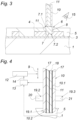
- Fig. 3 an electrical connection contact 6, via which the conductor track 4 can be electrically connected.
- the electrical connection contact 6 is formed by an electrically conductive contact element 7.
- contact element 7 projects through a recess 8 in the electrical insulation layer 5 to the electrical conductor track 4 and thus contacts the conductor track 4.
- the contact element 7 is electrically connected to the conductor track 4 at a first end 7.1, wherein the contact element 7 forms the electrical connection contact 6 at the other second end 7.2.
- the recess 8 is produced in a special way, namely, with the aid of a hollow needle 10 advanced in the direction 9 of the conductor track 4 - as shown in the Figures 1 and 2 can be seen according to a first embodiment.
- hollow needle 10 in the Figures 2 to 4 can also be one according to the Figures 5a, 5b hollow needle 110 shown may be used, which is generally mentioned.
- FIG. 1 the hollow needle 10 has penetrated into the coating 2 - after Fig. 2 this hollow needle 10 is shown already advanced to the conductor track 4.
- This insertion of the hollow needle 10 results in a particularly precisely running recess 8 in the coating 2 or in the electrical insulation layer 5.
- the hollow needle 10 When the hollow needle 10 is withdrawn from the recess 8, the hollow needle 10 introduces an electrically conductive viscous mass 11, namely a paste, into this recess 8, which creates the fixed contact element 7 in the recess 8, for example by hardening and/or drying, etc. of the mass 11.
- the withdrawn position of the hollow needle 10 comes into Fig. 3 to expression.
- the hollow needle 10 is comparatively easy to handle and the precisely extending recess 8 also allows a contact element 7 for an electrical connection contact 6 to be produced on the coated sheet 1 with precise positioning, the invention is distinguished from the prior art by its high reproducibility.
- the process of creating the recess 8 by the hollow needle 10 and introducing the conductive viscous mass 11 into this recess 8 when the hollow needle 10 is withdrawn can be carried out continuously, which speeds it up and also makes it more efficient.
- the penetration depth of the hollow needle 10 into the coating 2 is adjusted by a controller 12, which regulates/controls the feed rate 9 of the hollow needle 10.
- a measuring device 13 is assigned to the controller 12, which transmits to the controller 12 a measured variable 14 dependent on one of the dielectric constants between the hollow needle 10 and the sheet 1.
- This measurement which can be, for example, a capacitance measurement using the electrically conductive sheath 10.1 of the hollow needle 10 as a sensor 19.1, can be used to determine the distance of the hollow needle tip from the sheet 1 - whereby the feed rate of the hollow needle 10 in the direction of the sheet 1 can be limited or precisely adjusted.
- Inductive and/or eddy current sensors 19.2, 19.3 associated with the hollow needle 10 are also conceivable, as shown in Fig. 4 indicated can be recognized in order to be able to measure the distance reliably.
- the hollow needle points Fig. 4 a first electrical coil 20 as the second sensor 19.2, which first coil 20 is attached to the outside of the casing 10.1 of the hollow needle 10.
- first coil 20 is attached to the outside of the casing 10.1 of the hollow needle 10.
- eddy currents are induced in the conductor track and/or sheet.
- the electromagnetic shielding of the sheet 1 by the overlying conductor track 4 can be detected, and as a result, the distance between the hollow needle 10 and the conductor track 4 can be determined.
- the hollow needle 10 may have a second electrical coil 21 provided on the outside of the casing 10.1 as a third sensor 19.3.
- the first coil 20 serves to generate a magnetic field.
- a voltage is generated that is proportional to the magnetic field generated by the first coil.
- the magnetic flux generated by coil 20 is measured. Since the conductor track 4 embedded in the coating 2 causes a change in the magnetic flux, the hidden conductor track can be located based on the voltage at the second coil 21, and the distance between the hollow needle 10 and the conductor track 4 can also be calculated.
- the hollow needle 10 pierces the electrical insulation layer 5 to form the recess 8.
- the hollow needle 10 uses a machining process to form the recess 8.
- the hollow needle 10 can have at least one cutting edge (not shown in detail), for example from an indexable insert.
- the cutting edge (not shown in detail) can Fig. 4 or Fig. 5a on the casing 10.1 and/or on the head 10.2 of the hollow needle 10 in order to machine the electrical insulation layer 5.
- a secure electrical contact with low resistance is created by advancing the hollow needle 10 to the conductor side 4.1 of the electrical conductor track 4 facing the sheet 1.
- the viscous mass 11 is cured with a radiation source 15, namely a UV lamp, thereby creating a solid and thus dimensionally stable contact element 7.
- a radiation source namely a UV lamp
- a thermal heat source such as an IR lamp array
- the solidification (e.g., drying, curing, chemical crosslinking, etc.) of the viscous mass 11 can be performed during and/or after the introduction of the viscous mass 11 into the recess 8. It is also conceivable that the solidification of the viscous mass 11 takes place in a process step following the production of an electrical connection contact 6.
- the viscous mass 11 is pre-consolidated in the hollow needle 10, namely pre-hardened by cross-linking.
- the hollow needle has an electrically insulating coating 17 on the inside of the casing 10.1.
- An electrode 18, e.g., a Pt wire, is also provided centrally in the hollow needle 10. This electrode interacts with the electrically conductive casing 10.1 as a counter electrode to stimulate a chemical hardening reaction (e.g., polymerization) in the viscous mass 11 when electrical energy is applied between the two electrodes.
- a chemical hardening reaction e.g., polymerization
- the viscous mass 11 can be pre-dried and/or pre-cured in such a way that this mass 11 has a hardness that increases from the inside to the outside.
- a device 22 for the parallel production of several electrical connection contacts 6 is also provided in Fig. 1 can be seen as indicated.
- several hollow needles 10 are guided in parallel by the device 22, specifically with the same feed rate 9.
- the hollow needles 10 are positioned at a distance from one another on the sheet 1, for example, one after the other and next to one another, and can thus, for example, create the connecting contacts 6 of an electrical interface (not shown in detail). This can create an interface quickly in a simple and efficient manner.
- the hollow needle 110 has, according to a second embodiment, a closing nozzle 16 on the head 10.2.
- This closing nozzle 16 serves to open and close the opening 10.3 on the head 10.2 of the hollow needle 110.
- This is done with a tappet-shaped valve element 16.1 of the closing nozzle 16 allows which valve element 16.1 is arranged for linear movement in the hollow needle channel 10.4.
- the valve element 16.1 closes the opening 10.3 on the head 10.2.
- the valve element 16.1 is displaced back from the opening 10.3, thus allowing the flow of the electrically conductive, viscous mass 11.
- the hollow needle 110 thus always ensures a high-quality electrical connection contact 6, which particularly increases the stability of the process.
Landscapes
- Engineering & Computer Science (AREA)
- Microelectronics & Electronic Packaging (AREA)
- Manufacturing & Machinery (AREA)
- Measuring Leads Or Probes (AREA)
- Investigating Or Analyzing Materials By The Use Of Magnetic Means (AREA)
- Investigating Or Analyzing Materials By The Use Of Electric Means (AREA)
- Printing Elements For Providing Electric Connections Between Printed Circuits (AREA)
- Manufacturing Of Printed Wiring (AREA)
Description
- Die Erfindung betrifft eine Vorrichtung und ein Verfahren zur Herstellung eines elektrischen Anschlusskontakts an einem beschichteten Blech, dessen Beschichtung mindestens eine von einer elektrischen Isolationsschicht abgedeckte elektrische Leiterbahn aufweist, bei welchem Verfahren eine Ausnehmung durch die elektrische Isolationsschicht bis zumindest zur elektrischen Leiterbahn hin erzeugt wird und in diese Ausnehmung ein elektrisch leitendes Kontaktelement vorgesehen wird, das elektrisch an einem Ende an die Leiterbahn anschließt und am anderen Ende den elektrischen Anschlusskontakt ausbildet.
- Um eine Leiterbahn, die in einer Beschichtung auf einem Metallblech eingebettet ist, elektrisch anschließen zu können, ist es aus dem Stand der Technik bekannt (
EP1517597A2 ) einen Kontaktstift durch die elektrische Isolierung der Beschichtung hin bis zur elektrischen Leiterbahn zu stoßen. Dadurch schließt der Kontaktstift an einem Ende an die Leiterbahn elektrisch an, wobei sein anderes Ende einen elektrischen Anschlusskontakt ausbildet. Nachteilig kann sich solch ein Einstoßen eines Kontaktstifts als vergleichsweise schwer bzw. ungenau reproduzierbar erweisen - wobei zudem stoßbedingte Verformungen am Kontaktstift eine zielgerichtete Kontaktierung erschweren können. Verfahren des Stands der Technik sind daher vergleichsweise fehleranfällig. - Weiterer relevanter Stand der Technik ist in Dokument
US 5 844 753 A offenbart. - Eine Kanüle zum Ausbilden einer Durchkontaktierung oder Ausnehmung sowie zum Ausfüllen dieser mit Leitkleber ist aus der
DE10206440A1 bekannt. - Es ist daher Aufgabe der Erfindung, ein Verfahren zur Herstellung eines elektrischen Anschlusskontakts an einem beschichteten Blech der eingangs geschilderten Art zu vereinfachen bzw. zu verbessern - und damit die Reproduzierbarkeit des Verfahrens zu erhöhen.
- Die Erfindung löst die gestellte Aufgabe durch ein Verfahren nach Anspruch 1. Die Ausnehmung wird mit Hilfe einer in Richtung der Leiterbahn vorgeschobenen Hohlnadel ausgebildet, , die bei deren Zurückziehen aus der Ausnehmung eine elektrisch leitfähige, viskose Masse in diese Ausnehmung einbringt, um das Kontaktelement zu erzeugen.
- Wird die Ausnehmung mit Hilfe einer in Richtung der Leiterbahn vorgeschobenen Hohlnadel ausgebildet, kann unabhängig von der mechanischen Festigkeit eines Kontaktelements eine positionsgenaue und im Verlauf vergleichsweise exakte Ausnehmung in der Beschichtung geschaffen werden, welche die Beschichtung bis zur Leiterbahn hin öffnet. Unter anderem werden dadurch auch Kurzschlüsse, beispielsweise mit anderen Leiterbahnen, vermieden. Wird in solch einer Ausnehmung anschließend das Kontaktelement vorgesehen, indem die Hohlnadel beim Zurückziehen aus der Ausnehmung in die Ausnehmung eine elektrisch leitfähige, viskose Masse einbringt, um das Kontaktelement zu erzeugen, kann die exakte Ausnehmung zur genauen Formgebung des Kontaktelements genützt werden - und damit auch eine in ihren elektrischen Eigenschaften gleiche elektrische Verbindung zwischen dem äußeren Anschlusskontakt und der elektrischen Leiterbahn reproduzierbar zur Verfügung gestellt werden. Zudem ist dieses Vorschieben bzw. Zurückziehen einer Hohlnadel vergleichsweise einfach handhabbar, was die Reproduzierbarkeit des Verfahrens weiter erhöhen kann.
- Die Reproduzierbarkeit des Verfahrens kann weiter erhöht werden, wenn als viskose Masse eine Paste oder eine Tinte eingebracht wird.
- Im Allgemeinen wird erwähnt, dass als elektrisch leitfähige Paste/Tinte zur Ausbildung des Kontaktelements ein elektrisch leitfähiges Polymer, beispielsweise Polyanilin, Polypyrrol oder Polythiophen, verwendet werden kann. Solch eine Paste/Tinte kann stattdessen auch eine metallische Basis, wie beispielsweise Silber, Kupfer oder Gold, eine organische Basis, wie beispielsweise PEDOT ((Poly- 3,4-ethylendioxythiophene) oder eine Graphen-Basis aufweisen. Ebenso ist hierfür Carbon oder Graphit denkbar. Tinten/Pasten mit metallischer Basis können sich durch eine besonders günstige Leitfähigkeit auszeichnen, wohingegen Tinten und/oder Pasten mit organischer Basis zumeist eine erhöhte Korrosionsbeständigkeit bieten können. Eine Paste weist im Allgemeinen eine höhere Viskosität auf, beispielsweise > 50 mPa·s, bevorzugt > 1 Pa·s, als eine Tinte. Beispielsweise kann PEDOT:PSS als Tinte als auch als Paste hergestellt werden. Dies ist beispielsweise über die Menge an Lösungsmittel, wie beispielsweise Wasser oder Isopropanol, einstellbar.
- Die Kontaktierung der Leiterbahn kann weiter verbessert werden, wenn beim Vorschieben der Hohlnadel zumindest eine Messgröße, welche vom Abstand zwischen Hohlnadel und Leiterbahn abhängt, gemessen wird, um die Vorschubtiefe der Hohlnadel in Richtung des Blechs zu begrenzen. Damit kann die Tiefe der Ausnehmung selbst bei variierenden Beschichtungsdicken besonders exakt bestimmt und eingestellt werden - was wiederum die Reproduzierbarkeit des Verfahrens erhöhen kann.
- Die Vorschubtiefe kann beispielsweise reproduzierbar eingestellt werden, wenn diese Messgröße, welche von einer der Dielektrizitätskonstanten zwischen Hohlnadel und Leiterbahn abhängt, gemessen wird.
- Alternativ ist vorstellbar, dass die Vorschubtiefe dadurch eingestellt wird, in dem eine vom Wirbelstromprinzip abhängige Messgröße gemessen wird.
- Auch kann die Vorschubtiefe dadurch exakt eingestellt werden, in dem eine vom induktiven Messprinzip abhängige Messgröße gemessen wird.
- Durchstößt die Hohlnadel die elektrische Isolationsschicht, kann durch Verdrängung der Beschichtung - selbst bei einem eventuellen Schwinden des Kontaktelements durch Härten bzw. Trocknen der viskosen Masse eine exakte Lagefixierung des Kontaktelements sichergestellt bleiben.
- Eine widerstandsarme Kontaktierung der Leiterbahn kann erreicht werden, wenn die Hohlnadel bis auf die dem Blech zugewandte Leiterseite der elektrischen Leiterbahn vorgeschoben wird. Dies kann die Reproduzierbarkeit des Verfahrens weiter erhöhen.
- Ein standfester elektrischer Anschlusskontakt kann erzeugt werden, wenn die viskose Masse getrocknet und/oder gehärtet wird, um ein festes Kontaktelement zu erzeugen.
- Das Härten und/oder Trocknen der Masse kann hierbei direkt nach der Einbringung aktiv oder passiv erfolgen. Bei einer passiven Aushärtung, wie beispielsweise bei einer Silberpaste, wird diese an Luft gehärtet und/oder getrocknet, ohne dies aktiv zu beschleunigen. Ein derartiger Verfahrensschritt ist vergleichsweise einfach zu handhaben, was die Reproduzierbarkeit des Verfahrens erhöhen kann. Vorzugsweise wird ein passives Härten und/oder Trocknen bei pastösen viskosen Massen, nämlich Pasten, durchgeführt, da diese resistenter gegenüber unerwünschten Formänderung an der Ausnehmung, beispielsweise durch ein Rückspringen und/oder Zurückfließen der elektrischen Isolationsschicht, sind.
- Eine aktive Härtung und/oder Trocknung kann durch eine UV-Bestrahlung oder Beheizung der eingebrachten leitfähigen Paste erfolgen. Vor allem bei niedrigviskosen Tinten ist eine aktive Härtung von Vorteil. Dabei kann beispielsweise direkt nach der Einbringung und/oder während des Zurückziehens der Hohlnadel die viskose Masse mit UV-Strahlen beaufschlagt. Solch eine aktive Härtung und/oder Trocknung bietet sich besonders bei niedrigviskosen Massen an, wie beispielsweise bei Tinten, da diese besonders anfällig gegenüber einer unerwünschten Formänderung an der Ausnehmung sind.
- Alternativ kann eine thermische Behandlung mit beispielsweise einem Infrarot-Lampenfeld bei 40°C bis 150°C bevorzugt 60°C bis 100°C für insbesondere 0,5 bis 100 Sekunden bevorzugt 5 bis 60 Sekunden vorgesehen sein, um damit die Aushärtung beschleunigen zu können.
- Wird vor dem Einbringen der viskosen Masse diese in der Hohlnadel vorgetrocknet und/oder vorgehärtet, kann dies der Formgenauigkeit des Kontaktelements dienlich sein. Solch eine "in-situ" Härtung kann beispielsweise elektrochemisch erfolgen. Vorstellbar ist hierbei über eine Kontaktstelle an der Leiterbahn zur Hohlnadel hin elektrische Energie zu übertragen, wodurch die viskose Masse beispielsweise in der chemischen Reaktion zur Aushärtung angeregt werden kann. Vorstellbar ist zudem, dass diese elektrische Anregung in der Hohlnadel selbst erfolgt. Vorteilhafterweise kann hiermit die Geschwindigkeit der Aushärtereaktion über die Regelung des Stroms direkt und verhältnismäßig einfach gesteuert werden.
- Die Formgenauigkeit des Kontaktelements kann weiter verbessert werden, wenn die viskose Masse derart vorgetrocknet und/oder vorgehärtet wird, dass diese viskose Masse von innen nach außen eine zunehmende Härte aufweist. Des Weiteren kann diese Aushärtung vermehrt an der Grenzfläche das Verfahren effizient und reproduzierbar machen und auch die Formstabilität der eingebrachten Paste weiter erhöhen. Hinzu kommt, dass eine derartige Vortrocknung und/oder Vorhärtung ein Spiel zwischen der Ausnehmung und dem Kontaktelement schaffen kann, in welche Kavität gegebenenfalls elektronische/elektrische Bauelemente/teile oder andere Materialien vorsehbar sind.
- Ist beim Ausbilden der Ausnehmung mit Hilfe der in Richtung der Leiterbahn vorgeschobenen Hohlnadel deren Öffnung am Kopf verschlossen, kann verhindert werden, dass in den Hohlkanal Verneigungen eindringen. Damit kann reproduzierbar ein hochwertiges Kontaktelement erzeugt werden, in dem beim Zurückziehen der Hohlnadel aus der Ausnehmung deren Öffnung am Kopf offen ist, über diese Öffnung die elektrisch leitfähige, viskose Masse in diese Ausnehmung einzubringen.
- Die Erfindung hat sich außerdem die Aufgabe gestellt, eine Vorrichtung zu schaffen, mit der ein elektrischer Anschlusskontakt an einem beschichteten Blech standfest hergestellt werden kann.
- Die Erfindung löst die gestellte Aufgabe durch eine Vorrichtung nach Anspruch 12 mit mindestens einer Hohlnadel, die eine viskose Masse aufnimmt und wenigstens einen Sensor zur Erfassung von mindesten einer zur Hohlnadel abstandsabhängige Messgröße aufweist.
- Nimmt die Hohlnadel eine viskose Masse auf und weist die Hohlnadel wenigstens einen Sensor zur Erfassung von mindestens einer zur Hohlnadel abstandsabhängigen Messgröße auf, kann ein vergleichsweise einfach konstruiertes Mittel zur Verfügung stehen, mit dem zuverlässig ein elektrischer Anschlusskontakt erstellt werden kann. Diese zur Hohlnadel abstandsabhängige Messgröße kann beispielsweise vom Abstand zwischen Hohlnadel und Leiterbahn, vom Abstand zwischen Hohlnadel und Blech, etc. abhängen.
- Ein in der Herstellung eines elektrischen Anschlusskontakts an einem beschichteten Blech verfahrensschnelle Vorrichtung kann geschaffen werden, wenn die Vorrichtung mehrere parallel geführte Hohlnadeln zur gemeinsamen Erzeugung von mehrere elektrische Anschlusskontakten aufweist.
- Weist die Hohlnadel an der Öffnung deren Kopfs eine Verschlussdüse auf, kann beim Vorschieben der Hohlnadel zur Ausbildung der Ausnehmung eine vollständige Verdrängung des Materials, beispielsweise von der Isolationsschicht, vor der Hohlnadel sichergestellt werden. Beispielsweise kann damit auch ein Eindringen von Material in den Hohlnadelkanal der Hohlnadel verhindert und eine Beeinträchtigung der elektrisch leitfähigen, viskosen Masse vermieden werden. Dies kann eine standfestere Herstellung eines elektrischen Anschlusskontakts ermöglichen. Ist zudem ein Ventilelement der Verschlussdüse im Hohlnadelkanal zum Öffnen oder Verschließen der Öffnung am Kopf beweglich angeordnet, kann trotz einer Verschlussdüse am Kopf die Hohlnadel schlanken Abmessungen genügen und damit das Vorschieben der Hohlnadel erleichtern.
- In den Figuren sind beispielsweise Verfahrensschritte des erfindungsgemäßen Verfahrens dargestellt. Es zeigen
- Fig. 1
- eine Schnittansicht auf ein beschichtetes Blech mit in dessen Beschichtung eingedrungenen Hohlnadel nach einem ersten Ausführungsbeispiel,
- Fig. 2
- eine Schnittansicht auf das nach
Fig. 1 dargestellte Blech mit zurückgezogener Hohlnadel, - Fig. 3
- eine Schnittansicht auf das nach
Fig. 1 dargestellte Blech mit einem Anschlusskontakt, - Fig. 4
- eine abgerissene und vergrößerte Schnittansicht auf die Hohlnadel nach
Fig. 1 und - Fig. 5a, 5b
- eine Hohlnadel nach einem zweiten Ausführungsbeispiel.
- Nach den
Figuren 1, 2 und3 wird ein Blech 1, vorzugsweise Feinblech, insbesondere aus einem Stahlwerkstoff, gezeigt, welches Blech 1 mit einer Beschichtung 2 versehen ist. Diese Beschichtung 2 besteht aus einer auf das Blech 1 aufgebrachten Grundierung 3, beispielsweise Primer, einer an der Grundierung vorgesehenen elektrische Leiterbahn 4 und einer elektrischen Isolationsschicht 5, beispielsweise ein Decklack, der die Leiterbahn 4 nach außen abdeckt. - Zudem ist in
Fig. 3 ein elektrischer Anschlusskontakt 6 zuerkennen, über welchen die Leiterbahn 4 elektrisch angeschlossen werden kann. Der elektrische Anschlusskontakt 6 wird von einem elektrisch leitenden Kontaktelement 7 ausgebildet. Das Kontaktelement 7 ragt hierzu durch eine Ausnehmung 8 in der elektrischen Isolationsschicht 5 bis zur elektrischen Leiterbahn 4 und kontaktiert somit die Leiterbahn 4. Dadurch ist das Kontaktelement 7 an einem ersten Ende 7.1 mit der Leiterbahn 4 elektrisch verbunden, wobei das Kontaktelement 7 am anderen zweiten Ende 7.2 den elektrischen Anschlusskontakt 6 ausbildet. - Erfindungsgemäß wird die Ausnehmung 8 in besonderer Weise erzeugt, nämlich, mit Hilfe einer in Richtung 9 der Leiterbahn 4 vorgeschobenen Hohlnadel 10 - wie dies in den
Figuren 1 und 2 nach einem ersten Ausführungsbeispiel zu erkennen ist. - Anstatt der Hohlnadel 10 in den
Figuren 2 bis 4 kann auch eine nach denFiguren 5a, 5b dargestellte Hohlnadel 110 verwendet werden, was im Allgemeinen erwähnt wird. - Entsprechend
Fig. 1 ist die Hohlnadel 10 in die Beschichtung 2 eingedrungen - nachFig. 2 ist diese Hohlnadel 10 bereits bis zur Leiterbahn 4 vorgeschoben dargestellt. - Durch diese Einbringung der Hohlnadel 10 ergibt sich eine besonders exakt verlaufende Ausnehmung 8 in der Beschichtung 2 bzw. in der elektrischen Isolationsschicht 5.
- Beim Zurückziehen der Hohlnadel 10 aus der Ausnehmung 8 heraus, bringt die Hohlnadel 10 in diese Ausnehmung 8 eine elektrisch leitfähige viskose Masse 11, nämlich eine Paste, ein, welche das feste Kontaktelement 7 in der Ausnehmung 8 erzeugt, beispielsweise durch Aushärten und/oder Trocknen, etc. der Masse 11. Die zurückgezogene Position der Hohlnadel 10 kommt in
Fig. 3 zum Ausdruck. - Da die Hohlnadel 10 vergleichsweise einfach handhabbar ist und durch die exakt verlaufende Ausnehmung 8 auch ein positionsgenaues Kontaktelement 7 für einen elektrischen Anschlusskontakt 6 am beschichteten Blech 1 erzeugt werden kann, zeichnet sich die Erfindung gegenüber dem Stand der Technik durch hohe Reproduzierbarkeit aus.
- Zudem kann in der Schaffung der Ausnehmung 8 durch die Hohlnadel 10 und der Einbringung der leitfähigen viskosen Masse 11 in diese Ausnehmung 8 beim Zurückziehen der Hohlnadel 10 das Verfahren kontinuierlich ablaufen, was es beschleunigt und auch effizienter gestaltet.
- Die Eindringtiefe der Hohlnadel 10 in die Beschichtung 2 wird von einer Steuerung 12 eingestellt, welche den Vorschub 9 der Hohlnadel 10 regelt/steuert. Hierzu ist der Steuerung 12 eine Messeinrichtung 13 zugeordnet, die der Steuerung 12 eine von einer der Dielektrizitätskonstanten zwischen Hohlnadel 10 und Blech 1 abhängende Messgröße 14 übermittelt. Über diese Messung, welche beispielsweise eine Kapazitätsmessung unter Verwendung des elektrisch leitfähigen Mantels 10.1 der Hohlnadel 10 als Sensor 19.1, sein kann, ist der Abstand der Hohlnadelspitze vom Blech 1 ermittelbar - womit die Vorschubtiefe der Hohlnadel 10 in Richtung des Blechs 1 begrenzt bzw. exakt eingestellt werden kann.
- Alternativ oder zusätzlich zu diesem kapazitiv wirkenden, ersten Sensor 19.1 der Hohlnadel 10 nach
Fig. 4 sind auch der Hohlnadel 10 zugehörige induktive und/oder nach dem Wirbelstromprinzip wirkende Sensoren 19.2, 19.3 denkbar, wie diese inFig. 4 angedeutete zu erkennen sind, um damit die Abstandsmessung zuverlässig vornehmen zu können. - Hierzu weist die Hohlnadel nach
Fig. 4 eine erste elektrische Spule 20 als zweiten Sensor 19.2 auf, welche erste Spule 20 außen am Mantel 10.1 der Hohlnadel 10 angebracht ist. Mit Hilfe dieser ersten Spule 20 werden Wirbelströme in der Leiterbahn und/oder Blech induziert. Auf Basis der Änderung der Impedanz der ersten Spule 20 kann die elektromagnetische Abschirmung des Blechs 1 durch die darüberlegende Leiterbahn 4 detektiert und in Folge dessen auf den Abstand der Hohlnadel 10 zur Leiterbahn 4 geschlossen werden. - Alternativ oder zusätzlich kann die Hohlnadel 10 einen am Mantel 10.1 außen vorgesehene, zweite elektrische Spule 21 als dritter Sensor 19.3 aufweisen. Die erste Spule 20 dient bei dieser Messmethode zur Erzeugung eines Magnetfeldes. Mit Hilfe der zweiten Spule 21 wird eine Spannung, die proportional zum von der ersten Spule 20 erzeugten magnetischen Fluss ist, gemessen. Da es durch die in der Beschichtung 2 eingebettete Leiterbahn 4 zu einer Veränderung des magnetischen Flusses kommt, kann anhand der Spannung an der zweiten Spule 21 die verdeckte Leiterbahn aufgefunden und auch der Abstand der Hohlnadel 10 zur Leiterbahn 4 berechnet werden.
- Wie in den
Figuren 1 und 2 zu erkennen, durchstößt die Hohlnadel 10 die elektrische Isolationsschicht 5, um die Ausnehmung 8 zu bilden. Es ist aber auch vorstellbar, dass die Hohlnadel 10 ein spanendes Verfahren zur Ausbildung der Ausnehmung 8 verwendet. Hierzu kann die Hohlnadel 10 mindestens eine nicht näher dargestellte Schneide aufweisen, beispielsweise von einer Wendeschneidplatte. Die nicht näher dargestellte Schneide kann nachFig. 4 oderFig. 5a am Mantel 10.1 und/oder am Kopf 10.2 der Hohlnadel 10 vorgesehenen sein, um die elektrische Isolationsschicht 5 zu zerspanen. - Ein sicherer elektrischer Kontakt mit geringem Widerstand wird geschaffen, indem die Hohlnadel 10 bis zur dem Blech 1 zugewandte Leiterseite 4.1 der elektrischen Leiterbahn 4 vorgeschoben wird.
- Die viskose Masse 11 wird mit einer Strahlungsquelle 15, nämlich einer UV-Lampe, gehärtet, wodurch ein festes und damit formstabiles Kontaktelement 7 erzeugt wird. Alternativ oder zusätzlich kann zur UV-Lampe eine thermische Wärmequelle wie beispielsweise ein IR-Lampenfeld vorgesehen sein. Die Verfestigung (z. B.: Trocknung, Härtung, chemische Vernetzung, etc.) der viskose Masse 11 kann während und/oder nach der Einbringung der viskosen Masse 11 in die Ausnehmung 8 vorgenommen werden. Auch ist vorstellbar, dass die Verfestigung der viskosen Masse 11 in einem, der Herstellung eines elektrischen Anschlusskontakts 6 nachfolgenden Verfahrensschritt erfolgt.
- Zudem wird -wie in
Fig. 4 im Detail zu erkennen- vor dem Einbringen der viskosen Masse 11 diese in der Hohlnadel 10 vorverfestigt, nämlich durch Vernetzen vorgehärtet. Hierzu weist die Hohlnadel am Mantel 10.1 innenliegend eine elektrisch isolierende Beschichtung 17 auf. In der Hohlnadel 10 ist zudem zentrisch eine Elektrode 18, z. B. ein Pt-Draht, vorgesehen, die mit dem elektrisch leitenden Mantel 10.1 als Gegenelektrode zusammenwirkt, beim Anlegen von elektrischer Energie zwischen den beiden Elektroden eine chemische Härtungsreaktion (z. B.: Polymerisation) an der viskosen Masse 11 anzuregen. Damit kann eine in-situ Aushärtung der viskosen Masse 11 vor einem Einbringen in die Ausnehmung 8 bereits vorgenommen werden. Insbesondere kann dadurch die viskose Masse 11 derart vorgetrocknet und/oder vorgehärtet werden, dass diese Masse 11 eine von innen nach außen zunehmende Härte aufweist. - Eine Vorrichtung 22 zur parallelen Herstellung von mehreren elektrischen Anschlusskontakten 6 ist zudem in
Fig. 1 angedeutet zu erkennen. Hier werden mehrere Hohlnadeln 10 von der Vorrichtung 22 parallel geführt, und zwar mit gleichem Vorschub 9. Die Hohlnadeln 10 sind voneinander beabstandet am Blech 1 positioniert, beispielsweise nach- und nebeneinander und können damit beispielsweise die Anschlusskontakte 6 einer nicht näher dargestellten elektrischen Schnittstelle schaffen. Dies kann in einer einfach handhabbaren und effizienten Art und Weise verfahrensschnell eine Schnittstelle schaffen. - Im Allgemeinen wird weiter erwähnt, dass die Form der Hohlnadel stumpf oder spitz zulaufend sein kann. Bei einem stumpfen Eindringen wird die elektrische Isolationsschicht einer möglichst geringen Belastung ausgesetzt, wohingegen bei einer spitz zulaufenden Form die Eindringkraft reduziert werden kann. Des Weiteren kann bei einer stumpfen Form die Erfassung von Messdaten erleichtern und damit das Verfahren präziser gestalten.
- Wie in den
Figuren 5a und 5b zu erkennen, weist die Hohlnadel 110 nach einer zweiten Ausführungsform am Kopf 10.2 eine Verschlussdüse 16 auf. Diese Verschlussdüse 16 dient zum Öffnen und Verschließen der Öffnung 10.3 am Kopf 10.2 der Hohlnadel 110. Dies wird mit einem stößelförmigen Ventilelement 16.1 der Verschlussdüse 16 ermöglicht, welches Ventilelement 16.1 im Hohlnadelkanal 10.4 linear beweglich angeordnet ist. Bei geschlossener Verschlussdüse 16 verschließt das Ventilelement 16.1 die Öffnung 10.3 am Kopf 10.2 passend und bei geöffneter Verschlussdüse 16 ist das Ventilelement 16.1 gegenüber der Öffnung 10.3 zurückverlagert und gibt damit den Durchfluss für die elektrisch leitfähige, viskose Masse 11 frei. Dies verhindert eine innere Kontamination der Hohlnadel 110 bzw. deren elektrisch leitfähigen, viskosen Masse 11. Dies beispielsweise, wenn die Hohlnadel 110 zur Ausbildung der Ausnehmung 8 durch ein Material vorgeschoben wird. Die erfindungsgemäße Hohlnadel 110 sorgt sohin stets für einen hochwertigen elektrischen Anschlusskontakt 6, was die Standfestigkeit des Verfahrens besonders erhöht.
Claims (14)
- Verfahren zur Herstellung eines elektrischen Anschlusskontakts (6) an einem beschichteten Blech (1), dessen Beschichtung (2) mindestens eine von einer elektrischen Isolationsschicht (5) abgedeckte elektrische Leiterbahn (4) aufweist, bei welchem Verfahren eine Ausnehmung (8) durch die elektrische Isolationsschicht (5) bis zumindest zur elektrischen Leiterbahn (4) hin erzeugt wird und in diese Ausnehmung (8) ein elektrisch leitendes Kontaktelement (7) vorgesehen wird, das elektrisch an einem Ende (7.2) an die Leiterbahn (4) anschließt und am anderen Ende (7.1) den elektrischen Anschlusskontakt (6) ausbildet, dadurch gekennzeichnet, dass die Ausnehmung (8) mit Hilfe einer in Richtung der Leiterbahn (4) vorgeschobenen Hohlnadel (10) ausgebildet wird, die bei deren Zurückziehen aus der Ausnehmung (8) eine elektrisch leitfähige, viskose Masse (11) in diese Ausnehmung (8) einbringt, um das Kontaktelement (7) zu erzeugen, wobei beim Vorschieben der Hohlnadel (10) zumindest eine Messgröße (14), welche vom Abstand zwischen Hohlnadel (10) und Leiterbahn (4) abhängt, gemessen wird, um die Vorschubtiefe der Hohlnadel (10) in Richtung des Blechs (1) zu begrenzen.
- Verfahren nach Anspruch 1, dadurch gekennzeichnet, dass als viskose Masse (11) eine Paste oder eine Tinte eingebracht wird.
- Verfahren nach Anspruch 1, dadurch gekennzeichnet, dass eine Messgröße (14), welche von einer der Dielektrizitätskonstanten zwischen Hohlnadel (10) und Leiterbahn (4) abhängt, gemessen wird.
- Verfahren nach Anspruch 1, dadurch gekennzeichnet, dass eine vom Wirbelstromprinzip abhängige Messgröße (14) gemessen wird.
- Verfahren nach Anspruch 1, dadurch gekennzeichnet, dass eine vom induktiven Messprinzip abhängige Messgröße (14) gemessen wird.
- Verfahren nach einem der Ansprüche 1 bis 5, dadurch gekennzeichnet, dass die Hohlnadel (10) die elektrische Isolationsschicht (5) durchstößt.
- Verfahren nach einem der Ansprüche 1 bis 6, dadurch gekennzeichnet, dass die Hohlnadel (10) bis auf die dem Blech (1) zugewandte Leiterseite (4.1) der elektrischen Leiterbahn (4) vorgeschoben wird.
- Verfahren nach einem der Ansprüche 1 bis 7, dadurch gekennzeichnet, dass die viskose Masse (11) getrocknet und/oder gehärtet wird, um ein festes Kontaktelement (7) zu erzeugen.
- Verfahren nach Anspruch 8, dadurch gekennzeichnet, dass vor dem Einbringen der viskosen Masse (11) diese in der Hohlnadel (10) vorgetrocknet und/oder vorgehärtet wird.
- Verfahren nach Anspruch 9, dadurch gekennzeichnet, dass viskose Masse (11) derart vorgetrocknet und/oder vorgehärtet wird, dass diese viskose Masse (11) von Innen nach Außen eine zunehmende Härte aufweist.
- Verfahren nach einem der Ansprüche 1 bis 10, dadurch gekennzeichnet, dass beim Ausbilden der Ausnehmung (8) mit Hilfe der in Richtung der Leiterbahn (4) vorgeschobenen Hohlnadel (10) deren Öffnung (10.3) am Kopf (10.2) verschlossen ist, und dass beim Zurückziehen der Hohlnadel (10) aus der Ausnehmung (8) deren Öffnung (10.3) am Kopf (10.2) offen ist, über diese Öffnung (10.3) die elektrisch leitfähige, viskose Masse (11) in diese Ausnehmung (8) einzubringen, das Kontaktelement (7) zu erzeugen.
- Vorrichtung eingerichtet zur Durchführung des Verfahrens nach einem der Ansprüche 1 bis 11 mit mindestens einer Hohlnadel (10), die eine viskose Masse (11) aufnimmt und wenigstens einen Sensor (19.1, 19.2, 19.3) zur Erfassung von mindestens einer Messgröße (14) aufweist, welche Messgröße (14) vom Abstand zwischen Hohlnadel (10) und Leiterbahn (4) des Blechs (1) abhängt.
- Vorrichtung nach Anspruch 12, dadurch gekennzeichnet, dass die Vorrichtung (22) mehrere parallel geführte Hohlnadeln (10) zur gemeinsamen Erzeugung von mehrere elektrische Anschlusskontakten (6) aufweist.
- Vorrichtung nach Anspruch 12 oder 13, dadurch gekennzeichnet, dass die Hohlnadel (10) an der Öffnung (10.3) deren Kopfs (10.2) eine Verschlussdüse (16) aufweist, wobei ein Ventilelement (16.1) der Verschlussdüse (16) im Hohlnadelkanal (10.4) zum Öffnen oder Verschließen der Öffnung (10.3) am Kopf (10.2) beweglich angeordnet ist.
Applications Claiming Priority (2)
| Application Number | Priority Date | Filing Date | Title |
|---|---|---|---|
| EP17178878.9A EP3422828A1 (de) | 2017-06-29 | 2017-06-29 | Verfahren und vorrichtung zur herstellung eines elektrischen anschlusskontakts - kontaktinator |
| PCT/EP2018/067620 WO2019002567A1 (de) | 2017-06-29 | 2018-06-29 | Vorrichtung und verfahren zur herstellung eines elektrischen anschlusskontakts an einem beschichteten blech |
Publications (2)
| Publication Number | Publication Date |
|---|---|
| EP3646677A1 EP3646677A1 (de) | 2020-05-06 |
| EP3646677B1 true EP3646677B1 (de) | 2025-04-09 |
Family
ID=59258138
Family Applications (2)
| Application Number | Title | Priority Date | Filing Date |
|---|---|---|---|
| EP17178878.9A Withdrawn EP3422828A1 (de) | 2017-06-29 | 2017-06-29 | Verfahren und vorrichtung zur herstellung eines elektrischen anschlusskontakts - kontaktinator |
| EP18743405.5A Active EP3646677B1 (de) | 2017-06-29 | 2018-06-29 | Verfahren und vorrichtung zur herstellung eines elektrischen anschlusskontakts an einem beschichteten blech |
Family Applications Before (1)
| Application Number | Title | Priority Date | Filing Date |
|---|---|---|---|
| EP17178878.9A Withdrawn EP3422828A1 (de) | 2017-06-29 | 2017-06-29 | Verfahren und vorrichtung zur herstellung eines elektrischen anschlusskontakts - kontaktinator |
Country Status (6)
| Country | Link |
|---|---|
| US (1) | US11558965B2 (de) |
| EP (2) | EP3422828A1 (de) |
| JP (1) | JP2020526038A (de) |
| KR (1) | KR102572157B1 (de) |
| CN (1) | CN110959313A (de) |
| WO (1) | WO2019002567A1 (de) |
Family Cites Families (21)
| Publication number | Priority date | Publication date | Assignee | Title |
|---|---|---|---|---|
| DE2740429C2 (de) * | 1977-09-08 | 1983-01-27 | Ludwig Scheid GmbH Spezialpräparate und Gewürze zur Fleischverarbeitung, 6621 Überherrn | Verfahren und Vorrichtung zum Trockenpökeln von Fleisch oder Fisch |
| JP2506491B2 (ja) * | 1990-08-24 | 1996-06-12 | 富士通株式会社 | 粘液体の塗布方法とその装置 |
| JP2855414B2 (ja) * | 1995-04-13 | 1999-02-10 | 日本メクトロン株式会社 | 磁気ヘッド用中継基板及びその製造法 |
| FR2738077B1 (fr) * | 1995-08-23 | 1997-09-19 | Schlumberger Ind Sa | Micro-boitier electronique pour carte a memoire electronique et procede de realisation |
| FR2779851B1 (fr) * | 1998-06-12 | 2002-11-29 | Gemplus Card Int | Procede de fabrication d'une carte a circuit integre et carte obtenue |
| JP2000317352A (ja) * | 1999-05-07 | 2000-11-21 | Musashi Eng Co Ltd | 液体定量装置用のノズル |
| US6715506B1 (en) * | 1998-12-28 | 2004-04-06 | Musashi Engineering, Inc. | Method and device for injecting a fixed quantity of liquid |
| FR2816107B1 (fr) * | 2000-10-30 | 2003-11-28 | Gemplus Card Int | Module de circuit integre sur film et son procede de fabrication |
| DE10109087A1 (de) | 2001-02-24 | 2002-10-24 | Leoni Bordnetz Sys Gmbh & Co | Verfahren zum Herstellen eines Formbauteils mit einer integrierten Leiterbahn |
| DE10206440A1 (de) * | 2001-04-30 | 2002-11-14 | Isa Conductive Microsystems Gm | Verfahren und Vorrichtung zum Herstellen elektrisch leitender Verbindungen |
| JP2004111074A (ja) * | 2002-09-13 | 2004-04-08 | Toshiba Corp | 有機el表示装置の製造装置と、その製造方法 |
| JP3879751B2 (ja) * | 2004-07-27 | 2007-02-14 | セイコーエプソン株式会社 | コンタクトホールの形成方法、回路基板の製造方法、及び、電気光学装置の製造方法 |
| US7589018B2 (en) * | 2006-11-09 | 2009-09-15 | Seiko Epson Corporation | Method of forming contact hole, method of manufacturing wiring board, method of manufacturing semiconductor device, and method of manufacturing electro-optical device |
| JP2008177499A (ja) * | 2007-01-22 | 2008-07-31 | Seiko Epson Corp | コンタクトホールの形成方法、配線基板の製造方法、半導体装置の製造方法および電気光学装置の製造方法 |
| JP4300587B2 (ja) * | 2006-11-09 | 2009-07-22 | セイコーエプソン株式会社 | コンタクトホールの形成方法、これを用いた回路基板及び半導体装置の製造方法 |
| JP2008293821A (ja) * | 2007-05-25 | 2008-12-04 | Panasonic Corp | 導電性ペースト、それを用いた回路基板および電子電気機器 |
| US8765212B2 (en) * | 2007-09-21 | 2014-07-01 | Nordson Corporation | Methods for continuously moving a fluid dispenser while dispensing amounts of a fluid material |
| JP5262616B2 (ja) * | 2007-12-14 | 2013-08-14 | セイコーエプソン株式会社 | 液体噴射装置、液体貯留部材、及び、液体噴射装置の制御方法 |
| JP4986901B2 (ja) * | 2008-03-18 | 2012-07-25 | トッパン・フォームズ株式会社 | スルーホール形成方法及びスルーホール形成機構 |
| CN102883522B (zh) * | 2012-09-28 | 2015-08-26 | 华为技术有限公司 | 印刷电路板、印刷电路板的钻孔方法和装置 |
| JP2015090838A (ja) * | 2013-11-07 | 2015-05-11 | 株式会社日本マイクロニクス | 配線形成装置及び配線形成方法 |
-
2017
- 2017-06-29 EP EP17178878.9A patent/EP3422828A1/de not_active Withdrawn
-
2018
- 2018-06-29 KR KR1020207000787A patent/KR102572157B1/ko active Active
- 2018-06-29 EP EP18743405.5A patent/EP3646677B1/de active Active
- 2018-06-29 WO PCT/EP2018/067620 patent/WO2019002567A1/de not_active Ceased
- 2018-06-29 CN CN201880044061.4A patent/CN110959313A/zh active Pending
- 2018-06-29 US US16/627,680 patent/US11558965B2/en active Active
- 2018-06-29 JP JP2019572615A patent/JP2020526038A/ja active Pending
Also Published As
| Publication number | Publication date |
|---|---|
| EP3422828A1 (de) | 2019-01-02 |
| CN110959313A (zh) | 2020-04-03 |
| JP2020526038A (ja) | 2020-08-27 |
| US11558965B2 (en) | 2023-01-17 |
| KR102572157B1 (ko) | 2023-08-28 |
| US20200229310A1 (en) | 2020-07-16 |
| EP3646677A1 (de) | 2020-05-06 |
| KR20200032686A (ko) | 2020-03-26 |
| WO2019002567A1 (de) | 2019-01-03 |
Similar Documents
| Publication | Publication Date | Title |
|---|---|---|
| EP2490813B1 (de) | Elektrisch leitfähige pipettenspitze | |
| DE102013209407A1 (de) | Verfahren zur lötfreien elektrischen Einpresskontaktierung von elektrisch leitfähigen Einpress-Stiften in Leiterplatten | |
| DE19640670B4 (de) | Bipolare Elektrode | |
| EP3646677A1 (de) | Vorrichtung und verfahren zur herstellung eines elektrischen anschlusskontakts an einem beschichteten blech | |
| WO1997015347A1 (de) | Stimulationseinrichtung | |
| DE102016101619A1 (de) | Verfahren zur Herstellung einer Elektrodenleitung oder eines Katheters und dazugehöriges Halbzeug | |
| DE102018130719B3 (de) | Verfahren zur Gütebestimmung einer Sinterpastenschicht oder einer Sintermetallschicht und Vorrichtung hierzu | |
| EP3454631B1 (de) | Verfahren zur herstellung eines elektrischen anschlusskontakts an einem beschichteten blech | |
| EP2649870A2 (de) | Elektrische schaltungsanordnung sowie verfahren zur herstellung einer elektrischen schaltungsanordnung | |
| EP1057202A1 (de) | Verfahren und anordnung zur belichtung eines substrates | |
| EP3492795B1 (de) | Schlauch mit gedruckter elektronik | |
| EP1354610A1 (de) | Elektrodenleitung aus einem intrinsisch leitfähigen Polymer | |
| WO2015018829A1 (de) | Elektromechanisches anzündhütchen | |
| WO2015082179A1 (de) | Verfahren zum ausbilden einer elektrisch leitfähigen struktur auf einem kunststoffsubstrat | |
| EP3643149A1 (de) | Durchkontaktierung in einer beidseitig bedruckten trägerfolie | |
| EP1525900A1 (de) | Verfahren zur Herstellung eines elektrisch kontaktierbaren Bereichs auf einem dotierten Polymer Elektrode und nach dem Verfahren herstellbarer Formkörper | |
| DE102022206645B4 (de) | Transfermoldverfahren zum Umspritzen eines elektronischen Bauteils, Moldeinrichtung zum Ausführen des Transfermoldverfahrens | |
| EP3421955B1 (de) | Verfahren zur herstellung eines elektrischen sensors, formteil sowie elektrischer sensor mit formteil | |
| DE102020215625A1 (de) | Bauteil und Verfahren zu seiner Herstellung | |
| DE102016216187B4 (de) | Verfahren und Vorrichtung zur Herstellung eines Substrats | |
| DE69417665T2 (de) | Thermoelementmeßfühler und Verfahren zu seiner Herstellung | |
| DE102020200352A1 (de) | Vorrichtung zum Erfassen tribologischer Beanspruchung zumindest eines Bauteils und Verfahren zum Herstellen einer Vorrichtung zum Erfassen tribologischer Beanspruchung zumindest eines Bauteils | |
| EP1961510A2 (de) | Erodierelektrode für eine Funkenerosionsvorrichtung | |
| WO2017005809A1 (de) | Vorrichtung und verfahren zur reversiblen kontaktierung | |
| DE102024127317A1 (de) | Verfahren zur Herstellung einer bi- oder multipolaren Leitung |
Legal Events
| Date | Code | Title | Description |
|---|---|---|---|
| STAA | Information on the status of an ep patent application or granted ep patent |
Free format text: STATUS: UNKNOWN |
|
| STAA | Information on the status of an ep patent application or granted ep patent |
Free format text: STATUS: THE INTERNATIONAL PUBLICATION HAS BEEN MADE |
|
| PUAI | Public reference made under article 153(3) epc to a published international application that has entered the european phase |
Free format text: ORIGINAL CODE: 0009012 |
|
| STAA | Information on the status of an ep patent application or granted ep patent |
Free format text: STATUS: REQUEST FOR EXAMINATION WAS MADE |
|
| 17P | Request for examination filed |
Effective date: 20200129 |
|
| AK | Designated contracting states |
Kind code of ref document: A1 Designated state(s): AL AT BE BG CH CY CZ DE DK EE ES FI FR GB GR HR HU IE IS IT LI LT LU LV MC MK MT NL NO PL PT RO RS SE SI SK SM TR |
|
| AX | Request for extension of the european patent |
Extension state: BA ME |
|
| DAV | Request for validation of the european patent (deleted) | ||
| DAX | Request for extension of the european patent (deleted) | ||
| STAA | Information on the status of an ep patent application or granted ep patent |
Free format text: STATUS: EXAMINATION IS IN PROGRESS |
|
| 17Q | First examination report despatched |
Effective date: 20211008 |
|
| P01 | Opt-out of the competence of the unified patent court (upc) registered |
Effective date: 20230515 |
|
| GRAP | Despatch of communication of intention to grant a patent |
Free format text: ORIGINAL CODE: EPIDOSNIGR1 |
|
| STAA | Information on the status of an ep patent application or granted ep patent |
Free format text: STATUS: GRANT OF PATENT IS INTENDED |
|
| INTG | Intention to grant announced |
Effective date: 20241029 |
|
| RIC1 | Information provided on ipc code assigned before grant |
Ipc: H05K 1/05 20060101ALN20241021BHEP Ipc: H05K 3/40 20060101AFI20241021BHEP |
|
| GRAS | Grant fee paid |
Free format text: ORIGINAL CODE: EPIDOSNIGR3 |
|
| GRAA | (expected) grant |
Free format text: ORIGINAL CODE: 0009210 |
|
| STAA | Information on the status of an ep patent application or granted ep patent |
Free format text: STATUS: THE PATENT HAS BEEN GRANTED |
|
| AK | Designated contracting states |
Kind code of ref document: B1 Designated state(s): AL AT BE BG CH CY CZ DE DK EE ES FI FR GB GR HR HU IE IS IT LI LT LU LV MC MK MT NL NO PL PT RO RS SE SI SK SM TR |
|
| REG | Reference to a national code |
Ref country code: GB Ref legal event code: FG4D Free format text: NOT ENGLISH |
|
| RIN1 | Information on inventor provided before grant (corrected) |
Inventor name: ENSER, HERBERT Inventor name: SELL, JOHANNES Inventor name: HILBER, WOLFGANG Inventor name: JAKOBY, BERNHARD Inventor name: BRAIDT, ROLAND Inventor name: ATZMUELLER, PETER |
|
| REG | Reference to a national code |
Ref country code: CH Ref legal event code: EP |
|
| REG | Reference to a national code |
Ref country code: DE Ref legal event code: R096 Ref document number: 502018015727 Country of ref document: DE |
|
| REG | Reference to a national code |
Ref country code: IE Ref legal event code: FG4D Free format text: LANGUAGE OF EP DOCUMENT: GERMAN |
|
| PGFP | Annual fee paid to national office [announced via postgrant information from national office to epo] |
Ref country code: DE Payment date: 20250627 Year of fee payment: 8 |
|
| PGFP | Annual fee paid to national office [announced via postgrant information from national office to epo] |
Ref country code: FR Payment date: 20250625 Year of fee payment: 8 |
|
| PGFP | Annual fee paid to national office [announced via postgrant information from national office to epo] |
Ref country code: AT Payment date: 20250603 Year of fee payment: 8 |
|
| REG | Reference to a national code |
Ref country code: NL Ref legal event code: MP Effective date: 20250409 |
|
| PG25 | Lapsed in a contracting state [announced via postgrant information from national office to epo] |
Ref country code: NL Free format text: LAPSE BECAUSE OF FAILURE TO SUBMIT A TRANSLATION OF THE DESCRIPTION OR TO PAY THE FEE WITHIN THE PRESCRIBED TIME-LIMIT Effective date: 20250409 |
|
| PG25 | Lapsed in a contracting state [announced via postgrant information from national office to epo] |
Ref country code: PT Free format text: LAPSE BECAUSE OF FAILURE TO SUBMIT A TRANSLATION OF THE DESCRIPTION OR TO PAY THE FEE WITHIN THE PRESCRIBED TIME-LIMIT Effective date: 20250811 Ref country code: ES Free format text: LAPSE BECAUSE OF FAILURE TO SUBMIT A TRANSLATION OF THE DESCRIPTION OR TO PAY THE FEE WITHIN THE PRESCRIBED TIME-LIMIT Effective date: 20250409 Ref country code: FI Free format text: LAPSE BECAUSE OF FAILURE TO SUBMIT A TRANSLATION OF THE DESCRIPTION OR TO PAY THE FEE WITHIN THE PRESCRIBED TIME-LIMIT Effective date: 20250409 |
|
| REG | Reference to a national code |
Ref country code: LT Ref legal event code: MG9D |
|
| PG25 | Lapsed in a contracting state [announced via postgrant information from national office to epo] |
Ref country code: GR Free format text: LAPSE BECAUSE OF FAILURE TO SUBMIT A TRANSLATION OF THE DESCRIPTION OR TO PAY THE FEE WITHIN THE PRESCRIBED TIME-LIMIT Effective date: 20250710 Ref country code: NO Free format text: LAPSE BECAUSE OF FAILURE TO SUBMIT A TRANSLATION OF THE DESCRIPTION OR TO PAY THE FEE WITHIN THE PRESCRIBED TIME-LIMIT Effective date: 20250709 |
|
| PG25 | Lapsed in a contracting state [announced via postgrant information from national office to epo] |
Ref country code: PL Free format text: LAPSE BECAUSE OF FAILURE TO SUBMIT A TRANSLATION OF THE DESCRIPTION OR TO PAY THE FEE WITHIN THE PRESCRIBED TIME-LIMIT Effective date: 20250409 |
|
| PG25 | Lapsed in a contracting state [announced via postgrant information from national office to epo] |
Ref country code: BG Free format text: LAPSE BECAUSE OF FAILURE TO SUBMIT A TRANSLATION OF THE DESCRIPTION OR TO PAY THE FEE WITHIN THE PRESCRIBED TIME-LIMIT Effective date: 20250409 |
|
| PG25 | Lapsed in a contracting state [announced via postgrant information from national office to epo] |
Ref country code: HR Free format text: LAPSE BECAUSE OF FAILURE TO SUBMIT A TRANSLATION OF THE DESCRIPTION OR TO PAY THE FEE WITHIN THE PRESCRIBED TIME-LIMIT Effective date: 20250409 |
|
| PG25 | Lapsed in a contracting state [announced via postgrant information from national office to epo] |
Ref country code: RS Free format text: LAPSE BECAUSE OF FAILURE TO SUBMIT A TRANSLATION OF THE DESCRIPTION OR TO PAY THE FEE WITHIN THE PRESCRIBED TIME-LIMIT Effective date: 20250709 |
|
| PG25 | Lapsed in a contracting state [announced via postgrant information from national office to epo] |
Ref country code: IS Free format text: LAPSE BECAUSE OF FAILURE TO SUBMIT A TRANSLATION OF THE DESCRIPTION OR TO PAY THE FEE WITHIN THE PRESCRIBED TIME-LIMIT Effective date: 20250809 |
|
| PG25 | Lapsed in a contracting state [announced via postgrant information from national office to epo] |
Ref country code: LV Free format text: LAPSE BECAUSE OF FAILURE TO SUBMIT A TRANSLATION OF THE DESCRIPTION OR TO PAY THE FEE WITHIN THE PRESCRIBED TIME-LIMIT Effective date: 20250409 |
|
| REG | Reference to a national code |
Ref country code: DE Ref legal event code: R097 Ref document number: 502018015727 Country of ref document: DE |
|
| PG25 | Lapsed in a contracting state [announced via postgrant information from national office to epo] |
Ref country code: DK Free format text: LAPSE BECAUSE OF FAILURE TO SUBMIT A TRANSLATION OF THE DESCRIPTION OR TO PAY THE FEE WITHIN THE PRESCRIBED TIME-LIMIT Effective date: 20250409 Ref country code: SM Free format text: LAPSE BECAUSE OF FAILURE TO SUBMIT A TRANSLATION OF THE DESCRIPTION OR TO PAY THE FEE WITHIN THE PRESCRIBED TIME-LIMIT Effective date: 20250409 |
|
| PG25 | Lapsed in a contracting state [announced via postgrant information from national office to epo] |
Ref country code: CZ Free format text: LAPSE BECAUSE OF FAILURE TO SUBMIT A TRANSLATION OF THE DESCRIPTION OR TO PAY THE FEE WITHIN THE PRESCRIBED TIME-LIMIT Effective date: 20250409 |
|
| PG25 | Lapsed in a contracting state [announced via postgrant information from national office to epo] |
Ref country code: EE Free format text: LAPSE BECAUSE OF FAILURE TO SUBMIT A TRANSLATION OF THE DESCRIPTION OR TO PAY THE FEE WITHIN THE PRESCRIBED TIME-LIMIT Effective date: 20250409 |
|
| PG25 | Lapsed in a contracting state [announced via postgrant information from national office to epo] |
Ref country code: RO Free format text: LAPSE BECAUSE OF FAILURE TO SUBMIT A TRANSLATION OF THE DESCRIPTION OR TO PAY THE FEE WITHIN THE PRESCRIBED TIME-LIMIT Effective date: 20250409 Ref country code: SK Free format text: LAPSE BECAUSE OF FAILURE TO SUBMIT A TRANSLATION OF THE DESCRIPTION OR TO PAY THE FEE WITHIN THE PRESCRIBED TIME-LIMIT Effective date: 20250409 |
|
| REG | Reference to a national code |
Ref country code: CH Ref legal event code: H13 Free format text: ST27 STATUS EVENT CODE: U-0-0-H10-H13 (AS PROVIDED BY THE NATIONAL OFFICE) Effective date: 20260127 |
|
| PG25 | Lapsed in a contracting state [announced via postgrant information from national office to epo] |
Ref country code: IT Free format text: LAPSE BECAUSE OF FAILURE TO SUBMIT A TRANSLATION OF THE DESCRIPTION OR TO PAY THE FEE WITHIN THE PRESCRIBED TIME-LIMIT Effective date: 20250409 |
|
| PG25 | Lapsed in a contracting state [announced via postgrant information from national office to epo] |
Ref country code: MC Free format text: LAPSE BECAUSE OF FAILURE TO SUBMIT A TRANSLATION OF THE DESCRIPTION OR TO PAY THE FEE WITHIN THE PRESCRIBED TIME-LIMIT Effective date: 20250409 |
|
| PLBE | No opposition filed within time limit |
Free format text: ORIGINAL CODE: 0009261 |
|
| STAA | Information on the status of an ep patent application or granted ep patent |
Free format text: STATUS: NO OPPOSITION FILED WITHIN TIME LIMIT |
|
| PG25 | Lapsed in a contracting state [announced via postgrant information from national office to epo] |
Ref country code: LU Free format text: LAPSE BECAUSE OF NON-PAYMENT OF DUE FEES Effective date: 20250629 |
|
| REG | Reference to a national code |
Ref country code: CH Ref legal event code: L10 Free format text: ST27 STATUS EVENT CODE: U-0-0-L10-L00 (AS PROVIDED BY THE NATIONAL OFFICE) Effective date: 20260218 |
|
| REG | Reference to a national code |
Ref country code: BE Ref legal event code: MM Effective date: 20250630 |
|
| 26N | No opposition filed |
Effective date: 20260112 |
|
| GBPC | Gb: european patent ceased through non-payment of renewal fee |
Effective date: 20250709 |
|
| PG25 | Lapsed in a contracting state [announced via postgrant information from national office to epo] |
Ref country code: GB Free format text: LAPSE BECAUSE OF NON-PAYMENT OF DUE FEES Effective date: 20250709 |
|
| PG25 | Lapsed in a contracting state [announced via postgrant information from national office to epo] |
Ref country code: IE Free format text: LAPSE BECAUSE OF NON-PAYMENT OF DUE FEES Effective date: 20250629 |
|
| PG25 | Lapsed in a contracting state [announced via postgrant information from national office to epo] |
Ref country code: BE Free format text: LAPSE BECAUSE OF NON-PAYMENT OF DUE FEES Effective date: 20250630 |
|
| PG25 | Lapsed in a contracting state [announced via postgrant information from national office to epo] |
Ref country code: CH Free format text: LAPSE BECAUSE OF NON-PAYMENT OF DUE FEES Effective date: 20250630 |