EP3640188A1 - Kontinuierliche qualitätsüberwachung eines fördersystems - Google Patents
Kontinuierliche qualitätsüberwachung eines fördersystems Download PDFInfo
- Publication number
- EP3640188A1 EP3640188A1 EP19204438.6A EP19204438A EP3640188A1 EP 3640188 A1 EP3640188 A1 EP 3640188A1 EP 19204438 A EP19204438 A EP 19204438A EP 3640188 A1 EP3640188 A1 EP 3640188A1
- Authority
- EP
- European Patent Office
- Prior art keywords
- data
- conveyance system
- vibration
- sensor
- microphone
- Prior art date
- Legal status (The legal status is an assumption and is not a legal conclusion. Google has not performed a legal analysis and makes no representation as to the accuracy of the status listed.)
- Pending
Links
Images


Classifications
-
- B—PERFORMING OPERATIONS; TRANSPORTING
- B66—HOISTING; LIFTING; HAULING
- B66B—ELEVATORS; ESCALATORS OR MOVING WALKWAYS
- B66B5/00—Applications of checking, fault-correcting, or safety devices in elevators
- B66B5/0006—Monitoring devices or performance analysers
-
- B—PERFORMING OPERATIONS; TRANSPORTING
- B66—HOISTING; LIFTING; HAULING
- B66B—ELEVATORS; ESCALATORS OR MOVING WALKWAYS
- B66B5/00—Applications of checking, fault-correcting, or safety devices in elevators
- B66B5/0006—Monitoring devices or performance analysers
- B66B5/0018—Devices monitoring the operating condition of the elevator system
- B66B5/0025—Devices monitoring the operating condition of the elevator system for maintenance or repair
-
- B—PERFORMING OPERATIONS; TRANSPORTING
- B66—HOISTING; LIFTING; HAULING
- B66B—ELEVATORS; ESCALATORS OR MOVING WALKWAYS
- B66B1/00—Control systems of elevators in general
- B66B1/24—Control systems with regulation, i.e. with retroactive action, for influencing travelling speed, acceleration, or deceleration
- B66B1/28—Control systems with regulation, i.e. with retroactive action, for influencing travelling speed, acceleration, or deceleration electrical
-
- B—PERFORMING OPERATIONS; TRANSPORTING
- B66—HOISTING; LIFTING; HAULING
- B66B—ELEVATORS; ESCALATORS OR MOVING WALKWAYS
- B66B1/00—Control systems of elevators in general
- B66B1/34—Details, e.g. call counting devices, data transmission from car to control system, devices giving information to the control system
- B66B1/3415—Control system configuration and the data transmission or communication within the control system
- B66B1/3446—Data transmission or communication within the control system
- B66B1/3461—Data transmission or communication within the control system between the elevator control system and remote or mobile stations
-
- B—PERFORMING OPERATIONS; TRANSPORTING
- B66—HOISTING; LIFTING; HAULING
- B66B—ELEVATORS; ESCALATORS OR MOVING WALKWAYS
- B66B5/00—Applications of checking, fault-correcting, or safety devices in elevators
- B66B5/0006—Monitoring devices or performance analysers
- B66B5/0037—Performance analysers
-
- B—PERFORMING OPERATIONS; TRANSPORTING
- B66—HOISTING; LIFTING; HAULING
- B66B—ELEVATORS; ESCALATORS OR MOVING WALKWAYS
- B66B5/00—Applications of checking, fault-correcting, or safety devices in elevators
- B66B5/0087—Devices facilitating maintenance, repair or inspection tasks
Definitions
- Exemplary embodiments pertain to the art of conveyance systems and, more particularly, to continuous quality monitoring of an elevator system or other conveyance system.
- Ride quality of elevator systems is one of the main metrics of passenger comfort in an elevator car.
- ride quality is measured during commissioning and during maintenance.
- a technician places a portable device on the floor of the elevator car.
- the portable device takes measurements related to the ride quality. These measurements are readable by the technician to determine the quality of the ride at that time.
- a monitoring system includes one or more detection devices, a communication device, and an analytics system.
- the one or more detection devices generate, at a conveyance system, one or more data streams describing the ride of the conveyance system, where the data streams include at least one of vibration data and audio data.
- the communication device transmits sensor data based on the one or more data streams.
- the analytics system at least a part of which is remote from the conveyance system, receives the sensor data from the communication device and, based on the sensor data, determines a ride quality of the conveyance system based on the sensor data. According to one or more embodiments, the analytics system determines the ride quality in real time.
- a monitoring method includes generating, at a conveyance system, one or more data streams describing the ride of a conveyance system, where the data streams include at least one of vibration data and audio data.
- Sensor data based on the one or more data streams is transmitted to an analytics system remote from the conveyance system.
- a ride quality of the conveyance system is determined (e.g. in real time), based on the sensor data.
- a computer-program product for monitoring a conveyance system includes a computer-readable storage medium having program instructions embodied therewith.
- the program instructions are executable by a processing unit to cause the processing unit to perform a method.
- the method includes generating, at a conveyance system, one or more data streams describing the ride of the conveyance system, where the data streams include at least one of vibration data and audio data.
- sensor data based on the one or more data streams is transmitted to an analytics system remote from the conveyance system.
- a ride quality of the conveyance system is determined (e.g. in real time), based on the sensor data.
- the one or more data streams generated at the conveyance system include vibration data generated by a vibration sensor or audio data captured by a microphone, or both.
- the conveyance system is an elevator system.
- the vibration sensor detects a trigger event and generates the vibration data responsive to the trigger event.
- the microphone detects a trigger event and captures the audio data responsive to the trigger event.
- local preprocessing is performed, at the conveyance system, on the one or more data streams to generate the sensor data.
- the audio data captured by the microphone includes audio during a run of the conveyance system as well as audio of a run of a second conveyance system.
- calibration is performed.
- the calibration includes determining one or more transformations between the sensor data and measurements taken by a measurement device.
- the analytics system learns, by machine learning based on historical sensor data, to recognize the ride quality of the conveyance system.
- the analytics system automatically performs a remedial action responsive to the ride quality of the conveyance system.
- inventions of the present disclosure include remote monitoring of the continuous ride quality of an conveyance system, and optionally in real time, without the need for a technician to be present at the conveyance system.
- an alert can be generated to dispatch a technician if performance of the conveyance system is sufficiently degraded.
- the technician can be alerted to likely problems and can therefore arrive prepared to make the expected repairs.
- FIG. 1 is a perspective view of an elevator system 101 including an elevator car 103, a counterweight 105, a tension member 107, a guide rail 109, a machine 111, a position reference system 113, and a controller 115.
- the elevator car 103 and counterweight 105 are connected to each other by the tension member 107.
- the tension member 107 may include or be configured as, for example, ropes, steel cables, and/or coated-steel belts.
- the counterweight 105 is configured to balance a load of the elevator car 103 and is configured to facilitate movement of the elevator car 103 concurrently and in an opposite direction with respect to the counterweight 105 within an elevator hoistway 117 and along the guide rail 109.
- the tension member 107 engages the machine 111, which is part of an overhead structure of the elevator system 101.
- the machine 111 is configured to control movement between the elevator car 103 and the counterweight 105.
- the position reference system 113 may be mounted on a fixed part at the top of the elevator hoistway 117, such as on a support or guide rail, and may be configured to provide position signals related to a position of the elevator car 103 within the elevator hoistway 117. In other embodiments, the position reference system 113 may be directly mounted to a moving component of the machine 111, or may be located in other positions and/or configurations as known in the art.
- the position reference system 113 can be any device or mechanism for monitoring a position of an elevator car and/or counter weight, as known in the art.
- the position reference system 113 can be an encoder, sensor, or other system and can include velocity sensing, absolute position sensing, etc., as will be appreciated by those of skill in the art.
- the controller 115 is located, as shown, in a controller room 121 of the elevator hoistway 117 and is configured to control the operation of the elevator system 101, and particularly the elevator car 103.
- the controller 115 may provide drive signals to the machine 111 to control the acceleration, deceleration, leveling, stopping, etc. of the elevator car 103.
- the controller 115 may also be configured to receive position signals from the position reference system 113 or any other desired position reference device.
- the elevator car 103 may stop at one or more landings 125 as controlled by the controller 115.
- the controller 115 can be located and/or configured in other locations or positions within the elevator system 101. In one embodiment, the controller may be located remotely or in the cloud.
- the machine 111 may include a motor or similar driving mechanism.
- the machine 111 is configured to include an electrically driven motor.
- the power supply for the motor may be any power source, including a power grid, which, in combination with other components, is supplied to the motor.
- the machine 111 may include a traction sheave that imparts force to tension member 107 to move the elevator car 103 within elevator hoistway 117.
- elevator systems 101 that employ other methods and mechanisms of moving an elevator car within an elevator hoistway 117 may employ embodiments of the present disclosure.
- embodiments may be employed in ropeless elevator systems 101 using a linear motor to impart motion to an elevator car 103.
- An embodiment may also be employed in a ropeless elevator system 101 using a hydraulic lift to impart motion to an elevator car 103.
- FIG. 1 is merely a non-limiting example presented for illustrative and explanatory purposes.
- FIG. 2 is a diagram of a monitoring system 200 for monitoring the continuous ride quality of a conveyance system, such as an elevator system 101, according to some embodiments of this disclosure.
- a conveyance system such as an elevator system 101
- FIG. 2 describes in detail application of the monitoring system 200 to an elevator system 101, it will be understood by one skilled in the art that various embodiments may be applicable to escalators or other conveyance systems.
- the monitoring system 200 includes one or more detection devices, such as a vibration sensor 210 and a microphone 220.
- the vibration sensor 210 or the microphone 220, or both are connected to a processing unit 230, which receives measurements from the connected vibration sensor 210 or microphone 220, or both.
- the processing unit 230 may be connected to a cloud 250.
- the processing unit 230 may thus transmit sensor data 260 to the cloud 250, where an analytics system 270 may perform analytics to determine continuous ride quality and thereby monitor continuous ride quality remotely.
- FIG. 2 shows the vibration sensor 210, the microphone 220, the processing unit 230, and the communication device 240 positioned together, this is for illustrative purposes only. When both the vibration sensor 210 and the microphone 220 are used, these may be separate devices or may be integrated together into a single detection device. Additionally, each of the processing unit 230 and the communication device 240 may be a distinct device as well. Further, these various components need not be positioned together in the elevator system 101 but, rather, may be distributed throughout the elevator system 101, as will be discussed further below. Thus, although FIG. 2 illustrates a single device as the vibration sensor 210, the microphone 220, the processing unit 230, and the communication device 240, it will be understood by one skilled in the art that the monitoring system 200 may include one or multiple devices for these purposes.
- the vibration sensor 210, the microphone 220, the processing unit 230, and the communication device 240 may be positioned above the elevator car 103.
- the vibration sensor 210 may be built into a wall of the elevator car 103 or affixed on a door header of the elevator car 103.
- the microphone may be integrated into the elevator car 103 as part of an in-car telecommunications systems, which may be useable for additional purposes other than those described herein.
- the processing unit 230 may be positioned so as to enable a connection with each of the vibration sensor 210 and the microphone 220, and the communication device 240 may be positioned so as to enable a connection with the processing unit 230.
- Each of the vibration sensor 210, the microphone 220, the processing unit 230, and the communication device 240 may be affixed to or integrated with the elevator system 101 or may be placed in or on aspects of the elevator system without being affixed.
- a portable device is used during commissioning and during maintenance to test the ride quality of an elevator system at the time of such commissioning or maintenance.
- the events of commissioning and maintenance are short-term, and thus the testing performed at those times is not sufficient to obtain a full picture of the ride quality.
- ride quality can be monitored on a continuous basis in real time.
- the vibration sensor 210 may have higher fidelity than a conventional device used to measure ride quality, the measurements taken may be more reliable.
- further analytics may be performed in the cloud 250, the ride quality can be monitored and analyzed remotely, with various passenger volumes.
- the vibration sensor 210 is an accelerometer, such as a three-axis accelerometer.
- the vibration sensor 210 may detect vibrations in three dimensions.
- the vibration sensor 210 may detect vibrations in one or two dimensions.
- multiple vibration sensors 210 may be used.
- the vibration sensor 210 may output a data stream of vibration data, which includes measurements that describe vibrations detected during an elevator run of the elevator system 101.
- the vibration sensor 210 may be in communication with the processing unit 230 and may thus transmit that data stream to the processing unit 230.
- the vibration sensor 210 may remain with the elevator system 101 regardless of whether a technician is present. Specifically, the vibration sensor 210 may stay with the elevator system 101 continuously from installation until removal, which may be days, months, or years later. During that time, the vibration sensor 210 may continue to measure vibrations of the elevator car 103. Additionally, the vibration sensor 210 may continue to deliver detected measurements to the processing unit 230.
- the vibration sensor 210 need not detect vibrations all the time. Rather, the vibration sensor 210 may be in either sleep mode or active mode at a given time, such that the vibration sensor 210 measures vibrations during active mode but not during sleep mode.
- the active mode may be triggered responsive to a set of one or more trigger events, where the existence of at least one trigger event causes the vibration sensor 210 to switch to active mode.
- a trigger event may be the presence of at least one person inside the elevator car.
- a motion sensor or other device for detecting presence may be in communication with the vibration sensor 210, or a motion sensor or other presence detector may be in communication with the controller 115, which may communicate information as needed to the vibration sensor 210.
- the vibration sensor 210 may be switched to active mode when a trigger event occurs.
- trigger events may include one or more of the following: movement of the elevator car 103, which may be detected by the controller 115; or the elevator doors being closed, which may also be detected by the controller 115.
- the vibration sensor 210 may return to sleep mode responsive to a set of one or more sleep events, where the existence of at least one of such sleep events may cause the vibration sensor 210 to switch into sleep mode.
- Sleep events may include one or more of the following, for example: passage of a predetermined period of time after the last trigger event occurred; having reached a landing, which may be detected by the controller 115; or the elevator doors being open, which may be detected by the controller 115.
- Detection of a trigger event or a sleep event may be implemented in various ways, such as connecting a sensor of the trigger events and the sleep events to the processing unit 230 or to the controller 115, either of which may activate or deactivate the vibration sensor 210 as needed.
- the microphone 220 captures audio associated with movement of the elevator car 103 and, specifically, movement during an elevator run. Generally, this can be useful because a typical elevator ride is relatively quiet without unexpected noises, and the sound of the ride typically falls within an expected range.
- the microphone 220 may be positioned inside the elevator car, on top of the elevator car 103, or elsewhere in a position where the microphone 220 is capable of catching sounds emitted by movement of the elevator car 103.
- the microphone 220 may output a data stream of audio data representing the audio captured.
- the microphone 220 may be in communication with the processing unit 230 and may thus transmit this data stream to the processing unit 230.
- the audio captured may relate to not only the elevator system 101 in which the microphone is positioned, but also to one or more other nearby elevator systems 101.
- the microphone when positioned over the elevator car 103, the microphone is not isolated from background noise caused by nearby elevator systems 101 within the range of the microphone 220, and thus the microphone's output relates to those nearby elevator systems 101 as well.
- a group of two or more elevator systems 101 may be positioned nearby one another, perhaps sharing an elevator bay, and perhaps having connected or nearby elevator shafts.
- a microphone 220 positioned on top of the elevator car 103 of one of such elevator systems 101 may pick up audio representing the movements of the other elevator cars 103. This can be advantageous because, in some embodiments, a nearby elevator system 101 can be monitored by the monitoring system 200 without itself being outfitted with a microphone 220.
- the microphone 220 need not capture audio all the time. Rather, the microphone 220 may be in either sleep mode or active mode at a given time, such that the microphone 220 captures audio during its active mode but not during its sleep mode.
- the active mode may be triggered responsive to a trigger event
- the sleep mode may be triggered responsive to a sleep event.
- a sleep event may be the presence of at least one person inside the elevator car. When passengers are present in the elevator car 103, the microphone 220 would pick up audio created by those passengers, and thus, some embodiments capture audio only when the elevator car 103 is empty.
- a motion sensor or other device for detecting presence may be in communication with the microphone 220, or a motion sensor or other presence detector may be in communication with the controller 115, which may communicate presence as needed to the microphone 220.
- a trigger event may be the detection of no passengers present in the elevator car 103, and thus, the microphone 220 may resume capturing sounds when the elevator car 103 is empty.
- Detection of a trigger event or a sleep event may be implemented in various ways, such as connecting a sensor of the trigger events and the sleep events to the processing unit 230 or to the controller 115, either of which may activate or deactivate the microphone 220 as needed.
- both the vibration sensor 210 and the microphone 220 can operate at the same time, such that both vibrations and audio are measured simultaneously.
- both the vibration sensor 210 and the microphone 220 may be in communication with the processing unit 230.
- the processing unit 230 may receive a respective data stream from the vibration sensor 210, and if the monitoring system 200 includes a microphone 220, the processing unit 230 may receive a respective data stream from the microphone 220.
- the processing unit 230 may perform local preprocessing on each data stream received.
- the preprocessing may include one or more of the following: compression, removal of data within threshold values, or other operations.
- preprocessing can reduce network traffic from the processing unit 230 to the cloud 250 or can reduce or eliminate data likely to not be useful to the analytics system 270.
- the processing unit 230 may transmit sensor data 260 to the cloud 250, where sensor data 260 is the data received from the vibration sensor 210 or the microphone 220, or both. As discussed above, the processing unit 230 may perform preprocessing on the data streams in some embodiments, and thus the sensor data 260 transmitted to the cloud 250 need not be raw data from the data streams but, rather, may be the data resulting from preprocessing the data streams. However, if preprocessing is not performed, then the sensor data 260 may be the same as the data streams received by the processing unit 230. In some embodiments of this disclosure, the processing unit 230 transmits the sensor data 260 to the cloud 250 autonomously, for example, in real time, responsive to having received the data streams. Additionally or alternatively, the cloud 250 may request to receive the sensor data 260, and the processing unit 230 may thus transmit the sensor data 260 on demand.
- the processing unit 230 may be connected to the communication device 240.
- the connection between the processing unit 230 and the communication device 240 may be wired or wireless, such as, for example, ethernet, optical, wireless fidelity (WiFi), Zigbee, Zwave, Bluetooth, or any other known communications protocol.
- the communication device 240 may be a cellular gateway or other device capable of communicating with the cloud 250.
- the cloud 250 may include one or more nodes, each of which may be a computing device or a portion of computing device. Through these nodes, the cloud 250 may execute an analytics system 270, which may perform analytics on the sensor data 260 received from the processing unit 230. Generally, the analytics system 270 may seek to determine the ride quality of the elevator system 101, or the ride quality of the elevator system 101 and one or more nearby elevator systems 101.
- the analytics system 270 utilizes machine learning to analyze the sensor data 260 received from the processing unit 230.
- the analytics system 270 may include a cognitive engine that is trained on historical sensor data 260 associated with labels.
- This historical sensor data 260 may include data from the vibration sensor 210 or the microphone 220, or both.
- the labels may associate certain portions of the historical sensor data 260 with respective ride qualities, such as a specific levels of ride quality. For example, and not by way of limitation, if it is desired to group ride quality into three levels, then portions of the historical sensor data 260 may be labeled according to those three levels.
- the cognitive engine may thus be capable of receiving sensor data 260 and determining ride quality of the received sensor data 260. For example, given three levels of ride quality, the cognitive engine may be capable of identifying the ride quality level in each portion of sensor data 260.
- the analytics system 270 automatically performs remedial actions responsive to various levels of ride quality that are less than an established minimum level.
- a remedial action may be issuance of an alert, which may notify an owner or maintenance organization of the elevator system 101 that maintenance is needed.
- the analytics system 270 is capable of associating a portion of sensor data 260 with a quality level selected from a set of three quality levels, Level 1, Level 2, and Level 3, where an increasing level number indicates increasing quality, then Level 2 may be considered the minimum acceptable level.
- a quality of Level 2 may cause the analytics system 270 to issue an alert indicating that maintenance may be needed, while a quality of Level 1 may cause the analytics system 270 to issue an alert that maintenance is urgently needed.
- the maintenance organization can dispatch a technician to check the elevator system 101 in person.
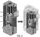
- FIG. 3 illustrates calibration of the monitoring system 200, according to some embodiments of this disclosure.
- calibration of the monitoring system 200 is performed through the use of the vibration sensor 210 or the microphone 220, or both, in conjunction with the conventional portable device 310 or other measurement device used manually.
- the portable device 310 may be placed on the floor of the elevator car 103 as usual. Because use of the portable device 310 is well-known, there may exist established thresholds indicating acceptable measurements by the portable device.
- the portable device 310 may take measurements during movement of the elevator car 103, while the vibration sensor 210 is also taking measurements or the microphone 220 is capturing audio, or both.
- one or more transformations may be established to map sensor data 260 of the vibration sensor 210 or the microphone 220, or both, to measurements output by the portable device 310.
- the sensor data 260 and the measurements of the portable device 310 may be transmitted to the cloud 250, where the analytics system 270 may determine the one or more transformations.
- the monitoring system 200 may be trained offline.
- the analytics system 270 utilizes the resulting one or more transformations to analyze continuous ride quality remotely, based on current sensor data 260.
- FIG. 4 is a flow diagram of a method of monitoring continuous ride quality, according to some embodiments of this disclosure. It will be understood that this method 400 is an illustrative example and does not limit the various embodiments of this disclosure.
- the monitoring system 200 is installed in an elevator system 101. In some embodiments, this occurs during commissioning of the elevator system 101, but alternatively, the monitoring system 200 may be installed in an elevator system 101 after the elevator system 101 has entered into regular use. As discussed above, the positioning of various components of the monitoring system 200 may vary.
- the monitoring system 200 is initialized, which may include, for example, calibration or cognitive training.
- calibration may involve training the analytics system 270 to recognize various levels of ride quality by determining a transformation between measurements of the vibration sensor 210 or microphone 220 and measurements of the portable device 310. Additionally or alternatively, the analytics system may learn, via machine learning, to recognize levels of ride quality in sensor data 260.
- the monitoring system 200 continuously detects at least one of vibration data and audio data. This may occur without manual supervision. Further, the detection by each of the vibration sensor 210 and the microphone 220 need not occur at every moment. Rather, each of the vibration sensor 210 and the microphone 220 may be associated with a respective set of trigger events, which cause them to begin detecting and generating a respective data stream, and a respective set of sleep events, which cause them to stop detecting and thus stop generating a respective data stream.
- the processing unit 230 of the monitoring system 200 receives a respective data stream from each of the vibration sensor 210 and the microphone 220.
- the processing unit 230 preprocesses the data streams, which results in sensor data 260.
- the processing unit 230 transmits the sensor data 260 through a communication device 240 to the cloud 250.
- the analytics system 270 analyzes the sensor data 260 as it is received to thereby monitor the continuous ride quality remotely and in real time.
- the analytics system 270 determines whether the sensor data 260 received meets a threshold quality. If the threshold quality is met, then at block 445, the analytics system 270 continues receiving sensor data 260 and analyzing the sensor data 260 as it arrives. If the threshold quality is not met, however, then at block 450, the analytics system 270 additionally issues an alert indicating that maintenance may be required. In either case, the analytics system 270 may continue to monitor the elevator system 101 by analyzing the sensor data 260 as it is received.
- ride quality of an elevator system 101 or group of elevator systems 101 can be monitored continuously and remotely, regardless of whether a technician is present.
- this remote monitoring occurs in real time and can therefore be used to initiate maintenance visits on an as-needed basis.
- embodiments can be in the form of processing unit-implemented processes and devices for practicing those processes, such as a processing unit.
- Embodiments can also be in the form of computer program code containing instructions embodied in tangible media, such as network cloud storage, SD cards, flash drives, floppy diskettes, CD ROMs, hard drives, or any other computer-readable storage medium, wherein, when the computer program code is loaded into and executed by a computer, the computer becomes a device for practicing the embodiments.
- Embodiments can also be in the form of computer program code, for example, whether stored in a storage medium, loaded into and/or executed by a computer, or transmitted over some transmission medium, loaded into and/or executed by a computer, or transmitted over some transmission medium, such as over electrical wiring or cabling, through fiber optics, or via electromagnetic radiation, wherein, when the computer program code is loaded into an executed by a computer, the computer becomes an device for practicing the embodiments.
- the computer program code segments configure the microprocessing unit to create specific logic circuits.
Landscapes
- Engineering & Computer Science (AREA)
- Automation & Control Theory (AREA)
- Computer Networks & Wireless Communication (AREA)
- Indicating And Signalling Devices For Elevators (AREA)
Applications Claiming Priority (1)
| Application Number | Priority Date | Filing Date | Title |
|---|---|---|---|
| US16/165,856 US20200122967A1 (en) | 2018-10-19 | 2018-10-19 | Continuous quality monitoring of a conveyance system |
Publications (1)
| Publication Number | Publication Date |
|---|---|
| EP3640188A1 true EP3640188A1 (de) | 2020-04-22 |
Family
ID=68296318
Family Applications (1)
| Application Number | Title | Priority Date | Filing Date |
|---|---|---|---|
| EP19204438.6A Pending EP3640188A1 (de) | 2018-10-19 | 2019-10-21 | Kontinuierliche qualitätsüberwachung eines fördersystems |
Country Status (4)
| Country | Link |
|---|---|
| US (1) | US20200122967A1 (de) |
| EP (1) | EP3640188A1 (de) |
| CN (1) | CN111071885A (de) |
| AU (1) | AU2019250144A1 (de) |
Cited By (2)
| Publication number | Priority date | Publication date | Assignee | Title |
|---|---|---|---|---|
| US20200109027A1 (en) * | 2018-10-04 | 2020-04-09 | Otis Elevator Company | Elevator car position determination |
| WO2022223869A1 (en) * | 2021-04-21 | 2022-10-27 | Kone Corporation | An elevator monitoring solution for an elevator system |
Families Citing this family (1)
| Publication number | Priority date | Publication date | Assignee | Title |
|---|---|---|---|---|
| EP3978411A1 (de) * | 2020-10-02 | 2022-04-06 | KONE Corporation | Zustandsüberwachung eines aufzugs |
Citations (3)
| Publication number | Priority date | Publication date | Assignee | Title |
|---|---|---|---|---|
| JP2005247470A (ja) * | 2004-03-02 | 2005-09-15 | Toshiba Elevator Co Ltd | 昇降機の計測装置 |
| EP3190075A1 (de) * | 2016-12-12 | 2017-07-12 | Lift Technology GmbH | Überwachungseinheit für die überwachung eines aufzugs |
| US20180044134A1 (en) * | 2015-02-24 | 2018-02-15 | Otis Elevator Company | System and method of measuring and diagnosing ride quality of an elevator system |
Family Cites Families (15)
| Publication number | Priority date | Publication date | Assignee | Title |
|---|---|---|---|---|
| FI117432B (fi) * | 2002-02-05 | 2006-10-13 | Kone Corp | Menetelmä ja järjestely hissin kaukovalvontaan |
| JP2009007143A (ja) * | 2007-06-29 | 2009-01-15 | Mitsubishi Electric Building Techno Service Co Ltd | 運行データ収集装置 |
| CN101959785B (zh) * | 2008-03-06 | 2014-04-30 | 因温特奥股份公司 | 电梯设备以及维修这种电梯设备的方法 |
| CN201406235Y (zh) * | 2009-03-27 | 2010-02-17 | 北京市朝阳区特种设备检测所 | 电梯动态智能监控装置 |
| EP2336070B1 (de) * | 2009-12-18 | 2016-08-03 | ThyssenKrupp Aufzugswerke GmbH | Verfahren zur Ferndiagnose einer Aufzuganlage und Aufzuganlage zur Durchführung des Verfahrens |
| US8893858B2 (en) * | 2010-06-29 | 2014-11-25 | Empire Technology Development Llc | Method and system for determining safety of elevator |
| EP2604564A1 (de) * | 2011-12-14 | 2013-06-19 | Inventio AG | Fehlerdiagnose einer Aufzuganlage und seiner Komponenten mittels Sensor |
| CN102556792B (zh) * | 2012-03-13 | 2014-07-16 | 杭州市特种设备检测院 | 电梯运行性能在线分析仪及在线分析方法 |
| CN102897623B (zh) * | 2012-09-24 | 2014-12-17 | 浙江大学 | 基于Internet的电梯运行质量远程检测系统和方法 |
| KR102488932B1 (ko) * | 2014-09-11 | 2023-01-16 | 오티스 엘리베이터 컴파니 | 진동-기반 승강기 인장 부재 마모 및 수명 모니터링 시스템 |
| MX2017015447A (es) * | 2015-06-02 | 2018-03-08 | Inventio Ag | Monitoreo de un sistema de transporte. |
| CN205472067U (zh) * | 2016-01-29 | 2016-08-17 | 天津市英航科技有限公司 | 楼宇内电梯噪音信号检测监控系统 |
| KR101915384B1 (ko) * | 2017-02-16 | 2018-11-06 | 한국승강기안전공단 | 엘리베이터 및 에스컬레이터의 소음진동 및 주행속도 측정시스템 |
| CN110418760B (zh) * | 2017-03-15 | 2021-03-02 | 因温特奥股份公司 | 用于监控人员运送设备中的运行参数的方法和装置 |
| US20200071125A1 (en) * | 2018-08-31 | 2020-03-05 | Lift AI, LLC | Camera system for remotely monitoring an elevator controller |
-
2018
- 2018-10-19 US US16/165,856 patent/US20200122967A1/en active Pending
-
2019
- 2019-10-16 AU AU2019250144A patent/AU2019250144A1/en active Pending
- 2019-10-18 CN CN201910993945.0A patent/CN111071885A/zh active Pending
- 2019-10-21 EP EP19204438.6A patent/EP3640188A1/de active Pending
Patent Citations (3)
| Publication number | Priority date | Publication date | Assignee | Title |
|---|---|---|---|---|
| JP2005247470A (ja) * | 2004-03-02 | 2005-09-15 | Toshiba Elevator Co Ltd | 昇降機の計測装置 |
| US20180044134A1 (en) * | 2015-02-24 | 2018-02-15 | Otis Elevator Company | System and method of measuring and diagnosing ride quality of an elevator system |
| EP3190075A1 (de) * | 2016-12-12 | 2017-07-12 | Lift Technology GmbH | Überwachungseinheit für die überwachung eines aufzugs |
Cited By (2)
| Publication number | Priority date | Publication date | Assignee | Title |
|---|---|---|---|---|
| US20200109027A1 (en) * | 2018-10-04 | 2020-04-09 | Otis Elevator Company | Elevator car position determination |
| WO2022223869A1 (en) * | 2021-04-21 | 2022-10-27 | Kone Corporation | An elevator monitoring solution for an elevator system |
Also Published As
| Publication number | Publication date |
|---|---|
| AU2019250144A1 (en) | 2020-05-07 |
| US20200122967A1 (en) | 2020-04-23 |
| CN111071885A (zh) | 2020-04-28 |
Similar Documents
| Publication | Publication Date | Title |
|---|---|---|
| CN110606417B (zh) | 电梯传感器系统楼层映射 | |
| CN111924678B (zh) | 超出加速度最大值的电梯健康状况排序 | |
| US11724910B2 (en) | Monitoring of conveyance system vibratory signatures | |
| EP3640188A1 (de) | Kontinuierliche qualitätsüberwachung eines fördersystems | |
| US11524869B2 (en) | Method for monitoring an elevator system | |
| AU2012384009A1 (en) | Position and load measurement system for an elevator | |
| US10827238B2 (en) | Elevator door sensor integrated with a long range communication gateway | |
| EP3640178B1 (de) | Bestimmung der position einer aufzugskabine mittels vibration | |
| EP3628624B1 (de) | Sensorbasierte abschaltdetektion eines aufzugssystems | |
| CN111348498B (zh) | 用于电梯监测的虚拟传感器 | |
| JP6997680B2 (ja) | エレベーター異常監視システム及びエレベーター異常監視方法 | |
| US20220112051A1 (en) | Monitoring system for conveyance system | |
| US11964846B2 (en) | Elevator location determination based on car vibrations or accelerations | |
| CN111847161A (zh) | 电梯井分布式健康水平 | |
| CN113213290B (zh) | 使用声音和视频对电梯门性能进行测量和诊断 | |
| CN111320047B (zh) | 基于井道进入检测的安全系统 | |
| US20220119224A1 (en) | Elevator monitoring system | |
| CN112209189B (zh) | 客户行为驱动的预测性维护 | |
| CN112660948A (zh) | 使用轿厢内相机的基于电梯状况的维护 | |
| US20200055691A1 (en) | Last-minute hall call request to a departing cab using gesture | |
| US20220112050A1 (en) | Elevator system floor height mapping | |
| CN117043093A (zh) | 使用数字孪生来确定电梯维护需求的方法和系统 |
Legal Events
| Date | Code | Title | Description |
|---|---|---|---|
| PUAI | Public reference made under article 153(3) epc to a published international application that has entered the european phase |
Free format text: ORIGINAL CODE: 0009012 |
|
| STAA | Information on the status of an ep patent application or granted ep patent |
Free format text: STATUS: THE APPLICATION HAS BEEN PUBLISHED |
|
| AK | Designated contracting states |
Kind code of ref document: A1 Designated state(s): AL AT BE BG CH CY CZ DE DK EE ES FI FR GB GR HR HU IE IS IT LI LT LU LV MC MK MT NL NO PL PT RO RS SE SI SK SM TR |
|
| AX | Request for extension of the european patent |
Extension state: BA ME |
|
| STAA | Information on the status of an ep patent application or granted ep patent |
Free format text: STATUS: REQUEST FOR EXAMINATION WAS MADE |
|
| 17P | Request for examination filed |
Effective date: 20201022 |
|
| RBV | Designated contracting states (corrected) |
Designated state(s): AL AT BE BG CH CY CZ DE DK EE ES FI FR GB GR HR HU IE IS IT LI LT LU LV MC MK MT NL NO PL PT RO RS SE SI SK SM TR |
|
| STAA | Information on the status of an ep patent application or granted ep patent |
Free format text: STATUS: EXAMINATION IS IN PROGRESS |
|
| 17Q | First examination report despatched |
Effective date: 20210809 |