EP3640188A1 - Continuous quality monitoring of a conveyance system - Google Patents
Continuous quality monitoring of a conveyance system Download PDFInfo
- Publication number
- EP3640188A1 EP3640188A1 EP19204438.6A EP19204438A EP3640188A1 EP 3640188 A1 EP3640188 A1 EP 3640188A1 EP 19204438 A EP19204438 A EP 19204438A EP 3640188 A1 EP3640188 A1 EP 3640188A1
- Authority
- EP
- European Patent Office
- Prior art keywords
- data
- conveyance system
- vibration
- sensor
- microphone
- Prior art date
- Legal status (The legal status is an assumption and is not a legal conclusion. Google has not performed a legal analysis and makes no representation as to the accuracy of the status listed.)
- Pending
Links
Images


Classifications
-
- B—PERFORMING OPERATIONS; TRANSPORTING
- B66—HOISTING; LIFTING; HAULING
- B66B—ELEVATORS; ESCALATORS OR MOVING WALKWAYS
- B66B5/00—Applications of checking, fault-correcting, or safety devices in elevators
- B66B5/0006—Monitoring devices or performance analysers
-
- B—PERFORMING OPERATIONS; TRANSPORTING
- B66—HOISTING; LIFTING; HAULING
- B66B—ELEVATORS; ESCALATORS OR MOVING WALKWAYS
- B66B5/00—Applications of checking, fault-correcting, or safety devices in elevators
- B66B5/0006—Monitoring devices or performance analysers
- B66B5/0018—Devices monitoring the operating condition of the elevator system
- B66B5/0025—Devices monitoring the operating condition of the elevator system for maintenance or repair
-
- B—PERFORMING OPERATIONS; TRANSPORTING
- B66—HOISTING; LIFTING; HAULING
- B66B—ELEVATORS; ESCALATORS OR MOVING WALKWAYS
- B66B1/00—Control systems of elevators in general
- B66B1/24—Control systems with regulation, i.e. with retroactive action, for influencing travelling speed, acceleration, or deceleration
- B66B1/28—Control systems with regulation, i.e. with retroactive action, for influencing travelling speed, acceleration, or deceleration electrical
-
- B—PERFORMING OPERATIONS; TRANSPORTING
- B66—HOISTING; LIFTING; HAULING
- B66B—ELEVATORS; ESCALATORS OR MOVING WALKWAYS
- B66B1/00—Control systems of elevators in general
- B66B1/34—Details, e.g. call counting devices, data transmission from car to control system, devices giving information to the control system
- B66B1/3415—Control system configuration and the data transmission or communication within the control system
- B66B1/3446—Data transmission or communication within the control system
- B66B1/3461—Data transmission or communication within the control system between the elevator control system and remote or mobile stations
-
- B—PERFORMING OPERATIONS; TRANSPORTING
- B66—HOISTING; LIFTING; HAULING
- B66B—ELEVATORS; ESCALATORS OR MOVING WALKWAYS
- B66B5/00—Applications of checking, fault-correcting, or safety devices in elevators
- B66B5/0006—Monitoring devices or performance analysers
- B66B5/0037—Performance analysers
-
- B—PERFORMING OPERATIONS; TRANSPORTING
- B66—HOISTING; LIFTING; HAULING
- B66B—ELEVATORS; ESCALATORS OR MOVING WALKWAYS
- B66B5/00—Applications of checking, fault-correcting, or safety devices in elevators
- B66B5/0087—Devices facilitating maintenance, repair or inspection tasks
Definitions
- Exemplary embodiments pertain to the art of conveyance systems and, more particularly, to continuous quality monitoring of an elevator system or other conveyance system.
- Ride quality of elevator systems is one of the main metrics of passenger comfort in an elevator car.
- ride quality is measured during commissioning and during maintenance.
- a technician places a portable device on the floor of the elevator car.
- the portable device takes measurements related to the ride quality. These measurements are readable by the technician to determine the quality of the ride at that time.
- a monitoring system includes one or more detection devices, a communication device, and an analytics system.
- the one or more detection devices generate, at a conveyance system, one or more data streams describing the ride of the conveyance system, where the data streams include at least one of vibration data and audio data.
- the communication device transmits sensor data based on the one or more data streams.
- the analytics system at least a part of which is remote from the conveyance system, receives the sensor data from the communication device and, based on the sensor data, determines a ride quality of the conveyance system based on the sensor data. According to one or more embodiments, the analytics system determines the ride quality in real time.
- a monitoring method includes generating, at a conveyance system, one or more data streams describing the ride of a conveyance system, where the data streams include at least one of vibration data and audio data.
- Sensor data based on the one or more data streams is transmitted to an analytics system remote from the conveyance system.
- a ride quality of the conveyance system is determined (e.g. in real time), based on the sensor data.
- a computer-program product for monitoring a conveyance system includes a computer-readable storage medium having program instructions embodied therewith.
- the program instructions are executable by a processing unit to cause the processing unit to perform a method.
- the method includes generating, at a conveyance system, one or more data streams describing the ride of the conveyance system, where the data streams include at least one of vibration data and audio data.
- sensor data based on the one or more data streams is transmitted to an analytics system remote from the conveyance system.
- a ride quality of the conveyance system is determined (e.g. in real time), based on the sensor data.
- the one or more data streams generated at the conveyance system include vibration data generated by a vibration sensor or audio data captured by a microphone, or both.
- the conveyance system is an elevator system.
- the vibration sensor detects a trigger event and generates the vibration data responsive to the trigger event.
- the microphone detects a trigger event and captures the audio data responsive to the trigger event.
- local preprocessing is performed, at the conveyance system, on the one or more data streams to generate the sensor data.
- the audio data captured by the microphone includes audio during a run of the conveyance system as well as audio of a run of a second conveyance system.
- calibration is performed.
- the calibration includes determining one or more transformations between the sensor data and measurements taken by a measurement device.
- the analytics system learns, by machine learning based on historical sensor data, to recognize the ride quality of the conveyance system.
- the analytics system automatically performs a remedial action responsive to the ride quality of the conveyance system.
- inventions of the present disclosure include remote monitoring of the continuous ride quality of an conveyance system, and optionally in real time, without the need for a technician to be present at the conveyance system.
- an alert can be generated to dispatch a technician if performance of the conveyance system is sufficiently degraded.
- the technician can be alerted to likely problems and can therefore arrive prepared to make the expected repairs.
- FIG. 1 is a perspective view of an elevator system 101 including an elevator car 103, a counterweight 105, a tension member 107, a guide rail 109, a machine 111, a position reference system 113, and a controller 115.
- the elevator car 103 and counterweight 105 are connected to each other by the tension member 107.
- the tension member 107 may include or be configured as, for example, ropes, steel cables, and/or coated-steel belts.
- the counterweight 105 is configured to balance a load of the elevator car 103 and is configured to facilitate movement of the elevator car 103 concurrently and in an opposite direction with respect to the counterweight 105 within an elevator hoistway 117 and along the guide rail 109.
- the tension member 107 engages the machine 111, which is part of an overhead structure of the elevator system 101.
- the machine 111 is configured to control movement between the elevator car 103 and the counterweight 105.
- the position reference system 113 may be mounted on a fixed part at the top of the elevator hoistway 117, such as on a support or guide rail, and may be configured to provide position signals related to a position of the elevator car 103 within the elevator hoistway 117. In other embodiments, the position reference system 113 may be directly mounted to a moving component of the machine 111, or may be located in other positions and/or configurations as known in the art.
- the position reference system 113 can be any device or mechanism for monitoring a position of an elevator car and/or counter weight, as known in the art.
- the position reference system 113 can be an encoder, sensor, or other system and can include velocity sensing, absolute position sensing, etc., as will be appreciated by those of skill in the art.
- the controller 115 is located, as shown, in a controller room 121 of the elevator hoistway 117 and is configured to control the operation of the elevator system 101, and particularly the elevator car 103.
- the controller 115 may provide drive signals to the machine 111 to control the acceleration, deceleration, leveling, stopping, etc. of the elevator car 103.
- the controller 115 may also be configured to receive position signals from the position reference system 113 or any other desired position reference device.
- the elevator car 103 may stop at one or more landings 125 as controlled by the controller 115.
- the controller 115 can be located and/or configured in other locations or positions within the elevator system 101. In one embodiment, the controller may be located remotely or in the cloud.
- the machine 111 may include a motor or similar driving mechanism.
- the machine 111 is configured to include an electrically driven motor.
- the power supply for the motor may be any power source, including a power grid, which, in combination with other components, is supplied to the motor.
- the machine 111 may include a traction sheave that imparts force to tension member 107 to move the elevator car 103 within elevator hoistway 117.
- elevator systems 101 that employ other methods and mechanisms of moving an elevator car within an elevator hoistway 117 may employ embodiments of the present disclosure.
- embodiments may be employed in ropeless elevator systems 101 using a linear motor to impart motion to an elevator car 103.
- An embodiment may also be employed in a ropeless elevator system 101 using a hydraulic lift to impart motion to an elevator car 103.
- FIG. 1 is merely a non-limiting example presented for illustrative and explanatory purposes.
- FIG. 2 is a diagram of a monitoring system 200 for monitoring the continuous ride quality of a conveyance system, such as an elevator system 101, according to some embodiments of this disclosure.
- a conveyance system such as an elevator system 101
- FIG. 2 describes in detail application of the monitoring system 200 to an elevator system 101, it will be understood by one skilled in the art that various embodiments may be applicable to escalators or other conveyance systems.
- the monitoring system 200 includes one or more detection devices, such as a vibration sensor 210 and a microphone 220.
- the vibration sensor 210 or the microphone 220, or both are connected to a processing unit 230, which receives measurements from the connected vibration sensor 210 or microphone 220, or both.
- the processing unit 230 may be connected to a cloud 250.
- the processing unit 230 may thus transmit sensor data 260 to the cloud 250, where an analytics system 270 may perform analytics to determine continuous ride quality and thereby monitor continuous ride quality remotely.
- FIG. 2 shows the vibration sensor 210, the microphone 220, the processing unit 230, and the communication device 240 positioned together, this is for illustrative purposes only. When both the vibration sensor 210 and the microphone 220 are used, these may be separate devices or may be integrated together into a single detection device. Additionally, each of the processing unit 230 and the communication device 240 may be a distinct device as well. Further, these various components need not be positioned together in the elevator system 101 but, rather, may be distributed throughout the elevator system 101, as will be discussed further below. Thus, although FIG. 2 illustrates a single device as the vibration sensor 210, the microphone 220, the processing unit 230, and the communication device 240, it will be understood by one skilled in the art that the monitoring system 200 may include one or multiple devices for these purposes.
- the vibration sensor 210, the microphone 220, the processing unit 230, and the communication device 240 may be positioned above the elevator car 103.
- the vibration sensor 210 may be built into a wall of the elevator car 103 or affixed on a door header of the elevator car 103.
- the microphone may be integrated into the elevator car 103 as part of an in-car telecommunications systems, which may be useable for additional purposes other than those described herein.
- the processing unit 230 may be positioned so as to enable a connection with each of the vibration sensor 210 and the microphone 220, and the communication device 240 may be positioned so as to enable a connection with the processing unit 230.
- Each of the vibration sensor 210, the microphone 220, the processing unit 230, and the communication device 240 may be affixed to or integrated with the elevator system 101 or may be placed in or on aspects of the elevator system without being affixed.
- a portable device is used during commissioning and during maintenance to test the ride quality of an elevator system at the time of such commissioning or maintenance.
- the events of commissioning and maintenance are short-term, and thus the testing performed at those times is not sufficient to obtain a full picture of the ride quality.
- ride quality can be monitored on a continuous basis in real time.
- the vibration sensor 210 may have higher fidelity than a conventional device used to measure ride quality, the measurements taken may be more reliable.
- further analytics may be performed in the cloud 250, the ride quality can be monitored and analyzed remotely, with various passenger volumes.
- the vibration sensor 210 is an accelerometer, such as a three-axis accelerometer.
- the vibration sensor 210 may detect vibrations in three dimensions.
- the vibration sensor 210 may detect vibrations in one or two dimensions.
- multiple vibration sensors 210 may be used.
- the vibration sensor 210 may output a data stream of vibration data, which includes measurements that describe vibrations detected during an elevator run of the elevator system 101.
- the vibration sensor 210 may be in communication with the processing unit 230 and may thus transmit that data stream to the processing unit 230.
- the vibration sensor 210 may remain with the elevator system 101 regardless of whether a technician is present. Specifically, the vibration sensor 210 may stay with the elevator system 101 continuously from installation until removal, which may be days, months, or years later. During that time, the vibration sensor 210 may continue to measure vibrations of the elevator car 103. Additionally, the vibration sensor 210 may continue to deliver detected measurements to the processing unit 230.
- the vibration sensor 210 need not detect vibrations all the time. Rather, the vibration sensor 210 may be in either sleep mode or active mode at a given time, such that the vibration sensor 210 measures vibrations during active mode but not during sleep mode.
- the active mode may be triggered responsive to a set of one or more trigger events, where the existence of at least one trigger event causes the vibration sensor 210 to switch to active mode.
- a trigger event may be the presence of at least one person inside the elevator car.
- a motion sensor or other device for detecting presence may be in communication with the vibration sensor 210, or a motion sensor or other presence detector may be in communication with the controller 115, which may communicate information as needed to the vibration sensor 210.
- the vibration sensor 210 may be switched to active mode when a trigger event occurs.
- trigger events may include one or more of the following: movement of the elevator car 103, which may be detected by the controller 115; or the elevator doors being closed, which may also be detected by the controller 115.
- the vibration sensor 210 may return to sleep mode responsive to a set of one or more sleep events, where the existence of at least one of such sleep events may cause the vibration sensor 210 to switch into sleep mode.
- Sleep events may include one or more of the following, for example: passage of a predetermined period of time after the last trigger event occurred; having reached a landing, which may be detected by the controller 115; or the elevator doors being open, which may be detected by the controller 115.
- Detection of a trigger event or a sleep event may be implemented in various ways, such as connecting a sensor of the trigger events and the sleep events to the processing unit 230 or to the controller 115, either of which may activate or deactivate the vibration sensor 210 as needed.
- the microphone 220 captures audio associated with movement of the elevator car 103 and, specifically, movement during an elevator run. Generally, this can be useful because a typical elevator ride is relatively quiet without unexpected noises, and the sound of the ride typically falls within an expected range.
- the microphone 220 may be positioned inside the elevator car, on top of the elevator car 103, or elsewhere in a position where the microphone 220 is capable of catching sounds emitted by movement of the elevator car 103.
- the microphone 220 may output a data stream of audio data representing the audio captured.
- the microphone 220 may be in communication with the processing unit 230 and may thus transmit this data stream to the processing unit 230.
- the audio captured may relate to not only the elevator system 101 in which the microphone is positioned, but also to one or more other nearby elevator systems 101.
- the microphone when positioned over the elevator car 103, the microphone is not isolated from background noise caused by nearby elevator systems 101 within the range of the microphone 220, and thus the microphone's output relates to those nearby elevator systems 101 as well.
- a group of two or more elevator systems 101 may be positioned nearby one another, perhaps sharing an elevator bay, and perhaps having connected or nearby elevator shafts.
- a microphone 220 positioned on top of the elevator car 103 of one of such elevator systems 101 may pick up audio representing the movements of the other elevator cars 103. This can be advantageous because, in some embodiments, a nearby elevator system 101 can be monitored by the monitoring system 200 without itself being outfitted with a microphone 220.
- the microphone 220 need not capture audio all the time. Rather, the microphone 220 may be in either sleep mode or active mode at a given time, such that the microphone 220 captures audio during its active mode but not during its sleep mode.
- the active mode may be triggered responsive to a trigger event
- the sleep mode may be triggered responsive to a sleep event.
- a sleep event may be the presence of at least one person inside the elevator car. When passengers are present in the elevator car 103, the microphone 220 would pick up audio created by those passengers, and thus, some embodiments capture audio only when the elevator car 103 is empty.
- a motion sensor or other device for detecting presence may be in communication with the microphone 220, or a motion sensor or other presence detector may be in communication with the controller 115, which may communicate presence as needed to the microphone 220.
- a trigger event may be the detection of no passengers present in the elevator car 103, and thus, the microphone 220 may resume capturing sounds when the elevator car 103 is empty.
- Detection of a trigger event or a sleep event may be implemented in various ways, such as connecting a sensor of the trigger events and the sleep events to the processing unit 230 or to the controller 115, either of which may activate or deactivate the microphone 220 as needed.
- both the vibration sensor 210 and the microphone 220 can operate at the same time, such that both vibrations and audio are measured simultaneously.
- both the vibration sensor 210 and the microphone 220 may be in communication with the processing unit 230.
- the processing unit 230 may receive a respective data stream from the vibration sensor 210, and if the monitoring system 200 includes a microphone 220, the processing unit 230 may receive a respective data stream from the microphone 220.
- the processing unit 230 may perform local preprocessing on each data stream received.
- the preprocessing may include one or more of the following: compression, removal of data within threshold values, or other operations.
- preprocessing can reduce network traffic from the processing unit 230 to the cloud 250 or can reduce or eliminate data likely to not be useful to the analytics system 270.
- the processing unit 230 may transmit sensor data 260 to the cloud 250, where sensor data 260 is the data received from the vibration sensor 210 or the microphone 220, or both. As discussed above, the processing unit 230 may perform preprocessing on the data streams in some embodiments, and thus the sensor data 260 transmitted to the cloud 250 need not be raw data from the data streams but, rather, may be the data resulting from preprocessing the data streams. However, if preprocessing is not performed, then the sensor data 260 may be the same as the data streams received by the processing unit 230. In some embodiments of this disclosure, the processing unit 230 transmits the sensor data 260 to the cloud 250 autonomously, for example, in real time, responsive to having received the data streams. Additionally or alternatively, the cloud 250 may request to receive the sensor data 260, and the processing unit 230 may thus transmit the sensor data 260 on demand.
- the processing unit 230 may be connected to the communication device 240.
- the connection between the processing unit 230 and the communication device 240 may be wired or wireless, such as, for example, ethernet, optical, wireless fidelity (WiFi), Zigbee, Zwave, Bluetooth, or any other known communications protocol.
- the communication device 240 may be a cellular gateway or other device capable of communicating with the cloud 250.
- the cloud 250 may include one or more nodes, each of which may be a computing device or a portion of computing device. Through these nodes, the cloud 250 may execute an analytics system 270, which may perform analytics on the sensor data 260 received from the processing unit 230. Generally, the analytics system 270 may seek to determine the ride quality of the elevator system 101, or the ride quality of the elevator system 101 and one or more nearby elevator systems 101.
- the analytics system 270 utilizes machine learning to analyze the sensor data 260 received from the processing unit 230.
- the analytics system 270 may include a cognitive engine that is trained on historical sensor data 260 associated with labels.
- This historical sensor data 260 may include data from the vibration sensor 210 or the microphone 220, or both.
- the labels may associate certain portions of the historical sensor data 260 with respective ride qualities, such as a specific levels of ride quality. For example, and not by way of limitation, if it is desired to group ride quality into three levels, then portions of the historical sensor data 260 may be labeled according to those three levels.
- the cognitive engine may thus be capable of receiving sensor data 260 and determining ride quality of the received sensor data 260. For example, given three levels of ride quality, the cognitive engine may be capable of identifying the ride quality level in each portion of sensor data 260.
- the analytics system 270 automatically performs remedial actions responsive to various levels of ride quality that are less than an established minimum level.
- a remedial action may be issuance of an alert, which may notify an owner or maintenance organization of the elevator system 101 that maintenance is needed.
- the analytics system 270 is capable of associating a portion of sensor data 260 with a quality level selected from a set of three quality levels, Level 1, Level 2, and Level 3, where an increasing level number indicates increasing quality, then Level 2 may be considered the minimum acceptable level.
- a quality of Level 2 may cause the analytics system 270 to issue an alert indicating that maintenance may be needed, while a quality of Level 1 may cause the analytics system 270 to issue an alert that maintenance is urgently needed.
- the maintenance organization can dispatch a technician to check the elevator system 101 in person.
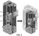
- FIG. 3 illustrates calibration of the monitoring system 200, according to some embodiments of this disclosure.
- calibration of the monitoring system 200 is performed through the use of the vibration sensor 210 or the microphone 220, or both, in conjunction with the conventional portable device 310 or other measurement device used manually.
- the portable device 310 may be placed on the floor of the elevator car 103 as usual. Because use of the portable device 310 is well-known, there may exist established thresholds indicating acceptable measurements by the portable device.
- the portable device 310 may take measurements during movement of the elevator car 103, while the vibration sensor 210 is also taking measurements or the microphone 220 is capturing audio, or both.
- one or more transformations may be established to map sensor data 260 of the vibration sensor 210 or the microphone 220, or both, to measurements output by the portable device 310.
- the sensor data 260 and the measurements of the portable device 310 may be transmitted to the cloud 250, where the analytics system 270 may determine the one or more transformations.
- the monitoring system 200 may be trained offline.
- the analytics system 270 utilizes the resulting one or more transformations to analyze continuous ride quality remotely, based on current sensor data 260.
- FIG. 4 is a flow diagram of a method of monitoring continuous ride quality, according to some embodiments of this disclosure. It will be understood that this method 400 is an illustrative example and does not limit the various embodiments of this disclosure.
- the monitoring system 200 is installed in an elevator system 101. In some embodiments, this occurs during commissioning of the elevator system 101, but alternatively, the monitoring system 200 may be installed in an elevator system 101 after the elevator system 101 has entered into regular use. As discussed above, the positioning of various components of the monitoring system 200 may vary.
- the monitoring system 200 is initialized, which may include, for example, calibration or cognitive training.
- calibration may involve training the analytics system 270 to recognize various levels of ride quality by determining a transformation between measurements of the vibration sensor 210 or microphone 220 and measurements of the portable device 310. Additionally or alternatively, the analytics system may learn, via machine learning, to recognize levels of ride quality in sensor data 260.
- the monitoring system 200 continuously detects at least one of vibration data and audio data. This may occur without manual supervision. Further, the detection by each of the vibration sensor 210 and the microphone 220 need not occur at every moment. Rather, each of the vibration sensor 210 and the microphone 220 may be associated with a respective set of trigger events, which cause them to begin detecting and generating a respective data stream, and a respective set of sleep events, which cause them to stop detecting and thus stop generating a respective data stream.
- the processing unit 230 of the monitoring system 200 receives a respective data stream from each of the vibration sensor 210 and the microphone 220.
- the processing unit 230 preprocesses the data streams, which results in sensor data 260.
- the processing unit 230 transmits the sensor data 260 through a communication device 240 to the cloud 250.
- the analytics system 270 analyzes the sensor data 260 as it is received to thereby monitor the continuous ride quality remotely and in real time.
- the analytics system 270 determines whether the sensor data 260 received meets a threshold quality. If the threshold quality is met, then at block 445, the analytics system 270 continues receiving sensor data 260 and analyzing the sensor data 260 as it arrives. If the threshold quality is not met, however, then at block 450, the analytics system 270 additionally issues an alert indicating that maintenance may be required. In either case, the analytics system 270 may continue to monitor the elevator system 101 by analyzing the sensor data 260 as it is received.
- ride quality of an elevator system 101 or group of elevator systems 101 can be monitored continuously and remotely, regardless of whether a technician is present.
- this remote monitoring occurs in real time and can therefore be used to initiate maintenance visits on an as-needed basis.
- embodiments can be in the form of processing unit-implemented processes and devices for practicing those processes, such as a processing unit.
- Embodiments can also be in the form of computer program code containing instructions embodied in tangible media, such as network cloud storage, SD cards, flash drives, floppy diskettes, CD ROMs, hard drives, or any other computer-readable storage medium, wherein, when the computer program code is loaded into and executed by a computer, the computer becomes a device for practicing the embodiments.
- Embodiments can also be in the form of computer program code, for example, whether stored in a storage medium, loaded into and/or executed by a computer, or transmitted over some transmission medium, loaded into and/or executed by a computer, or transmitted over some transmission medium, such as over electrical wiring or cabling, through fiber optics, or via electromagnetic radiation, wherein, when the computer program code is loaded into an executed by a computer, the computer becomes an device for practicing the embodiments.
- the computer program code segments configure the microprocessing unit to create specific logic circuits.
Landscapes
- Engineering & Computer Science (AREA)
- Automation & Control Theory (AREA)
- Computer Networks & Wireless Communication (AREA)
- Indicating And Signalling Devices For Elevators (AREA)
Abstract
Description
- Exemplary embodiments pertain to the art of conveyance systems and, more particularly, to continuous quality monitoring of an elevator system or other conveyance system.
- Ride quality of elevator systems is one of the main metrics of passenger comfort in an elevator car. Currently, ride quality is measured during commissioning and during maintenance. A technician places a portable device on the floor of the elevator car. The portable device takes measurements related to the ride quality. These measurements are readable by the technician to determine the quality of the ride at that time.
- According to an aspect of the present invention, a monitoring system includes one or more detection devices, a communication device, and an analytics system. The one or more detection devices generate, at a conveyance system, one or more data streams describing the ride of the conveyance system, where the data streams include at least one of vibration data and audio data. The communication device transmits sensor data based on the one or more data streams. The analytics system, at least a part of which is remote from the conveyance system, receives the sensor data from the communication device and, based on the sensor data, determines a ride quality of the conveyance system based on the sensor data. According to one or more embodiments, the analytics system determines the ride quality in real time.
- According to another aspect of the present invention, a monitoring method includes generating, at a conveyance system, one or more data streams describing the ride of a conveyance system, where the data streams include at least one of vibration data and audio data. Sensor data based on the one or more data streams is transmitted to an analytics system remote from the conveyance system. A ride quality of the conveyance system is determined (e.g. in real time), based on the sensor data.
- According to yet another aspect of the present invention, a computer-program product for monitoring a conveyance system includes a computer-readable storage medium having program instructions embodied therewith. The program instructions are executable by a processing unit to cause the processing unit to perform a method. The method includes generating, at a conveyance system, one or more data streams describing the ride of the conveyance system, where the data streams include at least one of vibration data and audio data. Further according to the method, sensor data based on the one or more data streams is transmitted to an analytics system remote from the conveyance system. A ride quality of the conveyance system is determined (e.g. in real time), based on the sensor data.
- In addition to one or more of the features described herein, in further embodiments, the one or more data streams generated at the conveyance system include vibration data generated by a vibration sensor or audio data captured by a microphone, or both.
- In addition to one or more of the features described herein, or as an alternative, in further embodiments, the conveyance system is an elevator system.
- In addition to one or more of the features described herein, or as an alternative, in further embodiments, the vibration sensor detects a trigger event and generates the vibration data responsive to the trigger event.
- In addition to one or more of the features described herein, or as an alternative, in further embodiments, the microphone detects a trigger event and captures the audio data responsive to the trigger event.
- In addition to one or more of the features described herein, or as an alternative, in further embodiments, local preprocessing is performed, at the conveyance system, on the one or more data streams to generate the sensor data.
- In addition to one or more of the features described herein, or as an alternative, in further embodiments, the audio data captured by the microphone includes audio during a run of the conveyance system as well as audio of a run of a second conveyance system.
- In addition to one or more of the features described herein, or as an alternative, in further embodiments, calibration is performed. The calibration includes determining one or more transformations between the sensor data and measurements taken by a measurement device.
- In addition to one or more of the features described herein, or as an alternative, in further embodiments, the analytics system learns, by machine learning based on historical sensor data, to recognize the ride quality of the conveyance system.
- In addition to one or more of the features described herein, or as an alternative, in further embodiments, the analytics system automatically performs a remedial action responsive to the ride quality of the conveyance system.
- Technical effects of embodiments of the present disclosure include remote monitoring of the continuous ride quality of an conveyance system, and optionally in real time, without the need for a technician to be present at the conveyance system. Thus, an alert can be generated to dispatch a technician if performance of the conveyance system is sufficiently degraded. Additionally, the technician can be alerted to likely problems and can therefore arrive prepared to make the expected repairs.
- The foregoing features and elements may be combined in various combinations without exclusivity, unless expressly indicated otherwise. These features and elements as well as the operation thereof will become more apparent in light of the following description and the accompanying drawings. It should be understood, however, that the following description and drawings are intended to be illustrative and explanatory in nature and non-limiting.
- The present disclosure is illustrated by way of example and not limited in the accompanying figures in which like reference numerals indicate similar elements.
-
FIG. 1 is a schematic illustration of an elevator system that may employ various embodiments of the present disclosure; -
FIG. 2 is a diagram of a monitoring system for monitoring the continuous ride quality of a conveyance system, such as an elevator system, according to some embodiments of the present disclosure; -
FIG. 3 illustrates calibration of the monitoring system, according to some embodiments of the present disclosure; and -
FIG. 4 is a flow diagram of a method of monitoring continuous ride quality, according to some embodiments of the present disclosure. - A detailed description of one or more embodiments of the disclosed apparatus and method are presented herein by way of exemplification and not limitation with reference to the Figures.
-
FIG. 1 is a perspective view of anelevator system 101 including anelevator car 103, acounterweight 105, atension member 107, aguide rail 109, amachine 111, aposition reference system 113, and acontroller 115. Theelevator car 103 andcounterweight 105 are connected to each other by thetension member 107. Thetension member 107 may include or be configured as, for example, ropes, steel cables, and/or coated-steel belts. Thecounterweight 105 is configured to balance a load of theelevator car 103 and is configured to facilitate movement of theelevator car 103 concurrently and in an opposite direction with respect to thecounterweight 105 within anelevator hoistway 117 and along theguide rail 109. - The
tension member 107 engages themachine 111, which is part of an overhead structure of theelevator system 101. Themachine 111 is configured to control movement between theelevator car 103 and thecounterweight 105. Theposition reference system 113 may be mounted on a fixed part at the top of theelevator hoistway 117, such as on a support or guide rail, and may be configured to provide position signals related to a position of theelevator car 103 within theelevator hoistway 117. In other embodiments, theposition reference system 113 may be directly mounted to a moving component of themachine 111, or may be located in other positions and/or configurations as known in the art. Theposition reference system 113 can be any device or mechanism for monitoring a position of an elevator car and/or counter weight, as known in the art. For example, without limitation, theposition reference system 113 can be an encoder, sensor, or other system and can include velocity sensing, absolute position sensing, etc., as will be appreciated by those of skill in the art. - The
controller 115 is located, as shown, in acontroller room 121 of theelevator hoistway 117 and is configured to control the operation of theelevator system 101, and particularly theelevator car 103. For example, thecontroller 115 may provide drive signals to themachine 111 to control the acceleration, deceleration, leveling, stopping, etc. of theelevator car 103. Thecontroller 115 may also be configured to receive position signals from theposition reference system 113 or any other desired position reference device. When moving up or down within theelevator hoistway 117 alongguide rail 109, theelevator car 103 may stop at one ormore landings 125 as controlled by thecontroller 115. Although shown in acontroller room 121, those of skill in the art will appreciate that thecontroller 115 can be located and/or configured in other locations or positions within theelevator system 101. In one embodiment, the controller may be located remotely or in the cloud. - The
machine 111 may include a motor or similar driving mechanism. In accordance with embodiments of the disclosure, themachine 111 is configured to include an electrically driven motor. The power supply for the motor may be any power source, including a power grid, which, in combination with other components, is supplied to the motor. Themachine 111 may include a traction sheave that imparts force totension member 107 to move theelevator car 103 withinelevator hoistway 117. - Although shown and described with a roping system as the
tension member 107,elevator systems 101 that employ other methods and mechanisms of moving an elevator car within anelevator hoistway 117 may employ embodiments of the present disclosure. For example, embodiments may be employed inropeless elevator systems 101 using a linear motor to impart motion to anelevator car 103. An embodiment may also be employed in aropeless elevator system 101 using a hydraulic lift to impart motion to anelevator car 103.FIG. 1 is merely a non-limiting example presented for illustrative and explanatory purposes. -
FIG. 2 is a diagram of amonitoring system 200 for monitoring the continuous ride quality of a conveyance system, such as anelevator system 101, according to some embodiments of this disclosure. Although this disclosure describes in detail application of themonitoring system 200 to anelevator system 101, it will be understood by one skilled in the art that various embodiments may be applicable to escalators or other conveyance systems. - In some embodiments, the
monitoring system 200 includes one or more detection devices, such as avibration sensor 210 and amicrophone 220. In some embodiments, thevibration sensor 210 or themicrophone 220, or both, are connected to aprocessing unit 230, which receives measurements from the connectedvibration sensor 210 ormicrophone 220, or both. Through a communication device 240, theprocessing unit 230 may be connected to acloud 250. Theprocessing unit 230 may thus transmit sensor data 260 to thecloud 250, where ananalytics system 270 may perform analytics to determine continuous ride quality and thereby monitor continuous ride quality remotely. - Although
FIG. 2 shows thevibration sensor 210, themicrophone 220, theprocessing unit 230, and the communication device 240 positioned together, this is for illustrative purposes only. When both thevibration sensor 210 and themicrophone 220 are used, these may be separate devices or may be integrated together into a single detection device. Additionally, each of theprocessing unit 230 and the communication device 240 may be a distinct device as well. Further, these various components need not be positioned together in theelevator system 101 but, rather, may be distributed throughout theelevator system 101, as will be discussed further below. Thus, althoughFIG. 2 illustrates a single device as thevibration sensor 210, themicrophone 220, theprocessing unit 230, and the communication device 240, it will be understood by one skilled in the art that themonitoring system 200 may include one or multiple devices for these purposes. - As shown in
FIG. 2 , thevibration sensor 210, themicrophone 220, theprocessing unit 230, and the communication device 240 may be positioned above theelevator car 103. However, other positions of themonitoring system 200 may also be used. For example, and not by way of limitation, thevibration sensor 210 may be built into a wall of theelevator car 103 or affixed on a door header of theelevator car 103. For further example, the microphone may be integrated into theelevator car 103 as part of an in-car telecommunications systems, which may be useable for additional purposes other than those described herein. Theprocessing unit 230 may be positioned so as to enable a connection with each of thevibration sensor 210 and themicrophone 220, and the communication device 240 may be positioned so as to enable a connection with theprocessing unit 230. Each of thevibration sensor 210, themicrophone 220, theprocessing unit 230, and the communication device 240 may be affixed to or integrated with theelevator system 101 or may be placed in or on aspects of the elevator system without being affixed. - As discussed above, conventionally, a portable device is used during commissioning and during maintenance to test the ride quality of an elevator system at the time of such commissioning or maintenance. However, the events of commissioning and maintenance are short-term, and thus the testing performed at those times is not sufficient to obtain a full picture of the ride quality. Additionally, because only a single person is typically involved with measuring the ride quality, no variation of passenger volumes is considered with conventional mechanisms. According to some embodiments of this disclosure, however, ride quality can be monitored on a continuous basis in real time. Further, because the
vibration sensor 210 may have higher fidelity than a conventional device used to measure ride quality, the measurements taken may be more reliable. Further, because further analytics may be performed in thecloud 250, the ride quality can be monitored and analyzed remotely, with various passenger volumes. - In some embodiments of this disclosure, the
vibration sensor 210 is an accelerometer, such as a three-axis accelerometer. Thus, thevibration sensor 210 may detect vibrations in three dimensions. In some embodiments, thevibration sensor 210 may detect vibrations in one or two dimensions. In some embodiments,multiple vibration sensors 210 may be used. Generally, thevibration sensor 210 may output a data stream of vibration data, which includes measurements that describe vibrations detected during an elevator run of theelevator system 101. Thevibration sensor 210 may be in communication with theprocessing unit 230 and may thus transmit that data stream to theprocessing unit 230. - In contrast to the conventional portable device, the
vibration sensor 210 may remain with theelevator system 101 regardless of whether a technician is present. Specifically, thevibration sensor 210 may stay with theelevator system 101 continuously from installation until removal, which may be days, months, or years later. During that time, thevibration sensor 210 may continue to measure vibrations of theelevator car 103. Additionally, thevibration sensor 210 may continue to deliver detected measurements to theprocessing unit 230. - In some embodiments of this disclosure, the
vibration sensor 210 need not detect vibrations all the time. Rather, thevibration sensor 210 may be in either sleep mode or active mode at a given time, such that thevibration sensor 210 measures vibrations during active mode but not during sleep mode. In such embodiments, the active mode may be triggered responsive to a set of one or more trigger events, where the existence of at least one trigger event causes thevibration sensor 210 to switch to active mode. For example, and not by way of limitation, a trigger event may be the presence of at least one person inside the elevator car. To this end, for instance, a motion sensor or other device for detecting presence may be in communication with thevibration sensor 210, or a motion sensor or other presence detector may be in communication with thecontroller 115, which may communicate information as needed to thevibration sensor 210. In this manner, thevibration sensor 210 may be switched to active mode when a trigger event occurs. For additional examples, trigger events may include one or more of the following: movement of theelevator car 103, which may be detected by thecontroller 115; or the elevator doors being closed, which may also be detected by thecontroller 115. - The
vibration sensor 210 may return to sleep mode responsive to a set of one or more sleep events, where the existence of at least one of such sleep events may cause thevibration sensor 210 to switch into sleep mode. Sleep events may include one or more of the following, for example: passage of a predetermined period of time after the last trigger event occurred; having reached a landing, which may be detected by thecontroller 115; or the elevator doors being open, which may be detected by thecontroller 115. Detection of a trigger event or a sleep event may be implemented in various ways, such as connecting a sensor of the trigger events and the sleep events to theprocessing unit 230 or to thecontroller 115, either of which may activate or deactivate thevibration sensor 210 as needed. - The
microphone 220 captures audio associated with movement of theelevator car 103 and, specifically, movement during an elevator run. Generally, this can be useful because a typical elevator ride is relatively quiet without unexpected noises, and the sound of the ride typically falls within an expected range. Themicrophone 220 may be positioned inside the elevator car, on top of theelevator car 103, or elsewhere in a position where themicrophone 220 is capable of catching sounds emitted by movement of theelevator car 103. Themicrophone 220 may output a data stream of audio data representing the audio captured. Themicrophone 220 may be in communication with theprocessing unit 230 and may thus transmit this data stream to theprocessing unit 230. - When the
microphone 220 is positioned on top of theelevator car 103, the audio captured may relate to not only theelevator system 101 in which the microphone is positioned, but also to one or more othernearby elevator systems 101. In other words, when positioned over theelevator car 103, the microphone is not isolated from background noise caused bynearby elevator systems 101 within the range of themicrophone 220, and thus the microphone's output relates to thosenearby elevator systems 101 as well. For instance, a group of two ormore elevator systems 101 may be positioned nearby one another, perhaps sharing an elevator bay, and perhaps having connected or nearby elevator shafts. In that case, amicrophone 220 positioned on top of theelevator car 103 of one ofsuch elevator systems 101 may pick up audio representing the movements of theother elevator cars 103. This can be advantageous because, in some embodiments, anearby elevator system 101 can be monitored by themonitoring system 200 without itself being outfitted with amicrophone 220. - In some embodiments of this disclosure, the
microphone 220 need not capture audio all the time. Rather, themicrophone 220 may be in either sleep mode or active mode at a given time, such that themicrophone 220 captures audio during its active mode but not during its sleep mode. In such embodiments, the active mode may be triggered responsive to a trigger event, and the sleep mode may be triggered responsive to a sleep event. For example, and not by way of limitation, a sleep event may be the presence of at least one person inside the elevator car. When passengers are present in theelevator car 103, themicrophone 220 would pick up audio created by those passengers, and thus, some embodiments capture audio only when theelevator car 103 is empty. To this end, for instance, a motion sensor or other device for detecting presence may be in communication with themicrophone 220, or a motion sensor or other presence detector may be in communication with thecontroller 115, which may communicate presence as needed to themicrophone 220. For another example, a trigger event may be the detection of no passengers present in theelevator car 103, and thus, themicrophone 220 may resume capturing sounds when theelevator car 103 is empty. Detection of a trigger event or a sleep event may be implemented in various ways, such as connecting a sensor of the trigger events and the sleep events to theprocessing unit 230 or to thecontroller 115, either of which may activate or deactivate themicrophone 220 as needed. - In some embodiments of this disclosure, both the
vibration sensor 210 and themicrophone 220 can operate at the same time, such that both vibrations and audio are measured simultaneously. As discussed above, both thevibration sensor 210 and themicrophone 220 may be in communication with theprocessing unit 230. Thus, if themonitoring system 200 includes avibration sensor 210, theprocessing unit 230 may receive a respective data stream from thevibration sensor 210, and if themonitoring system 200 includes amicrophone 220, theprocessing unit 230 may receive a respective data stream from themicrophone 220. - The
processing unit 230 may perform local preprocessing on each data stream received. For example, and not by way of limitation, the preprocessing may include one or more of the following: compression, removal of data within threshold values, or other operations. In some embodiments, preprocessing can reduce network traffic from theprocessing unit 230 to thecloud 250 or can reduce or eliminate data likely to not be useful to theanalytics system 270. - The
processing unit 230 may transmit sensor data 260 to thecloud 250, where sensor data 260 is the data received from thevibration sensor 210 or themicrophone 220, or both. As discussed above, theprocessing unit 230 may perform preprocessing on the data streams in some embodiments, and thus the sensor data 260 transmitted to thecloud 250 need not be raw data from the data streams but, rather, may be the data resulting from preprocessing the data streams. However, if preprocessing is not performed, then the sensor data 260 may be the same as the data streams received by theprocessing unit 230. In some embodiments of this disclosure, theprocessing unit 230 transmits the sensor data 260 to thecloud 250 autonomously, for example, in real time, responsive to having received the data streams. Additionally or alternatively, thecloud 250 may request to receive the sensor data 260, and theprocessing unit 230 may thus transmit the sensor data 260 on demand. - To enable transmission of the sensor data 260, the
processing unit 230 may be connected to the communication device 240. The connection between theprocessing unit 230 and the communication device 240 may be wired or wireless, such as, for example, ethernet, optical, wireless fidelity (WiFi), Zigbee, Zwave, Bluetooth, or any other known communications protocol. For example, and not by way of limitation, the communication device 240 may be a cellular gateway or other device capable of communicating with thecloud 250. - The
cloud 250 may include one or more nodes, each of which may be a computing device or a portion of computing device. Through these nodes, thecloud 250 may execute ananalytics system 270, which may perform analytics on the sensor data 260 received from theprocessing unit 230. Generally, theanalytics system 270 may seek to determine the ride quality of theelevator system 101, or the ride quality of theelevator system 101 and one or morenearby elevator systems 101. - In some embodiments of this disclosure, the
analytics system 270 utilizes machine learning to analyze the sensor data 260 received from theprocessing unit 230. For instance, theanalytics system 270 may include a cognitive engine that is trained on historical sensor data 260 associated with labels. This historical sensor data 260 may include data from thevibration sensor 210 or themicrophone 220, or both. Specifically, the labels may associate certain portions of the historical sensor data 260 with respective ride qualities, such as a specific levels of ride quality. For example, and not by way of limitation, if it is desired to group ride quality into three levels, then portions of the historical sensor data 260 may be labeled according to those three levels. After being trained, the cognitive engine may thus be capable of receiving sensor data 260 and determining ride quality of the received sensor data 260. For example, given three levels of ride quality, the cognitive engine may be capable of identifying the ride quality level in each portion of sensor data 260. - In some embodiments, the
analytics system 270 automatically performs remedial actions responsive to various levels of ride quality that are less than an established minimum level. For example, and not by way of limitation, a remedial action may be issuance of an alert, which may notify an owner or maintenance organization of theelevator system 101 that maintenance is needed. For example, and not by way of limitation, if theanalytics system 270 is capable of associating a portion of sensor data 260 with a quality level selected from a set of three quality levels, Level 1, Level 2, and Level 3, where an increasing level number indicates increasing quality, then Level 2 may be considered the minimum acceptable level. In that case, a quality of Level 2 may cause theanalytics system 270 to issue an alert indicating that maintenance may be needed, while a quality of Level 1 may cause theanalytics system 270 to issue an alert that maintenance is urgently needed. Upon being notified of the alert, the maintenance organization can dispatch a technician to check theelevator system 101 in person. Thus, rather than determining ride quality only when a technician is present, as is conventionally the case, embodiments of this disclosure enable ride quality to be monitored continuously and remotely. - In some embodiments of this disclosure, analysis performed by the
analytics system 270 may be facilitated by calibration.FIG. 3 illustrates calibration of themonitoring system 200, according to some embodiments of this disclosure. As shown inFIG. 3 , in some embodiments, calibration of themonitoring system 200 is performed through the use of thevibration sensor 210 or themicrophone 220, or both, in conjunction with the conventionalportable device 310 or other measurement device used manually. Although calibration is discussed as being performed with theportable device 310 herein, it will be understood that other measurement devices useable by a technician may be used during calibration as well. To perform calibration, theportable device 310 may be placed on the floor of theelevator car 103 as usual. Because use of theportable device 310 is well-known, there may exist established thresholds indicating acceptable measurements by the portable device. - During calibration, the
portable device 310 may take measurements during movement of theelevator car 103, while thevibration sensor 210 is also taking measurements or themicrophone 220 is capturing audio, or both. Through techniques known in the art, one or more transformations may be established to map sensor data 260 of thevibration sensor 210 or themicrophone 220, or both, to measurements output by theportable device 310. Specifically, for example, the sensor data 260 and the measurements of theportable device 310 may be transmitted to thecloud 250, where theanalytics system 270 may determine the one or more transformations. As such, because one or more acceptable ranges of measurements of theportable device 310 are known, it can be determined which measurements of thevibration sensor 210 or themicrophone 220, or both, represent an acceptable ride quality through the use of these one or more transformations. - Thus, in this manner, the
monitoring system 200 may be trained offline. Further, in some embodiments, theanalytics system 270 utilizes the resulting one or more transformations to analyze continuous ride quality remotely, based on current sensor data 260. -
FIG. 4 is a flow diagram of a method of monitoring continuous ride quality, according to some embodiments of this disclosure. It will be understood that thismethod 400 is an illustrative example and does not limit the various embodiments of this disclosure. - As shown in
FIG. 4 , atblock 405, themonitoring system 200 is installed in anelevator system 101. In some embodiments, this occurs during commissioning of theelevator system 101, but alternatively, themonitoring system 200 may be installed in anelevator system 101 after theelevator system 101 has entered into regular use. As discussed above, the positioning of various components of themonitoring system 200 may vary. - At
block 410, themonitoring system 200 is initialized, which may include, for example, calibration or cognitive training. As discussed above, calibration may involve training theanalytics system 270 to recognize various levels of ride quality by determining a transformation between measurements of thevibration sensor 210 ormicrophone 220 and measurements of theportable device 310. Additionally or alternatively, the analytics system may learn, via machine learning, to recognize levels of ride quality in sensor data 260. - At
block 415, themonitoring system 200 continuously detects at least one of vibration data and audio data. This may occur without manual supervision. Further, the detection by each of thevibration sensor 210 and themicrophone 220 need not occur at every moment. Rather, each of thevibration sensor 210 and themicrophone 220 may be associated with a respective set of trigger events, which cause them to begin detecting and generating a respective data stream, and a respective set of sleep events, which cause them to stop detecting and thus stop generating a respective data stream. - At
block 420, theprocessing unit 230 of themonitoring system 200 receives a respective data stream from each of thevibration sensor 210 and themicrophone 220. Atblock 425, theprocessing unit 230 preprocesses the data streams, which results in sensor data 260. Atblock 430, theprocessing unit 230 transmits the sensor data 260 through a communication device 240 to thecloud 250. Atblock 435, in the cloud, theanalytics system 270 analyzes the sensor data 260 as it is received to thereby monitor the continuous ride quality remotely and in real time. - At
decision block 440, theanalytics system 270 determines whether the sensor data 260 received meets a threshold quality. If the threshold quality is met, then atblock 445, theanalytics system 270 continues receiving sensor data 260 and analyzing the sensor data 260 as it arrives. If the threshold quality is not met, however, then atblock 450, theanalytics system 270 additionally issues an alert indicating that maintenance may be required. In either case, theanalytics system 270 may continue to monitor theelevator system 101 by analyzing the sensor data 260 as it is received. - Thus, according to embodiments of this disclosure, ride quality of an
elevator system 101 or group ofelevator systems 101 can be monitored continuously and remotely, regardless of whether a technician is present. In some embodiments, this remote monitoring occurs in real time and can therefore be used to initiate maintenance visits on an as-needed basis. - As described above, embodiments can be in the form of processing unit-implemented processes and devices for practicing those processes, such as a processing unit. Embodiments can also be in the form of computer program code containing instructions embodied in tangible media, such as network cloud storage, SD cards, flash drives, floppy diskettes, CD ROMs, hard drives, or any other computer-readable storage medium, wherein, when the computer program code is loaded into and executed by a computer, the computer becomes a device for practicing the embodiments. Embodiments can also be in the form of computer program code, for example, whether stored in a storage medium, loaded into and/or executed by a computer, or transmitted over some transmission medium, loaded into and/or executed by a computer, or transmitted over some transmission medium, such as over electrical wiring or cabling, through fiber optics, or via electromagnetic radiation, wherein, when the computer program code is loaded into an executed by a computer, the computer becomes an device for practicing the embodiments. When implemented on a general-purpose microprocessing unit, the computer program code segments configure the microprocessing unit to create specific logic circuits.
- The term "about" is intended to include the degree of error associated with measurement of the particular quantity based upon the equipment available at the time of filing the application.
- The terminology used herein is for the purpose of describing particular embodiments only and is not intended to be limiting of the present disclosure. As used herein, the singular forms "a", "an" and "the" are intended to include the plural forms as well, unless the context clearly indicates otherwise. It will be further understood that the terms "comprises" and/or "comprising," when used in this specification, specify the presence of stated features, integers, steps, operations, elements, and/or components, but do not preclude the presence or addition of one or more other features, integers, steps, operations, element components, and/or groups thereof.
- While the present disclosure has been described with reference to an exemplary embodiment or embodiments, it will be understood by those skilled in the art that various changes may be made and equivalents may be substituted for elements thereof without departing from the scope of the present disclosure. In addition, many modifications may be made to adapt a particular situation or material to the teachings of the present disclosure without departing from the essential scope thereof. Therefore, it is intended that the present disclosure not be limited to the particular embodiment disclosed as the best mode contemplated for carrying out this present disclosure, but that the present disclosure will include all embodiments falling within the scope of the claims.
Claims (15)
- A monitoring system comprising:one or more detection devices configured to generate, at a conveyance system, one or more data streams describing the ride of the conveyance system and comprising at least one of vibration data and audio data;a communication device configured to transmit sensor data based on the one or more data streams; andan analytics system remote from the conveyance system, wherein the analytics system is configured to receive the sensor data from the communication device and to determine a ride quality of the conveyance system, based on the sensor data.
- The monitoring system of claim 1, wherein the one or more detection devices comprise a vibration sensor configured to generate the vibration data and a microphone configured to capture the audio data.
- The monitoring system of claim 2, wherein the vibration sensor is further configured to:detect a trigger event; andgenerate the vibration data in the one or more data streams responsive to the trigger event, wherein the vibration data describes vibrations of the conveyance system.
- The monitoring system of claim 2 or 3, wherein the microphone is further configured to:detect a trigger event; andcapture the audio data in the one or more data streams responsive to the trigger event, wherein the audio data describes audio during a run of the conveyance system.
- The monitoring system of any preceding claim, wherein the one or more detection devices comprise a microphone configured to capture the audio data, and wherein the audio data describes audio during a run of the conveyance system and audio of a run of a second conveyance system within a range of the microphone.
- The monitoring system of any preceding claim, further comprising a processing unit configured to perform local preprocessing, at the conveyance system, on the one or more data streams to generate the sensor data.
- The monitoring system of claim 6, wherein the processing unit is further configured to locally perform calibration at the conveyance system, and wherein the calibration comprises determining one or more transformations between the sensor data and a plurality of measurements taken by a measurement device.
- The monitoring system of any preceding claim, wherein the analytics system is further configured to learn, by machine learning based on historical sensor data, to recognize the ride quality of the conveyance system; and/or
wherein the analytics system is further configured to automatically perform a remedial action responsive to the ride quality of the conveyance system. - A monitoring method comprising:generating, at a conveyance system, one or more data streams describing the ride of the conveyance system and comprising at least one of vibration data and audio data;transmitting, to an analytics system remote from the conveyance system, sensor data based on the one or more data streams; anddetermining a ride quality of the conveyance system, based on the sensor data.
- The monitoring method of claim 9, wherein the one or more data streams generated at the conveyance system comprise the vibration data generated by a vibration sensor and the audio data captured by a microphone.
- The monitoring method of claim 10, wherein the monitoring method further comprises:detecting, by the vibration sensor, a trigger event; andgenerating the vibration data in the one or more data streams responsive to the trigger event, wherein the vibration data describes vibrations of the conveyance system;and/ordetecting, by the microphone, a trigger event; andcapturing the audio data in the one or more data streams responsive to the trigger event, wherein the audio data describes audio during a run of the conveyance system.
- The monitoring method of claim 9, 10 or 11, further comprising performing local preprocessing, at the conveyance system, on the one or more data streams to generate the sensor data.
- A computer-program product for monitoring a conveyance system, the computer-program product comprising a computer-readable storage medium having program instructions embodied therewith, the program instructions executable by a processing unit to cause the processing unit to perform a method comprising:generating, at a conveyance system, one or more data streams describing the ride of the conveyance system and comprising at least one of vibration data and audio data; andtransmitting, to an analytics system remote from the conveyance system, sensor data based on the one or more data streams;wherein the analytics system remotely determines a ride quality of the conveyance system, based on the sensor data.
- The computer-program product of claim 13, wherein the one or more data streams generated at the conveyance system comprise the vibration data generated by a vibration sensor and the audio data captured by a microphone; and
optionally wherein the method further comprises:detecting, by the vibration sensor, a trigger event; andgenerating the vibration data in the one or more data streams responsive to the trigger event, wherein the vibration data describes vibrations of the conveyance system;and/ordetecting, by the microphone, a trigger event; andcapturing the audio data in the one or more data streams responsive to the trigger event, wherein the audio data describes audio during a run of the conveyance system;and/oroptionally the method further comprising performing local preprocessing, at the conveyance system, on the one or more data streams to generate the sensor data. - The monitoring system, method or computer-program product of any preceding claim, wherein the conveyance system is an elevator system.
Applications Claiming Priority (1)
| Application Number | Priority Date | Filing Date | Title |
|---|---|---|---|
| US16/165,856 US12006185B2 (en) | 2018-10-19 | 2018-10-19 | Continuous quality monitoring of a conveyance system |
Publications (1)
| Publication Number | Publication Date |
|---|---|
| EP3640188A1 true EP3640188A1 (en) | 2020-04-22 |
Family
ID=68296318
Family Applications (1)
| Application Number | Title | Priority Date | Filing Date |
|---|---|---|---|
| EP19204438.6A Pending EP3640188A1 (en) | 2018-10-19 | 2019-10-21 | Continuous quality monitoring of a conveyance system |
Country Status (4)
| Country | Link |
|---|---|
| US (1) | US12006185B2 (en) |
| EP (1) | EP3640188A1 (en) |
| CN (1) | CN111071885A (en) |
| AU (1) | AU2019250144A1 (en) |
Cited By (2)
| Publication number | Priority date | Publication date | Assignee | Title |
|---|---|---|---|---|
| US20200109027A1 (en) * | 2018-10-04 | 2020-04-09 | Otis Elevator Company | Elevator car position determination |
| WO2022223869A1 (en) * | 2021-04-21 | 2022-10-27 | Kone Corporation | An elevator monitoring solution for an elevator system |
Families Citing this family (1)
| Publication number | Priority date | Publication date | Assignee | Title |
|---|---|---|---|---|
| EP3978411A1 (en) * | 2020-10-02 | 2022-04-06 | KONE Corporation | Condition monitoring of an elevator |
Citations (3)
| Publication number | Priority date | Publication date | Assignee | Title |
|---|---|---|---|---|
| JP2005247470A (en) * | 2004-03-02 | 2005-09-15 | Toshiba Elevator Co Ltd | Measurement device for elevator |
| EP3190075A1 (en) * | 2016-12-12 | 2017-07-12 | Lift Technology GmbH | Monitoring unit for monitoring an elevator |
| US20180044134A1 (en) * | 2015-02-24 | 2018-02-15 | Otis Elevator Company | System and method of measuring and diagnosing ride quality of an elevator system |
Family Cites Families (37)
| Publication number | Priority date | Publication date | Assignee | Title |
|---|---|---|---|---|
| ZA927572B (en) | 1991-10-24 | 1993-04-16 | Otis Elevator Co | Elevator ride quality. |
| JP2000313570A (en) | 1999-04-28 | 2000-11-14 | Hitachi Ltd | Elevator without machine room |
| US6305502B1 (en) | 1999-12-21 | 2001-10-23 | Otis Elevator Company | Elevator cab floor acceleration control system |
| FI20002390A0 (en) | 2000-10-30 | 2000-10-30 | Kone Corp | Procedure for checking the condition of an automatic door in the elevator |
| US6516923B2 (en) | 2001-07-02 | 2003-02-11 | Otis Elevator Company | Elevator auditing and maintenance |
| FI117432B (en) * | 2002-02-05 | 2006-10-13 | Kone Corp | Procedure and arrangement for remote monitoring of an elevator |
| ZA200307740B (en) | 2002-10-29 | 2004-07-02 | Inventio Ag | Device and method for remote maintenance of a lift. |
| US7004289B2 (en) | 2003-09-30 | 2006-02-28 | Shrum Iii William M | Elevator performance measuring device and method |
| FI116132B (en) | 2004-01-23 | 2005-09-30 | Kone Corp | Method and system for monitoring the condition of an automatic door |
| US7143001B2 (en) | 2004-07-21 | 2006-11-28 | Rockwell Automation Technologies, Inc. | Method for monitoring operating characteristics of a single axis machine |
| FI118640B (en) | 2004-09-27 | 2008-01-31 | Kone Corp | Condition monitoring method and system for measuring the lifting platform stopping accuracy |
| FI118532B (en) | 2005-08-19 | 2007-12-14 | Kone Corp | Positioning method in elevator system |
| FI118639B (en) | 2006-12-08 | 2008-01-31 | Kone Corp | Method for detecting arrival or departure of lift passengers in or from lift car, involves acquiring vertical acceleration values of lift car received from acceleration sensor and using such values to perform detection |
| JP2009007143A (en) | 2007-06-29 | 2009-01-15 | Mitsubishi Electric Building Techno Service Co Ltd | Operation data collector |
| WO2009109471A1 (en) * | 2008-03-06 | 2009-09-11 | Inventio Ag | Lift system and method for servicing such a lift system |
| CA2727636C (en) | 2008-06-13 | 2019-02-12 | Inventio Ag | Lift installation and method for maintenance of such a lift installation |
| CN201406235Y (en) | 2009-03-27 | 2010-02-17 | 北京市朝阳区特种设备检测所 | Dynamic intelligent monitoring device for elevator |
| US7958970B2 (en) | 2009-09-02 | 2011-06-14 | Empire Technology Development Llc | Acceleration sensor calibrated hoist positioning |
| ES2601585T3 (en) | 2009-12-18 | 2017-02-15 | Thyssenkrupp Elevator Ag | Procedure for the telediagnosis of an elevator installation and elevator installation for the procedure |
| US8893858B2 (en) * | 2010-06-29 | 2014-11-25 | Empire Technology Development Llc | Method and system for determining safety of elevator |
| DE102011076241A1 (en) | 2011-03-07 | 2012-09-13 | Dekra Industrial Gmbh | Method and device for checking the proper functioning of an elevator |
| FI122598B (en) | 2011-04-01 | 2012-04-13 | Kone Corp | METHOD FOR MONITORING THE OPERATION OF THE LIFT SYSTEM |
| WO2013084154A2 (en) | 2011-12-07 | 2013-06-13 | Koninklijke Philips Electronics N.V. | Method and apparatus for elevator motion detection |
| EP2604564A1 (en) * | 2011-12-14 | 2013-06-19 | Inventio AG | Error diagnosis for a lift assembly and its components using a sensor |
| CN102556792B (en) | 2012-03-13 | 2014-07-16 | 杭州市特种设备检测院 | Online analysis meter and online analytical method for operation performance of elevator |
| CN102897623B (en) | 2012-09-24 | 2014-12-17 | 浙江大学 | Internet-based remote detection system and method for operating quality of elevator |
| ES2720737T3 (en) | 2013-05-17 | 2019-07-24 | Kone Corp | Provision and procedure for monitoring the status of an automatic door |
| FI124267B (en) | 2013-05-20 | 2014-05-30 | Kone Corp | Lift system |
| US10112801B2 (en) | 2014-08-05 | 2018-10-30 | Richard Laszlo Madarasz | Elevator inspection apparatus with separate computing device and sensors |
| US10399821B2 (en) * | 2014-09-11 | 2019-09-03 | Otis Elevator Company | Vibration-based elevator tension member wear and life monitoring system |
| WO2016193077A1 (en) * | 2015-06-02 | 2016-12-08 | Inventio Ag | Monitoring of a conveying system |
| CN205472067U (en) | 2016-01-29 | 2016-08-17 | 天津市英航科技有限公司 | Elevator noise signal detecting and monitoring system in building |
| WO2017178495A1 (en) | 2016-04-11 | 2017-10-19 | Inventio Ag | Method for monitoring the ride quality of an elevator system |
| KR101915384B1 (en) | 2017-02-16 | 2018-11-06 | 한국승강기안전공단 | Noise, vibration and driving speed testing system of an elevator |
| EP3366631B1 (en) | 2017-02-28 | 2021-01-20 | KONE Corporation | A device, system, and method for generating information representing a condition of an automatic door |
| US11884513B2 (en) | 2017-03-15 | 2024-01-30 | Inventio Ag | Method and device for monitoring operating parameters in a passenger transport installation |
| US20200071125A1 (en) * | 2018-08-31 | 2020-03-05 | Lift AI, LLC | Camera system for remotely monitoring an elevator controller |
-
2018
- 2018-10-19 US US16/165,856 patent/US12006185B2/en active Active
-
2019
- 2019-10-16 AU AU2019250144A patent/AU2019250144A1/en active Pending
- 2019-10-18 CN CN201910993945.0A patent/CN111071885A/en active Pending
- 2019-10-21 EP EP19204438.6A patent/EP3640188A1/en active Pending
Patent Citations (3)
| Publication number | Priority date | Publication date | Assignee | Title |
|---|---|---|---|---|
| JP2005247470A (en) * | 2004-03-02 | 2005-09-15 | Toshiba Elevator Co Ltd | Measurement device for elevator |
| US20180044134A1 (en) * | 2015-02-24 | 2018-02-15 | Otis Elevator Company | System and method of measuring and diagnosing ride quality of an elevator system |
| EP3190075A1 (en) * | 2016-12-12 | 2017-07-12 | Lift Technology GmbH | Monitoring unit for monitoring an elevator |
Cited By (2)
| Publication number | Priority date | Publication date | Assignee | Title |
|---|---|---|---|---|
| US20200109027A1 (en) * | 2018-10-04 | 2020-04-09 | Otis Elevator Company | Elevator car position determination |
| WO2022223869A1 (en) * | 2021-04-21 | 2022-10-27 | Kone Corporation | An elevator monitoring solution for an elevator system |
Also Published As
| Publication number | Publication date |
|---|---|
| AU2019250144A1 (en) | 2020-05-07 |
| US20200122967A1 (en) | 2020-04-23 |
| US12006185B2 (en) | 2024-06-11 |
| CN111071885A (en) | 2020-04-28 |
Similar Documents
| Publication | Publication Date | Title |
|---|---|---|
| CN110606417B (en) | Elevator sensor system floor mapping | |
| CN111924678B (en) | Elevator health ranking beyond acceleration maximum | |
| US11524869B2 (en) | Method for monitoring an elevator system | |
| US11724910B2 (en) | Monitoring of conveyance system vibratory signatures | |
| EP3640188A1 (en) | Continuous quality monitoring of a conveyance system | |
| US10827238B2 (en) | Elevator door sensor integrated with a long range communication gateway | |
| AU2012384009A1 (en) | Position and load measurement system for an elevator | |
| EP3984936A1 (en) | Monitoring system for conveyance system | |
| EP3628624B1 (en) | Sensor-based shutdown detection of elevator system | |
| CN111348498B (en) | Virtual sensor for elevator monitoring | |
| JP6997680B2 (en) | Elevator abnormality monitoring system and elevator abnormality monitoring method | |
| CN111320047B (en) | Safety system based on well entry detection | |
| CN113213290B (en) | Measuring and diagnosing elevator door performance using sound and video | |
| CN112660948A (en) | Elevator condition based maintenance using an in-car camera | |
| US11964846B2 (en) | Elevator location determination based on car vibrations or accelerations | |
| US20220119224A1 (en) | Elevator monitoring system | |
| CN112209189B (en) | Customer behavior driven predictive maintenance | |
| US20200055691A1 (en) | Last-minute hall call request to a departing cab using gesture | |
| US20220112050A1 (en) | Elevator system floor height mapping | |
| CN117043093A (en) | Method and system for determining elevator maintenance requirements using digital twinning |
Legal Events
| Date | Code | Title | Description |
|---|---|---|---|
| PUAI | Public reference made under article 153(3) epc to a published international application that has entered the european phase |
Free format text: ORIGINAL CODE: 0009012 |
|
| STAA | Information on the status of an ep patent application or granted ep patent |
Free format text: STATUS: THE APPLICATION HAS BEEN PUBLISHED |
|
| AK | Designated contracting states |
Kind code of ref document: A1 Designated state(s): AL AT BE BG CH CY CZ DE DK EE ES FI FR GB GR HR HU IE IS IT LI LT LU LV MC MK MT NL NO PL PT RO RS SE SI SK SM TR |
|
| AX | Request for extension of the european patent |
Extension state: BA ME |
|
| STAA | Information on the status of an ep patent application or granted ep patent |
Free format text: STATUS: REQUEST FOR EXAMINATION WAS MADE |
|
| 17P | Request for examination filed |
Effective date: 20201022 |
|
| RBV | Designated contracting states (corrected) |
Designated state(s): AL AT BE BG CH CY CZ DE DK EE ES FI FR GB GR HR HU IE IS IT LI LT LU LV MC MK MT NL NO PL PT RO RS SE SI SK SM TR |
|
| STAA | Information on the status of an ep patent application or granted ep patent |
Free format text: STATUS: EXAMINATION IS IN PROGRESS |
|
| 17Q | First examination report despatched |
Effective date: 20210809 |