EP3628624B1 - Sensor-based shutdown detection of elevator system - Google Patents
Sensor-based shutdown detection of elevator system Download PDFInfo
- Publication number
- EP3628624B1 EP3628624B1 EP19198464.0A EP19198464A EP3628624B1 EP 3628624 B1 EP3628624 B1 EP 3628624B1 EP 19198464 A EP19198464 A EP 19198464A EP 3628624 B1 EP3628624 B1 EP 3628624B1
- Authority
- EP
- European Patent Office
- Prior art keywords
- elevator car
- elevator
- shutdown state
- response
- sensor
- Prior art date
- Legal status (The legal status is an assumption and is not a legal conclusion. Google has not performed a legal analysis and makes no representation as to the accuracy of the status listed.)
- Active
Links
- 238000001514 detection method Methods 0.000 title claims description 6
- 230000004044 response Effects 0.000 claims description 30
- 238000000034 method Methods 0.000 claims description 25
- 230000033001 locomotion Effects 0.000 claims description 14
- 238000007689 inspection Methods 0.000 claims description 4
- 238000004891 communication Methods 0.000 description 5
- 238000004590 computer program Methods 0.000 description 5
- 230000006870 function Effects 0.000 description 5
- 238000012423 maintenance Methods 0.000 description 5
- 230000007246 mechanism Effects 0.000 description 3
- 238000012544 monitoring process Methods 0.000 description 3
- 229910000831 Steel Inorganic materials 0.000 description 2
- 239000010959 steel Substances 0.000 description 2
- 230000005355 Hall effect Effects 0.000 description 1
- 230000001133 acceleration Effects 0.000 description 1
- 238000003491 array Methods 0.000 description 1
- 230000005540 biological transmission Effects 0.000 description 1
- 230000001413 cellular effect Effects 0.000 description 1
- 230000000694 effects Effects 0.000 description 1
- 238000009429 electrical wiring Methods 0.000 description 1
- 230000005670 electromagnetic radiation Effects 0.000 description 1
- 239000000835 fiber Substances 0.000 description 1
- 238000001914 filtration Methods 0.000 description 1
- 238000009434 installation Methods 0.000 description 1
- 230000000737 periodic effect Effects 0.000 description 1
Images


Classifications
-
- B—PERFORMING OPERATIONS; TRANSPORTING
- B66—HOISTING; LIFTING; HAULING
- B66B—ELEVATORS; ESCALATORS OR MOVING WALKWAYS
- B66B5/00—Applications of checking, fault-correcting, or safety devices in elevators
- B66B5/0006—Monitoring devices or performance analysers
- B66B5/0018—Devices monitoring the operating condition of the elevator system
- B66B5/0025—Devices monitoring the operating condition of the elevator system for maintenance or repair
-
- B—PERFORMING OPERATIONS; TRANSPORTING
- B66—HOISTING; LIFTING; HAULING
- B66B—ELEVATORS; ESCALATORS OR MOVING WALKWAYS
- B66B5/00—Applications of checking, fault-correcting, or safety devices in elevators
- B66B5/0006—Monitoring devices or performance analysers
- B66B5/0018—Devices monitoring the operating condition of the elevator system
-
- B—PERFORMING OPERATIONS; TRANSPORTING
- B66—HOISTING; LIFTING; HAULING
- B66B—ELEVATORS; ESCALATORS OR MOVING WALKWAYS
- B66B1/00—Control systems of elevators in general
- B66B1/34—Details, e.g. call counting devices, data transmission from car to control system, devices giving information to the control system
- B66B1/3415—Control system configuration and the data transmission or communication within the control system
- B66B1/3446—Data transmission or communication within the control system
- B66B1/3461—Data transmission or communication within the control system between the elevator control system and remote or mobile stations
-
- B—PERFORMING OPERATIONS; TRANSPORTING
- B66—HOISTING; LIFTING; HAULING
- B66B—ELEVATORS; ESCALATORS OR MOVING WALKWAYS
- B66B3/00—Applications of devices for indicating or signalling operating conditions of elevators
- B66B3/02—Position or depth indicators
-
- B—PERFORMING OPERATIONS; TRANSPORTING
- B66—HOISTING; LIFTING; HAULING
- B66B—ELEVATORS; ESCALATORS OR MOVING WALKWAYS
- B66B5/00—Applications of checking, fault-correcting, or safety devices in elevators
- B66B5/0006—Monitoring devices or performance analysers
- B66B5/0012—Devices monitoring the users of the elevator system
Definitions
- the embodiments described herein relate generally to an elevator system, and more particularly to an elevator system using sensor-based shutdown detection.
- Elevator systems will occasionally enter a shutdown state due to various events, such as an overspeed condition, machine fault, controller fault, etc.
- maintenance personnel do not have access to the elevator controller in order to determine the exact state of the elevator system. This may occur when the maintenance personnel are not affiliated with the manufacturer of the elevator system. In these situations, the maintenance personnel can find it difficult to determine the current state of the elevator system.
- EP3543191 describes a roller guide for an elevator system including a monitoring system comprising arrays of sensors configured to sense roller guide conditions.
- EP3575258 describes a sensing apparatus for a conveyance system including at least one sensor configured to detect sensor data of the conveyance system, a processor configured to process the sensor data, and a communication module configured to transmit processed sensor data to a remote device.
- EP3190075 describes an autonomous monitoring unit for an elevator car which can be mounted on the roof of the elevator car and which operates independently of the elevator control system.
- an elevator system is provided according to claim 1.
- Some embodiments may include wherein the at least one sensor comprises a plurality of sensors configured to sense a plurality of operating conditions of the elevator system; wherein the sensor interface is configured to detect the shutdown state of the elevator system in response to the plurality of operating conditions.
- Some embodiments may include wherein the plurality of sensors comprise a position sensor, movement sensor, elevator car door sensor and an occupancy sensor.
- Some embodiments may include wherein the sensor interface is configured to detect the shutdown state of the elevator system in response to the elevator car being positioned between landings, the elevator car being stopped and the elevator car not intentionally parked between landings, and wherein the sensor interface is configured to exit the shutdown state in response to the elevator car door being open at a landing or the elevator car moving.
- Some embodiments may include wherein the elevator car intentionally parked between landings is determined by one or more of: an indication that a mechanic is in a building; the elevator car had previously been running at a low speed profile indicative of inspection mode; a detection of a mechanic tool by the sensor interface; or a GPS location of a mechanic in the building.
- Some embodiments may include wherein the sensor interface is configured to detect the shutdown state of the elevator system in response to the elevator car stopped at a landing, the elevator car door opening, the elevator car door closing, occupancy detected in the elevator car and the elevator car door opening, occurring in sequence a number of times, and wherein the sensor interface is configured to exit the shutdown state in response to the elevator car moving.
- Some embodiments may include wherein the sensor interface is configured to detect the shutdown state of the elevator system in response to the elevator car moving, occupancy detected in the elevator car, the elevator car stopping at a landing and the elevator car door not opening for a period of time, occurring in sequence, and wherein the sensor interface is configured to exit the shutdown state in response to the elevator car door opening or the elevator car moving.
- Some embodiments may include wherein the sensor interface is configured to send at least one of the operating condition and the shutdown state to a remote device.
- a method of detecting a state of an elevator system including elevator car configured to travel in a hoistway, the elevator car including an elevator car door and a controller configured to control motion of the elevator car is provided according to claim 9.
- sensing the operating condition of the elevator system comprises sensing a plurality of operating conditions of the elevator system; wherein the sensor interface is configured to detect the shutdown state of the elevator system in response to the plurality of operating conditions.
- Some embodiments of the method may include wherein the plurality of operating conditions comprise a position, movement, elevator car door status and occupancy of the elevator car.
- Some embodiments of the method may include detecting the shutdown state of the elevator system in response to the elevator car being positioned between landings, the elevator car being stopped and the elevator car not intentionally parked between landings, and the method may include exiting the shutdown state in response to the elevator car door being open at a landing or the elevator car moving.
- Some embodiments of the method may include wherein the elevator car intentionally parked between landings is determined by one or more of: an indication that a mechanic is in a building; the elevator car had previously been running at a low speed profile indicative of inspection mode; a detection of a mechanic tool by the sensor interface; or a GPS location of a mechanic in the building.
- Some embodiments of the method may include detecting the shutdown state of the elevator system in response to the elevator car stopped at a landing, the elevator car door opening, the elevator car door closing, occupancy detected in the elevator car and the elevator car door opening, occurring in sequence a number of times, and the method may include exiting the shutdown state in response to the elevator car moving.
- Some embodiments of the method may include detecting the shutdown state of the elevator system in response to the elevator car moving, occupancy detected in the elevator car, the elevator car stopping at a landing and the elevator car door not opening for a period of time, occurring in sequence, and the method may include exiting the shutdown state in response to the elevator car door opening or the elevator car moving.
- Some embodiments of the method may include wherein the sensor interface is configured to send at least one of the operating condition and the shutdown state to a remote device.
- inventions of the present disclosure include the ability to determine a shutdown state of an elevator system, without having access to the elevator controller, using sensors mounted in the elevator system.
- FIG. 1 is a perspective view of an elevator system 101 including an elevator car 103, a counterweight 105, a tension member 107, a guide rail 109, a machine 111, a position reference system 113, and a controller 115.
- the elevator car 103 and counterweight 105 are connected to each other by the tension member 107.
- the tension member 107 may include or be configured as, for example, ropes, steel cables, and/or coated-steel belts.
- the counterweight 105 is configured to balance a load of the elevator car 103 and is configured to facilitate movement of the elevator car 103 concurrently and in an opposite direction with respect to the counterweight 105 within an elevator hoistway 117 and along the guide rail 109.
- the tension member 107 engages the machine 111, which is part of an overhead structure of the elevator system 101.
- the machine 111 is configured to control movement between the elevator car 103 and the counterweight 105.
- the position reference system 113 may be mounted on a fixed part at the top of the elevator hoistway 117, such as on a support or guide rail, and may be configured to provide position signals related to a position of the elevator car 103 within the elevator hoistway 117. In other embodiments, the position reference system 113 may be directly mounted to a moving component of the machine 111, or may be located in other positions and/or configurations as known in the art.
- the position reference system 113 can be any device or mechanism for monitoring a position of an elevator car and/or counter weight, as known in the art.
- the position reference system 113 can be an encoder, sensor, or other system and can include velocity sensing, absolute position sensing, etc., as will be appreciated by those of skill in the art.
- the controller 115 is located, as shown, in a controller room 121 of the elevator hoistway 117 and is configured to control the operation of the elevator system 101, and particularly the elevator car 103.
- the controller 115 may provide drive signals to the machine 111 to control the acceleration, deceleration, leveling, stopping, etc. of the elevator car 103.
- the controller 115 may also be configured to receive position signals from the position reference system 113 or any other desired position reference device.
- the elevator car 103 may stop at one or more landings 125 as controlled by the controller 115.
- the controller 115 can be located and/or configured in other locations or positions within the elevator system 101. In one embodiment, the controller may be located remotely or in the cloud.
- the machine 111 may include a motor or similar driving mechanism.
- the machine 111 is configured to include an electrically driven motor.
- the power supply for the motor may be any power source, including a power grid, which, in combination with other components, is supplied to the motor.
- the machine 111 may include a traction sheave that imparts force to tension member 107 to move the elevator car 103 within elevator hoistway 117.
- FIG. 1 is merely a non-limiting example presented for illustrative and explanatory purposes.
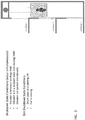
- FIG. 2 depicts sensors installed in an elevator system in an example embodiment.
- the sensors are used to collect operating conditions of the elevator system.
- the operating conditions of the elevator system are then examined to determine if the elevator system is in a shutdown state.
- a first sensor 202 is mounted to the elevator car 103 and functions as an elevator car position sensor.
- the first sensor 202 may read indicia 204 positioned along the hoistway 117.
- the indicia 204 may correspond to unique landing floors.
- the first sensor is an RFID reader that reads RFID tags 204 located along the hoistway 117 (e.g., on a guide rail) to determine location of the elevator car 103. It is understood that other types of sensors and indicia may be used.
- a second sensor 206 functions as motion sensor to determine if the elevator car 103 is moving or stopped.
- the second sensor 206 may be an accelerometer mounted on the top of the elevator car 103 and senses vibration when the elevator car 103 is moving. It is understood that other types of motion sensors may be used.
- a third sensor 208 detects the status of the elevator car door(s), including an open position and a closed position.
- the third sensor 208 may be implemented using two sensors, with one sensor located at each travel limit of the elevator door(s).
- hall-effect sensors are used to detect if the elevator door(s) are opened or closed. It is understood that other types of sensors may be used to detect door position.
- a fourth sensor 210 detects occupancy of the elevator car 103.
- the fourth sensor 210 may detect presence of one or more persons in the elevator car 103 using thermal sensing, audio sensing, image sensing, weight sensing, etc.
- the sensors 202, 206, 208 and 210 are only examples of sensors that may be added to the elevator system in order to sense operating conditions of the elevator system. Other sensors may be installed at various locations to monitor other operating conditions of the elevator system. Additionally, one sensor may be used to perform multiple functions. For example, a single sensor could be used to determine the functions for sensors 202, 206 and 208, or a single sensor could be used for all functions, 202, 206, 208 and 210.
- the sensors 202, 206, 208 and 210 provide respective sensed operating conditions to a sensor interface 220.
- the sensor interface 220 may include a processor 232, a memory 234, and a communication module 236 as shown in FIG. 2 .
- the processor 232 can be any type or combination of computer processors, such as a microprocessor, microcontroller, digital signal processor, application specific integrated circuit, programmable logic device, and/or field programmable gate array.
- the memory 234 is an example of a non-transitory computer readable storage medium tangibly embodied in the sensor interface 220 including executable instructions stored therein, for instance, as firmware.
- the communication module 236 may implement one or more communication protocols to communicate with external devices.
- the sensor interface 220 may communicate with an external device 240 over network 242.
- the external device 240 may be a processor-based device such as a laptop computer, tablet, PDA, a remote server or cloud application, etc.
- the network 242 may be a wireless network, such as 802.11x (WiFi), short-range radio (Bluetooth), or any other known type of wireless communication such as cellular.
- the network 242 may also include wired network elements, such as LAN, WAN, etc.
- the network 242 may also be implemented using a physical interface, such as wired connection using an Ethernet cable, coaxial cable, or other data cable that connects a port on the sensor interface 220 and the external device 240.
- personnel can access the sensor interface 220 over network 242 and retrieve the current state of the elevator system, along with the sensed conditions from sensors 202, 206, 208 and 210.
- the sensor interface 220 collects sensed operating conditions from the sensors 202, 206, 208 and 210 and stores the sensed operating conditions in memory 234, along with a time stamp of when each sensed operating condition occurred.
- the sensor interface 220 may execute a process to detect a shutdown state of the elevator system.
- the sensor interface may be located in a variety of locations such as on the elevator car 103, in a control room, in the cloud, etc.
- FIGs. 3-5 provide examples of detecting a shutdown state of the elevator system.
- FIG. 3 depicts sensed operating conditions indicating a shutdown state in an example embodiment.
- the shutdown state corresponds to an elevator car between landings. Both occupied and unoccupied shutdown states can be reported depending on whether sensor 210 indicates passenger(s) in the elevator car.
- the elevator car is between landings and the elevator car is in a stopped state (not moving) and the elevator car was not parked in that location intentionally. If these three conditions exist for a configurable period of time (e.g., 5 seconds) then the sensor interface 220 concludes that the elevator system is in a shutdown state with an elevator car between landings.
- the sensor interface 220 may store a log of the shutdown state in memory 234.
- the sensor interface 220 can detect when the elevator car is intentionally parked between landings by filtering out conditions of an elevator car stopping between floors that are not shutdowns, such as a mechanic operating the elevator on inspection mode. This may be done by various techniques such as an indication that a mechanic is in a building served by the elevator system (e.g., badge detection), a low speed profile, the connection of a mechanic tool to the sensor interface 220 or the GPS location of a mechanic in the building.
- FIG. 4 depicts sensed operating conditions indicating a shutdown state in an example embodiment.
- the shutdown state corresponds to an elevator car in a shutdown state at a landing before an elevator run commences. Both occupied and unoccupied shutdown states can be reported depending on whether sensor 210 indicates passenger(s) in the elevator car.
- the elevator car stops at a landing, the elevator car door(s) open, the elevator car door(s) close, motion is detected inside the elevator car and the elevator car door(s) open at the same landing. If this sequence of operating conditions is detected a configurable number of times (e.g., 5 times), then the sensor interface 220 concludes that the elevator system is in a shutdown state at a landing.
- the sensor interface 220 may store a log of the shutdown state in memory 234. To exit the shutdown state, the elevator car moves.
- FIG. 5 depicts sensed operating conditions indicating a shutdown state in an example embodiment.
- the shutdown state corresponds to an elevator car in a shutdown state at a landing after an elevator run.
- the elevator car is first moving, the passenger status indicates that the elevator car is occupied, the elevator car stops at landing and the elevator car doors do not open for an extended period of time (e.g., 30 seconds).
- the sensor interface 220 concludes that the elevator system is in a shutdown state at a landing while occupied.
- the sensor interface 220 may store a log of the shutdown state in memory 234.
- To exit the shutdown state either the elevator car doors open or the elevator car moves.
- Embodiments allow maintenance personnel to determine if an elevator system is in a shutdown state without having to access the elevator controller 115. This can be helpful when the maintenance personnel is not affiliated with the manufacturer of the elevator system.
- Embodiments also include sending the sensor information and/or the shutdown state to a remote server or cloud, which may be implemented by external device 240 or another device. Elevator information calculated by the sensor interface 220 may also be sent to the remote server or cloud with the shutdown state. In other embodiments, the sensor information may be sent to a remote server or cloud on a periodic basis to verify elevator operation. Examples of elevator information calculated by the sensor interface includes elevator speed, elevator position (mm or floor number) of the elevator, whether the elevator is at a landing or between landings, door state, passenger status, etc.
- Other information that may be sent with the shutdown state is the condition leading up to the shutdown such as elevator speed, starting landing, distance or time from the starting landing, direction of travel, etc.
- the service provider will use the shutdown state and additional information to dispatch a mechanic to address the shutdown or release a trapped passenger. A dispatch can be cancelled if the shutdown clears.
- the elevator sensor information is sent periodically to the remote server or cloud, the information may also be used to provide additional information for dispatching mechanics for a customer complaint such as elevator position, or to determine that an elevator is functioning correctly.
- the sensors 202, 206, 208 and 210 and sensor interface 220 may be added after the initial installation of the elevator system.
- embodiments can be in the form of processor-implemented processes and devices for practicing those processes, such as a processor in the sensor interface.
- Embodiments can also be in the form of computer program code containing instructions embodied in tangible media, such as network cloud storage, SD cards, flash drives, floppy diskettes, CD ROMs, hard drives, or any other computer-readable storage medium, wherein, when the computer program code is loaded into and executed by a computer, the computer becomes a device for practicing the embodiments.
- Embodiments can also be in the form of computer program code, for example, whether stored in a storage medium, loaded into and/or executed by a computer, or transmitted over some transmission medium, such as over electrical wiring or cabling, through fiber optics, or via electromagnetic radiation, wherein, when the computer program code is loaded into an executed by a computer, the computer becomes an device for practicing the embodiments.
- the computer program code segments configure the microprocessor to create specific logic circuits.
Description
- The embodiments described herein relate generally to an elevator system, and more particularly to an elevator system using sensor-based shutdown detection.
- Elevator systems will occasionally enter a shutdown state due to various events, such as an overspeed condition, machine fault, controller fault, etc. In some situations, maintenance personnel do not have access to the elevator controller in order to determine the exact state of the elevator system. This may occur when the maintenance personnel are not affiliated with the manufacturer of the elevator system. In these situations, the maintenance personnel can find it difficult to determine the current state of the elevator system.
EP3543191 describes a roller guide for an elevator system including a monitoring system comprising arrays of sensors configured to sense roller guide conditions.EP3575258 describes a sensing apparatus for a conveyance system including at least one sensor configured to detect sensor data of the conveyance system, a processor configured to process the sensor data, and a communication module configured to transmit processed sensor data to a remote device.EP3190075 describes an autonomous monitoring unit for an elevator car which can be mounted on the roof of the elevator car and which operates independently of the elevator control system. - According to the invention, an elevator system is provided according to
claim 1. - Some embodiments may include wherein the at least one sensor comprises a plurality of sensors configured to sense a plurality of operating conditions of the elevator system; wherein the sensor interface is configured to detect the shutdown state of the elevator system in response to the plurality of operating conditions.
- Some embodiments may include wherein the plurality of sensors comprise a position sensor, movement sensor, elevator car door sensor and an occupancy sensor.
- Some embodiments may include wherein the sensor interface is configured to detect the shutdown state of the elevator system in response to the elevator car being positioned between landings, the elevator car being stopped and the elevator car not intentionally parked between landings, and wherein the sensor interface is configured to exit the shutdown state in response to the elevator car door being open at a landing or the elevator car moving.
- Some embodiments may include wherein the elevator car intentionally parked between landings is determined by one or more of: an indication that a mechanic is in a building; the elevator car had previously been running at a low speed profile indicative of inspection mode; a detection of a mechanic tool by the sensor interface; or a GPS location of a mechanic in the building.
- Some embodiments may include wherein the sensor interface is configured to detect the shutdown state of the elevator system in response to the elevator car stopped at a landing, the elevator car door opening, the elevator car door closing, occupancy detected in the elevator car and the elevator car door opening, occurring in sequence a number of times, and wherein the sensor interface is configured to exit the shutdown state in response to the elevator car moving.
- Some embodiments may include wherein the sensor interface is configured to detect the shutdown state of the elevator system in response to the elevator car moving, occupancy detected in the elevator car, the elevator car stopping at a landing and the elevator car door not opening for a period of time, occurring in sequence, and wherein the sensor interface is configured to exit the shutdown state in response to the elevator car door opening or the elevator car moving.
- Some embodiments may include wherein the sensor interface is configured to send at least one of the operating condition and the shutdown state to a remote device.
- According to the invention, a method of detecting a state of an elevator system including elevator car configured to travel in a hoistway, the elevator car including an elevator car door and a controller configured to control motion of the elevator car is provided according to claim 9.
- Some embodiments of the method may include wherein sensing the operating condition of the elevator system comprises sensing a plurality of operating conditions of the elevator system; wherein the sensor interface is configured to detect the shutdown state of the elevator system in response to the plurality of operating conditions.
- Some embodiments of the method may include wherein the plurality of operating conditions comprise a position, movement, elevator car door status and occupancy of the elevator car.
- Some embodiments of the method may include detecting the shutdown state of the elevator system in response to the elevator car being positioned between landings, the elevator car being stopped and the elevator car not intentionally parked between landings, and the method may include exiting the shutdown state in response to the elevator car door being open at a landing or the elevator car moving.
- Some embodiments of the method may include wherein the elevator car intentionally parked between landings is determined by one or more of: an indication that a mechanic is in a building; the elevator car had previously been running at a low speed profile indicative of inspection mode; a detection of a mechanic tool by the sensor interface; or a GPS location of a mechanic in the building.
- Some embodiments of the method may include detecting the shutdown state of the elevator system in response to the elevator car stopped at a landing, the elevator car door opening, the elevator car door closing, occupancy detected in the elevator car and the elevator car door opening, occurring in sequence a number of times, and the method may include exiting the shutdown state in response to the elevator car moving.
- Some embodiments of the method may include detecting the shutdown state of the elevator system in response to the elevator car moving, occupancy detected in the elevator car, the elevator car stopping at a landing and the elevator car door not opening for a period of time, occurring in sequence, and the method may include exiting the shutdown state in response to the elevator car door opening or the elevator car moving.
- Some embodiments of the method may include wherein the sensor interface is configured to send at least one of the operating condition and the shutdown state to a remote device.
- Technical effects of embodiments of the present disclosure include the ability to determine a shutdown state of an elevator system, without having access to the elevator controller, using sensors mounted in the elevator system.
- The foregoing features and elements may be combined in various combinations without exclusivity, unless expressly indicated otherwise. These features and elements as well as the operation thereof will become more apparent in light of the following description and the accompanying drawings. It should be understood, however, that the following description and drawings are intended to be illustrative and explanatory in nature and non-limiting.
- The present disclosure is illustrated by way of example and not limited in the accompanying figures in which like reference numerals indicate similar elements.
-
FIG. 1 is a schematic illustration of an elevator system that may employ various embodiments of the present disclosure; -
FIG. 2 depicts sensors installed in an elevator system in an example embodiment; -
FIG. 3 depicts sensed operating conditions indicating a shutdown state in an example embodiment; -
FIG. 4 depicts sensed operating conditions indicating a shutdown state in an example embodiment; -
FIG. 5 depicts sensed operating conditions indicating a shutdown state in an example embodiment. -
FIG. 1 is a perspective view of anelevator system 101 including anelevator car 103, acounterweight 105, atension member 107, aguide rail 109, amachine 111, aposition reference system 113, and acontroller 115. Theelevator car 103 andcounterweight 105 are connected to each other by thetension member 107. Thetension member 107 may include or be configured as, for example, ropes, steel cables, and/or coated-steel belts. Thecounterweight 105 is configured to balance a load of theelevator car 103 and is configured to facilitate movement of theelevator car 103 concurrently and in an opposite direction with respect to thecounterweight 105 within anelevator hoistway 117 and along theguide rail 109. - The
tension member 107 engages themachine 111, which is part of an overhead structure of theelevator system 101. Themachine 111 is configured to control movement between theelevator car 103 and thecounterweight 105. Theposition reference system 113 may be mounted on a fixed part at the top of theelevator hoistway 117, such as on a support or guide rail, and may be configured to provide position signals related to a position of theelevator car 103 within theelevator hoistway 117. In other embodiments, theposition reference system 113 may be directly mounted to a moving component of themachine 111, or may be located in other positions and/or configurations as known in the art. Theposition reference system 113 can be any device or mechanism for monitoring a position of an elevator car and/or counter weight, as known in the art. For example, without limitation, theposition reference system 113 can be an encoder, sensor, or other system and can include velocity sensing, absolute position sensing, etc., as will be appreciated by those of skill in the art. - The
controller 115 is located, as shown, in acontroller room 121 of theelevator hoistway 117 and is configured to control the operation of theelevator system 101, and particularly theelevator car 103. For example, thecontroller 115 may provide drive signals to themachine 111 to control the acceleration, deceleration, leveling, stopping, etc. of theelevator car 103. Thecontroller 115 may also be configured to receive position signals from theposition reference system 113 or any other desired position reference device. When moving up or down within theelevator hoistway 117 alongguide rail 109, theelevator car 103 may stop at one ormore landings 125 as controlled by thecontroller 115. Although shown in acontroller room 121, those of skill in the art will appreciate that thecontroller 115 can be located and/or configured in other locations or positions within theelevator system 101. In one embodiment, the controller may be located remotely or in the cloud. - The
machine 111 may include a motor or similar driving mechanism. In accordance with embodiments of the disclosure, themachine 111 is configured to include an electrically driven motor. The power supply for the motor may be any power source, including a power grid, which, in combination with other components, is supplied to the motor. Themachine 111 may include a traction sheave that imparts force totension member 107 to move theelevator car 103 withinelevator hoistway 117. - Although shown and described with a roping system including
tension member 107, elevator systems that employ other methods and mechanisms of moving an elevator car within an elevator hoistway may employ embodiments of the present disclosure. For example, embodiments may be employed in ropeless elevator systems using a linear motor to impart motion to an elevator car. Embodiments may also be employed in ropeless elevator systems using a hydraulic lift to impart motion to an elevator car.FIG. 1 is merely a non-limiting example presented for illustrative and explanatory purposes. -
FIG. 2 depicts sensors installed in an elevator system in an example embodiment. The sensors are used to collect operating conditions of the elevator system. The operating conditions of the elevator system are then examined to determine if the elevator system is in a shutdown state. Afirst sensor 202 is mounted to theelevator car 103 and functions as an elevator car position sensor. Thefirst sensor 202 may readindicia 204 positioned along thehoistway 117. Theindicia 204 may correspond to unique landing floors. In an example embodiment, the first sensor is an RFID reader that reads RFID tags 204 located along the hoistway 117 (e.g., on a guide rail) to determine location of theelevator car 103. It is understood that other types of sensors and indicia may be used. - A
second sensor 206 functions as motion sensor to determine if theelevator car 103 is moving or stopped. Thesecond sensor 206 may be an accelerometer mounted on the top of theelevator car 103 and senses vibration when theelevator car 103 is moving. It is understood that other types of motion sensors may be used. - A
third sensor 208 detects the status of the elevator car door(s), including an open position and a closed position. Thethird sensor 208 may be implemented using two sensors, with one sensor located at each travel limit of the elevator door(s). In one embodiment, hall-effect sensors are used to detect if the elevator door(s) are opened or closed. It is understood that other types of sensors may be used to detect door position. - A
fourth sensor 210 detects occupancy of theelevator car 103. Thefourth sensor 210 may detect presence of one or more persons in theelevator car 103 using thermal sensing, audio sensing, image sensing, weight sensing, etc. - The
sensors sensors - The
sensors sensor interface 220. Thesensor interface 220 may include aprocessor 232, amemory 234, and acommunication module 236 as shown inFIG. 2 . Theprocessor 232 can be any type or combination of computer processors, such as a microprocessor, microcontroller, digital signal processor, application specific integrated circuit, programmable logic device, and/or field programmable gate array. Thememory 234 is an example of a non-transitory computer readable storage medium tangibly embodied in thesensor interface 220 including executable instructions stored therein, for instance, as firmware. Thecommunication module 236 may implement one or more communication protocols to communicate with external devices. - The
sensor interface 220 may communicate with anexternal device 240 overnetwork 242. Theexternal device 240 may be a processor-based device such as a laptop computer, tablet, PDA, a remote server or cloud application, etc. Thenetwork 242 may be a wireless network, such as 802.11x (WiFi), short-range radio (Bluetooth), or any other known type of wireless communication such as cellular. Thenetwork 242 may also include wired network elements, such as LAN, WAN, etc. Thenetwork 242 may also be implemented using a physical interface, such as wired connection using an Ethernet cable, coaxial cable, or other data cable that connects a port on thesensor interface 220 and theexternal device 240. Using theexternal device 240, personnel can access thesensor interface 220 overnetwork 242 and retrieve the current state of the elevator system, along with the sensed conditions fromsensors - In operation, the
sensor interface 220 collects sensed operating conditions from thesensors memory 234, along with a time stamp of when each sensed operating condition occurred. Thesensor interface 220 may execute a process to detect a shutdown state of the elevator system. The sensor interface may be located in a variety of locations such as on theelevator car 103, in a control room, in the cloud, etc.FIGs. 3-5 provide examples of detecting a shutdown state of the elevator system. -
FIG. 3 depicts sensed operating conditions indicating a shutdown state in an example embodiment. In the example inFIG. 3 , the shutdown state corresponds to an elevator car between landings. Both occupied and unoccupied shutdown states can be reported depending on whethersensor 210 indicates passenger(s) in the elevator car. To enter the shutdown state, the elevator car is between landings and the elevator car is in a stopped state (not moving) and the elevator car was not parked in that location intentionally. If these three conditions exist for a configurable period of time (e.g., 5 seconds) then thesensor interface 220 concludes that the elevator system is in a shutdown state with an elevator car between landings. Thesensor interface 220 may store a log of the shutdown state inmemory 234. To exit the shutdown state, either the car doors are detected as opening at a landing or the elevator car moves. Thesensor interface 220 can detect when the elevator car is intentionally parked between landings by filtering out conditions of an elevator car stopping between floors that are not shutdowns, such as a mechanic operating the elevator on inspection mode. This may be done by various techniques such as an indication that a mechanic is in a building served by the elevator system (e.g., badge detection), a low speed profile, the connection of a mechanic tool to thesensor interface 220 or the GPS location of a mechanic in the building. -
FIG. 4 depicts sensed operating conditions indicating a shutdown state in an example embodiment. In the example inFIG. 4 , the shutdown state corresponds to an elevator car in a shutdown state at a landing before an elevator run commences. Both occupied and unoccupied shutdown states can be reported depending on whethersensor 210 indicates passenger(s) in the elevator car. To enter the shutdown state, the elevator car stops at a landing, the elevator car door(s) open, the elevator car door(s) close, motion is detected inside the elevator car and the elevator car door(s) open at the same landing. If this sequence of operating conditions is detected a configurable number of times (e.g., 5 times), then thesensor interface 220 concludes that the elevator system is in a shutdown state at a landing. Thesensor interface 220 may store a log of the shutdown state inmemory 234. To exit the shutdown state, the elevator car moves. -
FIG. 5 depicts sensed operating conditions indicating a shutdown state in an example embodiment. In the example inFIG. 5 , the shutdown state corresponds to an elevator car in a shutdown state at a landing after an elevator run. To enter the shutdown state, the elevator car is first moving, the passenger status indicates that the elevator car is occupied, the elevator car stops at landing and the elevator car doors do not open for an extended period of time (e.g., 30 seconds). If this sequence of operating conditions is detected, then thesensor interface 220 concludes that the elevator system is in a shutdown state at a landing while occupied. Thesensor interface 220 may store a log of the shutdown state inmemory 234. To exit the shutdown state, either the elevator car doors open or the elevator car moves. - Embodiments allow maintenance personnel to determine if an elevator system is in a shutdown state without having to access the
elevator controller 115. This can be helpful when the maintenance personnel is not affiliated with the manufacturer of the elevator system. Embodiments also include sending the sensor information and/or the shutdown state to a remote server or cloud, which may be implemented byexternal device 240 or another device. Elevator information calculated by thesensor interface 220 may also be sent to the remote server or cloud with the shutdown state. In other embodiments, the sensor information may be sent to a remote server or cloud on a periodic basis to verify elevator operation. Examples of elevator information calculated by the sensor interface includes elevator speed, elevator position (mm or floor number) of the elevator, whether the elevator is at a landing or between landings, door state, passenger status, etc. Other information that may be sent with the shutdown state is the condition leading up to the shutdown such as elevator speed, starting landing, distance or time from the starting landing, direction of travel, etc. The service provider will use the shutdown state and additional information to dispatch a mechanic to address the shutdown or release a trapped passenger. A dispatch can be cancelled if the shutdown clears. If the elevator sensor information is sent periodically to the remote server or cloud, the information may also be used to provide additional information for dispatching mechanics for a customer complaint such as elevator position, or to determine that an elevator is functioning correctly. Thesensors sensor interface 220 may be added after the initial installation of the elevator system. - As described above, embodiments can be in the form of processor-implemented processes and devices for practicing those processes, such as a processor in the sensor interface. Embodiments can also be in the form of computer program code containing instructions embodied in tangible media, such as network cloud storage, SD cards, flash drives, floppy diskettes, CD ROMs, hard drives, or any other computer-readable storage medium, wherein, when the computer program code is loaded into and executed by a computer, the computer becomes a device for practicing the embodiments. Embodiments can also be in the form of computer program code, for example, whether stored in a storage medium, loaded into and/or executed by a computer, or transmitted over some transmission medium, such as over electrical wiring or cabling, through fiber optics, or via electromagnetic radiation, wherein, when the computer program code is loaded into an executed by a computer, the computer becomes an device for practicing the embodiments. When implemented on a general-purpose microprocessor, the computer program code segments configure the microprocessor to create specific logic circuits.
- The terminology used herein is for the purpose of describing particular embodiments only and is not intended to be limiting of the present disclosure. As used herein, the singular forms "a", "an" and "the" are intended to include the plural forms as well, unless the context clearly indicates otherwise. It will be further understood that the terms "comprises" and/or "comprising," when used in this specification, specify the presence of stated features, integers, steps, operations, elements, and/or components, but do not preclude the presence or addition of one or more other features, integers, steps, operations, element components, and/or groups thereof.
- Those of skill in the art will appreciate that various example embodiments are shown and described herein, each having certain features in the particular embodiments, but the present disclosure is not thus limited. Rather, the present disclosure can be modified within the scope of the appended claims. Additionally, while various embodiments of the present disclosure have been described, it is to be understood that aspects of the present disclosure may include only some of the described embodiments. Accordingly, the present disclosure is not to be seen as limited by the foregoing description, but is only limited by the scope of the appended claims.
Claims (13)
- An elevator system (101) comprising:an elevator car (103) configured to travel in a hoistway (117), the elevator car (103) including an elevator car door;a controller (115) configured to control motion of the elevator car (103);at least one sensor (202, 206, 208, 210) configured to sense an operating condition of the elevator system; anda sensor interface (220) configured to detect a shutdown state of the elevator system (101) in response to the operating condition; and characterized in that:
the sensor interface (220) is configured to detect the shutdown state of the elevator system (101) in response to:(i) the elevator car (103) being positioned between landings (125), the elevator car (103) being stopped and the elevator car (103) not intentionally parked between landings; and/or(ii) the elevator car (103) being stopped at a landing, the elevator car door opening, the elevator car door closing, occupancy detected in the elevator car (103) and the elevator car door opening, occurring in sequence a number of times; and/or(iii) the elevator car (103) moving, occupancy being detected in the elevator car (103), the elevator car (103) stopping at a landing and the elevator car door not opening for a period of time, occurring in sequence. - The elevator system (101) of claim 1 wherein:the at least one sensor (202, 206, 208, 210) comprises a plurality of sensors configured to sense a plurality of operating conditions of the elevator system (101);wherein the sensor interface (220) is configured to detect the shutdown state of the elevator system (101) in response to the plurality of operating conditions.
- The elevator system (101) of claim 2 wherein:
the plurality of sensors (202, 206, 208, 210) comprises a position sensor (202), movement sensor (206), elevator car door sensor (208) and an occupancy sensor (210). - The elevator system (101) of any preceding claim, wherein:
when the sensor interface (220) is configured to detect the shutdown state of the elevator system (101) in response to the elevator car (103) being positioned between landings (125), the elevator car (103) being stopped and the elevator car (103) not intentionally parked between landings (125), then the sensor interface (220) is configured to exit the shutdown state in response to the elevator car door being open at a landing or the elevator car (103) moving. - The elevator system (101) of claim 4, wherein:the elevator car (103) being intentionally parked between landings (125) is determined by one or more of:
an indication that a mechanic is in a building;the elevator car (103) had previously been running at a low speed profile indicative of inspection mode;a detection of a mechanic tool by the sensor interface (220); ora GPS location of a mechanic in the building. - The elevator system (101) of any preceding claim, wherein:
when the sensor interface (220) is configured to detect the shutdown state of the elevator system (101) in response to the elevator car (103) being stopped at a landing (125), the elevator car door opening, the elevator car door closing, occupancy detected in the elevator car (103) and the elevator car door opening, occurring in sequence a number of times, then the sensor interface (220) is configured to exit the shutdown state in response to the elevator car (103) moving. - The elevator system (101) of any preceding claim, wherein:
when the sensor interface (220) is configured to detect the shutdown state of the elevator system (101) in response to the elevator car (103) moving, occupancy being detected in the elevator car (103), the elevator car (103) stopping at a landing and the elevator car door not opening for a period of time, occurring in sequence, then the sensor interface (220) is configured to exit the shutdown state in response to the elevator car door opening or the elevator car (103) moving. - The elevator system (101) of any preceding claim, wherein:
the sensor interface (220) is configured to send at least one of the operating condition and the shutdown state to a remote device (240). - A method of detecting a state of an elevator system (101) including elevator car (103) configured to travel in a hoistway, the elevator car (103) including an elevator car door and a controller (115) configured to control motion of the elevator car (103), the method comprising:using at least one sensor (202, 206, 208, 210) to sense an operating condition of the elevator system (101); andat a sensor interface (220), detecting a shutdown state of the elevator system (101) in response to the operating condition; characterized by:
at the sensor interface (220), detecting the shutdown state of the elevator system (101) in response to:(i) the elevator car (103) being positioned between landings (125), the elevator car (103) being stopped and the elevator car (103) not intentionally parked between landings (125); and/or(ii) the elevator car (125) being stopped at a landing, the elevator car door opening, the elevator car door closing, occupancy detected in the elevator car (103) and the elevator car door opening, occurring in sequence a number of times; and/or(iii) the elevator car moving, occupancy being detected in the elevator car (103), the elevator car (103) stopping at a landing (125) and the elevator car door not opening for a period of time, occurring in sequence. - The method of claim 9, wherein:sensing the operating condition of the elevator system (101) comprises sensing a plurality of operating conditions of the elevator system (101); andwherein the sensor interface (220) is configured to detect the shutdown state of the elevator system (101) in response to the plurality of operating conditions.
- The method of claim 10, wherein the plurality of operating conditions comprise a position, movement, elevator car door status and occupancy of the elevator car (103).
- The method of any of claims 9 to 11, wherein:
when the shutdown state of the elevator system (101) is detected in response to the elevator car (103) being positioned between landings (125), the elevator car (103) being stopped and the elevator car (103) not intentionally parked between landings (125); the method further comprising:
exiting the shutdown state in response to the elevator car door being open at a landing or the elevator car (103) moving. - The method of any of claims 9 to 12, wherein:
when the shutdown state of the elevator system (101) is detected in response to the elevator car (103) being stopped at a landing (125), the elevator car door opening, the elevator car door closing, occupancy detected in the elevator car (103) and the elevator car door opening, occurring in sequence a number of times; the method further comprising:
exiting the shutdown state in response to the elevator car (103) moving.
Applications Claiming Priority (1)
| Application Number | Priority Date | Filing Date | Title |
|---|---|---|---|
| US16/135,547 US20200087111A1 (en) | 2018-09-19 | 2018-09-19 | Sensor-based shutdown detection of elevator system |
Publications (3)
| Publication Number | Publication Date |
|---|---|
| EP3628624A2 EP3628624A2 (en) | 2020-04-01 |
| EP3628624A3 EP3628624A3 (en) | 2020-04-15 |
| EP3628624B1 true EP3628624B1 (en) | 2021-10-27 |
Family
ID=67998210
Family Applications (1)
| Application Number | Title | Priority Date | Filing Date |
|---|---|---|---|
| EP19198464.0A Active EP3628624B1 (en) | 2018-09-19 | 2019-09-19 | Sensor-based shutdown detection of elevator system |
Country Status (3)
| Country | Link |
|---|---|
| US (1) | US20200087111A1 (en) |
| EP (1) | EP3628624B1 (en) |
| CN (1) | CN110921449B (en) |
Families Citing this family (5)
| Publication number | Priority date | Publication date | Assignee | Title |
|---|---|---|---|---|
| EP3519336A4 (en) * | 2016-09-29 | 2020-06-10 | KONE Corporation | Electronic information plate of an elevator component |
| US20200017333A1 (en) * | 2018-07-10 | 2020-01-16 | Lift AI, LLC | System for detecting elevator movement |
| US20200071126A1 (en) * | 2018-08-30 | 2020-03-05 | Otis Elevator Company | Determining elevator car location using radio frequency identification |
| US20210371239A1 (en) * | 2020-05-26 | 2021-12-02 | Tadeusz Pawel Witczak | Elevator management system that transmits combined operational and position data to an elevator management center |
| CN116348405A (en) * | 2020-10-16 | 2023-06-27 | 三菱电机楼宇解决方案株式会社 | Stop information providing system for elevator |
Family Cites Families (8)
| Publication number | Priority date | Publication date | Assignee | Title |
|---|---|---|---|---|
| US4622538A (en) * | 1984-07-18 | 1986-11-11 | Otis Elevator Company | Remote monitoring system state machine and method |
| CN101597001B (en) * | 2009-07-03 | 2011-01-05 | 江门市蒙德电气有限公司 | Detection device for detecting level position of elevator |
| CN202107398U (en) * | 2011-05-30 | 2012-01-11 | 杭州市特种设备检测院 | Elevator running state monitoring and malfunction remote alarm system |
| PL3190075T3 (en) * | 2016-12-12 | 2024-02-19 | Lift Technology GmbH | Monitoring unit for monitoring an elevator |
| CN106494960A (en) * | 2016-12-19 | 2017-03-15 | 厦门乃尔电子有限公司 | A kind of lift running safety monitoring and initial failure early warning system and method |
| CN107128765B (en) * | 2017-06-13 | 2020-11-03 | 重庆市特种设备检测研究院 | Fault-tolerant control method and system for elevator in trapped state |
| US11325809B2 (en) * | 2018-03-19 | 2022-05-10 | Otis Elevator Company | Monitoring roller guide health |
| EP3575258A1 (en) * | 2018-05-30 | 2019-12-04 | Otis Elevator Company | Wireless sensor for conveyance system monitoring |
-
2018
- 2018-09-19 US US16/135,547 patent/US20200087111A1/en active Pending
-
2019
- 2019-09-18 CN CN201910880599.5A patent/CN110921449B/en active Active
- 2019-09-19 EP EP19198464.0A patent/EP3628624B1/en active Active
Also Published As
| Publication number | Publication date |
|---|---|
| EP3628624A3 (en) | 2020-04-15 |
| CN110921449B (en) | 2021-04-13 |
| EP3628624A2 (en) | 2020-04-01 |
| CN110921449A (en) | 2020-03-27 |
| US20200087111A1 (en) | 2020-03-19 |
Similar Documents
| Publication | Publication Date | Title |
|---|---|---|
| EP3628624B1 (en) | Sensor-based shutdown detection of elevator system | |
| EP3594160B1 (en) | Elevator sensor system floor mapping | |
| EP2867150B1 (en) | Position and load measurement system for an elevator | |
| US11724910B2 (en) | Monitoring of conveyance system vibratory signatures | |
| US20200102184A1 (en) | Multi-cage lift installation and method for operating a multi-cage lift installation | |
| CN111483898B (en) | Elevator car and door motion monitoring | |
| US20190367325A1 (en) | Wireless sensor for conveyance system monitoring | |
| US10827238B2 (en) | Elevator door sensor integrated with a long range communication gateway | |
| EP3674242B1 (en) | Enhancing elevator sensor operation for improved maintenance | |
| US20200207572A1 (en) | System and method for assigning elevator service based on a detected number of passengers | |
| EP3599199A2 (en) | Capacity shifting between partially-overlapping elevator groups | |
| EP3640188A1 (en) | Continuous quality monitoring of a conveyance system | |
| EP2765109A2 (en) | Control system of the position, speed limit and uncontrolled movements of the cabin or counterweight of an elevator | |
| CN111348498B (en) | Virtual sensor for elevator monitoring | |
| EP3715297A1 (en) | Elevator location determination based on car vibrations or accelerations | |
| EP3808693A1 (en) | Elevator condition based maintenance using an in-car camera | |
| US20200055691A1 (en) | Last-minute hall call request to a departing cab using gesture | |
| EP3878787B1 (en) | Managing elevator call assignments in response to elevator door reversals | |
| EP3650389B1 (en) | Method and device for monitoring an elevator system | |
| KR20190009860A (en) | Elevator control system for reducing arrival errors | |
| US11958722B2 (en) | Virtual sensor for elevator monitoring | |
| WO2012164703A1 (en) | Elevator device | |
| JP2022177618A (en) | elevator diagnostic system |
Legal Events
| Date | Code | Title | Description |
|---|---|---|---|
| PUAI | Public reference made under article 153(3) epc to a published international application that has entered the european phase |
Free format text: ORIGINAL CODE: 0009012 |
|
| STAA | Information on the status of an ep patent application or granted ep patent |
Free format text: STATUS: THE APPLICATION HAS BEEN PUBLISHED |
|
| PUAL | Search report despatched |
Free format text: ORIGINAL CODE: 0009013 |
|
| AK | Designated contracting states |
Kind code of ref document: A2 Designated state(s): AL AT BE BG CH CY CZ DE DK EE ES FI FR GB GR HR HU IE IS IT LI LT LU LV MC MK MT NL NO PL PT RO RS SE SI SK SM TR |
|
| AX | Request for extension of the european patent |
Extension state: BA ME |
|
| AK | Designated contracting states |
Kind code of ref document: A3 Designated state(s): AL AT BE BG CH CY CZ DE DK EE ES FI FR GB GR HR HU IE IS IT LI LT LU LV MC MK MT NL NO PL PT RO RS SE SI SK SM TR |
|
| AX | Request for extension of the european patent |
Extension state: BA ME |
|
| RIC1 | Information provided on ipc code assigned before grant |
Ipc: B66B 5/00 20060101AFI20200312BHEP |
|
| STAA | Information on the status of an ep patent application or granted ep patent |
Free format text: STATUS: REQUEST FOR EXAMINATION WAS MADE |
|
| 17P | Request for examination filed |
Effective date: 20201015 |
|
| RBV | Designated contracting states (corrected) |
Designated state(s): AL AT BE BG CH CY CZ DE DK EE ES FI FR GB GR HR HU IE IS IT LI LT LU LV MC MK MT NL NO PL PT RO RS SE SI SK SM TR |
|
| GRAP | Despatch of communication of intention to grant a patent |
Free format text: ORIGINAL CODE: EPIDOSNIGR1 |
|
| STAA | Information on the status of an ep patent application or granted ep patent |
Free format text: STATUS: GRANT OF PATENT IS INTENDED |
|
| INTG | Intention to grant announced |
Effective date: 20210330 |
|
| GRAS | Grant fee paid |
Free format text: ORIGINAL CODE: EPIDOSNIGR3 |
|
| GRAA | (expected) grant |
Free format text: ORIGINAL CODE: 0009210 |
|
| STAA | Information on the status of an ep patent application or granted ep patent |
Free format text: STATUS: THE PATENT HAS BEEN GRANTED |
|
| AK | Designated contracting states |
Kind code of ref document: B1 Designated state(s): AL AT BE BG CH CY CZ DE DK EE ES FI FR GB GR HR HU IE IS IT LI LT LU LV MC MK MT NL NO PL PT RO RS SE SI SK SM TR |
|
| REG | Reference to a national code |
Ref country code: GB Ref legal event code: FG4D |
|
| REG | Reference to a national code |
Ref country code: CH Ref legal event code: EP |
|
| REG | Reference to a national code |
Ref country code: AT Ref legal event code: REF Ref document number: 1441620 Country of ref document: AT Kind code of ref document: T Effective date: 20211115 |
|
| REG | Reference to a national code |
Ref country code: DE Ref legal event code: R096 Ref document number: 602019008672 Country of ref document: DE |
|
| REG | Reference to a national code |
Ref country code: IE Ref legal event code: FG4D |
|
| REG | Reference to a national code |
Ref country code: LT Ref legal event code: MG9D |
|
| REG | Reference to a national code |
Ref country code: NL Ref legal event code: MP Effective date: 20211027 |
|
| REG | Reference to a national code |
Ref country code: AT Ref legal event code: MK05 Ref document number: 1441620 Country of ref document: AT Kind code of ref document: T Effective date: 20211027 |
|
| PG25 | Lapsed in a contracting state [announced via postgrant information from national office to epo] |
Ref country code: RS Free format text: LAPSE BECAUSE OF FAILURE TO SUBMIT A TRANSLATION OF THE DESCRIPTION OR TO PAY THE FEE WITHIN THE PRESCRIBED TIME-LIMIT Effective date: 20211027 Ref country code: LT Free format text: LAPSE BECAUSE OF FAILURE TO SUBMIT A TRANSLATION OF THE DESCRIPTION OR TO PAY THE FEE WITHIN THE PRESCRIBED TIME-LIMIT Effective date: 20211027 Ref country code: FI Free format text: LAPSE BECAUSE OF FAILURE TO SUBMIT A TRANSLATION OF THE DESCRIPTION OR TO PAY THE FEE WITHIN THE PRESCRIBED TIME-LIMIT Effective date: 20211027 Ref country code: BG Free format text: LAPSE BECAUSE OF FAILURE TO SUBMIT A TRANSLATION OF THE DESCRIPTION OR TO PAY THE FEE WITHIN THE PRESCRIBED TIME-LIMIT Effective date: 20220127 Ref country code: AT Free format text: LAPSE BECAUSE OF FAILURE TO SUBMIT A TRANSLATION OF THE DESCRIPTION OR TO PAY THE FEE WITHIN THE PRESCRIBED TIME-LIMIT Effective date: 20211027 |
|
| PG25 | Lapsed in a contracting state [announced via postgrant information from national office to epo] |
Ref country code: IS Free format text: LAPSE BECAUSE OF FAILURE TO SUBMIT A TRANSLATION OF THE DESCRIPTION OR TO PAY THE FEE WITHIN THE PRESCRIBED TIME-LIMIT Effective date: 20220227 Ref country code: SE Free format text: LAPSE BECAUSE OF FAILURE TO SUBMIT A TRANSLATION OF THE DESCRIPTION OR TO PAY THE FEE WITHIN THE PRESCRIBED TIME-LIMIT Effective date: 20211027 Ref country code: PT Free format text: LAPSE BECAUSE OF FAILURE TO SUBMIT A TRANSLATION OF THE DESCRIPTION OR TO PAY THE FEE WITHIN THE PRESCRIBED TIME-LIMIT Effective date: 20220228 Ref country code: PL Free format text: LAPSE BECAUSE OF FAILURE TO SUBMIT A TRANSLATION OF THE DESCRIPTION OR TO PAY THE FEE WITHIN THE PRESCRIBED TIME-LIMIT Effective date: 20211027 Ref country code: NO Free format text: LAPSE BECAUSE OF FAILURE TO SUBMIT A TRANSLATION OF THE DESCRIPTION OR TO PAY THE FEE WITHIN THE PRESCRIBED TIME-LIMIT Effective date: 20220127 Ref country code: NL Free format text: LAPSE BECAUSE OF FAILURE TO SUBMIT A TRANSLATION OF THE DESCRIPTION OR TO PAY THE FEE WITHIN THE PRESCRIBED TIME-LIMIT Effective date: 20211027 Ref country code: LV Free format text: LAPSE BECAUSE OF FAILURE TO SUBMIT A TRANSLATION OF THE DESCRIPTION OR TO PAY THE FEE WITHIN THE PRESCRIBED TIME-LIMIT Effective date: 20211027 Ref country code: HR Free format text: LAPSE BECAUSE OF FAILURE TO SUBMIT A TRANSLATION OF THE DESCRIPTION OR TO PAY THE FEE WITHIN THE PRESCRIBED TIME-LIMIT Effective date: 20211027 Ref country code: GR Free format text: LAPSE BECAUSE OF FAILURE TO SUBMIT A TRANSLATION OF THE DESCRIPTION OR TO PAY THE FEE WITHIN THE PRESCRIBED TIME-LIMIT Effective date: 20220128 Ref country code: ES Free format text: LAPSE BECAUSE OF FAILURE TO SUBMIT A TRANSLATION OF THE DESCRIPTION OR TO PAY THE FEE WITHIN THE PRESCRIBED TIME-LIMIT Effective date: 20211027 |
|
| REG | Reference to a national code |
Ref country code: DE Ref legal event code: R097 Ref document number: 602019008672 Country of ref document: DE |
|
| PG25 | Lapsed in a contracting state [announced via postgrant information from national office to epo] |
Ref country code: SM Free format text: LAPSE BECAUSE OF FAILURE TO SUBMIT A TRANSLATION OF THE DESCRIPTION OR TO PAY THE FEE WITHIN THE PRESCRIBED TIME-LIMIT Effective date: 20211027 Ref country code: SK Free format text: LAPSE BECAUSE OF FAILURE TO SUBMIT A TRANSLATION OF THE DESCRIPTION OR TO PAY THE FEE WITHIN THE PRESCRIBED TIME-LIMIT Effective date: 20211027 Ref country code: RO Free format text: LAPSE BECAUSE OF FAILURE TO SUBMIT A TRANSLATION OF THE DESCRIPTION OR TO PAY THE FEE WITHIN THE PRESCRIBED TIME-LIMIT Effective date: 20211027 Ref country code: EE Free format text: LAPSE BECAUSE OF FAILURE TO SUBMIT A TRANSLATION OF THE DESCRIPTION OR TO PAY THE FEE WITHIN THE PRESCRIBED TIME-LIMIT Effective date: 20211027 Ref country code: DK Free format text: LAPSE BECAUSE OF FAILURE TO SUBMIT A TRANSLATION OF THE DESCRIPTION OR TO PAY THE FEE WITHIN THE PRESCRIBED TIME-LIMIT Effective date: 20211027 Ref country code: CZ Free format text: LAPSE BECAUSE OF FAILURE TO SUBMIT A TRANSLATION OF THE DESCRIPTION OR TO PAY THE FEE WITHIN THE PRESCRIBED TIME-LIMIT Effective date: 20211027 |
|
| PLBE | No opposition filed within time limit |
Free format text: ORIGINAL CODE: 0009261 |
|
| STAA | Information on the status of an ep patent application or granted ep patent |
Free format text: STATUS: NO OPPOSITION FILED WITHIN TIME LIMIT |
|
| 26N | No opposition filed |
Effective date: 20220728 |
|
| PG25 | Lapsed in a contracting state [announced via postgrant information from national office to epo] |
Ref country code: AL Free format text: LAPSE BECAUSE OF FAILURE TO SUBMIT A TRANSLATION OF THE DESCRIPTION OR TO PAY THE FEE WITHIN THE PRESCRIBED TIME-LIMIT Effective date: 20211027 |
|
| PG25 | Lapsed in a contracting state [announced via postgrant information from national office to epo] |
Ref country code: SI Free format text: LAPSE BECAUSE OF FAILURE TO SUBMIT A TRANSLATION OF THE DESCRIPTION OR TO PAY THE FEE WITHIN THE PRESCRIBED TIME-LIMIT Effective date: 20211027 |
|
| PG25 | Lapsed in a contracting state [announced via postgrant information from national office to epo] |
Ref country code: MC Free format text: LAPSE BECAUSE OF FAILURE TO SUBMIT A TRANSLATION OF THE DESCRIPTION OR TO PAY THE FEE WITHIN THE PRESCRIBED TIME-LIMIT Effective date: 20211027 |
|
| REG | Reference to a national code |
Ref country code: CH Ref legal event code: PL |
|
| REG | Reference to a national code |
Ref country code: BE Ref legal event code: MM Effective date: 20220930 |
|
| PG25 | Lapsed in a contracting state [announced via postgrant information from national office to epo] |
Ref country code: IT Free format text: LAPSE BECAUSE OF FAILURE TO SUBMIT A TRANSLATION OF THE DESCRIPTION OR TO PAY THE FEE WITHIN THE PRESCRIBED TIME-LIMIT Effective date: 20211027 |
|
| PG25 | Lapsed in a contracting state [announced via postgrant information from national office to epo] |
Ref country code: LU Free format text: LAPSE BECAUSE OF NON-PAYMENT OF DUE FEES Effective date: 20220919 |
|
| PG25 | Lapsed in a contracting state [announced via postgrant information from national office to epo] |
Ref country code: LI Free format text: LAPSE BECAUSE OF NON-PAYMENT OF DUE FEES Effective date: 20220930 Ref country code: IE Free format text: LAPSE BECAUSE OF NON-PAYMENT OF DUE FEES Effective date: 20220919 Ref country code: CH Free format text: LAPSE BECAUSE OF NON-PAYMENT OF DUE FEES Effective date: 20220930 |
|
| PG25 | Lapsed in a contracting state [announced via postgrant information from national office to epo] |
Ref country code: BE Free format text: LAPSE BECAUSE OF NON-PAYMENT OF DUE FEES Effective date: 20220930 |
|
| PGFP | Annual fee paid to national office [announced via postgrant information from national office to epo] |
Ref country code: FR Payment date: 20230822 Year of fee payment: 5 Ref country code: DE Payment date: 20230822 Year of fee payment: 5 |
|
| PG25 | Lapsed in a contracting state [announced via postgrant information from national office to epo] |
Ref country code: HU Free format text: LAPSE BECAUSE OF FAILURE TO SUBMIT A TRANSLATION OF THE DESCRIPTION OR TO PAY THE FEE WITHIN THE PRESCRIBED TIME-LIMIT; INVALID AB INITIO Effective date: 20190919 |