EP3638591B1 - Tubenhalter für eine tubenfüllmaschine - Google Patents
Tubenhalter für eine tubenfüllmaschine Download PDFInfo
- Publication number
- EP3638591B1 EP3638591B1 EP18731957.9A EP18731957A EP3638591B1 EP 3638591 B1 EP3638591 B1 EP 3638591B1 EP 18731957 A EP18731957 A EP 18731957A EP 3638591 B1 EP3638591 B1 EP 3638591B1
- Authority
- EP
- European Patent Office
- Prior art keywords
- tube
- tube holder
- receiving means
- magnet
- holder
- Prior art date
- Legal status (The legal status is an assumption and is not a legal conclusion. Google has not performed a legal analysis and makes no representation as to the accuracy of the status listed.)
- Active
Links
Images


Classifications
-
- B—PERFORMING OPERATIONS; TRANSPORTING
- B65—CONVEYING; PACKING; STORING; HANDLING THIN OR FILAMENTARY MATERIAL
- B65B—MACHINES, APPARATUS OR DEVICES FOR, OR METHODS OF, PACKAGING ARTICLES OR MATERIALS; UNPACKING
- B65B43/00—Forming, feeding, opening or setting-up containers or receptacles in association with packaging
- B65B43/42—Feeding or positioning bags, boxes, or cartons in the distended, opened, or set-up state; Feeding preformed rigid containers, e.g. tins, capsules, glass tubes, glasses, to the packaging position; Locating containers or receptacles at the filling position; Supporting containers or receptacles during the filling operation
- B65B43/54—Means for supporting containers or receptacles during the filling operation
-
- B—PERFORMING OPERATIONS; TRANSPORTING
- B65—CONVEYING; PACKING; STORING; HANDLING THIN OR FILAMENTARY MATERIAL
- B65B—MACHINES, APPARATUS OR DEVICES FOR, OR METHODS OF, PACKAGING ARTICLES OR MATERIALS; UNPACKING
- B65B3/00—Packaging plastic material, semiliquids, liquids or mixed solids and liquids, in individual containers or receptacles, e.g. bags, sacks, boxes, cartons, cans, or jars
- B65B3/04—Methods of, or means for, filling the material into the containers or receptacles
- B65B3/16—Methods of, or means for, filling the material into the containers or receptacles for filling collapsible tubes
Definitions
- the invention relates to a tube holder for a tube filling machine, with a cup-shaped housing which has an upwardly opening tube holder into which a tube can be inserted with its one axial end area, a clamping device being arranged in the area of the tube wall of the tube holder, by means of which the Tube a clamping force can be applied.
- a tube filling machine of conventional construction has an endlessly revolving conveyor device which carries a plurality of receptacles, in each of which a tube holder is inserted.
- a tube with its head or cap section can be inserted into each tube holder from above, the tube passing through the individual work stations of the tube filling machine together with the tube holder.
- the filling station and the closing station provision can be made for the tube with its tube holder to be lifted out of the receptacle and inserted into the respective work station, being lowered back into the receptacle after the work step has been completed will.
- a removal station the filled and closed tube is removed from the tube holder and transported away.
- a tube holder of the type mentioned in which at least one clamping element is arranged in the area of the inner wall of the tube holder, which is displaceable essentially perpendicular to the longitudinal center axis of the tube holder and by means of which, under the action of at least one spring element, a clamping force acting radially from the outside on the inserted tube can be applied.
- the clamping element is pivotably mounted.
- Tube holders for a tube filling machine are also in DE 2351762 A1 and DE 19920622 A1 described.
- US 5375898 A describes a container holder for holding a container during transportation, storage, etc. of containers.
- top and bottom refer to the usual alignment of a tube holder with an upward-opening tube holder in which the tube with its head or cap section can be inserted from above so that the tube is to be welded to it The end protrudes from the tube holder at the top.
- its longitudinal center axis extends vertically and the clamping forces clamping the tube in the tube holder are applied essentially perpendicular to the center longitudinal axis and thus essentially horizontally.
- the invention is based on the object of creating a tube holder of the type mentioned, with which a secure holding and good centering of tubes of different formats is ensured.
- this object is achieved by a tube holder with the features of claim 1. It is provided that the clamping device has at least one magnet and preferably several magnets, which can be adjusted by means of at least one electrical coil between a clamping position in which a clamping force is applied to the tube and a release position in which no clamping force is applied to the tube is.
- the invention is based on the basic idea of triggering the adjustment movement by an externally introduced drive force so that it can be adapted to the shape of the tube to be clamped.
- a magnetic field can be generated with this, by means of which the magnet or magnets can be brought either from the clamping position into their release position or from the release position into their clamping position.
- the magnet or magnets return to their original position, which can also be done magnetically and / or as a result of elastic restoring forces and / or by means of a restoring spring.
- the starting position is the clamping position, so that the tube is held securely even when no electromagnetic field is generated.
- the polarity of the magnets can be aligned so that on the one hand the magnets and on the other hand the permanent magnets repel or attract each other when the tube holder with the magnets comes close to the permanent magnets, thereby releasing the tube.
- the polarity of the magnet is aligned in such a way that the tube is clamped when the tube holder with the magnets comes close to the permanent magnets.
- the tube holder usually has a vertically aligned, channel-shaped tube holder.
- at least one chamber is formed in the inner wall of the tube holder, which extends radially outward from the tube holder and in which the magnet or magnets are arranged, the magnet or magnets being connected to a clamping part which, by means of the magnet or can be deformed by means of the magnets into a position protruding into the tube receptacle.
- the clamping part In the release position, the clamping part is withdrawn into the chamber so that it does not exert any clamping force on the tube inserted into the tube holder.
- the clamping part In the starting position, the clamping part preferably protrudes into the tube receptacle. If the magnet or magnets and thus also the clamping part are adjusted by means of the electrical coil and / or by means of the permanent magnet, the clamping part is adjusted relative to the tube holder in such a way that that the tube located there is released.
- the magnet or magnets are embedded in the clamping part.
- the clamping part can, for example, be a body made of a soft, elastic, easily deformable plastic, which can completely fill the chamber in a further development of the invention and can be fixed in it in a form-fitting and / or force-fitting manner, for example by means of adhesive bonding.
- the chamber is designed as a circumferential annular chamber, with several magnets being arranged in the chamber, preferably evenly distributed over the circumference.
- the magnet or magnets are adjustable in the chamber along a guide, wherein the guide can have a bearing, for example a ball bearing. In this way, a defined adjustment movement of the magnet or magnets between the clamping position and the release position is achieved.
- the magnets can be rotatably mounted about the longitudinal axis of the tube holder. This rotation or any other adjustment of the magnet or magnets along the guide can be transmitted to a tensioning element, by means of which a tensioning force can be applied to the tube.
- the tensioning device has a magnetorheological fluid, the viscosity of which can be changed by means of at least one electrical coil and / or by means of a permanent magnet.
- a magnetorheological fluid is a suspension of magnetically polarizable particles that are finely distributed in a carrier fluid. The magnetorheological fluid changes its viscosity when a magnetic field is applied. With increasing field strength of a magnetic field, the viscosity of the magnetorheological fluid increases, ie it becomes more viscous.
- the magnetorheological fluid In the absence of a magnetic field, the magnetorheological fluid has a relatively high viscosity.
- the tube can be inserted into the tube holder, the magnetorheological fluid securely holding the tube.
- a magnetic field acts on the magnetorheological fluid by means of the electrical coil and / or by means of the permanent magnet, whereby the viscosity of the magnetorheological fluid is lower, so that the magnetorheological fluid the Insertion movement or removal movement of the tube is not hindered.
- the magnetorheological fluid is arranged in a fluid chamber which, with a flexible wall, forms at least a section of the inner wall of the tube receptacle.
- the magnetorheological fluid is flowable due to the action of the magnetic field and is partially displaced and deformed while the flexible wall is deformed the tube is surrounded by the magnetorheological fluid in the area of its head and / or its shoulder with the interposition of the flexible wall. After the magnetic field is no longer effective, the magnetorheological fluid becomes so viscous again that it fixes the tube in the specified position.
- the liquid chamber is preferably designed as a completely circumferential annular chamber, so that the tube can be completely fixed on the circumference by the magnetorheological liquid.
- the housing of the tube holder sits in a housing receptacle and can also be removed from this if necessary.
- the electrical coil and / or the permanent magnet can be arranged on the housing receptacle or embedded in it.
- the housing receptacle is preferably designed in an annular manner, so that the tube holder with its housing can be inserted into the interior of the annular design.
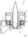
- the tube holder 10 shown has a cup-shaped housing 11 which tapers conically at its lower end and has a radially protruding, circumferential flange 11a in the upper region.
- a cylindrical, vertical through hole is formed which forms a tube receptacle 12 and has an inner wall 12a.
- a circumferential chamber 21 is formed in its inner wall 12a, which chamber is filled with a tensioning part 22 made of a soft, elastic, easily deformable material.
- the clamping part 22 forms a section of the circumferential delimitation of the tube receptacle 12.
- a plurality of magnets 14 distributed over the circumference are embedded in the material of the clamping part 21.
- the magnets 14 are connected to the material of the clamping part 22 in such a way that a movement of the magnets 14 leads to a deformation of the clamping part 22.
- the housing 11 is inserted into a receiving opening 26 of an essentially annular housing receptacle 15, the housing 11 reaching through the receiving opening 26.
- the interior of the housing receptacle is close to the receiving opening 26 25, an electrical coil 16 is arranged, which is connected to an electrical voltage source in a manner not shown.
- an electrical coil 16 is arranged, which is connected to an electrical voltage source in a manner not shown.
- magnets 14 are close to and within electrical coil 16.
- a magnetic field is formed.
- the magnets 14 are displaced radially inward, ie in the direction of the tube holder 12. This results in the clamping part 22 protruding into the tube receptacle 12, as shown in FIG Figure 1 is shown in dashed lines. This allows an in Figure 1 Tube shown are clamped in the tube holder 12.
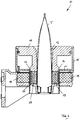
- FIG Figure 2 shows an alternative embodiment of the tube holder 10. This differs from the embodiment according to FIG Figure 1 essentially in that a liquid chamber 24 is now provided in the inner wall 12a of the tube holder 12, which is delimited with respect to the tube holder 12 by a flexible wall 25, for example in the form of a film. A magnetorheological fluid 17 is arranged in the fluid chamber 24.
- the liquid chamber 24 which is preferably designed as a circumferential annular chamber, is located in the area inside the electrical coil 16.
- a magnetic field builds up, as a result of which the viscosity of the magnetorheological fluid 17 in the fluid chamber 24 changes and this becomes increasingly thinner.
- An inserted tube T is fixed on the outside in the tube holder 10 as long as there is no magnetic field due to the coil 16. As soon as a magnetic field is present as a result of the coil 16, the tube T is released, as shown in FIG Fig. 2 is shown.
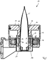
- FIG. 3 The embodiment shown differs from that in Figure 2 The embodiment shown in that, instead of a coil, permanent magnets 18 are now arranged in the housing receptacle 15.
- the magnetorheological fluid 17 comes out of the magnetic field of the permanent magnets 18, whereby its viscosity increases and the tube T is held securely.
- the magnetorheological fluid comes into the magnetic field of the permanent magnets 18, whereby the viscosity of the magnetorheological fluid 17 drops and the tube T is released.
- Figure 4 shows a modification of the embodiment according to Figure 1 .
- the magnets 14 are still embedded in the material of the clamping part 22, but the outer coil arranged in the housing receptacle 15 is replaced by the permanent magnet 18.
- the permanent magnets 18 attract. Since the permanent magnets 18 are held immovable, this leads to an elastic deformation of the clamping part 22 radially outward, ie away from the tube T, whereby the tube is released.
- FIG Figure 5 shows a further modification of the embodiment according to FIG Figure 1 .
- the magnets 14 are now not embedded in the material of a clamping part, but rather adjustable along a guide 19, which includes bearings and in particular ball bearings 23, and in particular rotatable or rotatable about the longitudinal axis of the tube holder 12.
- Clamping elements 20 are provided on the inner wall 12a of the tube holder 12. The adjustment or rotation of the magnets 14 as a result of a magnetic field generated by the coil 16 is mechanically transmitted to the clamping elements 20, whereby a tube T located in the tube holder 12 is clamped or released.
- the magnets 14 When no more current flows through the electrical coil 16 and therefore no magnetic field is present, the magnets 14 return to their starting position, whereby the clamping elements 20 preferably clamp the tube.
Landscapes
- Engineering & Computer Science (AREA)
- Mechanical Engineering (AREA)
- Supports For Pipes And Cables (AREA)
- Sealing Using Fluids, Sealing Without Contact, And Removal Of Oil (AREA)
- Reciprocating Pumps (AREA)
Description
- Die Erfindung betrifft einen Tubenhalter für eine Tubenfüllmaschine, mit einem becherförmigen Gehäuse, das eine nach oben öffnende Tubenaufnahme aufweist, in die eine Tube mit ihrem einen axialen Endbereich einsteckbar ist, wobei im Bereich der Tubenwandung der Tubenaufnahme eine Spannvorrichtung angeordnet ist, mittels der auf die Tube eine Spannkraft aufbringbar ist.
- Eine Tubenfüllmaschine üblichen Aufbaus weist eine endlos umlaufende Fördervorrichtung auf, die eine Vielzahl von Aufnahmen trägt, in die jeweils ein Tubenhalter eingesetzt ist. In jeden Tubenhalter kann von oben eine Tube mit ihrem Kopf- oder Kappenabschnitt eingesetzt werden, wobei die Tube zusammen mit dem Tubenhalter die einzelnen Arbeitsstationen der Tubenfüllmaschine durchläuft. In bestimmten Arbeitsstationen, beispielsweise der Füllstation und der Verschließstation, kann vorgesehen sein, dass die Tube mit ihrem Tubenhalter aus der Aufnahme angehoben und in die jeweilige Arbeitsstation eingeführt wird, wobei sie nach Beendigung des Arbeitsschrittes wieder in die Aufnahme abgesenkt wird. In einer Entnahmestation wird die gefüllte und geschlossene Tube aus dem Tubenhalter entnommen und abtransportiert.
- Aus der
DE 10 2006 055 854 A1 ist ein Tubenhalter der genannten Art bekannt, bei dem im Bereich der Innenwandung der Tubenaufnahme zumindest ein Spannelement angeordnet ist, das im wesentlichen senkrecht zur Längsmittelachse der Tubenaufnahme verlagerbar ist und mittels dessen unter Wirkung zumindest eines Federelementes eine radial von außen auf die eingesetzte Tube wirkende Spannkraft aufgebracht werden kann. Das Spannelement ist dabei schwenkbar gelagert Tubenhalter für eine Tubenfüllmaschine sind auch inDE 2351762 A1 undDE 19920622 A1 beschrieben.US 5375898 A beschreibt einen Behälterhalter zum Halten eines Behälters bei Transport, Lagerung usw. von Behältern. - Die hier verwendeten Bezeichnungen "oben" und "unten" beziehen sich auf die übliche Ausrichtung eines Tubenhalters mit einer nach oben öffnenden Tubenaufnahme, in der die Tube mit ihrem Kopf- oder Kappenabschnitt von oben eingesetzt werden kann, so dass die Tube mit ihrem zu verschweißenden Ende oberseitig aus dem Tubenhalter heraussteht. Bei einer derartigen Ausrichtung des Tubenhalters erstreckt sich dessen Längsmittelachse vertikal und die die Tube in dem Tubenhalter klemmenden Spannkräfte werden im wesentlichen senkrecht zur Mittellängsachse und somit im wesentlichen horizontal aufgebracht.
- Um die Tubenfüllmaschine mit einer hohen Taktzahl betreiben zu können, ist es notwendig, dass die Tuben in dem Tubenhalter exakt positioniert sind. Dabei tritt das Problem auf, dass mit der Tubenfüllmaschine viele Tuben unterschiedlicher Form, insbesondere unterschiedlicher Kappenform und unterschiedlicher Tubenkörperform verarbeitet werden müssen. Darüber hinaus hat sich herausgestellt, dass die Tuben relativ großen Maßtoleranzen unterliegen, wodurch es sehr schwierig ist, eine exakte Positionierung und insbesondere Zentrierung der Tube in dem Tubenhalter zu erreichen.
- Der Erfindung liegt die Aufgabe zugrunde, einen Tubenhalter der genannten Art zu schaffen, mit der eine sichere Halterung und eine gute Zentrierung von Tuben unterschiedlichen Formats gewährleistet ist.
- In einer ersten Ausgestaltung der Erfindung wird diese Aufgabe durch einen Tubenhalter mit den Merkmalen des Anspruchs 1 gelöst. Dabei ist vorgesehen, dass die Spannvorrichtung zumindest einen Magneten und vorzugsweise mehreren Magneten aufweist, die mittels zumindest einer elektrischen Spule zwischen einer Spannstellung, in der auf die Tube eine Spannkraft aufgebracht ist, und einer Freigabestellung verstellbar sind, in der auf die Tube keine Spannkraft aufgebracht ist.
- Die Erfindung geht von der Grundüberlegung aus, die Verstellbewegung durch eine von außen eingebrachte Antriebskraft auszulösen, so dass diese an die Form der zu spannenden Tube angepasst werden kann. Wenn der Antrieb mittels einer elektrischen Spule erfolgt, kann mit dieser ein magnetisches Feld erzeugt werden, durch das der Magnet oder die Magnete entweder aus der Spannstellung in ihre Freigabestellung oder aus der Freigabestellung in ihre Spannstellung gebracht werden können. Nach Abschalten des elektrischen Feldes kehren der Magnet oder die Magnete in ihre Ausgangsstellung zurück, was ebenfalls magnetisch und/oder infolge elastischer Rückstellkräfte und/oder mittels einer Rückstellfeder erfolgen kann. In bevorzugter Ausgestaltung der Erfindung ist vorgesehen, dass die Ausgangsstellung die Spannstellung ist, so dass die Tube auch dann sicher gehalten ist, wenn kein elektromagnetisch Feld erzeugt wird.
- Wenn der Antrieb mittels eines Permanentmagneten erfolgt, kann die Polung der Magnete so ausgerichtet sein, dass sich einerseits die Magnete und andererseits die Permanentmagnete abstoßen oder anziehen, wenn der Tubenhalter mit den Magneten in die Nähe der Permanentmagnete kommt, wodurch die Tube freigegeben wird. Alternativ kann vorgesehen sein, dass die Polung des Magneten so ausgerichtet ist, dass die Tube geklemmt wird, wenn der Tubenhalter mit den Magneten in die Nähe der Permanentmagnete kommt.
- Der Tubenhalter weist die üblicherweise eine vertikal ausgerichtete, kanalförmige Tubenaufnahme auf. In der Innenwandung der Tubenaufnahme ist in bevorzugter Ausgestaltung der Erfindung zumindest eine sich von der Tubenaufnahme radial nach außen erstreckende Kammer ausgebildet, in der der Magnet oder die Magnete angeordnet sind, wobei der Magnet oder die Magnete mit einem Spannteil verbunden sind, das mittels des Magneten oder mittels der Magnete in eine in die Tubenaufnahme hineinragende Stellung verformbar ist. In der Freigabestellung ist das Spannteil in die Kammer zurückgezogen, so dass es auf die in die Tubenaufnahme eingesetzte Tube keine Spannkraft ausübt. In der Ausgangsstellung ragt das Spannteil vorzugsweise in die Tubenaufnahme hinein. Wenn mittels der elektrischen Spule und/oder mittels des Permanentmagneten eine Verstellung des Magneten oder der Magnete und somit auch des Spannteils erfolgt, wird das Spannteil relativ zu der Tubenaufnahme so verstellt, dass sich die dort befindliche Tube freigegeben ist.
- In Weiterbildung der Erfindung kann vorgesehen sein, dass der Magnet oder die Magnete in das Spannteil eingebettet sind. Bei dem Spannteil kann es sich beispielsweise um einen Körper aus einem weich elastischen, leicht verformbaren Kunststoff handeln, der die Kammer in Weiterbildung der Erfindung vollständig ausfüllen kann und in dieser formschlüssig und/oder kraftschlüssig, beispielsweise mittels einer Klebung fixiert sein kann.
- In einer möglichen Ausgestaltung der Erfindung kann vorgesehen sein, dass die Kammer als umlaufende Ringkammer ausgebildet ist, wobei mehrere Magnete über den Umfang vorzugsweise gleich verteilt in der Kammer angeordnet sind.
- In einer weiteren Ausgestaltung der Erfindung kann vorgesehen sein, dass der Magnet oder die Magnete in der Kammer längs einer Führung verstellbar sind, wobei die Führung ein Lager, beispielsweise ein Kugellager aufweisen kann. Auf diese Weise wird eine definierte Verstellbewegung des Magneten oder der Magnete zwischen der Spannstellung und der Freigabestellung erreicht.
- Die Magnete können um die Längsachse der Tubenaufnahme drehbar gelagert sein. Diese Drehung oder jede andere Verstellung des Magnetes oder der Magnete längs der Führung kann auf ein Spannelement übertragen werden, mittels dessen auf die Tube eine Spannkraft aufbringbar ist.
- In einer 2. Ausgestaltung der Erfindung wird die Aufgabe durch einen Tubenhalter mit den Merkmalen des Anspruchs 10 gelöst. Dabei ist vorgesehen, dass die Spannvorrichtung eine magnetorheologische Flüssigkeit aufweist, deren Viskosität mittels zumindest einer elektrischen Spule und/oder mittels eines Permanentmagneten veränderbar ist. Eine magnetorheologische Flüssigkeit ist eine Suspension von magnetisch polarisierbaren Partikeln, die in einer Trägerflüssigkeit fein verteilt sind. Die magnetorheologische Flüssigkeit verändert beim Anlegen eines Magnetfeldes ihre Viskosität. Mit steigender Feldstärke eines Magnetfeldes erhöht sich die Viskosität der magnetorheologischen Flüssigkeit, d.h. sie wird zähflüssiger.
- Ohne Vorhandensein eines Magnetfeldes besitzt die magnetorheologische Flüssigkeit eine relativ hohe Viskosität. Die Tube kann in den Tubenhalter eingesteckt sein, wobei die magnetorheologische Flüssigkeit die Tube sicher hält. Bei dem Einstecken der Tube in die Tubenaufnahme oder beim Entnehmen der Tube aus der Tubenaufnahme wirkt auf die magnetorheologische Flüssigkeit mittels der elektrischen Spule und/oder mittels des Permanentmagneten ein Magnetfeld ein, wodurch die Viskosität der magnetorheologische Flüssigkeit geringer wird, so dass die magnetorheologische Flüssigkeit die Einsteckbewegung oder die Entnahmebewegung der Tube nicht behindert.
- In einer möglichen Ausgestaltung der Erfindung ist vorgesehen, dass die magnetorheologische Flüssigkeit in einer Flüssigkeitskammer angeordnet ist, die mit einer flexiblen Wandung zumindest einen Abschnitt der Innenwandung der Tubenaufnahme bildet. Beim Einführen der Tube in die Tubenaufnahme ist die magnetorheologische Flüssigkeit durch Einwirkung des Magnetfeldes fließfähig und wird unter Verformung der flexiblen Wandung abschnittsweise verdrängt und die Tube ist im Bereich ihres Kopfes und/oder ihrer Schulter unter Zwischenschaltung der flexiblen Wandung von der magnetorheologische Flüssigkeit umgeben. Nachdem das Magnetfeld nicht mehr wirkt, wird die magnetorheologische Flüssigkeit wieder so zähflüssig, dass sie die Tube in der vorgegebenen Position fixiert.
- Vorzugsweise ist die Flüssigkeitskammer als vollständig umlaufende Ringkammer ausgebildet, so dass die Tube umfangsseitig vollständig von der magnetorheologische Flüssigkeit fixiert werden kann.
- In Weiterbildung der Erfindung kann vorgesehen sein, dass das Gehäuse des Tubenhalters in einer Gehäuseaufnahme sitzt und aus dieser bei Bedarf auch entnommen werden kann. Dabei kann die elektrische Spule und/oder der Permanentmagnet an der Gehäuseaufnahme angeordnet oder in diese eingebettet sein.
- Vorzugsweise ist die Gehäuseaufnahme ringförmig ausgebildet, so dass der Tubenhalter mit seinem Gehäuse in den Innenraum der ringförmigen Gestaltung eingeführt werden kann.
- Weitere Einzelheiten und Merkmale der Erfindung sind aus der folgenden Beschreibung von Ausführungsbeispielen unter Bezugnahme auf die Zeichnung ersichtlich. Es zeigen:
- Fig. 1
- Eine schematische Schnittdarstellung eines Tubenhalters gemäß einem 1. Ausführungsbeispiel,
- Fig. 2
- eine schematische Schnittdarstellung eines Tubenhalters gemäß einem 2. Ausführungsbeispiel,
- Fig. 3
- eine schematische Schnittdarstellung eines Tubenhalters gemäß einem 3. Ausführungsbeispiel,
- Fig. 4
- eine schematische Schnittdarstellung eines Tubenhalters gemäß einem 4. Ausführungsbeispiel und
- Fig. 5
- eine schematische Schnittdarstellung eines Tubenhalters gemäß einem 5. Ausführungsbeispiel.
- Ein in
Figur 1 dargestellter Tubenhalter 10 besitzt ein becherförmiges Gehäuse 11, das an seinem unteren Ende sich konisch verjüngt und im oberen Bereich einen radial hervorstehenden, umlaufenden Flansch 11a aufweist. In dem Gehäuse 11 ist eine zylinderförmige, vertikale Durchgangsbohrung ausgebildet, die eine Tubenaufnahme 12 bildet und eine Innenwandung 12a besitzt. Im unteren Bereich der axialen Länge der Tubenaufnahme 12 ist in deren Innenwandung 12a eine umlaufende Kammer 21 ausgebildet, die mit einem aus einem weich-elastischen, leicht verformbaren Material bestehenden Spannteil 22 gefüllt ist. WieFigur 1 zeigt, bildet das Spannteil 22 einen Abschnitt der umfangsseitigen Begrenzung der Tubenaufnahme 12. - In das Material des Spannteils 21 sind mehrere über den Umfang verteilte Magnete 14 eingebettet. Die Magnete 14 sind so mit dem Material des Spannteils 22 verbunden, das eine Bewegung der Magnete 14 zu einer Verformung des Spannteils 22 führt.
- Das Gehäuse 11 ist in eine Aufnahmeöffnung 26 einer im wesentlichen ringförmigen Gehäuseaufnahme 15 eingesetzt, wobei das Gehäuse 11 die Aufnahmeöffnung 26 durchgreift. Nahe der Aufnahmeöffnung 26 ist im Inneren der Gehäuseaufnahme 25 eine elektrische Spule 16 angeordnet, die in nicht dargestellter Weise mit einer elektrischen Spannungsquelle verbunden ist. Wenn das Gehäuse 11 in die Gehäuseaufnahme 15 eingesetzt ist, wie es in
Figur 1 dargestellt ist, liegen die Magnete 14 nahe der elektrischen Spule 16 und innerhalb von dieser. Wenn die elektrische Spule 16 von Strom durchflossen wird, bildet sich ein Magnetfeld. Solange kein Magnetfeld vorhanden ist, sind die Magnete 14 radial nach innen, d.h. in Richtung der Tubenaufnahme 12 verschoben. Dies führt dazu, dass das Spannteil 22, in die Tubenaufnahme 12 hervorsteht, wie es inFigur 1 gestrichelt dargestellt ist. Dadurch kann eine inFigur 1 dargestellte Tube in der Tubenaufnahme 12 festgespannt werden. - Sobald die elektrische Spule 16 von Strom durchflossen ist, ist ein Magnetfeld vorhanden und die Magnete 14 nehmen zusammen mit dem Spannteil 22 ihre in
Figur 1 durchgezogen dargestellte Freigabestellung ein. -
Figur 2 zeigt eine alternative Ausgestaltung des Tubenhalters 10. Diese unterscheidet sich von der Ausgestaltung gemäßFigur 1 im wesentlichen dadurch, dass in der Innenwandung 12a der Tubenaufnahme 12 nunmehr eine Flüssigkeitskammer 24 vorgesehen ist, die gegenüber der Tubenaufnahme 12 durch eine flexible Wandung 25 beispielsweise in Form einer Folie begrenzt ist. In der Flüssigkeitskammer 24 ist eine magnetorheologische Flüssigkeit 17 angeordnet. - Wenn der Tubenhalter 10 in die Aufnahmeöffnung 26 der Gehäuseaufnahme 15 eingesetzt ist, wie es in
Figur 2 dargestellt ist, befindet sich die Flüssigkeitskammer 24, die vorzugsweise als umlaufende Ringkammer ausgebildet ist, im Bereich im Inneren der elektrischen Spule 16. Wenn durch diese ein elektrischer Strom fließt, baut sich ein Magnetfeld auf, wodurch sich die Viskosität der magnetorheologische Flüssigkeit 17 in der Flüssigkeitskammer 24 ändert und diese zunehmend dünnflüssiger wird. Eine eingesetzte Tube T ist in dem Tubenhalter 10 außenseitig fixiert, solange kein Magnetfeld infolge der Spule 16 vorhanden ist. Sobald ein Magnetfeld infolge der Spule 16 vorhanden ist, ist die Tube T freigegeben, wie es inFig. 2 dargestellt ist. - Sobald die elektrische Spule 16 nicht mehr von Strom durchflossen ist, ist kein Magnetfeld mehr vorhanden und die magnetorheologische Flüssigkeit 17 spannt die Tube T wieder fest.
- Die in
Figur 3 dargestellte Ausführungsform unterscheidet sich von der inFigur 2 dargestellten Ausführungsform dadurch, dass in der Gehäuseaufnahme 15 statt einer Spule nunmehr Permanentmagneten 18 angeordnet sind. Wenn das Gehäuse 11 aus der Gehäuseaufnahme 15 herausgehoben wird, kommt die magnetorheologische Flüssigkeit 17 aus dem Magnetfeld der Permanentmagneten 18 heraus, wodurch ihre Viskosität steigt und die Tube T sicher gehalten ist. Wenn das Gehäuse 11 anschließend mit einer eingesetzten Tube T in die Gehäuseaufnahme 15 eingesetzt wird, kommt die magnetorheologische Flüssigkeit in das Magnetfeld der Permanentmagneten 18, wodurch die Viskosität der magnetorheologische Flüssigkeit 17 sinkt und die Tube T freigegeben ist. -
Figur 4 zeigt eine Abwandlung der Ausgestaltung gemäßFigur 1 . Dabei sind die Magnete 14 weiterhin in das Material des Spannteils 22 eingebettet, jedoch ist die äußere, in der Gehäuseaufnahme 15 angeordnete Spule durch den Permanentmagneten 18 ersetzt. Wenn der Tubenhalter 10 in die Tubenaufnahme 12 eingesteckt wird, ziehen sich einerseits die Magnete 14 und andererseits die Permanentmagnete 18 an. Da die Permanentmagnete 18 unverschieblich gehalten sind, führt dies zu einer elastischen Verformung des Spannteils 22 radial nach außen, d.h. weg von der Tube T, wodurch die Tube freigegeben wird. -
Figur 5 zeigt eine weitere Abwandlung der Ausgestaltung gemäßFigur 1 . Die Magnete 14 sind nunmehr nicht in das Material eines Spannteils eingebettet, sondern längs einer Führung 19, die Lager und insbesondere Kugellager 23 umfasst, verstellbar und insbesondere um die Längsachse der Tubenaufnahme 12 drehbar oder rotierbar. An der Innenwandung 12a der Tubenaufnahme 12 sind Spannelemente 20 vorgesehen. Die Verstellung oder Drehung der Magnete 14 infolge eines Magnetfeldes, das durch die Spule 16 erzeugt wird, wird mechanisch auf die Spannelemente 20 übertragen, wodurch eine in der Tubenaufnahme 12 befindliche Tube T geklemmt oder freigegeben wird. - Wenn durch die elektrische Spule 16 kein Strom mehr fließt und somit kein Magnetfeld vorhanden ist, kehren die Magnete 14 in ihrer Ausgangsstellung zurück, wodurch die Spannelemente 20 die Tube vorzugsweise klemmen.
Claims (15)
- Tubenhalter für eine Tubenfüllmaschine, mit einem becherförmigen Gehäuse (11), das eine nach oben öffnende Tubenaufnahme (12) aufweist, in die eine Tube (T) mit ihrem einen axialen Endbereich einsteckbar ist, wobei im Bereich der Innenwandung (12a) der Tubenaufnahme (12) eine Spannvorrichtung (13) angeordnet ist, mittels der auf die Tube (T) eine Spannkraft aufbringbar ist, dadurch gekennzeichnet, dass die Spannvorrichtung (13) zumindest einen Magneten (14) aufweist, der mittels zumindest einer elektrischen Spule (16) zwischen einer Spannstellung, in der auf die Tube (T) eine Spannkraft aufgebracht ist, und einer Freigabestellung verstellbar ist, in der auf die Tube (T) keine Spannkraft aufgebracht ist.
- Tubenhalter nach Anspruch 1, dadurch gekennzeichnet, dass in der Innenwandung (12a) der Tubenaufnahme (12) zumindest eine Kammer (21) ausgebildet ist, in der der Magnet (14) angeordnet ist, wobei der Magnet (14) mit einem Spannteil (22) verbunden ist, das mittels des Magneten (14) in eine in die Tubenaufnahme (12) hineinragende Stellung verformbar ist.
- Tubenhalter nach Anspruch 2, dadurch gekennzeichnet, dass der Magnet (14) in das Spannteil (12) eingebettet ist.
- Tubenhalter nach Anspruch 2 oder 3, dadurch gekennzeichnet, dass das Spannteil (22) die Kammer (21) vollständig ausfüllt.
- Tubenhalter nach einem der Ansprüche 2 bis 4, dadurch gekennzeichnet, dass die Kammer (21) als umlaufende Ringkammer ausgebildet ist.
- Tubenhalter nach einem der Ansprüche 2 bis 5, dadurch gekennzeichnet, dass mehrere Magnete (14) über den Umfang verteilt in der Kammer (21) angeordnet sind.
- Tubenhalter nach einem der Ansprüche 1 bis 6, dadurch gekennzeichnet, dass der Magnet (14) in der Kammer (21) längs einer Führung (19) verstellbar ist.
- Tubenhalter nach Anspruch 7, dadurch gekennzeichnet, dass die Führung (19) ein Lager und insbesondere ein Kugellager aufweist.
- Tubenhalter nach Anspruch 7 oder 8, dadurch gekennzeichnet, dass die Verstellung des Magnets (14) längs der Führung (19) auf ein Spannelement (20) übertragbar ist, mittels dessen auf die Tube (T) eine Spannkraft aufbringbar ist.
- Tubenhalter für eine Tubenfüllmaschine, mit einem becherförmigen Gehäuse (11), das eine nach oben öffnende Tubenaufnahme (12) aufweist, in die eine Tube (T) mit ihrem einen axialen Endbereich einsteckbar ist, wobei im Bereich der Innenwandung (12a) der Tubenaufnahme (12) eine Spannvorrichtung (13) angeordnet ist, mittels der auf die Tube (T) eine Spannkraft aufbringbar ist, dadurch gekennzeichnet, dass die Spannvorrichtung (13) eine magnetorheologische Flüssigkeit (17) aufweist, deren Viskosität mittels zumindest einer elektrischen Spule (16) und/oder zumindest eines Permanentmagneten (18) veränderbar ist.
- Tubenhalter nach Anspruch 10, dadurch gekennzeichnet, dass die magnetorheologische Flüssigkeit (17) in einer Flüssigkeitskammer (24) angeordnet ist, die mit einer flexiblen Wandung (25) zumindest einen Abschnitt der Innenwandung (12a) der Tubenaufnahme (12) bildet.
- Tubenhalter nach Anspruch 11, dadurch gekennzeichnet, dass die Flüssigkeitskammer (24) als umlaufende Ringkammer ausgebildet ist.
- Tubenhalter nach einem der Ansprüche 1 bis 9, dadurch gekennzeichnet, dass das Gehäuse (11) in einer Gehäuseaufnahme (15) sitzt und dass die elektrische Spule (16) in oder an der Gehäuseaufnahme (15) angeordnet ist.
- Tubenhalter nach einem der Ansprüche 10 bis 12, dadurch gekennzeichnet, dass das Gehäuse (11) in einer Gehäuseaufnahme (15) sitzt und dass die elektrisehe Spule (16) und/oder der Permanentmagnet (18) in oder an der Gehäuseaufnahme (15) angeordnet sind.
- Tubenhalter nach Anspruch 13 oder 14, dadurch gekennzeichnet, dass die Gehäuseaufnahme (15) ringförmig ausgebildet ist.
Applications Claiming Priority (2)
| Application Number | Priority Date | Filing Date | Title |
|---|---|---|---|
| DE102017005610.2A DE102017005610A1 (de) | 2017-06-14 | 2017-06-14 | Tubenhalter für eine Tubenfüllmaschine |
| PCT/EP2018/000283 WO2018228719A1 (de) | 2017-06-14 | 2018-06-01 | Tubenhalter für eine tubenfüllmaschine |
Publications (2)
| Publication Number | Publication Date |
|---|---|
| EP3638591A1 EP3638591A1 (de) | 2020-04-22 |
| EP3638591B1 true EP3638591B1 (de) | 2021-07-21 |
Family
ID=62636144
Family Applications (1)
| Application Number | Title | Priority Date | Filing Date |
|---|---|---|---|
| EP18731957.9A Active EP3638591B1 (de) | 2017-06-14 | 2018-06-01 | Tubenhalter für eine tubenfüllmaschine |
Country Status (4)
| Country | Link |
|---|---|
| US (1) | US11358743B2 (de) |
| EP (1) | EP3638591B1 (de) |
| DE (1) | DE102017005610A1 (de) |
| WO (1) | WO2018228719A1 (de) |
Families Citing this family (3)
| Publication number | Priority date | Publication date | Assignee | Title |
|---|---|---|---|---|
| DE102019211269A1 (de) | 2019-07-30 | 2021-02-04 | Robert Bosch Gmbh | Haltevorrichtung mit magnetorheologischer Flüssigkeit, Roboter, Maschine, Flaschenverschlussvorrichtung und Halteverfahren |
| CN112201986B (zh) * | 2020-09-30 | 2021-11-30 | 上海旺链信息科技有限公司 | 一种区块链服务器带有防脱落作用的数据线安装架 |
| CN112224543B (zh) * | 2020-10-30 | 2022-08-09 | 吴鸾巧 | 一种软冻拌酱肉丁包装速冻设备 |
Family Cites Families (11)
| Publication number | Priority date | Publication date | Assignee | Title |
|---|---|---|---|---|
| US3819194A (en) | 1972-10-16 | 1974-06-25 | Domain Ind Inc | Tube holder |
| SE458677B (sv) * | 1986-10-06 | 1989-04-24 | Norden Packaging Mach | Anordning vid tubfyllningsmaskin |
| SU1404336A1 (ru) * | 1986-12-02 | 1988-06-23 | Украинский Научно-Исследовательский Институт Станков И Инструментов | Схват промышленного робота |
| US4958667A (en) * | 1989-07-17 | 1990-09-25 | R. A. Jones & Co., Inc. | Tube holder for tube filling machines |
| JP2576417Y2 (ja) * | 1992-10-27 | 1998-07-09 | 花王株式会社 | 物品保持具 |
| DE19920622A1 (de) | 1999-05-05 | 2000-11-09 | Iwk Verpackungstechnik Gmbh | Tubenhalter in einer Tubenfüllmaschine |
| DE102005041929A1 (de) * | 2005-09-03 | 2007-03-08 | Krones Ag | Greifer für Behälter |
| DE102006055854A1 (de) | 2006-11-27 | 2008-05-29 | Iwk Verpackungstechnik Gmbh | Tubenhalter für eine Tubenfüllmaschine |
| DE102007042433A1 (de) * | 2007-09-06 | 2009-03-12 | Iwk Verpackungstechnik Gmbh | Verfahren und Vorrichtung zum Befüllen von Tuben in einer Tubenfüllmaschine |
| DE102008062315A1 (de) * | 2008-12-11 | 2010-06-17 | Khs Corpoplast Gmbh & Co. Kg | Verfahren und Vorrichtung zur Übergabe von Werkstücken |
| DE102018005511A1 (de) * | 2018-07-12 | 2020-01-16 | Iwk Verpackungstechnik Gmbh | Tubenhalter für eine Tubenfüllmaschine |
-
2017
- 2017-06-14 DE DE102017005610.2A patent/DE102017005610A1/de not_active Withdrawn
-
2018
- 2018-06-01 US US16/500,647 patent/US11358743B2/en active Active
- 2018-06-01 EP EP18731957.9A patent/EP3638591B1/de active Active
- 2018-06-01 WO PCT/EP2018/000283 patent/WO2018228719A1/de not_active Ceased
Also Published As
| Publication number | Publication date |
|---|---|
| US11358743B2 (en) | 2022-06-14 |
| EP3638591A1 (de) | 2020-04-22 |
| US20200108961A1 (en) | 2020-04-09 |
| WO2018228719A1 (de) | 2018-12-20 |
| DE102017005610A1 (de) | 2018-12-20 |
Similar Documents
| Publication | Publication Date | Title |
|---|---|---|
| EP2870379B1 (de) | Verfahren zur herstellung einer baugruppe und baugruppe | |
| EP3638591A1 (de) | Tubenhalter für eine tubenfüllmaschine | |
| WO2019048154A1 (de) | Etikettieraggregat und aufnahmedorn für ein etikettieraggregat | |
| DE69116708T2 (de) | Selbstabdichtendes Zentrifugenrohr | |
| EP0275441A1 (de) | Spannvorrichtung | |
| DE3739714C1 (en) | Device for closing and sealing the free end of a cable conduit | |
| EP3036438A2 (de) | System zur förderung flüssiger medien aus einem bohrloch sowie verfahren zur installation einer als exzenterschneckenpumpe ausgebildeten pumpeinheit in einem bohrloch | |
| DE102016220425A1 (de) | Pipettiervorrichtung mit einfach austauschbarem Magnetkolben | |
| EP3594134A1 (de) | Tubenhalter für eine tubenfüllmaschine | |
| EP0248061A1 (de) | Verankerungsbolzen für betonteile. | |
| DE69402019T2 (de) | Zentrifugenröhre mit einschnappenden stopfen | |
| DE102023108049A1 (de) | Vorrichtung zum Befestigen eines Objektivs | |
| EP2657179B1 (de) | Vorrichtung zum Verschließen von Kunststoffflaschen | |
| DE1614198B2 (de) | Spritzgießform zum Einbetten eines Elektromagneten in Kunststoff durch Spritzgießen | |
| DE102014219535A1 (de) | Kinematische Kette für ein elektrisches Schaltgerät sowie Verfahren zur Einstellung eines Relativabstandes von Schaltkontaktstücken | |
| WO2012049010A1 (de) | Werkzeug zum einlegen eines einsatzteils mit einer öffnung in eine spritzgussform | |
| DE3420673A1 (de) | Herstellverfahren fuer einen ausgleichsbehaelter | |
| DE3812855A1 (de) | Gleitlager | |
| AT308386B (de) | Spritzgußform | |
| DE102008039912A1 (de) | Vorrichtung und Verfahren zum Herstellen eines Rotors | |
| DE102010022834A1 (de) | Federdorn und Gießmodell mit Federdorn | |
| DE102017117068A1 (de) | Verbindungshülse und Verbindungsverfahren für gekühlte Stromkabel | |
| DE19821070C1 (de) | Spritzgießmaschine zum Umspritzen eines stabförmigen Werkstücks, insbesondere zum Umspritzen einer Ankerwelle eines Elektromotors mit Kunststoff | |
| WO2000048919A1 (de) | Kunststoff-schraubverschluss für behälter und verfahren zur herstellung eines kunststoff-schraubverschlusses | |
| EP2250009A1 (de) | Rohrförmiger behälter |
Legal Events
| Date | Code | Title | Description |
|---|---|---|---|
| STAA | Information on the status of an ep patent application or granted ep patent |
Free format text: STATUS: UNKNOWN |
|
| STAA | Information on the status of an ep patent application or granted ep patent |
Free format text: STATUS: THE INTERNATIONAL PUBLICATION HAS BEEN MADE |
|
| PUAI | Public reference made under article 153(3) epc to a published international application that has entered the european phase |
Free format text: ORIGINAL CODE: 0009012 |
|
| STAA | Information on the status of an ep patent application or granted ep patent |
Free format text: STATUS: REQUEST FOR EXAMINATION WAS MADE |
|
| 17P | Request for examination filed |
Effective date: 20190829 |
|
| AK | Designated contracting states |
Kind code of ref document: A1 Designated state(s): AL AT BE BG CH CY CZ DE DK EE ES FI FR GB GR HR HU IE IS IT LI LT LU LV MC MK MT NL NO PL PT RO RS SE SI SK SM TR |
|
| AX | Request for extension of the european patent |
Extension state: BA ME |
|
| DAV | Request for validation of the european patent (deleted) | ||
| DAX | Request for extension of the european patent (deleted) | ||
| GRAP | Despatch of communication of intention to grant a patent |
Free format text: ORIGINAL CODE: EPIDOSNIGR1 |
|
| STAA | Information on the status of an ep patent application or granted ep patent |
Free format text: STATUS: GRANT OF PATENT IS INTENDED |
|
| GRAJ | Information related to disapproval of communication of intention to grant by the applicant or resumption of examination proceedings by the epo deleted |
Free format text: ORIGINAL CODE: EPIDOSDIGR1 |
|
| STAA | Information on the status of an ep patent application or granted ep patent |
Free format text: STATUS: REQUEST FOR EXAMINATION WAS MADE |
|
| INTG | Intention to grant announced |
Effective date: 20201223 |
|
| GRAP | Despatch of communication of intention to grant a patent |
Free format text: ORIGINAL CODE: EPIDOSNIGR1 |
|
| STAA | Information on the status of an ep patent application or granted ep patent |
Free format text: STATUS: GRANT OF PATENT IS INTENDED |
|
| INTC | Intention to grant announced (deleted) | ||
| INTG | Intention to grant announced |
Effective date: 20210215 |
|
| GRAS | Grant fee paid |
Free format text: ORIGINAL CODE: EPIDOSNIGR3 |
|
| GRAA | (expected) grant |
Free format text: ORIGINAL CODE: 0009210 |
|
| STAA | Information on the status of an ep patent application or granted ep patent |
Free format text: STATUS: THE PATENT HAS BEEN GRANTED |
|
| AK | Designated contracting states |
Kind code of ref document: B1 Designated state(s): AL AT BE BG CH CY CZ DE DK EE ES FI FR GB GR HR HU IE IS IT LI LT LU LV MC MK MT NL NO PL PT RO RS SE SI SK SM TR |
|
| REG | Reference to a national code |
Ref country code: GB Ref legal event code: FG4D Free format text: NOT ENGLISH |
|
| REG | Reference to a national code |
Ref country code: CH Ref legal event code: EP |
|
| REG | Reference to a national code |
Ref country code: DE Ref legal event code: R096 Ref document number: 502018006233 Country of ref document: DE |
|
| REG | Reference to a national code |
Ref country code: AT Ref legal event code: REF Ref document number: 1412409 Country of ref document: AT Kind code of ref document: T Effective date: 20210815 |
|
| REG | Reference to a national code |
Ref country code: IE Ref legal event code: FG4D Free format text: LANGUAGE OF EP DOCUMENT: GERMAN |
|
| REG | Reference to a national code |
Ref country code: SE Ref legal event code: TRGR |
|
| REG | Reference to a national code |
Ref country code: LT Ref legal event code: MG9D |
|
| REG | Reference to a national code |
Ref country code: NL Ref legal event code: MP Effective date: 20210721 |
|
| PG25 | Lapsed in a contracting state [announced via postgrant information from national office to epo] |
Ref country code: HR Free format text: LAPSE BECAUSE OF FAILURE TO SUBMIT A TRANSLATION OF THE DESCRIPTION OR TO PAY THE FEE WITHIN THE PRESCRIBED TIME-LIMIT Effective date: 20210721 Ref country code: ES Free format text: LAPSE BECAUSE OF FAILURE TO SUBMIT A TRANSLATION OF THE DESCRIPTION OR TO PAY THE FEE WITHIN THE PRESCRIBED TIME-LIMIT Effective date: 20210721 Ref country code: FI Free format text: LAPSE BECAUSE OF FAILURE TO SUBMIT A TRANSLATION OF THE DESCRIPTION OR TO PAY THE FEE WITHIN THE PRESCRIBED TIME-LIMIT Effective date: 20210721 Ref country code: RS Free format text: LAPSE BECAUSE OF FAILURE TO SUBMIT A TRANSLATION OF THE DESCRIPTION OR TO PAY THE FEE WITHIN THE PRESCRIBED TIME-LIMIT Effective date: 20210721 Ref country code: NO Free format text: LAPSE BECAUSE OF FAILURE TO SUBMIT A TRANSLATION OF THE DESCRIPTION OR TO PAY THE FEE WITHIN THE PRESCRIBED TIME-LIMIT Effective date: 20211021 Ref country code: NL Free format text: LAPSE BECAUSE OF FAILURE TO SUBMIT A TRANSLATION OF THE DESCRIPTION OR TO PAY THE FEE WITHIN THE PRESCRIBED TIME-LIMIT Effective date: 20210721 Ref country code: PT Free format text: LAPSE BECAUSE OF FAILURE TO SUBMIT A TRANSLATION OF THE DESCRIPTION OR TO PAY THE FEE WITHIN THE PRESCRIBED TIME-LIMIT Effective date: 20211122 Ref country code: LT Free format text: LAPSE BECAUSE OF FAILURE TO SUBMIT A TRANSLATION OF THE DESCRIPTION OR TO PAY THE FEE WITHIN THE PRESCRIBED TIME-LIMIT Effective date: 20210721 Ref country code: BG Free format text: LAPSE BECAUSE OF FAILURE TO SUBMIT A TRANSLATION OF THE DESCRIPTION OR TO PAY THE FEE WITHIN THE PRESCRIBED TIME-LIMIT Effective date: 20211021 |
|
| PG25 | Lapsed in a contracting state [announced via postgrant information from national office to epo] |
Ref country code: PL Free format text: LAPSE BECAUSE OF FAILURE TO SUBMIT A TRANSLATION OF THE DESCRIPTION OR TO PAY THE FEE WITHIN THE PRESCRIBED TIME-LIMIT Effective date: 20210721 Ref country code: LV Free format text: LAPSE BECAUSE OF FAILURE TO SUBMIT A TRANSLATION OF THE DESCRIPTION OR TO PAY THE FEE WITHIN THE PRESCRIBED TIME-LIMIT Effective date: 20210721 Ref country code: GR Free format text: LAPSE BECAUSE OF FAILURE TO SUBMIT A TRANSLATION OF THE DESCRIPTION OR TO PAY THE FEE WITHIN THE PRESCRIBED TIME-LIMIT Effective date: 20211022 |
|
| REG | Reference to a national code |
Ref country code: DE Ref legal event code: R097 Ref document number: 502018006233 Country of ref document: DE |
|
| PG25 | Lapsed in a contracting state [announced via postgrant information from national office to epo] |
Ref country code: DK Free format text: LAPSE BECAUSE OF FAILURE TO SUBMIT A TRANSLATION OF THE DESCRIPTION OR TO PAY THE FEE WITHIN THE PRESCRIBED TIME-LIMIT Effective date: 20210721 |
|
| PLBE | No opposition filed within time limit |
Free format text: ORIGINAL CODE: 0009261 |
|
| STAA | Information on the status of an ep patent application or granted ep patent |
Free format text: STATUS: NO OPPOSITION FILED WITHIN TIME LIMIT |
|
| PG25 | Lapsed in a contracting state [announced via postgrant information from national office to epo] |
Ref country code: SM Free format text: LAPSE BECAUSE OF FAILURE TO SUBMIT A TRANSLATION OF THE DESCRIPTION OR TO PAY THE FEE WITHIN THE PRESCRIBED TIME-LIMIT Effective date: 20210721 Ref country code: SK Free format text: LAPSE BECAUSE OF FAILURE TO SUBMIT A TRANSLATION OF THE DESCRIPTION OR TO PAY THE FEE WITHIN THE PRESCRIBED TIME-LIMIT Effective date: 20210721 Ref country code: RO Free format text: LAPSE BECAUSE OF FAILURE TO SUBMIT A TRANSLATION OF THE DESCRIPTION OR TO PAY THE FEE WITHIN THE PRESCRIBED TIME-LIMIT Effective date: 20210721 Ref country code: EE Free format text: LAPSE BECAUSE OF FAILURE TO SUBMIT A TRANSLATION OF THE DESCRIPTION OR TO PAY THE FEE WITHIN THE PRESCRIBED TIME-LIMIT Effective date: 20210721 Ref country code: CZ Free format text: LAPSE BECAUSE OF FAILURE TO SUBMIT A TRANSLATION OF THE DESCRIPTION OR TO PAY THE FEE WITHIN THE PRESCRIBED TIME-LIMIT Effective date: 20210721 Ref country code: AL Free format text: LAPSE BECAUSE OF FAILURE TO SUBMIT A TRANSLATION OF THE DESCRIPTION OR TO PAY THE FEE WITHIN THE PRESCRIBED TIME-LIMIT Effective date: 20210721 |
|
| 26N | No opposition filed |
Effective date: 20220422 |
|
| PG25 | Lapsed in a contracting state [announced via postgrant information from national office to epo] |
Ref country code: MC Free format text: LAPSE BECAUSE OF FAILURE TO SUBMIT A TRANSLATION OF THE DESCRIPTION OR TO PAY THE FEE WITHIN THE PRESCRIBED TIME-LIMIT Effective date: 20210721 |
|
| REG | Reference to a national code |
Ref country code: CH Ref legal event code: PL |
|
| REG | Reference to a national code |
Ref country code: BE Ref legal event code: MM Effective date: 20220630 |
|
| GBPC | Gb: european patent ceased through non-payment of renewal fee |
Effective date: 20220601 |
|
| PG25 | Lapsed in a contracting state [announced via postgrant information from national office to epo] |
Ref country code: LU Free format text: LAPSE BECAUSE OF NON-PAYMENT OF DUE FEES Effective date: 20220601 Ref country code: LI Free format text: LAPSE BECAUSE OF NON-PAYMENT OF DUE FEES Effective date: 20220630 Ref country code: IE Free format text: LAPSE BECAUSE OF NON-PAYMENT OF DUE FEES Effective date: 20220601 Ref country code: CH Free format text: LAPSE BECAUSE OF NON-PAYMENT OF DUE FEES Effective date: 20220630 |
|
| PG25 | Lapsed in a contracting state [announced via postgrant information from national office to epo] |
Ref country code: GB Free format text: LAPSE BECAUSE OF NON-PAYMENT OF DUE FEES Effective date: 20220601 Ref country code: BE Free format text: LAPSE BECAUSE OF NON-PAYMENT OF DUE FEES Effective date: 20220630 |
|
| P01 | Opt-out of the competence of the unified patent court (upc) registered |
Effective date: 20230509 |
|
| PG25 | Lapsed in a contracting state [announced via postgrant information from national office to epo] |
Ref country code: MK Free format text: LAPSE BECAUSE OF FAILURE TO SUBMIT A TRANSLATION OF THE DESCRIPTION OR TO PAY THE FEE WITHIN THE PRESCRIBED TIME-LIMIT Effective date: 20210721 Ref country code: CY Free format text: LAPSE BECAUSE OF FAILURE TO SUBMIT A TRANSLATION OF THE DESCRIPTION OR TO PAY THE FEE WITHIN THE PRESCRIBED TIME-LIMIT Effective date: 20210721 |
|
| PG25 | Lapsed in a contracting state [announced via postgrant information from national office to epo] |
Ref country code: HU Free format text: LAPSE BECAUSE OF FAILURE TO SUBMIT A TRANSLATION OF THE DESCRIPTION OR TO PAY THE FEE WITHIN THE PRESCRIBED TIME-LIMIT; INVALID AB INITIO Effective date: 20180601 |
|
| PG25 | Lapsed in a contracting state [announced via postgrant information from national office to epo] |
Ref country code: TR Free format text: LAPSE BECAUSE OF FAILURE TO SUBMIT A TRANSLATION OF THE DESCRIPTION OR TO PAY THE FEE WITHIN THE PRESCRIBED TIME-LIMIT Effective date: 20210721 |
|
| REG | Reference to a national code |
Ref country code: AT Ref legal event code: MM01 Ref document number: 1412409 Country of ref document: AT Kind code of ref document: T Effective date: 20230601 |
|
| PG25 | Lapsed in a contracting state [announced via postgrant information from national office to epo] |
Ref country code: MT Free format text: LAPSE BECAUSE OF FAILURE TO SUBMIT A TRANSLATION OF THE DESCRIPTION OR TO PAY THE FEE WITHIN THE PRESCRIBED TIME-LIMIT Effective date: 20210721 |
|
| PG25 | Lapsed in a contracting state [announced via postgrant information from national office to epo] |
Ref country code: AT Free format text: LAPSE BECAUSE OF NON-PAYMENT OF DUE FEES Effective date: 20230601 |
|
| PG25 | Lapsed in a contracting state [announced via postgrant information from national office to epo] |
Ref country code: AT Free format text: LAPSE BECAUSE OF NON-PAYMENT OF DUE FEES Effective date: 20230601 |
|
| PGFP | Annual fee paid to national office [announced via postgrant information from national office to epo] |
Ref country code: DE Payment date: 20250611 Year of fee payment: 8 |
|
| PGFP | Annual fee paid to national office [announced via postgrant information from national office to epo] |
Ref country code: FR Payment date: 20250626 Year of fee payment: 8 |
|
| PGFP | Annual fee paid to national office [announced via postgrant information from national office to epo] |
Ref country code: SE Payment date: 20250618 Year of fee payment: 8 |
|
| PGFP | Annual fee paid to national office [announced via postgrant information from national office to epo] |
Ref country code: IT Payment date: 20250630 Year of fee payment: 8 |
|
| PGFP | Annual fee paid to national office [announced via postgrant information from national office to epo] |
Ref country code: AT Payment date: 20260410 Year of fee payment: 5 |